Embed Size (px)
Citation preview

ALP/4500ALP/4500LABEL APPLICATORLABEL APPLICATOR
6146-010Revision D
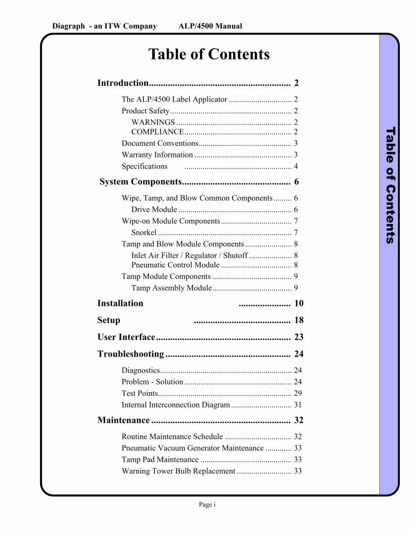
Diagraph - an ITW Company ALP/4500 ManualTable of C
ontents
Table of ContentsIntroduction............................................................ 2
The ALP/4500 Label Applicator ............................... 2Product Safety............................................................ 2
WARNINGS ......................................................... 2COMPLIANCE..................................................... 2
Document Conventions.............................................. 3Warranty Information ................................................ 3Specifications ..................................................... 4
System Components.............................................. 6
Wipe, Tamp, and Blow Common Components ......... 6Drive Module ........................................................ 6
Wipe-on Module Components................................... 7Snorkel .................................................................. 7
Tamp and Blow Module Components ....................... 8Inlet Air Filter / Regulator / Shutoff ..................... 8Pneumatic Control Module ................................... 8
Tamp Module Components ....................................... 9Tamp Assembly Module....................................... 9
Installation ...................... 10
Setup ......................................... 18
User Interface......................................................... 23
Troubleshooting ..................................................... 24
Diagnostics................................................................. 24Problem - Solution ..................................................... 24Test Points.................................................................. 29Internal Interconnection Diagram.............................. 31
Maintenance ........................................................... 32
Routine Maintenance Schedule ................................. 32Pneumatic Vacuum Generator Maintenance ............. 33Tamp Pad Maintenance ............................................. 33Warning Tower Bulb Replacement ........................... 33
Page i
Diagraph - an ITW Company ALP/4500 ManualTable of C
ontents
Fuse Replacement ...................................................... 34Power Inlet Module............................................... 34............................................................................... 34Power Supply Board Fuse Replacement ............... 34
Cooling Fan Filter Cleaning and Replacement.......... 35Pneumatic Filter Replacement ................................... 35
............................................................................... 35Pneumatic Control Module Muffler...................... 35
Unwind Slot Sensor Maintenance.............................. 35Band Brake / Unwind Spring Replacement ............... 36Rewind Belt Replacement ......................................... 36Drive Roller Replacement ......................................... 37Peel Blade Replacement ............................................ 37
Replacement Parts ................................................. 38
ALP/4500 Replacement Part List .............................. 38
Connection Port Information ............................... 40
Product Detector / Encoder Pin-Out .......................... 40 Auxiliary Output Pin-Out ......................................... 40 Warning Tower Pin-Out ........................................... 41 Serial Communication Pin-Out................................. 41
Declaration of Conformity .................................... 42
Page ii
Diagraph - an ITW Company ALP/4500 LA Manual
Diagraph, an ITW company, continually improves its products, and reserves the right to change or discon-tinue specifications and designs shown in this manual without notice and without incurring obligation. Diagraph has made every effort to verify the informa-tion contained in this manual, but reserves the right to correct any error at the time of the manual’s next revision.© 2004 Illinois Tool Works Inc. All rights reserved.Printed in the United States of America
Page 1
Diagraph - an ITW Company ALP/4500 LA ManualIntroduction
1.0 Introduction
1.1 The ALP/4500 Label Applicator
The ALP/4500 LA is an advanced label applicator designed for modularity, continuous labeling, self-diagnostics, and ease of use. Modularity of design provides the basis for ease of installation, setup, and maintenance. A central, consolidated operator interface is comprised of a graphics display and keypad, which controls the applicator settings. Through the use of the symbol and text-based menu screens, the operator is able to view several parameters at once, in a meaning-ful manner. Advanced electronics automatically self-calibrates sensors. Next-generation diag-nostics automatically monitors input sensors and output drivers and protects against shorts and overloads. This labeling system is capable of high volume industrial applications, providing the highest efficiency through a combination of intelligent electronic sensing and an efficient web path design.
1.2 Product Safety
Safety awareness is critical when working with equipment that contains moving parts and extending pneumatic cylinders. Please read all warnings and cautions thoroughly before operating this device.
This product meets the requirements of CAN/CSA-22.2 NO.60950-00 * UL 60950 using Diagraph an ITW Company approved items. Units are only tested and qualified with Diagraph an ITW Company approved parts and accessories. Use of other parts or accessories may introduce potential risks that Diagraph an ITW Company can assume no liability for.
WARNINGS
• WARNING - Moving parts of this machine can present hazards. Components that cannot be guarded because of loss of functionality are marked with a warning symbol.
• Be aware of the tamp cylinder extension distance, and avoid accidental trig-gering of the photosensor.
• When servicing the unit’s electronic assemblies, always remove the power cord from the unit to prevent accidental shock.
• When running for extended periods of time, use caution when accessing the drive module circuitry. The motor drive power transistors, motor case, and motor heatsink can become hot under constant use.
• Always close the air inlet valve shutoff when removing or servicing pneu-matic module or tamp cylinder.
• Wear personal protective equipment, as instructed by your supervisor, when operating or working near this device.
Introduction Page 2
Diagraph - an ITW Company ALP/4500 LA ManualIntroduction
COMPLIANCE
• CAUTION: Not for use in a computer room as defined in the Standard for the Protection of Electronic Computer/ Data Processing Equipment, ANSI/NFPA 75.
• ATTENTION: Ne peut être utilissé dans une salle d’ordinateurs telle que définie dans las norme. ANSI/NFPA 75 Standard for the Protection of Elec-tronic Computer/ Data Processing Equipment
• This unit has been tested and found to comply with the limits for a Class A device, pursuant to part 15 of the FCC Rules.
• This unit has been tested to comply with CE Standards.
• This unit is equipped with an Emergency Stop switch. Depressing this switchwill cause all machine operations to cease.
• This unit was tested and it was determined that a potential for tipping exists in certain orientations. In compliance with UL safety standards, the stand must be secured to the surface where it is located. Additionally, this type of securing will result in greater product application accuracy.
1.3 Document Conventions
Formatting conventions are used throughout this manual as a method of providing consistency for notes and warnings.
.
.
1.4 Warranty Information
The ALP/4500 LA system, including all components unless otherwise specified, carries a limited warranty.
For all warranty terms and conditions, contact Diagraph, an ITW Company, for a complete copy of the Limited Warranty Statement.
NoteThis symbol appears throughout the manual to provide additional information on a topic, including technical details, exceptions to the instructions and other pertinent information. Notes are identified with a note pad and pen symbol and italics text.
WARNING This symbol indicates a danger of injury to the user. Hazards are identified by the exclamation mark in a triangle and bold italics text.
Introduction Page 3
Diagraph - an ITW Company ALP/4500 LA ManualIntroduction
1.5 Specifications
General Specifications
Category Parameter
Dimensions 28 in. L x 21 in. H x 23 in. D (includes Yoke)
Weight 86 lbs (39 kg)
Accuracy ±0.06 in. (±1.6 mm)
Certifications Œ, CSA, FCC approved, ETL Listed (UL 60950)
Supply Roll Capacity 12 in. (304.8 mm)16 in. (406.4 mm) Optional
Dispense Speed 15 to 300 Feet Per Minute (76 to 1500 cm/s)
Label Length 0.5 in. (12.7 mm) Min. to 22.0 in. (558.8 mm) Max.
Label Width 0.5 in. (12.7 mm) Min. to 5.0 in. (127 mm) Max.
Product Rate 900 PPM Max.
Temperature 41°F - 104°F
Humidity 10 to 85% RH, Non-Condensing
Electrical Specifications
Category Nominal Minimum Maximum
AC VoltageSupply
110-120 VAC, 5A 50/60 Hz220-240 VAC, 3A50/60 Hz
85 VAC
190 VAC
132 VAC
254 VAC
Product Detector(Sensor Mode)
Low: 0 to 3 VDCHigh: 3 to 5 VDCSupplies 24VDC
0 VDC 6.8 VDC
Product Detector(PLC Mode)
Low: 0 to 3 VDCHigh: 3 to 5 VDC
0 VDC 6.8 VDC
Product Detector Pulse Width(Either Mode)
10 mS 1 mS Infinite
Auxiliary OutputWarning Tower
0 and 24 VDC2 A sinking
0 VDC0 mA
24 VDC4 A sinking
Discrete Inputs(Optional)
Low: 0 to 10 VDCHigh: 10 to 24 VDC
0 VDC 26 VDC
Discrete Outputs(Optional)
0 - 240 V AC/DC at 150 mA
0 V AC/DC, 13 ohms
250 V AC/DC at 170 mA
Introduction Page 4
Diagraph - an ITW Company ALP/4500 LA ManualIntroduction
Mechanical Specifications - Tamp System
Category Nominal Minimum Maximum
Incoming Air Pressure 60 - 100 PSI 40 PSI 125 PSI
Tamp Cylinder Pressure 30 - 50 PSI 20 PSI 80 PSI
Air Assist Pressure 5 - 30 PSI 0 PSI 50 PSI
Vacuum GeneratorPressure
20 - 55 PSI 15 PSI 60 PSI
Tamp Stroke(10 in. cylinder)
1 - 9 in.25.4-228 mm.
0.5 in.12.7 mm.
9.5 in.241.3 mm.
Tamp Stroke(20 in. cylinder)
1 - 19 in.25.4-482 mm.
0.5 in.12.7 mm.
19.5 in.495.3 mm.
Air Consumption 5 CFM at 80 PSI
3 CFM at 80 PSI
7 CFM at 80 PSI
Mechanical Specifications - Blow System
Category Nominal Minimum Maximum
Incoming Air Pressure 60 - 80 PSI 40 PSI 125 PSI
Blow Pressure 60 PSI 20 PSI 100 PSI
Air Assist Pressure 5 - 30 PSI 0 PSI 50 PSI
Blow Distance 1 - 2 in.25.4-51 mm.
0.5 in.12.7 mm.
4 in.101.6 mm.
Air Consumption Dependant on Application
1 CFM at 80 PSI
10 CFM at80 PSI
Introduction Page 5
Diagraph - an ITW Company ALP/4500 LA ManualS
ystem C
omponents
2.0 System Components
2.1 Wipe, Tamp, and Blow Common Components
Drive Module
(Left-Handed Snorkel Shown)
Description
Four corner screws retain the Drive Module. Behind the plate, there are three cable connections. These include the power, serial, and logic cables.
Installation/Removal
The Drive Module contains the label feed system components. This module is comprised of the centerwall plate, drive roller, nip lever and roller, BLDC motor, and circuitry.
Nip Lever
Nip Roller
Drive Roller
Part Numbers
P/N Description
6146-637 Nip Lever Assembly
6146-638 Nip Roller
6146-630 Drive Roller Assembly
6146-640 Knob, Black
Knob
Assembly
System Components Page 6
Diagraph - an ITW Company ALP/4500 LA ManualS
ystem C
omponents
2.2 Wipe-on Module Components
Snorkel
DescriptionTo remove the snorkel with the drive module, remove the four (4) corner screws on the centerwall plate. To remove just the snorkel unit, unscrew the two (2) socket head cap screws on the top cross-member, which connect to the extension arms. Be careful to keep stress off of the cabling once detached.
Installation/RemovalThe Snorkel Module contains the label transfer system components. This module is comprised of the snorkel arms, peel blade and support, brush hardware, hold down plate, gap sensor, and product detection sensor.
Extension Arm
Brush
Hold Down
Web Guide
Peel Blade Peel BladeSupport
InternalProductSensor
Part Numbers
P/N Description
6146-623 Extension Arm (Each)
6146-601 Snorkel Bracket
6146-602 Snorkel Cross-Member
6146-616 Peel Blade Support
6146-617 Peel Blade
6146-624 Brush (option 1) - 1.25 in.
6146-611 Brush (option 2) - 1.92 in.
6146-612 Hold Down Plate
P/N Description
6146-613 Web Guide (Outer or Inner)
6146-906 Internal Product Sensor
6146-615L Label Gap Sensor - Left Hand Unit
6146-615R Label Gap Sensor - Right Hand Unit
Bracket
Cross-Member
(Outer)
Label GapSensor
System Components Page 7
Diagraph - an ITW Company ALP/4500 LA ManualS
ystem C
omponents
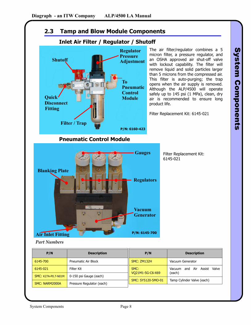
2.3 Tamp and Blow Module Components
Inlet Air Filter / Regulator / Shutoff
Pneumatic Control Module
The air filter/regulator combines a 5 micron filter, a pressure regulator, and an OSHA approved air shut-off valve with lockout capability. The filter will remove liquid and solid particles larger than 5 microns from the compressed air. This filter is auto-purging; the trap opens when the air supply is removed. Although the ALP/4500 will operate safely up to 145 psi (1 MPa), clean, dry air is recommended to ensure long product life.
Filter Replacement Kit: 6145-021
To PneumaticControlModuleQuick
Fitting
RegulatorPressure AdjustmentShutoff
Filter / Trap
Disconnect
P/N: 6160-423
Gauges
Regulators
Blanking Plate
Vacuum
Air Inlet Fitting
Generator
P/N: 6145-700
Filter Replacement Kit: 6145-021
Part Numbers
P/N Description
6145-700 Pneumatic Air Block
6145-021 Filter Kit
SMC: K27A-P0.7-N01M 0-150 psi Gauge (each)
SMC: NARM2000A Pressure Regulator (each)
P/N Description
SMC: ZM132H Vacuum Generator
SMC: VQ21M1-5G-C6-X69
Vacuum and Air Assist Valve (each)
SMC: SY5120-5MO-01 Tamp Cylinder Valve (each)
System Components Page 8
Diagraph - an ITW Company ALP/4500 LA ManualS
ystem C
omponents
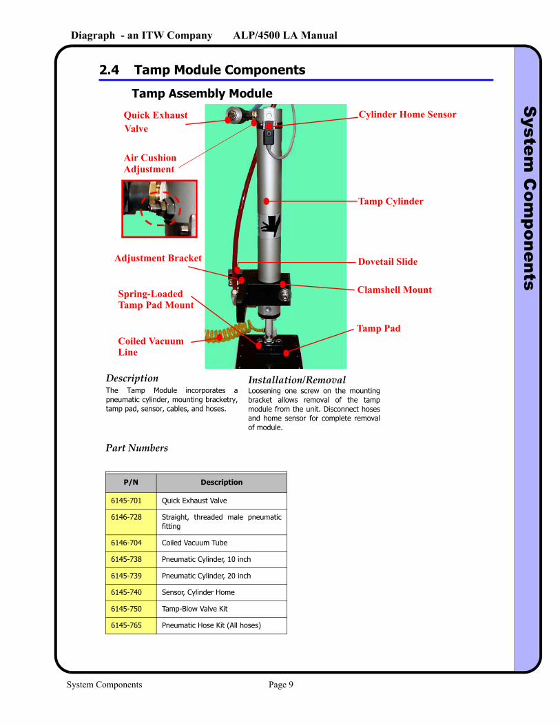
2.4 Tamp Module Components
Tamp Assembly Module
Quick ExhaustValve
Cylinder Home Sensor
Dovetail Slide
Clamshell MountSpring-Loaded
Tamp Pad
Air CushionAdjustment
Tamp Cylinder
Adjustment Bracket
Tamp Pad Mount
DescriptionLoosening one screw on the mounting bracket allows removal of the tamp module from the unit. Disconnect hoses and home sensor for complete removal of module.
Installation/RemovalThe Tamp Module incorporates a pneumatic cylinder, mounting bracketry, tamp pad, sensor, cables, and hoses.
Part Numbers
P/N Description
6145-701 Quick Exhaust Valve
6146-728 Straight, threaded male pneumatic fitting
6146-704 Coiled Vacuum Tube
6145-738 Pneumatic Cylinder, 10 inch
6145-739 Pneumatic Cylinder, 20 inch
6145-740 Sensor, Cylinder Home
6145-750 Tamp-Blow Valve Kit
6145-765 Pneumatic Hose Kit (All hoses)
Coiled VacuumLine
System Components Page 9
Diagraph - an ITW Company ALP/4500 LA ManualInstallation
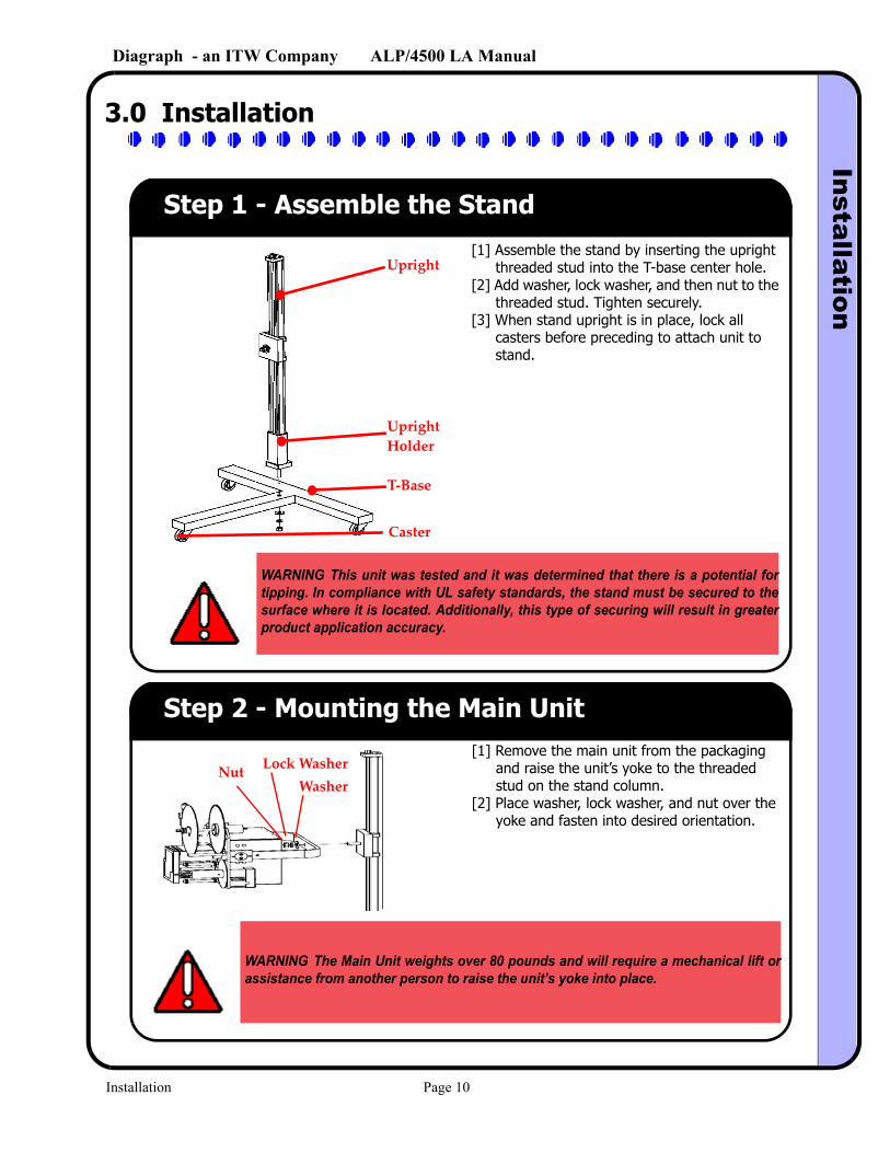
3.0 Installation
Step 1 - Assemble the Stand[1] Assemble the stand by inserting the upright
threaded stud into the T-base center hole. [2] Add washer, lock washer, and then nut to the
threaded stud. Tighten securely. [3] When stand upright is in place, lock all
casters before preceding to attach unit to stand.
Upright
UprightHolder
T-Base
Caster
WARNING This unit was tested and it was determined that there is a potential for tipping. In compliance with UL safety standards, the stand must be secured to the surface where it is located. Additionally, this type of securing will result in greater product application accuracy.
Step 2 - Mounting the Main Unit
Nut Lock WasherWasher
[1] Remove the main unit from the packaging and raise the unit’s yoke to the threaded stud on the stand column.
[2] Place washer, lock washer, and nut over the yoke and fasten into desired orientation.
WARNING The Main Unit weights over 80 pounds and will require a mechanical lift or assistance from another person to raise the unit’s yoke into place.
Installation Page 10
Diagraph - an ITW Company ALP/4500 LA ManualInstallation
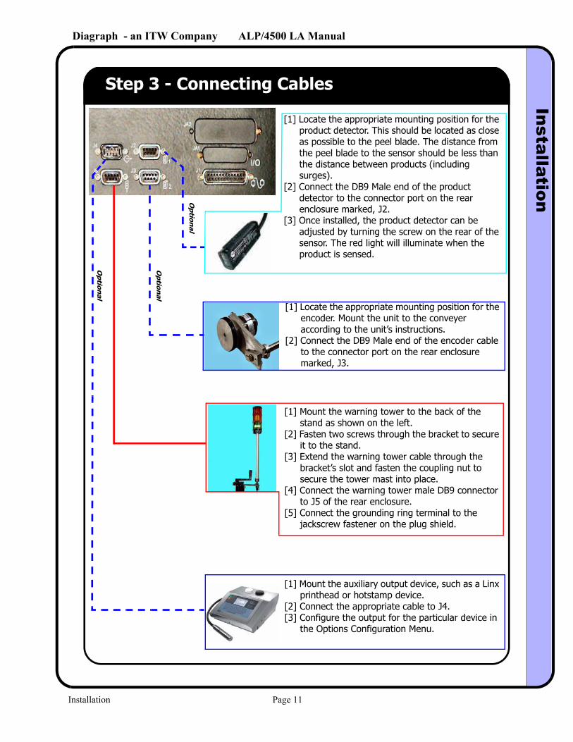
Step 3 - Connecting Cables
[1] Locate the appropriate mounting position for the product detector. This should be located as close as possible to the peel blade. The distance from the peel blade to the sensor should be less than the distance between products (including surges).
[2] Connect the DB9 Male end of the product detector to the connector port on the rear enclosure marked, J2.
[3] Once installed, the product detector can be adjusted by turning the screw on the rear of the sensor. The red light will illuminate when the product is sensed.
[1] Mount the warning tower to the back of the stand as shown on the left.
[2] Fasten two screws through the bracket to secure it to the stand.
[3] Extend the warning tower cable through the bracket’s slot and fasten the coupling nut to secure the tower mast into place.
[4] Connect the warning tower male DB9 connector to J5 of the rear enclosure.
[5] Connect the grounding ring terminal to the jackscrew fastener on the plug shield.
Op
tional
Op
tional
Op
tional
[1] Locate the appropriate mounting position for the encoder. Mount the unit to the conveyer according to the unit’s instructions.
[2] Connect the DB9 Male end of the encoder cable to the connector port on the rear enclosure marked, J3.
[1] Mount the auxiliary output device, such as a Linx printhead or hotstamp device.
[2] Connect the appropriate cable to J4.[3] Configure the output for the particular device in
the Options Configuration Menu.
Installation Page 11
Diagraph - an ITW Company ALP/4500 LA ManualInstallation
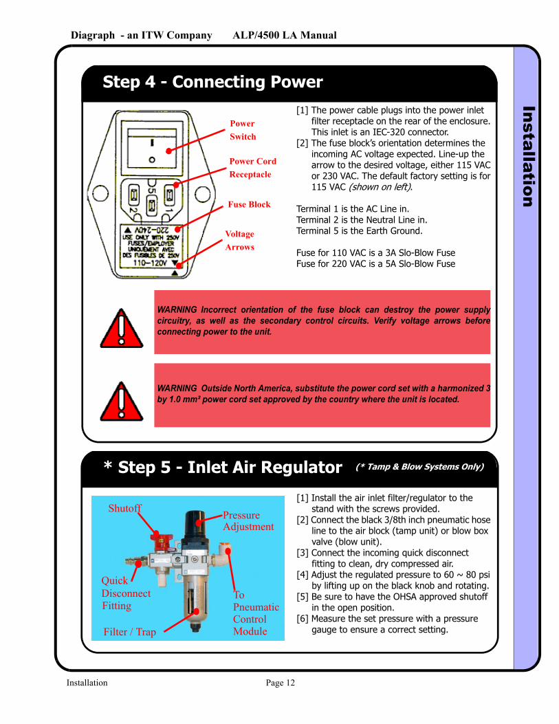
Step 4 - Connecting Power[1] The power cable plugs into the power inlet
filter receptacle on the rear of the enclosure. This inlet is an IEC-320 connector.
[2] The fuse block’s orientation determines the incoming AC voltage expected. Line-up the arrow to the desired voltage, either 115 VAC or 230 VAC. The default factory setting is for 115 VAC (shown on left).
Terminal 1 is the AC Line in.Terminal 2 is the Neutral Line in.Terminal 5 is the Earth Ground.
Fuse for 110 VAC is a 3A Slo-Blow FuseFuse for 220 VAC is a 5A Slo-Blow Fuse
Fuse Block
Voltage
Power CordReceptacle
PowerSwitch
Arrows
WARNING Incorrect orientation of the fuse block can destroy the power supply circuitry, as well as the secondary control circuits. Verify voltage arrows before connecting power to the unit.
WARNING Outside North America, substitute the power cord set with a harmonized 3 by 1.0 mm² power cord set approved by the country where the unit is located.
* Step 5 - Inlet Air Regulator (* Tamp & Blow Systems Only)
[1] Install the air inlet filter/regulator to the stand with the screws provided.
[2] Connect the black 3/8th inch pneumatic hose line to the air block (tamp unit) or blow box valve (blow unit).
[3] Connect the incoming quick disconnect fitting to clean, dry compressed air.
[4] Adjust the regulated pressure to 60 ~ 80 psi by lifting up on the black knob and rotating.
[5] Be sure to have the OHSA approved shutoff in the open position.
[6] Measure the set pressure with a pressure gauge to ensure a correct setting.
To PneumaticControlModule
Quick
Fitting
Pressure Adjustment
Shutoff
Filter / Trap
Disconnect
Installation Page 12
Diagraph - an ITW Company ALP/4500 LA ManualInstallation
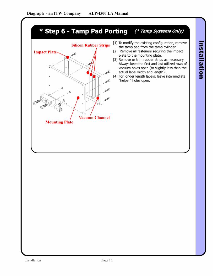
* Step 6 - Tamp Pad Porting (* Tamp Systems Only)
[1] To modify the existing configuration, remove the tamp pad from the tamp cylinder.
[2] Remove all fasteners securing the impact plate to the mounting plate.
[3] Remove or trim rubber strips as necessary. Always keep the first and last utilized rows of vacuum holes open (to slightly less than the actual label width and length).
[4] For longer length labels, leave intermediate “helper” holes open.
Silicon Rubber Strips
Vacuum Channel
Impact Plate
Mounting Plate
Installation Page 13
Diagraph - an ITW Company ALP/4500 LA ManualInstallation
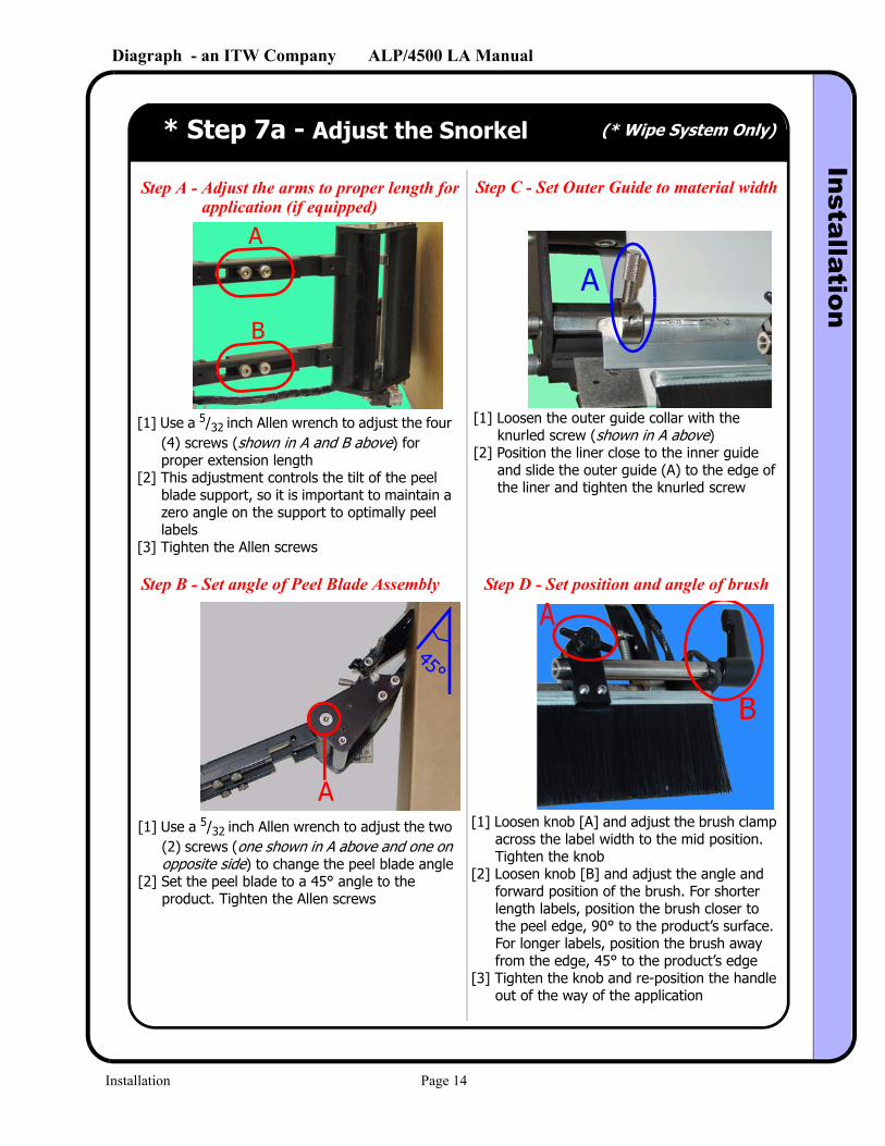
* Step 7a - Adjust the Snorkel (* Wipe System Only)
Step A - Adjust the arms to proper length for application (if equipped)
Step B - Set angle of Peel Blade Assembly
Step C - Set Outer Guide to material width
Step D - Set position and angle of brush
A
B
45°
A
A
B
A
[1] Use a 5/32 inch Allen wrench to adjust the four (4) screws (shown in A and B above) for proper extension length
[2] This adjustment controls the tilt of the peel blade support, so it is important to maintain a zero angle on the support to optimally peel labels
[3] Tighten the Allen screws
[1] Loosen the outer guide collar with the knurled screw (shown in A above)
[2] Position the liner close to the inner guide and slide the outer guide (A) to the edge of the liner and tighten the knurled screw
[1] Use a 5/32 inch Allen wrench to adjust the two (2) screws (one shown in A above and one on opposite side) to change the peel blade angle
[2] Set the peel blade to a 45° angle to the product. Tighten the Allen screws
[1] Loosen knob [A] and adjust the brush clamp across the label width to the mid position. Tighten the knob
[2] Loosen knob [B] and adjust the angle and forward position of the brush. For shorter length labels, position the brush closer to the peel edge, 90° to the product’s surface. For longer labels, position the brush away from the edge, 45° to the product’s edge
[3] Tighten the knob and re-position the handle out of the way of the application
Installation Page 14
Diagraph - an ITW Company ALP/4500 LA ManualInstallation
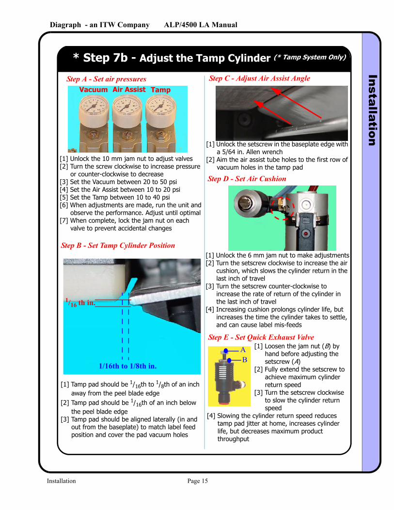
[1] Unlock the 10 mm jam nut to adjust valves[2] Turn the screw clockwise to increase pressure
or counter-clockwise to decrease[3] Set the Vacuum between 20 to 50 psi[4] Set the Air Assist between 10 to 20 psi[5] Set the Tamp between 10 to 40 psi[6] When adjustments are made, run the unit and
observe the performance. Adjust until optimal[7] When complete, lock the jam nut on each
valve to prevent accidental changes
* Step 7b - Adjust the Tamp Cylinder (* Tamp System Only)
Step A - Set air pressuresVacuum Air Assist Tamp
[1] Loosen the jam nut (B) by hand before adjusting the setscrew (A)
[2] Fully extend the setscrew to achieve maximum cylinder return speed
[3] Turn the setscrew clockwise to slow the cylinder return speed
[4] Slowing the cylinder return speed reduces tamp pad jitter at home, increases cylinder life, but decreases maximum product throughput
[1] Unlock the 6 mm jam nut to make adjustments[2] Turn the setscrew clockwise to increase the air
cushion, which slows the cylinder return in the last inch of travel
[3] Turn the setscrew counter-clockwise to increase the rate of return of the cylinder in the last inch of travel
[4] Increasing cushion prolongs cylinder life, but increases the time the cylinder takes to settle, and can cause label mis-feeds
[1] Tamp pad should be 1/16th to 1/8th of an inch away from the peel blade edge
[2] Tamp pad should be 1/16th of an inch below the peel blade edge
[3] Tamp pad should be aligned laterally (in and out from the baseplate) to match label feed position and cover the pad vacuum holes
AB
Step B - Set Tamp Cylinder Position
Step E - Set Quick Exhaust Valve
Step D - Set Air Cushion
Step C - Adjust Air Assist Angle
1/16 th in.
1/16th to 1/8th in.
[1] Unlock the setscrew in the baseplate edge with a 5/64 in. Allen wrench
[2] Aim the air assist tube holes to the first row of vacuum holes in the tamp pad
Installation Page 15

Diagraph - an ITW Company ALP/4500 LA ManualInstallation
* Step 7c - Adjust the Blow Module (* Blow System Only)
Installation Page 16
Diagraph - an ITW Company ALP/4500 LA ManualInstallation
Step 8 - Threading the Label Supply
Installation Page 17
Diagraph - an ITW Company ALP/4500 LA ManualS
etup
4.0 Setup
Step 1 - Application Configuration
Step A - Power up the unitStep B - Press the middle, right button when this screen appears (displayed for 2 seconds)
Step C - Enter the configuration for this systemFacing the nameplate of the labeler, this is the direction the labels will dispense.
This determines whether the unit advances past a missing label after the current label feed or upon the trigger of feeding the next label.
Exit this screen and return to the main menu.
Turning this “ON” allows the unit to power-up into the online, running mode without user interaction.
This selects if the numeric password is used to protect parameters.
This allows for changing the user password number.
.
Note The Missing Label Advance is most useful for round or odd-shaped label dispensing. To allow proper feeding for either of these two cases, select “BEFORE” and use the Feed Position adjustment to line up the label to the peel edge. A slide-across sensor is not required for these types of labels.
OFF RIGHT
AFTERON
####
Press
This enters the hidden configuration menu.
Setup Page 18
Diagraph - an ITW Company ALP/4500 LA ManualInstallation
Step 2 - Options ConfigurationStep A - From the Home Screen,
This selects the warning level diameter for the unwind supply.
This determines whether the unit uses a fixed dispense speed or an optional encoder signal on J3 allowing for variable speeds.
Exit this screen and return to the main menu.
Select which detector starts the process. Internal refers to the photosensor mounted on the snorkel, while PD1 Head is the leading edge of Product Detector 1.
Select mode of application.
This allows an optional trigger signal out of the auxiliary port J4.
press the Select button until Step B - Press the Options button the screen on the right appears
Step C - Enter the Options Configuration
...
Note The internal product detector is leading edge trigger only. A PLC can be connected as the start trigger through Product Detector 1.
NoteThe Auxiliary Output can directly trigger an IJ system, such as a Linx IJ Printer, where the trigger occurs when the label is at speed. The Hotstamp trigger occurs when movement has stopped. This output can sink up to 4 Amps and is fully protected.
NoteLabel Low is only a warning. Upon a low condition, the Warning Tower will light yellow, and a message will be displayed on the Home screen. Operation will continue until the Supply roll is exhausted.
INTERNAL 3.5 in.
WIPE
IJ TRIG
FIXED
Press Press
Setup Page 19
Diagraph - an ITW Company ALP/4500 LA ManualInstallation
Step 3 - Sensor CalibrationStep A - From the Home Screen,
Strip back several labels so that only liner is present under the gap sensor. Make sure that the liner is under light tension and press the Label Gap calibration button.
Feedback on the calibration process will appear here.
press the Select button until Step B - Press the Calibrate button the screen on the right appears
Step C - Calibrate the Label Gap Sensor
Use the actual product (box, container, etc.) as the calibration target. Place under the sensor and press the Product Detector calibrate button.
Feedback on the calibration process will appear here.
* Step D - (Optional) Calibrate the Internal Product Detector
Press
Press
If the calibration is not successful, check the troubleshooting section for details
If the calibration is not successful, check the troubleshooting section for details
Setup Page 20
Diagraph - an ITW Company ALP/4500 LA ManualInstallation
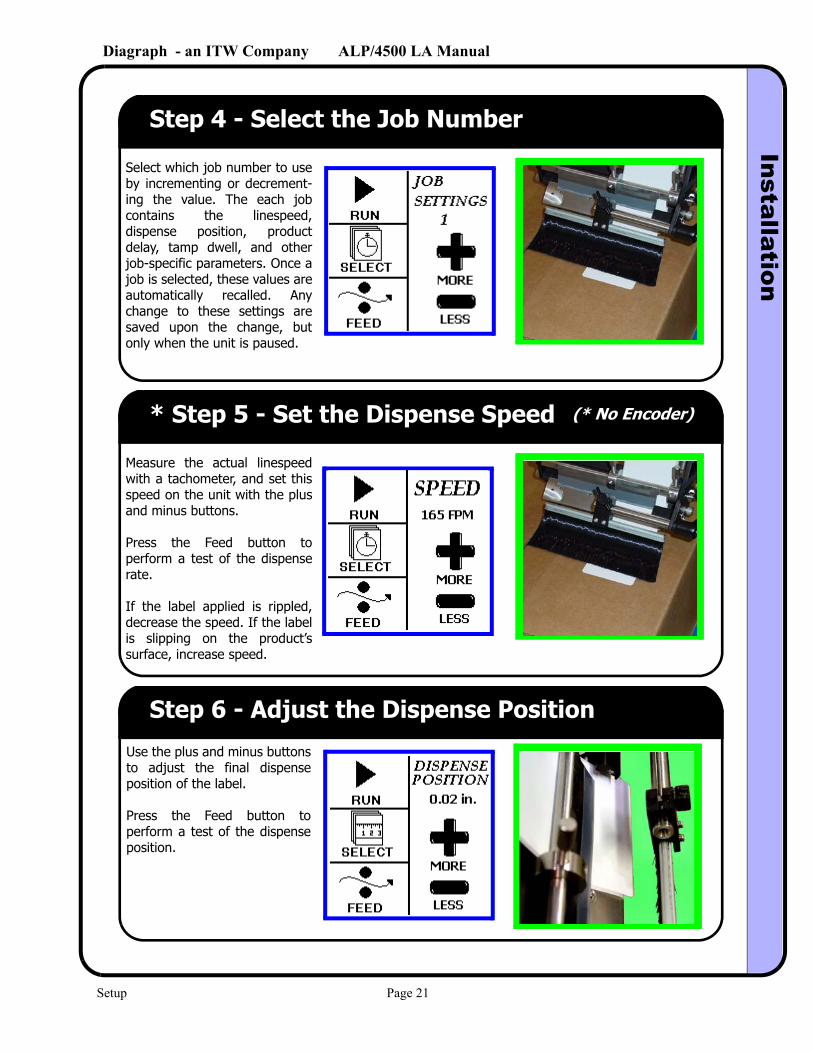
Step 4 - Select the Job Number
Select which job number to use by incrementing or decrement-ing the value. The each job contains the linespeed, dispense position, product delay, tamp dwell, and other job-specific parameters. Once a job is selected, these values are automatically recalled. Any change to these settings are saved upon the change, but only when the unit is paused.
* Step 5 - Set the Dispense Speed (* No Encoder)
Measure the actual linespeed with a tachometer, and set this speed on the unit with the plus and minus buttons.
Press the Feed button to perform a test of the dispense rate.
If the label applied is rippled, decrease the speed. If the label is slipping on the product’s surface, increase speed.
Step 6 - Adjust the Dispense Position
Use the plus and minus buttons to adjust the final dispense position of the label.
Press the Feed button to perform a test of the dispense position.
Setup Page 21
Diagraph - an ITW Company ALP/4500 LA ManualInstallation
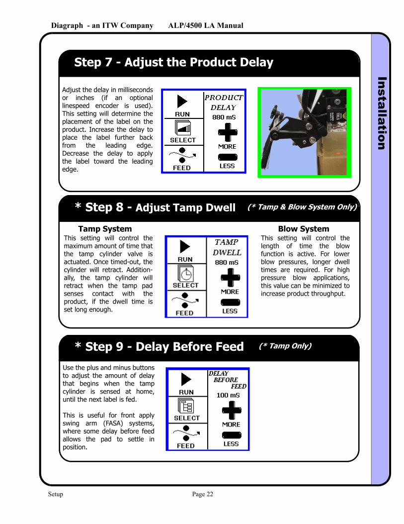
Step 7 - Adjust the Product Delay
Adjust the delay in milliseconds or inches (if an optional linespeed encoder is used). This setting will determine the placement of the label on the product. Increase the delay to place the label further back from the leading edge. Decrease the delay to apply the label toward the leading edge.
* Step 8 - Adjust Tamp Dwell (* Tamp & Blow System Only)
This setting will control the maximum amount of time that the tamp cylinder valve is actuated. Once timed-out, the cylinder will retract. Addition-ally, the tamp cylinder will retract when the tamp pad senses contact with the product, if the dwell time is set long enough.
Tamp System Blow SystemThis setting will control the length of time the blow function is active. For lower blow pressures, longer dwell times are required. For high pressure blow applications, this value can be minimized to increase product throughput.
* Step 9 - Delay Before Feed
Use the plus and minus buttons to adjust the amount of delay that begins when the tamp cylinder is sensed at home, until the next label is fed.
This is useful for front apply swing arm (FASA) systems, where some delay before feed allows the pad to settle in position.
(* Tamp Only)
Setup Page 22
Diagraph - an ITW Company ALP/4500 LA ManualU
ser Interface
5.0 User Interface
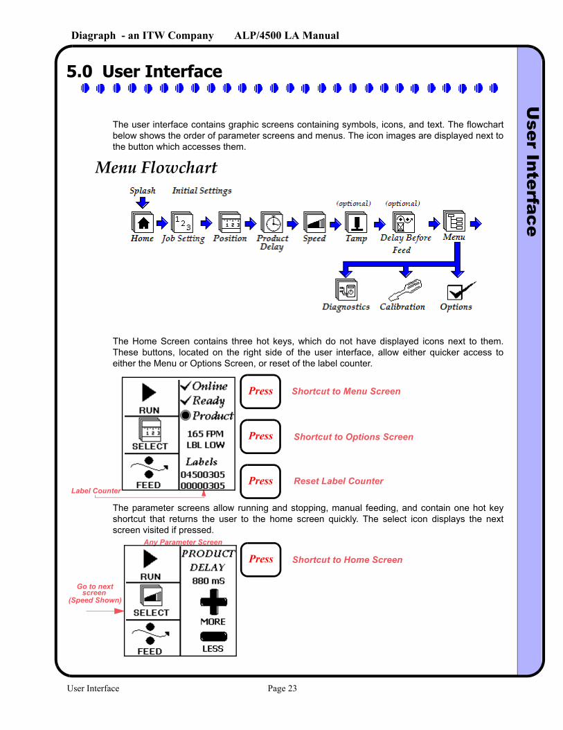
The user interface contains graphic screens containing symbols, icons, and text. The flowchart below shows the order of parameter screens and menus. The icon images are displayed next to the button which accesses them.
The Home Screen contains three hot keys, which do not have displayed icons next to them. These buttons, located on the right side of the user interface, allow either quicker access to either the Menu or Options Screen, or reset of the label counter.
The parameter screens allow running and stopping, manual feeding, and contain one hot key shortcut that returns the user to the home screen quickly. The select icon displays the next screen visited if pressed.
Menu Flowchart
Press
Press
Press
Shortcut to Menu Screen
Shortcut to Options Screen
Reset Label CounterLabel Counter
Press Shortcut to Home Screen
Go to nextscreen
(Speed Shown)
Any Parameter Screen
User Interface Page 23
Diagraph - an ITW Company ALP/4500 LA ManualTroubleshooting
6.0 Troubleshooting
6.1 Diagnostics
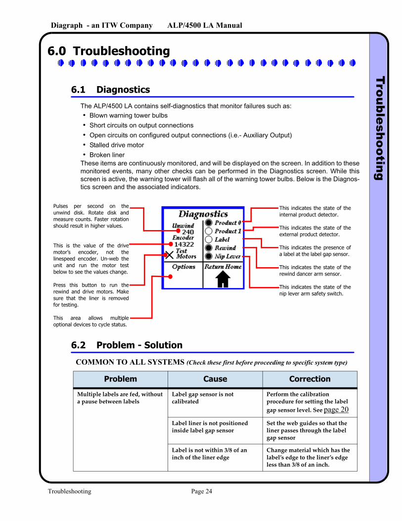
The ALP/4500 LA contains self-diagnostics that monitor failures such as:• Blown warning tower bulbs• Short circuits on output connections• Open circuits on configured output connections (i.e.- Auxiliary Output)• Stalled drive motor• Broken liner
These items are continuously monitored, and will be displayed on the screen. In addition to these monitored events, many other checks can be performed in the Diagnostics screen. While this screen is active, the warning tower will flash all of the warning tower bulbs. Below is the Diagnos-tics screen and the associated indicators.
6.2 Problem - Solution
COMMON TO ALL SYSTEMS (Check these first before proceeding to specific system type)
Problem Cause Correction
Multiple labels are fed, without a pause between labels
Label gap sensor is not calibrated
Perform the calibration procedure for setting the label gap sensor level. See page 20
Label liner is not positioned inside label gap sensor
Set the web guides so that the liner passes through the label gap sensor
Label is not within 3/8 of an inch of the liner edge
Change material which has the label’s edge to the liner’s edge less than 3/8 of an inch.
Pulses per second on the unwind disk. Rotate disk and measure counts. Faster rotation should result in higher values.
This is the value of the drive motor’s encoder, not the linespeed encoder. Un-web the unit and run the motor test below to see the values change.
Press this button to run the rewind and drive motors. Make sure that the liner is removed for testing.
This area allows multiple optional devices to cycle status.
This indicates the state of the internal product detector.
This indicates the state of the external product detector.
This indicates the presence of a label at the label gap sensor.
This indicates the state of the rewind dancer arm sensor.
This indicates the state of the nip lever arm safety switch.
Troubleshooting Page 24
Diagraph - an ITW Company ALP/4500 LA ManualTroubleshooting
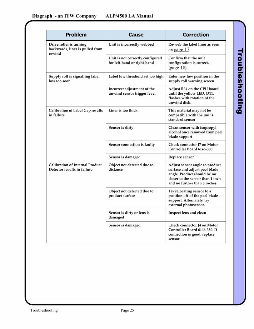
Drive roller is turning backwards, liner is pulled from rewind
Unit is incorrectly webbed Re-web the label liner as seen on page 17
Unit is not correctly configured for left-hand or right-hand
Confirm that the unit configuration is correct. (page 18)
Supply roll is signalling label low too soon
Label low threshold set too high Enter new low position in the supply roll warning screen
Incorrect adjustment of the unwind sensor trigger level
Adjust R34 on the CPU board until the yellow LED, D11, flashes with rotation of the unwind disk.
Calibration of Label Gap results in failure
Liner is too thick This material may not be compatible with the unit’s standard sensor
Sensor is dirty Clean sensor with isopropyl alcohol once removed from peel blade support
Sensor connection is faulty Check connector J7 on Motor Controller Board 6146-350
Sensor is damaged Replace sensor
Calibration of Internal Product Detector results in failure
Object not detected due to distance
Adjust sensor angle to product surface and adjust peel blade angle. Product should be no closer to the sensor than 1 inch and no further than 3 inches
Object not detected due to product surface
Try relocating sensor to a position off of the peel blade support. Alternately, try external photosensor.
Sensor is dirty or lens is damaged
Inspect lens and clean
Sensor is damaged Check connector J4 on Motor Controller Board 6146-350. If connection is good, replace sensor.
Problem Cause Correction
Troubleshooting Page 25
Diagraph - an ITW Company ALP/4500 LA ManualTroubleshooting
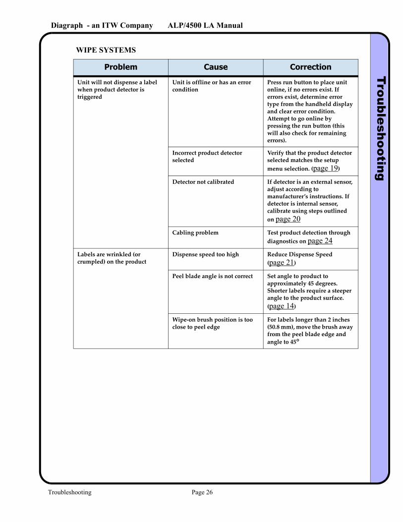
WIPE SYSTEMS
Problem Cause Correction
Unit will not dispense a label when product detector is triggered
Unit is offline or has an error condition
Press run button to place unit online, if no errors exist. If errors exist, determine error type from the handheld display and clear error condition. Attempt to go online by pressing the run button (this will also check for remaining errors).
Incorrect product detector selected
Verify that the product detector selected matches the setup menu selection. (page 19)
Detector not calibrated If detector is an external sensor, adjust according to manufacturer’s instructions. If detector is internal sensor, calibrate using steps outlined on page 20
Cabling problem Test product detection through diagnostics on page 24
Labels are wrinkled (or crumpled) on the product
Dispense speed too high Reduce Dispense Speed (page 21)
Peel blade angle is not correct Set angle to product to approximately 45 degrees. Shorter labels require a steeper angle to the product surface. (page 14)
Wipe-on brush position is too close to peel edge
For labels longer than 2 inches (50.8 mm), move the brush away from the peel blade edge and angle to 45°
Troubleshooting Page 26
Diagraph - an ITW Company ALP/4500 LA ManualTroubleshooting
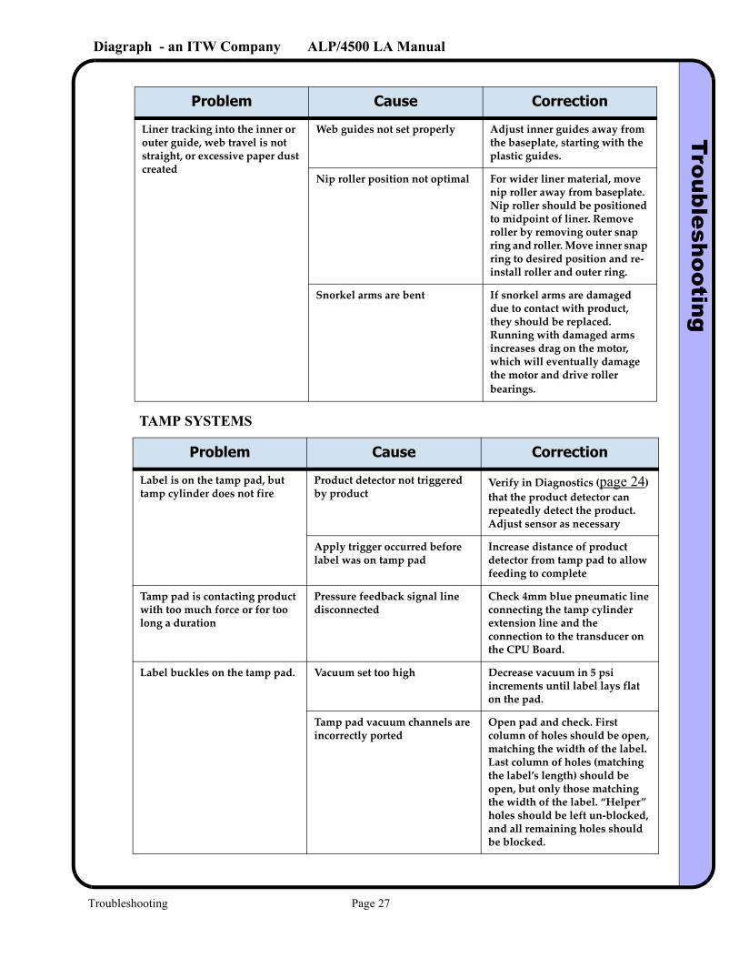
TAMP SYSTEMS
Liner tracking into the inner or outer guide, web travel is not straight, or excessive paper dust created
Web guides not set properly Adjust inner guides away from the baseplate, starting with the plastic guides.
Nip roller position not optimal For wider liner material, move nip roller away from baseplate. Nip roller should be positioned to midpoint of liner. Remove roller by removing outer snap ring and roller. Move inner snap ring to desired position and re-install roller and outer ring.
Snorkel arms are bent If snorkel arms are damaged due to contact with product, they should be replaced. Running with damaged arms increases drag on the motor, which will eventually damage the motor and drive roller bearings.
Problem Cause Correction
Label is on the tamp pad, but tamp cylinder does not fire
Product detector not triggered by product
Verify in Diagnostics (page 24) that the product detector can repeatedly detect the product. Adjust sensor as necessary
Apply trigger occurred before label was on tamp pad
Increase distance of product detector from tamp pad to allow feeding to complete
Tamp pad is contacting product with too much force or for too long a duration
Pressure feedback signal line disconnected
Check 4mm blue pneumatic line connecting the tamp cylinder extension line and the connection to the transducer on the CPU Board.
Label buckles on the tamp pad. Vacuum set too high Decrease vacuum in 5 psi increments until label lays flat on the pad.
Tamp pad vacuum channels are incorrectly ported
Open pad and check. First column of holes should be open, matching the width of the label. Last column of holes (matching the label’s length) should be open, but only those matching the width of the label. “Helper” holes should be left un-blocked, and all remaining holes should be blocked.
Problem Cause Correction
Troubleshooting Page 27
Diagraph - an ITW Company ALP/4500 LA ManualTroubleshooting
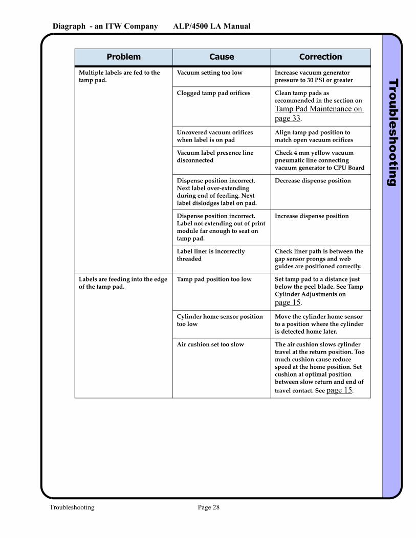
Multiple labels are fed to the tamp pad.
Vacuum setting too low Increase vacuum generator pressure to 30 PSI or greater
Clogged tamp pad orifices Clean tamp pads as recommended in the section on Tamp Pad Maintenance on page 33.
Uncovered vacuum orifices when label is on pad
Align tamp pad position to match open vacuum orifices
Vacuum label presence line disconnected
Check 4 mm yellow vacuum pneumatic line connecting vacuum generator to CPU Board
Dispense position incorrect. Next label over-extending during end of feeding. Next label dislodges label on pad.
Decrease dispense position
Dispense position incorrect. Label not extending out of print module far enough to seat on tamp pad.
Increase dispense position
Label liner is incorrectly threaded
Check liner path is between the gap sensor prongs and web guides are positioned correctly.
Labels are feeding into the edge of the tamp pad.
Tamp pad position too low Set tamp pad to a distance just below the peel blade. See Tamp Cylinder Adjustments on page 15.
Cylinder home sensor position too low
Move the cylinder home sensor to a position where the cylinder is detected home later.
Air cushion set too slow The air cushion slows cylinder travel at the return position. Too much cushion cause reduce speed at the home position. Set cushion at optimal position between slow return and end of travel contact. See page 15.
Problem Cause Correction
Troubleshooting Page 28
Diagraph - an ITW Company ALP/4500 LA ManualTroubleshooting
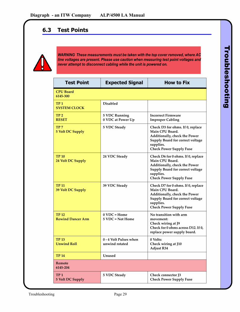
6.3 Test Points
WARNING These measurements must be taken with the top cover removed, where AC line voltages are present. Please use caution when measuring test point voltages and never attempt to disconnect cabling while the unit is powered on.
Test Point Expected Signal How to Fix
CPU Board 6145-300
TP 1SYSTEM CLOCK
Disabled
TP 2RESET
5 VDC Running0 VDC at Power Up
Incorrect FirmwareImproper Cabling
TP 75 Volt DC Supply
5 VDC Steady Check D3 for ohms. If 0, replace Main CPU Board.Additionally, check the Power Supply Board for correct voltage supplies.Check Power Supply Fuse
TP 1024 Volt DC Supply
24 VDC Steady Check D6 for 0 ohms. If 0, replace Main CPU Board.Additionally, check the Power Supply Board for correct voltage supplies.Check Power Supply Fuse
TP 1139 Volt DC Supply
39 VDC Steady Check D7 for 0 ohms. If 0, replace Main CPU Board.Additionally, check the Power Supply Board for correct voltage supplies.Check Power Supply Fuse
TP 12 Rewind Dancer Arm
0 VDC = Home5 VDC = Not Home
No transition with arm movement:Check wiring at J9Check for 0 ohms across D12. If 0, replace power supply board.
TP 13Unwind Roll
0 - 4 Volt Pulses when unwind rotated
0 Volts:Check wiring at J10Adjust R34
TP 14 Unused
Remote 6145-204
TP 15 Volt DC Supply
5 VDC Steady Check connector J3Check Power Supply Fuse
Troubleshooting Page 29
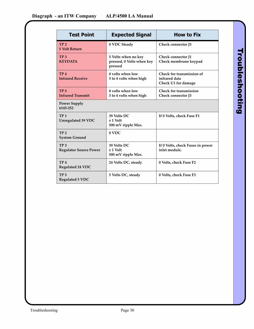
Diagraph - an ITW Company ALP/4500 LA ManualTroubleshooting
TP 25 Volt Return
0 VDC Steady Check connector J3
TP 3KEYDATA
5 Volts when no key pressed, 0 Volts when key pressed
Check connector J1Check membrane keypad
TP 4Infrared Receive
0 volts when low3 to 4 volts when high
Check for transmission of infrared dataCheck U1 for damage
TP 5Infrared Transmit
0 volts when low3 to 4 volts when high
Check for transmissionCheck connector J3
Power Supply6145-252
TP 1Unregulated 39 VDC
39 Volts DC± 1 Volt500 mV ripple Max.
If 0 Volts, check Fuse F1
TP 2System Ground
0 VDC
TP 3Regulator Source Power
39 Volts DC± 1 Volt500 mV ripple Max.
If 0 Volts, check Fuses in power inlet module.
TP 4Regulated 24 VDC
24 Volts DC, steady 0 Volts, check Fuse F2
TP 5Regulated 5 VDC
5 Volts DC, steady 0 Volts, check Fuse F3
Test Point Expected Signal How to Fix
Troubleshooting Page 30
Diagraph - an ITW Company ALP/4500 LA ManualTroubleshooting
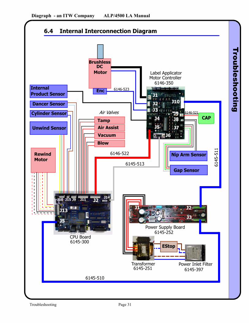
6.4 Internal Interconnection Diagram
Power Supply Board6145-252
Label Applicator
6146-350
CPU Board6145-300
6145
-511
6145-510
6145-513
6146-522
Blow
Vacuum
Air AssistTamp
Air Valves
Dancer Sensor
Cylinder Sensor
Unwind Sensor
CAP
Nip Arm Sensor
Gap Sensor
J10
J9J8
J7
J6
J5
J4
J1
J2J3
J3
J2J1J2J10 J15 J9 J11 J14
J13
J5
RewindMotor
InternalProduct Sensor
BrushlessDC
Motor
Enc
Power Inlet Filter6145-397
Transformer6145-251
6146-521
EStop
6146-523
Motor Controller
Troubleshooting Page 31
Diagraph - an ITW Company ALP/4500 LA ManualM
aintenance
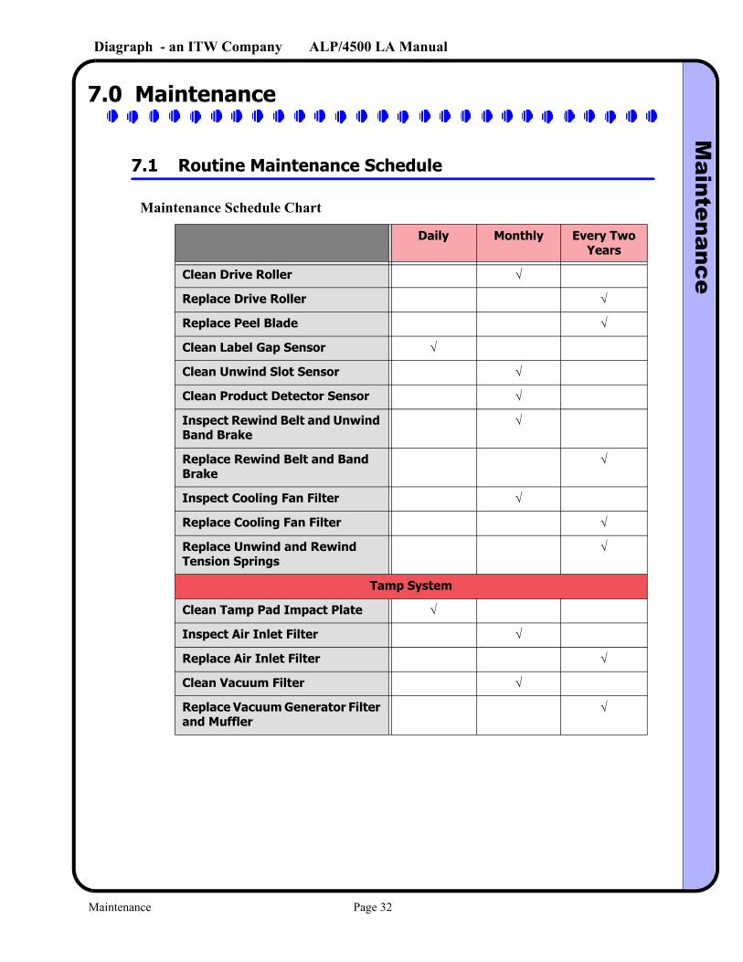
7.0 Maintenance
7.1 Routine Maintenance Schedule
Maintenance Schedule Chart
Daily Monthly Every Two Years
Clean Drive Roller √
Replace Drive Roller √
Replace Peel Blade √
Clean Label Gap Sensor √
Clean Unwind Slot Sensor √
Clean Product Detector Sensor √
Inspect Rewind Belt and Unwind Band Brake
√
Replace Rewind Belt and Band Brake
√
Inspect Cooling Fan Filter √
Replace Cooling Fan Filter √
Replace Unwind and Rewind Tension Springs
√
Tamp System
Clean Tamp Pad Impact Plate √
Inspect Air Inlet Filter √
Replace Air Inlet Filter √
Clean Vacuum Filter √
Replace Vacuum Generator Filter and Muffler
√
Maintenance Page 32
Diagraph - an ITW Company ALP/4500 LA ManualM
aintenance
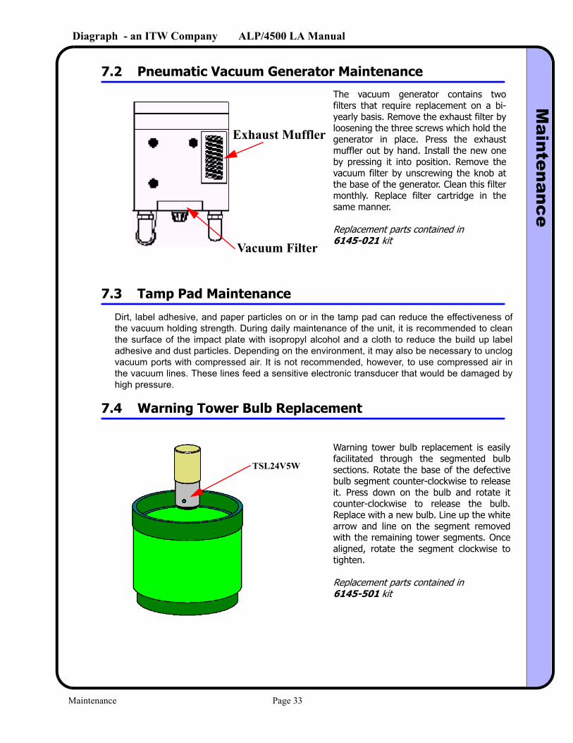
7.2 Pneumatic Vacuum Generator Maintenance
7.3 Tamp Pad Maintenance
Dirt, label adhesive, and paper particles on or in the tamp pad can reduce the effectiveness of the vacuum holding strength. During daily maintenance of the unit, it is recommended to clean the surface of the impact plate with isopropyl alcohol and a cloth to reduce the build up label adhesive and dust particles. Depending on the environment, it may also be necessary to unclog vacuum ports with compressed air. It is not recommended, however, to use compressed air in the vacuum lines. These lines feed a sensitive electronic transducer that would be damaged by high pressure.
7.4 Warning Tower Bulb Replacement
Exhaust Muffler
Vacuum Filter
The vacuum generator contains two filters that require replacement on a bi-yearly basis. Remove the exhaust filter by loosening the three screws which hold the generator in place. Press the exhaust muffler out by hand. Install the new one by pressing it into position. Remove the vacuum filter by unscrewing the knob at the base of the generator. Clean this filter monthly. Replace filter cartridge in the same manner.
Replacement parts contained in 6145-021 kit
TSL24V5W
Warning tower bulb replacement is easily facilitated through the segmented bulb sections. Rotate the base of the defective bulb segment counter-clockwise to release it. Press down on the bulb and rotate it counter-clockwise to release the bulb. Replace with a new bulb. Line up the white arrow and line on the segment removed with the remaining tower segments. Once aligned, rotate the segment clockwise to tighten.
Replacement parts contained in 6145-501 kit
Maintenance Page 33
Diagraph - an ITW Company ALP/4500 LA ManualM
aintenance
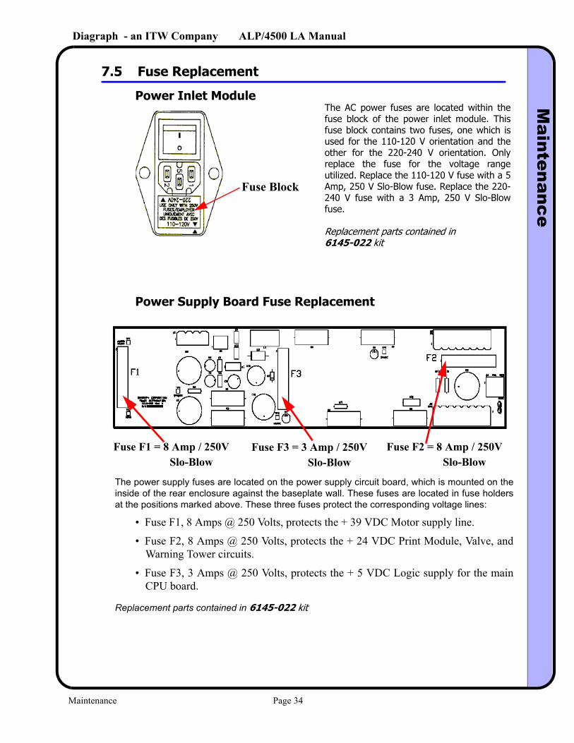
7.5 Fuse Replacement
Power Inlet Module
Power Supply Board Fuse Replacement
The power supply fuses are located on the power supply circuit board, which is mounted on the inside of the rear enclosure against the baseplate wall. These fuses are located in fuse holders at the positions marked above. These three fuses protect the corresponding voltage lines:
• Fuse F1, 8 Amps @ 250 Volts, protects the + 39 VDC Motor supply line.
• Fuse F2, 8 Amps @ 250 Volts, protects the + 24 VDC Print Module, Valve, and Warning Tower circuits.
• Fuse F3, 3 Amps @ 250 Volts, protects the + 5 VDC Logic supply for the main CPU board.
Replacement parts contained in 6145-022 kit
Fuse Block
The AC power fuses are located within the fuse block of the power inlet module. This fuse block contains two fuses, one which is used for the 110-120 V orientation and the other for the 220-240 V orientation. Only replace the fuse for the voltage range utilized. Replace the 110-120 V fuse with a 5 Amp, 250 V Slo-Blow fuse. Replace the 220-240 V fuse with a 3 Amp, 250 V Slo-Blow fuse.
Replacement parts contained in6145-022 kit
Fuse F1 = 8 Amp / 250VSlo-Blow
Fuse F3 = 3 Amp / 250VSlo-Blow
Fuse F2 = 8 Amp / 250VSlo-Blow
Maintenance Page 34
Diagraph - an ITW Company ALP/4500 LA ManualM
aintenance
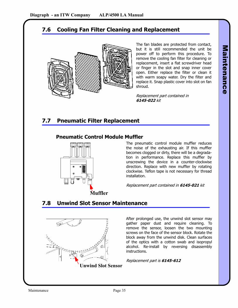
7.6 Cooling Fan Filter Cleaning and Replacement
7.7 Pneumatic Filter Replacement
Pneumatic Control Module Muffler
7.8 Unwind Slot Sensor Maintenance
The fan blades are protected from contact, but it is still recommended the unit be power off to perform this procedure. To remove the cooling fan filter for cleaning or replacement, insert a flat screwdriver head or finger in the slot and snap inner cover open. Either replace the filter or clean it with warm soapy water. Dry the filter and replace it. Snap plastic cover into slot on fan shroud.
Replacement part contained in6145-022 kit
Muffler
The pneumatic control module muffler reduces the noise of the exhausting air. If this muffler becomes clogged or dirty, there will be a degrada-tion in performance. Replace this muffler by unscrewing the device in a counter-clockwise direction. Replace with new muffler by rotating clockwise. Teflon tape is not necessary for thread installation.
Replacement part contained in 6145-021 kit
Unwind Slot Sensor
After prolonged use, the unwind slot sensor may gather paper dust and require cleaning. To remove the sensor, loosen the two mounting screws on the face of the sensor block. Rotate the block away from the unwind disk. Clean surfaces of the optics with a cotton swab and isopropyl alcohol. Re-install by reversing disassembly instructions.
Replacement part is 6145-612
Maintenance Page 35
Diagraph - an ITW Company ALP/4500 LA ManualM
aintenance
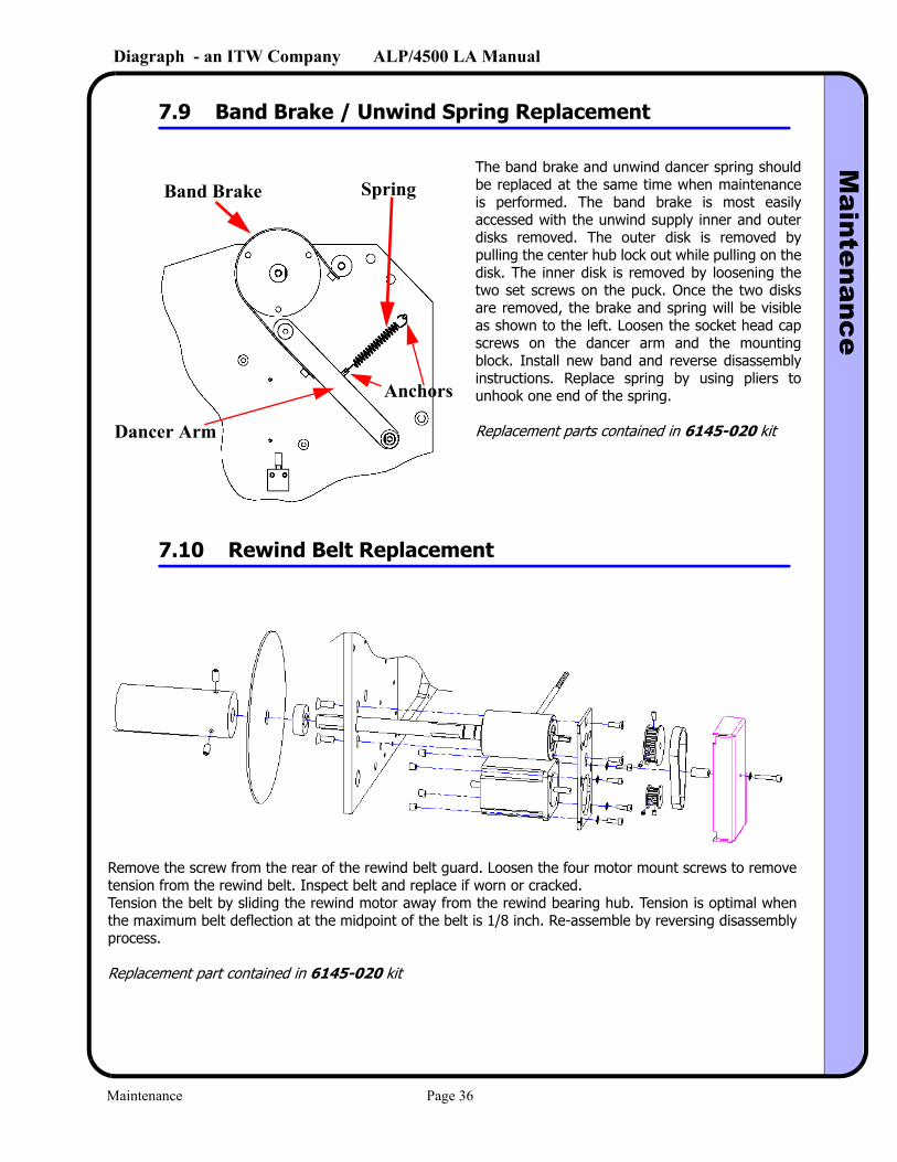
7.9 Band Brake / Unwind Spring Replacement
7.10 Rewind Belt Replacement
The band brake and unwind dancer spring should be replaced at the same time when maintenance is performed. The band brake is most easily accessed with the unwind supply inner and outer disks removed. The outer disk is removed by pulling the center hub lock out while pulling on the disk. The inner disk is removed by loosening the two set screws on the puck. Once the two disks are removed, the brake and spring will be visible as shown to the left. Loosen the socket head cap screws on the dancer arm and the mounting block. Install new band and reverse disassembly instructions. Replace spring by using pliers to unhook one end of the spring.
Replacement parts contained in 6145-020 kit
Band Brake Spring
Anchors
Dancer Arm
Remove the screw from the rear of the rewind belt guard. Loosen the four motor mount screws to remove tension from the rewind belt. Inspect belt and replace if worn or cracked. Tension the belt by sliding the rewind motor away from the rewind bearing hub. Tension is optimal when the maximum belt deflection at the midpoint of the belt is 1/8 inch. Re-assemble by reversing disassembly process.
Replacement part contained in 6145-020 kit
Maintenance Page 36
Diagraph - an ITW Company ALP/4500 LA ManualM
aintenance
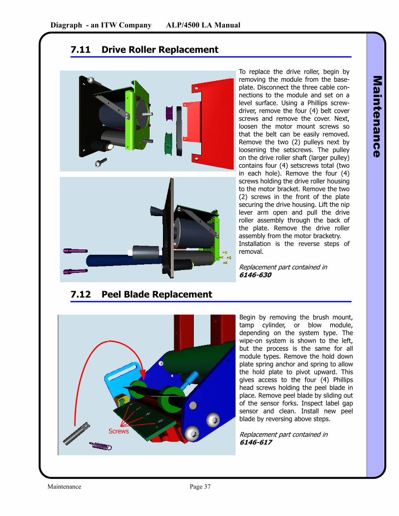
7.11 Drive Roller Replacement
7.12 Peel Blade Replacement
To replace the drive roller, begin by removing the module from the base-plate. Disconnect the three cable con-nections to the module and set on a level surface. Using a Phillips screw-driver, remove the four (4) belt cover screws and remove the cover. Next, loosen the motor mount screws so that the belt can be easily removed. Remove the two (2) pulleys next by loosening the setscrews. The pulley on the drive roller shaft (larger pulley) contains four (4) setscrews total (two in each hole). Remove the four (4) screws holding the drive roller housing to the motor bracket. Remove the two (2) screws in the front of the plate securing the drive housing. Lift the nip lever arm open and pull the drive roller assembly through the back of the plate. Remove the drive roller assembly from the motor bracketry. Installation is the reverse steps of removal.
Replacement part contained in6146-630
Screws
Begin by removing the brush mount, tamp cylinder, or blow module, depending on the system type. The wipe-on system is shown to the left, but the process is the same for all module types. Remove the hold down plate spring anchor and spring to allow the hold plate to pivot upward. This gives access to the four (4) Phillips head screws holding the peel blade in place. Remove peel blade by sliding out of the sensor forks. Inspect label gap sensor and clean. Install new peel blade by reversing above steps.
Replacement part contained in6146-617
Maintenance Page 37
Diagraph - an ITW Company ALP/4500 LA ManualM
aintenance
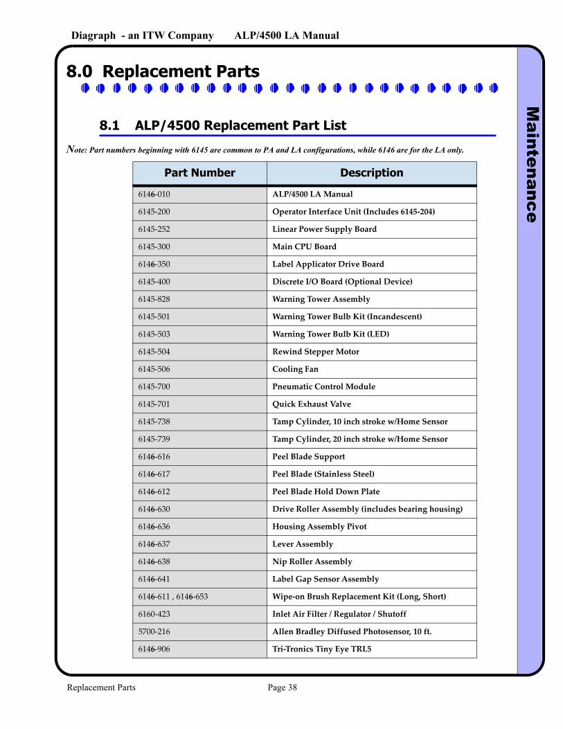
8.0 Replacement Parts
8.1 ALP/4500 Replacement Part List
Note: Part numbers beginning with 6145 are common to PA and LA configurations, while 6146 are for the LA only.
Part Number Description
6146-010 ALP/4500 LA Manual
6145-200 Operator Interface Unit (Includes 6145-204)
6145-252 Linear Power Supply Board
6145-300 Main CPU Board
6146-350 Label Applicator Drive Board
6145-400 Discrete I/O Board (Optional Device)
6145-828 Warning Tower Assembly
6145-501 Warning Tower Bulb Kit (Incandescent)
6145-503 Warning Tower Bulb Kit (LED)
6145-504 Rewind Stepper Motor
6145-506 Cooling Fan
6145-700 Pneumatic Control Module
6145-701 Quick Exhaust Valve
6145-738 Tamp Cylinder, 10 inch stroke w/Home Sensor
6145-739 Tamp Cylinder, 20 inch stroke w/Home Sensor
6146-616 Peel Blade Support
6146-617 Peel Blade (Stainless Steel)
6146-612 Peel Blade Hold Down Plate
6146-630 Drive Roller Assembly (includes bearing housing)
6146-636 Housing Assembly Pivot
6146-637 Lever Assembly
6146-638 Nip Roller Assembly
6146-641 Label Gap Sensor Assembly
6146-611 , 6146-653 Wipe-on Brush Replacement Kit (Long, Short)
6160-423 Inlet Air Filter / Regulator / Shutoff
5700-216 Allen Bradley Diffused Photosensor, 10 ft.
6146-906 Tri-Tronics Tiny Eye TRL5
Replacement Parts Page 38
Diagraph - an ITW Company ALP/4500 LA ManualM
aintenance
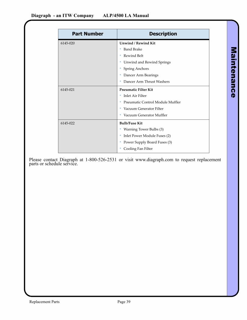
Please contact Diagraph at 1-800-526-2531 or visit www.diagraph.com to request replacement parts or schedule service.
6145-020 Unwind / Rewind Kit• Band Brake
• Rewind Belt
• Unwind and Rewind Springs
• Spring Anchors
• Dancer Arm Bearings
• Dancer Arm Thrust Washers
6145-021 Pneumatic Filter Kit• Inlet Air Filter
• Pneumatic Control Module Muffler
• Vacuum Generator Filter
• Vacuum Generator Muffler
6145-022 Bulb/Fuse Kit• Warning Tower Bulbs (3)
• Inlet Power Module Fuses (2)
• Power Supply Board Fuses (3)
• Cooling Fan Filter
Part Number Description
Replacement Parts Page 39
Diagraph - an ITW Company ALP/4500 LA ManualC
onnection Port Inform
ation
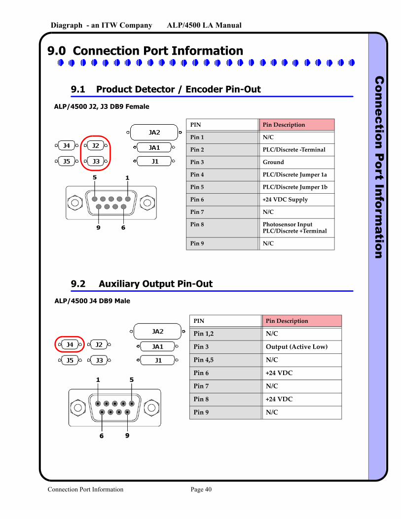
9.0 Connection Port Information
9.1 Product Detector / Encoder Pin-Out
9.2 Auxiliary Output Pin-Out
ALP/4500 J2, J3 DB9 Female
PIN Pin Description
Pin 1 N/C
Pin 2 PLC/Discrete -Terminal
Pin 3 Ground
Pin 4 PLC/Discrete Jumper 1a
Pin 5 PLC/Discrete Jumper 1b
Pin 6 +24 VDC Supply
Pin 7 N/C
Pin 8 Photosensor Input PLC/Discrete +Terminal
Pin 9 N/C
ALP/4500 J4 DB9 Male
PIN Pin Description
Pin 1,2 N/C
Pin 3 Output (Active Low)
Pin 4,5 N/C
Pin 6 +24 VDC
Pin 7 N/C
Pin 8 +24 VDC
Pin 9 N/C
Connection Port Information Page 40
Diagraph - an ITW Company ALP/4500 LA ManualC
onnection Port Inform
ation
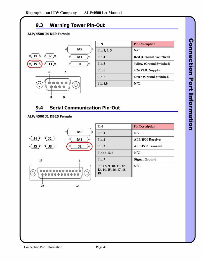
9.3 Warning Tower Pin-Out
9.4 Serial Communication Pin-Out
ALP/4500 J4 DB9 Female
PIN Pin Description
Pin 1, 2, 3 N/C
Pin 4 Red (Ground Switched)
Pin 5 Yellow (Ground Switched)
Pin 6 + 24 VDC Supply
Pin 7 Green (Ground Switched)
Pin 8,9 N/C
ALP/4500 J1 DB25 Female
PIN Pin Description
Pin 1 N/C
Pin 2 ALP/4500 Receive
Pin 3 ALP/4500 Transmit
Pins 4, 5, 6 N/C
Pin 7 Signal Ground
Pins 8, 9, 10, 11, 12, 13, 14, 15, 16, 17, 18, 19
N/C
Connection Port Information Page 41
Diagraph - an ITW Company ALP/4500 LA ManualD
eclaration of Conform
ity
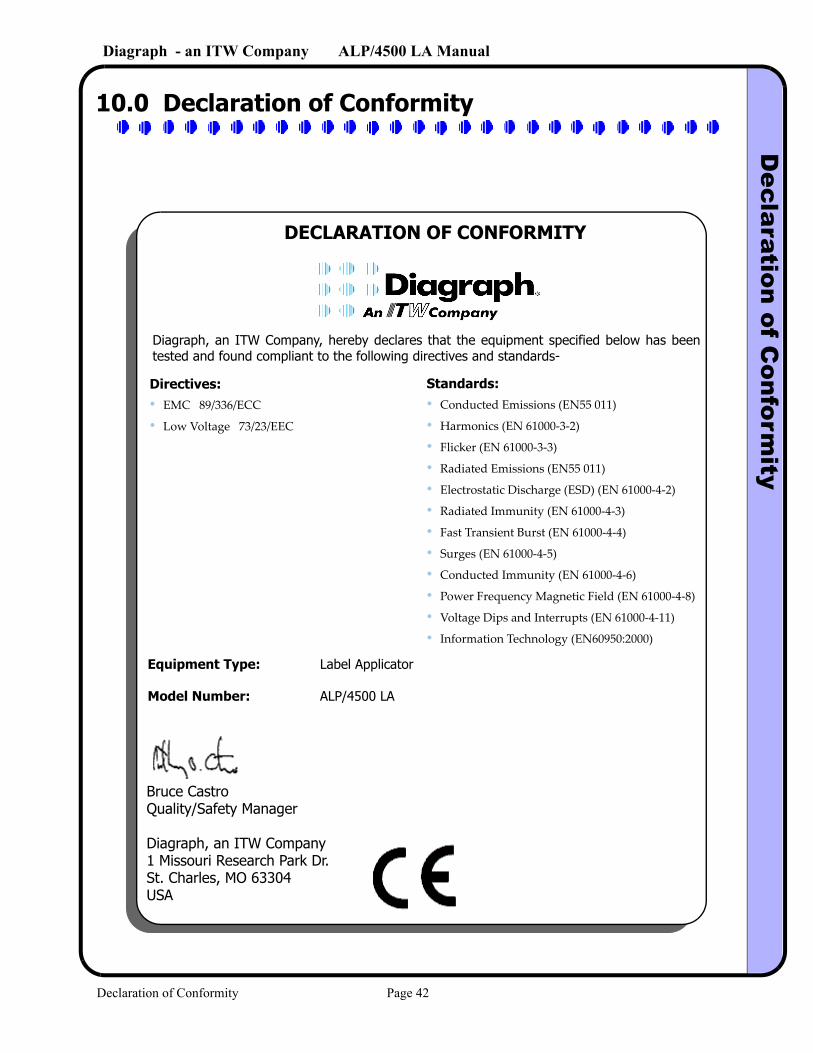
10.0 Declaration of Conformity
DECLARATION OF CONFORMITY
Diagraph, an ITW Company, hereby declares that the equipment specified below has been tested and found compliant to the following directives and standards-
Directives:• EMC 89/336/ECC
• Low Voltage 73/23/EEC
Standards:• Conducted Emissions (EN55 011)
• Harmonics (EN 61000-3-2)
• Flicker (EN 61000-3-3)
• Radiated Emissions (EN55 011)
• Electrostatic Discharge (ESD) (EN 61000-4-2)
• Radiated Immunity (EN 61000-4-3)
• Fast Transient Burst (EN 61000-4-4)
• Surges (EN 61000-4-5)
• Conducted Immunity (EN 61000-4-6)
• Power Frequency Magnetic Field (EN 61000-4-8)
• Voltage Dips and Interrupts (EN 61000-4-11)
• Information Technology (EN60950:2000)
Equipment Type: Label Applicator
Model Number: ALP/4500 LA
Bruce CastroQuality/Safety Manager
Diagraph, an ITW Company1 Missouri Research Park Dr.St. Charles, MO 63304USA
Declaration of Conformity Page 42


![Service/Technical Manual - SIGMA Equipment1].… · Service/Technical Manual Diagraph PA/4000 ... • An air cylinder tamp head assembly with auto-retract that apply labels with](https://img.pdfslide.us/doc/110x75/5b81c7ee7f8b9ae97b8d0477/servicetechnical-manual-sigma-equipment-1-servicetechnical-manual-diagraph.jpg)