Embed Size (px)
Citation preview

Aloyco
THE FIRST NAME IN CORROSION RESISTANT VALVES
Corrosion Resistant Valves

T: 562-426-2531 • F: 562-490-9546 • www.cranevalve.com 3
Figure No. Valve Type Pressure Class End Connection Material Available Size Range Catalog Page
90 Gate, RS 200 CWP Threaded CF8M 1⁄2" - 2" 5
190 Gate, NRS 200 CWP Threaded CF8M 1⁄2" - 2" 5
110 Gate, OS&Y 150 Threaded CF3M 1⁄2" - 2" 6
114 Gate, OS&Y 150 Socket Weld CF3M 1⁄2" - 2" 6
117, 117F Gate, OS&Y 150 Flanged CF8M 1⁄2" - 24" 7
2110 Gate, OS&Y 300 Threaded CF3M 1⁄2" - 2" 8
2114 Gate, OS&Y 300 Socket Weld CF3M 1⁄2" - 2" 8
2117, 2117F Gate, OS&Y 300 Flanged CF8M 1⁄2" - 24" 9
4210 Gate, OS&Y 600 Threaded CF3M 1⁄2" - 2" 10
4214 Gate, OS&Y 600 Socket Weld CF3M 1⁄2" - 2" 10
4217, 4117F Gate, OS&Y 600 Flanged CF8M 1⁄2" - 24" 11
40 Globe 200 CWP Threaded CF8M 1⁄2" - 2" 12
310 Globe 150 Threaded CF3M 1⁄2" - 2" 13
314 Globe 150 Socket Weld CF3M 1⁄2" - 2" 13
317 Globe 150 Flanged CF8M 1⁄2" - 12" 14
2310 Globe 300 Threaded CF3M 1⁄2" - 2" 15
2314 Globe 300 Socket Weld CF3M 1⁄2" - 2" 15
2317 Globe 300 Flanged CF8M 1⁄2" - 8" 16
4310 Globe 600 Threaded CF3M 1⁄2" - 2" 17
4314 Globe 600 Socket Weld CF3M 1⁄2" - 2" 17
4317 Globe 600 Flanged CF8M 1⁄2" - 6" 18
49 Swing Check 200 CWP Threaded CF8M 1⁄2" - 2" 19
370 Swing Check 150 Threaded CF3M 1⁄2" - 2" 20
374 Swing Check 150 Socket Weld CF3M 1⁄2" - 2" 20
377 Swing Check 150 Flanged CF8M 1⁄2" - 24" 21
2370 Swing Check 300 Threaded CF3M 1⁄2" - 2" 22
2374 Swing Check 300 Socket Weld CF3M 1⁄2" - 2" 22
2377 Swing Check 300 Flanged CF8M 1⁄2" - 24" 23
4370 Swing Check 600 Threaded CF3M 1⁄2" - 2" 24
4374 Swing Check 600 Socket Weld CF3M 1⁄2" - 2" 24
4377 Swing Check 600 Flanged CF8M 1⁄2" - 12" 25
9502 Ball - 2 pc 2000 CWP Threaded CF8M 1⁄4" - 2" 26
Stainless Steel ValvesGeneral Index
T: 256-775-3800 • F: 256-775-3860 • www.cranevalve.com

T: 256-775-3800 • F: 256-775-3860 • www.cranevalve.com4
Testing
Materials
How to Specify and Order the Correct ValvesThis catalog has been published to assist you in choosingthe correct valve for a vast number of piping conditions. TheAloyco product line makes available to you a very broadchoice of valves. These valves are described in this catalog.
Care should be taken to select the most suitable valves foryour service(s). Exact specification of each valve should bemade to avoid possible ambiguity. When requesting quota-tions and/or ordering the product a fully adequate descrip-tion should be made.
Selecting the Valve SizeNominal size of the pipeline into which the valve will beplaced must be determined.
Valve MaterialThe following facts should be considered in determining thecorrect valve material:
• the medium or media which will be controlled• the temperature range of the line medium (media)• the pressure range to which the valve will be subjected• possible atmospheric conditions which may affect
the valve• possible extraordinary stresses to which the valve will
be subjected• safety standards and/or piping codes which must be met
Type of ValveWhat is the control function of the valve? Each valve con-figuration has been developed to perform certain controlfunctions. Do not expect one type of valve to perform all thevalving jobs in a system.
Pressure-Temperature RatingsPlease pay careful attention that the pressure-temperatureratings of a particular valve are in keeping with the require-ments of the service. Pay especially careful attention to thepacking and gasket materials as this may limit the rating asis the case with PTFE used as the standard in Aloyco valves.Specify alternative packing and/or gasket materials as nec-essary to meet or exceed your service requirements.
How To OrderStainless Steel Valves
Valve and ConnectionsConsiderations as to pipeline integrity, future maintenance,corrosion factors, field assembly, weight and safety shouldbe given in determining the method of connecting the valvein the pipeline.
Method of OperationThe means by which the valve is operated as supplied areshown for the valves in this catalog. Many optional operat-ing devices are regularly supplied by Aloyco.
Ordering the ValvePlease state the following information when ordering a valvein order to avoid unnecessary delays and to insure we sup-ply you with the valve you have requested.
1. Valve size2. Pressure boundary material - metallurgy of the castings
and components.3. Type of valve - gate, globe, check, etc.4. End connection including wall thickness of connecting pipe
if weld end and any special flange facings or finishes5. Any material deviations from standard - packing, gasket,
bolting, etc.6. Any accessories - acid shield, locking devices, chain
operation, etc.7. Manual or power actuators, please include details of
requirements.8. For convenience in ordering, specify by figure number.
Contact Aloyco for additional assistance in valve selection.
Due to our policy of continuous product improvement, Aloyco reserves the right to change designs, materials, or specifications without notice.

T: 562-426-2531 • F: 562-490-9546 • www.cranevalve.com 5
Dimensions and WeightsDimensions (inches)
Valve Weight (lbs) A B (open) CSize 90 190 90 190 90 190 90 1901/2 1.0 0.9 2.01 2.1 5.1 3.8 2.6 2.13/4 1.3 1.5 2.20 2.3 5.8 4.6 2.6 2.61 1.7 2.5 2.48 2.8 6.6 5.3 3.0 2.8
1 1/2 3.4 3.2 3.01 3.6 9.4 7.3 3.6 3.62 5.2 7.0 3.41 3.9 11.0 8.4 4.0 4.1
200 CWP • Threaded Bonnet • Solid Wedge Disc
Figure 90Rising Stem
Figure 190Non-Rising Stem
Size Range:
1/2 through 2 inches
Design Features:• Threaded Ends• Integral Seat• Figure 190 - Inside Screw/Non-rising Stem
Pressure Temperature Ratings:200 psi @ -20 to 100°F135 psi @ 500°F
Industry StandardsThreaded Ends ASME B1.20.1End-to-End Manufacturer's Standard
Fig. 90
Stainless Steel Gate ValvesFIGURES90 • 190
Materials of Construction1 Body ASTM A351 CF8M2 Bonnet ASTM A351 CF8M3 Disc ASTM A351 CF8M4 Stem 316 SS5 Packing PTFE6 Gland 316 SS7 Gland Nut ASTM A351 CF8M8 Packing Washer 316 SS9 Gasket PTFE
10 Handwheel ASTM A53611 Handwheel Nut 304 SS12 ID Tag Aluminum
B
A
(APPROX)
DIAC
2
4
8
5
9
1 3
6
7
12
10
11

T: 256-775-3800 • F: 256-775-3860 • www.cranevalve.com6
Stainless Steel Gate Valves
Figure 110Threaded Ends
Figure 114Socket Weld Ends
Size Range:
1/2 through 2 inches
Design Features:• Bolted Bonnet• Rising Stem• Integral Seat• Retained Gasket• MSS-SP-42• API 603 (except for end connections)
Industry StandardsPipe Threads ASME B1.20.1Wall Section ASME B16.34Socket Weld Ends ASME B16.11End-to-End Manufacturer's StandardPressure-Temp Rating ASME B16.34Testing API 598
Materials of Construction1 Body ASTM A351 CF3M2 Bonnet ASTM A351 CF8M3 Disc ASTM A351 CF8M4 Stem ASTM A276 T3165 Handwheel ASTM A5366 Gasket PTFE7 Gland Flange ASTM A351 CF88 Gland ASTM A276 T3049 Packing PTFE
10 Stem Nut ASTM A53611 Handwheel Nut ASTM A276 T30412 Bonnet Bolt Nut ASTM A194 GR 813 Bonnet Bolt ASTM A193 GR B814 Eyebolt Pin ASTM A276 T30415 Eyebolt ASTM A193 GR B816 Eyebolt Nut ASTM A194 GR 817 ID Tag Aluminum18 Washer ASTM A53619 Grease Fitting 304 SS20 Set Screw Steel
FIGURES110 • 114
Class 150 • O S & Y • Solid Wedge Disc
31
B
A
(APPROX)
DIAC
12
13
9
20 11
8
14
10
19
4 6
15
7
16
2
18
5
17
Fig. 110
Dimensions and WeightsValve Dimensions (inches)Size Weight (lbs) A B (open) C D*
1/2 6.8 2.76 8.1 3.9 .383/4 7.2 3.15 8.5 3.9 .501 9.8 3.54 9.1 3.9 .50
1 1/2 14.9 4.13 11.0 5.5 .502 20.1 4.72 12.6 6.3 .62
*For Figure 114 only - Socket weld depth

T: 562-426-2531 • F: 562-490-9546 • www.cranevalve.com 7
Class 150 • O S & Y • Solid or Flexible Wedge DiscStainless Steel Gate Valves
Figure 117Raised Face, Flanged Ends, Solid Wedge Disc
Figure 117FRaised Face, Flanged Ends, Flexible Wedge Disc
Size Range:
1/2 through 24 inches
Design Features:• Bolted Bonnet• Rising Stem• Integral Seat• Retained Gasket• MSS SP-42• API 603
Industry StandardsEnd Flanges ASME B16.5Wall Section ASME B16.34Face-to-Face ASME B16.10Pressure-Temp Ratings ASME B16.34Design API 603Testing API 598
Dimensions and WeightsValve Dimensions (inches)Size Weight (lbs) A B (open) C
1/2 7.4 4.25 8.1 3.93/4 8.3 4.63 8.5 3.91 10.0 5.00 9.1 3.9
1 1/2 18.0 6.50 11.0 5.52 27.0 7.00 12.6 6.3
2 1/2 37.5 7.50 15.1 6.33 46.3 8.00 16.7 7.94 75.0 9.00 20.9 9.86 128.0 10.50 28.7 12.48 216.1 11.50 36.9 14.0
10 291.1 13.00 43.9 14.012 436.6 14.00 51.9 15.714 703.4 15.00 58.5 17.716 1018.7 16.00 66.9 19.718 1190.7 17.00 74.8 22.020 1631.7 18.00 82.5 28.024 2434.3 20.00 97.4 31.5
FIGURES117 • 117F
Materials of Construction1 Body ASTM A351 CF8M2 Bonnet ASTM A351 CF8M3 Disc ASTM A351 CF8M4 Stem ASTM A276 T3165 Handwheel ASTM A5366 Gasket PTFE7 Gland Flange ASTM A351 CF88 Gland ASTM A276 T3049 Packing PTFE
10 Stem Nut ASTM A53611 Handwheel Nut ASTM A276 T30412 Bonnet Bolt Nut ASTM A194 GR 813 Bonnet Bolt ASTM A193 GR B814 Eyebolt Pin ASTM A276 T30415 Eyebolt ASTM A193 GR B816 Eyebolt Nut ASTM A194 GR 817 ID Tag Aluminum18 Washer ASTM A53619 Grease Fitting 304 SS20 Set Screw Steel
31
B(APPROX)
DIAC
A
12
13
9
20 11
8
14
10
19
46
15
7
16
2
18
5
17
Fig. 117

T: 256-775-3800 • F: 256-775-3860 • www.cranevalve.com8
Class 300 • O S & Y • Solid Wedge DiscStainless Steel Gate Valves
Figure 2110Threaded Ends
Figure 2114Socket Weld Ends
Size Range:
1/2 through 2 inches
Design Features:• Bolted Bonnet• Retained Gasket• Rising Stem• Integral Seat• MSS-SP-42• ASME B16.34
Industry StandardsPipe Threads ASME B1.20.1Wall Section ASME B16.34Socket Weld Ends ASME B16.11End-to-End Manufacturer's StandardPressure-Temp. Rating ASME B16.34Testing API 598
Materials of Construction1 Body ASTM A351 CF3M2 Bonnet ASTM A351 CF8M3 Disc ASTM A351 CF8M4 Stem ASTM A276 T3165 Handwheel ASTM A5366 Gasket PTFE7 Gland Flange ASTM A351 CF88 Gland ASTM A276 T3049 Packing PTFE
10 Stem Nut ASTM A53611 Handwheel Nut ASTM A276 T30412 Bonnet Bolt Nut ASTM A194 GR 813 Bonnet Bolt ASTM A193 GR B814 Eyebolt Pin ASTM A276 T30415 Eyebolt ASTM A193 GR B816 Eyebolt Nut ASTM A194 GR 817 ID Tag Aluminum18 Washer ASTM A53619 Grease Fitting 304 SS20 Set Screw Steel
FIGURES2110 • 2114
31
B
A
(APPROX)
DIAC
12
13
9
11 20
8
14
19
4
6
15
7
16
18
5
17
2
10
Fig. 2110
Dimensions and WeightsValve Dimensions (inches)Size Weight (lbs) A B (open) C D*
1/2 6.8 3.23 8.1 3.9 .383/4 7.0 3.23 8.1 3.9 .501 10.7 4.13 9.9 5.4 .50
1 1/2 19.5 4.92 12.0 7.9 .502 23.5 5.31 13.4 7.9 .62
*For Figure 2114 only - Socket weld depth

T: 562-426-2531 • F: 562-490-9546 • www.cranevalve.com 9
Class 300 • O S & Y • Solid or Flexible Wedge DiscStainless Steel Gate Valves
Figure 2117Raised Face, Flanged Ends, Solid Wedge Disc
Figure 2117FRaised Face, Flanged Ends, Flexible Wedge Disc
Size Range:
1/2 through 24 inches
Design Features:• Bolted Bonnet• Retained Gasket• Rising Stem• Integral Seat• MSS-SP-42• ASME B16.34
Industry StandardsEnd Flanges ASME B16.5Wall Section ASME B16.34Face-to-Face ASME B16.10Pressure-Temp. Ratings ASME B16.34Testing API 598
Dimensions and WeightsValve Dimensions (inches)Size Weight (lbs) A B (open) C
1/2 -- 5.50 8.1 3.93/4 -- 6.00 8.1 3.91 -- 6.50 9.9 5.4
1 1/2 -- 7.50 12.0 7.92 -- 8.50 13.4 7.9
2 1/2 68.4 9.50 17.0 7.93 90.4 11.12 19.3 8.84 119.1 12.00 23.1 9.86 251.4 15.88 31.6 14.08 478.5 16.50 39.4 15.7
10 557.9 18.00 47.9 17.712 917.3 19.75 55.8 19.714 957.0 30.00 59.8 22.016 1206.1 33.00 66.7 24.818 1764.0 36.00 75.2 28.020 3281.0 39.00 83.4 31.524 4956.8 45.00 98.1 35.4
FIGURES2117 • 2117F
Materials of Construction1 Body ASTM A351 CF8M2 Bonnet ASTM A351 CF8M3 Disc ASTM A351 CF8M4 Stem ASTM A276 T3165 Handwheel ASTM A5366 Gasket PTFE7 Gland Flange ASTM A351 CF88 Gland ASTM A276 T3049 Packing PTFE
10 Stem Nut ASTM A53611 Handwheel Nut ASTM A276 T30412 Bonnet Bolt Nut ASTM A194 GR 813 Bonnet Bolt ASTM A193 GR B814 Eyebolt Pin ASTM A276 T30415 Eyebolt ASTM A193 GR B816 Eyebolt Nut ASTM A194 GR 817 ID Tag Aluminum18 Washer ASTM A53619 Grease Fitting 304 SS20 Set Screw Steel
31
B
A
(APPROX)
DIAC
12
13
9
11 20
8
14
19
4
6
15
7
16
18
5
17
2
10
Fig. 2117

T: 256-775-3800 • F: 256-775-3860 • www.cranevalve.com10
Class 600 • O S & Y • Solid Wedge DiscStainless Steel Gate Valves
Figure 4210Threaded Ends
Figure 4214Socket Weld Ends
Size Range:
1/2 through 2 inches
Design Features:• Bolted Bonnet• Retained Gasket• Rising Stem• Integral Seat• ASME B16.34
Industry StandardsPipe Threads ASME B1.20.1Wall Section ASME B16.34Socket Weld Ends ASME B16.11End-to-End Manufacturer's StandardsPressure-Temp Rating ASME B16.34Testing API 598
FIGURES4210 • 4214
Materials of Construction1 Body ASTM A351 CF3M2 Bonnet ASTM A351 CF8M3 Disc ASTM A351 CF8M4 Stem ASTM A351 CF8M5 Handwheel ASTM A5366 Gasket PTFE7 Gland Flange ASTM A351 CF88 Gland ASTM A276 T3049 Packing PTFE
10 Stem Nut ASTM A53611 Handwheel Nut ASTM A276 T30412 Bonnet Bolt Nut ASTM A194 GR 813 Bonnet Bolt ASTM A193 GR B814 Eyebolt Pin ASTM A276 T30415 Eyebolt ASTM A193 GR B816 Eyebolt Nut ASTM A194 GR 817 ID Tag Aluminum18 Washer ASTM A53619 Grease Fitting 304 SS20 Set Screw Steel
31
B
A
(APPROX)
DIAC
12
13
9
11 20
8
14
19
4
6
15
7
16
18
5
17
2
10
Fig. 4210
Dimensions and WeightsValve Dimensions (inches)Size Weight (lbs) A B (open) C D*
1/2 6.8 3.23 8.1 3.9 .383/4 7.0 3.23 8.1 3.9 .501 10.7 4.13 9.9 5.4 .50
1 1/2 19.5 4.92 12.0 7.9 .502 23.5 5.31 13.4 7.9 .62
*For Figure 4214 only - Socket weld depth

T: 562-426-2531 • F: 562-490-9546 • www.cranevalve.com 11
Class 600 • O S & Y • Solid or Flexible Wedge DiscStainless Steel Gate Valves
Figure 42171/2 to 2 inches, Raised Face, Flanged Ends
Figure 4117F2 1/2 to 24 inches, Raised Face, Flanged Ends
Size Range:
1/2 through 24 inches
Design Features:• Bolted Bonnet• Inside Screw• Rising Stem• Integral Seat• Tested to API 598• ASME B16.34
FIGURES4217 • 4117F
31
B
A
(APPROX)
DIAC
12
13
9
11 20
8
14
19
4
6
15
7
16
18
5
17
2
10
Fig. 4217
Dimensions and WeightsValve Dimensions (inches)Size Weight (lbs) A B (open) C
1/2 --- 6.50 8.1 3.93/4 --- 7.50 8.1 3.91 --- 8.50 9.9 5.4
1 1/2 --- 9.50 12.0 7.92 --- 11.50 13.4 7.9
2 1/2 111.8 13.00 18.0 8.83 145.9 14.00 20.1 9.84 277.1 17.00 25.0 14.06 534.8 22.00 37.7 17.78 938.4 26.00 42.4 19.7
10 1390.5 31.00 48.9 24.812 1993.4 33.00 56.7 28.014 2669.3 35.00 64.1 31.516 3121.4 39.00 71.1 35.418 4915.5 43.00 78.1 35.420 6223.4 47.00 89.9 43.024 8693.3 55.00 107.0 43.0
Industry StandardsEnd Flanges ASME B16.5Wall Section ASME B16.34Face-to-Face ASME B16.10Pressure-Temp. Ratings ASME B16.34Testing API 598
Materials of Construction1 Body ASTM A351 CF8M2 Bonnet ASTM A351 CF8M3 Disc ASTM A351 CF8M4 Stem ASTM A276 T3165 Handwheel ASTM A5366 Gasket PTFE7 Gland Flange ASTM A351 CF88 Gland ASTM A276 T3049 Packing PTFE
10 Stem Nut ASTM A53611 Handwheel Nut ASTM A276 T30412 Bonnet Bolt Nut ASTM A194 GR 813 Bonnet Bolt ASTM A193 GR B814 Eyebolt Pin ASTM A276 T30415 Eyebolt ASTM A193 GR B816 Eyebolt Nut ASTM A194 GR 817 ID Tag Aluminum18 Washer ASTM A53619 Grease Fitting 304 SS20 Set Screw Steel

T: 256-775-3800 • F: 256-775-3860 • www.cranevalve.com12
Dimensions and WeightsValve Dimensions (inches)Size Weight (lbs) A B (open) C
1/2 1.0 2.76 4.0 2.63/4 1.4 3.15 4.0 2.61 1.8 3.54 4.2 3.0
1 1/2 3.3 4.72 5.4 3.42 4.9 5.51 5.8 4.0
200 CWP • Threaded Bonnet • Plug Type DiscStainless Steel Globe Valves
Figure 40Threaded Ends
Size Range:
1/2 through 2 inches
Design Features:• Threaded Bonnet• Inside Screw• Rising Stem• Integral Seat
Pressure Temperature Ratings:200 psi @ -20° to 100°F135 psi @ 500°F max.
Industry StandardsThreaded Ends ASME B1.20.1End-to-End Manufacturer's Standard
FIGURE40
Materials of Construction1 Body ASTM A351 CF8M2 Bonnet ASTM A351 CF8M3 Disc 316 SS4 Stem 316 SS5 Disc Nut 316 SS6 Disc Washer 316 SS7 Packing PTFE8 Gland 316 SS9 Gland Nut 316 SS10 Packing Washer 316 SS11 Gasket PTFE12 Handwheel Ductile Iron13 Handwheel Nut 304 SS14 ID Tag 304 SS
B
A
(APPROX)
DIAC
5
11
2
10
6
1 3
8
7
9
4
14 13
12
Fig. 40

T: 562-426-2531 • F: 562-490-9546 • www.cranevalve.com 13
Class 150 • O S & Y • Plug Type DiscStainless Steel Globe Valves
Figure 310Threaded Ends
Figure 314Socket Weld Ends
Size Range:
1/2 through 2 inches
Design Features:• Bolted Bonnet• Retained Gasket• Rising Stem• Integral Seat• MSS-SP-42• ASME B16.34
Industry StandardsPipe Threads ASME B1.20.1Wall Section ASME B16.34Socket Weld Ends ASME B16.11End-to-End Manufacturer's StandardPressure-Temp. Ratings ASME B16.34Testing API 598
FIGURES310 • 314
Materials of Construction1 Body ASTM A351 CF3M2 Bonnet ASTM A351 CF8M3 Disc ASTM A351 CF8M4 Stem ASTM A276 T3165 Disc Nut ASTM A276 T3166 Handwheel ASTM A5367 Gasket PTFE8 Gland Flange ASTM A351 CF89 Gland ASTM A276 T304
10 Packing PTFE11 Stem Nut ASTM A53612 Handwheel Nut ASTM A194 GR 813 Bonnet Bolt Nut ASTM A194 GR 814 Bonnet Bolt ASTM A193 GR B815 Eyebolt Pin ASTM A276 T30416 Eyebolt ASTM A193 GR B817 Eyebolt Nut ASTM A194 GR 818 ID Tag Aluminum19 Washer ASTM A276 T304
B
A
(APPROX)
DIAC
14
10
16
19 12
15
4 7
9
8
17
2
11
6
18
1 3
13
5
Fig. 310
Dimensions and WeightsValve Dimensions (inches)Size Weight (lbs) A B (open) C D*
1/2 6.6 3.74 7.1 3.9 .383/4 6.9 4.53 7.3 3.9 .501 8.7 4.92 7.9 3.9 .50
1 1/2 12.6 5.52 9.2 5.5 .502 17.3 6.50 10.2 6.3 .31
* For Figure 314 only - socket weld depth

T: 256-775-3800 • F: 256-775-3860 • www.cranevalve.com14
Class 150 • O S & Y • Plug Type DiscStainless Steel Globe Valves
Figure 317Raised Face, Flanged Ends
Size Range:
1/2 through 12 inches
Design Features:• Bolted Bonnet• Rising Stem• Retained Gasket• Integral Seat• Disc Guide Below Seat• MSS-SP-42• ASME B16.34
Industry StandardsEnd Flanges ASME B16.5Wall Section ASME B16.34Face-to-Face ASME B16.10Pressure-Temp. Ratings ASME B16.34Testing API 598
FIGURE317
Materials of Construction1 Body ASTM A351 CF8M2 Bonnet ASTM A351 CF8M3 Disc ASTM A351 CF8M4 Stem ASTM A276 T3165 Disc Nut ASTM A276 T3166 Handwheel ASTM A5367 Gasket PTFE8 Gland Flange ASTM A351 CF89 Gland ASTM A276 T304
10 Packing PTFE11 Stem Nut ASTM A53612 Handwheel Nut ASTM A194 GR 813 Bonnet Bolt Nut ASTM A194 GR 814 Bonnet Bolt ASTM A193 GR B815 Eyebolt Pin ASTM A276 T30416 Eyebolt ASTM A193 GR 817 Eyebolt Nut ASTM A194 GR 818 ID Tag Aluminum19 Washer ASTM A276 T304
Dimensions and WeightsValve Dimensions (inches)Size Weight (lbs) A B (open) C
1/2 7.6 4.25 7.1 3.93/4 8.9 4.63 7.3 3.91 11.6 5.00 7.9 3.9
1 1/2 16.4 6.50 9.2 5.52 25.2 8.00 10.2 6.3
2 1/2 46.3 8.50 11.1 7.93 61.7 9.50 13.5 8.84 97.0 11.50 14.8 11.06 198.5 16.00 16.9 14.08 383.7 19.50 22.0 14.0
10 546.8 24.50 29.7 15.712 848.9 27.50 32.5 15.7
B
A
(APPROX)
DIAC
14
10
16
19 12
15
4 7
9
8
17
2
11
6
18
1 3
13
5
Fig. 317

T: 562-426-2531 • F: 562-490-9546 • www.cranevalve.com 15
Class 300 • O S & Y • Plug Type DiscStainless Steel Globe Valves
Figure 2310Threaded Ends
Figure 2314Socket Weld Ends
Size Range:
1/2 through 2 inches
Design Features:• Bolted Bonnet• Rising Stem• Retained Gasket• Integral Seat• MSS-SP-42
Industry StandardsPipe Threads ASME B1.20.1Wall Section ASME B16.34Face-to-Face Manufacturer's StandardPressure-Temp. Ratings ASME B16.34Socket Weld Ends ASME B16.11Testing API 598
FIGURES2310 • 2314
Materials of Construction1 Body ASTM A351 CF3M2 Bonnet ASTM A351 CF8M3 Disc ASTM A351 CF8M4 Stem ASTM A276 T3165 Handwheel ASTM A5366 Gasket PTFE7 Gland Flange ASTM A351 CF88 Gland ASTM A276 T3049 Packing PTFE
10 Stem Nut ASTM A53611 Handwheel Nut ASTM A193 GR 812 Bonnet Bolt Nut ASTM A194 GR 813 Bonnet Bolt ASTM A193 GR B814 Eyebolt Pin ASTM A276 T30415 Eyebolt ASTM A193 GR B816 Eyebolt Nut ASTM A194 GR 817 ID Tag Aluminum18 Washer 304 SS19 Stem Ring ASTM A276 T316
12
19
13
1 3
4
6
2
14
(APPROX)B
A
8
9
7
15
16
10
5
18DIAC
11 17
Fig. 2310
Dimensions and WeightsValve Dimensions (inches)Size Weight (lbs) A B (open) C D*
1/2 7.0 3.23 7.8 3.9 .383/4 7.0 3.23 7.8 3.9 .501 10.3 4.13 9.0 3.9 .50
1 1/2 18.2 4.92 10.7 5.5 .502 22.6 5.91 11.3 6.3 .62
* For Figure 2314 only - socket weld depth

T: 256-775-3800 • F: 256-775-3860 • www.cranevalve.com16
Class 300 • O S & Y • Plug Type DiscStainless Steel Globe Valves
Figure 2317Raised Face, Flanged Ends
Size Range:
1/2 through 8 inches
Design Features:• Bolted Bonnet• Retained Gasket• Rising Stem, Rising Handwheel• Integral Seat• MSS-SP-42• ASME B16.34
Industry StandardsEnd Flanges ASME B16.5Wall Section ASME B16.34Face-to-Face ASME B16.10Pressure-Temp. Ratings ASME B16.34Testing API 598
Dimensions and WeightsValve Dimensions (inches)Size Weight (lbs) A B (open) C
1/2 --- 6.00 7.8 3.93/4 --- 7.00 7.8 3.91 --- 8.00 9.0 3.9
1 1/2 --- 9.00 10.7 5.52 --- 10.50 11.3 6.3
2 1/2 83.8 11.50 13.9 7.93 83.8 12.50 15.1 8.84 130.1 14.00 17.4 11.06 317.5 17.50 22.3 15.88 562.3 22.00 24.2 15.8
FIGURE2317
Materials of Construction1 Body ASTM A351 CF8M2 Bonnet ASTM A351 CF8M3 Disc ASTM A351 CF8M4 Stem ASTM A276 T3165 Handwheel ASTM A5366 Gasket PTFE7 Gland Flange ASTM A351 CF88 Gland ASTM A276 T3049 Packing PTFE
10 Stem Nut ASTM A53611 Handwheel Nut ASTM A193 GR 812 Bonnet Bolt Nut ASTM A194 GR 813 Bonnet Bolt ASTM A193 GR B814 Eyebolt Pin ASTM A276 T30415 Eyebolt ASTM A193 GR B816 Eyebolt Nut ASTM A194 GR 817 ID Tag Aluminum18 Washer 304 SS19 Stem Ring ASTM A276 T316
12
19
13
1 3
4
6
2
14
(APPROX)B
A
8
9
7
15
16
10
5
18DIAC
11 17
Fig. 2317

T: 562-426-2531 • F: 562-490-9546 • www.cranevalve.com 17
Class 600 • O S & Y • Plug Type DiscStainless Steel Globe Valves
Figure 4310Threaded Ends
Figure 4314Socket Weld Ends
Size Range:
1/2 through 2 inches
Design Features:• Bolted Bonnet• Rising Stem• Retained Gasket• Integral Seat• MSS SP-42
Industry StandardsPipe Threads ASME B1.20.1Wall Section ASME B16.34Face-to-Face Manufacturer's StandardPressure-Temp. Ratings ASME B16.34Socket Weld Ends ASME B16.11Testing API 598
FIGURES4310 • 4314
Materials of Construction1 Body ASTM A351 CF3M2 Bonnet ASTM A351 CF8M3 Disc ASTM A351 CF8M4 Stem ASTM A276 T3165 Handwheel ASTM A5366 Gasket PTFE7 Gland Flange ASTM A351 CF88 Gland ASTM A276 T3049 Packing PTFE
10 Stem Nut ASTM A53611 Handwheel Nut ASTM A193 GR 812 Bonnet Bolt Nut ASTM A194 GR 813 Bonnet Bolt ASTM A193 GR B814 Eyebolt Pin ASTM A276 T30415 Eyebolt ASTM A193 GR B816 Eyebolt Nut ASTM A194 GR 817 ID Tag Aluminum18 Washer 304 SS19 Stem Ring ASTM A276 T316
12
19
13
1 3
4
6
2
14
(APPROX)B
A
8
9
7
15
16
10
5
18DIAC
11 17
Fig. 4310
Dimensions and WeightsValve Dimensions (inches)Size Weight (lbs) A B (open) C D*
1/2 7.0 3.23 7.8 3.9 .383/4 7.0 3.23 7.8 3.9 .501 10.3 4.13 9.0 3.9 .50
1 1/2 18.2 4.92 10.7 5.5 .502 22.6 5.91 11.3 6.3 .62
* For Figure 2314 only - socket weld depth

T: 256-775-3800 • F: 256-775-3860 • www.cranevalve.com18
Class 600 • O S & Y • Plug Type DiscStainless Steel Globe Valves
Figure 4317Raised Face, Flanged Ends
Size Range:
1/2 through 6 inches
Design Features:• Bolted Bonnet• Retained Gasket• Rising Stem, Rising Handwheel• Integral Seat• MSS SP-42• ASME B16.34
Industry StandardsEnd Flanges ASME B16.5Wall Section ASME B16.34Face-to-Face ASME B16.10Pressure-Temp. Ratings ASME B16.34Testing API 598
Dimensions and WeightsValve Dimensions (inches)Size Weight (lbs) A B (open) C
1/2 --- 6.50 7.8 3.93/4 --- 7.50 7.8 3.91 --- 8.50 9.0 3.9
1 1/2 --- 9.50 10.7 5.52 --- 11.50 11.3 6.3
2 1/2 119.1 13.00 17.0 11.03 138.9 14.00 18.8 12.44 264.6 17.00 20.9 12.46 480.7 22.00 26.6 17.7
FIGURE4317
Materials of Construction1 Body ASTM A351 CF8M2 Bonnet ASTM A351 CF8M3 Disc ASTM A351 CF8M4 Stem ASTM A276 T3165 Handwheel ASTM A5366 Gasket PTFE7 Gland Flange ASTM A351 CF88 Gland ASTM A276 T3049 Packing PTFE
10 Stem Nut ASTM A53611 Handwheel Nut ASTM A193 GR 812 Bonnet Bolt Nut ASTM A194 GR 813 Bonnet Bolt ASTM A193 GR B814 Eyebolt Pin ASTM A276 T30415 Eyebolt ASTM A193 GR B816 Eyebolt Nut ASTM A194 GR 817 ID Tag Aluminum18 Washer 304 SS19 Stem Ring ASTM A276 T316
12
19
13
1 3
4
6
2
14
(APPROX)B
A
8
9
7
15
16
10
5
18DIAC
11 17
Fig. 4317

T: 562-426-2531 • F: 562-490-9546 • www.cranevalve.com 19
200 CWP • Y-Pattern • Threaded CapStainless Steel Check Valves
Figure 49Threaded Ends
Size Range:
1/2 through 2 inches
Design Features:• Integral Seat• Y Pattern
Pressure Temperature Ratings:• 200 psi @ -20°F to 100°F• 135 psi @ 500°F Max
Industry StandardsPipe Threads ASME B1.20.1
Materials of Construction1 Body ASTM A351 CF8M2 Cap ASTM A351 CF8M3 Disc ASTM A351 CF8M4 Hinge Arm ASTM A351 CF8M5 Hinge Pin 316 SS6 Disc Nut 316 SS7 Disc Washer 316 SS8 Plug 316 SS9 Seal PTFE
10 Gasket PTFE
Dimensions and WeightsValve Dimensions (inches)Size Weight (lbs) A B
1/2 0.7 2.56 1.83/4 1.1 3.15 2.01 1.5 3.54 2.4
1 1/2 3.1 4.72 3.22 4.6 5.51 3.7
FIGURE49
1 8 9 4 5 3 10 6 7 2
B
A
Fig. 49

T: 256-775-3800 • F: 256-775-3860 • www.cranevalve.com20
Class 150 • Bolted Cover
Stainless Steel Check Valves
Figure 370Threaded Ends
Figure 374Socket Weld Ends
Size Range:
1/2 through 2 inches
Design Features:• Retained Gasket• Integral Seat• ASME B16.34
Industry StandardsPipe Threads ASME B2.1Wall Section ASME B16.34Socket Weld Ends ASME B16.11End-to-End Manufacturer's StandardPressure Temp. Ratings ASME B16.34Testing API 598
Dimensions and WeightsValve Dimensions (inches)Size Weight (lbs) A B C*
1/2 3.5 3.35 2.4 .383/4 3.7 3.74 2.8 .501 5.5 4.53 3.1 .50
1 1/2 8.6 4.92 4.1 .502 10.3 5.91 4.6 .62
* For Figure 374 only - socket weld depth
FIGURES370 • 374
Materials of Construction1 Body ASTM A351 CF3M2 Cover ASTM A351 CF8M3 Disc ASTM A351 CF8M4 Hinge Arm ASTM A351 CF8M5 Hinge Pin ASTM A276 T3166 Disc Washer ASTM A276 T3047 Disc Nut ASTM A194 GR 88 Plug ASTM A276 T3169 Gasket PTFE
10 Plug Seal PTFE11 Cover Bolt ASTM A193 GR B812 Cover Bolt Nut ASTM A194 GR 813 ID Tag ASTM A276 T304
B
A
3 4 6 7 1
2
9131085 11
12
Fig. 370

T: 562-426-2531 • F: 562-490-9546 • www.cranevalve.com 21
Class 150 • Bolted CoverStainless Steel Check Valves
Figure 377Raised Face, Flanged Ends
Size Range:
1/2 through 24 inches
Design Features:• Retained Gasket• Integral Seat• MSS-SP-42• ASME B16.34
Industry StandardsEnd Flanges ASME B16.5Wall Section ASME B16.34Face-to-Face ASME B16.10Pressure-Temp. Ratings ASME B16.34Testing API 598
Dimensions and WeightsValve Dimensions (inches)Size Weight (lbs) A B
1/2 4.2 4.25 2.43/4 5.6 4.63 2.81 8.4 5.00 3.1
1 1/2 13.5 6.50 4.12 20.4 8.00 4.6
2 1/2 50.7 8.50 6.13 57.3 9.50 6.34 99.2 11.50 7.96 172.0 14.00 9.88 299.9 19.50 11.5
10 471.9 24.50 13.012 707.8 27.50 13.914 904.1 31.00 15.516 1133.4 34.00 16.518 1633.9 38.50 20.120 2070.5 38.50 21.724 2967.9 51.00 22.0
FIGURE377
Materials of Construction1 Body ASTM A351 CF8M2 Cover ASTM A351 CF8M3 Disc ASTM A351 CF8M4 Hinge Arm ASTM A351 CF8M5 Hinge Pin ASTM A276 T3166 Disc Washer ASTM A276 T3047 Disc Nut ASTM A194 GR 8M8 Plug ASTM A276 T3169 Gasket PTFE
10 Plug Seal PTFE11 Cover Bolt ASTM A193 GR B812 Cover Bolt Nut ASTM A194 GR 813 ID Tag ASTM A276 T304
B
A
3 4 6 7 1
12
9131085 11
2
Fig. 377
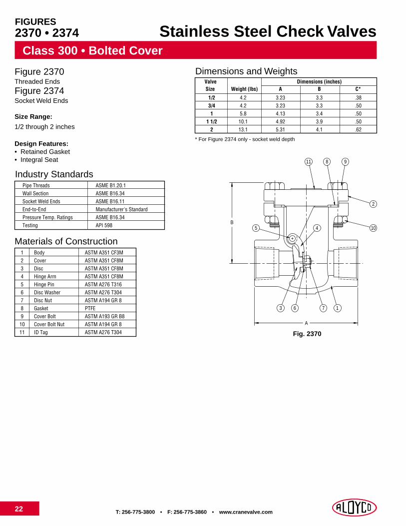
T: 256-775-3800 • F: 256-775-3860 • www.cranevalve.com22
Class 300 • Bolted Cover
Stainless Steel Check Valves
Figure 2370Threaded Ends
Figure 2374Socket Weld Ends
Size Range:
1/2 through 2 inches
Design Features:• Retained Gasket• Integral Seat
Industry StandardsPipe Threads ASME B1.20.1Wall Section ASME B16.34Socket Weld Ends ASME B16.11End-to-End Manufacturer's StandardPressure Temp. Ratings ASME B16.34Testing API 598
Materials of Construction1 Body ASTM A351 CF3M2 Cover ASTM A351 CF8M3 Disc ASTM A351 CF8M4 Hinge Arm ASTM A351 CF8M5 Hinge Pin ASTM A276 T3166 Disc Washer ASTM A276 T3047 Disc Nut ASTM A194 GR 88 Gasket PTFE9 Cover Bolt ASTM A193 GR B8
10 Cover Bolt Nut ASTM A194 GR 811 ID Tag ASTM A276 T304
Dimensions and WeightsValve Dimensions (inches)Size Weight (lbs) A B C*
1/2 4.2 3.23 3.3 .383/4 4.2 3.23 3.3 .501 5.8 4.13 3.4 .50
1 1/2 10.1 4.92 3.9 .502 13.1 5.31 4.1 .62
* For Figure 2374 only - socket weld depth
FIGURES2370 • 2374
B
A
3 6 7 1
2
811
5
9
104
Fig. 2370

T: 562-426-2531 • F: 562-490-9546 • www.cranevalve.com 23
Class 300 • Bolted CoverStainless Steel Check Valves
Figure 2377Raised Face, Flanged Ends
Size Range:
1/2 through 24 inches
Design Features:• Retained Gasket• Integral Seat• MSS-SP-42
Industry StandardsEnd Flanges ASME B16.5Wall Section ASME B16.34Face-to-Face ASME B16.10Pressure-Temp. Ratings ASME B16.34Testing API 598
Dimensions and WeightsValve Dimensions (inches)Size Weight (lbs) A B
1/2 --- 6.00 3.33/4 --- 7.00 3.31 --- 8.50 3.4
1 1/2 --- 9.50 3.92 --- 10.50 4.1
2 1/2 81.6 11.50 6.53 92.6 12.50 6.94 141.1 14.00 7.36 273.4 17.50 10.38 489.5 21.00 12.3
10 643.9 24.50 14.012 979.0 28.00 15.514 1420.0 33.00 20.116 1753.0 34.00 20.518 2319.7 38.50 22.520 2668.1 40.00 24.524 4224.8 53.00 28.0Materials of Construction
1 Body ASTM A351 CF8M2 Cover ASTM A351 CF8M3 Disc ASTM A351 CF8M4 Hinge Arm ASTM A351 CF8M5 Hinge Pin ASTM A276 T3166 Disc Washer ASTM A276 T3047 Disc Nut ASTM A194 GR 88 Gasket PTFE9 Cover Bolt ASTM A193 GR B8
10 Cover Bolt Nut ASTM A194 GR 811 ID Tag ASTM A276 T304
FIGURE2377
B
A
3 6 7 1
10
811 9
4
2
5
Fig. 2377

T: 256-775-3800 • F: 256-775-3860 • www.cranevalve.com24
Class 600 • Bolted Cover
Stainless Steel Check Valves
Figure 4370Threaded Ends
Figure 4374Socket Weld Ends
Size Range:
1/2 through 2 inches
Design Features:• Retained Gasket• Integral Seat
Industry StandardsPipe Threads ASME B1.20.1Wall Section ASME B16.34Socket Weld Ends ASME B16.11End-to-End Manufacturer's StandardPressure Temp. Ratings ASME B16.34Testing API 598
Materials of Construction1 Body ASTM A351 CF3M2 Cover ASTM A351 CF8M3 Disc ASTM A351 CF8M4 Hinge Arm ASTM A351 CF8M5 Hinge Pin ASTM A276 T3166 Disc Washer ASTM A276 T3047 Disc Nut ASTM A194 GR 88 Gasket PTFE9 Cover Bolt ASTM A193 GR B8
10 Cover Bolt Nut ASTM A194 GR 811 ID Tag ASTM A276 T304
Dimensions and WeightsValve Dimensions (inches)Size Weight (lbs) A B C*
1/2 4.2 3.23 3.3 .383/4 4.2 3.23 3.3 .501 5.8 4.13 3.4 .50
1 1/2 10.1 4.92 3.9 .502 13.1 5.31 4.1 .62
* For Figure 4374 only - socket weld depth
FIGURES4370 • 4374
B
A
3 6 7 1
2
811
5
9
104
Fig. 4370

T: 562-426-2531 • F: 562-490-9546 • www.cranevalve.com 25
Class 600 • Bolted CoverStainless Steel Check Valves
Figure 4377Raised Face, Flanged Ends
Size Range:
1/2 through 12 inches
Design Features:• Retained Gasket• Integral Seat• MSS SP-42
Industry StandardsEnd Flanges ASME B16.5Wall Section ASME B16.34Face-to-Face ASME B16.10Pressure-Temp. Ratings ASME B16.34Testing API 598
Dimensions and WeightsValve Dimensions (inches)Size Weight (lbs) A B
1/2 --- 6.50 3.33/4 --- 7.50 3.31 --- 8.50 3.4
1 1/2 --- 9.50 3.92 --- 11.50 4.1
2 1/2 108.0 13.00 7.93 123.5 14.00 8.34 227.1 17.00 10.16 449.8 22.00 13.08 754.1 26.00 14.310 1375.9 31.00 18.312 1711.1 33.00 19.1
Materials of Construction1 Body ASTM A351 CF8M2 Cover ASTM A351 CF8M3 Disc ASTM A351 CF8M4 Hinge Arm ASTM A351 CF8M5 Hinge Pin ASTM A276 T3166 Disc Washer ASTM A276 T3047 Disc Nut ASTM A194 GR 88 Gasket PTFE9 Cover Bolt ASTM A193 GR B8
10 Cover Bolt Nut ASTM A194 GR 811 ID Tag ASTM A276 T304
FIGURE4377
B
A
3 6 7 1
10
811 9
4
2
5
Fig. 4377

T: 256-775-3800 • F: 256-775-3860 • www.cranevalve.com26
Stainless Steel Ball Valves
Figure 9502Threaded Ends
Size Range:1/4 through 2 inches
Design Features:• MSS SP-110• Full Port• Locking Handle• Standard Mounting Pad• Firesafe to API 607
Materials of Construction1 Body CF8M2 End Cap CF8M3 Gasket Graphite4 Body Seal Teflon5 Seats RPTFE6 Ball CF8M7 Stem Type 3168 Thrust Washer RPTFE9 Stem Packing Graphite
10 Gland Nut 304SS11 Stem Washer 304SS12 Stem Nut 304SS13 Handle 304SS14 Locking Device 304SS
ValveSize
Dimensions and Weights Dimensions (inches)
Weight (lbs) OD L H E G1 G2 T
1/4 0.7 0.36 2.11 1.86 3.82 0.50 1.12 M53/8 0.7 0.36 2.11 1.86 3.82 0.50 1.12 M51/2 1.1 0.50 2.66 2.08 4.33 0.50 1.12 M53/4 1.8 0.75 2.97 2.23 4.33 0.87 1.37 M51 2.6 1.00 3.50 2.74 5.57 0.87 1.37 M5
1 1/4 3.3 1.25 3.96 2.94 5.57 0.93 1.50 M51 1/2 4.4 1.50 4.45 3.22 6.50 0.93 1.50 M6
2 9.5 2.00 5.18 4.42 10.04 0.93 1.50 M6
2000 CWP • Two-Piece Body
FIGURE9502
Fig. 9502

T: 562-426-2531 • F: 562-490-9546 • www.cranevalve.com 27
Materials of Construction
Composition, %ASTM A351 ASTM A494
Element CF8M CF3M CN7M M-35-1 CW-12MWCarbon 0.08 0.03 0.07 0.35 0.12Chromium 18.0 - 21.0 17.0 - 21.0 19.0 - 22.0 0.00 15.5 - 17.5Columbium (Niobium) 0.00 0.00 0.00 0.50 0.00Copper 0.00 0.00 3.0 - 4.0 26.0 - 33.0 0.00Iron 0.00 0.00 0.00 3.50 4.5 - 7.5Manganese 1.50 1.50 1.50 1.50 1.00Molybdenum 2.0 - 3.0 2.0 - 3.0 2.0 - 3.0 0.00 16.0 - 18.0Nickel 9.0 - 12.0 9.0 - 13.0 27.5 - 30.5 balance balancePhosphorus 0.04 0.04 0.04 0.03 0.04Silicon 1.50 1.50 1.50 1.25 1.00Sulfur 0.04 0.04 0.04 0.03 0.03Tungsten 0.00 0.00 0.00 0.00 3.75 - 5.25Vanadium 0.00 0.00 0.00 0.00 0.20 - 0.40
Assume all values are maximum, unless a range is given
Tensile Requirements Mechanical PropertiesTensile Strength 70,000 70,000 62,000 65,000 72,000Yield Strength 30,000 30,000 25,000 25,000 40,000Elongation in 2 inches, % 30.0% 30.0% 35.0% 25.0% 4.0%

T: 256-775-3800 • F: 256-775-3860 • www.cranevalve.com28
Pressure Temperature
ASTM A351 Gr. CF8M ASTM A351 Gr. CF3M ASTM A351 Gr. CN7M ASTM A494 M-35-1 ASTM A494 Gr. CW-12MWTemp °F Working Pressure (psig) Working Pressure (psig) Working Pressure (psig) Working Pressure (psig) Working Pressure (psig)
CL. 150 CL. 300 CL. 600 CL. 150 CL. 300 CL. 600 CL. 150 CL. 300 CL. 600 CL. 150 CL. 300 CL. 600 CL. 150 CL. 300 CL. 600
-20 to 100 275 720 1,440 230 600 1,220 230 600 1,200 230 600 N/A 230 600 1,200200 235 620 1,240 195 505 1,015 200 520 1,045 200 525 N/A 205 540 1,080300 215 560 1,120 175 455 910 190 490 980 190 490 N/A 195 505 1,015400 195 515 1,025 160 415 825 190 490 980 180 475 N/A 185 480 960500 170 480 955 145 380 765 170 490 980 170 470 N/A 170 455 910600 140 450 900 140 360 720 140 490 980 140 470 N/A 140 440 880650 125 445 890 125 350 700 125 490 980 125 435 N/A 125 425 850700 110 430 870 110 345 685 110 490 980 110 405 N/A 110 420 840750 95 425 855 95 335 670 95 490 980 95 405 N/A 95 415 825800 80 420 845 80 330 660 80 490 980 80 405 N/A 80 410 815850 65 420 835 65 320 645 65 325 N/A 65 400 795900 50 415 830 50 245 N/A 50 395 790950 35 385 775 25 120 N/A 35 385 7751000 20 350 700 20 365 7251050 20 * 345 6851100 20 * 305 6101150 20 * 235 4751200 20 * 185 3701250 20 * 145 2951300 20 * 115 2351350 20 * 95 1901400 20 * 75 1501450 20 * 60 1151500 15 * 40 85
* Rating for weld-end valves. Use solution annealed material onlyFlanged End valves rated to 1000°F maximum Not to be used over 1000°F maximum
Hydrostatic Shell Test Pressures
Class 150 300 600Pressure 425 1,100 2,175
NOTE: These are design pressure ratings from ASME B16.34-1996 and apply to castings only. Packing and gasket materials may limit temperature range of specific products.

T: 562-426-2531 • F: 562-490-9546 • www.cranevalve.com 29
Stainless Steel ValvesValve Marking System
ALOYCO
CCC
AAAA
FRONT BACK
GGGGGG
DDD
EEEEEEEEEEE
AAAA FF GGGGGG
FFBBB
It is important to properly identify valves in service to allow for the ordering of replacement parts or to address questions orconcerns relating to Aloyco products. The valve marking system shown here will help customers identify valves accurately,speeding responses to customer service issues.
Valve Marking System Codes
AAAA Material (CF3M, CF8M, etc.)
BBB Size (1/2", 4", etc.)
CCC Class (150, 300, 600)
DDD Manufacturer ID Number
EEEEEEEEEE Serial Number
FF Foundry Number
GGGGGG Heat Number
Gate Valve

T: 256-775-3800 • F: 256-775-3860 • www.cranevalve.com30
Stainless Steel ValvesValve Marking System
ALOYCO
CCC
AAAA
FRONT BACK
GGGGGG
DDD
EEEEEEEEEEE
AAAA FF GGGGGG
FFBBB
ALOYCO
CCC
AAAA
FRONT BACK
GGGGGG
DDD
EEEEEEEEEEE
AAAA FF GGGGGG
FFBBB
Globe Valve
Check Valve

CV-203
“We wrote the book”
Aloyco2129 3rd Avenue, S.E.Cullman, AL 35055Tel: 800-786-2542Fax: 256-775-3860
www.cranevalve.comAloyco is a trademark of Crane Co.