Embed Size (px)
Citation preview

Author’s post-print: Antonio Navarro-Manso, Juan José del Coz Díaz, Mar Alonso-Martínez, Daniel Castro-Fresno and Felipe Pedro Alvarez Rabanal. “Patch loading in slender and high depth steel panels: fem - doe analyses and bridge launching application” Engineering Structures 83 (2015) 74–85. http://dx.doi.org/10.1016/j.engstruct.2014.10.051
1
PATCH LOADING IN SLENDER AND HIGH DEPTH STEEL PANELS: FEM - 1
DOE ANALYSES AND BRIDGE LAUNCHING APPLICATION 2
Antonio Navarro-Manso1 Juan José del Coz Díaz2*, Mar 3
Alonso-Martínez2, Daniel Castro-Fresno3 and Felipe Pedro 4
Alvarez Rabanal2 5 6
1 Department of Energy, University of Oviedo, 33204 Gijón (Spain) 7 8 2 Department of Construction, EPSIII, University of Oviedo, 33204 Gijón (Spain) 9
10 3 GITECO Research Group, ETSICCP, University of Cantabria, 39005 Santander 11
(Spain) 12
13
14
1. Introduction 15
16
The bridge launching construction system assembles the deck of the bridge in a location 17
or position different than the definitive one; by means of adding successive segments, the 18
deck is launched forward on the piers and other supplementary supports. Many auxiliary 19
systems are usually used with the aim of resisting the huge forces in the cantilever section 20
(bending and torsional -if any- forces and point loads); as well as pushing systems to 21
propel the deck forward (see Fig. 1). 22
23
This method allows the construction of the bridge to be highly independent of the ground 24
conditions. The launching method (today Incremental Launching Method, ILM) was 25
developed in Europe in the Nineteenth Century, as it was exposed in some research works 26
and Thesis [1]. This erection method was applied mostly to steel bridges (e.g. Neuvial 27
Viaduct, by G. Eiffel, 1869, France). Nevertheless it was not until the mid-Twentieth 28
Century that the best examples were constructed. The Caroni Bridge, over the Caroni 29
River in Venezuela built in 1961, by Leonhardt and Baur, is considered to be the first 30
modern application of this method, launching in this case a concrete bridge. The patent 31
of this method is dated to 1967 [2]. 32
33
* Corresponding Author: Prof. Juan José del Coz Díaz
Email: [email protected]

Author’s post-print: Antonio Navarro-Manso, Juan José del Coz Díaz, Mar Alonso-Martínez, Daniel Castro-Fresno and Felipe Pedro Alvarez Rabanal. “Patch loading in slender and high depth steel panels: fem - doe analyses and bridge launching application” Engineering Structures 83 (2015) 74–85. http://dx.doi.org/10.1016/j.engstruct.2014.10.051
2
34 Fig.1. Launching conventional method scheme with nose and cable pulling system 35
(courtesy of VSL Ltd.). 36
37
1.1 Bridge launching present disadvantages 38
39
Despite this method’s multiple advantages, which have led this system to become 40
widespread all over the world in the past three decades, the method presents some 41
problems that may make it less competitive compared to other construction systems, 42
depending on the bridge and site characteristics. 43
44
State of the Art methods [3,4] have presented a wide range of alternatives for launching 45
bridges. The limitations of those techniques are described below: 46
47
- The structure is subjected to two very different resistance schemes: the cantilever 48
beam during the construction stages and the continuous beam during the service 49
life. Usually Serviceability Limit States (SLS) during construction are more 50
restrictive than the final conditions [5]. 51
- Every section must resist alternate sign bending forces and patch loading, even 52
the sections that have not been designed to do so when the construction is 53
completed. This is a critical factor in designing the first two spans of the bridge 54
[6]. 55
- There is some preparation time because of the need to set up the auxiliary and 56
pushing systems, and the launching speed is not fast [7]. 57
- It is difficult to have a good safety system in order to control or monitor reactions 58
on every support during the launching, and to achieve the compensation of the 59
load is not currently available [8]. 60
- This construction method is not very sustainable because it uses a lot of non-61
reusable materials [9]. 62
- Finally, safety is sometimes compromised because the current pushing system is 63
not reversible and does not allow the deck to retract fast and easily [10]. 64
65
2. The new launching method 66
67
The new method for bridge launching is patent-protected [11,12] and allows the use of 68
longer spans, which are easier and cheaper than the ones used nowadays. The main issue 69
Author’s post-print: Antonio Navarro-Manso, Juan José del Coz Díaz, Mar Alonso-Martínez, Daniel Castro-Fresno and Felipe Pedro Alvarez Rabanal. “Patch loading in slender and high depth steel panels: fem - doe analyses and bridge launching application” Engineering Structures 83 (2015) 74–85. http://dx.doi.org/10.1016/j.engstruct.2014.10.051
3
in such structures is related to the patch loading phenomenon that may produce the 70
instability of slender steel webs. 71
72
2.1 Patch loading solutions in conventional ILM 73
74
The 150 m long cantilever presented in this paper implies a huge point load directly on 75
the supports of the first pier. This action is named patch loading in the specialized 76
literature and it is one of most important design problems when regarding slender steel 77
plates, because the yield resistance of the steel cannot be fully taken into account and 78
instability phenomena, like buckling, drastically decrease the ultimate load that panels 79
can resist. 80
81
The most important factor that contributes to resist point loads is the thickness of the web. 82
Other parameters that have an influence on the patch loading phenomenon are the position 83
of the support with respect to the web axis, the stiffeners located all along the deck, the 84
disposition of transversal frames and the steel strength. 85
86
The benefits of designing longitudinal and vertical stiffeners are well known, thus the 87
steel plate is divided into sub-panels that can reduce the transversal displacement. Almost 88
all the international codes and rules need to adopt simplifications in order to attain an 89
expression that could be useful. This is one of the reasons why these expressions must be 90
checked through experimental data, testing different boundary conditions of the steel 91
plate, several ways to apply the load, etc. 92
93
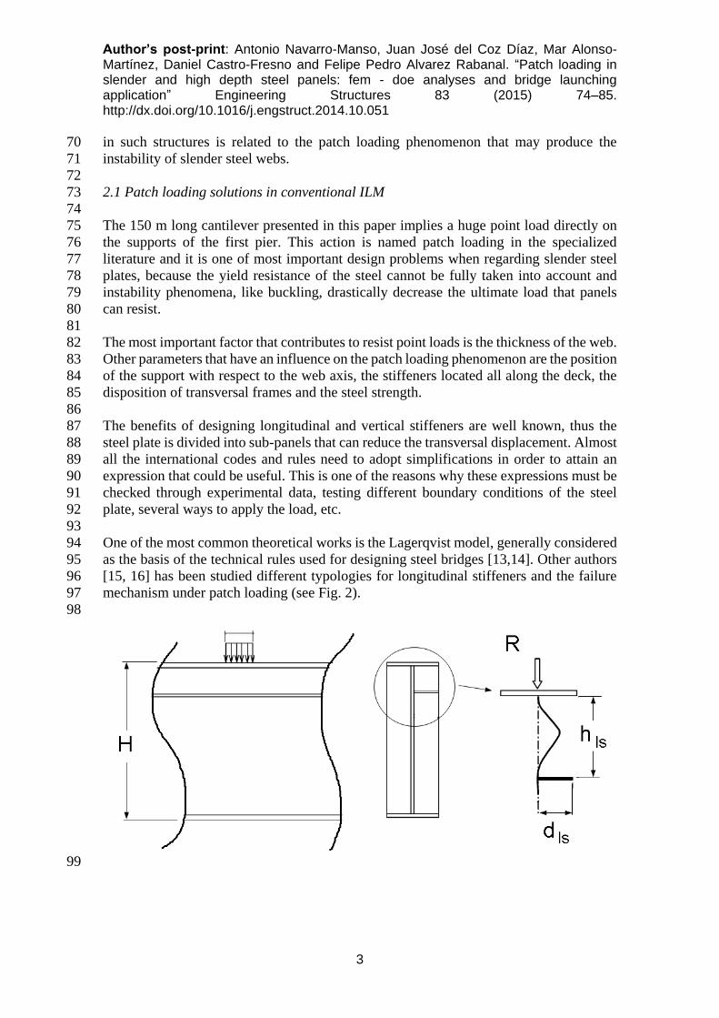
One of the most common theoretical works is the Lagerqvist model, generally considered 94
as the basis of the technical rules used for designing steel bridges [13,14]. Other authors 95
[15, 16] has been studied different typologies for longitudinal stiffeners and the failure 96
mechanism under patch loading (see Fig. 2). 97
98
99
Author’s post-print: Antonio Navarro-Manso, Juan José del Coz Díaz, Mar Alonso-Martínez, Daniel Castro-Fresno and Felipe Pedro Alvarez Rabanal. “Patch loading in slender and high depth steel panels: fem - doe analyses and bridge launching application” Engineering Structures 83 (2015) 74–85. http://dx.doi.org/10.1016/j.engstruct.2014.10.051
4
Fig. 2. Typical failure mechanism of longitudinally stiffened slender girder under patch 100
loading. 101
102
However these methods and experimental data cannot accurately solve special 103
configurations, like the configuration hereby described containing the triangular cell 104
neither the actual boundary conditions nor the influence of longitudinal and transversal 105
stiffeners in a high depth steel plate under the huge patch loading and bending moment 106
actions; nor the interaction of all the phenomena involved [17,18]. 107
108
2.2 Description of the proposal 109
110
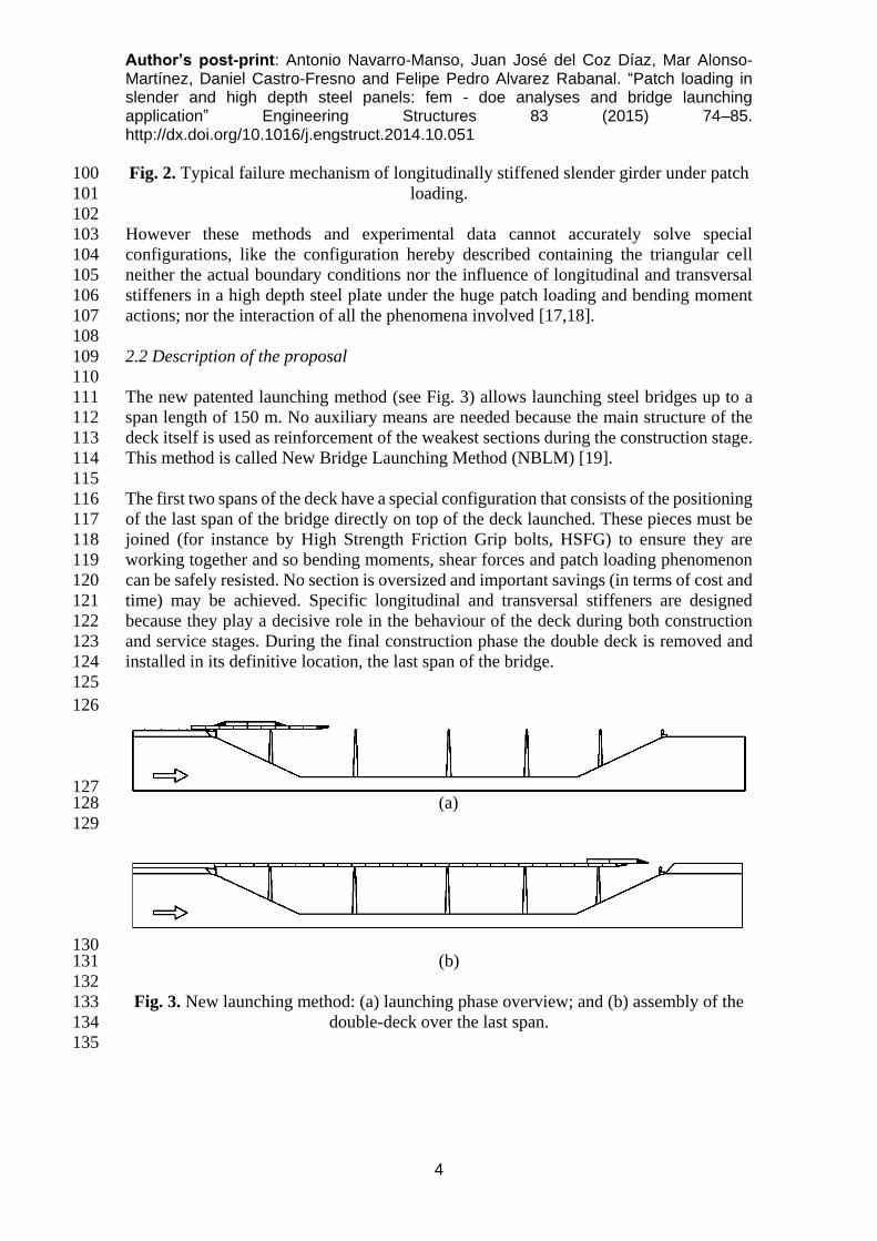
The new patented launching method (see Fig. 3) allows launching steel bridges up to a 111
span length of 150 m. No auxiliary means are needed because the main structure of the 112
deck itself is used as reinforcement of the weakest sections during the construction stage. 113
This method is called New Bridge Launching Method (NBLM) [19]. 114
115
The first two spans of the deck have a special configuration that consists of the positioning 116
of the last span of the bridge directly on top of the deck launched. These pieces must be 117
joined (for instance by High Strength Friction Grip bolts, HSFG) to ensure they are 118
working together and so bending moments, shear forces and patch loading phenomenon 119
can be safely resisted. No section is oversized and important savings (in terms of cost and 120
time) may be achieved. Specific longitudinal and transversal stiffeners are designed 121
because they play a decisive role in the behaviour of the deck during both construction 122
and service stages. During the final construction phase the double deck is removed and 123
installed in its definitive location, the last span of the bridge. 124
125
126
127 (a) 128
129
130 (b) 131
132
Fig. 3. New launching method: (a) launching phase overview; and (b) assembly of the 133
double-deck over the last span. 134
135
Author’s post-print: Antonio Navarro-Manso, Juan José del Coz Díaz, Mar Alonso-Martínez, Daniel Castro-Fresno and Felipe Pedro Alvarez Rabanal. “Patch loading in slender and high depth steel panels: fem - doe analyses and bridge launching application” Engineering Structures 83 (2015) 74–85. http://dx.doi.org/10.1016/j.engstruct.2014.10.051
5
The system described and shown above is completed with other mechanisms, such as the 136
small nose to reduce and regain the deflection during the largest launching phase, 137
disconnection system of the double-deck and the new device for continuous bridge 138
launching [20]. 139
140
2.3 Advantages 141
142
The main advantages of the new method are the following [19,21]: 143
144
- Critical sections, mostly those belonging to the first span during the launching, do 145
not have to be oversized with respect to requirements of the serviceability limit 146
state. 147
- Launched span is increased and no auxiliary means are needed. 148
- Material is more efficiently and sustainably used, only when it is needed. 149
- Torsional behavior of the deck, and the general structural behavior, during the 150
launching are improved; even when curved geometries are assembled. 151
- The construction process involves simple and repetitive operations that can be 152
monitored. The increasing of the span allows the protection of the environmental 153
surroundings of the location. All of this leads to a lower execution time and costs, 154
as well as to a better quality of work. 155
156
3. Numerical models 157
158
The numerical simulation was carried out using a nonlinear finite element model (FEM). 159
The structural response of the basic parts making up the bridge is understood in great 160
detail thanks to this simulation technique, saving costs and time in relation to tests [22]. 161
162
Only the first two spans of the bridge are modeled since the behavior of the whole deck 163
can be simulated accurately by adding the corresponding boundary conditions. The FEM 164
model used includes the main cantilever span of 150 m and the adjacent span from pier 165
nº 1 to the abutment. So this model corresponds to the critical phase launching and is 280 166
m long. 167
168
3.1 Finite element model 169
170
The FE model in this work has been based on the ANSYS software [22], using the 171
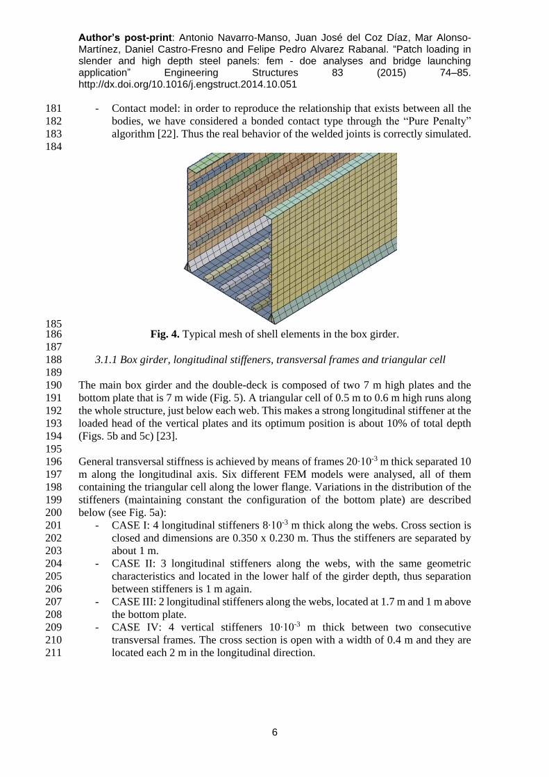
following element types and contacts (see Fig. 4): 172
- SHELL 181 is a kind of element used to model thin walled structures, like steel 173
plates (including webs, flanges and stiffeners). It is well suited for linear, large 174
rotation, and/or large deflection nonlinear applications and is a three-dimensional 175
four node finite element having six degrees of freedom per node: translations and 176
rotations in the nodal X, Y, and Z directions. 177
- The finite element SOLID186, used to model the plates of the bearings, is a higher 178
order 3D 20-node solid that exhibits quadratic displacement performance having 179
three degrees of freedom per node: translations in the nodal X, Y, and Z directions. 180
Author’s post-print: Antonio Navarro-Manso, Juan José del Coz Díaz, Mar Alonso-Martínez, Daniel Castro-Fresno and Felipe Pedro Alvarez Rabanal. “Patch loading in slender and high depth steel panels: fem - doe analyses and bridge launching application” Engineering Structures 83 (2015) 74–85. http://dx.doi.org/10.1016/j.engstruct.2014.10.051
6
- Contact model: in order to reproduce the relationship that exists between all the 181
bodies, we have considered a bonded contact type through the “Pure Penalty” 182
algorithm [22]. Thus the real behavior of the welded joints is correctly simulated. 183
184
185 Fig. 4. Typical mesh of shell elements in the box girder. 186
187
3.1.1 Box girder, longitudinal stiffeners, transversal frames and triangular cell 188
189
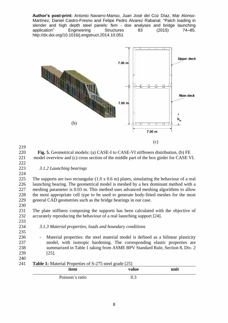
The main box girder and the double-deck is composed of two 7 m high plates and the 190
bottom plate that is 7 m wide (Fig. 5). A triangular cell of 0.5 m to 0.6 m high runs along 191
the whole structure, just below each web. This makes a strong longitudinal stiffener at the 192
loaded head of the vertical plates and its optimum position is about 10% of total depth 193
(Figs. 5b and 5c) [23]. 194
195
General transversal stiffness is achieved by means of frames 20∙10-3 m thick separated 10 196
m along the longitudinal axis. Six different FEM models were analysed, all of them 197
containing the triangular cell along the lower flange. Variations in the distribution of the 198
stiffeners (maintaining constant the configuration of the bottom plate) are described 199
below (see Fig. 5a): 200
- CASE I: 4 longitudinal stiffeners 8∙10-3 m thick along the webs. Cross section is 201
closed and dimensions are 0.350 x 0.230 m. Thus the stiffeners are separated by 202
about 1 m. 203
- CASE II: 3 longitudinal stiffeners along the webs, with the same geometric 204
characteristics and located in the lower half of the girder depth, thus separation 205
between stiffeners is 1 m again. 206
- CASE III: 2 longitudinal stiffeners along the webs, located at 1.7 m and 1 m above 207
the bottom plate. 208
- CASE IV: 4 vertical stiffeners 10∙10-3 m thick between two consecutive 209
transversal frames. The cross section is open with a width of 0.4 m and they are 210
located each 2 m in the longitudinal direction. 211

Author’s post-print: Antonio Navarro-Manso, Juan José del Coz Díaz, Mar Alonso-Martínez, Daniel Castro-Fresno and Felipe Pedro Alvarez Rabanal. “Patch loading in slender and high depth steel panels: fem - doe analyses and bridge launching application” Engineering Structures 83 (2015) 74–85. http://dx.doi.org/10.1016/j.engstruct.2014.10.051
7
- CASE V: 2 vertical stiffeners between two consecutive transversal frames, with 212
the same settings, separated by 3.33 m 213
- CASE VI: 1 longitudinal stiffener along the webs and 2 vertical stiffeners between 214
two consecutive transversal frames. The characteristics of each stiffener have 215
already been described and the longitudinal stiffener is 2 m above the bottom 216
plate. 217
218
(a)
Author’s post-print: Antonio Navarro-Manso, Juan José del Coz Díaz, Mar Alonso-Martínez, Daniel Castro-Fresno and Felipe Pedro Alvarez Rabanal. “Patch loading in slender and high depth steel panels: fem - doe analyses and bridge launching application” Engineering Structures 83 (2015) 74–85. http://dx.doi.org/10.1016/j.engstruct.2014.10.051
8
(b)
(c)
219
Fig. 5. Geometrical models: (a) CASE-I to CASE-VI stiffeners distribution, (b) FE 220
model overview and (c) cross section of the middle part of the box girder for CASE VI. 221
222
3.1.2 Launching bearings 223
224
The supports are two rectangular (1.0 x 0.6 m) plates, simulating the behaviour of a real 225
launching bearing. The geometrical model is meshed by a hex dominant method with a 226
meshing parameter is 0.03 m. This method uses advanced meshing algorithms to allow 227
the most appropriate cell type to be used to generate body-fitted meshes for the most 228
general CAD geometries such as the bridge bearings in our case. 229
230
The plate stiffness composing the supports has been calculated with the objective of 231
accurately reproducing the behaviour of a real launching support [24]. 232
233
3.1.3 Material properties, loads and boundary conditions 234
235
- Material properties: the steel material model is defined as a bilinear plasticity 236
model, with isotropic hardening. The corresponding elastic properties are 237
summarized in Table 1 taking from ASME BPV Standard Rule, Section 8, Div. 2 238
[25]. 239
240
Table 1: Material Properties of S-275 steel grade [25] 241
item value unit
Poisson´s ratio 0.3
Author’s post-print: Antonio Navarro-Manso, Juan José del Coz Díaz, Mar Alonso-Martínez, Daniel Castro-Fresno and Felipe Pedro Alvarez Rabanal. “Patch loading in slender and high depth steel panels: fem - doe analyses and bridge launching application” Engineering Structures 83 (2015) 74–85. http://dx.doi.org/10.1016/j.engstruct.2014.10.051
9
Elastic modulus 2∙1011 Pa
Elastic yield strength 250 MPa
Tensile ultimate strength 460 MPa
Tangent modulus 10,000 MPa
242
243
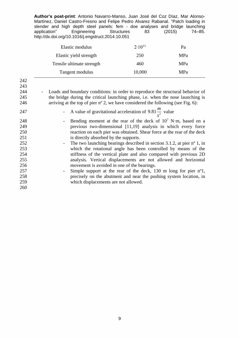
- Loads and boundary conditions: in order to reproduce the structural behavior of 244
the bridge during the critical launching phase, i.e. when the nose launching is 245
arriving at the top of pier nº 2, we have considered the following (see Fig. 6): 246
- A value of gravitational acceleration of 2
9.81m
s value 247
- Bending moment at the rear of the deck of 107 N·m, based on a 248
previous two-dimensional [11,19] analysis in which every force 249
reaction on each pier was obtained. Shear force at the rear of the deck 250
is directly absorbed by the supports. 251
- The two launching bearings described in section 3.1.2, at pier nº 1, in 252
which the rotational angle has been controlled by means of the 253
stiffness of the vertical plate and also compared with previous 2D 254
analysis. Vertical displacements are not allowed and horizontal 255
movement is avoided in one of the bearings. 256
- Simple support at the rear of the deck, 130 m long for pier nº1, 257
precisely on the abutment and near the pushing system location, in 258
which displacements are not allowed. 259
260
Author’s post-print: Antonio Navarro-Manso, Juan José del Coz Díaz, Mar Alonso-Martínez, Daniel Castro-Fresno and Felipe Pedro Alvarez Rabanal. “Patch loading in slender and high depth steel panels: fem - doe analyses and bridge launching application” Engineering Structures 83 (2015) 74–85. http://dx.doi.org/10.1016/j.engstruct.2014.10.051
10
261 Fig. 6. Boundary conditions applied to the model. 262
263
3.2 Numerical analysis of the structural system 264
265
The present nonlinear static structural problem was solved by using the full Newton-266
Raphson option for all degrees of freedom with a non-symmetric solver including the 267
adaptive descent option. With the aim of achieving an initial solution for the lineal 268
buckling analysis it was necessary to perform a linear static structural analysis. Then a 269
linear buckling analysis was undertaken and the normalized values of the initial defect of 270
each mode were calculated. Finally, the plasticity of the material and actualization of the 271
geometry in every step load was taken into account to obtain the failure load. To ensure 272
the convergence of the results, the Newton-Raphson analysis options for a time step of 1 273
second, neglecting the inertial effects, are summarized in Table 2: 274
275
Table 2: Newton-Raphson analysis setting options for a time step of 1 second. 276
Item value

Author’s post-print: Antonio Navarro-Manso, Juan José del Coz Díaz, Mar Alonso-Martínez, Daniel Castro-Fresno and Felipe Pedro Alvarez Rabanal. “Patch loading in slender and high depth steel panels: fem - doe analyses and bridge launching application” Engineering Structures 83 (2015) 74–85. http://dx.doi.org/10.1016/j.engstruct.2014.10.051
11
Initial Time Step [s] 0.1
Min Time Step [s] 0.001
Max Time Step [s] 0.1
277
278
A force tolerance value of 0.5% was considered with a minimum value of 0.01 N for 279
stabilising the solution. The problem was solved on an INTEL Core i-7 64 bits processor, 280
with 12 GB of RAM and 4 TB of hard drive. The CPU total time in each load case varied 281
from 2.000 to 8.000 seconds for the full simulation of every case. 282
283
3.2.1 Linear Buckling Analysis 284
285
In this section the six cases with different stiffener distributions are calculated, in order 286
to complete the design of the deck that is going to be launched. The numerical model used 287
to calculate the deck stiffness and to considerer the non-linear effects includes the 288
optimum triangular cell and the double deck system, both were mentioned above. 289
290
The model used for the analysis is supported by means of two provisional launching 291
bearings described previously and they are located on pier nº1 at 145 m from the nose. 292
This is the most critical launching phase in which the nose gets closer to pier nº 2 and the 293
support bearings are located directly in the middle of two transversal frames. This 294
condition will be investigated in the final design in order to assess the most critical 295
location of the supports. 296
297
The linear buckling problem is solved by Equation (1), and the eigenvalues are obtained: 298
299
0i iK S (1) 300
301
where 𝜆𝑖 are the load factors of each buckling mode, K and S are stiffness and stress 302
sate matrices, respectively, and i is the matrix displacement of the structure. 303
304
The critical load Picri
of each buckling mode is obtained the following expression (2), 305
where load factor increases with the maximum load iP : 306
307
Pi× l
i= P
icri
(2) 308
309
The first buckling modes affecting the web and their corresponding load factors are 310
represented in the Fig. 7, for each case previously defined. In each case, fourty buckling 311
modes were calculated using the Lanczos algorithm, in order to achieve enough precision 312
during the non-linear analysis. 313

Author’s post-print: Antonio Navarro-Manso, Juan José del Coz Díaz, Mar Alonso-Martínez, Daniel Castro-Fresno and Felipe Pedro Alvarez Rabanal. “Patch loading in slender and high depth steel panels: fem - doe analyses and bridge launching application” Engineering Structures 83 (2015) 74–85. http://dx.doi.org/10.1016/j.engstruct.2014.10.051
12
314

Author’s post-print: Antonio Navarro-Manso, Juan José del Coz Díaz, Mar Alonso-Martínez, Daniel Castro-Fresno and Felipe Pedro Alvarez Rabanal. “Patch loading in slender and high depth steel panels: fem - doe analyses and bridge launching application” Engineering Structures 83 (2015) 74–85. http://dx.doi.org/10.1016/j.engstruct.2014.10.051
13
315
Author’s post-print: Antonio Navarro-Manso, Juan José del Coz Díaz, Mar Alonso-Martínez, Daniel Castro-Fresno and Felipe Pedro Alvarez Rabanal. “Patch loading in slender and high depth steel panels: fem - doe analyses and bridge launching application” Engineering Structures 83 (2015) 74–85. http://dx.doi.org/10.1016/j.engstruct.2014.10.051
14
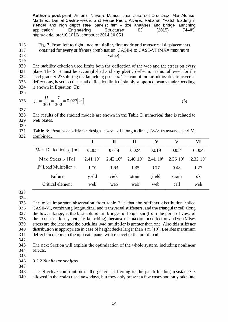
Fig. 7. From left to right, load multiplier, first mode and transversal displacements 316
obtained for every stiffeners combination, CASE-I to CASE-VI (MX= maximum 317
value). 318
319
The stability criterion used limits both the deflection of the web and the stress on every 320
plate. The SLS must be accomplished and any plastic deflection is not allowed for the 321
steel grade S-275 during the launching process. The condition for admissible transversal 322
deflections, based on the usual deflection limit of simply supported beams under bending, 323
is shown in Equation (3): 324
325
7
0.023300 300
w
Hf m (3) 326
327
The results of the studied models are shown in the Table 3, numerical data is related to 328
web plates. 329
330
Table 3: Results of stiffener design cases: I-III longitudinal, IV-V transversal and VI 331
combined. 332
I II III IV V VI
Max. Deflection wf [m] 0.005 0.014 0.024 0.019 0.034 0.004
Max. Stress [Pa] 2.41·108 2.43·108 2.40·108 2.41·108 2.36·108 2.32·108
1st Load Multiplier i 1.70 1.63 1.35 0.77 0.48 1.27
Failure yield yield strain yield strain ok
Critical element web web web web cell web
333
334
The most important observation from table 3 is that the stiffener distribution called 335
CASE-VI, combining longitudinal and transversal stiffeners, and the triangular cell along 336
the lower flange, is the best solution in bridges of long span (from the point of view of 337
their construction system, i.e. launching), because the maximum deflection and von Mises 338
stress are the least and the buckling load multiplier is greater than one. Also this stiffener 339
distribution is appropriate in case of height decks larger than 4 m [10]. Besides maximum 340
deflection occurs in the opposite panel with respect to the point load. 341
342
The next Section will explain the optimization of the whole system, including nonlinear 343
effects. 344
345
3.2.2 Nonlinear analysis 346
347
The effective contribution of the general stiffening to the patch loading resistance is 348
allowed in the codes used nowadays, but they only present a few cases and only take into 349
Author’s post-print: Antonio Navarro-Manso, Juan José del Coz Díaz, Mar Alonso-Martínez, Daniel Castro-Fresno and Felipe Pedro Alvarez Rabanal. “Patch loading in slender and high depth steel panels: fem - doe analyses and bridge launching application” Engineering Structures 83 (2015) 74–85. http://dx.doi.org/10.1016/j.engstruct.2014.10.051
15
account the buckling of the directly loaded panel. In consequence the practical solution 350
may be rather conservative or not correctly understood. So the non-linear analysis 351
described in this paper can solve the buckling problem of the real case, accurately 352
obtaining the collapsing load [25,26]. 353
354
Once the linear buckling analysis has been carried out, the Case VI is selected to be solved 355
under non-linear conditions. Eighteen linear buckling modes were combined by means of 356
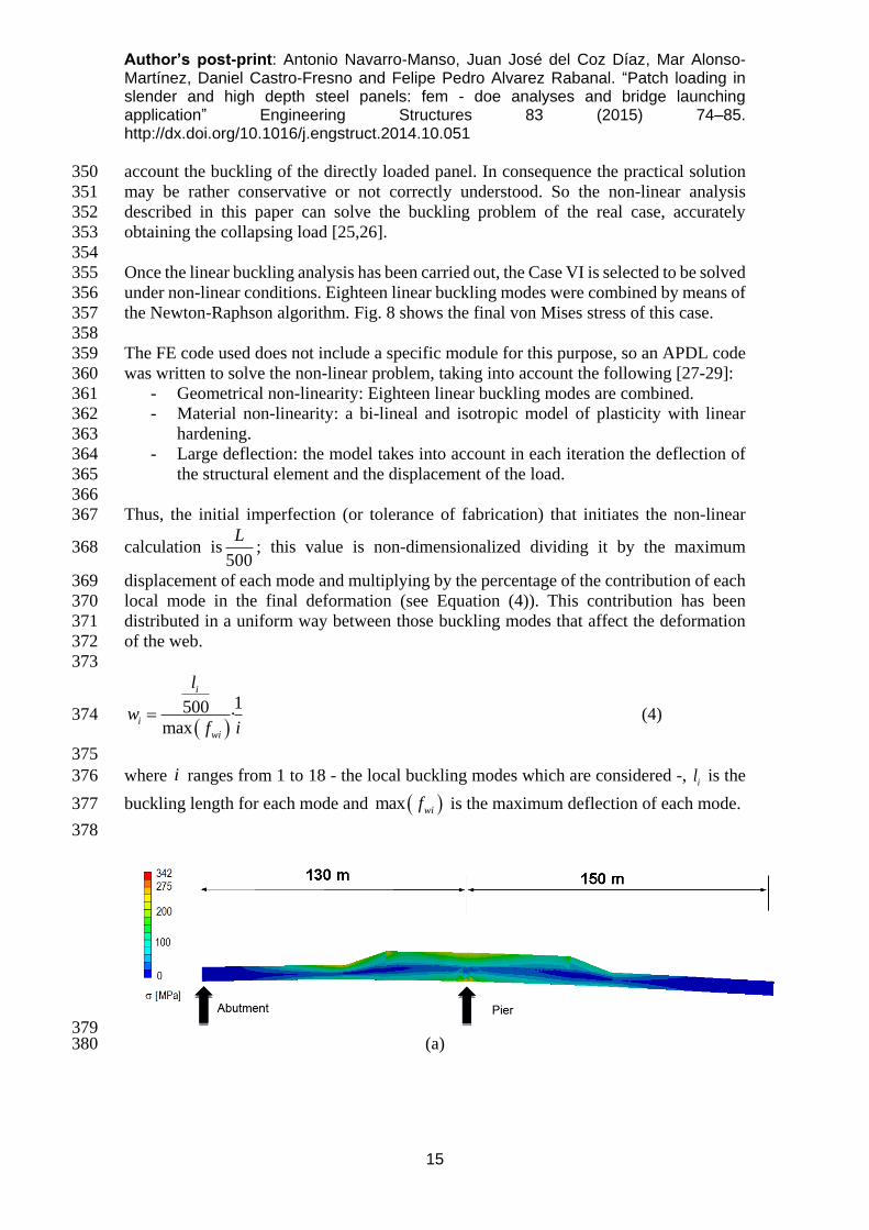
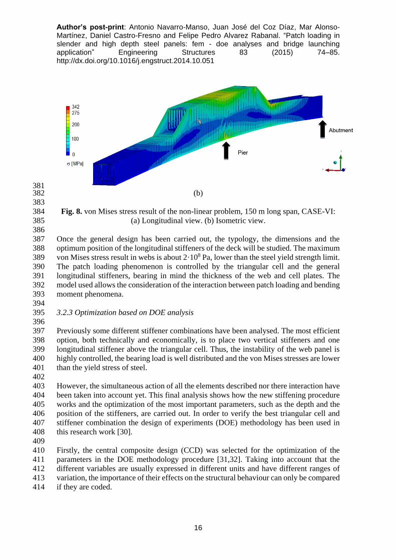
the Newton-Raphson algorithm. Fig. 8 shows the final von Mises stress of this case. 357
358
The FE code used does not include a specific module for this purpose, so an APDL code 359
was written to solve the non-linear problem, taking into account the following [27-29]: 360
- Geometrical non-linearity: Eighteen linear buckling modes are combined. 361
- Material non-linearity: a bi-lineal and isotropic model of plasticity with linear 362
hardening. 363
- Large deflection: the model takes into account in each iteration the deflection of 364
the structural element and the displacement of the load. 365
366
Thus, the initial imperfection (or tolerance of fabrication) that initiates the non-linear 367
calculation is500
L; this value is non-dimensionalized dividing it by the maximum 368
displacement of each mode and multiplying by the percentage of the contribution of each 369
local mode in the final deformation (see Equation (4)). This contribution has been 370
distributed in a uniform way between those buckling modes that affect the deformation 371
of the web. 372
373
1500 ·
max
i
i
wi
l
wf i
(4) 374
375
where i ranges from 1 to 18 - the local buckling modes which are considered -, il is the 376
buckling length for each mode and max wif is the maximum deflection of each mode. 377
378
379 (a) 380
Author’s post-print: Antonio Navarro-Manso, Juan José del Coz Díaz, Mar Alonso-Martínez, Daniel Castro-Fresno and Felipe Pedro Alvarez Rabanal. “Patch loading in slender and high depth steel panels: fem - doe analyses and bridge launching application” Engineering Structures 83 (2015) 74–85. http://dx.doi.org/10.1016/j.engstruct.2014.10.051
16
381 (b) 382
383
Fig. 8. von Mises stress result of the non-linear problem, 150 m long span, CASE-VI: 384
(a) Longitudinal view. (b) Isometric view. 385
386
Once the general design has been carried out, the typology, the dimensions and the 387
optimum position of the longitudinal stiffeners of the deck will be studied. The maximum 388
von Mises stress result in webs is about 2·108 Pa, lower than the steel yield strength limit. 389
The patch loading phenomenon is controlled by the triangular cell and the general 390
longitudinal stiffeners, bearing in mind the thickness of the web and cell plates. The 391
model used allows the consideration of the interaction between patch loading and bending 392
moment phenomena. 393
394
3.2.3 Optimization based on DOE analysis 395
396
Previously some different stiffener combinations have been analysed. The most efficient 397
option, both technically and economically, is to place two vertical stiffeners and one 398
longitudinal stiffener above the triangular cell. Thus, the instability of the web panel is 399
highly controlled, the bearing load is well distributed and the von Mises stresses are lower 400
than the yield stress of steel. 401
402
However, the simultaneous action of all the elements described nor there interaction have 403
been taken into account yet. This final analysis shows how the new stiffening procedure 404
works and the optimization of the most important parameters, such as the depth and the 405
position of the stiffeners, are carried out. In order to verify the best triangular cell and 406
stiffener combination the design of experiments (DOE) methodology has been used in 407
this research work [30]. 408
409
Firstly, the central composite design (CCD) was selected for the optimization of the 410
parameters in the DOE methodology procedure [31,32]. Taking into account that the 411
different variables are usually expressed in different units and have different ranges of 412
variation, the importance of their effects on the structural behaviour can only be compared 413
if they are coded. 414
Author’s post-print: Antonio Navarro-Manso, Juan José del Coz Díaz, Mar Alonso-Martínez, Daniel Castro-Fresno and Felipe Pedro Alvarez Rabanal. “Patch loading in slender and high depth steel panels: fem - doe analyses and bridge launching application” Engineering Structures 83 (2015) 74–85. http://dx.doi.org/10.1016/j.engstruct.2014.10.051
17
415
Secondly, the DOE technique is an optimization approach permitting to determine the 416
input combination of factors that maximize or minimize a given objective function [31]. 417
Based on DOE and response surface method (RSM) the second order polynomial 418
regression models can be developed to predict the performance of the structural system. 419
Such numerical models are also known as response surface models (RS-models). During 420
response surface modelling the input variables 1x , 2x ,..., nx must be scaled to coded levels. 421
In coded scale the factors vary from ( 1 ) that corresponds to minimum level up to ( 1 ) 422
that suit to maximum level. The second-order models given by RSM are often used to 423
determine the critical points (maximum, minimum, or saddle) and can be written in a 424
general form as [32]: 425
n
i
n
i
n
ji
jiijiiiii xxxxY1 1
2
0
(5)
whereY
denotes the predicted response, ix refers to the coded levels of the input variables,426
0 , i , ii , ij are the regression coefficients (offset term, main, quadratic and interaction 427
effects) and n is the total number of input variables. To determine the regression 428
coefficients of the Equation (5), the ordinary least squares (OLS) method is used. 429
430
3.2.3.1 Critical position of the point load 431
When the bridge is arriving at the forward pier, the maximum cantilever is from 140 m to 432
150 m. This is the distance that one segment (10 m long) has to travel over the bearings 433
from one transversal frame to the next. In order to study the patch loading phenomena, a 434
step by step calculation has been carried out and the most problematic position of the 435
bearings has been determined, taking into account the maximum load and the location of 436
the bearings with regards to the transversal frames. 437
438
Besides the stress in the transversal frame and the vertical stiffeners themselves, the most 439
important output parameter is the transversal deformation in the web; hence the stress in 440
the transversal frame is always lower than the yield stress. The maximum deflection is 441
reached when the total cantilever span is 150 m and the bearings are directly below the 442
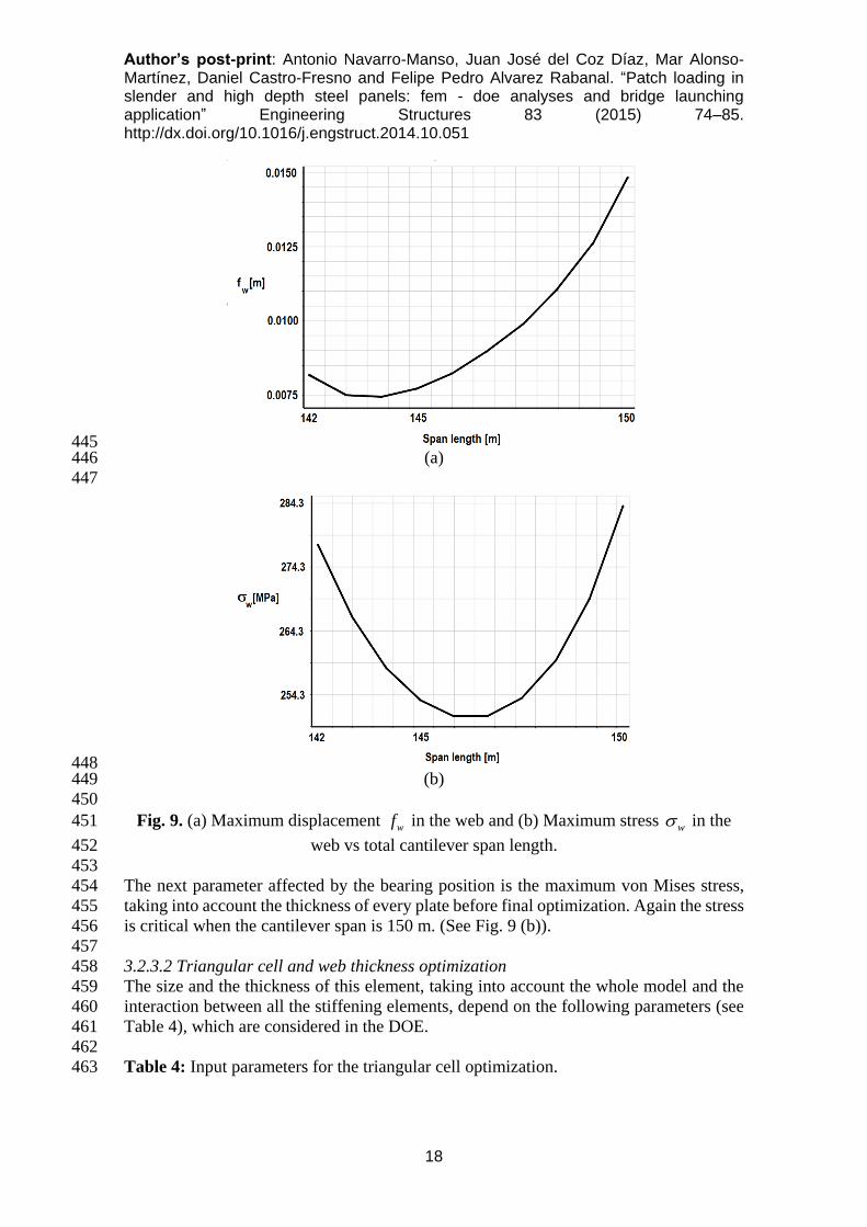
second transversal frame, as can be seen in Fig.9 (a). 443
444
Author’s post-print: Antonio Navarro-Manso, Juan José del Coz Díaz, Mar Alonso-Martínez, Daniel Castro-Fresno and Felipe Pedro Alvarez Rabanal. “Patch loading in slender and high depth steel panels: fem - doe analyses and bridge launching application” Engineering Structures 83 (2015) 74–85. http://dx.doi.org/10.1016/j.engstruct.2014.10.051
18
445 (a) 446
447
448 (b) 449
450
Fig. 9. (a) Maximum displacement wf in the web and (b) Maximum stress
w in the 451
web vs total cantilever span length. 452
453
The next parameter affected by the bearing position is the maximum von Mises stress, 454
taking into account the thickness of every plate before final optimization. Again the stress 455
is critical when the cantilever span is 150 m. (See Fig. 9 (b)). 456
457
3.2.3.2 Triangular cell and web thickness optimization 458
The size and the thickness of this element, taking into account the whole model and the 459
interaction between all the stiffening elements, depend on the following parameters (see 460
Table 4), which are considered in the DOE. 461
462
Table 4: Input parameters for the triangular cell optimization. 463

Author’s post-print: Antonio Navarro-Manso, Juan José del Coz Díaz, Mar Alonso-Martínez, Daniel Castro-Fresno and Felipe Pedro Alvarez Rabanal. “Patch loading in slender and high depth steel panels: fem - doe analyses and bridge launching application” Engineering Structures 83 (2015) 74–85. http://dx.doi.org/10.1016/j.engstruct.2014.10.051
19
Minimum Initial Maximum
Cantilever span L 150 150 150
Depth H [m] 0.2 0.6 0.8
Thickness ec [m] 0.020 0.025 0.035
Web Thickness ew [m] 0.020 0.025 0.035
464
The most relevant parameter is the web thickness, since the maximum load and the width 465
of the launching support were established before. Fig. 10 shows the response surfaces of 466
the main output parameters, web deflection (Fig. 10a) and web stress (Fig. 10b) 467
depending on the height of the triangular cell and the thickness of the web. 468
469
(a)
(b)
Fig. 10. Maximum displacement (a) and maximum stress (b) in the web vs web 470
thickness and cell height. 471
472
A symmetric design of the triangular cell is adopted because the thickness of each plate 473
(inside and outside) is not important enough and possible errors in the assembly of the 474
steel structure are avoided. The results obtained, which comply with both conditions - 475
web deflection and von Mises stress - are summarized in Table 5: 476
477
Table 5: Output results for the triangular cell optimization. 478
Web thickness ew Cell thickness ec Cell height h
[m] 0.030 0.025 0,5
479
480
3.2.4. Final Design, longitudinal stiffener position and depth of the stiffeners results 481
A lot of references can be found in literature that try to define the best position of the 482
longitudinal stiffener with respect to the bottom of a beam made of steel. Some boundary 483
Author’s post-print: Antonio Navarro-Manso, Juan José del Coz Díaz, Mar Alonso-Martínez, Daniel Castro-Fresno and Felipe Pedro Alvarez Rabanal. “Patch loading in slender and high depth steel panels: fem - doe analyses and bridge launching application” Engineering Structures 83 (2015) 74–85. http://dx.doi.org/10.1016/j.engstruct.2014.10.051
20
conditions and loads are also extensively tested. Hence, this study takes the value of 30% 484
web depth as the first step to carry out the DOE. In this case, the location of the 485
longitudinal stiffener is the most important parameter from the web deflection point of 486
view. Once the location is defined, the next most important parameter is the stiffener 487
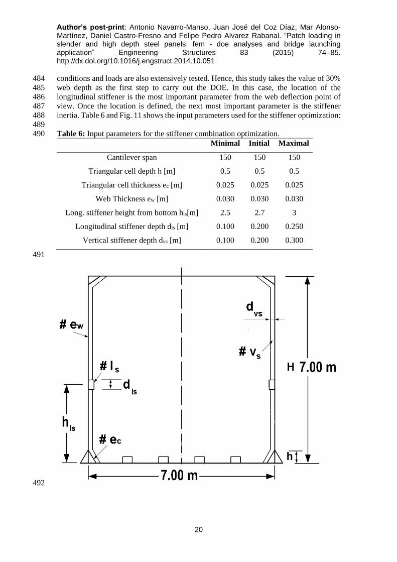
inertia. Table 6 and Fig. 11 shows the input parameters used for the stiffener optimization: 488
489
Table 6: Input parameters for the stiffener combination optimization. 490
Minimal Initial Maximal
Cantilever span 150 150 150
Triangular cell depth h [m] 0.5 0.5 0.5
Triangular cell thickness ec [m] 0.025 0.025 0.025
Web Thickness ew [m] 0.030 0.030 0.030
Long. stiffener height from bottom hls[m] 2.5 2.7 3
Longitudinal stiffener depth dls [m] 0.100 0.200 0.250
Vertical stiffener depth dvs [m] 0.100 0.200 0.300
491
492
Author’s post-print: Antonio Navarro-Manso, Juan José del Coz Díaz, Mar Alonso-Martínez, Daniel Castro-Fresno and Felipe Pedro Alvarez Rabanal. “Patch loading in slender and high depth steel panels: fem - doe analyses and bridge launching application” Engineering Structures 83 (2015) 74–85. http://dx.doi.org/10.1016/j.engstruct.2014.10.051
21
Fig. 11. Input parameters used for the stiffener optimization. 493
494
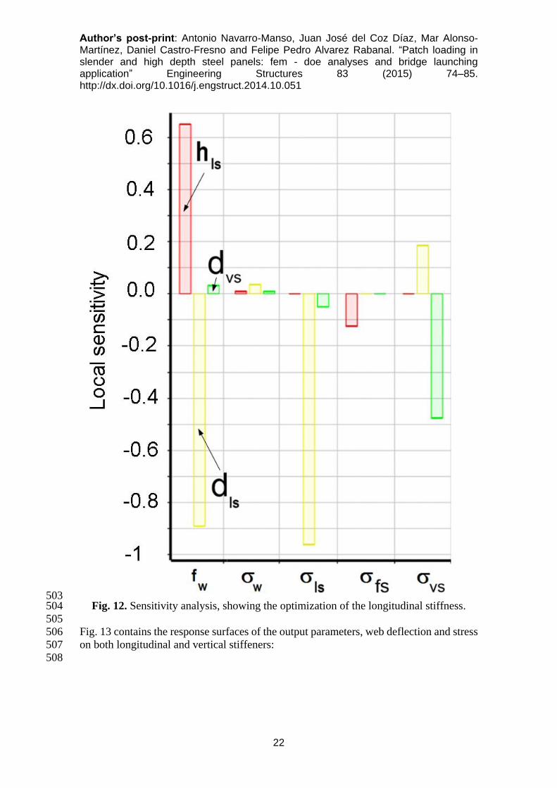
The maximum von Mises stress in the web remains virtually constant. The depth of both 495
longitudinal and vertical stiffeners only control the stress in the elements themselves. As 496
was seen in the previous analysis the stresses are always less than the elastic yield stress 497
of steel. The fact that the whole design is being carried out with the objective of making 498
the stresses lower than 60% of the yield stress of S-355 steel grade must be highlighted. 499
Fig. 12 shows the sensitivity analysis results from the DOE, in which the relative 500
influence of each input parameter on the outputs are shown: 501
502
Author’s post-print: Antonio Navarro-Manso, Juan José del Coz Díaz, Mar Alonso-Martínez, Daniel Castro-Fresno and Felipe Pedro Alvarez Rabanal. “Patch loading in slender and high depth steel panels: fem - doe analyses and bridge launching application” Engineering Structures 83 (2015) 74–85. http://dx.doi.org/10.1016/j.engstruct.2014.10.051
22
503 Fig. 12. Sensitivity analysis, showing the optimization of the longitudinal stiffness. 504
505
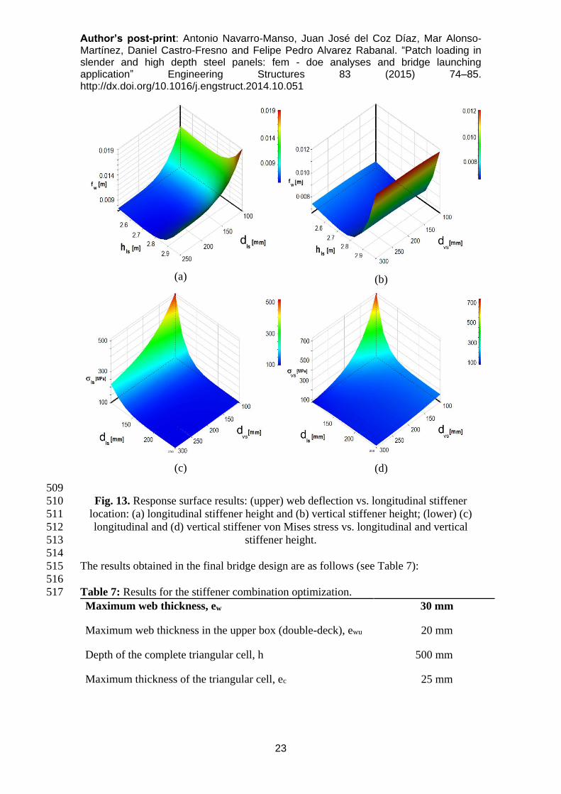
Fig. 13 contains the response surfaces of the output parameters, web deflection and stress 506
on both longitudinal and vertical stiffeners: 507
508
Author’s post-print: Antonio Navarro-Manso, Juan José del Coz Díaz, Mar Alonso-Martínez, Daniel Castro-Fresno and Felipe Pedro Alvarez Rabanal. “Patch loading in slender and high depth steel panels: fem - doe analyses and bridge launching application” Engineering Structures 83 (2015) 74–85. http://dx.doi.org/10.1016/j.engstruct.2014.10.051
23
(a)
(b)
(c)
(d)
509
Fig. 13. Response surface results: (upper) web deflection vs. longitudinal stiffener 510
location: (a) longitudinal stiffener height and (b) vertical stiffener height; (lower) (c) 511
longitudinal and (d) vertical stiffener von Mises stress vs. longitudinal and vertical 512
stiffener height. 513
514
The results obtained in the final bridge design are as follows (see Table 7): 515
516
Table 7: Results for the stiffener combination optimization. 517
Maximum web thickness, ew 30 mm
Maximum web thickness in the upper box (double-deck), ewu 20 mm
Depth of the complete triangular cell, h 500 mm
Maximum thickness of the triangular cell, ec 25 mm
Author’s post-print: Antonio Navarro-Manso, Juan José del Coz Díaz, Mar Alonso-Martínez, Daniel Castro-Fresno and Felipe Pedro Alvarez Rabanal. “Patch loading in slender and high depth steel panels: fem - doe analyses and bridge launching application” Engineering Structures 83 (2015) 74–85. http://dx.doi.org/10.1016/j.engstruct.2014.10.051
24
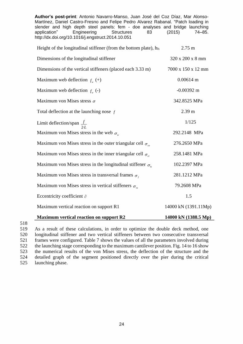
Height of the longitudinal stiffener (from the bottom plate), hls 2.75 m
Dimensions of the longitudinal stiffener 320 x 200 x 8 mm
Dimensions of the vertical stiffeners (placed each 3.33 m) 7000 x 150 x 12 mm
Maximum web deflection wf (+) 0.00614 m
Maximum web deflection wf (-) -0.00392 m
Maximum von Mises stress 342.8525 MPa
Total deflection at the launching nose f 2.39 m
Limit deflection/span 2·
f
L 1/125
Maximum von Mises stress in the web w 292.2148 MPa
Maximum von Mises stress in the outer triangular cell co 276.2650 MPa
Maximum von Mises stress in the inner triangular cell ci 258.1481 MPa
Maximum von Mises stress in the longitudinal stiffener ls 102.2397 MPa
Maximum von Mises stress in transversal frames f 281.1212 MPa
Maximum von Mises stress in vertical stiffeners vs 79.2608 MPa
Eccentricity coefficient 1.5
Maximum vertical reaction on support R1 14000 kN (1391.11Mp)
Maximum vertical reaction on support R2 14000 kN (1388.5 Mp)
518
As a result of these calculations, in order to optimize the double deck method, one 519
longitudinal stiffener and two vertical stiffeners between two consecutive transversal 520
frames were configured. Table 7 shows the values of all the parameters involved during 521
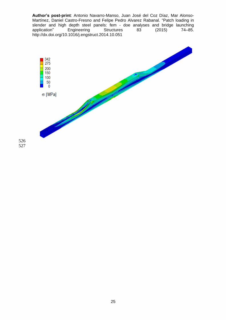
the launching stage corresponding to the maximum cantilever position. Fig. 14 to 16 show 522
the numerical results of the von Mises stress, the deflection of the structure and the 523
detailed graph of the segment positioned directly over the pier during the critical 524
launching phase. 525
Author’s post-print: Antonio Navarro-Manso, Juan José del Coz Díaz, Mar Alonso-Martínez, Daniel Castro-Fresno and Felipe Pedro Alvarez Rabanal. “Patch loading in slender and high depth steel panels: fem - doe analyses and bridge launching application” Engineering Structures 83 (2015) 74–85. http://dx.doi.org/10.1016/j.engstruct.2014.10.051
25
526 527

Author’s post-print: Antonio Navarro-Manso, Juan José del Coz Díaz, Mar Alonso-Martínez, Daniel Castro-Fresno and Felipe Pedro Alvarez Rabanal. “Patch loading in slender and high depth steel panels: fem - doe analyses and bridge launching application” Engineering Structures 83 (2015) 74–85. http://dx.doi.org/10.1016/j.engstruct.2014.10.051
26
528 529
Fig. 14. Optimized von Mises stress, during the critical launching phase: overall view 530
(upper) and segment directly over the pier (lower). 531
532
533 Fig. 15. Deflection, during the critical launching phase, 150 m cantilever span. 534
535
Author’s post-print: Antonio Navarro-Manso, Juan José del Coz Díaz, Mar Alonso-Martínez, Daniel Castro-Fresno and Felipe Pedro Alvarez Rabanal. “Patch loading in slender and high depth steel panels: fem - doe analyses and bridge launching application” Engineering Structures 83 (2015) 74–85. http://dx.doi.org/10.1016/j.engstruct.2014.10.051
27
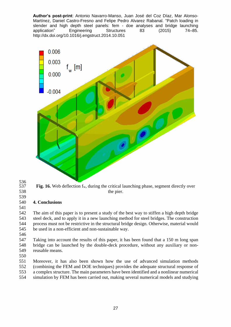
536 Fig. 16. Web deflection fw, during the critical launching phase, segment directly over 537
the pier. 538
539
4. Conclusions 540
541
The aim of this paper is to present a study of the best way to stiffen a high depth bridge 542
steel deck, and to apply it in a new launching method for steel bridges. The construction 543
process must not be restrictive in the structural bridge design. Otherwise, material would 544
be used in a non-efficient and non-sustainable way. 545
546
Taking into account the results of this paper, it has been found that a 150 m long span 547
bridge can be launched by the double-deck procedure, without any auxiliary or non-548
reusable means. 549
550
Moreover, it has also been shown how the use of advanced simulation methods 551
(combining the FEM and DOE techniques) provides the adequate structural response of 552
a complex structure. The main parameters have been identified and a nonlinear numerical 553
simulation by FEM has been carried out, making several numerical models and studying 554
Author’s post-print: Antonio Navarro-Manso, Juan José del Coz Díaz, Mar Alonso-Martínez, Daniel Castro-Fresno and Felipe Pedro Alvarez Rabanal. “Patch loading in slender and high depth steel panels: fem - doe analyses and bridge launching application” Engineering Structures 83 (2015) 74–85. http://dx.doi.org/10.1016/j.engstruct.2014.10.051
28
them within a wide range of cases. The most important variables were then optimized by 555
means of sensitivity analysis and design of experiments (DOE). 556
557
The principal conclusions are the following: 558
559
- The triangular cell along the down flange (both inside and outside the web) is a 560
very important stiffener that contributes to patch loading resistance. Web stress is 561
decreased by about 30% when 20∙10-3 m thick plates are used. 562
- Many authors have proposed a maximum web height of 4 m to use the transversal 563
stiffeners instead of longitudinal stiffeners. Nevertheless the optimum stiffener 564
distribution consists of a combination of both longitudinal and transversal, called 565
CASE-VI. There are two longitudinal stiffeners, one of them is the triangular cell 566
and the other is located approximately at 3
h from the deck bottom. The transversal 567
stiffeners are vertical profiles, located between the transversal frames of the deck. 568
- Web deflection, one of the most important design parameters, mostly depends on 569
the web thickness and the location of the second longitudinal stiffener. 570
- Web tensional states are controlled by the triangular cell along the down plate of 571
the deck. Patch loading resistance is defined by this strong longitudinal stiffener 572
which allows optimization of the web thickness along the whole deck. 573
574
The results then lead us to future investigations in many fields. After the analysis of a 575
new launching method in this paper, the objective will be to analyze the effect of the real 576
deflection of the steel beam in the reaction forces on both the piers and the pushing 577
mechanism. 578
579
The authors suggest a future research line about the development of testing on prototype 580
models of the bridge launched (e.g. scale 1:15) in order to calibrate more accurately the 581
numerical simulations. 582
583
A high level of development along these research lines is current expected in order to 584
regulate and integrate the different international codes regarding buckling formulation 585
and bridge construction systems. 586
587
5. Acknowledgements 588
The authors of this paper greatly appreciate the collaboration of the GICONSIME 589
Research Group at the University of Oviedo, the GITECO Research Group at the 590
University of Cantabria, The Polytechnic University of Madrid, COPROSA Ltd, ULMA 591
Ltd. and Torroja Ltd. and, specifically, to Víctor Orodea López, Javier Merino Rasines, 592
Benjamín Navamuel García; José Simón Talero and Maximino Menéndez Cabo. 593
Furthermore, the authors wish to acknowledge the financial support provided by the 594
Spanish Ministry of Science and Innovation with funds from ALCANZA Research 595
Project number IPT-380000-2010-12 and BIA-2012-31609. These projects have been co-596
Author’s post-print: Antonio Navarro-Manso, Juan José del Coz Díaz, Mar Alonso-Martínez, Daniel Castro-Fresno and Felipe Pedro Alvarez Rabanal. “Patch loading in slender and high depth steel panels: fem - doe analyses and bridge launching application” Engineering Structures 83 (2015) 74–85. http://dx.doi.org/10.1016/j.engstruct.2014.10.051
29
financed with FEDER funds, “A Way of Making Europe”. Besides, we also thank 597
Swanson Analysis Inc. for the use of the ANSYS University Research program and 598
Workbench simulation environment. Finally, the authors wish to acknowledge the 599
English editing work made by Andrew McCammond. 600
601
6. References 602
603
[1]. Bernabeu Larena J. Typology and Aesthetic Evolution of the European Composite 604
Bridges. Doctoral Thesis. Madrid UPM Department of Structural Engineering; 605
Spain. 2004. 606
[2]. German Patent DE1237603 (B). Verfahren zum herstellen von langen 607
bauwerken,insbesondere bruecken, aus stahl-oder spannbeton. 1967. 608
[3]. Rosignoli M. Bridge launching. London. Thomas Telford. 2002. 609
[4]. Navarro-Manso A. A new steel bridge launching system based on self-supporting 610
double deck: structural numerical simulation and wind tunnel tests. Doctoral Thesis. 611
University of Cantabria; Spain 2013. 612
[5]. Bouchon E. et al. Guide des ponts poussés. Presses de l´ecole nationale des ponts et 613
chaussees. Paris. 1999. 614
[6]. Petetin S. et al. Bulletin 23 Ponts Metalliques 2004. OUTA. Paris. 2004. 615
[7]. La Violette M. et al. Bridge construction practices using incremental launching. 616
AASHTO. Washington. D. C. 2007. 617
[8]. Alonso-Martínez M. New device for continuous launching of bridge structures: 618
design and analysis using numerical simulation. Doctoral Thesis. University of 619
Oviedo. Spain. 2013. 620
[9]. De Matteis D. et al. Steel-Concrete Composite Bridges, Sustainable Design Guide. 621
SETRA Ministere de l´Ecologie, de l´Energie, du Developpement durable et de la 622
Mer. France. 2010. 623
[10]. Kuhlmann U. et al. COMBRI Design Manual. Part II: State-of-the-Art and 624
Conceptual Design of Steel and Composite Bridges. Research Fund for Coal and 625
Steel and University of Stuttgart. Institute of Structural Design. European 626
Commission. 2008. 627
[11]. International Patent WO 2013/001115 A1. System and method for launching 628
structures. 2012. 629
[12]. International Patent WO 2013/001114 A1. Device to continuous displacement of 630
structures. 2012. 631
[13]. Lagerqvist O. Patch loading: resistance of steel girders subjected to concentrated 632
forces. Doctoral thesis. Lulea University. Sweden. 1994. 633
[14]. Granath P. Serviceability limit state of I-shaped steel girders subjected to patch 634
loading. J Const Steel Res 2000; 54(3): 387-408. 635
[15]. Graciano C, Edlund B. Failure mechanism of slender girder webs with a 636
longitudinal stiffener under patch loading. J Const Steel Res 2003;59(1):27–45. 637
[16]. Hajdin N, Markovic N. Failure mechanism for longitudinally stiffened I girders 638
subjected to patch loading. Archive of Applied Mechanics 2012;82:1377–91. 639
[17]. Marchetti M.E. Specific design problems related to bridges built using the 640
incremental launching method. Eng Struct 1984; 6: 185-210. 641
Author’s post-print: Antonio Navarro-Manso, Juan José del Coz Díaz, Mar Alonso-Martínez, Daniel Castro-Fresno and Felipe Pedro Alvarez Rabanal. “Patch loading in slender and high depth steel panels: fem - doe analyses and bridge launching application” Engineering Structures 83 (2015) 74–85. http://dx.doi.org/10.1016/j.engstruct.2014.10.051
30
[18]. Graciano C. Patch loading: Resistance of longitudinally stiffened steel girder 642
webs. Doctoral thesis. Lulea University of Technology. Sweeden. 2001. 643
[19]. Navarro–Manso A., Del Coz Diaz J.J., Alonso Martinez M., Castro-Fresno D., 644
Blanco-Fernández E. New launching method for steel bridges based on a self-645
supporting deck system: FEM and DOE analysis. Autom Constr 2014; 44: 183-196. 646
[20]. Alonso-Martinez M., del Coz Díaz J.J., Navarro-Manso A., Castro-Fresno D. 647
Bridge–structure interaction analysis of a new bidirectional and continuous 648
launching bridge mechanism. Eng Struct 2014; 59: 298-307. 649
[21]. Alonso-Martínez M., del Coz Díaz J.J., Castro-Fresno D., Navarro-Manso A. New 650
mechanism for continuous and bidirectional displacement of heavy structures: 651
Design and analysis. Autom Constr 2014; 44: 47-55. 652
[22]. ANSYS, Inc, ANSYS Release 12.0 Elements Reference, USA; 2009. 653
[23]. Graciano C, Edlund B. Nonlinear FE analysis of longitudinally stiffened girder 654
webs under patch loading. J Const Steel Res 2002;8:1231–1245. 655
[24]. Millanes Mato F., Pascual Santos J., Ortega Cornejo M. Arroyo las Piedras 656
viaduct: The first Composite Steel-Concrete High Speed Railway Bridge in Spain. 657
Hormigón y Acero 2007; 243: 5-38. 658
[25]. ASME BPVC-Rules for Construction of Pressure Vessels Division 2-Alternative 659
Rules. ASME. USA. 2013. 660
[26]. UNE - EN 1993-1-5. Design of steel structures. Part 1-5: Plated structural 661
elements. AENOR. Madrid. 2008. 662
[27]. Gozzi J. Patch loading: Resistance of plated girders. Ultimate and serviceability 663
limit state. Doctoral thesis. Lulea University of Technology Sweeden. 2007. 664
[28]. Chacon R., Mirambell E., Real E. Influence of designer-assumed initial conditions 665
on the numerical modelling of steel plate girders subjected to patch loading. Thin-666
Walled Struct 2009; 47(4): 391-402. 667
[29]. del Coz Díaz J.J., Álvarez Rabanal F.P., García Nieto P.J., Roces-García J., 668
Alonso-Estébanez A. Nonlinear buckling and failure analysis of a self-weighted 669
metallic roof with and without skylights by FEM. Eng Fail Anal 2012; 26: 65-80. 670
[30]. del Coz Díaz J.J., Serrano López M.A., López-Colina Pérez C., Álvarez Rabanal 671
F.P. Effect of the vent hole geometry and welding on the static strength of galvanized 672
RHS K-joints by FEM and DOE. Eng Struct 2012; 41: 218-233. 673
[31]. Box G, Hunter W, Hunter J. Statistics for experimenters. Second Ed. Wiley, 2005. 674
[32]. D.C. Montgomery, Design and Analysis of Engineering Experiments, 5th ed., 675
John Wiley & Sons, New York, 2001. 676
[33]. R.H. Myers, D.C. Montgomery, Response Surface Methodology: Process and 677
Product Optimization Using Designed Experiments, 2nd ed., John Wiley & Sons, 678
New York, 2002. 679

![INTERVENTIONS - University of Minnesota · Felipe II’s imperial regimes. Pettinaroli theorizes “that Alonso de Santa Cruz’s dramatic description emplaces the [Magdalena] river](https://img.pdfslide.us/doc/110x75/5e9e94688a75772b9904175d/interventions-university-of-minnesota-felipe-iias-imperial-regimes-pettinaroli.jpg)