Embed Size (px)
Citation preview

R
Safety Switches
Tongue Switches
3-14
Cadet™ 3
Visit our website: www.ab.com/catalog
Publication S117-CA001A-EN-P
General
1-2-O
pto
-electronics
3-Interlock
Sw
itchesO
perato
rInterface
Log
icP
ow
er
Description
Features
Specifications
� Compact size� Ideal for small, lightweight guards� Contacts, 2 N.C. and 1 N.O. or 3 N.C. � Sealed to IP67� Eight possible actuator entry points, easy to install� Industry standard fixing centres to DIN 50047� GD2 style available for demanding applications
Safety Ratings
StandardsEN954-1, ISO13849-1, IEC/EN60204-1,NFPA79, EN1088, ISO14119, IEC/EN60947-5-1, ANSI B11.19, AS4024.1
Safety ClassificationCat. 1 device per EN 954-1 dualchannel interlocks suitable for Cat. 3 or4 systems
Certifications CE Marked for all applicable directives,cULus, TÜV, and CCC
Outputs
Safety Contacts �Direct Opening Action
2 N.C. 3 N.C.
Auxiliary Contacts 1 N.O. None
Thermal CurrentIlth 10 A
Rated Insulation Voltage (Ui) 500V
Switching Current @ Voltage, Min. 5 mA @ 5V DC
Utilization Category
A600/AC-15 (Ue) 600V 500V 240V 120V
(le) 1.2 A 1.4 A 3.0 A 6.0 A
DC-13 (Ue) 24V
(le) 2 A
Operating Characteristics
Break Contact Force, Min. 15 N (3.37 lbf)
Actuation Speed, Max. 160 mm (6.29 in.)/s
Actuation Frequency, Max. 2 cycles/s
Operating Radius, Min 150 mm (5.90 in.) [60 mm (2.36 in.) withGD2 kit]
Operating Life @ 100 mA load 1 x 10⁶ operations
Environmental
Enclosure Type Rating IP67
Operating Temperature [C (F)] -20…+ 80° (-4…+176°)
Physical Characteristics
Housing Material UL Approved glass-filled PBT
Actuator Material Stainless Steel
Weight [g (lb)] 80 (0.176)
Color Red
� Usable for ISO 13849-1:2006 and IEC 62061. Data other than B10d isbased on:- Usage rate of 1op/10 mins., 24 hrs/day, 360 days/year, representing
51840 operations per year- Mission time/Proof test interval of 38 years
� The safety contacts are described as normally closed (N.C.) i.e., with theguard closed, actuator in place (where relevant) and the machine able to bestarted.
The Cadet 3 is a tongue-operated (or key-operated) safety interlockswitch designed to fit at the leading edge of sliding, hinged or lift-offguards. With its dual entry slots and rotatable head, the versatileCadet 3 can offer up to eight different actuator entry options. Theunique compact housing (90.5 x 31 x 30.4 mm (3.56 x 1.22 x1.19 in.)) has industry standard DIN 50047 fixing centers for ease ofmounting.
Operation of the switch is achieved through the insertion of aspecially-profiled stainless-steel key that is permanently mounted tothe guard door. A semi-flexible key allows the Cadet 3 to be usedon small-radii doors (60 mm or 2.36 in.).
Available with a variety of contact configurations, the Cadet 3 issealed to IP67. A blanking plug is supplied for the unused key entry.
03-SafetySw_1_Tongue:03-SafetySw1 Tng.qxd 5/6/2010 10:53 AM Page 3-14
AUDIN - 8, avenue de la malle - 51370 Saint Brice Courcelles - Tel : 03.26.04.20.21 - Fax : 03.26.04.28.20 - Web : http: www.audin.fr - Email : [email protected]

R
Safety Switches
Tongue Switches
3-15
Cadet™ 3
Visit our website: www.ab.com/catalogs
Publication S117-CA001A-EN-P
Gen
eral
1-2-
Op
to-e
lect
roni
cs3-
Inte
rlo
ckS
witc
hes
Op
erat
or
Inte
rfac
eLo
gic
Po
wer
Product Selection
Recommended Logic Interfaces
Connection Systems
Description6-Pin Micro
(M12)5-Pin Micro
(M12)
Cordset 889R-F6ECA-� —
Patchcord 889R-F6ECRM-� 889R-F5ECRM-�
Distribution Box 898R-P68MT-A5 —
Shorting Plug 898R-P61MU-RM —
T-Port NA —
Contact
Actuator Type
Cat. No.
Safety Auxiliary Action
M16 Conduit Connector§
M161/2 inch NPT
Adaptor
Connect toDistribution
Box6-Pin Micro
(M12)
Connect toArmorBlock Guard
I/O5-Pin Micro
(M12)♣
3 N.C. — —
Flat 440K-C21096 440K-C21048 440K-C21090 440K-C2NNFPS
90° 440K-C21097 440K-C21057 440K-C21091 ⎯GD2 Metal alignment guide
w/semi-flex actuator ⎯ 440K-C21062 440K-C21092 440K-C2NNAPS
— 440K-C21070 ⎯ ⎯ ⎯
2 N.C. 1 N.O.
BBM
Flat 440K-C21098 440K-C21050 440K-C21054 ⎯90° 440K-C21061 440K-C21058 440K-C21067 ⎯
GD2 Metal alignment guidew/semi-flex actuator ⎯ 440K-C21074 440K-C21088 ⎯
— 440K-C21055 ⎯ ⎯ ⎯
MBB
Flat 440K-C21052 440K-C21093 440K-C21060 ⎯90° 440K-C21065 440K-C21094 440K-C21068 ⎯
GD2 Metal alignment guidew/semi-flex actuator ⎯ 440K-C21095 440K-C21089 ⎯
— 440K-C21080 ⎯ ⎯ ⎯
§ For connector ratings see page 3-9.§ With a 5-pin micro (M12) connector, not all contacts are connected. See Typical Wiring Diagram on page 3-17 for wiring details.
Description Safety Outputs Auxiliary Outputs Terminals Reset Type Power Supply Cat. Page No. Cat. No.
Single-Function Safety Relays
MSR127RP 3 N.O. 1 N.C. Removable (Screw) Monitored Manual 24V AC/DC 5-24 440R-N23135
MSR127TP 3 N.O. 1 N.C. Removable (Screw) Auto./Manual 24V AC/DC 5-24 440R-N23132
MSR126T 2 N.O. None Fixed Auto./Manual 24V AC/DC 5-22 440R-N23117
MSR30RT 2 N.O. Solid State 1 N.O. Solid State Removable Auto./Manual orMonitored Manual 24V DC 5-16 440R-N23198
Modular Safety Relays
MSR210P Base2 N.C. only 2 N.O. 1 N.C. and 2 PNP
Solid State Removable Auto./Manual orMonitored Manual
24V DC from thebase unit 5-74 440R-H23176
MSR220P InputModule — — Removable — 24V DC 5-78 440R-H23178
MSR310P Base MSR300 SeriesOutput Modules 3 PNP Solid State Removable Auto./Manual
Monitored Manual 24V DC 5-94 440R-W23219
MSR320P InputModule — 2 PNP Solid State Removable — 24V DC from the
base unit 5-98 440R-W23218
Note: For additional Safety Relays connectivity, see the Safety Relays section (page 5-8) of this catalog.For additional Safety I/O and Safety PLC connectivity, see the Programmable Safety System section (page 5-107) of this catalog.For application and wiring diagrams, see the Safety Applications section (page 10-1) of this catalog.
� Replace symbol with 2 (2 m), 5 (5 m), or 10 (10 m) for standard cable lengths.�Replace symbol with 1 (1 m), 2 (2 m), 3 (3 m), 5 (5 m), or 10 (10 m) for standard cable lengths.Note: For additional information, see the Safety Connection System section (page 7-1) of this catalog.
03-SafetySw_1_Tongue:03-SafetySw1 Tng.qxd 5/6/2010 10:53 AM Page 3-15
AUDIN - 8, avenue de la malle - 51370 Saint Brice Courcelles - Tel : 03.26.04.20.21 - Fax : 03.26.04.28.20 - Web : http: www.audin.fr - Email : [email protected]

R
Safety Switches
Tongue Switches
3-16
Cadet™ 3
Visit our website: www.ab.com/catalog
Publication S117-CA001A-EN-P
General
1-2-O
pto
-electronics
3-Interlock
Sw
itchesO
perato
rInterface
Log
icP
ow
er
M16Thread Form
31.0 (1.22)
34.4 (1.35)
38.4 (1.51)90.5 (3.56)
R 2.15
Front Entry
4 (0.16)
4.5 (0.18)
25.0
(0.
98)
30.4
(1.
2)4.5 (0.18)
4 (0.16)
13.
0 (0
.51
)
20.
0 (0
.79
)
22.
0 (0
.87
)
25.
0 (0
.98
)
13.0 (0.51)
13.0 (0.51)
36.4 (1.43)
Accessories
Note: 2D, 3D and electrical drawings are available on www.ab.com.
Dimensions are shown in mm (in.). Dimensions are not intended to be used for installation purposes.
Approximate Dimensions
Description Dimensions Cat. No.
Flat actuator, not to be used with metalalignment guide
3-52
440K-A21014
90° actuator, not to be used with metalalignment guide 440K-A21006
Metal alignment guide with semi-flexible actuator 440K-A21030
Replacement Cover — 440A-A21115
Dust Cover — 440K-A17182
03-SafetySw_1_Tongue:03-SafetySw1 Tng.qxd 5/6/2010 10:53 AM Page 3-16
AUDIN - 8, avenue de la malle - 51370 Saint Brice Courcelles - Tel : 03.26.04.20.21 - Fax : 03.26.04.28.20 - Web : http: www.audin.fr - Email : [email protected]

R
Safety Switches
Tongue Switches
3-17
Cadet™ 3
Visit our website: www.ab.com/catalogs
Publication S117-CA001A-EN-P
Gen
eral
1-2-
Op
to-e
lect
roni
cs3-
Inte
rlo
ckS
witc
hes
Op
erat
or
Inte
rfac
eLo
gic
Po
wer
Typical Wiring Diagrams
Description 2 N.C. & 1 N.O. 3 N.C.
Contact Configuration
33 34
21 22
11 12 Safety A (NC)
Safety B (NC)
Aux A (NO)
21 22
11 12 Safety A (NC)
Safety B (NC)
Safety C (NC)31 32
Contact Action
3.1
3.7
Safety ASafety B
Aux A
0 mm
BBM3.1 0 mm
Safety ASafety B
Aux A
Open Closed
3.5
2.5
Safety ASafety BSafety C
0 mm
MBB
6-Pin Micro (M12)
5-Safety A
6-Safety B
1-Safety A
4-Aux A
3-Aux A2-Safety B
5-Safety A
6-Safety B
1-Safety A
4-Safety C
3-Safety C2-Safety B
5-Pin Micro (M12) —
5-Safety B
4-Safety B3-N/A
1-Safety A
2-Safety A
Cordset889R-F6ECA-�
Red/WhiteSafety A Safety A
Red/Black
RedSafety B Safety B
Red/Blue
GreenAux A Safety C
Red/Yellow
� Replace symbol with 2 (2 m), 5 (5 m) or 10 (10 m) for standard cable lengths.
03-SafetySw_1_Tongue:03-SafetySw1 Tng.qxd 5/6/2010 10:53 AM Page 3-17
AUDIN - 8, avenue de la malle - 51370 Saint Brice Courcelles - Tel : 03.26.04.20.21 - Fax : 03.26.04.28.20 - Web : http: www.audin.fr - Email : [email protected]

Safety Switches
Accessories
3-50Visit our website: www.ab.com/catalog
Publication S117-CA001A-EN-P
Actuators
General
1-2-O
pto
-electronics
3-Interlock
Sw
itchesO
perato
rInterface
Log
icP
ow
er
R
Accessories for Interlock and Guard Locking Switches
Item Description Approximate Dimensions [mm (in.)] Cat. No.
Standard actuator
10.5
(0.
41)
3.5 (0.14)
56 (
2.2)
5 (0.2)
5 (0.2)
18 (0.71)
4 (0
.16)
30 (1.18)
50 (1.97) 2 x M5
10 (0.39)
440G-A07136
Fully flex actuator
90 (3.54)
M5
77 (3.03)
M5
75 (
2.95
)
10 (
0.39
)
24 (
0.94
)
9 (0
.35)18
(0.
7)
21 (
0.82
)
440G-A07269
GD2 standard actuator
18
(0.71)
36 (
1.42
)
4 (0
.16)
3.5 (0.14)
40 (1.57)
52 (2.05)
14.5
(0.5
7)
M5 CSK
440G-A27011
Fully flex actuator
31 (
1.22
40 (
1.57
)
52 (
2.05
)
8 (0.31)
6.8 (0.27)
20(0.79)
13 (
0.51
)19
(0.
75)
4 x Ø5.5(0.22)
2 x M3
51(2
.01)
18(0.71)
Adjustingscrews
440G-A27143
Catch and Retainer Kit 52 (2.05)
11.2
(0.4
4)
29 (
1.14
)
52 (20.5)
7.25
(0.2
9)
40 (1.57)
14.5
(0.5
7)25
.5
(1.0
)
1.5
(0.0
6)
18
(0.71)
4
(0.16)440K-A11094
Actuators�
� See page 3-8 for Switch Compatibility table.
03-SafetySw_2_GuardLock 5/3/2010 2:20 PM Page 3-50
AUDIN - 8, avenue de la malle - 51370 Saint Brice Courcelles - Tel : 03.26.04.20.21 - Fax : 03.26.04.28.20 - Web : http: www.audin.fr - Email : [email protected]

Safety Switches
Accessories
3-51Visit our website: www.ab.com/catalogs
Publication S117-CA001A-EN-P
Actuators
Gen
eral
1-2-
Op
to-e
lect
roni
cs3-
Inte
rlo
ckS
witc
hes
Op
erat
or
Inte
rfac
eLo
gic
Po
wer
R
Actuators� (continued)
Item Description Approximate Dimensions [mm (in.)] Cat. No.
Standard actuator
M5 CSK40 (1.57)
52 (2.05)
5 (0
.2)
31.2
(1.
23)
17.5
(0.69)
3.5
(0.14)
14.5
(0.57)
440K-A11095
GD2 flat actuator
17.5
(0.69)
36 (1.42)
25(0
.98)
57 (
2.24
)
3.5
(0.14)
440K-A11112
Replacement AlignmentGuide 52 (2.05)
35 (
1.38
)29
(1.
14)
20.7 (0.81)
32.7 (1.29)
20.7 (0.81)
32.7 (1.29) 440K-A11115
Alignment guide withsemi-flexible actuator
35 29
15.5(0.61)
14(0.55)
46.5
(1.
83)
8.5(0.33)
14 (0.55)
52.0(2.04)
20.7(0.81) 32.7
(1.29) 55.5 (2.19)
40 (1.57)
440K-A11144
Standard actuator
M5 CSK40 (1.57)
52 (2.05)
5 (0
.2)
31.2
(1.
23)
17.5
(0.69)
3.5
(0.14)
14.5
(0.57)
440K-A11238
Extended flat actuator
17.5
(0.69)
70 (
2.75
)
20(0
.78)
7 (0
.27)
32.2
(1.
26)
3 (0
.11)
10.8
(0.
42)
8 (0
.31)
15 (0.59)
Ø5.2 (Ø0.2)
36 (1.41)
440K-A17116
� See page 3-8 for Switch Compatibility table.
03-SafetySw_2_GuardLock 5/3/2010 2:20 PM Page 3-51
AUDIN - 8, avenue de la malle - 51370 Saint Brice Courcelles - Tel : 03.26.04.20.21 - Fax : 03.26.04.28.20 - Web : http: www.audin.fr - Email : [email protected]

Safety Switches
Accessories
3-52Visit our website: www.ab.com/catalog
Publication S117-CA001A-EN-P
Actuators
General
1-2-O
pto
-electronics
3-Interlock
Sw
itchesO
perato
rInterface
Log
icP
ow
er
R
Actuators� (continued)
Item Description Approximate Dimensions [mm (in.)] Cat. No.
90° actuator, not to beused with metalalignment guide
8.75 (0.34)
18.25 (0.72)
M4
23 (0.91)
1 (0.04)
3 (0.12)
29 (
1.14
)
8 (0
.31)
3 (0
.12)
7.5 (0.3)
24 (0.94)
12(0.47)
440K-A21006
Flat actuator, not to beused with metalalignment guide
12 (0.47)
M4
25 (0.98)
15 (0.59)
3 (0.12)
440K-A21014
Metal alignment guidewith semi-flexible
actuator
12 (0.47)
55.5 (2.19)
15.5
(0.
61)
14 (
0.55
)
40 (
1.57
)
8.5
(0.3
3)
40 (1.57)
440K-A21030
Metal Alignment Guide
19 (0.75)
13.5 (0.53)
3 (0.12)
6 (0.24)
13 (0.51)
25 (0.98)
440K-A21069
Alignment guide withfully-flexible actuator
31 (1.22)
40 (1.57)
52 (2.05)
8 (0
.31)
6.8
(0.2
7)
20 (
0.79
)
13 (
0.51
)
19 (
).75
)
4 x Ø5.5 (Ø0.22)
2 x M3
51 (
2.0)
18
(0.71)
440K-A27010
� See page 3-8 for Switch Compatibility table.
03-SafetySw_2_GuardLock 5/3/2010 2:20 PM Page 3-52
AUDIN - 8, avenue de la malle - 51370 Saint Brice Courcelles - Tel : 03.26.04.20.21 - Fax : 03.26.04.28.20 - Web : http: www.audin.fr - Email : [email protected]

Safety Switches
Accessories
3-53Visit our website: www.ab.com/catalogs
Publication S117-CA001A-EN-P
Beacons, Bulbs and Conduits
Gen
eral
1-2-
Op
to-e
lect
roni
cs3-
Inte
rlo
ckS
witc
hes
Op
erat
or
Inte
rfac
eLo
gic
Po
wer
R
Beacons and Bulbs
Item Description Cat. No.
Indicator, M20 Conduit Pilot Light—Amber Lens T-3 1/4 Insert Use T-3 1/4 Bulb(Sold Separately) 440A-A19001
Indicator, M20 Conduit Pilot Light—Red Lens T-3 1/4 Insert Use T-3 1/4 Bulb(Sold Separately) 440A-A19002
Indicator, 1/2 inch NPT Conduit Pilot Light—Amber Lens T-3 1/4 Insert Use T-3 1/4 Bulb(Sold Separately) 440A-A19005
Indicator, 1/2 inch NPT Conduit Pilot Light—Red Lens T-3 1/4 Insert Use T-3 1/4 Bulb(Sold Separately) 440A-A19007
Bulb, 24V for Conduit Pilot Light 2.8W T-3 1/4 Bulb, Miniature Screw Base 440A-A09056
Bulb, 110V for Conduit Pilot Light 2.6W T-3 1/4 Bulb, Miniature Screw Base 440A-A09055
Bulb, 240V for Conduit Pilot Light 0.75W T-3 1/4 Bulb, Miniature Screw Base 440A-A09054
Red LED Bulb, 24V AC/DC for Conduit Pilot LightBayonet Style Insert 800T-N319R
Amber LED Bulb, 24V AC/DC for Conduit Pilot LightBayonet Style Insert 800T-N319A
Red LED Bulb, 120V AC for Conduit Pilot LightBayonet Style Insert 800T-N320R
Amber LED Bulb, 120V AC for Conduit Pilot LightBayonet Style Insert 800T-N320A
Conduit Accessories
Item Description Cat. No.
Blanking plug, M20 conduit 440A-A07265
Cable Grip, M16 Conduit, Accommodates Cable Diameter 4…7 mm (0.27…0.16 in.) 440A-A09004
Cable grip, M20 conduit, accommodates cable diameter 7…10.5 mm (0.27…0.41 in.) 440A-A09028
Adaptor, conduit, M20 to 1/2 inch NPT, plastic 440A-A09042
Adaptor, Conduit, 1/2 inch NPT to M16, Brass 440A-A09093
Adaptor, Conduit, M16 to 1/2 inch NPT, Brass 440A-A09094
03-SafetySw_2_GuardLock 5/3/2010 2:20 PM Page 3-53
AUDIN - 8, avenue de la malle - 51370 Saint Brice Courcelles - Tel : 03.26.04.20.21 - Fax : 03.26.04.28.20 - Web : http: www.audin.fr - Email : [email protected]
Safety Switches
Accessories
3-54Visit our website: www.ab.com/catalog
Publication S117-CA001A-EN-P
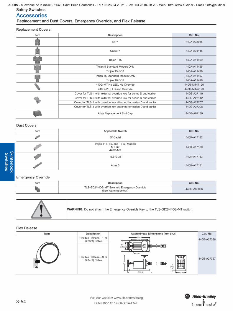
Replacement and Dust Covers, Emergency Override, and Flex Release
General
1-2-O
pto
-electronics
3-Interlock
Sw
itchesO
perato
rInterface
Log
icP
ow
er
R
Replacement Covers
Item Description Cat. No.
Elf™ 440A-A33085
Cadet™ 440A-A21115
Trojan T15 440A-A11499
Trojan 5 Standard Models Only 440A-A11495
Trojan T5 GD2 440A-A11496
Trojan T6 Standard Models Only 440A-A11497
Trojan T6 GD2 440A-A11498
440G-MT No LED, No Override 440G-MT47120
440G-MT LED and Override 440G-MT47123
Cover for TLS-1 with external override key for series D and earlier 440G-A27140
Cover for TLS-3 with external override key for series D and earlier 440G-A27142
Cover for TLS-1 with override key attached for series D and earlier 440G-A27207
Cover for TLS-3 with override key attached for series D and earlier 440G-A27208
Atlas Replacement End Cap 440G-A07180
Dust Covers
Emergency Override
Item Description Cat. No.
TLS-GD2/440G-MT Solenoid Emergency Override(See Warning below.) 440G-A36026
WARNING: Do not attach the Emergency Override Key to the TLS-GD2/440G-MT switch.
Flex Release
Item Applicable Switch Cat. No.
Elf Cadet 440K-A17182
Trojan T15, T5, and T6 All ModelsMT G2
440G-MT440K-A17180
TLS-GD2 440K-A17183
Atlas 5 440K-A17181
Item Description Approximate Dimensions [mm (in.)] Cat. No.
Flexible Release—1 m(3.28 ft) Cable
4 x M5
100 (3.93)
40(1.57)
60(2.36)
8(0.31)
95(3.7)
125 (4.9)
65 (2.55)150 (5.9)
440G-A27356
Flexible Release—3 m(9.84 ft) Cable 440G-A27357
03-SafetySw_2_GuardLock 5/3/2010 2:20 PM Page 3-54
AUDIN - 8, avenue de la malle - 51370 Saint Brice Courcelles - Tel : 03.26.04.20.21 - Fax : 03.26.04.28.20 - Web : http: www.audin.fr - Email : [email protected]

Safety Switches
Accessories
3-55Visit our website: www.ab.com/catalogs
Publication S117-CA001A-EN-P
Tools and Door Handles
Gen
eral
1-2-
Op
to-e
lect
roni
cs3-
Inte
rlo
ckS
witc
hes
Op
erat
or
Inte
rfac
eLo
gic
Po
wer
R
Tools
Item Description Cat. No.
Security Bit 440A-A09015
Screwdriver Including Security Bit 440A-A09018
Door Handles
Item Description Dimensions [mm (in.)] Cat. No.
Sliding bolt actuator
Ø10 (0.39)
20 (0.78)
50 (1.96) 20
19 (0.74)
50 100 (3.93) 42(1.65)
18 (0.7)
Tapped M5
140 (5.51)
117.5 (4.62)
40 (1.57)
34 (1.33)
84 (3
.3)
25.5(1.0)
5.5 (0.21)
20.5(0.8)
24 (0.94)
2.5 (0.09)
440G-A27163
Sliding Bolt
65 (2.56) 55.4(2.18)
6.4 (0.25) Dia.
54.4(2.14)
440K-AMDS
Sliding Bolt MountingPlate for TLS-GD2
73 (2.87)
43(1.69)
6(0.24)
13(0.51)
52(2.05)
125(4.92)
3(0.12)
120 (4.72)
38(1.5)
18(0.71)
60.5(2.38)
17(0.67)
8 (0.32)
52(2.05)
34 (1.36)
23 (0.91)
19(0.75)
7.35 (0.29)65.95 (2.6)105.3 (4.15)
43 (1.69)
8(0.32)
130(5.12)
440K-AMDSSMPB
03-SafetySw_2_GuardLock 5/3/2010 2:20 PM Page 3-55
AUDIN - 8, avenue de la malle - 51370 Saint Brice Courcelles - Tel : 03.26.04.20.21 - Fax : 03.26.04.28.20 - Web : http: www.audin.fr - Email : [email protected]