Embed Size (px)
Citation preview
All critical-flow devices determine flow rate by measuring one or more water levels and computing flow from a calibration equation.
Water Level Sensors and Their Importance
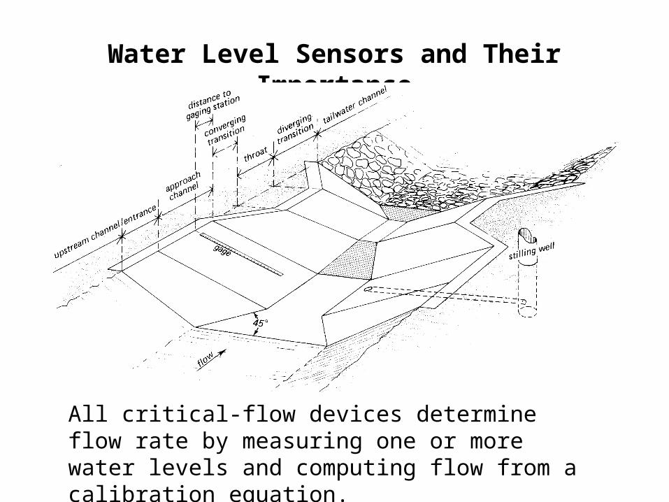
Typical Rating Equation
Q = K1(h1+K2)U
• Even if h1 can be measured perfectly, there is still some uncertainty in the computed discharge– Differences in approach flow conditions
– Uncertainties in theory or calibration methods
– Variations in construction, etc.
• ±2% for long-throated flumes and broad-crested weirs, ±3 to 5% for most lab-calibrated devices operating in recommended ranges
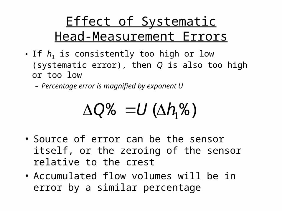
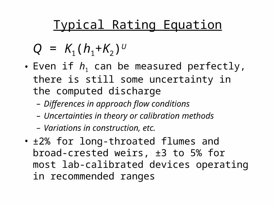
Effect of SystematicHead-Measurement Errors
• If h1 is consistently too high or low (systematic error), then Q is also too high or too low– Percentage error is magnified by exponent U
%)(% 1hUQ
• Source of error can be the sensor itself, or the zeroing of the sensor relative to the crest
• Accumulated flow volumes will be in error by a similar percentage
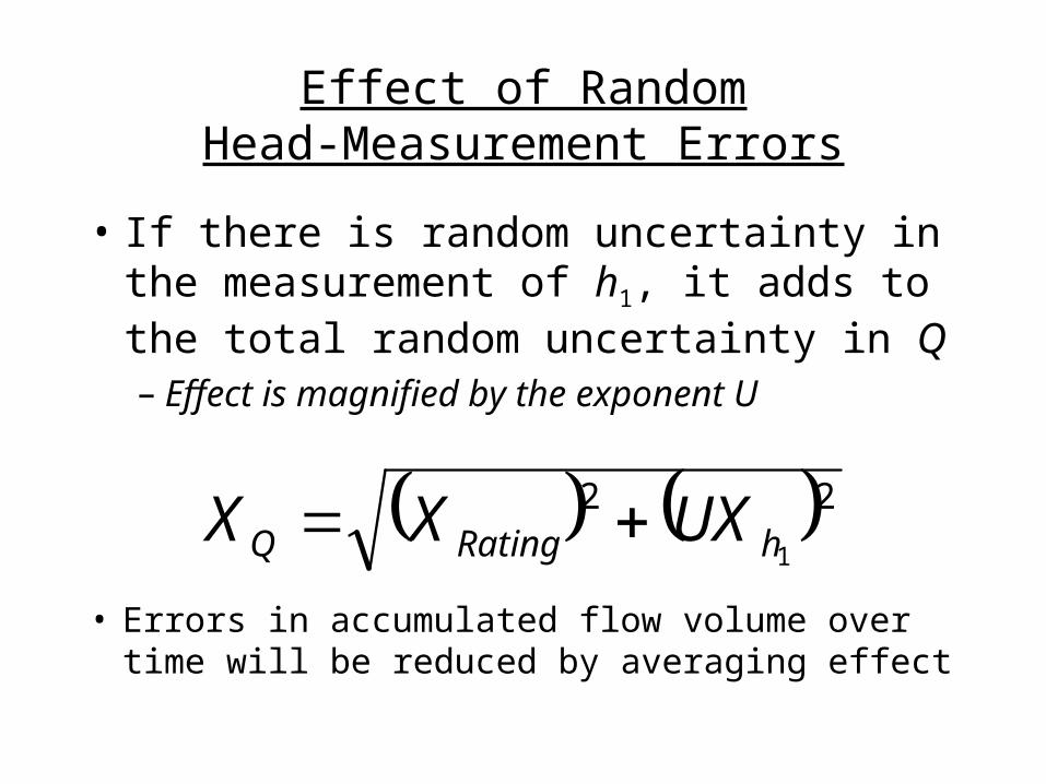
Effect of RandomHead-Measurement Errors
• If there is random uncertainty in the measurement of h1, it adds to the total random uncertainty in Q– Effect is magnified by the exponent U
22
1hRatingQ UXXX • Errors in accumulated flow volume over time will
be reduced by averaging effect
Effects of Flume Design
• Magnitude of systematic or random errors in head measurement is often constant, independent of water level.
• So, a flume or weir that creates a larger head for a given flow rate leads to a lower percentage error in head and lower percentage error in measured flow
Sensor Options
• Direct-reading devices– Staff gages, point gages, dipsticks, etc.
• Floats– Position of float measured by potentiometer, encoder, etc.
• Pressure transducers and bubblers– Measure hydrostatic pressure to determine depth
• Acoustic sensors– Measure water surface by its ability to reflect sound
– Affected by speed of sound travel through air
• Capacitive/resistive sensors
Improving Head-Measurement Accuracy
• Stilling wells– Reduce waves, introduce lag, can become plugged
– Protect sensor, provide more stable environment
• Wave suppressors– Reduce waves, add head loss
• Reduce approach velocity & Froude number– Reduces waves
• Use better sensors
Zero-Referencing of Water Level Sensors and Gages
• #1 source of systematic errors in flume measurements
• Important at small flows because even small errors are large on a percentage basis
• Important at large flows because Q is proportional to h1
U where U is 1.5 to 2.5
Setting water level recorder using a pond
• Place temporary dams upstream of stilling-well pipe and downstream of flume
• Fill pond so that water level is at least 2 inches above crest, or at most common water level for flume operation
• Install recorder and all related equipment in position to record
• Observe recorder output to be sure pond is watertight
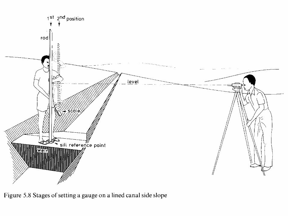
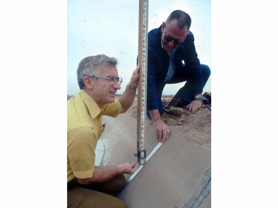
• Read head above crest at control section using a ruler– Control section is 1/4 to 1/3 L from downstream edge of crest
• Adjust recorder to match measured head
• Repeat preceding steps at a different water level
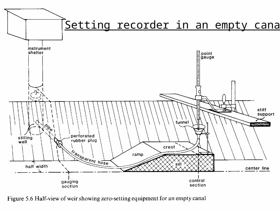
Setting recorder in an empty canal
Setting Recorder in an Empty Canal
• Similar to the pond procedure, but funnel, tubing and stilling well take place of pond
• Measure head at control section using two readings from a point gage mounted on a stiff support
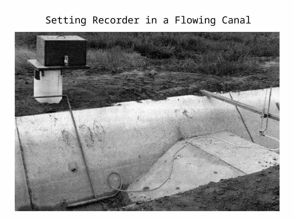
Setting Recorder in a Flowing Canal
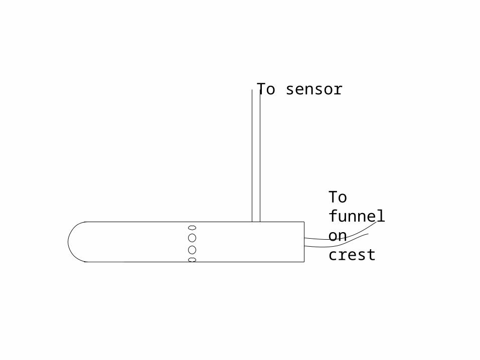
To sensor
To funnelon crest
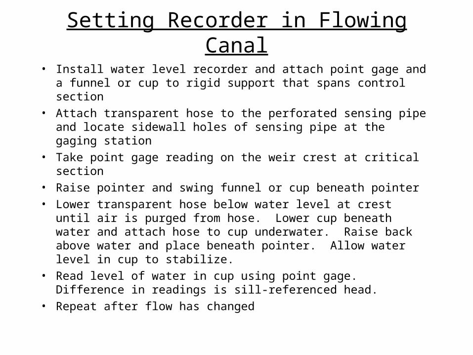
Setting Recorder in Flowing Canal
• Install water level recorder and attach point gage and a funnel or cup to rigid support that spans control section
• Attach transparent hose to the perforated sensing pipe and locate sidewall holes of sensing pipe at the gaging station
• Take point gage reading on the weir crest at critical section
• Raise pointer and swing funnel or cup beneath pointer
• Lower transparent hose below water level at crest until air is purged from hose. Lower cup beneath water and attach hose to cup underwater. Raise back above water and place beneath pointer. Allow water level in cup to stabilize.
• Read level of water in cup using point gage. Difference in readings is sill-referenced head.
• Repeat after flow has changed