Embed Size (px)
Citation preview
One-dimensional water flow
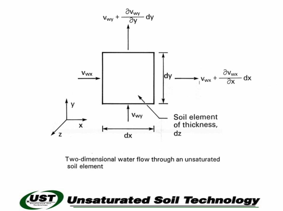
Two-dimensional water flow
3-D water flow
Air flow
Diffusion
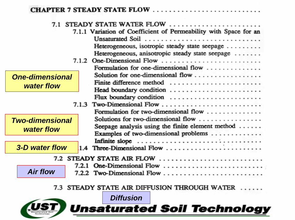
Note that water can flow across the phreatic line
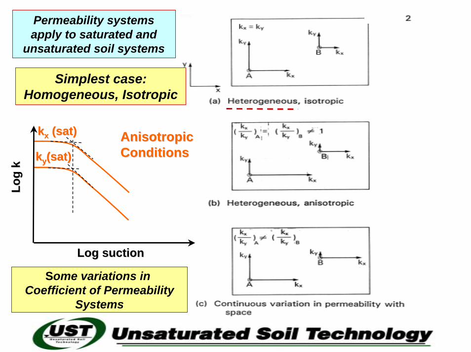
kkyy(sat)(sat)Anisotropic Anisotropic ConditionsConditions
Log
kLo
g k
Log suctionLog suction
kkxx (sat)(sat)
Permeability systems apply to saturated and
unsaturated soil systems
Simplest case: Homogeneous, Isotropic
Some variations in Coefficient of Permeability
Systems
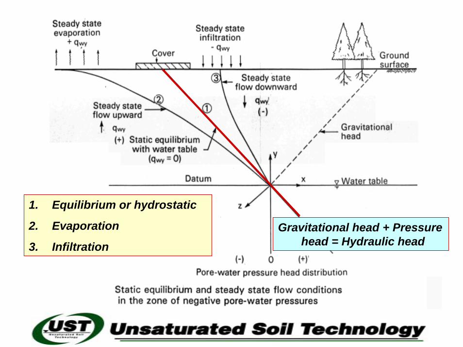
1. Equilibrium or hydrostatic
2. Evaporation
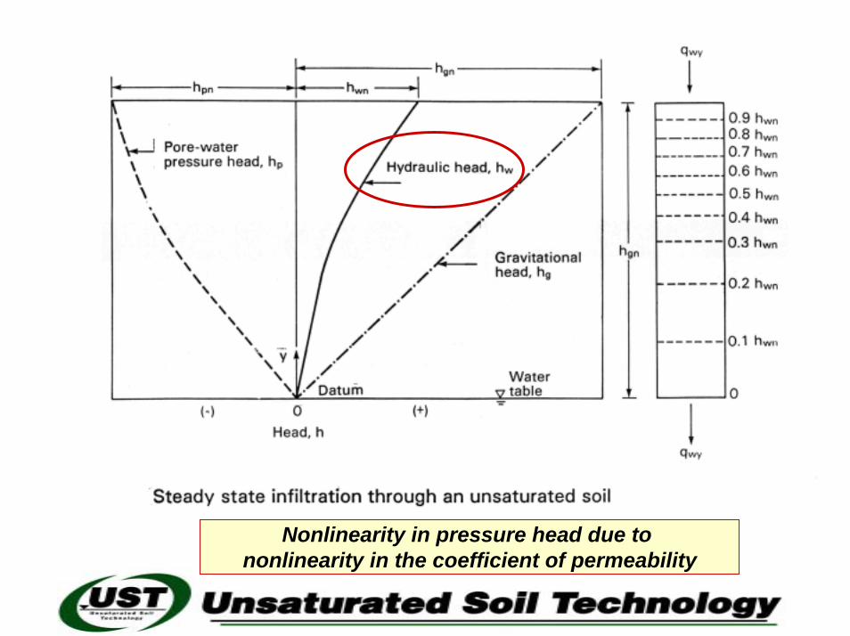
3. InfiltrationGravitational head + Pressure
head = Hydraulic head
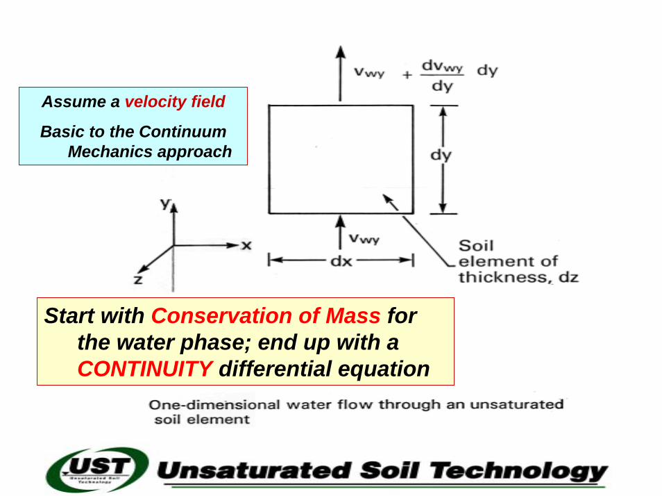
Start with Conservation of Mass for the water phase; end up with a CONTINUITY differential equation
Assume a velocity field
Basic to the Continuum Mechanics approach
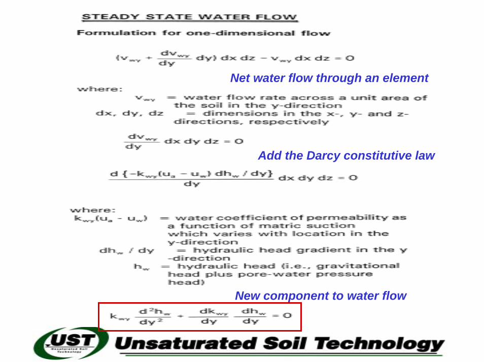
Net water flow through an element
Add the Darcy constitutive law
New component to water flow
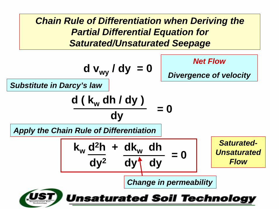
Chain Rule of Differentiation when Deriving the Partial Differential Equation for Saturated/Unsaturated Seepage
d vwy / dy = 0
d ( kw dh / dy )dy
kw d2h + dkw dh dy2 dy dy
= 0
= 0
Net Flow
Divergence of velocitySubstitute in Darcy’s law
Apply the Chain Rule of Differentiation
Change in permeability
Saturated-Unsaturated
Flow
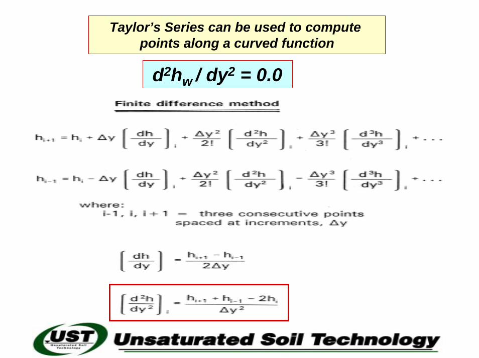
d2hw / dy2 = 0.0
Taylor’s Series can be used to compute points along a curved function
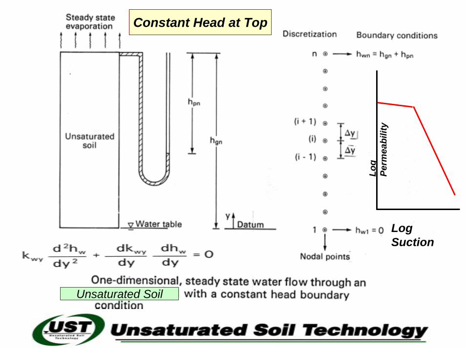
Constant Head at Top
Unsaturated Soil
Log Suction
Log
Perm
eabi
lity
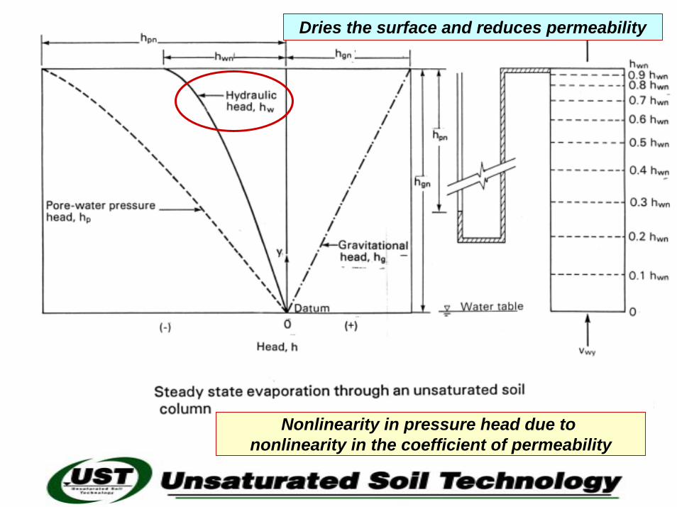
Nonlinearity in pressure head due to nonlinearity in the coefficient of permeability
Dries the surface and reduces permeability
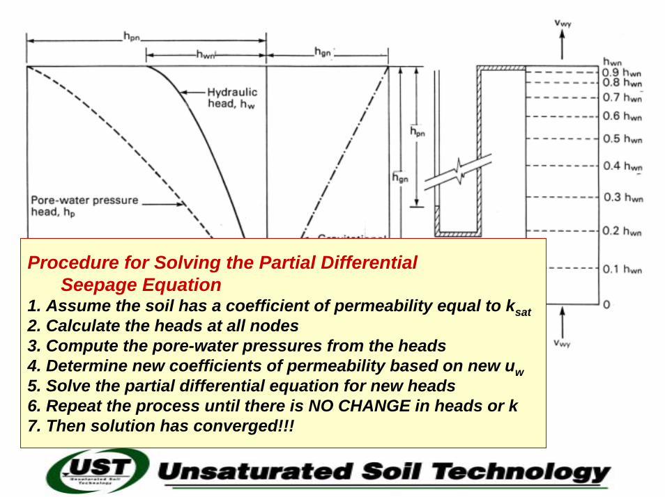
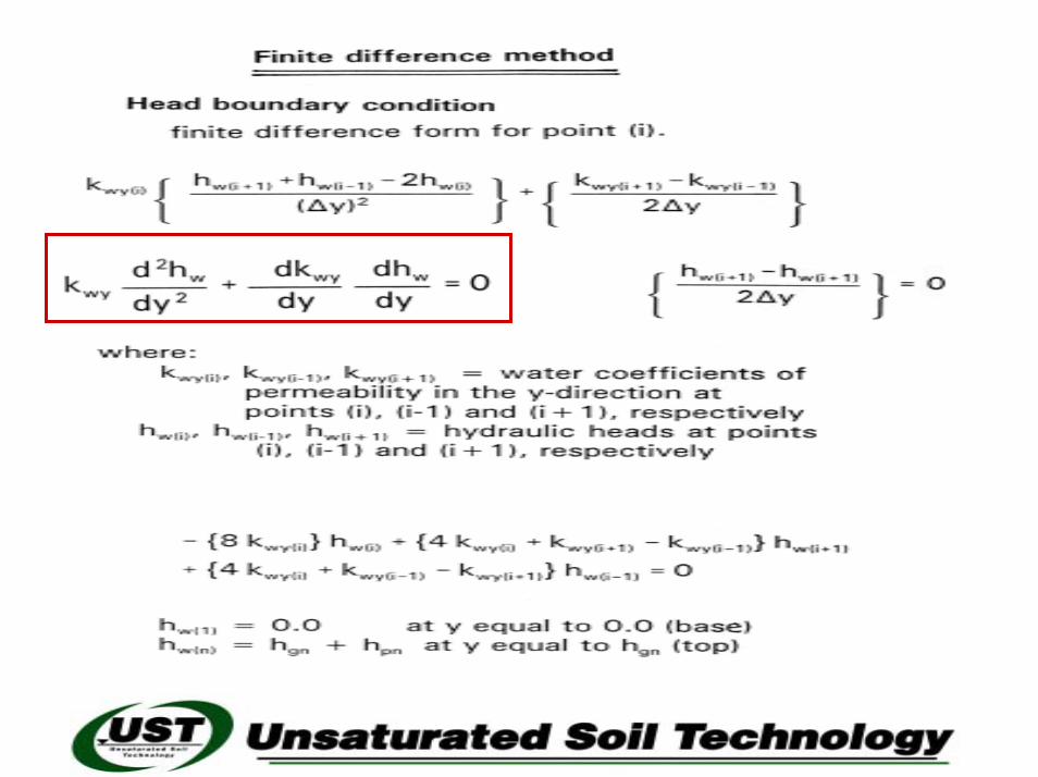
Procedure for Solving the Partial Differential Seepage Equation
1. Assume the soil has a coefficient of permeability equal to ksat2. Calculate the heads at all nodes3. Compute the pore-water pressures from the heads4. Determine new coefficients of permeability based on new uw5. Solve the partial differential equation for new heads6. Repeat the process until there is NO CHANGE in heads or k7. Then solution has converged!!!
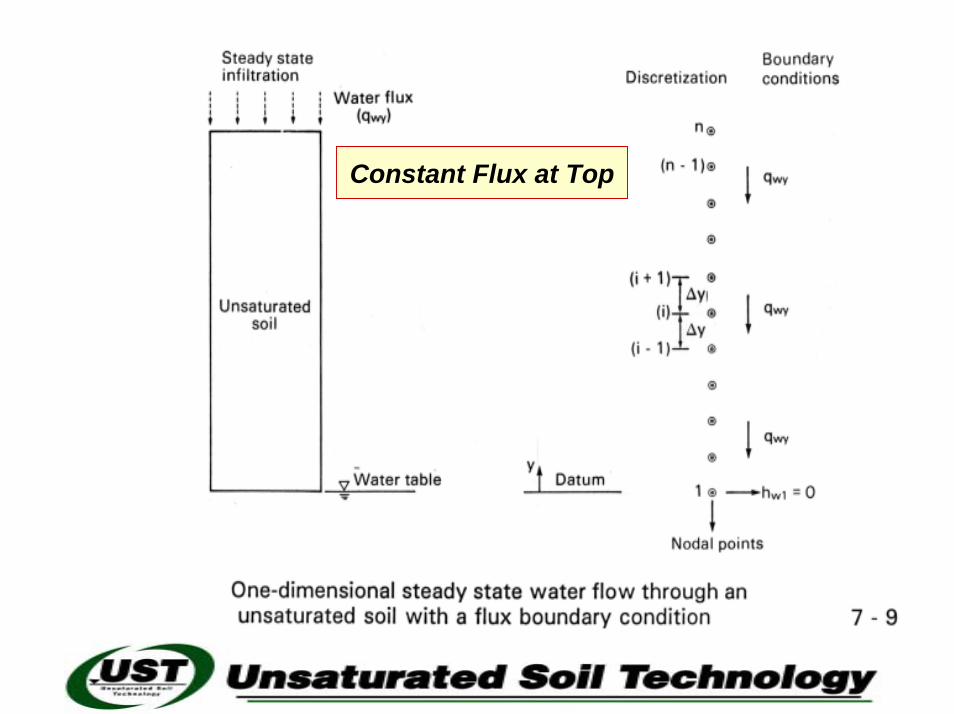
Constant Flux at Top
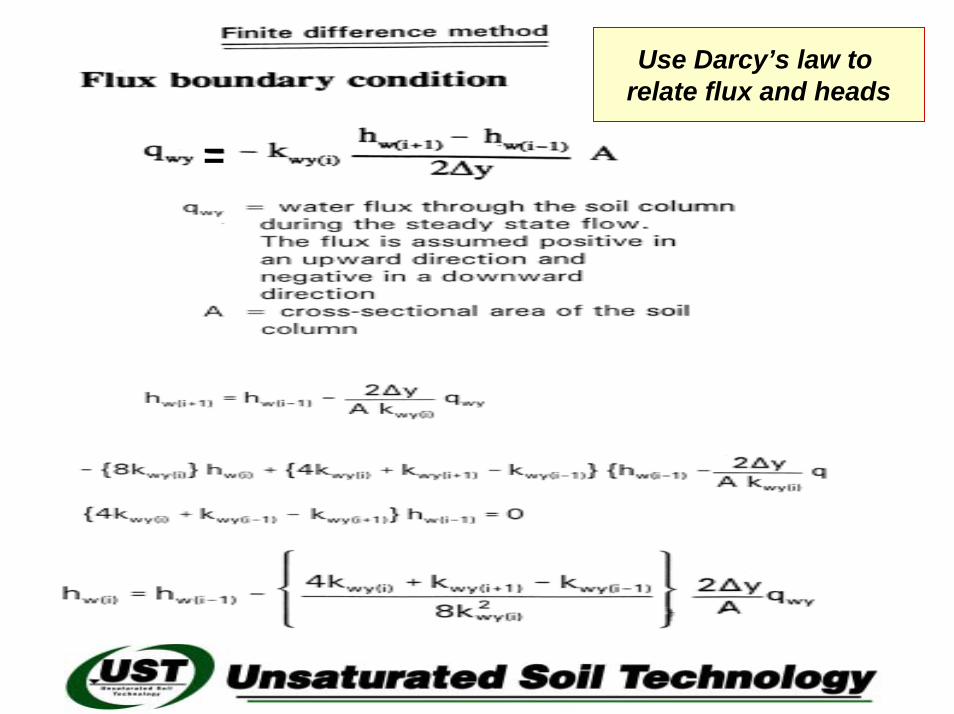
Use Darcy’s law to relate flux and heads
=
Nonlinearity in pressure head due to nonlinearity in the coefficient of permeability
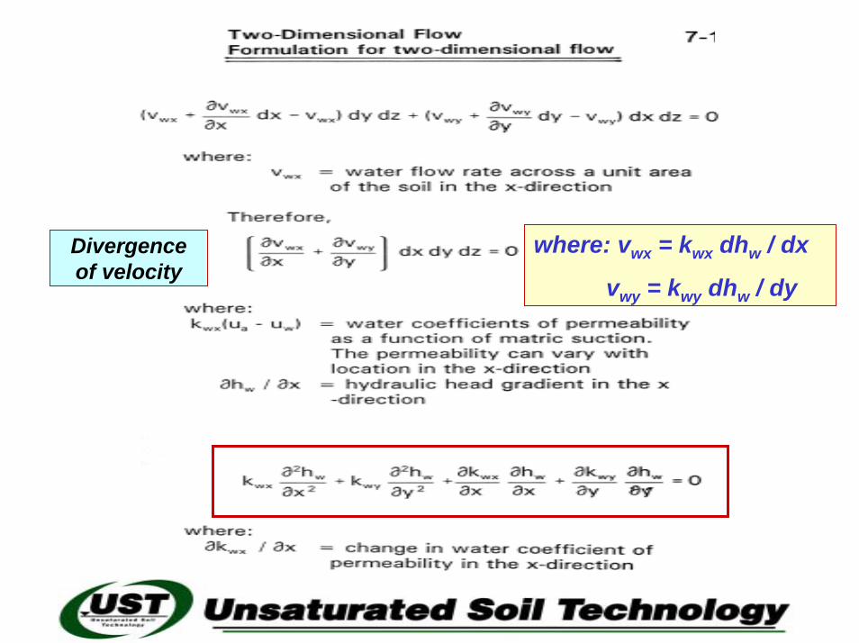
where: vwx = kwx dhw / dx
vwy = kwy dhw / dy
Divergenceof velocity

An unsaturated soil is a heterogeneous soil since permeability varies with space
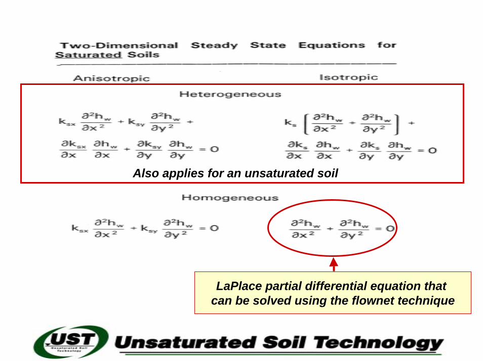
Also applies for an unsaturated soil
LaPlace partial differential equation that can be solved using the flownet technique
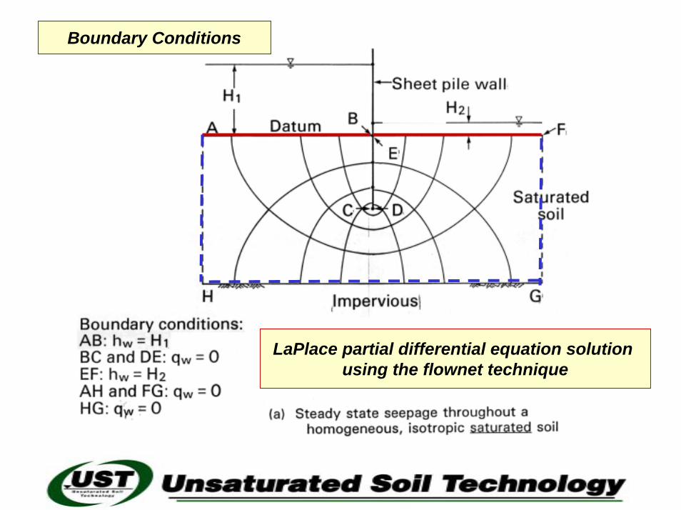
LaPlace partial differential equation solution using the flownet technique
Boundary Conditions
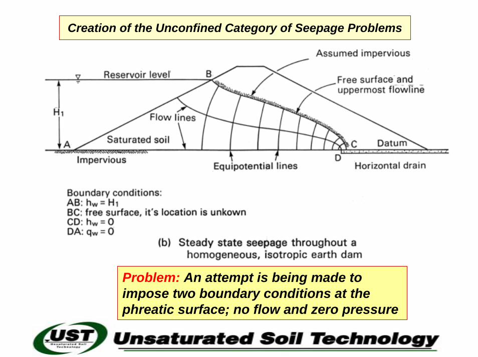
Creation of the Unconfined Category of Seepage Problems
Problem: An attempt is being made to impose two boundary conditions at the phreatic surface; no flow and zero pressure
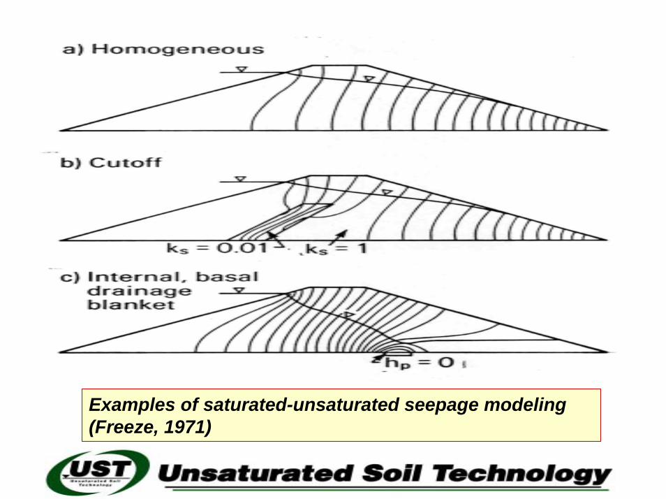
Examples of saturated-unsaturated seepage modeling (Freeze, 1971)
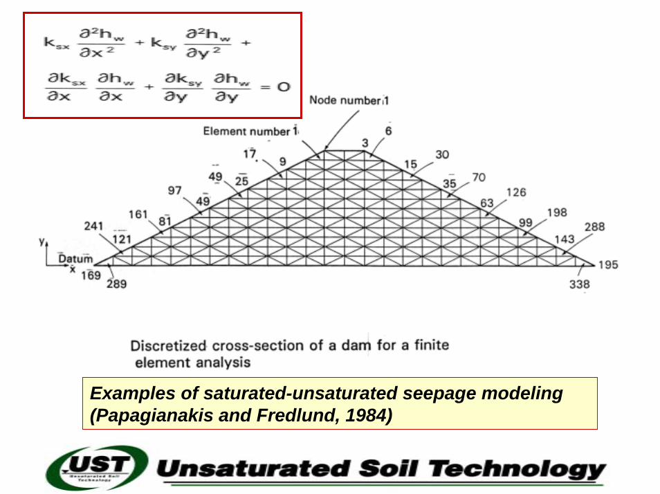
Examples of saturated-unsaturated seepage modeling (Papagianakis and Fredlund, 1984)
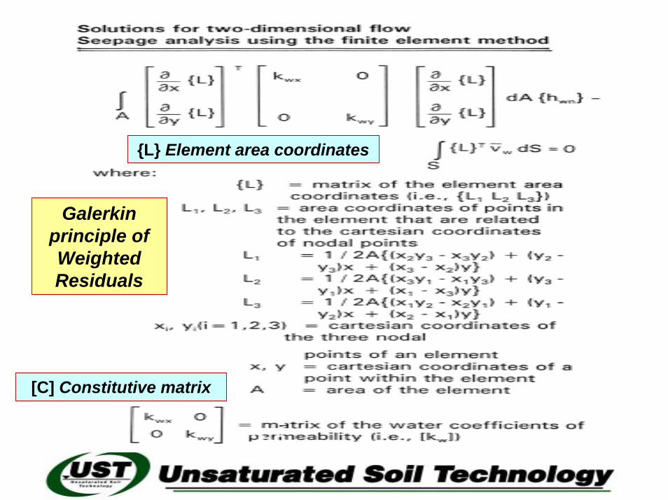
Galerkinprinciple of Weighted Residuals
{L} Element area coordinates
[C] Constitutive matrix
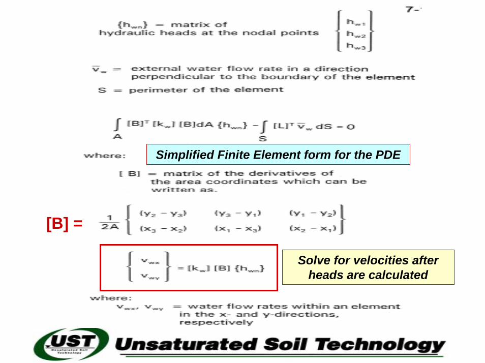
Simplified Finite Element form for the PDE
[B] =
Solve for velocities after heads are calculated

Core of Dam
Shell of Dam
Selected permeability functions
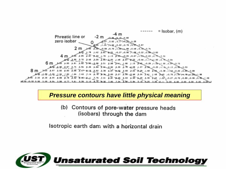
Pressure contours have little physical meaning
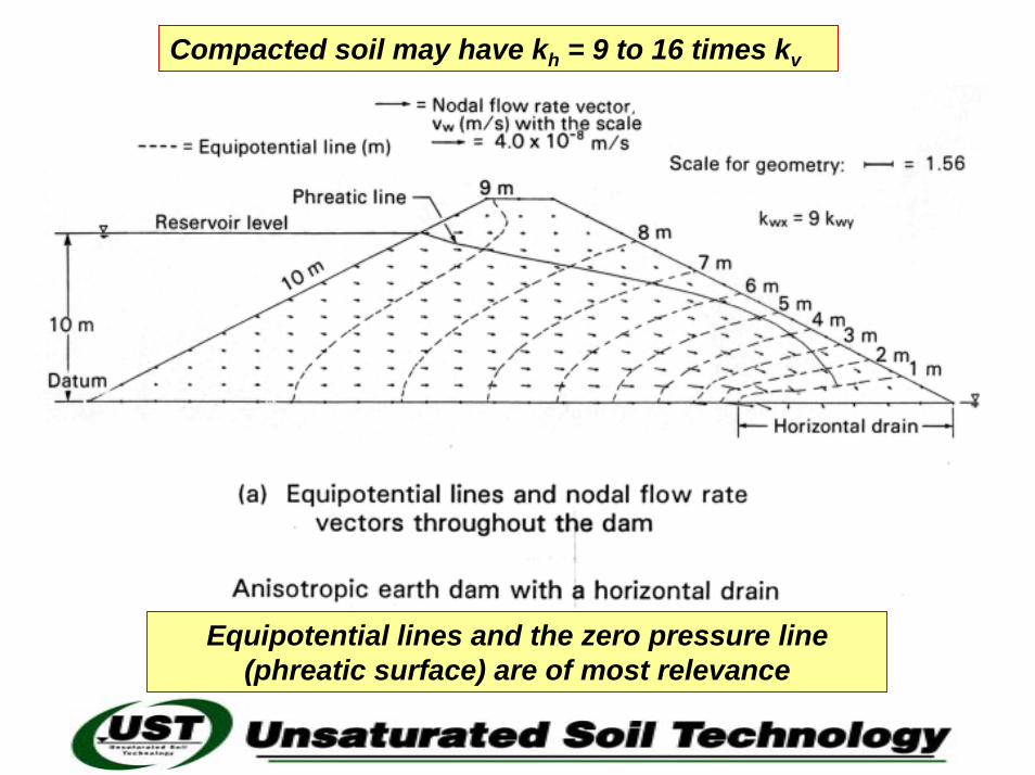
Compacted soil may have kh = 9 to 16 times kv
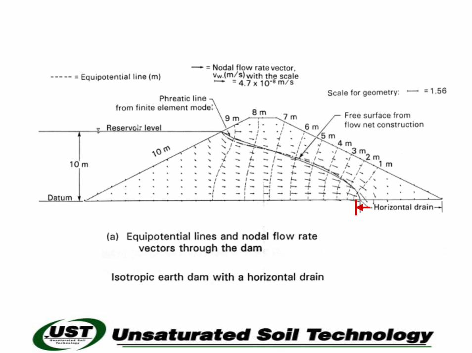
Equipotential lines and the zero pressure line (phreatic surface) are of most relevance
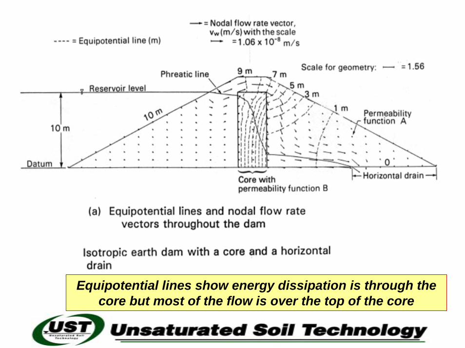
Equipotential lines show energy dissipation is through the core but most of the flow is over the top of the core
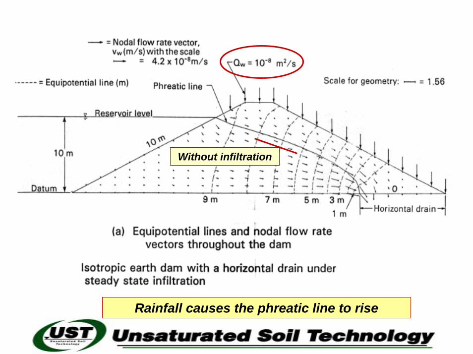
Without infiltration
Rainfall causes the phreatic line to rise
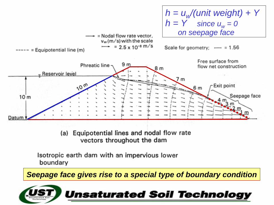
h = uw/(unit weight) + Yh = Y since uw = 0
on seepage face
Seepage face gives rise to a special type of boundary condition
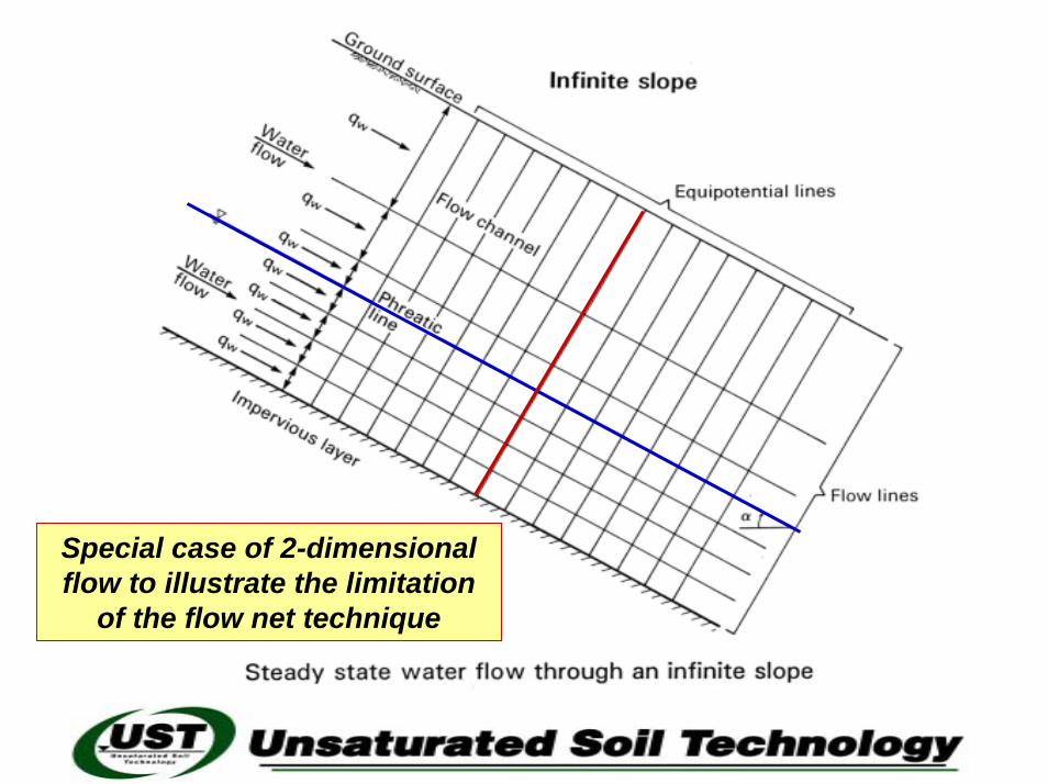
Special case of 2-dimensional flow to illustrate the limitation
of the flow net technique

HH cos αα
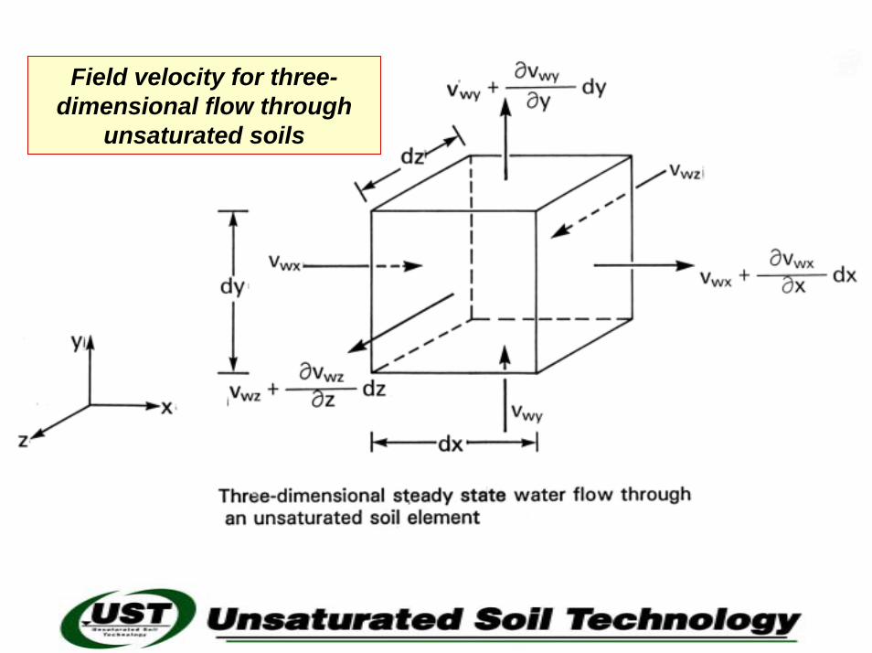
Field velocity for three-dimensional flow through
unsaturated soils
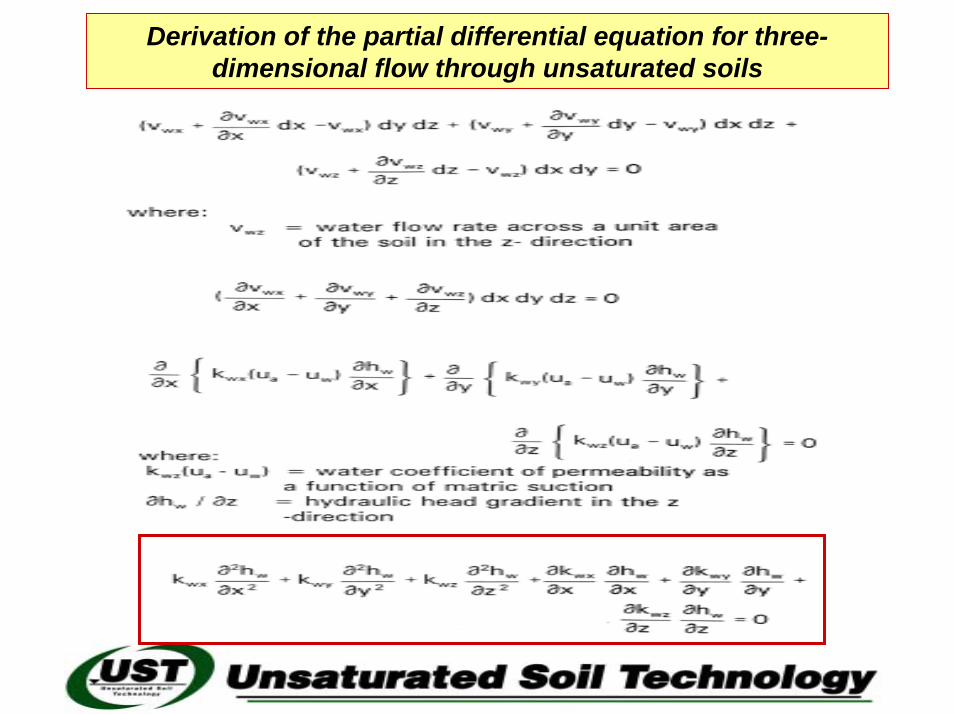
Derivation of the partial differential equation for three-dimensional flow through unsaturated soils