Embed Size (px)
Citation preview
C-RISC A C Language Reduced Instruction
Set Computer
MIKE STARKEY Department of Computer Science
ALI REZA FARHANG Department of Electrical Engineering '
UUCS-90-012
C-RISC
A C language Reduced Instruction
Set Computer
UUCS-90-012
Mike Starkey Department of Computer Science
Ali Reza Farhang Department of Electrical Engineering
University of Utah
Abstract
This project is the implementation of a Reduced Instruction Set Computer (RISC) on a tiny
chip. RISC technology is based on the idea that a small number of simple instructions can be used to
create a fast, flexible computer. Our RISC uses this principle while staying within the confines of the
tiny chip.
Size limitations directly affect the complexity in the number of possible instructions. Since
the tiny chip is limited in size, a decision was required as to the set of instructions to include. Due to
the implementers' knowledge of the C language, it was decided that the direction of the RISe
instructions would follow the C language instruction set, hence the name C-RISe. The decision to
direct the instruction set to the C language instructions does not restrict the flexibility of the C-RISC
since many high level languages (HLLs) can be converted or cross-compiled into C code. The
adoption of a given language direction allows easier comparison of quantitative results when
deciding on instructions to be included in or discarded from the instruction set.
A number of ingenious ideas were incorporated into the design of the C-RISe. These were
necessitated by the small chip size as well as the desired power of the processor. The final C-RISC chip
was implemented in Path Programmable Logic (PPL> [1] using 2 micron CMOS technology.
This report placed third in the 1990 National Tiny Chip competition.
C-RISC: A C LANGUAGE REDUCED INSTRUCTION SET COMPUTER 1
Background
The RISe technology works on the idea that a small set of relatively simple instructions will
provide maximum flexibility and speed. Since implementing an instruction directly can greatly
speed up an operation, the greatest increase in execution speed for a program can be realized if the
most commonly executed instructions are reduced to one RISe instruction. The two most important
instructions in any RISe are load and store due to the large utilization of registers. Only after these
two instructions have been considered, can additional instructions be selected for inclUSion in the
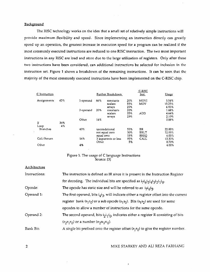
instruction set. Figure 1 shows a breakdown of the remaining instructions. It can be seen that the
majority of the most commonly executed instructions have been implemented on the C-RISe chip.
C Instruction
Assignments
11 Loop
Branches
Call/Return
Other
Architecture
Instructions:
Opcode:
Operand 1:
Operand 2:
Bank Bit:
2
C-RISC further Breakdown Inst. Usage
42% l-operand 66% constants 20% MOVI 5.54% scalars 55% MOV 15.25% arrays 25% 6.93%
2-operand 20% constants 20% 1.68% scalars 55% ADD 4.64% arrays 25% 2.10%
Other 14% 5.88% 36%
4% 40% unconditional 55% BR 22.00%
not equal zero 30% BRLT 12.00% equal zero 15% BREQ 6.00%
14% 3 arguments or less 95% CALL 13.30% Other 5% 0.70%
4% 4.00%
Figure 1. The usage of e language Instructions Source: [3]
The instruction is defined as IR since it is present in the Instruction Register
for decoding. The individual bits are specified as i7i6iSi4i3i2iliO'
The opcode has static size and will be referred to as i7i6iS'
The first operand, bits i4i 3, will indicate either a register offset into the current
register bank (rl rO) or a sub opcode (sl sO), Bits (sl~) are used for some
opcodes to allow a number of instructions for the same opcode.
The second operand, bits i2iliQt indicates either a register R consisting of bits
(r2rlrO) or a number (n2n1nO)'
A single bit prefixed onto the register offset (rlrO) to give the register number.
MIKE STARKEY AND ALI REZA F ARHANG
Condition code: The Condition Code consists of two bits, CN and CZ' These are used for in
dicating negative and zero conditions, respectively. The Condition Code is
calculated from the result of the adder.
Function
TEST INCR NOT COMP MOV
MOVI
CLEAR
ADD
RET STORE
BR BREQ BRLT CALL LOAD
Instruction
OOOOO-L OOOOl..lL OOOlO..lL 0OO11...lL OOlT1TO--.!L
01OrlTon2nlno 01 Or1rcfXXl Ollr1 rO--.!L 10000000 101r1rO--.!L
11000...lL 11001...lL
11010l
11011l 111rI TO--.!L
Figure 2. C-RlSC Instruction Set
Definition
TEST[R] [R] = [R] + 1 [R] = ![R] [R]=-[R] [R] = [BTIrO!
[BrITO! =00000n2n In O
[BrlrO! = OOOOOOOO
[BTlrO! ':' [Brlrol + [R] PC = [BOO]; B = !B M[R] = [BrIrO]
PC=[R] if CNCZ = 01 then PC = [R]
if CNCz = 10 then PC = [R]
B = !B; [BOO] = PC; PC = [R] [BTITO! = M[R]
PC - Program Counter
The opcodes are designed to provide as much information as possible to reduce the amount
of decoding required. The i7 bit is used as an ALU and CC bit. If this bit is 'O'B, the condition codes
are stored for the instruction and the instruction is known to require one clock cycle. The i6 indicates
the destination for storing the result from the instruction. A value of 'O'B for i6 indicates that
operand 2 is the destination, and a value of 'l'B for i6 indicates that operand 1 is the destination. The
instruction set is also designed so that the instruction 'OOOOOOOO'B (TEST) will have little effect on the
chip and its surrounding environment since this instruction is the first instruction in the IR after
resetting the chip. Figure 2 lists C-RlSC's instruction set.
A process called Banking is implemented on the C-RlSC. The eight registers in the register
file are divided into two banks ( Registers 0-3 are in bank one and registers 4-8 are in bank two ).
Since we have only two banks, only one bit is needed to keep track of which bank is currently being
accessed at any time. This bit is called the Bank bit and is maintained internally. Refer to Figures 2
and 6 for more details on how the Bank bit is manipulated. Banking was implemented for two
major reasons; 1) It allowed us to implement more instructions in our instruction set by giving us an
extra bit to work with in the opcode. 2) It gives us a form of data protection during a procedure call.
Having only two banks gives us the ability to have procedure calls up to one level deep. According to
Dr. Katevenis [3], 96% of all procedure calls are four levels deep or less. This would indicate that two
C-RISC: A C LANGUAGE REDUCED INSTRUCTION SET COMPUTER 3
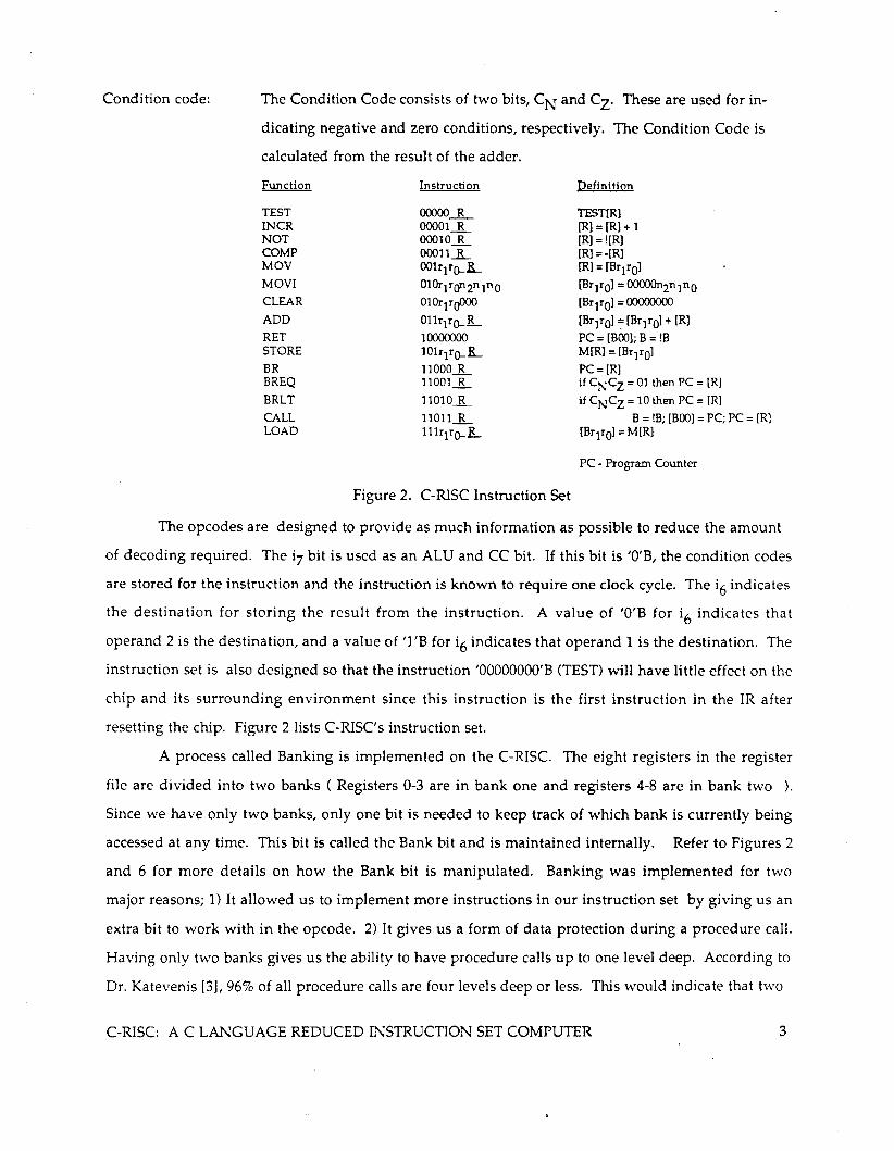
banks are not satisfactory. However, procedure calls of any level can still be implemented with the
C-RISC by using software programs (Part of the Operating System program) which save the contents
of a given bank in main memory before giving write access for that bank to the processor .
.a..-.g .a.-..1.
000 000
L C
00' 00'
0'0 CALL .- 0'0 -0" " 0"
,00 '00
'0' '0' L C
n ... ReT "0 t -", "
Figure 6. Bank Bit Manipulation showing Local Context
Single Clock Cycle Instructions
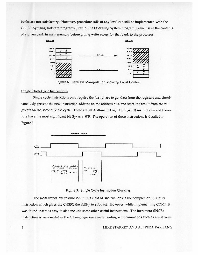
Single cycle instructions only require the first phase to get data from the registers and simul
taneously present the new instruction address on the address bus, and store the result from the re
gisters on the second phase cycle. These are all Arithmetic Logic Unit (ALU) instructions and there
fore have the most significant bit (7) as a 'O'B. The operation of these instructions is detailed in
Figure 3.
•
c:p,---.J cP 21L-____ ----I
Assert the addr . of ne.t In.true.
R] or (B,.,.] or n n n >- Alu o , ..
Prefetch
Alu >- (R) or
[B rr)
Figure 3. Single Cycle Instruction Clocking
L
The most important instruction in this class of instructions is the complement (COMP)
instruction which gives the C-RISC the ability to subtract. However, while implementing COMP, it
was found that it is easy to also include some other useful instructions. The increment (lNCR)
instruction is very useful in the C Language since incrementing with commands such as i++ is very
4 MIKE STARKEY AND ALI REZA F ARHANG
commonly used. The test (TEST) instruction is also very useful for setting the Condition Codes for a
value in a register. The not (NOT) instruction, which inverts all bits, falls out as a side effect and may
be useful. These instructions are implemented by EXORing the bits of the operand with i4 and then
adding i3 to the result.
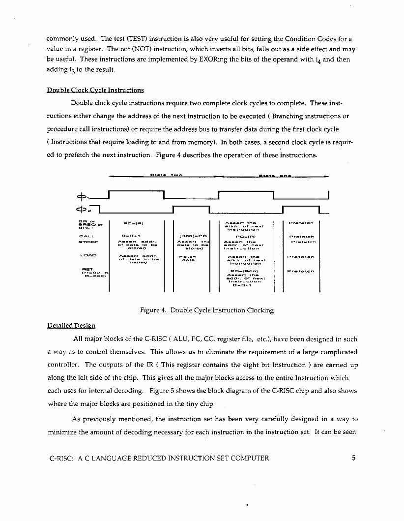
Double Clock Cycle Instructions
Double clock cycle instructions require two complete clock cycles to complete. These inst
ructions either change the address of the next instruction to be executed ( Branching instructions or
procedure call instructions) or require the address bus to transfer data during the first clock cycle
( Instructions that require loading to and from memory). In both cases, a second clock cycle is requir
ed to prefetch the next instruction. Figure 4 describes the operation of these instructions.
8't_te t'WYO
c:p1_ ...... c:p .:IL... _____ ..... SA Or BREa Or BRLT
CALL
STC»AE
LC>AD
A •• e..-t addr. of data. to be
A ___ ,.t: _dd,..
of a .... tEl. to be loaded
[Beel-PC
A.._erl tM data to be
etored
Fetch data.
0,.,. 00-
A ••• rt th_ addr. of next Inatruc:tlo n
A ___ rt: th_
addr. of ,.., .. X1: Instruction
A._ .. rt th_ edch', of naxt Instruction
pc_[eCO) A .... rt th _
_ dldr, of next Inat.ructlC3n
B_6_"1
P,..f_tc:h
Prefe1:ch
Prefetcn
Pref_tch
Pr.f_tch
Figure 4. Double Cycle Instruction Clocking
Detailed Design
L
All major blocks of the C-RISC ( ALU, PC, CC, register file, etc.), have been designed in such
a way as to control themselves. This allows us to eliminate the requirement of a large complicated
controller. The outputs of the IR ( This register contains the eight bit Instruction) are carried up
along the left side of the chip. This gives all the major blocks access to the entire Instruction which
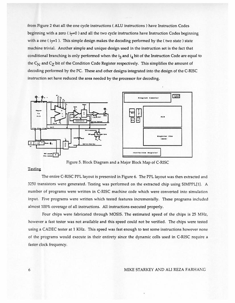
each uses for internal decoding. Figure 5 shows the block diagram of the C-RISC chip and also shows
where the major blocks are positioned in the tiny chip.
As previously mentioned, the instruction set has been very carefully designed in a way to
minimize the amount of decoding necessary for each instruction in the instruction set. It can be seen
C-RISC: A C LANGUAGE REDUCED INSTRUCTION SET COMPUTER 5
from Figure 2 that all the one cycle instructions ( ALU instructions) have Instruction Codes
beginning with a zero ( i7=0 ) and all the two cycle instructions have Instruction Codes beginning
with a one ( i7=1 ). This simple design makes the decoding performed by the ( two state) state
machine trivial. Another simple and unique design used in the instruction set is the fact that
conditional branching is only performed when the i3 and i4 bit of the Instruction Code are equal to
the CN and Cz bit of the Condition Code Register respectively. This simplifies the amount of
decoding performed by the Pc. These and other designs integrated into the design of the C-RISC
instruction set have reduced the area needed by the processor for decoding.
Testing
BIT] BEl
...
••• '.'er ru. t ••• )
, ..... c" ••• '."'.' I Figure 5. Block Diagram and a Major Block Map of C-RISC
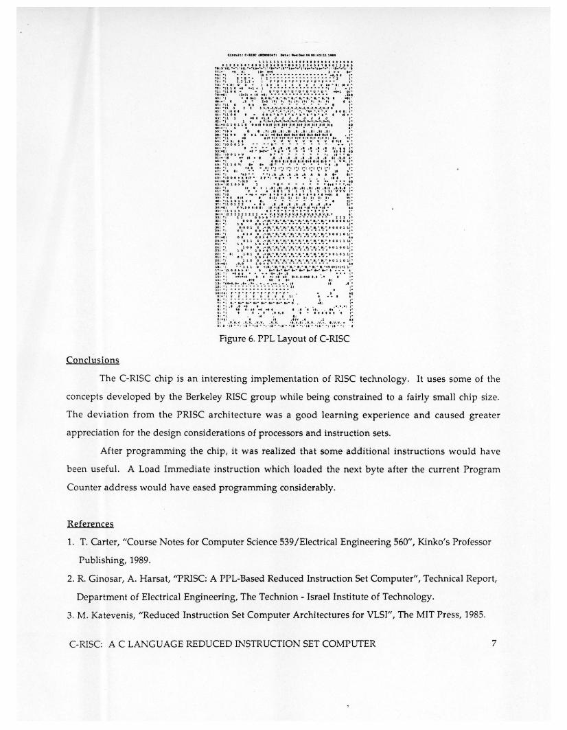
The entire C-RISC PPL layout is presented in Figure 6. The PPL layout was then extracted and
3250 transistors were generated. Testing was performed on the extracted chip using SIMPPL[l] . A
number of programs were written in C-RISC machine code which were converted into simulation
input. Five programs were written which tested features incrementally. These programs included
almost 100% coverage of all instructions. All instructions executed properly.
Four chips were fabricated through MOSIS. The estimated speed of the chips is 25 MHz,
however a fast tester was not available and this speed could not be verified . The chips were tested
using a CADEC tester at 1 KHz. This speed was fast enough to test some instructions however none
of the programs would execute in their entirety since the dynamic cells used in C-RISC require a
faster clock frequency.
6 MIKE STARKEY AND ALI REZA F ARHANG
1111111111", ••••• "".,11 0 1 1' f •• , •• 0 11 •• I ., •• 0 1 I ,. " , •• 0 1 I , •• '" •.••. ~ .. , ' •• , ~ .. ~ .... -.. ~ , . 'I"··· I '-~''''···I ' ............... , . ' ........ '.
" : . ' ... , , ,.... J •• I· ' " : . , . . .. .. " .. .... .... . . .. ................. , .. " : " , 1]· · · ........ • ...... • .. • .. ···1 , .. ,.: ., 1 , 1 1 , 1_ ". ,.,., .. , .. ,., .. ,.... , . ,,: . «., 0 O . " r r r r r r r r .... II , . » • " : ",110 -t .·1. I ..... .... .. .......... .. ... , I .,. ": - ' 1 I. • ., 0·0 - iii · " ·0 ." • iii " "" ... 1 I,· '0 : -0 1 '''' 1 • ,t .' 1 .. .............. .... .... . 1.0 " : 'I .. 1,'1 0 , 0 G. · G. · G. - ' • • G.· C. · . . .. G.·.. -t, . ,,:. ' , .... 1·. "1 ., " ,. , ,. , ., "'1 •• ' " : " ' 1 0 I a .. .. .. .. .... - ... , • • , : · '1 1 1 1 1 ».v,J. V. J . v. J . v.J . v.J . v . J . v . J . V. J I , . " : ·" '11 . •. •• ••• . • , ... " . ........... III , , .. N : · ,100 .. . ... ·a ·.· ....... ·•· I ,.,. tl : ·,1 1 ... -1 . , J J J J J J J J , .. U : . , 1.. " ,-. ,_' , ... , _. ,_. ,_. , -. , ... , , .. tl : ·"110 11 I •• 11. "' '1' Jit '1' '1' "t J , •• " '1, 141 to : · ·, 1. . .. . - . . .. .. , . •• : . ,.. I 1 . ' 1. 11 . 1 ,. 11 . 1 '.11.1 , . 11 . 11 , -M : " '1 00 •• 1 'II, -t ...... II •••••••••••• t. . ,. :! ~ :';.1 .;0 0'· .~ .. ~. -"'. ~, . :'. :'. ; ,.; ' : .• " ;': »: ~ ,o 0 0 1 » ••• .. •• • .. • • .. •• •• , ..
~ ; .; : •. ~: .... ,:. ". ,'. " . . ~ .! .! .~ .~ J~, If!; N ; ·,001. V I· ........ " ... , , •• • It · 11 : · ' " ... II -. . • . I . I .• • • •• . • • J.I •• • • . • • 10: .,. • ." II •• , •• , •• ,. I , . I I'. , V V. '" " : · 11 1 0 " ... ... , . . " .. • • .. ~ -. . . ., ..
:~ ~ : ' " . , .J .. '. • .. ' ! , .~ '.,,' , .... , I:' I: ' I: ' ': ' I:' ,I »': •• : .. , • • , .. .. .. .. I .................... I" . , • • , : "' 000» •• .,.. J," , .,. .. • • . . . ". ,. " : -011 " . J" .. - _ .. 141 ., : - · ,0 1 '» • I ............. t,. - .. .. . " tt : " f ,. 0 • f . 11 . 1 ' . 1 ' . 11 . 11 . 1 ' . 1 ' . 111 . ' . 1 . ' ,. n : ",0 r.' •• 1 1 1 1 1 1 11, V V V ,. '0 : · ,0 .. .... ,... •••• I ......... I ••• 000 " ' f" n : ~ ". . .' '"I. I . I f I , I , I I I . I I y , ~ II : ~ ,1 1 0 1 1 • I • . .............. I '· n : " u 01 I I ••• • • • 1 • • • • • 1.1.. . .. 1 ' · " : -cl i \I \I . " '" I ' , . - •• -I' ..•. , •. U . , . -.1 - •• n : . tl 1 1 , • 1 • I ~ I ~ I - I .. I ~ 1 .. I ~ , . )1 ' '' ' ' 1 I II 1 I 1 II • _ ... . . 0, . 1 \/ . ' v . I V.I 0, . 1 V.' V.... •. ,, : " I 1 , 0 0 » ... .. ... ~ .. • • .. • .. • .. • .. I 1 1 . " aa ;". '00 O .• ,. , ...... . . • • • ·., .... • • • ~ • • ·,.O •• l'· ' 1: .. . 1 • 0 • , • ~ ...... .... .. .. ... ..... ~ .. • , . JO :" .1001 0 •• 1 . . ........ • • • ~ .. .. . . • • • • . ... . 00011 . .. " : ". 0 1 0 • » . .. " .. .. " ...... ~ .... ... ~ ~ • ,. I. :". 0 1 0 • •• "' ... . . • • • ~ .. . • .. . " • • • . . ...... ... 101 '· Il : -Cl i 00 OO •• - ~ .... ~ · .... ·~·~ ·· ~· •• I.:·', 011 0 . • , .. . • . ... . . • • . • . ... . . .... . ~ . ... . 00111. · 110 : .. , 1 1 1 0 , .... ... ~ • • • .. • .. • .. .. • , .. ,, :~, 100 0 •• , . ... . ... . ... . ... . ,· .. . .... ...... . 01.0 1' .. J, : "I 1 0 1 0 » •• ~ ..... " • " .. • • • • .. • • , . JI '· " 101 • • • , • • • • • • • • • . ... . . • • . • • • • . ... . 01011 ' .. 11 : ~ I 0 1 1 • » • • .. • • • • • • • .. • • .. .. • • , ~
10:·, 11 00 .• ' • . ·., ·.,· • . • • . " • • • . ... . . ·.0110 1'· " : -CIt . 0 . 0 1 0 » • ~ ~ ..... " ~ •••• " .. ~ • •• 11 : . , ... 1 1 1 0 . ' 11 ... . , · II . · III.· III , ~ .. . .... ... . .. 0-1·1-1 l' . 11 : - ,100' ~ . ' I ........... " .. .. ... .. . .. ~ .. . J ...... , . 11: '" ..... .. - •• ' 1- • •• • I • ... , ~
1 ' :'" ............ , ..... . . . . ".... . . " .. 11 ; · , . ••• • ••• - II , . 1' : ~ , ... . .. . .. . ... . . . _ . ... • • • .. It • • ~
u :·, .. ·~ ··· .. ·~·· · ~ · .. ~ l' I " u : ... " ........ .. ...... . .. .. ~ , I~
1: ~ :~ : ~ . : . ~ . : .. : . : .: ".r· l' ,_'_.:~ , : " , .. .. . . ~ ~ ~ ..... .. . . " , J , . , : .. , C. " ... • c.- " .... ~ . ... . ........ ~ 0 • 000 , , ~ ,: " ... ,'-. . . ...... " . . ,., ... .... ..... ... , ... . , . '" .: .. , . . . ..... . ....... '" : ; .. ; ~ ' . ,. i. .: .'.., .' .J l: 1: . . v. , . e .v.v •• v. v. .\/. V. " .•. 1 ' . v. v .. v .... , . v. v. . . 0: ' ·,. · .. . ·, . .. .. '. · ·1·' . .... ., .... .. · .. ,· •• · "'. · "' ·1. "" ' ·
Figure 6. PPL Layout of C-RISC
Conclusions
The C-RISC chip is an interesting implementation of RISC technology. It uses some of the
concepts developed by the Berkeley RISC group while being constrained to a fairly small chip size.
The deviation from the PRISC architecture was a good learning experience and caused greater
appreciation for the design considerations of processors and instruction sets.
After programming the chip, it was realized that some additional instructions would have
been useful. A Load Immediate instruction which loaded the next byte after the current Program
Counter address would have eased programming considerably.
References
1. T. Carter, "Course Notes for Computer Science 539/Electrical Engineering 560", Kinko's Professor
Publishing, 1989.
2. R. Ginosar, A. Harsat, "PRISC: A PPL-Based Reduced Instruction Set Computer", Technical Report,
Department of Electrical Engineering, The Technion - Israel Institute of Technology.
3. M. Katevenis, "Reduced Instruction Set Computer Architectures for VLSI", The MIT Press, 1985.
C-RISC: A C LANGUAGE REDUCED IN$TRUCTION SET COMPUTER 7