Embed Size (px)
Citation preview
PN 55115
Alere™ Universal Printer User Manual

Contents1. Product Description ...........................................................................1
1.1 Introduction ..............................................................................................................1
1.2 Material List ..............................................................................................................1
1.3 Printer Installation Position .......................................................................................1
1.4 Power Adapter Connection ......................................................................................1
1.5 Communication Cable Connection ..........................................................................2
2. Printer Operation ................................................................................22.1 Appearance and Module .........................................................................................2
2.2 Introduction of Main Module .....................................................................................3
2.3 Function of LED and Button ......................................................................................3
2.3.1 Function of LED ................................................................................................3
2.3.2 Function of Button ...........................................................................................3
2.3.3 LED ..................................................................................................................3
2.3.4 Function of Button Configuration ....................................................................4
2.4 Paper Loading ...........................................................................................................4
2.5 Start the Printer ........................................................................................................5
2.5.1 Power ON and Self-Test ..................................................................................5
2.5.2 Print Self-Test Page .........................................................................................6
2.5.3 Label Verification .............................................................................................6
3. Printer Adjustment .............................................................................73.1 Adjustment of Parameters .........................................................................................7
3.1.1 Adjustment and Adjustment Range .................................................................7
4. Routine Maintenance .........................................................................74.1 Cleaning the Print Head ..........................................................................................7
4.2 Cleaning the Sensor Cover .....................................................................................8
4.3 Cleaning the Print Roller ...........................................................................................8
5. Troubleshooting ..................................................................................95.1 LED Status Indication ...............................................................................................9
5.2 Printing Quality Problem ..........................................................................................9
Appendix ...............................................................................................10Appendix 1. Technical Specification .............................................................................10
Appendix 1.1 Main Technical Specifications ..........................................................10
Appendix 1.2 Paper Technical Specifications .........................................................11
Appendix 2. Self-Test Page ...........................................................................................11
Appendix 3. Button Configuration .................................................................................13
Appendix 4. Printing and Paper Out Position ...............................................................16
Appendix 5. Communication Interface ..........................................................................17
Appendix 5.1 Serial Interface ..................................................................................17
Appendix 5.2 USB Interface ....................................................................................17
Appendix 6 Guidance and Manufacturer’s Declaration –Electromagnetic Emissions ..18
Glossary of Terms and Symbols..........................................................22
Contact Alere .......................................................................................23
Safety and PrecautionsBefore installing and using the printer, please read the following items carefully.
1. Caution Do not touch the print head during printing and just after operation. It is a thermal element and can reach a high temperature. Contact with the print head can cause a minor burn.
Keep the printer away from water to avoid a shock hazard and equipment damage.
Keep the printer out of moist areas to avoid condensation. If condensation occurs, do not turn on the power until it has completely gone away. Condensation build up could cause minor shock.
Disconnect the power when the printer is not in use.
Do not spill water or other conductive materials into the printer (e.g. metal). If this happens, turn off the power immediately.
Do not disassemble the printer.
2. Important• Install the printer on a flat and stable surface.
• Reserve adequate space around the printer so that the operation and maintenance can be performed properly.
• Do not use or store the printer in a place exposed to heat, moisture or serious pollution.
• Do not place the printer in a place exposed to vibration or impact.
• Do not touch the print head. It is an ESD-sensitive device.
• Do not expose the printer to direct sunlight, strong light or heat.
• Connect the printer power to an appropriate outlet. Avoid sharing one electrical outlet with large instruments or other devices that may cause the fluctuation of voltage.
• Do not attempt to print when there is no paper installed, otherwise the print head and roller will be damaged.
• To ensure quality print and normal lifetime, use the recommended paper.
• Shut down the printer when connecting or disconnecting data cables to avoid damages to control board.
• Set the print darkness to a lower grade as long as the print quality is acceptable. This will help to keep the print head durable.
• Keep this manual carefully in hand for reference.
Waste Disposal Council Directive 2002/96/EC concerning Waste Electrical and Electronic Equipment (WEEE). Indicates a requirement not to dispose of WEEE as municipal waste. Contact your local distributor for information regarding disposal of the unit and accessories.

1Alere™ Universal Printer User Manual
1. Product Description1.1 IntroductionAlere™ Universal Printer is a high performance thermal label printer with a simple structure for easy operation. It adopts modular design and can accept up to an 80mm (maximal diameter) paper roll. Equipped with serial and USB ports, the printer provides real-time printing when connected with the testing device.
Main Features:• Thermal printing.• Low noise, 150mm/s high speed printing.• Easy paper loading, convenient operation, easy to use.• 32 bit high speed microprocessor.• Automatically temperature controlled, and high printing quality.
• ESC/POS programming language.
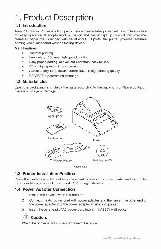
1.2 Material ListOpen the packaging, and check the parts according to the packing list. Please contact if there is shortage or damage.
CD
Multilingual CDPower Adapter
User ManualPrinter
Paper Spool
Figure 1.2.1
1.3 Printer Installation PositionPlace the printer on a flat stable surface that is free of moisture, water and dust. The maximum tilt angle should not exceed ±15° during installation.
1.4 Power Adapter Connection1. Ensure the power switch is turned off.
2. Connect the AC power cord with power adapter, and then insert the other end of the power adapter into the power adapter interface of printer.
3. Insert the other end of AC power cord into a 110V/220V wall socket.
Caution:When the printer is not in use, disconnect the power.
2 Alere™ Universal Printer User Manual
1.5 Communication Cable Connection1. Confirm the power of printer is turned off.
2. Insert the data cable to the suitable interface on the back of the printer, and fixed it with a screw or clip spring.
3. Connect other end of the communication cable to the testing device.
Important:Do not connect or disconnect the serial or USB data cable when the power is on.
2. Printer Operation2.1 Appearance and Module
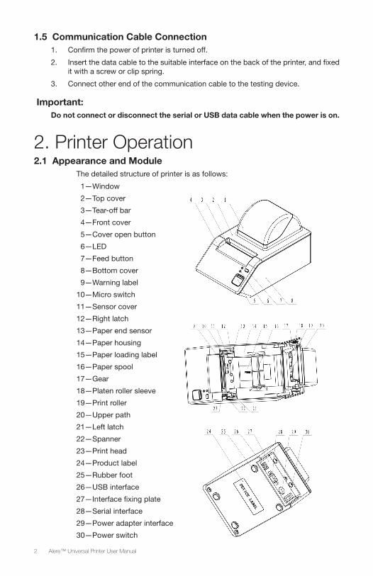
The detailed structure of printer is as follows:
1—Window
2—Top cover
3—Tear-off bar
4—Front cover
5—Cover open button
6—LED
7—Feed button
8—Bottom cover
9—Warning label
10—Micro switch
11—Sensor cover
12—Right latch
13—Paper end sensor
14—Paper housing
15—Paper loading label
16—Paper spool
17—Gear
18—Platen roller sleeve
19—Print roller
20—Upper path
21—Left latch
22—Spanner
23—Print head
24—Product label
25—Rubber foot
26—USB interface
27—Interface fixing plate
28—Serial interface
29—Power adapter interface
30—Power switch
3Alere™ Universal Printer User Manual
2.2 Introduction of Main Module1. Paper spool (16): to support paper roll.
2. Micro switch (10): to detect print head lift up/press down.
3. Paper end sensor (13): to detect and position media like label paper, etc.
4. Power switch (30): power control switch of printer.
2.3 Function of LED and Button2.3.1 Function of LED
LED name Status Explanation
Power LED (green) Always On Printer power is on
Error LED (red) Flashing Printer error.
Table 2.3.1
2.3.2 Function of Button
Button Function Explanation
Feed button
Press down button to feed paper
For label printing: the printer only feeds one label; for continuous paper (paper without hole cut-outs), the printer does not stop feeding paper until the button is released.
Print self-test page
If turning on the power while pressing down the feed button, the printer will print out the main menu. According to the menu’s operation prompt, select “print configuration information” through the feed button. For operation steps, please refer to 2.5.1.
Parameter configurationRefer to appendix 3 to modify the printer parameters.
Sensor verificationFor sensor verification method, please refer to 2.5.3.
Table 2.3.2
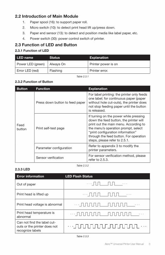
2.3.3 LED
Error information LED Flash Status
Out of paper
Print head is lifted up
Print head voltage is abnormal
Print head temperature is abnormal
Can not find the label cut-outs or the printer does not recognize labels
Table 2.3.3
4 Alere™ Universal Printer User Manual
2.3.4 Function of Button Configuration
Parameters can be configured via long-press time or short-press time according to the printed configuration information. For the detailed configuration information, please refer to appendix 3.
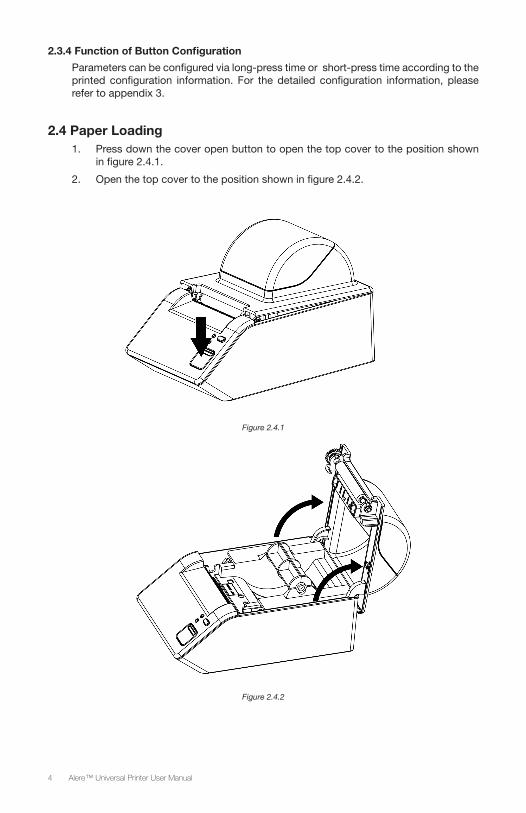
2.4 Paper Loading1. Press down the cover open button to open the top cover to the position shown
in figure 2.4.1.
2. Open the top cover to the position shown in figure 2.4.2.
Figure 2.4.1
Figure 2.4.2
5Alere™ Universal Printer User Manual
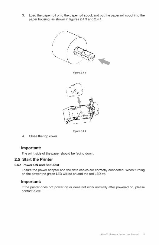
3. Load the paper roll onto the paper roll spool, and put the paper roll spool into the paper housing, as shown in figures 2.4.3 and 2.4.4.
Figure 2.4.3
Figure 2.4.4
4. Close the top cover.
Important:The print side of the paper should be facing down.
2.5 Start the Printer2.5.1 Power ON and Self-Test
Ensure the power adapter and the data cables are correctly connected. When turning on the power the green LED will be on and the red LED off.
Important:If the printer does not power on or does not work normally after powered on, please contact Alere.
6 Alere™ Universal Printer User Manual
2.5.2 Print Self-Test Page
1. Ensure the printer’s power source is connected and the paper roll with spool is loaded into the paper housing.
2. Ensure the green LED is off and the printer is powered off.
• Press and hold the feed button.
• While holding the feed button, turn on the power switch.
• When the printer starts feeding, release the feed button.
Press the feed button twice and hold (at least 1s) and the printer will print out the configuration information (for a sample print out, refer to appendix 2) and the prompt information (“Press and Release FEED to continue SELF-TEST printing” and “Press and Hold FEED to configure the printer”), and then it will enter into pause and waiting status with the red LED flashing.
3. Pressing down the feed button for a short time, the printer will print out character test page, and the self-test page printing is completed. If the feed button is pressed and held down, the printer will print out the interface with the title of “MAIN MENU”.
2.5.3 Label Verification
Manual Verification
1. Power off the printer.
2. Install the labels or print paper.
3. Press down the feed button while turning on the power switch. After the printer starts feeding the paper, release the feed button, waiting for it to finish the printing of the main menu.
4. Press down the feed button three times, and then hold the feed button down (for at least 1 second). The printer will feed the paper and start the label verification.
• After finishing the verification, the printer enters into standby status; if the mark cannot be found, the printer will distinguish it to be continuous paper.
Important:Manual verification of the labels is needed under each of the following situations:
• Install and use of the printer for the first time.
• Re-installation of the printer after being disconnected.
• The sensor is used for the first time after cleaning.
• The label cannot be effectively recognized during print.
• The operation environment is changed.
Important:• Once the verification of labels is completed, the printer is ready.
• After the above steps and sensor cleaning, if the printer fails the label verification, please contact Alere.
7Alere™ Universal Printer User Manual
3. Printer Adjustment3.1 Adjustment of Parameters3.1.1 Adjustment and Adjustment Range
Adjustment object Setting range Remark
Print darkness 00—90Set the print darkness to a lower grade as long as the print quality is acceptable. This will extend the print head’s durability.
Darkness difference of label paper and continuous paper
20—40Set the darkness of label paper to be higher than that of continuous paper. Default value is 30.
Table 3.1.1
4. Routine MaintenanceClean the print head, roller and sensor according to the following steps.
4.1 Cleaning the Print Head If the following cases occur, the print head should be cleaned:
• Printout is not clear.
• Paper feeds and retracts with excessive noise.
• Debris on the print head.
The following steps are for print head cleaning:
1. Turn off the power and open the top cover.
2. Wait for the print head to cool down completely.
3. Wipe off dust or particles on the surface of the print head with a soft cotton cloth dampened with 70% isopropyl alcohol. (It should not be dripping.)
4. Wait for 5 to 10 minutes until the alcohol evaporates completely. Press down the print head module and close the top cover.
Caution:Do not touch the print head during printing and just after operation. It is a thermal element and can reach a high temperature. Contact with the print head can cause a minor burn.
Important:Do not touch the print head. It is an ESD-sensitive device. Contact with the print head may cause damage.
8 Alere™ Universal Printer User Manual
4.2 Cleaning the Sensor Cover The sensor cover should be cleaned when the following occur:
• During printing, the printer LED flashes the out of paper pattern, when paper is installed.
• The printer does not alarm the paper end LED pattern when there is no paper left.
• The printer does not identify labels correctly.
The following steps are for paper end sensor cover cleaning:
1. Turn off the printer power and open the top cover.
2. Wipe off dust or particles on the dustproof cover surface of the paper end sensor with soft cotton cloth damped with 70% isopropyl alcohol. (It should not be dripping.)
3. Wait for 5 to 10 minutes until the alcohol evaporates completely, press down the print head module and close the top cover.
4.3 Cleaning the Print RollerIf the following cases occur, the roller should be cleaned:
• Printout is not clear.
• Paper feeds and retracts with excessive noise.
• Debris on the print roller.
The following steps are for print roller cleaning:
1. Turn off the power and open the top cover.
2. Wait for the print roller to cool down completely.
3. Wipe off dust or particles on the surface of the print roller with a soft cotton cloth dampened with 70% isopropyl alcohol. (It should not be dripping.)
4. Wait for 5 to 10 minutes until the alcohol evaporates completely, press down the print head module and close the top cover.
Caution:• Before starting routine maintenance of the printer, make sure the power is
turned off.
• Do not touch the surface of the print head with hands or metal.
Important: • Do not use forceps; this will prevent the print head, print roller and sensors
from being scratched.
• Do not use organic solvent like gasoline, acetone etc.
• Please wait for the alcohol to evaporate completely before printing.
9Alere™ Universal Printer User Manual
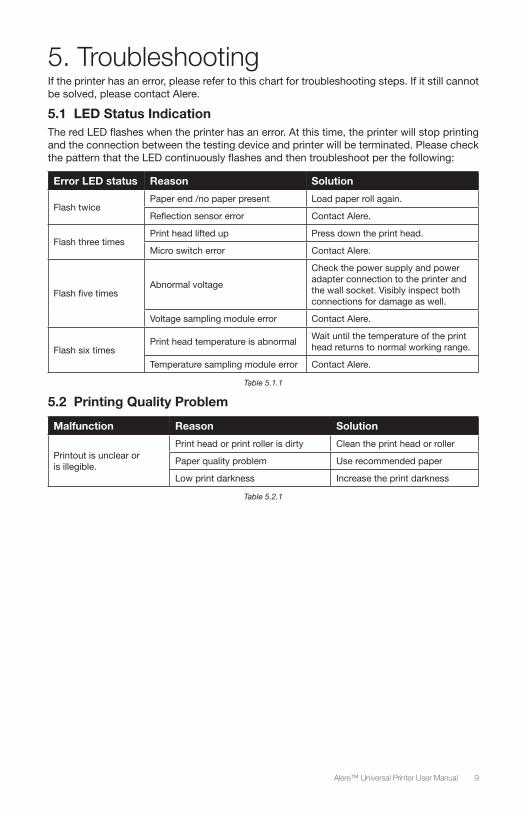
5. TroubleshootingIf the printer has an error, please refer to this chart for troubleshooting steps. If it still cannot be solved, please contact Alere.
5.1 LED Status IndicationThe red LED flashes when the printer has an error. At this time, the printer will stop printing and the connection between the testing device and printer will be terminated. Please check the pattern that the LED continuously flashes and then troubleshoot per the following:
Error LED status Reason Solution
Flash twicePaper end /no paper present Load paper roll again.
Reflection sensor error Contact Alere.
Flash three timesPrint head lifted up Press down the print head.
Micro switch error Contact Alere.
Flash five timesAbnormal voltage
Check the power supply and power adapter connection to the printer and the wall socket. Visibly inspect both connections for damage as well.
Voltage sampling module error Contact Alere.
Flash six timesPrint head temperature is abnormal
Wait until the temperature of the print head returns to normal working range.
Temperature sampling module error Contact Alere.
Table 5.1.1
5.2 Printing Quality Problem
Malfunction Reason Solution
Printout is unclear or is illegible.
Print head or print roller is dirty Clean the print head or roller
Paper quality problem Use recommended paper
Low print darkness Increase the print darkness
Table 5.2.1
10 Alere™ Universal Printer User Manual
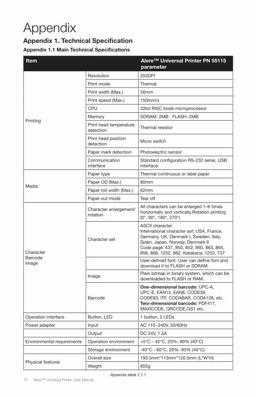
AppendixAppendix 1. Technical SpecificationAppendix 1.1 Main Technical Specifications
Item Alere™ Universal Printer PN 55115 parameter
Printing
Resolution 203DPI
Print mode Thermal
Print width (Max.) 56mm
Print speed (Max.) 150mm/s
CPU 32bit RISC kiosk microprocessor
Memory SDRAM: 2MB FLASH: 2MB
Print head temperature detection
Thermal resistor
Print head position detection
Micro switch
Paper mark detection Photoelectric sensor
Communication interface
Standard configuration RS-232 serial, USB interface
Media
Paper type Thermal continuous or label paper
Paper OD (Max.) 80mm
Paper roll width (Max.) 62mm
Paper out mode Tear off
CharacterBarcodeImage
Character enlargement/rotation
All characters can be enlarged 1–6 times horizontally and vertically.Rotation printing (0°, 90°, 180°, 270°)
Character set
ASCII characterInternational character set: USA, France, Germany, UK, Denmark I, Sweden, Italy, Spain, Japan, Norway, Denmark IICode page: 437, 850, 852, 860, 863, 865, 858, 866, 1252, 862, Katakana, 1253, 737
User-defined font: User can define font and download it to FLASH or SDRAM.
ImagePlain bitmap in binary system, which can be downloaded to FLASH or RAM.
Barcode
One-dimensional barcode: UPC-A, UPC-E, EAN13, EAN8, CODE39, CODE93, ITF, CODABAR, CODA128, etc.Two-dimensional barcode: PDF417, MAXICODE, QRCODE,GS1 etc.
Operation interface Button, LED 1 button, 2 LEDs
Power adapter Input AC 110~240V, 50/60Hz
Output DC 24V, 1.5A
Environmental requirements Operation environment +5°C - 45°C, 20%~90% (40°C)
Storage environment -40°C - 60°C, 20%~93% (40°C)
Physical featuresOverall size 193.5mm*113mm*120.5mm (L*W*H)
Weight 655g
Appendix table 1.1.1
11Alere™ Universal Printer User Manual
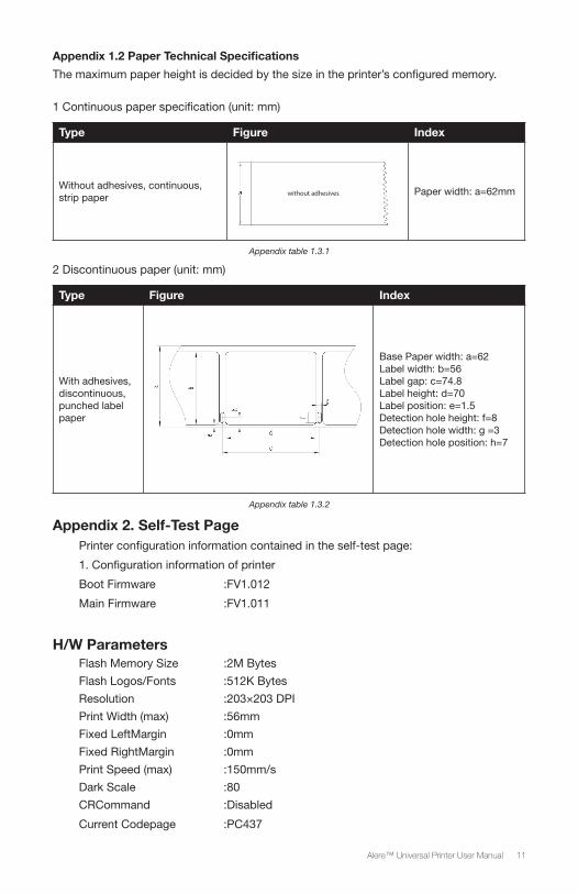
Appendix 1.2 Paper Technical Specifications
The maximum paper height is decided by the size in the printer’s configured memory.
1 Continuous paper specification (unit: mm)
Type Figure Index
Without adhesives, continuous, strip paper without adhesives Paper width: a=62mm
Appendix table 1.3.1
2 Discontinuous paper (unit: mm)
Type Figure Index
With adhesives, discontinuous, punched label paper
Base Paper width: a=62 Label width: b=56 Label gap: c=74.8Label height: d=70 Label position: e=1.5Detection hole height: f=8 Detection hole width: g =3Detection hole position: h=7
Appendix table 1.3.2
Appendix 2. Self-Test PagePrinter configuration information contained in the self-test page:
1. Configuration information of printer
Boot Firmware :FV1.012
Main Firmware :FV1.011
H/W ParametersFlash Memory Size :2M Bytes
Flash Logos/Fonts :512K Bytes
Resolution :203×203 DPI
Print Width (max) :56mm
Fixed LeftMargin :0mm
Fixed RightMargin :0mm
Print Speed (max) :150mm/s
Dark Scale :80
CRCommand :Disabled
Current Codepage :PC437
12 Alere™ Universal Printer User Manual
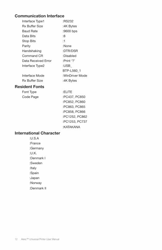
Communication Interface Interface Type1 :RS232
Rx Buffer Size :4K Bytes
Baud Rate :9600 bps
Data Bits :8
Stop Bits :1
Parity :None
Handshaking :DTR/DSR
Command CR :Disabled
Data Received Error :Print ‘?’
Interface Type2 :USB_
BTP-L560_1
Interface Mode :WinDriver Mode
Rx Buffer Size :4K Bytes
Resident FontsFont Type :ELITE
Code Page :PC437, PC850
:PC852, PC860
:PC863, PC865
:PC858, PC866
:PC1252, PC862
:PC1253, PC737
:KATAKANA
International Character :U.S.A
:France
:Germany
:U.K.
:Denmark I
:Sweden
:Italy
:Spain
:Japan
:Norway
:Denmark II
13Alere™ Universal Printer User Manual
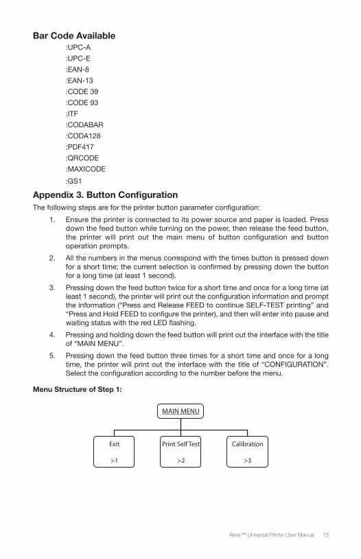
Bar Code Available
:UPC-A
:UPC-E
:EAN-8
:EAN-13
:CODE 39
:CODE 93
:ITF
:CODABAR
:CODA128
:PDF417
:QRCODE
:MAXICODE
:GS1
Appendix 3. Button ConfigurationThe following steps are for the printer button parameter configuration:
1. Ensure the printer is connected to its power source and paper is loaded. Press down the feed button while turning on the power, then release the feed button, the printer will print out the main menu of button configuration and button operation prompts.
2. All the numbers in the menus correspond with the times button is pressed down for a short time; the current selection is confirmed by pressing down the button for a long time (at least 1 second).
3. Pressing down the feed button twice for a short time and once for a long time (at least 1 second), the printer will print out the configuration information and prompt the information (“Press and Release FEED to continue SELF-TEST printing” and “Press and Hold FEED to configure the printer), and then will enter into pause and waiting status with the red LED flashing.
4. Pressing and holding down the feed button will print out the interface with the title of “MAIN MENU”.
5. Pressing down the feed button three times for a short time and once for a long time, the printer will print out the interface with the title of “CONFIGURATION”. Select the configuration according to the number before the menu.
Menu Structure of Step 1:
MAIN MENU
Exit
>1
Print Self Test
>2
Calibration
>3
14 Alere™ Universal Printer User Manual
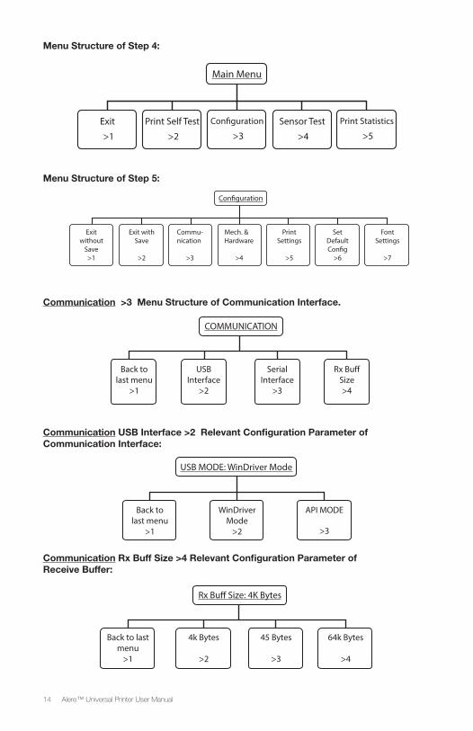
Menu Structure of Step 4:
Main Menu
Exit
>1
Con�guration
>3Sensor Test
>4
Print Self Test
>2
Print Statistics
>5
Menu Structure of Step 5:
Con�guration
Exit without
Save >1
Exit with Save
>2
Commu-nication
>3
Mech. & Hardware
>4
Print Settings
>5
Set Default Con�g
>6
Font Settings
>7
Communication >3 Menu Structure of Communication Interface.
COMMUNICATION
USB Interface
>2
Back to last menu
>1
Serial Interface
>3
Rx Bu� Size >4
Communication USB Interface >2 Relevant Configuration Parameter of Communication Interface:
USB MODE: WinDriver Mode
Back to last menu
>1
WinDriver Mode
>2
API MODE
>3
Communication Rx Buff Size >4 Relevant Configuration Parameter of Receive Buffer:
Rx Bu� Size: 4K Bytes
Back to last menu
>1
4k Bytes
>2
45 Bytes
>3
64k Bytes
>4
15Alere™ Universal Printer User Manual
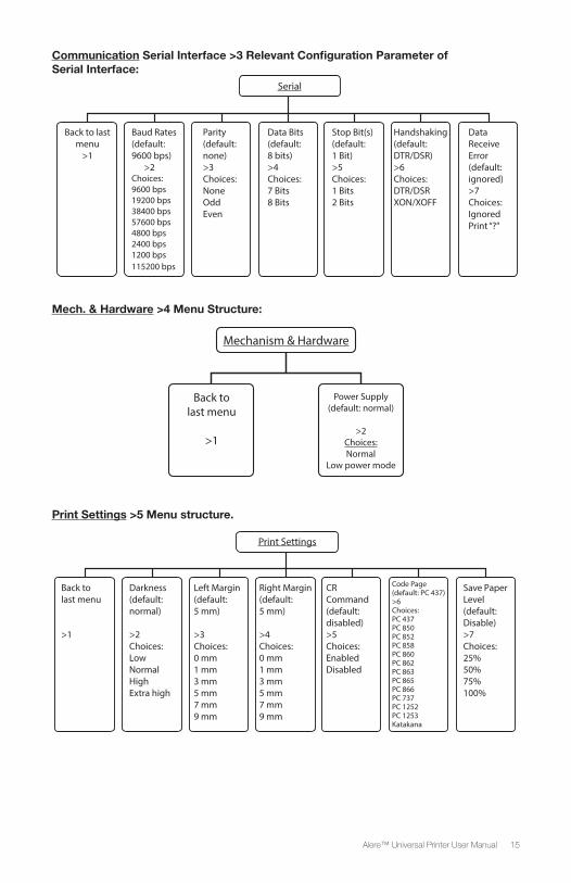
Communication Serial Interface >3 Relevant Configuration Parameter of Serial Interface:
Serial
Back to last menu
>1
Baud Rates (default: 9600 bps) >2Choices: 9600 bps 19200 bps 38400 bps 57600 bps 4800 bps 2400 bps 1200 bps 115200 bps
Parity (default: none)>3Choices: None Odd Even
Data Bits (default: 8 bits)>4Choices: 7 Bits8 Bits
Stop Bit(s) (default: 1 Bit)>5Choices: 1 Bits2 Bits
Handshaking (default: DTR/DSR)>6Choices: DTR/DSRXON/XOFF
Data Receive Error (default: ignored)>7Choices: Ignored Print “?”
Mech. & Hardware >4 Menu Structure:
Mechanism & Hardware
Back to last menu
>1
Power Supply (default: normal)
>2
Choices:Normal
Low power mode
Print Settings >5 Menu structure.
Print Settings
Back to last menu
>1
Darkness (default: normal)
>2Choices: LowNormalHighExtra high
Left Margin (default: 5 mm)
>3Choices:0 mm1 mm3 mm5 mm7 mm9 mm
Right Margin(default: 5 mm)
>4Choices:0 mm1 mm3 mm5 mm7 mm9 mm
CRCommand(default:disabled)>5Choices:EnabledDisabled
Code Page(default: PC 437)>6Choices: PC 437PC 850PC 852PC 858PC 860PC 862PC 863PC 865PC 866PC 737PC 1252PC 1253Katakana
Save Paper Level(default: Disable)>7Choices:25%50%75%100%
16 Alere™ Universal Printer User Manual
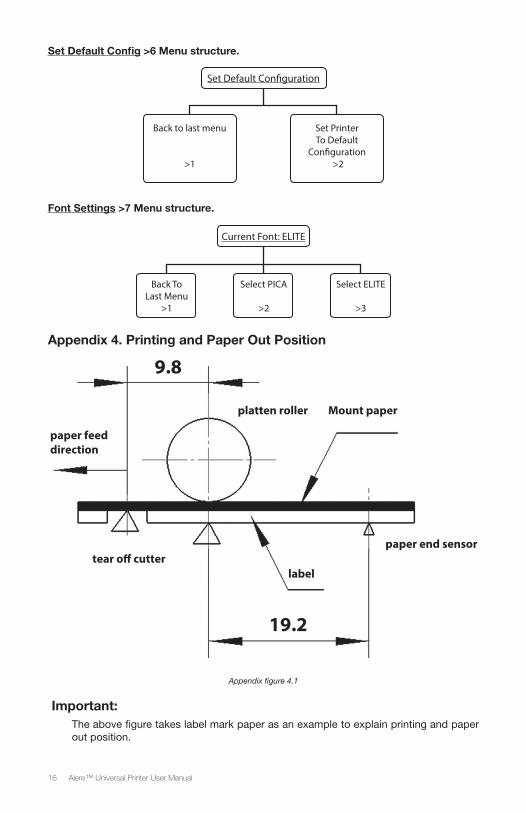
Set Default Config >6 Menu structure.
Set Default Con�guration
Back to last menu
>1
Set PrinterTo Default
Con�guration >2
Font Settings >7 Menu structure.
Current Font: ELITE
Back To Last Menu
>1
Select PICA
>2
Select ELITE
>3
Appendix 4. Printing and Paper Out Position
paper feed direction
tear o� cutter
platten roller Mount paper
paper end sensor
label
9.8
19.2
Appendix figure 4.1
Important:The above figure takes label mark paper as an example to explain printing and paper out position.
17Alere™ Universal Printer User Manual
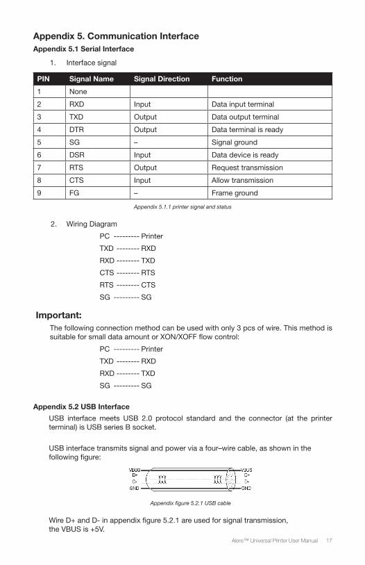
Appendix 5. Communication InterfaceAppendix 5.1 Serial Interface
1. Interface signal
PIN Signal Name Signal Direction Function
1 None
2 RXD Input Data input terminal
3 TXD Output Data output terminal
4 DTR Output Data terminal is ready
5 SG – Signal ground
6 DSR Input Data device is ready
7 RTS Output Request transmission
8 CTS Input Allow transmission
9 FG – Frame ground
Appendix 5.1.1 printer signal and status
2. Wiring Diagram
PC --------- Printer
TXD -------- RXD
RXD -------- TXD
CTS -------- RTS
RTS -------- CTS
SG --------- SG
Important:The following connection method can be used with only 3 pcs of wire. This method is suitable for small data amount or XON/XOFF flow control:
PC --------- Printer
TXD -------- RXD
RXD -------- TXD
SG --------- SG
Appendix 5.2 USB Interface
USB interface meets USB 2.0 protocol standard and the connector (at the printer terminal) is USB series B socket.
USB interface transmits signal and power via a four–wire cable, as shown in the following figure:
Appendix figure 5.2.1 USB cable
Wire D+ and D- in appendix figure 5.2.1 are used for signal transmission, the VBUS is +5V.
18 Alere™ Universal Printer User Manual
Appendix 6 Guidance and Manufacturer’s Declaration – Electromagnetic Emissions
• The device needs special EMC precautions and must be installed and started according to the EMC information supplied in this manual.
• Portable and mobile RF communications equipment could affect the device. For example mobile phones can affect the device. Avoid placing a mobile phone in direct proximity to the device.
• Important: The use of accessories, other than those recommended by the manufacturer, may result in stronger emissions or reduce the immunity of the device.
• Important: The device should not be used beside or stacked on top of any other equipment. If you must use it side by side or on top of another system, you should check that the device works properly in the chosen configuration.
• Meeting the emissions levels shown in the first table is considered to be essential performance of the device.
GUIDANCE AND MANUFACTURER’S DECLARATION –ELECTROMAGNETIC EMISSIONS
The device is intended for use in the electromagnetic environment specified below. The customer or user of the device should assure that it is used in such an environment
Emissions test Compliance Electromagnetic environment - guide
RF emissions CISPR 11
Group 1 The device uses RF energy only for its internal function. Therefore, its RF emissions are very low and are not likely to cause any interference in nearby electronic equipment.
RF emissions CISPR 11
Class A The device is suitable for use in all establishments other than domestic and those directly connected to the public low-voltage power supply network that supplies buildings used for domestic purposes.
Suitable for use in all establishments, specifically in commercial, industrial settings.
Harmonic emissions IEC 61000-3-2
Class A
Voltage fluctuations/ emission oscillations IEC 61000-3-3
Complies
19Alere™ Universal Printer User Manual
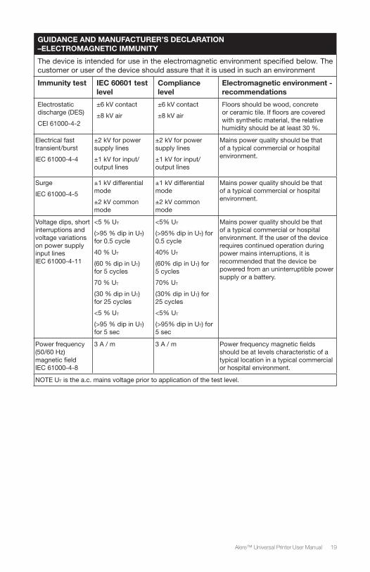
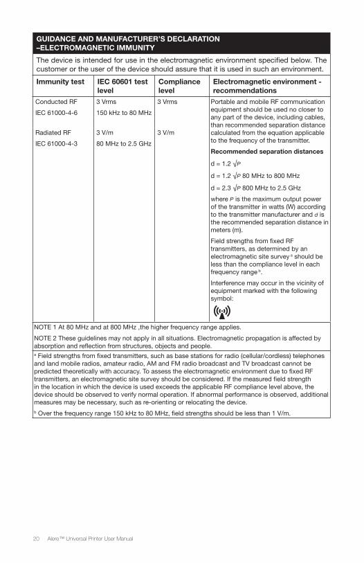
GUIDANCE AND MANUFACTURER’S DECLARATION –ELECTROMAGNETIC IMMUNITY
The device is intended for use in the electromagnetic environment specified below. The customer or user of the device should assure that it is used in such an environment
Immunity test IEC 60601 test level
Compliance level
Electromagnetic environment - recommendations
Electrostatic discharge (DES)
CEI 61000-4-2
±6 kV contact
±8 kV air
±6 kV contact
±8 kV air
Floors should be wood, concrete or ceramic tile. If floors are covered with synthetic material, the relative humidity should be at least 30 %.
Electrical fast transient/burst
IEC 61000-4-4
±2 kV for power supply lines
±1 kV for input/output lines
±2 kV for power supply lines
±1 kV for input/output lines
Mains power quality should be that of a typical commercial or hospital environment.
Surge
IEC 61000-4-5
±1 kV differential mode
±2 kV common mode
±1 kV differential mode
±2 kV common mode
Mains power quality should be that of a typical commercial or hospital environment.
Voltage dips, short interruptions and voltage variations on power supply input lines IEC 61000-4-11
<5 % UT
(>95 % dip in UT) for 0.5 cycle
40 % UT
(60 % dip in UT) for 5 cycles
70 % UT
(30 % dip in UT) for 25 cycles
<5 % UT
(>95 % dip in UT) for 5 sec
<5% UT
(>95% dip in UT) for 0.5 cycle
40% UT
(60% dip in UT) for 5 cycles
70% UT
(30% dip in UT) for 25 cycles
<5% UT
(>95% dip in UT) for 5 sec
Mains power quality should be that of a typical commercial or hospital environment. If the user of the device requires continued operation during power mains interruptions, it is recommended that the device be powered from an uninterruptible power supply or a battery.
Power frequency (50/60 Hz) magnetic field IEC 61000-4-8
3 A / m 3 A / m Power frequency magnetic fields should be at levels characteristic of a typical location in a typical commercial or hospital environment.
NOTE UT is the a.c. mains voltage prior to application of the test level.
20 Alere™ Universal Printer User Manual
GUIDANCE AND MANUFACTURER’S DECLARATION –ELECTROMAGNETIC IMMUNITY
The device is intended for use in the electromagnetic environment specified below. The customer or the user of the device should assure that it is used in such an environment.
Immunity test IEC 60601 test level
Compliance level
Electromagnetic environment - recommendations
Conducted RF
IEC 61000-4-6
3 Vrms
150 kHz to 80 MHz
3 Vrms Portable and mobile RF communication equipment should be used no closer to any part of the device, including cables, than recommended separation distance calculated from the equation applicable to the frequency of the transmitter.
Recommended separation distances
d = 1.2 √P
d = 1.2 √P 80 MHz to 800 MHz
d = 2.3 √P 800 MHz to 2.5 GHz
where P is the maximum output power of the transmitter in watts (W) according to the transmitter manufacturer and d is the recommended separation distance in meters (m).
Field strengths from fixed RF transmitters, as determined by an electromagnetic site survey a should be less than the compliance level in each frequency range b.
Interference may occur in the vicinity of equipment marked with the following symbol:
Radiated RF
IEC 61000-4-3
3 V/m
80 MHz to 2.5 GHz
3 V/m
NOTE 1 At 80 MHz and at 800 MHz ,the higher frequency range applies.
NOTE 2 These guidelines may not apply in all situations. Electromagnetic propagation is affected by absorption and reflection from structures, objects and people.a Field strengths from fixed transmitters, such as base stations for radio (cellular/cordless) telephones and land mobile radios, amateur radio, AM and FM radio broadcast and TV broadcast cannot be predicted theoretically with accuracy. To assess the electromagnetic environment due to fixed RF transmitters, an electromagnetic site survey should be considered. If the measured field strength in the location in which the device is used exceeds the applicable RF compliance level above, the device should be observed to verify normal operation. If abnormal performance is observed, additional measures may be necessary, such as re-orienting or relocating the device.b Over the frequency range 150 kHz to 80 MHz, field strengths should be less than 1 V/m.
21Alere™ Universal Printer User Manual
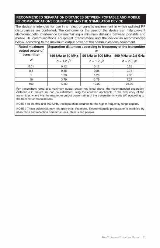
RECOMMENDED SEPARATION DISTANCES BETWEEN PORTABLE AND MOBILE RF COMMUNICATIONS EQUIPMENT AND THE STIMULATOR DEVICE
The device is intended for use in an electromagnetic environment in which radiated RF disturbances are controlled. The customer or the user of the device can help prevent electromagnetic interference by maintaining a minimum distance between portable and mobile RF communications equipment (transmitters) and the device as recommended below, according to the maximum output power of the communications equipment.
Rated maximum output power of
transmitter
W
Separation distances according to frequency of the transmitter m
150 kHz to 80 MHz
d = 1.2 √P
80 kHz to 800 MHz
d = 1.2 √P
800 MHz to 2.5 GHz
d = 2.3 √P
0.01 0.12 0.12 0.23
0.1 0.38 0.38 0.73
1 1.20 1.20 2.30
10 3.79 3.79 7.27
100 12.00 12.00 23.00
For transmitters rated at a maximum output power not listed above, the recommended separation distance d in meters (m) can be estimated using the equation applicable to the frequency of the transmitter, where P is the maximum output power rating of the transmitter in watts (W) according to the transmitter manufacturer.
NOTE 1 At 80 MHz and 800 MHz, the separation distance for the higher frequency range applies.
NOTE 2 These guidelines may not apply in all situations. Electromagnetic propagation is modified by absorption and reflection from structures, objects and people.
22 Alere™ Universal Printer User Manual
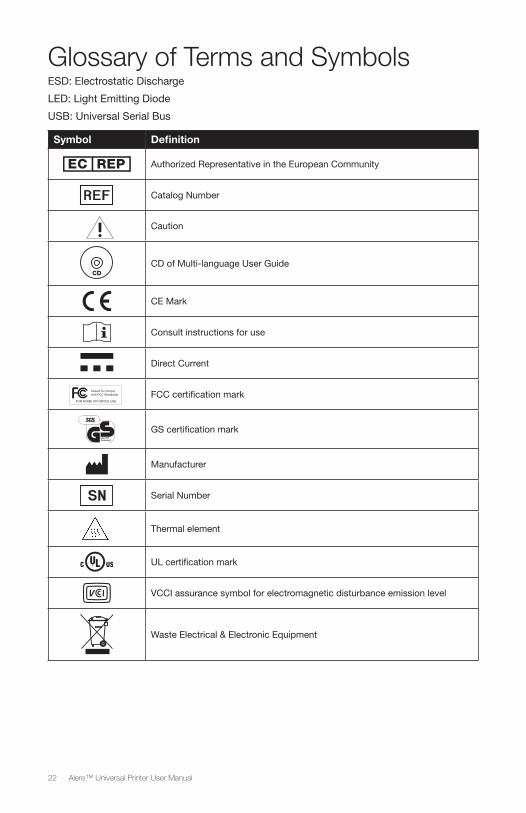
Glossary of Terms and SymbolsESD: Electrostatic Discharge
LED: Light Emitting Diode
USB: Universal Serial Bus
Symbol Definition
Authorized Representative in the European Community
Catalog Number
Caution
CDCD of Multi-language User Guide
CE Mark
Consult instructions for use
Direct Current
Tested To Complywith FCC Standards
FOR HOME OR OFFICE USE
FCC certification mark
GS certification mark
Manufacturer
Serial Number
Thermal element
UL certification mark
VCCI assurance symbol for electromagnetic disturbance emission level
Waste Electrical & Electronic Equipment
23Alere™ Universal Printer User Manual
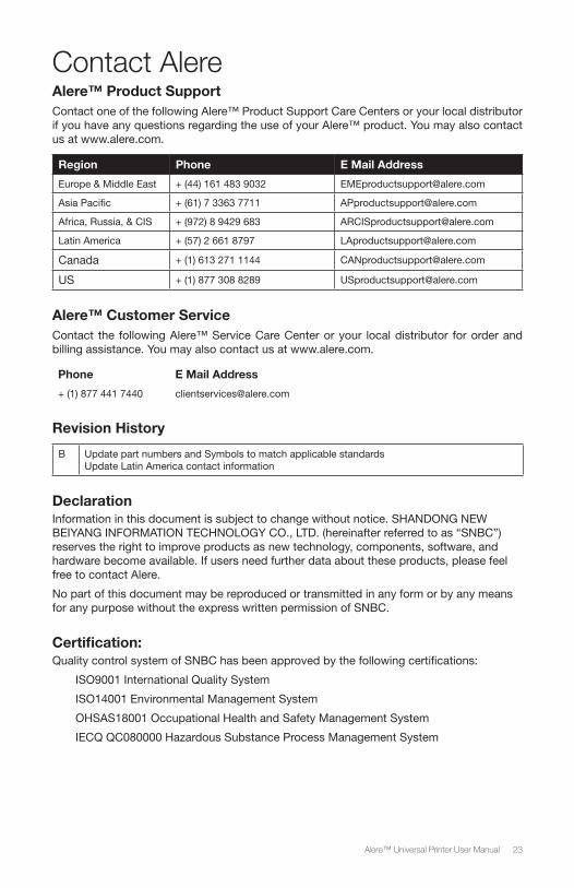
Contact Alere Alere™ Product Support Contact one of the following Alere™ Product Support Care Centers or your local distributor if you have any questions regarding the use of your Alere™ product. You may also contact us at www.alere.com.
Region Phone E Mail Address
Europe & Middle East + (44) 161 483 9032 [email protected]
Asia Pacific + (61) 7 3363 7711 [email protected]
Africa, Russia, & CIS + (972) 8 9429 683 [email protected]
Latin America + (57) 2 661 8797 [email protected]
Canada + (1) 613 271 1144 [email protected]
US + (1) 877 308 8289 [email protected]
Alere™ Customer ServiceContact the following Alere™ Service Care Center or your local distributor for order and billing assistance. You may also contact us at www.alere.com.
Phone E Mail Address
+ (1) 877 441 7440 [email protected]
Revision History
B Update part numbers and Symbols to match applicable standardsUpdate Latin America contact information
DeclarationInformation in this document is subject to change without notice. SHANDONG NEW BEIYANG INFORMATION TECHNOLOGY CO., LTD. (hereinafter referred to as “SNBC”) reserves the right to improve products as new technology, components, software, and hardware become available. If users need further data about these products, please feel free to contact Alere.
No part of this document may be reproduced or transmitted in any form or by any means for any purpose without the express written permission of SNBC.
Certification:Quality control system of SNBC has been approved by the following certifications:
ISO9001 International Quality System
ISO14001 Environmental Management System
OHSAS18001 Occupational Health and Safety Management System
IECQ QC080000 Hazardous Substance Process Management System


The Alere Logo and Alere are trademarks of the Alere group of companies.© 2017 Alere. All rights reserved.PN: 55115-4 Rev. B 2017/10
Imported by: SNBC Europe B.V. Meerheide 115, 5521 DX Eersel The Netherlands
Distributed by:Alere San Diego, Inc.9975 Summers Ridge Rd.San Diego, CA 92121www.alere.com
Manufactured by:Shandong New Beiyang Information Technology Co., Ltd.No.169 Huoju Road, High-Tech Zone Weihai, Shandong