Embed Size (px)
Citation preview

AkMITSUBISHI HEAVY INDUSTRIES, LTD.
16-5, KONAN 2-CHOME, MINATO-KU
TOKYO, JAPAN
April 23, 2013
Document Control DeskU.S. Nuclear Regulatory CommissionWashington, DC 20555-0001
Attention: Mr. Jeffrey A. CioccoDocket No. 52-021
MHI Ref: UAP-HF-13098
Subject: MHI's Revised Response to US-APWR DCD RAI No. 861-6062 Revision 3(SRP 15.06.05) Question No. 15.6.5-100
References: 1) Request for Additional Information No. 861-6062 Revision 3 - Loss ofCoolant Accidents Resulting From Spectrum of Postulated Piping BreaksWithin the Reactor Coolant Pressure Boundary", dated October 31, 2011(ML1 13060529).
2) UAP-HF-11448, 2 nd MHI's Responses to US-APWR DCD RAI No.861-6062Revision 3 (SRP 15.06.05), dated December 22, 2011 (ML11362A466).
With this letter, Mitsubishi Heavy Industries, Ltd. ("MHI") transmits to the U.S. NuclearRegulatory Commission ("NRC") the document entitled "MHI's Revised Response to US-APWRDCD RAI No. 861-6062 Revision 3, Question No. 15.6.5-100".
Enclosed is the revised response to Question 15.06.05-100, which includes further explanationregarding the impact of US-APWR core debris blockage on the post-LOCA long-term coolingevaluation.
As indicated in the enclosed materials, this document contains information that MHI considersproprietary, and therefore should be withheld from public disclosure pursuant to 10 C.F.R.§ 2.390 (a)(4) as trade secrets and commercial or financial information which is privileged orconfidential. A non-proprietary version of the document is also being submitted in this package(Enclosure 3). In the non-proprietary version, the proprietary information, bracketed in theproprietary version, is replaced by the designation "[ ]".
This letter includes a copy of the proprietary version of the RAI response (Enclosure 2), a copyof the non-proprietary version of the RAI response (Enclosure 3), and the Affidavit of YoshikiOgata (Enclosure 1) which identifies the reasons MHI respectfully requests that all materialdesignated as "Proprietary" in Enclosure 2 be withheld from disclosure pursuant to 10 C.F.R.§ 2.390 (a)(4).
Please contact Mr. Joseph Tapia, General Manager of Licensing Department, MitsubishiNuclear Energy Systems, Inc. if the NRC has questions concerning any aspect of this submittal.His contact information is provided below.

Sincerely,
Yoshiki Ogata,Executive Vice PresidentMitsubishi Nuclear Energy Systems, Inc.On behalf of Mitsubishi Heavy Industries, LTD.
Enclosures:
1. Affidavit of Ogata Yoshiki
2. MHI's Revised Response to US-APWR DCD RAI No. 861-6062 Revision 3, Question No.15.6.5-100 (proprietary)
3. MHI's Revised Response to US-APWR DCD RAI No. 861-6062 Revision 3, Question No.15.6.5-100 (non-proprietary)
CC: J. A. CioccoJ. Tapia
Contact InformationJoseph Tapia, General Manager of Licensing DepartmentMitsubishi Nuclear Energy Systems, Inc.1001 19th Street North, Suite 710Arlington, VA 22209E-mail: joseph [email protected]: (703) 908 - 8055
ENCLOSURE 1Docket No. 52-021
MHI Ref: UAP-HF-13098
MITSUBISHI HEAVY INDUSTRIES, LTD.
AFFIDAVIT
I, Yoshiki Ogata, state as follows:
1. I am Executive Vice President of Mitsubishi Nuclear Energy Systems, Inc., and have beendelegated the function of reviewing MITSUBISHI HEAVY INDUSTRIES, LTD's ("MHI")US-APWR documentation to determine whether it contains information that should bewithheld from public disclosure pursuant to 10 C.F.R. § 2.390 (a)(4) as trade secrets andcommercial or financial information which is privileged or confidential.
2. In accordance with my responsibilities, I have reviewed the enclosed document entitled"MHI's Revised Response to US-APWR DCD RAI No. 861-6062 Revision 3, Question No.15.6.5-100," and have determined that portions of the document contain proprietaryinformation that should be withheld from public disclosure. Those pages containingproprietary information are identified with the label "Proprietary" on the top of the pageand the proprietary information has been bracketed with an open and closed bracket asshown here "[ ]". The first page of the document indicates that all information identifiedas "Proprietary" should be withheld from public disclosure pursuant to 10 C.F.R. § 2.390(a)(4).
3. The information identified as proprietary in the enclosed document has in the past been,and will continue to be, held in confidence by MHI and its disclosure outside the companyis limited to regulatory bodies, customers and potential customers, and their agents,suppliers, and licensees, and others with a legitimate need for the information, and isalways subject to suitable measures to protect it from unauthorized use or disclosure.
4. The basis for holding the referenced information confidential is that it describes the uniquedesign information of the safety analysis, developed by MHI and not used in the exactform by any of MHI's competitors. This information was developed at significant cost toMHI, since it required the performance of Research and Development and detailed designfor its software and hardware extending over several years.
5. The referenced information is being furnished to the Nuclear Regulatory Commission("NRC") in confidence and solely for the purpose of information to the NRC staff.
6. The referenced information is not available in public sources and could not be gatheredreadily from other publicly available information. Other than through the provisions inparagraph 3 above, MHI knows of no way the information could be lawfully acquired byorganizations or individuals outside of MHI.
7. Public disclosure of the referenced information would assist competitors of MHI in theirdesign of new nuclear power plants without the costs or risks associated with the designof the subject systems. Therefore, disclosure of the information contained in thereferenced document would have the following negative impacts on the competitiveposition of MHI in the U.S. nuclear plant market.

A. Loss of competitive advantage due to the costs associated with development ofthe US-APWR Safety Analysis. Providing public access to such informationpermits competitors to duplicate or mimic the safety analysis information withoutincurring the associated costs.
B. Loss of competitive advantage of the US-APWR created by benefits of enhancedUS-APWR Safety Analysis development costs associated with the SafetyAnalysis.
I declare under penalty of perjury that the foregoing affidavit and the matters stated thereinare true and correct to the best of my knowledge, information, and belief.
Executed on this 2 3 rd day of April, 2013.
Yoshiki Ogata,Executive Vice PresidentMitsubishi Nuclear Energy Systems, Inc.
Docket No. 52-021MHI Ref: UAP-HF-13098
ENCLOSURE 3
UAP-HF-13098Docket No. 52-021
MHI's Revised Response to US-APWR DCD RAI No. 861-6062Revision 3, Question No. 15.6.5-100
April 2013
(Non-Proprietary)

RESPONSE TO REQUEST FOR ADDITIONAL INFORMATION
04/23/2013
US-APWR Design Certification
Mitsubishi Heavy Industries
Docket No. 52-021
RAI NO.: NO. 861-6062 REVISION 3
SRP SECTION: 15.06.05 - LOSS OF COOLANT ACCIDENTS RESULTING FROMSPECTRUM OF POSTULATED PIPING BREAKS WITHIN THEREACTOR COOLANT PRESSURE BOUNDARY
APPLICATION SECTION: 15.6.5
DATE OF RAI ISSUE: 10/31/2011
QUESTION NO.: 15.6.05-100
Follow-up to RAI 5352, Question 15.6.5-89:Provide an updated response to RAI 719-5352, Question 15.6.5-89 that takes intoconsideration relevant and conforming findings related to US-APWR core debris blockage thatalso accounts for any experimental test results to assess the US-APWR core blockage.Currently, such additional information is planned to be included in Revision 2 ofMUAP-080013-P, "US-APWR Sump Strainer Downstream Effects," scheduled for release byMHI on August 31, 2011.
ANSWER:
After the quenching of the core at the end of the reflood phase, continued operation of theECCS supplies borated water from the RWSP to remove decay heat and to keep the coresubcritical. Theborated water from the RWSP is initially injected through the DVI lines. Insuch a situation, sump strainer bypass debris is also carried by the ECCS water, which has thepotential to adversely affect the boric acid concentration behavior in the reactor vessel.
Chapter 4 of the technical report MUAP-08013-P Revision 2, "US-APWR Sump StrainerDownstream Effects" (Ref-(1)), describes in-vessel downstream effects of bypass debris onlong-term core cooling and the boric acid mixing volume. In this response to the RAI,important effects which can impact post-LOCA long-term cooling evaluation are discussed.
Trapping debris on grid spacer or cladding surface
In the case where bypass debris physically or chemically adheres to grid spacer or claddingsurfaces, the debris acts as an insulator and impedes heat transfer from the fuel rods to coolantin the core. It results in a small decrease in heat transfer, but the rate of heat transfer recoversin a short time period since fuel rod and cladding temperature increases slightly. Thetemperature differential between the cladding and the coolant also increases, which
15.6.05-100.1

compensates for the degradation of the heat transfer coefficient. The small increase incladding and fuel rod temperature does not directly affect the accumulation of boric acid in themixing volume. The accumulation of boric acid in the mixing volume is controlled by the coredecay heat level, which is not affected by debris in the ECC. Therefore, it is concluded thatdebris trapping or plate out should not significantly affect the post-LOCA long term coolingevaluation.
Effect of suspended and settled sump debris on mixing volume
The suspended and settled debris transported into the vessel may have some impact on themixing volume. The bypass debris settled or suspended in the coolant replaces water volumein the mixing volume. The amount of bypass debris that may exist in the mixing volume isdescribed and estimated in Ref-(1) Appendix-D.
The lower plenum in the US-APWR has a large volume of more than one thousand cubic feet,thus the liquid volume potentially replaced by debris is a small fraction of the mixing volumeassumed in the post-LOCA long term cooling evaluation. Because the fraction of the mixingvolume displaced by debris is so small the debris effect on the mixing process and the boricacid contribution will be negligible.
Effect of core inlet blockage on mixing volumeThe possibility of the core inlet blockage due to debris is discussed in Section 4.4.1 (2) ofRef-(1), which states that significant core inlet blockage will not take place in practice. Asshown in the previous response to RAI 719-5352 Question 15.6.5-89(Ref- 2), the mixing flow rateand velocity needed to maintain the boric acid concentration in the lower plenum is quite low.
MHI has carried out a core inlet blockage test to supplement the technical information in Ref-(1).The results of this additional test are reported in a technical report (Ref-(4)). According to theconservative test results, the debris that reaches the core may inhibit the core inlet flow as wellas the mixing flow between the core and the lower plenum.
To confirm the flow pattern in and around the core under assumed core inlet blockageconditions a WCOBRA/TRAC analysis was performed. Attachment-1 shows the calculationconditions and provides the detailed results. From these analyses, it is concluded thehigh-concentration boric-acid water begins to flow from the upper plenum to the lower plenumthough the neutron reflector (NR) region before the core fluid reaches the boric-acidprecipitation concentration criterion, even though core inlet blockage may impede the mixingbetween the core and the lower plenum during the early portion of the post-LOCA long-termcooling period. The rate of this NR downward flow is sufficient to assure good mixing andmitigate the rate of additional concentration increase. The evaluation in Section 4 ofAttachment-1 indicates the boric acid concentration becomes the same as the DCD referencecase before the core fluid reaches the boric acid precipitation concentration criterion.
The results in Attachment-1 support MHI's conclusion that current assumption of including halfof the lower plenum as a part of mixing volume is still valid even under core inlet blockageconditions.
Effect of two-phase core mixture level
In the post-LOCA long-term cooling evaluation, it is assumed that the core two-phase mixture
15.6.05-100.2

level will not fall below the bottom of the hot leg before the hot leg switch-over and that themixing volume includes the upper plenum, below the hot leg. When the core inlet blockage bydebris is considered, the two-phase mixture level is not expected to fall below the bottom of thehot leg elevation for the following reasons:
* As discussed above, the potential flow blockage would occur mainly at the fuel assemblybottom nozzle. The region below the fuel inlet nozzle elevation is filled with water at orbelow saturation temperature and core inlet flow velocity drops to a very low level early inthe post-LOCA long-term cooling period.
* The evaluation of core flow driven by the RV pressure differential is discussed in theresponse to DCD RAI 861-6062, Question 15.06.05-94 (Ref-(3)). In that RAI response,it is shown that the estimated core flow rate driven by the RV pressure differential ismuch larger than the core makeup flow rate, which means that there is significant marginregarding available driving head to produce core flow.
* In the response to RAI 861-6062 Question 15.6.05-95 (Ref-(3)) it was shown that thevoid distribution and mixture level in the core and upper plenum is determined primarilyby the core power level and axial power profile. Since these parameters do not changeif debris is present the mixture level should not change.
Effect of blockaqe on alternate core coolant flow path
Sump debris may accumulate sufficiently to block some of the core bypass flow paths that areexpected to dilute the boric acid concentration in the mixing volume (core). The following flowpaths are considered as potential core bypass paths.
* Upper head spray nozzle through control guide tube* Control-rod guide tubes, core thimble tubes* Neutron reflector (NR)* Hot leg nozzle gaps
The NR region is considered as an alternate flow path in terms of the mixing flow between thecore and the lower plenum (Attachment-I). It is considered that the upward flow though theNR is continued during the early period of post-LOCA long-term cooling, so there is a possibilitythat part of the debris flows into the NR region. However, the entering debris will not be caughtin NR region since the narrowest diameter in the NR is much larger than the strainer flow areadiameter. None of the flow paths listed above, other the NR region, are modeled or credited inthe post-LOCA long term cooling evaluation. Therefore, the sump debris in these core bypasspaths has no impact on the post-LOCA long term cooling evaluation.
Conclusion
The above discussion show that the sump bypass debris may affect the post-LOCA long termcooling evaluation only in terms of core inlet clogging, but its impact on core cooling is limited.As a result, the core region mixing volume used in the US-APWR long term cooling analyses isstill valid and there is no need to change the hot leg switch over time (4 hour).
References:1. MUAP-08013-P(R2), "US-APWR Sump Strainer Downstream Effects", August 20112. MHI Letter No. UAP-HF-11139, "MHI's Response to US-APWR DCD RAI No. 719-5352
Revision 0 (15.06.05)", dated May 18,20113. MHI Letter No. UAP-HF-11416, ,,1 st MHI's Responses to US-APWR DCD RAI No. 861-6062
Revision 3 (SRP 15.06.05)", dated December 2, 20114. MUAP-110022-P(RO), "US-APWR Additional Core Inlet Blockage Test", October 2011
15.6.05-100.3
Impact on DCD
There is no impact on the DCD.
Impact on R-COLA
There is no impact on the R-COLA.
Impact on S-COLA
There is no impact on the S-COLA.
Impact on PRA
There is no impact on the PRA.
Impact on Technical/Topical Report
There is no impact on a Technical/Topical Report.
15.6.05-100.4

Attachment-1 Core and Lower Plenum Mixing Phenomena under Core Inlet BlockageConditions
1. Introduction
Regarding the post-LOCA long-term evaluation for the US-APWR, the mixing flow between thecore and the lower plenum occurs due to the effects of solution density differences.Additionally, it is assumed that half of the lower plenum volume is included as part of the "mixingvolume" where boric acid potentially precipitates, which is equivalent to the entire lower plenumvolume being subjected to half of the core boric acid concentration (Ref-(1)).
In the case that the core inlet blockage is formed by debris, the flow communication betweenthe core and the lower plenum is impacted. According the Ref-(2), most of the debris adheresthe core fuel assembly bottom nozzles and chokes the flow area creating a large flowresistance. As a result, the mixing flow through the core fuel assembly bottom nozzles due tothe solution density inversion decreases.
Regarding the mixing behavior in and around the core region, another mixing mechanism, otherthan solution density inversion, exists. The continuous liquid and droplet which are entrainedby the vapor phase flows out from the core. Some of the entrained droplets go to the externalloop(s) along with the vapor flow, whereas the remaining water returns to the core.Additionally, part of the returned water flows downward through the core outer area or neutronreflector (NR) region. In this case the condensed boric acid water is carried to the core bottomand top of the lower plenum. In practice, there is a possibility that the aforementionedmechanism is the dominant mixing flow rather than the mixing flow by the solution densityinversion.
MHI assumes that condensed boric acid water generated in the core is carried to under thelower core support plate through the core outer channel and NR channel even under core inletblockage conditions. To confirm the aforementioned flow pattern, MHI performed theWCOBRA/TRAC (M1.0) code based large break LOCA long-term core cooling analysis todemonstrate that the NR is an alternate flow path between the core and lower plenum and toconfirm the flow direction and flow rate of the NR region.
15.6.05-100.5

Upper Plenum
(a)Mixing flow COREdue to core pool
boiling
(b)Mixing flow -oi-cdwtrfo hdue to solution '""°re dueto Bcnvetion
density inversion
(a) NR downward flow appears during the post-LOCA long-term period
(b) Mixing flow due to unstable density difference has been shown by the BACCHUS testresults.
Fig. 1-1 Expected Mixing Flow in the US-APWR
15.6.05-100.6

2. Estimation of Pressure Loss Coefficient Due to the Core Inlet Blockage
The pressure loss coefficient was estimated by the following procedure in order to simulate theimpact of the fluid resistance due to the core inlet blockage by debris.
Technical report MUAP-110022-P (Ref-(2)) describes the core inlet blockage test performed byMHI and the test results. This test utilizes a single mock-up assembly to represent theUS-APWR core. From the viewpoint of the post-LOCA long-term cooling evaluation, the coreboric acid precipitation becomes a problem only in the case of a cold leg break LOCA, thus, thepressure loss coefficient was estimated from the results of the cold break LOCA condition testseries described in Ref-(2). Considering the difference between the Ref-(2) test boundarycondition and the WCOBRA/TRAC (M1.0) code calculation condition in terms of the core inletflow, the pressure loss coefficient applied to the core inlet was calculated as follows.
Fig.2-1 shows the time history of the flow rate at the core inlet in the case of no core inletblockage. The calculated core inlet flow rate becomes larger than the flow rate which wasapplied to the core inlet blockage test of Ref-(2) since the applied flow rate for the test wasderived only from the boil-off rate generated by the core decay heat. As shown in this figure,the core inlet flow oscillates during the early period of the transient; it is considered that theaverage core inlet flow rate is [ ]. Then the representative core inlet flow rate was setto [ ], and the pressure loss coefficient corresponding to the flow rate was estimatedfrom the test results described in Ref-(2).
The four CIB test cases for the cold leg break conditions, which were varied as discussed inRef-(2) are the applicable test cases. The test results of case CL4-h were used since theseresults indicated the highest pressure loss. The test condition and test results of CL4-h are asfollows.
Test Condition (CL4-h)Volumetric Flow Rate 13.3 liters/min (100%)
[ ][ ]
[ ]System Pressure Atmospheric pressureFluid Temperature Room temperature
15.6.05-100.7

Test Results(CL4-h)
The CL4-h test result indicates that the pressure loss is proportional to the volumetric flow rate.Therefore, the pressure loss coefficient to be applied to the WCOBRA/TRAC (M1.0) codeanalysis is estimated by extrapolating from the [
] of the aforementioned test results. The correlating equation obtained from the testdata is as follows.
[ ] (Fig. 2-2)where;
AP: pressure loss (psi), Q: Flow Rate (converted to entire core flow rate) (ft3/sec)
The pressure loss in case of [ ] of core inlet flow is[ ] (psi)
The pressure loss at the core inlet is simulated as a form loss coefficient in the WCOBRA/TRAC(M1.0) code analysis. The form loss coefficient (Kin) is calculated as follows.
2 x 32.17 x Ain2 x 144Ki = AP~nPin X•in
where;o jn= 59.25 Ibm/ft3
Ain: = [:= [
A p: = [
]
]
Liquid density (assumed as saturation liquid densityunder atmospheric pressure)
Core Inlet Flow AreaCore Inlet Flow RatePressure Loss
As a result, the form loss coefficient applied to the WCOBRA/TRAC (M1.0) code analysis isobtained.
Kn= [ ] (Core inlet flow area (Ain) basis)
15.6.05-100.8

Fig.2-1 Core Inlet Flow Rate (No Core Inlet Blockage Condition)
Fig.2-2 Correlation of Pressure Loss at the Core Inlet under Debris Blockage Condition for theUS-APWR
15.6.05-100.9

3. WCOBRA/TRAC Analysis Results (Core Inlet Blockage Condition)
Post large break LOCA long-term core cooling analysis using the WCOBRA/TRAC (M1.0) codewas performed based on the DCD Rev. 3 reference case with the addition of simulated coreinlet blockage. Only the core inlet form loss coefficient described in the previous section waschanged from the base case.
The core inlet blockage occurs 850 seconds after the LOCA occurrence. In this analysis, theform loss coefficient is applied starting at 850 seconds after LOCA and linearly increased to themaximum value over the next [ ] seconds. Fig.3-1 shows the time history of the integral ofthe NR inlet flow rate. The core inlet flow is restricted since a large pressure loss is developedand the water head in the NR region increases to balance the core inlet head loss.
According to the analysis, the NR inlet flows [
] After the core inlet blockage begins at 850 seconds, the flow inthe NR region [
] The downward flow in the NR region carries the condensed boric acid waterfrom the core to the lower plenum as stated in the Section 1 and it is expected that the boricacid in the core (mixing volume) decreases after that time.
15.6.05-100.10

Fig.3-1 Integral of Mass Flow Rate at the NR Inlet (Bottom)
15.6.05-100.11

4. Boric-Acid Concentration Transient in the Core (Mixing Volume) Under Core Inlet BlockageConditions
Assuming the reduction of the mixing communication between the core and the lower plenumcaused by the core inlet blockage due to debris, a boric-acid concentration transient calculationwas performed which excludes the entire lower plenum volume as a part of the mixing volume.The evaluation model is same as the DCD reference case, which is provided in Ref-(3).Fig. 4-1 shows the time history of boric acid concentration for the case the entire lower plenumvolume is excluded, compared with the DCD reference case. In this case, the volume ofmixing region significantly decreases compared with DCD reference case assumption, thus theboric-acid concentration rate rapidly increases. This case indicates that the boric-acidconcentration exceeds the concentration criterion (29.27 wt.%) at about 6,800 seconds (1.9hours).
On the other hand, as described in the previous section, the WCOBRA/TRAC (M1.0) codeanalysis indicates that the NR region flow turns downward around [ ] seconds. Therefore,it is expected that the boric-acid concentration in the core (mixing volume) decreases since thehigh-condensed boric-acid water generated in the core (mixing volume) flows out to the top ofthe lower plenum (under the lower core support plate) via the NR region.
Fig. 4-2 illustrates the rough estimation of NR average downward flow rate after [ Iseconds. According to the WCOBRA/TRAC (M1.0) code analysis results, a total liquid mass of[ ] Ibm flows approximately linearly out from the NR region to the lower plenum between[ ] and 14,400 seconds (4 hours). Since the NR is almost filled with the liquid during thetransient, the downward flow rate at the top of the NR region is same as at the bottom.
As shown in Fig. 4-2, the average flow rate through the NR region after [ ] seconds (WNR)
is as follows.WNR= [ ] Ibm/sec
Assuming the constant downward flow rate through the NR region after [ ] seconds, theboric acid concentration in the core (mixing volume) is evaluated by the following calculation.Fig. 4-3 shows the evaluation model of post-LOCA long term cooling considering the constantNR downward flow under the core inlet blockage condition. In this evaluation, the lowerplenum is independently modeled from the core mixing volume.
In this evaluation, the fundamental calculation method is basically the same as DCD referencecase described in DCD Section 15.6.5.3.1.3.
(Assumptions)* The following parameters are input as boundary conditions.
- Core evaporation rate (from the DCD reference case)- Liquid phase volume above the core (from the DCD reference case)- RWSP boric acid concentration (from the DCD reference case)- NR downward flow rate (from the WCOBRA/TRAC (M1.0) code calculation)
# The core inlet flow is a summation of "core makeup flow (including core evaporation flow)"and "upward flow from the lower plenum".
The core inlet flow rate estimated by the WCOBRA/TRAC (M1.0) code is muchlarger than this flow rate because the WCOBRA/TRAC (M1.0) code flow rateincludes the entrained liquid droplet flow which flows out to the external loop(s)through the upper plenum. This outflow is conservatively excluded from the boricacid mass flow calculation since the entrained droplet contains boric-acid whichcould reduce boric acid concentration of the core (mixing volume).
15.6.05-100.12
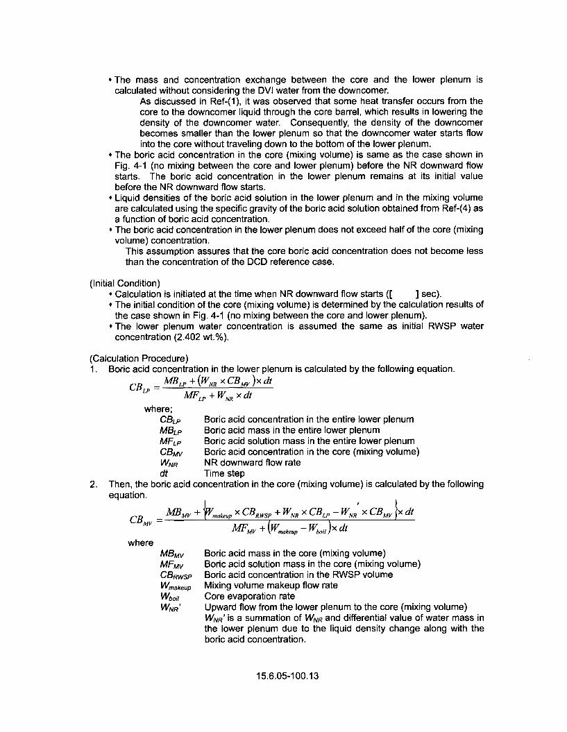
* The mass and concentration exchange between the core and the lower plenum iscalculated without considering the DVI water from the downcomer.
As discussed in Ref-(1), it was observed that some heat transfer occurs from thecore to the downcomer liquid through the core barrel, which results in lowering thedensity of the downcomer water. Consequently, the density of the downcomerbecomes smaller than the lower plenum so that the downcomer water starts flowinto the core without traveling down to the bottom of the lower plenum.
* The boric acid concentration in the core (mixing volume) is same as the case shown inFig. 4-1 (no mixing between the core and lower plenum) before the NR downward flowstarts. The boric acid concentration in the lower plenum remains at its initial valuebefore the NR downward flow starts.
* Liquid densities of the boric acid solution in the lower plenum and in the mixing volumeare calculated using the specific gravity of the boric acid solution obtained from Ref-(4) asa function of boric acid concentration.
# The boric acid concentration in the lower plenum does not exceed half of the core (mixingvolume) concentration.
This assumption assures that the core boric acid concentration does not become lessthan the concentration of the DCD reference case.
(Initial Condition)* Calculation is initiated at the time when NR downward flow starts ([ ] sec).* The initial condition of the core (mixing volume) is determined by the calculation results of
the case shown in Fig. 4-1 (no mixing between the core and lower plenum).* The lower plenum water concentration is assumed the same as initial RWSP water
concentration (2.402 wt.%).
(Calculation Procedure)1. Boric acid concentration in the lower plenum is calculated by the following equation.
CBP = M/RLP + (WNR X CBMV)x dt
FLP + WNR x dt
where;CBLP Boric acid concentration in the entire lower plenumMBLP Boric acid mass in the entire lower plenumMFLp Boric acid solution mass in the entire lower plenumCBMv Boric acid concentration in the core (mixing volume)WNR NR downward flow ratedt Time step
2. Then, the boric acid concentration in the core (mixing volume) is calculated by the followingequation.
MBv +' •.xCBws +WRX CBLP--WN xCBv ixdtAM MV +akxp X RWSP -NR - R r
CBW MFm + (W..k~,p - WboiI )X citwhere
MBMv Boric acid mass in the core (mixing volume)MFMv Boric acid solution mass in the core (mixing volume)CBRwsp Boric acid concentration in the RWSP volumeWmakeup Mixing volume makeup flow rateWb~il Core evaporation rateWNR' Upward flow from the lower plenum to the core (mixing volume)
WNR' is a summation of WNR and differential value of water mass inthe lower plenum due to the liquid density change along with theboric acid concentration.
15.6.05-100.13

Fig. 4-4 shows the calculated time-history of the core (mixing volume) boric acid concentrationconsidering the constant NR downward flow and the core Inlet blockage. Before the NRdownward flow starts at [ ] seconds, the time-history of boric acid concentration isassumed to be the same as the no-mixing case shown in Fig. 4-1. After the NR downwardflow starts from [ ] seconds, the increase of the core boric acid concentration is mitigated.The boric acid concentration in the lower plenum reaches half of the core (mixing volume) boricacid concentration at [ ] seconds, which means that the boric acid concentrationbecomes consistent with the concentration of the DCD reference case.
15.6.05-100.14

----- DCD Reference Case-Lower Plenum Volume
30
25
0• 20
r-150U
< 15
0
I 510
0 2,500 5,000 7,500 10,000 12,500 15,000Time (sec)
Fig.4-1 Boric Acid Concentration Transient
Fig.4-2 Explanation of the Estimation of NR Average Downward Flow Rate
15.6.05-100.15
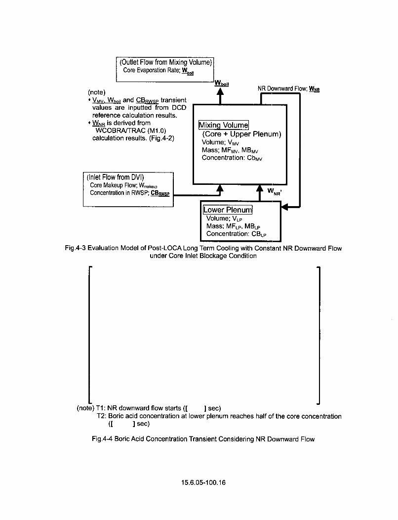
(Outlet Flow from Mixing Volume)Core Evaporation Rate; WWI I AI
(note)* VMV. Wh and C_ wsP transient
values are inputted from DCDreference calculation results.
* WNR is derived fromWCOBRA/TRAC (M1.0)
calculation results. (Fig.4-2)
"Vaboilt NR Downward Flow; WNR
m
IMixing Volumel(Core + Upper Plenum)Volume; VMVMass; MFMv, MBMvConcentration: CbMv
(Inlet Flow from DVI)Core Makeup Flow; Wmakeup
Concentration in RWSP; CBRwsP • -t W NR,
I
ILower PlenumlVolume; VLPMass; MFLP, MBLP
Concentration: CBLP
4-
Fig.4-3 Evaluation Model of Post-LOCA Long Term Cooling with Constant NR Downward Flowunder Core Inlet Blockage Condition
(note) TI: NR downward flow starts ([ ] sec)T2: Boric acid concentration at lower plenum reaches half of the core concentration
(I ] sec)
Fig.4-4 Boric Acid Concentration Transient Considering NR Downward Flow
15.6.05-100.16

5. Conclusion
The WCOBRA/TRAC (M1.0) code calculation result shown in Section 3 indicates that thedownward flow from the upper plenum to the lower plenum support plate through the NR regionis formed continuously, except during the early portion of the post-LOCA long-term coolingperiod. It is expected that the downward flow assures good mixing between the core and thelower plenum, and mitigates the rate of additional concentration increase in the core. Theevaluation of boric acid concentration transient considering NR downward flow is provided inSection 4, which demonstrates the rate of downward flow is sufficient and the boric acidconcentration can become the same as DCD reference case before the core fluid reaches theboric acid precipitation concentration criterion.
In conclusion, it is considered that the current assumption of including the half of the lowerplenum as a part of the mixing volume is still valid because the downward flow through the NRregion remains sufficient during the post-LOCA long-term cooling period to promote adequatemixing even in the case of core inlet blockage due to debris.
6. References
Ref-(1) MHI Letter No. UAP-HF-11139, "MHI's Response to US-APWR DCD RAI 719-5352Revision 0 (15.06.05)" (May 18, 2011) RAI Question 15.6.5-89
Ref-(2) MUAP-1 10022-P(R0), "US-APWR Additional Core Inlet Blockage Test", October 2011Ref-(3) MHI Letter No. UAP-HF-09384, "MHI's response to US-APWR DCD RAI No. 352-2369
Revision 1" (July 2009) RAI Question 15.6.5-44 Appendix-BRef-(4) "Boric Acid Application Guidelines for Intergranular Corrosion Inhibition," EPRI, Palo
Alto, CA: 1987, NP-5558, page 2-27
15.6.05-100.17