Embed Size (px)
Citation preview
AISI S230-07 w/2-08-C
AISI STANDARD
Commentary on Standard for
Cold-Formed Steel Framing -
Prescriptive Method for One
and Two Family Dwellings
2007 Edit ion with Supplement 2
Revis ion of : A ISI/COFS/PM-2006
Endorsed by Steel Framing Alliance
ii Commentary on AISI S230-07 w/S2-08
DISCLAIMER
The material contained herein has been developed by the American Iron and Steel Institute (AISI) Committee on Framing Standards. The Committee has made a diligent effort to present accurate, reliable, and useful information on cold-formed steel framing design and installation. The Committee acknowledges and is grateful for the contributions of the numerous researchers, engineers, and others who have contributed to the body of knowledge on the subject. Specific references are included in this Commentary.
With anticipated improvements in understanding of the behavior of cold-formed steel framing and the continuing development of new technology, this material will become dated. It is anticipated that AISI will publish updates of this material as new information becomes available, but this cannot be guaranteed.
The materials set forth herein are for general purposes only. They are not a substitute for competent professional advice. Application of this information to a specific project should be reviewed by a design professional. Indeed, in many jurisdictions, such review is required by law. Anyone making use of the information set forth herein does so at their own risk and assumes any and all liability arising therefrom.
The user is advised to check the availability of specific framing material in the region in which the dwelling is being constructed.
1st Printing – February 2009
Copyright American Iron and Steel Institute 2008
Commentary on the Prescriptive Method for One and Two Family Dwellings iii
PREFACE
The American Iron and Steel Institute (AISI) Committee on Framing Standards (COFS) has developed this Commentary on the Standard for Cold-Formed Steel Framing - Prescriptive Method for One and Two Family Dwellings [Commentary] to provide the background, supplemental information, engineering assumptions and methods, and detailed calculations for the provisions of the AISI 230 Prescriptive Method (AISI S230-07 w/S2-08).
The loads, load combinations, and other design parameters used to develop the provisions in the AISI S230 were based on the International Residential Code (ICC, 2006b), the International Building Code (ICC, 2006a) (where no provisions are included in the IRC) and ASCE 7 (ASCE, 2005).
Commentary is provided only for those sections of the AISI S230 where background or supplemental information is of benefit to the user. Sections thought to need no explanation are left blank.
This document is divided into two sections. Section 1, Commentary, contains the background, supplemental information and engineering assumptions. Section 2, Design Examples, contains detailed calculations that demonstrate how the values in the AISI S230 were derived.
Terms within the body of this Commentary that are shown in italics indicate that the italicized word is a defined term by the AISI S230 or by the General Provisions (AISI S200-07).
The Committee acknowledges and is grateful for the contributions of the numerous engineers, researchers, producers and others who have contributed to the body of knowledge on the subjects. The Committee wishes to also express their appreciation for the support and encouragement of the Steel Framing Alliance.
iv Commentary on AISI S230-07 w/S2-08
AISI COMMITTEE ON FRAMING STANDARDS
Richard Haws, Chairman NUCONSTEEL Steve Fox, Vice Chairman Canadian Sheet Steel Building Institute Jay Larson, Secretary American Iron and Steel Institute Don Allen Steel Stud Manufacturers Association Bill Babich ITW Building Components Group John Butts John F. Butts & Associates Brad Cameron Keymark Engineering Richard Chisholm Lacerte Builders Nader Elhajj FrameCAD Solutions Jeff Ellis Simpson Strong-Tie Ray Frobosilo Super Stud Building Products Michael Gardner Gypsum Association Greg Greenlee USP Structural Connectors Jeff Klaiman ADTEK Engineers Roger LaBoube Missouri Institute for Science & Technology John Matsen Matsen Ford Design Associates Kenneth Pagano Scosta Corporation Mike Pellock Aegis Metal Framing Nabil Rahman The Steel Network Greg Ralph Dietrich Industries Harry Ray Allied Studco Gary Rolih Consultant Ben Schafer Johns Hopkins University Fernando Sesma California Expanded Metal Products Sutton Stephens Kansas State University Tom Trestain T.W.J. Trestain Structural Engineering Steven Walker Steven H. Walker, P.Eng. Lei Xu University of Waterloo Rahim Zadeh Marino\Ware
Commentary on the Prescriptive Method for One and Two Family Dwellings v
PRESCRIPTIVE METHOD SUBCOMMITTEE
Steve Fox, Chairman Canadian Sheet Steel Building Institute Jay Larson, Secretary American Iron and Steel Institute Don Allen Steel Stud Manufacturers Association Nader Elhajj FrameCAD Solutions Michael Gardner Gypsum Association Greg Greenlee USP Structural Connectors Richard Layding NUCONSTEEL John Matsen Matsen Ford Design Associates Greg Ralph Dietrich Industries Fernando Sesma California Expanded Metal Products Sutton Stephens Kansas State University Tim Waite Simpson Strong-Tie Lei Xu University of Waterloo Rahim Zadeh Marino\Ware

vi Commentary on AISI S230-07 w/S2-08
This Page Intentionally Left Blank
Commentary on the Prescriptive Method for One and Two Family Dwellings vii
TABLE OF CONTENTS
COMMENTARY ON THE STANDARD FOR COLD-FORMED STEEL FRAMING –
PRESCRIPTIVE METHOD FOR ONE AND TWO FAMILY DWELLINGS DISCLAIMER................................................................................................................................ ii PREFACE..................................................................................................................................... iii AISI COMMITTEE ON FRAMING STANDARDS.......................................................................... iv PRESCRIPTIVE METHODS SUBCOMMITTEE............................................................................. v
PART 1 – COMMENTARY............................................................................................................1 A. GENERAL................................................................................................................................1
A1 Scope ................................................................................................................................................ 1 A1.1 Limits of Applicability ...................................................................................................... 1 A1.2 Limitations in High Seismic and High Wind Areas .................................................... 2
A2 Definitions....................................................................................................................................... 2 A3 Referenced Documents ................................................................................................................. 2 A4 Limitations of Framing Members ............................................................................................... 3
A4.1 General ................................................................................................................................. 3 A4.2 Physical Dimensions.......................................................................................................... 3 A4.3 Material Properties ............................................................................................................ 4 A4.4 Web Holes ........................................................................................................................... 4 A4.5 Hole Reinforcing ................................................................................................................ 5 A4.6 Hole Patching...................................................................................................................... 5
B. CONNECTIONS.......................................................................................................................6 B1 Fastening Requirements ............................................................................................................... 6 B2 Bearing Stiffeners ........................................................................................................................... 6 B3 Clip Angles ..................................................................................................................................... 6 B4 Anchor Bolts ................................................................................................................................... 7
D. FLOOR FRAMING...................................................................................................................8 D1 Floor Construction......................................................................................................................... 8 D2 Floor to Foundation or Structural Wall Connection................................................................ 8 D3 Minimum Floor Joist Sizes ........................................................................................................... 8
D3.1 Floor Cantilevers ................................................................................................................ 9 D4 Bearing Stiffeners ........................................................................................................................... 9 D5 Joist Bracing and Blocking............................................................................................................ 9
D5.1 Joist Top Flange Bracing ................................................................................................... 9 D5.2 Joist Bottom Flange Bracing/Blocking ........................................................................... 9 D5.3 Blocking at Interior Bearing Supports .......................................................................... 10 D5.4 Blocking at Cantilevers ................................................................................................... 10
D6 Splicing .......................................................................................................................................... 10 D7 Framing of Floor Openings........................................................................................................ 10 D8 Floor Trusses................................................................................................................................. 10 D9 Diaphragms .................................................................................................................................. 10
D9.1 Floor Diaphragms in High Seismic and High Wind Areas ...................................... 11
viii Commentary on AISI S230-07 w/S2-08
E. WALL FRAMING.................................................................................................................. 12 E2 Wall to Foundation or Floor Connection................................................................................. 12 E3 Minimum Stud Sizes ................................................................................................................... 12 E4 Stud Bracing.................................................................................................................................. 13 E5 Splicing .......................................................................................................................................... 14 E6 Corner Framing............................................................................................................................ 14 E7 Headers.......................................................................................................................................... 14
E7.1 Box Headers ...................................................................................................................... 14 E7.2 Back-to-Back Headers...................................................................................................... 15 E7.3 L-Headers .......................................................................................................................... 15 E7.4 Jack and King Studs......................................................................................................... 16 E7.5 Head and Sill Track ......................................................................................................... 16
E8 Wall Bracing.................................................................................................................................. 16 E8.1 Strap Bracing (X-brace) ................................................................................................... 17 E8.2 Structural Sheathing ........................................................................................................ 17 E8.3 Structural Sheathing Fastening...................................................................................... 18 E8.4 Hold-down Requirements.............................................................................................. 18
E9 Exterior Wall Covering ............................................................................................................... 18 E11 Braced Walls in High Wind Areas and High Seismic Areas................................................ 18
E11.1 General .............................................................................................................................. 18 E11.2 Braced Wall Lines............................................................................................................ 20 E11.3 Type I (Solid Sheathed) Braced Wall Panels .............................................................. 20 E11.4 Type II (Perforated) Braced Wall Lines....................................................................... 21
E12 Braced Wall Design in High Seismic Areas ............................................................................ 21 E12.2 Braced Wall Anchorage and Chord Stud Requirements ......................................... 21
E13 Braced Wall Design in High Wind Areas................................................................................ 21 E13.3 Connections of Walls in High Wind Areas ................................................................ 21
F. ROOF FRAMING.................................................................................................................. 22 F1 Roof Construction........................................................................................................................ 22 F2 Ceiling Joists ................................................................................................................................. 22
F2.1 Minimum Ceiling Joist Size............................................................................................ 22 F2.2 Ceiling Joist Bearing Stiffeners ...................................................................................... 22 F2.3 Ceiling Joist Bottom Flange Bracing ............................................................................. 22 F2.4 Ceiling Joist Top Flange Bracing ................................................................................... 22 F2.5 Ceiling Joist Splicing........................................................................................................ 22
F3 Roof Rafters................................................................................................................................... 23 F3.1 Minimum Roof Rafter Sizes ........................................................................................... 23 F3.2 Roof Rafter Support Brace .............................................................................................. 23 F3.3 Roof Rafter Splice............................................................................................................. 23 F3.5 Roof Rafter Bottom Flange Bracing............................................................................... 23
F4 Hip Framing ................................................................................................................................. 24 F5 Framing of Openings in Roofs and Ceilings........................................................................... 24 F6 Roof Trusses.................................................................................................................................. 24 F7 Ceiling and Roof Diaphragms................................................................................................... 24
Commentary on the Prescriptive Method for One and Two Family Dwellings ix
PART 2 – DESIGN EXAMPLES................................................................................................. 25 A. INTRODUCTION................................................................................................................... 25
A1 Member Properties ...................................................................................................................... 25 A2 Design Loads ................................................................................................................................ 25
A2.1 Roof Snow Loads.............................................................................................................. 26 A2.2 Wind Loads ....................................................................................................................... 26
A3 Load Combinations ..................................................................................................................... 30 A4 Deflection Limits.......................................................................................................................... 31 A5 Design Checks and Assumptions ............................................................................................. 32
D. FLOOR FRAMING DESIGN EXAMPLES ............................................................................. 37 D1 Floor Joist Design......................................................................................................................... 37
D1.1 Shear Capacity .................................................................................................................. 37 D1.2 Moment Capacity............................................................................................................. 37 D1.3 Deflection Limit................................................................................................................ 37 D1.4 Web Crippling Capacity ................................................................................................. 38 D1.5 Maximum Allowable Joist Span.................................................................................... 38
D2 Header Joist Design..................................................................................................................... 38 D3 Trimmer Joist Design .................................................................................................................. 39 D4 Floor Diaphragm Design............................................................................................................ 40
E. WALL FRAMING DESIGN EXAMPLES ............................................................................... 42 E1 Wall Stud Design ......................................................................................................................... 42
E1.1 Design Assumptions........................................................................................................ 42 E1.2 Design Loads..................................................................................................................... 42 E1.3 Load Combinations.......................................................................................................... 43 E1.4 Member Properties .......................................................................................................... 43 E1.5 Combined Axial and Bending Capacity ...................................................................... 43 E1.6 Deflection Limit................................................................................................................ 45
E2 Box Header Design...................................................................................................................... 45 E2.1 Design Loads..................................................................................................................... 46 E2.2 Load Combinations.......................................................................................................... 46 E2.3 Member Properties .......................................................................................................... 46 E2.4 Bending Capacity ............................................................................................................. 46 E2.5 Deflection Limit................................................................................................................ 46 E2.6 Shear Capacity .................................................................................................................. 47 E2.7 Combined Bending and Web Crippling Capacity ..................................................... 47
E3 Back-to-Back Header Design ..................................................................................................... 49 E3.1 Design Loads..................................................................................................................... 49 E3.2 Load Combinations.......................................................................................................... 49 E3.3 Member Properties .......................................................................................................... 49 E3.4 Bending Capacity ............................................................................................................. 49 E3.5 Deflection Limit................................................................................................................ 49 E3.6 Shear Capacity .................................................................................................................. 49 E3.7 Combined Bending and Web Crippling Capacity ..................................................... 50
E4 Double L-Header Design (Gravity Loading) .......................................................................... 51 E4.1 Design Loads..................................................................................................................... 51 E4.2 Load Combinations.......................................................................................................... 51 E4.3 Member Properties .......................................................................................................... 51 E4.4 Bending Capacity ............................................................................................................. 51
x Commentary on AISI S230-07 w/S2-08
E5 Double L-Header Design (Uplift Loading Case 1)................................................................. 51 E5.1 Design Loads..................................................................................................................... 52 E5.2 Load Combinations:......................................................................................................... 52 E5.3 Member Properties .......................................................................................................... 52 E5.4 Bending Capacity ............................................................................................................. 52
E6 Double L-Header Design (Uplift Loading Case 2)................................................................. 53 E6.1 Design Loads..................................................................................................................... 53 E6.2 Load Combinations.......................................................................................................... 54 E6.3 Member Properties .......................................................................................................... 54 E6.4 Bending Capacity ............................................................................................................. 54
E7 Head Track Design ...................................................................................................................... 54 E7.1 Design Loads and Assumptions.................................................................................... 55
E9 Shear Wall Design (One Story Building) ................................................................................. 55 E9.1 Design Loads..................................................................................................................... 55 E9.2 Required Sheathing ......................................................................................................... 56
E10 Shear Wall Design (Two Story Building) ................................................................................ 57 E10.1 Design Loads.................................................................................................................... 57 E10.2 Required Sheathing (First Floor Walls)....................................................................... 58
E11 Shear Wall Design (High Seismic Area) .................................................................................. 58 E11.1 Design Assumptions....................................................................................................... 58 E11.2 Design Loads.................................................................................................................... 58 E11.3 Required Sheathing (Side Walls).................................................................................. 62 E11.4 Hold Downs and Multiple Stud Posts (Side Walls).................................................. 62 E11.5 Required Sheathing (End Walls) .................................................................................. 63 E11.6 Hold Downs and Multiple Stud Posts (End Walls) .................................................. 64 E11.7 Continuous Strap for Drag Force ................................................................................. 65 E11.8 Stabilizing Clip at Eave Block ....................................................................................... 66 E11.9 Connection of Shear Wall to Floor Diaphragm to Shear Wall Below.................... 67
E12 Shear Wall Design (High Wind Area)...................................................................................... 67 E12.1 Design Assumptions....................................................................................................... 67 E12.2 Length of Shear Panel (Side Walls).............................................................................. 70 E12.3 Length of Shear Panel (End Walls) .............................................................................. 70 E12.4 Braced Wall Hold Down Anchorage ........................................................................... 72
F. ROOF FRAMING DESIGN EXAMPLES ............................................................................... 73 F1 Ceiling Joist Design ..................................................................................................................... 73
F1.1 Design Assumptions........................................................................................................ 73 F1.2 Design Loads..................................................................................................................... 73 F1.3 Load Combinations.......................................................................................................... 73 F1.4 Member Properties .......................................................................................................... 73 F1.5 Bending Capacity ............................................................................................................. 73 F1.6 Shear Capacity .................................................................................................................. 73 F1.7 Deflection Limit................................................................................................................ 74
F2 Rafter Design ................................................................................................................................ 74 F2.1 Design Assumptions........................................................................................................ 74 F2.2 Design Methodology ....................................................................................................... 74 F2.3 Design Loads..................................................................................................................... 75 F2.4 Load Combinations.......................................................................................................... 77 F2.5 Member Properties .......................................................................................................... 77
Commentary on the Prescriptive Method for One and Two Family Dwellings xi
F2.6 Bending Capacity ............................................................................................................. 77 F2.7 Shear Capacity .................................................................................................................. 77 F2.8 Deflection Limit................................................................................................................ 77
F3 Ridge Member Shear Connection ............................................................................................. 78 F4 Ceiling Joist to Rafter Connection............................................................................................. 79 F5 Roof Diaphragm Design (First Example) ................................................................................ 81 F6 Roof Diaphragm Design (Second Example) ........................................................................... 81 F7 Hip Member Design.................................................................................................................... 82
F7.1 Design Assumptions........................................................................................................ 82 F7.2 Design Loads:.................................................................................................................... 82 F7.3 Load Combinations.......................................................................................................... 84 F7.4 Material and Section Properties..................................................................................... 84 F7.5 Bending Check.................................................................................................................. 85 F7.6 Shear Check....................................................................................................................... 85 F7.7 Deflection Check .............................................................................................................. 85
F8 Hip Member Support Column above Ceiling ........................................................................ 86 F8.1 Design Assumptions........................................................................................................ 86 F8.2 Design Loads..................................................................................................................... 86 F8.3 Load Combinations.......................................................................................................... 87 F8.4 Material Properties .......................................................................................................... 88 F8.5 Axial Compression........................................................................................................... 88 F8.6 Axial Tension .................................................................................................................... 88
F9 Roof Rafter or Truss to Wall Connection................................................................................. 88 F10 Ridge Tension Strap Connection Requirement ...................................................................... 89 F11 Ridge Tension Strap Design....................................................................................................... 91
REFERENCES ........................................................................................................................... 92 APPENDIX A METRIC CONVERSION................................................................................... 94

xii Commentary on AISI S230-07 w/S2-08
This Page Intentionally Left Blank
Commentary on the Prescriptive Method for One and Two Family Dwellings 1
PART 1 – COMMENTARY
ON THE STANDARD FOR COLD-FORMED STEEL FRAMING –
PRESCRIPTIVE METHOD FOR ONE- AND TWO-FAMILY DWELLINGS
A. GENERAL
A1 Scope
AISI S230 consists of prescriptive requirements for cold-formed steel floor, wall, and roof framing to be used in the construction of one- and two-family dwellings, townhouses, and other attached and detached single-family dwellings not more than three stories in height using repetitive in-line framing practices.
A1.1 Limits of Applicability
AISI S230 is not applicable to all possible conditions of use and is subject to the applicability limits set forth in Section A1.1 and A1.2. The applicability limits are necessary to define reasonable boundaries to the conditions that must be considered in developing prescriptive construction requirements. The applicability limits should be carefully understood as they define important constraints on the use of AISI S230.
The applicability limits strike a reasonable balance between engineering theory, available test data, and proven field practices for typical residential construction applications. The applicability limits are intended to prevent misapplication while addressing a reasonably large percentage of new housing conditions. Special consideration is directed toward the following items related to the applicability limits.
Building Geometry: The provisions in AISI S230 apply to detached one- and two-family dwellings, townhouses, and other attached single-family dwellings not more than three stories in height. Its application to homes with complex architectural configurations is subject to careful interpretation by the user and therefore, engineering design support may be required. The most common building widths (or depths) range from 24 feet to 40 feet (7.3 to 12.2 m), with axially load bearing wall heights up to 10 feet (3.1 m). The building width as used in AISI S230 is the dimension measured along the length of the joists (floor or ceiling) between the outmost structural walls. The maximum length of building is limited to 60 feet (18.3 m) where the length is measured in the direction parallel to the roof ridge or perpendicular to the floor joists or roof trusses. In 2006, the maximum mean roof height was explicitly defined as 33 feet (9.14 m) above average grade, since this is what was actually used in the development of the standard.
Site Conditions: Conditions for each site must be established by the user. Local conditions include ground snow loads, basic wind speeds, and the Seismic Design Category.
Snow Loads: Snow load values are typically given in a ground snow load map such as provided in the building code, ASCE 7 (ASCE, 2005) or by local practice. The national model building codes in the U.S. either adopt the ASCE 7 snow map and load requirements or have a similar map published in the code. The 0 to 70 psf (0 to 3.35 kN/m2) ground snow load used in AISI S230 covers approximately 90 percent of the United States, which was deemed to include the majority of the buildings that are expected to utilize this document. Buildings in areas with greater snow loads than 70 psf (3.35 kN/m2) should not use this document without consulting a design professional.
2 Commentary on AISI S230-07 w/S2-08
Basic Wind Speed: In 2006, in recognition of that all areas of the U.S. fall within the 90 to 150 mph (3-sec gust) (145 to 241 km/hr) range of design wind speeds, per ASCE 7 (ASCE, 2005) the maximum basic wind speed in the standard was increased from 130 mph (209 km/hr) to 150 mph (241 km/hr). Also per ASCE 7, the three-second-gust wind speeds were used in the development of AISI S230. The wind exposure category in AISI S230 is limited to Exposures A, B, and C. Wind speed and exposure are defined in AISI S230. Wind exposure is a critical determinant of the wind loads to be expected at a given site, and it should be determined by good judgment on a case-by-case basis. Buildings built along the immediate coastline (i.e. beach front property) are classified as Exposure D and therefore, cannot use this document without consulting a design professional.
Seismic Design Category: AISI S230 covers all residential constructions in Seismic Design Categories A, B, C, D0, D1, D2 and E (within the limits of applicability of Tables A1-1 and A1-2).
Loads: Consistent values were established for design loads in accordance with a review of the major building codes and standards. The results of this load review are embodied in the applicability limits table in AISI S230. Loads and load combinations requiring calculations to analyze the structural components and assemblies of a home are presented in the design examples shown throughout this document. The load and resistance factor design (LRFD) load combinations as shown in ASCE 7 were used to develop the tables and other provisions in AISI S230.
AISI S230, however, does not limit the application of alternative methods or materials through engineering design.
A1.2 Limitations in High Seismic and High Wind Areas
A1.2.1 Irregular Buildings in High Seismic and High Wind Areas
In high wind and high seismic areas additional limitations were considered to be necessary. Plan and vertical offsets are not permitted in this edition of the AISI S230 for simplicity. Where the user wishes to exceed the irregularity limits a design professional should be consulted.
A2 Definitions
Many of the terms in AISI S230 are self-explanatory. Only definitions of terms not self-explanatory or not defined in the referenced documents are provided in AISI S230.
A3 Referenced Documents
The design tables contained in AISI S230 were generated at different times and, consequently, using different editions of the AISI Specification. For example, the floor joist, ceiling joist and screw connection tables were developed using the 1996 edition with the 1999 Supplement whereas the wall stud, back-to-back header, box header, L-header, roof rafter and gable end wall tables were developed using the 2001 edition with the 2004 Supplement. Every effort was made in this Commentary to cite the applicable edition of the Specification and where appropriate AISI S230 cites the latest edition of the AISI Specification as a referenced document because the documents would be compatible. The only major change in the 2007 Specification that might create a change of any significance to the tabulated values would be the new distortional buckling provisions for studs and joists. It is anticipated that AISI S230 will
Commentary on the Prescriptive Method for One and Two Family Dwellings 3
incorporate these provisions once the design standards; e.g., AISI S210 and S211, have been updated to recognize the rotational restraint provided by sheathing.
A4 Limitations of Framing Members
A4.1 General
The structural members used in AISI S230 are standard C-shapes produced by roll forming hot-dipped metallic coated sheet steel conforming to the Standard for Cold-Formed Steel Framing – Product Data (AISI, S201-07).
Because ASTM A1003 was a derivative of ASTM A653, in 2007 AISI S230 recognized that sheet steel that is in compliance with the requirements of ASTM A653 Type SS or ASTM A792 Type SS complies with the material specification requirements Product Data (AISI S201, 2007).
A4.2 Physical Dimensions
Member section designations, in accordance with the North American Standard for Cold-Formed Steel Framing – General Provisions (AISI, S200-07) and the North American Standard for Cold-Formed Steel Framing – Product Data (AISI, S201-07), are used through out AISI S230. The designation system was developed in 1996 in order to standardize the identification of cold-formed steel framing based on specific shapes and material thickness. The designator consists of four parts, the first value represents the web depth, the second value represents the type of steel framing member, the third value represents the flange width, and the fourth value represents the minimum base steel thickness.
Web Depth: The actual web depths chosen for AISI S230 are 3-1/2 inches, 5-1/2 inches, 8 inches, 10 inches, and 12 inches (89, 140, 203, 254 and 305 mm). The 3-1/2 and 5-1/2 inch (89 and 140 mm) web depths were chosen to accommodate current framing dimensions utilized in the residential building industry (i.e. to accommodate window and door jambs). These sizes can be used directly with conventional building materials and practices; however, the substitution of a slightly larger size member, such as using a 3-5/8 inch (92 mm) or 4 inch (102 mm) stud instead of a 3-1/2 inch (89 mm) stud are acceptable. The depth of the web for 8, 10, and 12-inch (203, 254, and 305 mm) members, versus traditional lumber sizes, are not of great significance because they are typically used for horizontal framing members (i.e. headers and joists).
Flange Width: AISI S230 requires that the standard C-shape have a minimum of 1-5/8 inch (41 mm) flange with a maximum flange dimension of 2 inches (51 mm).
Lip Size: AISI S230 also provides a minimum size for the stiffening lip of 1/2 inch (12.7 mm). This dimension is also common in the industry. Decreasing the lip size may have a detrimental effect on the structural capacity of structural members in many circumstances.
AISI S230 requires steel tracks to have a minimum flange dimension of 1-1/4 inches (32 mm). This dimension ensures a sufficient flange width to allow fastening of the track to the framing members and finish materials. Steel track webs are measured from inside to inside of flanges and thus have wider overall web depths than the associated standard C-shapes. This difference in size allows the C-shape to be properly nested into the track sections. In AISI S230, tracks are always required to have a minimum steel thickness equal to or greater than the structural members to which they are attached.
4 Commentary on AISI S230-07 w/S2-08
The steel thickness indicated by AISI S230 is the minimum uncoated steel thickness (excluding the thickness of the metallic coating) and is given in mils (1/1000 of an inch). This unit is a deviation from the historic practice, which uses a gauge designation for thickness. The “gauge” is an outdated reference that represents a range of thickness and is, therefore, a vague unit of measure when specifying minimums. The practice of using “gauge” as a basis for measurement has been discontinued in the industry. In order to achieve consistency, the mil designation was adopted. For example, the 33 mils (i.e., 0.033 inches or 0.84 mm), 43 mils (i.e., 0.043 inches or 1.09 mm), 54 mils (i.e., 0.054 inches or 1.37 mm), 68 mils (i.e., 0.068 inches or 1.73 mm), and 97 mils (i.e., 0.097 inches or 2.46 mm) are specified for the thickness.
The minimum thickness is the minimum delivered thickness that cannot be less than the design thickness multiplied by 0.95, which is permitted by the AISI Specification (AISI, 2004). The design thickness of the flat steel stock, exclusive of coatings, is used in the structural calculations.
The corner bend radius is measured on the inside of bends in cold-formed steel members. Strength increases are realized in the regions of bends due to a phenomenon known as cold working which locally increases the yield strength of the steel.
A4.3 Material Properties
AISI S230 applies to steel with minimum yield strength of 33 ksi (230 MPa) or 50 ksi (345 MPa). The 33 ksi (230 MPa) steels are the minimum required for all steel floors, roofs, and header components. Steel multiple span floor joist, wall stud, header and roof rafter tables are provided for both 33 ksi (230 MPa) and 50 ksi (345 MPa) minimum yield strength. The 50 ksi (345 MPa) yield strength steel was included because of the structural benefits.
The user is advised to check the availability of specific framing material in the region in which the dwelling is being constructed. Not all material specified in AISI S230 is expected to be available in all locations.
Strength increase from the cold work of forming (as permitted by the AISI Specification) is utilized for the design of C-shaped members in AISI S230 used as flexural members, concentrically loaded compression members, and members with combined axial and bending loads. The reader is referred to Part 2 of this document for engineering calculations illustrating the application of the strength increase due to cold work of forming.
A4.3.1 Material Properties in High Wind and High Seismic Areas
Further limitations on material properties are imposed for the use of AISI S230 in high wind and high seismic areas. These limitations were imposed to reflect the material properties used in the available shear wall test data.
A4.4 Web Holes
All structural members (i.e., floor and ceiling joists, wall studs and headers), except cantilevered portions of framing members, used in AISI S230 are designed assuming maximum web hole dimensions as shown in Figure A4-1 and A4-2 of AISI S230. The maximum web hole dimensions are consistent with the North American Standard for Cold-Formed Steel Framing – Product Data (AISI, S201-07). The design procedure follows the AISI Specification (AISI, 2004).
Commentary on the Prescriptive Method for One and Two Family Dwellings 5
A4.5 Hole Reinforcing
This section provides reinforcing options for web holes violating the requirements of S230 Section A4.4 and is based on engineering judgment and research at McMaster University (Siva, 2007).
A4.6 Hole Patching
In 2004, the limitations “that the depth of the hole does not exceed 70% of the flat width of the web and the length of the hole measured along the web does not exceed 10 inches (254 mm) or the depth of the web, whichever is greater” were added along with other editorial changes to better differentiate the permitted use of a patch versus when member replacement or engineering analysis would be required.

6 Commentary on AISI S230-07 w/S2-08
B. CONNECTIONS
B1 Fastening Requirements
Self-drilling screws conforming to the requirements of the North American Standard for Cold-Formed Steel Framing – General Provisions (AISI S200-07) are specified as the fastener for cold-formed steel framing members in AISI S230. Requirements for sharp point screws connecting gypsum board and sheathing to steel studs are found in ASTM C1002 (ASTM, 2007) and ASTM C954 (ASTM, 2007). The edge distance and center-to-center spacing of these screws follow industry recommendations and the AISI Specification (AISI, 2004). Although AISI S230 specifies the use of screws other fastening methods are permitted to be used, provided that the connection capacity can be shown to equal or exceed the connection capacity implied in AISI S230.
For practical purposes and added capacity in certain applications, No. 10 screws are specified in AISI S230. Because the point style of the screw may affect constructability, for example, a sharp point screw may be efficiently used to connect gypsum board and other panel products to steel framing members that are no thicker than 33 mils (0.84 mm), screw manufacturer recommendations should be consulted.
Screw capacities were calculated based on the design equations given in the AISI Specification (AISI, 2004). The Specification provides the equations necessary to calculate the shear, pullover, and pullout capacity of a connection based on the thicknesses of the steel, tensile strength of the steel and diameter of the screw.
AISI S230 also provides a screw substitution factor where larger screws can be used in lieu of the No. 8 screws or when one of the sheets of steel being connected is thicker than 33 mils (0.84 mm). This may result in a reduced number of screws.
B2 Bearing Stiffeners
Webs of cold-formed steel members may cripple or buckle locally at locations of a concentrated load or a bearing support. The allowable reactions and concentrated loads for beams having single un-reinforced webs depend on web depth, bend radius, web thickness, yield strength, and actual bearing length.
The floor joist spans in AISI S230 were derived assuming bearing stiffeners (also called web stiffeners) are located at all support or bearing point locations. Ceiling joist span tables were developed for two cases, 1) assuming bearing stiffeners are located at all support or bearing point locations and 2) no bearing stiffeners. Where specified, bearing stiffeners are to be a minimum of 43 mil (1.09 mm) clip angle or track section or 33 mil (0.84 mm) C-shaped member.
Three types of bearing stiffeners are permitted in AISI S230, C-shaped, track, and clip angle. The requirements for the C-shaped and track bearing stiffeners are based on engineering judgment. The clip angle bearing stiffener requirements are stipulated in the North American Standard for Cold-Formed Steel Framing - Floor and Roof System Design (AISI, S210-07).
B3 Clip Angles
All clip angle dimensions prescribed are shown as minimums. Clip angles that are of a greater base steel thickness or have greater overall dimensions, or both, are permitted to be
Commentary on the Prescriptive Method for One and Two Family Dwellings 7
used up to a maximum thickness of 68 mils.
B4 Anchor Bolts
In the high wind areas and high seismic areas, the requirement for a minimum steel plate washer is based on engineering judgment.
8 Commentary on AISI S230-07 w/S2-08
D. FLOOR FRAMING
D1 Floor Construction
Floor trusses are not prescriptively addressed in AISI S230, but are permitted, in accordance with Section D8, and must be designed by a design professional. Also floor girders are also not addressed in AISI S230.
D2 Floor to Foundation or Structural Wall Connection
AISI S230 provides several details for connecting floor assemblies to foundations or structural walls. The details reflect common industry practice. In areas where wind speeds exceed 110 mph (177 km/hr) (exposure C) or in Seismic Design Category D1, D2 or E, additional requirements for hold-downs and anchors are specified in Sections E11, E12 and E13.
D3 Minimum Floor Joist Sizes
AISI S230 provides floor joist tables with maximum allowable spans for two live load conditions: 30 psf and 40 psf (1.44 and 1.92 kN/m2). The two live load conditions are specified in the International Building Code (ICC, 2006a) and the IRC (ICC, 2006b). The 30 psf (1.44 kN/m2) is typically specified for sleeping areas, while the 40 psf (1.92 kN/m2) is specified for living areas. The spans shown in AISI S230 assume bearing stiffeners are installed at each bearing point. Bearing stiffener requirements are provided in Section B2 of AISI S230.
For the design of floor joists, the following design considerations were evaluated:
• Flexural yielding • Flexural buckling • Web crippling • Shear • Vertical deflection • Combined bending and shear (for multiple spans only)
All joists are considered to have web holes (a.k.a. “penetrations”, “utility holes”, “punchouts”), in accordance with Section A4.4. The compression flange (top flange) of a floor joist is assumed to be continuously braced by the sub-flooring, thus providing lateral bracing for the top flanges.
The joist span tables are calculated for a deflection limit of L/480 for live load and L/240 for total loads, where L is the clear horizontal distance between supports. The L/480 limit may be more stringent than the minimum deflection limits established by building codes but was selected to achieve a satisfactory floor design for serviceability.
Multiple span joists are commonly used in the residential steel building market. With multiple spans, certain measures are necessary to address the responses of the loaded members. The magnitude of the reaction at the middle support will be greater than the end reactions, and may cause a web crippling failure at this location, which is controlled by requiring bearing stiffeners at all bearing points. The second issue with multiple span joists is the presence of negative moments (i.e. reversed bending) near the middle support resulting in the compression flange to be at the bottom rather than the top of the joists. If left unbraced, this could cause lateral instability and may cause premature failure of the joists under maximum loading
Commentary on the Prescriptive Method for One and Two Family Dwellings 9
conditions. Furthermore, due to the presence of high shear and bending stresses at the middle reactions, shear and bending interaction was checked for multiple spans joists.
Bottom flange bracing at interior supports is provided by ceiling finishes (when present) and by positive connection to the interior bearing wall.
Since multiple spans are often limited by strength considerations instead of deflection, steels with higher yield strengths can result in longer spans. Therefore, an additional table for 50 ksi (345 MPa) steel is provided for multiple span joists. The 50 ksi (345 MPa) steel is not used for single spans because most of the entries in the single span tables are controlled by deflection rather than strength.
D3.1 Floor Cantilevers
Cantilevers supporting structural walls may create special loading conditions that require an engineering analysis. In AISI S230, floor cantilevers are limited to a maximum of 24 inches (610 mm) for floors supporting one wall and roof only (one story). This limitation is imposed to minimize the impact of the added load on the floor joists. To fully utilize the strength of the joist, web holes are not permitted in cantilevered portions of a joist. AISI S230 provides details for cantilevered floors. It is essential that blocking be installed between cantilevered joists at the bearing locations to adequately transfer floor diaphragm or shear wall loads (refer to Section D5.4).
D4 Bearing Stiffeners
The floor joist spans in the AISI S230 were calculated assuming bearing stiffeners (also called web stiffeners) are located at all support or bearing point locations. The bearing stiffeners are specified to be C-shaped, track or clip angle bearing stiffeners installed in accordance with Section B4. In 2006, language was added to clarify the requirements for bearing stiffeners when floor joists are lapped over interior bearing supports and to explicitly require that floor joists supporting jamb studs with multiple members have two bearing stiffeners.
D5 Joist Bracing and Blocking
D5.1 Joist Top Flange Bracing
For typical residential floors, it has been assumed that the function of the floor sheathing is to transfer the loads to the joists, and to provide continuous lateral bracing to the compression flanges. Testing has indicated that using a single joist for strength calculation agrees with actual behavior when uniform loads are applied (WJE, 1977).
D5.2 Joist Bottom Flange Bracing/Blocking
Bracing the bottom flanges of joists as specified in AISI S230 is based on industry practice and engineering judgment. Steel strapping and finished ceilings (e.g. application of gypsum board) are considered to be adequate bracing for the tension flanges. It is necessary, however, for steel strapping to have blocking installed at a maximum spacing of 12 feet (3.7 m) and at the termination ends of all straps. Alternatively, the ends of steel straps may be fastened to a stable component of the building in lieu of blocking (i.e. to a bearing wall or foundation).
10 Commentary on AISI S230-07 w/S2-08
D5.3 Blocking at Interior Bearing Supports
Single span floor joists that are lapped over interior supports do not require blocking as the lapped sections provide adequate stiffness to prevent lateral movements. Continuous joists over interior supports, on the other hand, require blocking at every other joist to provide adequate stiffness to prevent lateral movement.
D5.4 Blocking at Cantilevers
Blocking is required for cantilevered supports to transfer shear loads from the floor diaphragm or shear wall.
D6 Splicing
Splicing of structural members is not permitted by AISI S230, however, there may be some situations where splicing would be useful. Applications may include repair of damaged joists, and simplified details for dropped floors. In these situations a design professional must be consulted.
The floor joist spans provided in AISI S230 are based on the assumption that the joists are continuous, with no splices. Therefore, splicing of joist members in AISI S230 requires an approved design except when lapped joists occur at interior bearing points.
D7 Framing of Floor Openings
Openings in floors are needed for several reasons (such as at stairs, chases, chimneys). AISI S230 limits the maximum width of the floor opening to 8 feet (2.4 m) and provides a provision for reinforcing the members around floor openings. All members around floor openings (i.e. header and trimmer joists) are required to be box-type members made by nesting C-shaped joists into a track and fastening them together along the top and bottom flanges. These built-up members are required to be equal to or a greater in size and steel thickness than the floor joists, which they are connecting to. Each header joist is required to be connected to the trimmer joist with a clip angle on each side of each connection. The clip angle is required to be of a thickness equivalent to the floor joists. The members around an opening are designed to support joists that have been displaced by the opening. The perimeter members given in AISI S230 do not consider additional stair loads.
D8 Floor Trusses
AISI S230 does not contain provisions for floor trusses, which must have an approved design. This section is included so that pre-engineered floor trusses may be used in conjunction with this document. The North American Standard for Cold-Formed Steel Framing – Truss Design (AISI S214-07) should be consulted for the truss design.
D9 Diaphragms
Floor diaphragms are required to adequately transfer shear loads to the foundation. In steel framed floors, the shear load transfer is typically accomplished by sheathing the top flanges of the joists with wood structural sheathing (such as OSB or plywood). Shear strength values used in verifying the adequacy of the floor diaphragms were taken from North American Standard for Cold-Formed Steel Framing – Lateral Design (AISI S213-07) for oriented-strand-board (OSB) panels
Commentary on the Prescriptive Method for One and Two Family Dwellings 11
fastened to steel members with No. 8 screws at 6 inch (152 mm) on center spacing at panel edges and 12 inch (305 mm) on center spacing at intermediate supports. Additional requirements for steel floors constructed in high wind (110 mph (177 km/hr) or greater) or high seismic areas (Seismic Design Category D0, D1, D2 and E) are specified in Section D9.1.
D9.1 Floor Diaphragms in High Seismic and High Wind Areas
Shear strength values used in verifying the adequacy of the floor diaphragms were taken from North American Standard for Cold-Formed Steel Framing – Lateral Design (AISI S213-07) for oriented-strand-board (OSB) panels fastened to steel members with No. 8 screws at 6 inch (152 mm) on center spacing at panel edges and 6 inch (152 mm) on center spacing at intermediate supports. The reduced fastener spacing from 12 inches (305 mm) to 6 inches (152 mm) is to ensure that the diaphragm adequately transfers shear loads to the foundation.
12 Commentary on AISI S230-07 w/S2-08
E. WALL FRAMING
E2 Wall to Foundation or Floor Connection
Historically the wall track was required to be connected through the floor sheathing to a steel member, i.e. the floor joist or track below. In 2004, Table E2-1 was revised to enable connection of the wall track to the floor sheathing alone (Figure E2-4). This revision was based on research by the NAHB Research Center (NAHBRC, 2003) in which five shear tests and six withdrawal tests were conducted where 33-mil (0.84 mm) track was connected to 23/32-inch-thick (18 mm) OSB sheathing using #8 screws. The average ultimate shear capacity was 412 lb (187 kg) and the average ultimate pullout capacity was 350 lb (159 kg). Considering that the minimum allowable fastener capacities for steel-to-steel connections for #8 screws and 33 mil (0.84 mm) material of 164 lb (74 kg) for shear and 72 lb (32.6 kg) for pullout were used to calculate the requirements for AISI S230, the Committee deemed that it would not be necessary to require that every fastener connect to a floor joist or track member. In 2007 AISI S230 was expanded to include gable endwall to floor connection requirements for studs with heights greater than 10 feet, based on a study at the University of Missouri-Rolla (Downey et al., 2005).
E3 Minimum Stud Sizes
This section dictates the minimum required thickness of steel studs for different wind speeds, wind exposure categories, wall heights, building widths, live loads, and ground snow loads. Stud selection tables are limited to buildings not greater than three stories with structural wall heights up to 10 feet (3.05 m). In 2007 AISI S230 was expanded to include gable endwall studs with heights greater than 10 feet, based on a study at the University of Missouri-Rolla (Downey et al., 2005).
The 8-foot (2.44 m) wall height is widely used in residential construction; however, the higher strength of cold-formed steel wall studs enable light-steel framed construction to provide for higher ceilings such as 9- and 10-foot (2.74 and 3.05 m) walls. The 50 ksi (345 MPa) yield strength stud tables were developed to take advantage of the higher yield strength, which allows thinner studs in many cases. The user should verify the availability of steel member sizes and thickness in 33 or 50 ksi (230 and 345 MPa) yield strengths as many steel manufacturers do not produce certain studs in both 33 or 50 ksi (230 and 345 MPa) yield strength.
The wall studs are grouped in three categories:
• Studs for one-story or second floor of two-story building or third floor of a three-story building (supporting roof only)
• Studs for first story of a two-story building or second story of a three-story building (supporting roof + one floor)
• Studs for first story of a three-story building (supporting roof + two floors)
For walls sheathed on both faces with wood structural panels (minimum 7/16 inch (11.1 mm) OSB or minimum 15/32 inch (11.9 mm) plywood), a reduction in thickness of the stud is allowed. All studs in exterior walls are treated as structural members in AISI S230. The following design assumptions were made in developing the wall stud selection tables.
• Studs are simply supported beam - columns • The exterior flanges of the studs are braced by structural sheathing and the interior
flanges are braced by mechanical bracing (mechanical bracing at mid-height for 8-
Commentary on the Prescriptive Method for One and Two Family Dwellings 13
foot studs (2.4 m), 1/3 point for 9-foot (2.74 m) and 10-foot (3.05 m) and 11’-4” (3.45 m) studs)
• Maximum roof overhang of 24 inches (610 mm) • Roof slopes limited to a range of 3:12 to 12:12 • Deflection limit of L/240 • Ceilings, roofs, attics, and floors span the full width of the house (no interior bearing
walls) • Permitted attic live load is limited to 10 psf (0.48 kN/m2) • Second floor of a two-story building and third floor of a three-story building live
load is 30 psf (1.44 kN/m2). Second floor of a three-story building floor live load is 40 psf.
• Unbalanced snow loads in accordance with ASCE 7
Stud Design
The design of the studs was based on the following design checks as stipulated by the North American Standard for Cold-Formed Steel Framing – Wall Stud Design (AISI S211-07):
• Combined bending and axial strength using Main Wind Force Resisting System (MWFRS) wind loads and the bracing as defined by Section E4.
• Bending strength based on Components and Cladding (C&C) loads and the bracing as defined by Section E4.
• Web crippling strength based on Components and Cladding (C&C) loads. Because bending alone was considered, Equation B2.2-1 was used for the development of the stud tables.
• Deflection limit based upon 70% of Components and Cladding (C&C) loads.
Wind Design Loads
Both the Components and Cladding (C&C) and the Main Wind Force Resisting System (MWFRS) loads at the ends and corners of walls can be significantly higher than in the middle, or field, of the wall. However, historically for residential construction rather than design the entire wall for these increased corner loads, the loads in the middle of the wall were used to design the studs. Thus, the tables in AISI S230 were developed for field of the wall wind loads.
E4 Stud Bracing
Studs in structural walls are laterally braced on each flange by either a continuous 1-1/2 inch x 33 mil (38.1 x 0.84 mm) (minimum) strap at mid-height (or third points for 9-foot (2.74 m), 10-foot (3.05 m) and 11’-4” (3.45 m) studs) or by direct attachment of structural sheathing or rigid wall finishes (i.e. structural panels such as plywood, OSB or gypsum board) according to the requirements of the AISI S230. Therefore, for the evaluation of both the bending strength and axial strength all studs were considered to be braced at mid-height (or third points for 9-foot (2.74 m), 10-foot (3.05 m) and 11’-4” (3.45 m) studs) for the engineering analysis of the stud tables. As previously noted, the benefit achieved from structurally sheathed walls (both wall faces) on the required stud thickness and the composite wall strength are recognized in the allowance in dropping down a stud thickness.
Temporary bracing may be necessary to facilitate safe construction practices and to ensure that the structural integrity of the wall assembly is maintained. Prior to the installation of cladding or bridging, a wall stud is free to twist, thus making the stud potentially subject to
14 Commentary on AISI S230-07 w/S2-08
premature failure under heavy construction loads (i.e. stack of gypsum wallboard or roof shingles). In such cases, temporary bracing must be provided.
E5 Splicing
The stud tables provided in AISI S230 are based on an assumption that the studs are continuous, with no splices. Therefore, structural studs shall not be spliced without an approved design. Tracks are permitted to be spliced according to the requirements and details in the AISI S230.
E6 Corner Framing
AISI S230 utilizes a traditional three-stud practice for framing corners. The corner cavity should be insulated before the exterior sheathing is applied.
E7 Headers
Headers are horizontal members used to transfer loads around openings in structural walls. Headers specified in AISI S230 are allowed only above the opening immediately below the wall top track (i.e. high headers) In 2007, an exception to this requirement was included in AISI S230 along with an alternative detail for box and back-to-back headers in gable endwalls, based on a study at the University of Missouri-Rolla (Downey et al., 2005). Historically, the two traditional ways of constructing headers was to put two C-shaped members back-to-back or in a box shape. However, recent testing of single and double L-shaped headers has proven that they as well as inverted L-headers may be an economical alternative to traditional headers in lightly loaded situations.
The following general design assumptions were made in determining header spans:
• Headers are simply supported beams • Maximum roof overhang of 24 inches (610 mm) • Roof slopes limited to a range of 3:12 to 12:12 • Ceilings, roofs, attics, and floors span the full width of the house, no interior load
bearing walls, except as noted • Deflection limit of L/240
The design of headers is based on the North American Standard for Cold-Formed Steel Framing – Header Design (AISI S212-07).
E7.1 Box Headers
Box headers are formed from two equal sized C-shaped members placed toe-to-toe in a box type configuration and fastened to both the wall top track and a track below. Tracks used to frame around openings are required have a steel thickness equivalent to or greater than the wall studs. The orientation of the lower track is not critical to the structural performance of the box-header. Thus the lower track can be oriented to face either the top or the bottom of the wall. The following design assumptions were used when developing the header selection tables:
• Bending capacity is based on two C-sections alone, the track is not considered composite with the C-sections.
• Shear capacity is based on two C-sections alone.

Commentary on the Prescriptive Method for One and Two Family Dwellings 15
• Interior-one-flange loading web crippling capacity is based on the Header Design Standard (AISI S212-07) with a bearing length, N = 1.
• End-one-flange loading web crippling capacity is not evaluated because the typical end detail precludes web crippling.
• Bending and web crippling capacity is based on the North American Header Design Standard (AISI S212-07).
• Deflection is based on two C-sections alone, the track is not considered composite with the C-sections.
E7.2 Back-to-Back Headers
Back-to-back headers are formed from two equal sized C-shaped members in a back-to-back configuration creating an I-section. These C-shaped sections are fastened to the wall top track and a lower track spanning the width of the opening. Tracks used to frame around openings are required to have a steel thickness equal to or greater than the wall studs. The lower track can be oriented to face either towards the top or the bottom of the wall. It is more difficult to install strapping around back-to-back headers in high wind areas. The following design assumptions were made in developing the header selection tables:
• Bending capacity is based on two C-sections alone, the track is not considered composite with the C-sections.
• Shear capacity is based on two C-sections alone. • Interior-one-flange loading web crippling capacity is based on the Specification (AISI,
1996) with a bearing length, N = 1. • End-one-flange loading web crippling capacity is not evaluated because the typical
end detail precludes web crippling. • Bending and web crippling capacity is based on the Specification (AISI, 1996). • Deflection is based on two C-sections alone, the track is not considered composite
with the C-sections.
E7.3 L-Headers
E7.3.1 Double L-Headers
A double L-header is shown in Figure E7-5 of the AISI S230. Tables for gravity and uplift loads are provided for double L-headers. Double L-headers are easy to install. They can be installed during or after the wall has been framed. They do not require pre-insulation and provide a large surface to apply finishing materials. They also require less material (steel and screws) than back-to-back or box headers. Double L-headers do not need to be cut to exact lengths; however, they need to lap over a minimum of one king stud at each end. The design of the L-header is based on the North American Standard for Cold-Formed Steel Framing – Header Design Standard (AISI S212-07) which stipulates that the bending capacity be based on the angles alone. The Header Design Standard also stipulates that shear and web crippling alone, as well as combinations of shear, bending or web crippling, need not be checked.
E7.3.2 Single L-Headers
A single L-header is shown in Figure E7-6 of AISI S230. Tables for gravity loads only are provided for single L-headers. They can be installed during or after the wall has been framed. They do not require pre-insulation and provide a large surface to apply finishing materials. They also require less material (steel and screws) than back-to-back or
16 Commentary on AISI S230-07 w/S2-08
box headers. Single L-headers do not need to be cut to exact lengths; however, they need to lap over the required king studs. The design of the L-header is based on the North American Standard for Cold-Formed Steel Framing – Header Design Standard (AISI S212-07) which stipulates that the bending capacity be based on the angle alone. The Header Design standard also stipulates that shear and web crippling alone, as well as combinations of shear, bending or web crippling, need not be checked.
E7.3.3 Inverted L-Headers
An inverted L-header is shown in Figures E7-7 of AISI S230. Tables for gravity and uplift loads are provided for inverted L-headers. They can be installed during or after the wall has been framed. They do not require pre-insulation and provide a large surface to apply finishing materials. They also require less material (steel and screws) than back-to-back or box headers. Inverted L-headers need to be cut to exact lengths. The design of the L-header is based on the Header Design Standard (AISI S212-07). The North American Standard for Cold-Formed Steel Framing – Header Standard stipulates that for double inverted L-headers the bending capacity is determined by summing the gravity and uplift nominal moment capacities for the respective gravity and uplift capacities of the double L-header. For the single inverted L-header, the Header Design standard states that the gravity capacity for the single L-header is used when evaluating either gravity or uplift capacity for the inverted single L-header. The Header Design standard also stipulates that shear and web crippling alone, as well as combinations of shear, bending or web crippling, need not be checked.
E7.4 Jack and King Studs
The required number of jack and king studs was calculated based on the size of the opening. The number was determined by taking the width of the opening, divided by the stud spacing, and rounding to the next higher whole number. The resulting number is further divided into jack and king studs based on the required axial capacity being provided by the jack studs only. King and jack studs are required to be the same size and thickness as the adjacent wall studs. Jack and king studs are interconnected by structural sheathing (plywood or OSB) to transfer lateral loads (when multiple king and jack studs are required).
E7.5 Head and Sill Track
Head and sill tracks are those located at top (i.e., head) or bottom (i.e., sill) of window or door openings. Head and sill tracks span the full width of the opening and were designed to resist lateral wind loads only. The allowable head and sill track spans were calculated using C&C wind loads for a 48 inch (1.22 m) tributary span (i.e., assuming the opening covers the entire height of the 8-foot (2.44 m) wall.) As the tributary span decreases the head and sill track will have to resist less wind loads. Therefore, for a 4-foot (1.22 m) opening, the tributary opening width is 2 feet (0.61 m) and hence the allowable head and sill track span increases by a factor of 1.75. Similarly, for a 6-foot (1.83 m) opening, the tributary opening is 3 feet (0.92 m) and hence the allowable head and sill track span increases by a factor of 1.50.
E8 Wall Bracing
The wall bracing provisions of this section are applicable to buildings classified as Seismic Design Category A, B and C and for buildings located where the basic wind speed is 90 mph (145 km/hr) or less.
Commentary on the Prescriptive Method for One and Two Family Dwellings 17
Three different bracing methods are recognized in AISI S230:
• Steel strap bracing (diagonal X-bracing) • Structural sheathing (plywood or OSB) • Sheet steel (in high wind and high seismic regions)
E8.1 Strap Bracing (X-brace)
The wall bracing in AISI S230 was conservatively limited to the use of continuously sheathed walls with limitations on loading conditions and building geometry. The use of sheet steel diagonal strap bracing must be designed in accordance with approved engineering practices.
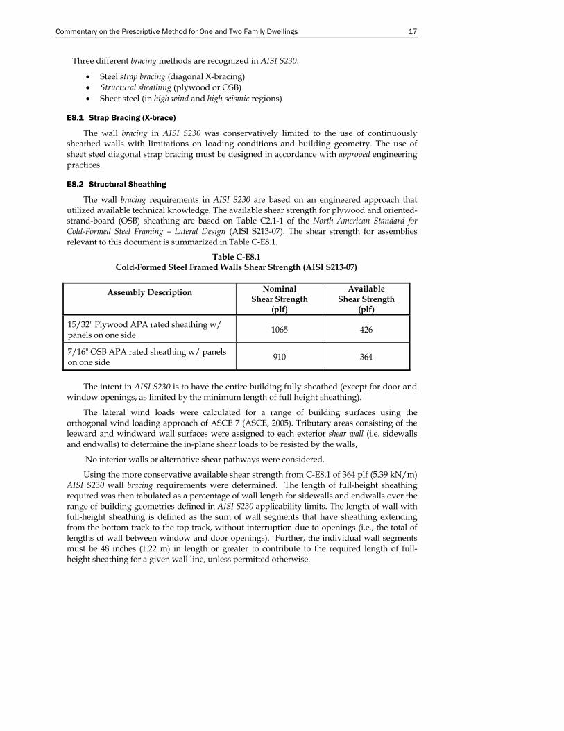
E8.2 Structural Sheathing
The wall bracing requirements in AISI S230 are based on an engineered approach that utilized available technical knowledge. The available shear strength for plywood and oriented- strand-board (OSB) sheathing are based on Table C2.1-1 of the North American Standard for Cold-Formed Steel Framing – Lateral Design (AISI S213-07). The shear strength for assemblies relevant to this document is summarized in Table C-E8.1.
Table C-E8.1 Cold-Formed Steel Framed Walls Shear Strength (AISI S213-07)
Assembly Description Nominal Shear Strength
(plf)
Available Shear Strength
(plf)
15/32" Plywood APA rated sheathing w/ panels on one side 1065 426
7/16" OSB APA rated sheathing w/ panels on one side 910 364
The intent in AISI S230 is to have the entire building fully sheathed (except for door and
window openings, as limited by the minimum length of full height sheathing).
The lateral wind loads were calculated for a range of building surfaces using the orthogonal wind loading approach of ASCE 7 (ASCE, 2005). Tributary areas consisting of the leeward and windward wall surfaces were assigned to each exterior shear wall (i.e. sidewalls and endwalls) to determine the in-plane shear loads to be resisted by the walls,
No interior walls or alternative shear pathways were considered.
Using the more conservative available shear strength from C-E8.1 of 364 plf (5.39 kN/m) AISI S230 wall bracing requirements were determined. The length of full-height sheathing required was then tabulated as a percentage of wall length for sidewalls and endwalls over the range of building geometries defined in AISI S230 applicability limits. The length of wall with full-height sheathing is defined as the sum of wall segments that have sheathing extending from the bottom track to the top track, without interruption due to openings (i.e., the total of lengths of wall between window and door openings). Further, the individual wall segments must be 48 inches (1.22 m) in length or greater to contribute to the required length of full-height sheathing for a given wall line, unless permitted otherwise.
18 Commentary on AISI S230-07 w/S2-08
As a final step necessary for a basic prescriptive approach, the requirements were conservatively reduced to the minimum percent lengths of full-height sheathed wall shown in the wall-bracing table of the AISI S230. The only building geometry parameter retained was roof slope due to a significant impact on the wind loads transferred to the shear walls. Footnotes to the shear wall table provide additional information related to the proper applications of the requirements.
E8.3 Structural Sheathing Fastening
Fastening of structural sheathing is typically done at 6 inch (152 mm) spacing at the perimeters and 12 inch spacing (305 mm) in the field. When this spacing is reduced to 4 inches (102 mm) (perimeter spacing only), the percentage of full-height sheathing is permitted to be multiplied by 0.72.
E8.4 Hold-down Requirements
A hold-down anchor shall consist of an approved strap or bracket adequately attached to the stud and anchored to the foundation, floor, or wall below to form a continuous load path to the foundation. In wind conditions greater than 100 mph (161 km/hr) exposure C, hold-down anchors in accordance with Table E2-1 are required to stabilize the shear walls. Hold-down anchors may also be added to reduce the amount of full-height sheathing required, or to increase the shear (racking) strength of the wall.
E9 Exterior Wall Covering
It is required that exterior coverings be installed in accordance with the recommendations of the manufacturer. AISI S230 limits the total exterior envelope dead load (total load = stud framing plus wall coverings) to 10 psf (0.48 kN/m2). If the total exterior envelope dead load exceeds that value, then the walls must be engineered for that load (see Table A1-2 for maximum wall dead loads in high seismic areas).
E11 Braced Walls in High Wind Areas and High Seismic Areas
E11.1 General
This section provides additional shear wall requirements for buildings located in high seismic areas (i.e., Seismic Design Categories D0, D1, D2 and E) or high wind areas (i.e., wind speed between 100 to 130 mph (161 to 209 km/hr)). In high seismic areas, buildings are required to comply with Sections E11 and E12; and in high wind areas, buildings are required to comply with the requirements in Sections E11 and E13.
The following general assumptions and building configurations were used in developing the high seismic tables and high wind provisions:
• Provisions and tables are limited to buildings no more than two-stories. • Provisions and tables are limited to buildings on slab-on-grade or spread footing
with stemwall foundation system with a single top of slab/top of stemwall elevation.
• Wall clear heights are limited to 8, 9, and 10 feet (2.44, 2.74 and 3.05 m). • Maximum roof slope is limited to 6.9:12. • All ceilings are considered leveled (i.e., no offsets or cathedral ceilings).
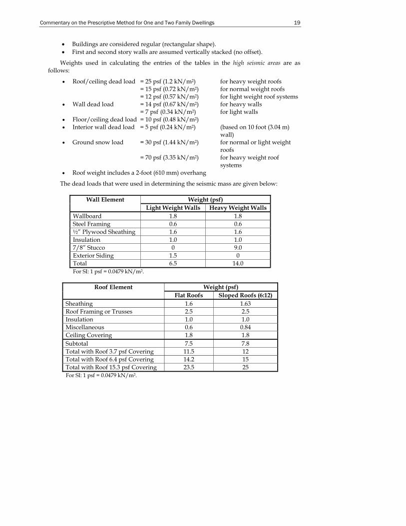
Commentary on the Prescriptive Method for One and Two Family Dwellings 19
• Buildings are considered regular (rectangular shape). • First and second story walls are assumed vertically stacked (no offset).
Weights used in calculating the entries of the tables in the high seismic areas are as follows:
• Roof/ceiling dead load = 25 psf (1.2 kN/m2) for heavy weight roofs = 15 psf (0.72 kN/m2) for normal weight roofs = 12 psf (0.57 kN/m2) for light weight roof systems
• Wall dead load = 14 psf (0.67 kN/m2) for heavy walls = 7 psf (0.34 kN/m2) for light walls
• Floor/ceiling dead load = 10 psf (0.48 kN/m2) • Interior wall dead load = 5 psf (0.24 kN/m2) (based on 10 foot (3.04 m)
wall) • Ground snow load = 30 psf (1.44 kN/m2) for normal or light weight
roofs = 70 psf (3.35 kN/m2) for heavy weight roof systems
• Roof weight includes a 2-foot (610 mm) overhang
The dead loads that were used in determining the seismic mass are given below:
Weight (psf) Wall Element Light Weight Walls Heavy Weight Walls
Wallboard 1.8 1.8 Steel Framing 0.6 0.6 ½” Plywood Sheathing 1.6 1.6 Insulation 1.0 1.0 7/8” Stucco 0 9.0 Exterior Siding 1.5 0 Total 6.5 14.0 For SI: 1 psf = 0.0479 kN/m2.
Roof Element Weight (psf)
Flat Roofs Sloped Roofs (6:12) Sheathing 1.6 1.63 Roof Framing or Trusses 2.5 2.5 Insulation 1.0 1.0 Miscellaneous 0.6 0.84 Ceiling Covering 1.8 1.8 Subtotal 7.5 7.8 Total with Roof 3.7 psf Covering 11.5 12 Total with Roof 6.4 psf Covering 14.2 15 Total with Roof 15.3 psf Covering 23.5 25 For SI: 1 psf = 0.0479 kN/m2.
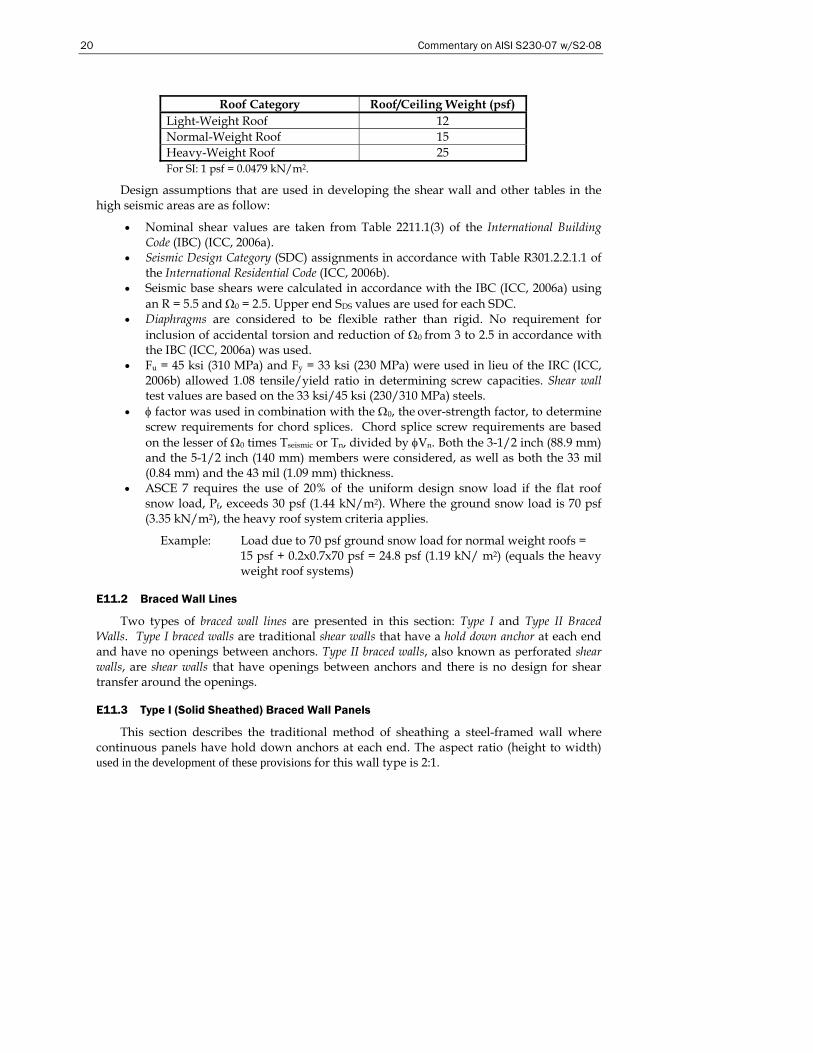
20 Commentary on AISI S230-07 w/S2-08
Roof Category Roof/Ceiling Weight (psf)
Light-Weight Roof 12 Normal-Weight Roof 15 Heavy-Weight Roof 25 For SI: 1 psf = 0.0479 kN/m2.
Design assumptions that are used in developing the shear wall and other tables in the high seismic areas are as follow:
• Nominal shear values are taken from Table 2211.1(3) of the International Building Code (IBC) (ICC, 2006a).
• Seismic Design Category (SDC) assignments in accordance with Table R301.2.2.1.1 of the International Residential Code (ICC, 2006b).
• Seismic base shears were calculated in accordance with the IBC (ICC, 2006a) using an R = 5.5 and Ω0 = 2.5. Upper end SDS values are used for each SDC.
• Diaphragms are considered to be flexible rather than rigid. No requirement for inclusion of accidental torsion and reduction of Ω0 from 3 to 2.5 in accordance with the IBC (ICC, 2006a) was used.
• Fu = 45 ksi (310 MPa) and Fy = 33 ksi (230 MPa) were used in lieu of the IRC (ICC, 2006b) allowed 1.08 tensile/yield ratio in determining screw capacities. Shear wall test values are based on the 33 ksi/45 ksi (230/310 MPa) steels.
• φ factor was used in combination with the Ω0, the over-strength factor, to determine screw requirements for chord splices. Chord splice screw requirements are based on the lesser of Ω0 times Tseismic or Tn, divided by φVn. Both the 3-1/2 inch (88.9 mm) and the 5-1/2 inch (140 mm) members were considered, as well as both the 33 mil (0.84 mm) and the 43 mil (1.09 mm) thickness.
• ASCE 7 requires the use of 20% of the uniform design snow load if the flat roof snow load, Pf, exceeds 30 psf (1.44 kN/m2). Where the ground snow load is 70 psf (3.35 kN/m2), the heavy roof system criteria applies.
Example: Load due to 70 psf ground snow load for normal weight roofs = 15 psf + 0.2x0.7x70 psf = 24.8 psf (1.19 kN/ m2) (equals the heavy weight roof systems)
E11.2 Braced Wall Lines
Two types of braced wall lines are presented in this section: Type I and Type II Braced Walls. Type I braced walls are traditional shear walls that have a hold down anchor at each end and have no openings between anchors. Type II braced walls, also known as perforated shear walls, are shear walls that have openings between anchors and there is no design for shear transfer around the openings.
E11.3 Type I (Solid Sheathed) Braced Wall Panels
This section describes the traditional method of sheathing a steel-framed wall where continuous panels have hold down anchors at each end. The aspect ratio (height to width) used in the development of these provisions for this wall type is 2:1.
Commentary on the Prescriptive Method for One and Two Family Dwellings 21
E11.4 Type II (Perforated) Braced Wall Lines
The Type II Braced Wall, or perforated shear wall method, requires hold down anchors at each end of each wall rather than at each end of continuous panels. The aspect ratio (height to width) is also 2:1 for this wall type. For a defined Type II (perforated shear wall), the adjustment factors given in Table E11-2 define the magnitude by which the strength of an otherwise solid wall must be divided to get the strength of the Type II (perforated) wall. The tabulated values, adopted from wood frame construction, were justified on the basis of a series of full-scale reversed cyclic tests by Vagh, Dolan and Easterling (2000) in which it was demonstrated that the tested wall capacities were greater than the reductions that are required by Table E11-2.
E12 Braced Wall Design in High Seismic Areas
E12.2 Braced Wall Anchorage and Chord Stud Requirements
AISI S230 permits the tabulated values to be divided by 1.4 when comparing requirements with manufacturer’s published strengths expressed as allowable loads. The derivation of this adjustment factor is: φ x Ω = 0.55 x 2.5 = 1.4. In earlier editions of cold-formed steel lateral design provisions, the resistance factor was set at 0.55 to reflect the 1.4 value used in the UBC to compute allowable seismic loads (1.4 approx. = 0.55 x 2.5).
E13 Braced Wall Design in High Wind Areas
E13.3 Connections of Walls in High Wind Areas
E13.3.2 Uplift Connection – Wall Assembly to Wall Assembly
AISI S230 permits the tabulated values to be divided by 1.3 when comparing requirements with manufacturers’ published strengths expressed as allowable loads. The derivation of this adjustment factor is: φ x Ω = 0.60 x 2.0 = 1.3.
E13.3.3 Header Uplift Connections
For back-to-back headers supporting roof and ceiling only, these provisions require that uplift straps be installed on both sides of the header beam (inside and outside of the wall) in order to minimize any effect of torsion. This requirement is based on engineering judgment and recognizes that the back-to-back header lacks sufficient torsional strength and stiffness. For back-to-back headers supporting loads from one floor, roof and ceiling, and for any box and double L-headers, a single uplift strap is permitted and may be installed on either side of the header beam.
22 Commentary on AISI S230-07 w/S2-08
F. ROOF FRAMING
F1 Roof Construction
Roof trusses are not prescriptively addressed in AISI S230, but are permitted, in accordance with Section F6, and must be designed by a design professional. Also roof girders are also not addressed in AISI S230.
F2 Ceiling Joists
F2.1 Minimum Ceiling Joist Size
Ceiling joist tables in AISI S230 provide the maximum allowable ceiling joist spans for two loading conditions: 10 psf (0.48 kN/m2) and 20 psf (0.96 kN/m2) attic live loads.
For the design of ceiling joists, for the following design considerations were evaluated:
• Flexural yielding • Flexural buckling • Web crippling (not required if bearing stiffeners are specified) • Shear • Vertical deflection
The engineering approach used to develop ceiling joist span tables for AISI S230 is similar to that used for floor joists with the exception of the magnitude of dead and live loads.
F2.2 Ceiling Joist Bearing Stiffeners
AISI S230 enables the selection of ceiling joists based on the use of bearing stiffeners.
F2.3 Ceiling Joist Bottom Flange Bracing
Gypsum board (i.e. finished ceilings) is considered to be adequate bracing for the bottom (tension) flanges of the ceiling joists. Steel strapping can also be used as bottom flange bracing for ceiling joists.
F2.4 Ceiling Joist Top Flange Bracing
For braced top (compression) flanges it is necessary for steel strapping to have blocking (or bridging) installed at a maximum spacing of 12 feet (3.66 m) and at the termination of all straps. Moreover, the ends of steel straps are to be fastened to a stable component of the building if end blocking is not installed. Ceiling joist tables provide spans for braced, as well as unbraced, top flanges.
F2.5 Ceiling Joist Splicing
Splicing of ceiling joists in AISI S230 requires an approved design except when lapped ceiling joists occur at an interior bearing wall.
Commentary on the Prescriptive Method for One and Two Family Dwellings 23
F3 Roof Rafters
F3.1 Minimum Roof Rafter Sizes
The roof rafter span table was designed based primarily on gravity loads, hence the roof rafter spans are based on the horizontal projection of the roof rafter, regardless of the slope. The gravity loads consist of a 7 psf (0.34 kN/m2) dead load and the greater of a 16 psf (0.77 kN/m2) live load or the applied roof snow load. Unbalanced snow loads in accordance with ASCE 7 were considered.
Wind load effects are developed by a procedure that equates the wind loads to equivalent snow loads as shown in Table F3.2 of AISI S230. Wind pressures were calculated using the ASCE 7 (ASCE, 2005) Components and Cladding coefficients. Wind loads acting perpendicular to the plane of the roof rafter were adjusted to represent loads acting orthogonal to the horizontal projection of the roof rafter. Wind loads were examined for both uplift and downward loads and the worst case was correlated to a corresponding snow load.
Permissible roof slopes range between 3:12 through 12:12 and more importantly, the roof system must consist of both ceiling joists (i.e. acting as rafter ties) and roof rafters. AISI S230 does not currently address cathedral ceilings because a prescriptive ridge beam and post design is not provided.
Lapped ceiling joists must be connected with the same screw size and number (or more) as the heel joint connection to ensure adequate transfer of tension loads across the spliced joint. The splice must occur over an interior bearing wall.
F3.1.1 Eave Overhang
A 24 inch (610 mm) eave overhang was used when calculating the roof rafter spans in AISI S230.
F3.1.1 Rake Overhang
In 2007, limitations and details were added to AISI S230 to clarify the installation requirements at gable endwalls, based on a study at University of Missouri-Rolla (Downey et al., 2005).
F3.2 Roof Rafter Support Brace
The support brace is used to increase the span of a particular member. When the brace is used, the roof rafter span is determined from the heel joint to the brace point or from the ridge member to the brace point (horizontal projection), whichever is greater.
F3.3 Roof Rafter Splice
The roof rafter spans provided in AISI S230 are based on the assumption that the members are continuous, with no splices. Therefore, roof rafters are not to be spliced without an approved design.
F3.5 Roof Rafter Bottom Flange Bracing
The bracing requirements provided in AISI S230 are commonly used in residential steel construction and are based on engineering judgment.

24 Commentary on AISI S230-07 w/S2-08
F4 Hip Framing
Prior to the 2007 edition of this standard, roof framing was limited to roof rafters and ceiling joists. Hip and valley framing options were added in 2007, based on research at the University of Missouri -Rolla (Waldo et al., 2006).
F5 Framing of Openings in Roofs and Ceilings
The requirements of this section are based on engineering judgment.
F6 Roof Trusses
AISI S230 does not contain provisions for roof trusses, which must have an approved design. This section is included so that pre-engineered roof trusses may be used in conjunction with this document. The North American Standard for Cold-Formed Steel Framing – Truss Design (AISI S214-07) should be consulted for the truss design.
F7 Ceiling and Roof Diaphragms
Roof diaphragms are required to adequately transfer shear loads to the braced wall lines in a structure. The load transfer typically accomplished by sheathing the roof-framing members with wood structural panels. Shear values used in the design of roof diaphragms were taken from the North American Standard for Cold-Formed Steel Framing – Lateral Design (AISI S213-07). Additional requirements for steel roof diaphragms in high wind areas (i.e., 110 mph (177 km/hr) or greater wind speed) or high seismic areas (i.e., Seismic Design Category D0, D1, D2 and E) are specified in Section F6.1 and F6.2.
Ceiling diaphragms are also required to adequately transfer shear loads to the braced wall lines in a structure. The load transfer typically accomplished by sheathing the ceiling-framing members with gypsum board or wood structural panels. Shear values used in the design of ceiling diaphragms were taken from the North American Standard for Cold-Formed Steel Framing – Lateral Design (AISI S213-07).
Commentary on the Prescriptive Method for One and Two Family Dwellings 25
PART 2 – DESIGN EXAMPLES
FOR THE STANDARD FOR COLD-FORMED STEEL FRAMING –
PRESCRIPTIVE METHOD FOR ONE AND TWO FAMILY DWELLINGS
A. INTRODUCTION
Part 2 illustrates the basis for the development of the prescriptive requirements for cold-formed steel framing. Part 2 validates tabulated values through the use of design examples for AISI S230 (AISI S230, 2007d). These design examples are based primarily on existing available reference standards such as the American Iron and Steel Institute North American Specification for the Design of Cold-Formed Steel Structural Members (AISI, 2007), the American Society of Civil Engineers standard ASCE-7 Minimum Design Loads for Buildings and Other Structures (ASCE, 2005) and the American Iron and Steel Institute North American Standard for Cold-Formed Steel Framing – Header Design (AISI, 2007c).
These design examples are shown in U.S. customary units. For appropriate conversions to the International System of Units (SI), refer to Appendix A.
A1 Member Properties
All section properties and member capacities were calculated using either the 1996 Specification (AISI, 1996) or the 2001 Specification (AISI, 2001). Refer to Section A3 in Part 1 for a discussion of referenced documents. Floor and ceiling joist members were assumed to have holes with 2½” depth x 4 ½ ” length located along the centerline of the web. This is the maximum hole size permitted by AISI S100. Studs and other structural elements were assumed to have holes with 1½” wide x 4” long along the centerline of the web.
Minimum Fy = 33 ksi Minimum Fu = 45 ksi Minimum Fy = 50 ksi Minimum Fu = 65 ksi
The design thickness (minimum thickness divided by 0.95) used in calculating member capacity and section properties was based on the Specification Section A2.4.
A2 Design Loads
The following loads were used in designing the various steel-framing members:
Ceiling dead load = 5 psf Roof dead load = 7 psf Floor dead load = 10 psf First floor live load = 40 psf Second floor live load = 30 psf Wall dead load = 10 psf Attic live load = 10 psf for attics with no storage Attic live load = 20 psf for attics with storage Wind load = Varies by wind speed and exposure (3-sec. Gust) Seismic Load = Varies by Seismic Design Category: A, B, C, D0, D1, D2, or
E Roof snow load = 0.7 x Ground snow load (unbalanced snow loads were
considered)
26 Commentary on AISI S230-07 w/S2-08
Roof live load = greater of 16 psf live load or the applied snow load
A2.1 Roof Snow Loads
Applied roof snow loads were calculated by multiplying the ground snow load by a 0.7 conversion factor in accordance with ASCE 7 (ASCE, 2005). No further reductions were made for special cases.
The sloped roof snow load, Ps = (Cs) (Pf), where Pf is the flat roof snow load. Pf = 0.7 Ce Ct I Pg Cs Cs is the roof slope factor ranging from approximately 0.1 to 1.0. A slope factor of
1.0 was judged to be conservative for houses with roof slopes from 3:12 to 12:12. Ce Ce is the exposure factor depending on the location of the house. Ce varies from
0.8 for windy, unsheltered areas, to 1.2 for heavily sheltered areas. A factor of 1.0 was deemed reasonable for residential buildings that are partially exposed (ASCE 7, Table 7-2).
Ct Ct is a thermal factor that varies from 1.0 for heated structures to 1.2 for unheated structures. The thermal factor should be used based on the thermal condition that is likely to exist during the life of the structure. Houses are typically considered heated structures with Ct = 1.0 (ASCE 7, Table 7-3).
I I is the importance factor based on building classification. Houses are typically Category II structures, with an importance factor of 1.0 (ASCE 7, Table 7-4).
Pg Pg is the ground snow load from the ASCE 7 estimated ground snow map (psf).
Unbalanced snow loads were considered but sliding snow loads, and snow drifts on lower roofs were not considered. Rain-on-snow surcharge load was also not considered in the calculations because the roof slopes in this document exceed the ½-inch per foot requirement by ASCE 7 for rain-on-snow surcharge to be considered. Therefore, the flat roof snow load was computed as: (1.0)(0.7)(1.0)(1.0)(Pg) = 0.7 Pg.
A2.2 Wind Loads
The design tables contained in AISI S230 were generated at different times and, consequently, using different editions of ASCE 7. For example, tables for the lateral provisions were developed using the 1998 edition whereas the wall stud tables were updated using the 2005 edition of ASCE 7. Every effort was made in this Commentary to cite the applicable edition of ASCE 7.
As an example, wind loads developed for floor and roof diaphragms and braced walls for wind were based on 3-second gust wind speeds ranging from 85 to 130 mph, Exposure A, B, or C in accordance with ASCE 7-98.
q = 0.00256Kz(GCp + GCpi)(V2 x I) where Kz = 0.87 at 20 feet, for Exposure C GCp = 0 for Zone 1, Tributary area = 75 ft2, GCpi = ± 0.25 for Components and Cladding, interior pressure, enclosed buildings I = 1.0 for residential buildings in areas with wind speed < 100 mph
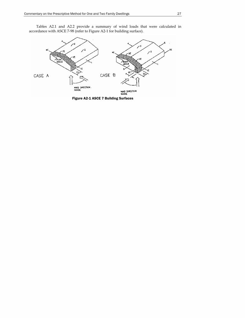
Commentary on the Prescriptive Method for One and Two Family Dwellings 27
Tables A2.1 and A2.2 provide a summary of wind loads that were calculated in accordance with ASCE 7-98 (refer to Figure A2-1 for building surface).
Figure A2-1 ASCE 7 Building Surfaces
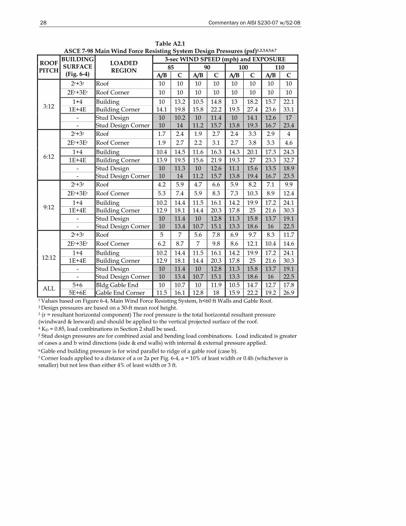
28 Commentary on AISI S230-07 w/S2-08
Table A2.1 ASCE 7-98 Main Wind Force Resisting System Design Pressures (psf)1,2,3,4,5,6,7
3-sec WIND SPEED (mph) and EXPOSURE 85 90 100 110
ROOF PITCH
BUILDING SURFACE (Fig. 6-4)
LOADED REGION
A/B C A/B C A/B C A/B C 2r+3r Roof 10 10 10 10 10 10 10 10
2Er+3Er Roof Corner 10 10 10 10 10 10 10 10 1+4 Building 10 13.2 10.5 14.8 13 18.2 15.7 22.1
1E+4E Building Corner 14.1 19.8 15.8 22.2 19.5 27.4 23.6 33.1 - Stud Design 10 10.2 10 11.4 10 14.1 12.6 17
3:12
- Stud Design Corner 10 14 11.2 15.7 13.8 19.3 16.7 23.4 2r+3r Roof 1.7 2.4 1.9 2.7 2.4 3.3 2.9 4
2Er+3Er Roof Corner 1.9 2.7 2.2 3.1 2.7 3.8 3.3 4.6 1+4 Building 10.4 14.5 11.6 16.3 14.3 20.1 17.3 24.3
1E+4E Building Corner 13.9 19.5 15.6 21.9 19.3 27 23.3 32.7 - Stud Design 10 11.3 10 12.6 11.1 15.6 13.5 18.9
6:12
- Stud Design Corner 10 14 11.2 15.7 13.8 19.4 16.7 23.5 2r+3r Roof 4.2 5.9 4.7 6.6 5.9 8.2 7.1 9.9
2Er+3Er Roof Corner 5.3 7.4 5.9 8.3 7.3 10.3 8.9 12.4 1+4 Building 10.2 14.4 11.5 16.1 14.2 19.9 17.2 24.1
1E+4E Building Corner 12.9 18.1 14.4 20.3 17.8 25 21.6 30.3 - Stud Design 10 11.4 10 12.8 11.3 15.8 13.7 19.1
9:12
- Stud Design Corner 10 13.4 10.7 15.1 13.3 18.6 16 22.5 2r+3r Roof 5 7 5.6 7.8 6.9 9.7 8.3 11.7
2Er+3Er Roof Corner 6.2 8.7 7 9.8 8.6 12.1 10.4 14.6 1+4 Building 10.2 14.4 11.5 16.1 14.2 19.9 17.2 24.1
1E+4E Building Corner 12.9 18.1 14.4 20.3 17.8 25 21.6 30.3 - Stud Design 10 11.4 10 12.8 11.3 15.8 13.7 19.1
12:12
- Stud Design Corner 10 13.4 10.7 15.1 13.3 18.6 16 22.5 5+6 Bldg Gable End 10 10.7 10 11.9 10.5 14.7 12.7 17.8 ALL
5E+6E Gable End Corner 11.5 16.1 12.8 18 15.9 22.2 19.2 26.9 1 Values based on Figure 6-4, Main Wind Force Resisting System, h<60 ft Walls and Gable Roof. 2 Design pressures are based on a 30-ft mean roof height. 3 (r = resultant horizontal component) The roof pressure is the total horizontal resultant pressure (windward & leeward) and should be applied to the vertical projected surface of the roof. 4 KD = 0.85, load combinations in Section 2 shall be used. 5 Stud design pressures are for combined axial and bending load combinations. Load indicated is greater of cases a and b wind directions (side & end walls) with internal & external pressure applied. 6 Gable end building pressure is for wind parallel to ridge of a gable roof (case b). 7 Corner loads applied to a distance of a or 2a per Fig. 6-4, a = 10% of least width or 0.4h (whichever is smaller) but not less than either 4% of least width or 3 ft.
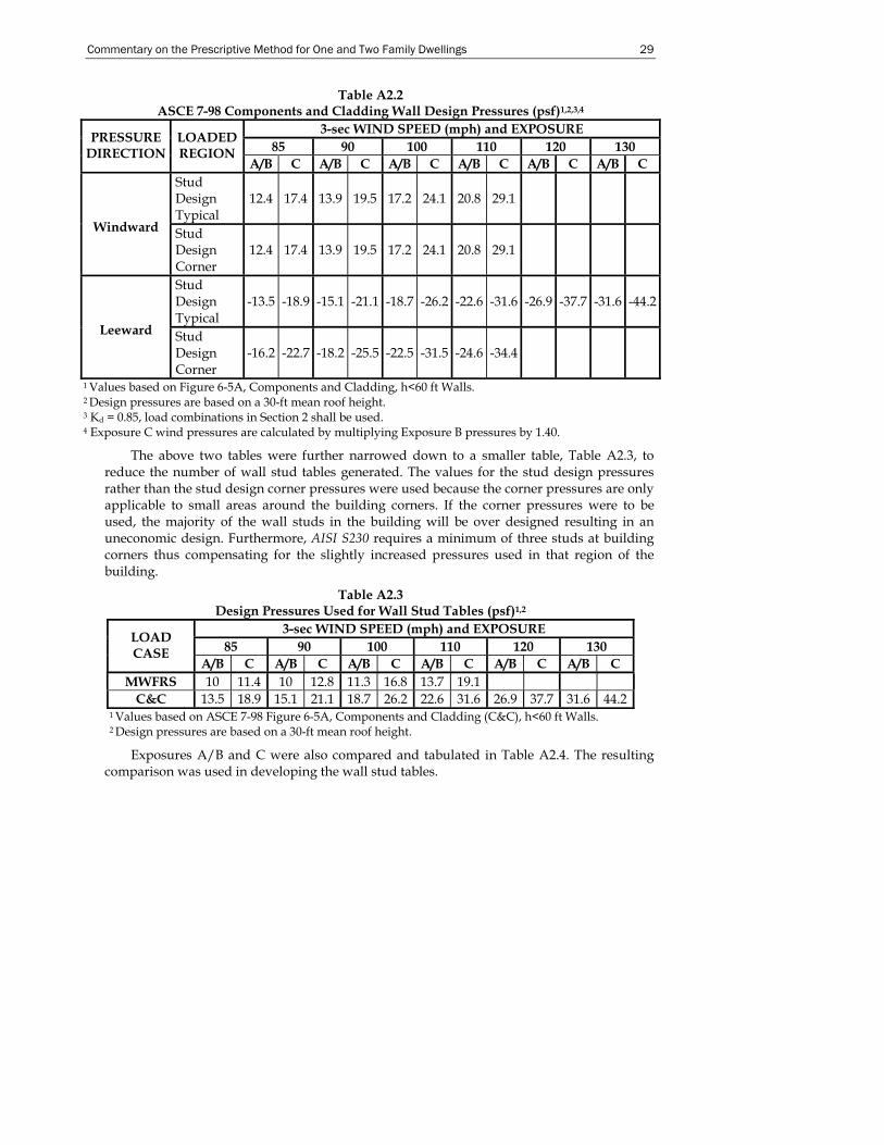
Commentary on the Prescriptive Method for One and Two Family Dwellings 29
Table A2.2 ASCE 7-98 Components and Cladding Wall Design Pressures (psf)1,2,3,4
3-sec WIND SPEED (mph) and EXPOSURE 85 90 100 110 120 130
PRESSURE DIRECTION
LOADED REGION
A/B C A/B C A/B C A/B C A/B C A/B C Stud Design Typical
12.4 17.4 13.9 19.5 17.2 24.1 20.8 29.1
Windward Stud Design Corner
12.4 17.4 13.9 19.5 17.2 24.1 20.8 29.1
Stud Design Typical
-13.5 -18.9 -15.1 -21.1 -18.7 -26.2 -22.6 -31.6 -26.9 -37.7 -31.6 -44.2
Leeward Stud Design Corner
-16.2 -22.7 -18.2 -25.5 -22.5 -31.5 -24.6 -34.4
1 Values based on Figure 6-5A, Components and Cladding, h<60 ft Walls. 2 Design pressures are based on a 30-ft mean roof height. 3 Kd = 0.85, load combinations in Section 2 shall be used. 4 Exposure C wind pressures are calculated by multiplying Exposure B pressures by 1.40.
The above two tables were further narrowed down to a smaller table, Table A2.3, to reduce the number of wall stud tables generated. The values for the stud design pressures rather than the stud design corner pressures were used because the corner pressures are only applicable to small areas around the building corners. If the corner pressures were to be used, the majority of the wall studs in the building will be over designed resulting in an uneconomic design. Furthermore, AISI S230 requires a minimum of three studs at building corners thus compensating for the slightly increased pressures used in that region of the building.
Table A2.3 Design Pressures Used for Wall Stud Tables (psf)1,2
3-sec WIND SPEED (mph) and EXPOSURE 85 90 100 110 120 130
LOAD CASE
A/B C A/B C A/B C A/B C A/B C A/B C MWFRS 10 11.4 10 12.8 11.3 16.8 13.7 19.1
C&C 13.5 18.9 15.1 21.1 18.7 26.2 22.6 31.6 26.9 37.7 31.6 44.2 1 Values based on ASCE 7-98 Figure 6-5A, Components and Cladding (C&C), h<60 ft Walls. 2 Design pressures are based on a 30-ft mean roof height.
Exposures A/B and C were also compared and tabulated in Table A2.4. The resulting comparison was used in developing the wall stud tables.
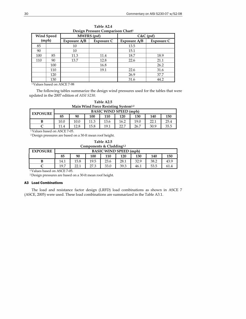
30 Commentary on AISI S230-07 w/S2-08
Table A2.4 Design Pressure Comparison Chart1
MWFRS (psf) C&C (psf) Wind Speed (mph) Exposure A/B Exposure C Exposure A/B Exposure C
85 10 13.5 90 10 15.1
100 85 11.3 11.4 18.7 18.9 110 90 13.7 12.8 22.6 21.1
100 16.8 26.2 110 19.1 22.6 31.6 120 26.9 37.7 130 31.6 44.2
1 Values based on ASCE 7-98
The following tables summarize the design wind pressures used for the tables that were updated in the 2007 edition of AISI S230.
Table A2.5 Main Wind Force Resisting System1,2
BASIC WIND SPEED (mph) EXPOSURE 85 90 100 110 120 130 140 150
B 10.0 10.0 11.3 13.6 16.2 19.0 22.1 25.4 C 11.4 12.8 15.8 19.1 22.7 26.7 30.9 35.5
1 Values based on ASCE 7-05. 2 Design pressures are based on a 30-ft mean roof height.
Table A2.5 Components & Cladding1,2
EXPOSURE BASIC WIND SPEED (mph) 85 90 100 110 120 130 140 150
B 14.1 15.8 19.5 23.6 28.1 32.9 38.2 43.9 C 19.7 22.1 27.3 33.0 39.3 46.1 53.5 61.4
1 Values based on ASCE 7-05. 2 Design pressures are based on a 30-ft mean roof height.
A3 Load Combinations
The load and resistance factor design (LRFD) load combinations as shown in ASCE 7 (ASCE, 2005) were used. These load combinations are summarized in the Table A3.1.
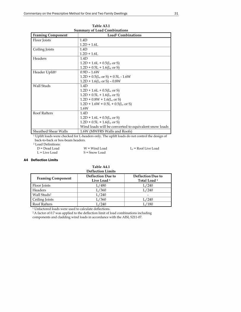
Commentary on the Prescriptive Method for One and Two Family Dwellings 31
Table A3.1 Summary of Load Combinations
Framing Component Load2 Combinations Floor Joists 1.4D
1.2D + 1.6L Ceiling Joists 1.4D
1.2D + 1.6L Headers 1.4D
1.2D + 1.6L + 0.5(Lr or S) 1.2D + 0.5L + 1.6(Lr or S)
Header Uplift1 0.9D – 1.6W 1.2D + 0.5(Lr or S) + 0.5L - 1.6W 1.2D + 1.6(Lr or S) – 0.8W
Wall Studs 1.4D 1.2D + 1.6L + 0.5(Lr or S) 1.2D + 0.5L + 1.6(Lr or S) 1.2D + 0.8W + 1.6(Lr or S) 1.2D + 1.6W + 0.5L + 0.5(Lr or S) 1.6W
Roof Rafters 1.4D 1.2D + 1.6L + 0.5(Lr or S) 1.2D + 0.5L + 1.6(Lr or S) Wind loads will be converted to equivalent snow loads
Sheathed Shear Walls 1.6W (MWFRS Walls and Roofs) 1 Uplift loads were checked for L-headers only. The uplift loads do not control the design of back-to-back or box-beam headers.
2 Load Definitions: D = Dead Load W = Wind Load Lr = Roof Live Load L = Live Load S = Snow Load
A4 Deflection Limits
Table A4.1 Deflection Limits
Framing Component Deflection Due to Live Load 1
Deflection Due to
Total Load 1 Floor Joists L/480 L/240 Headers L/360 L/240 Wall Studs2 L/240 - Ceiling Joists L/360 L/240 Roof Rafters L/240 L/180 1 Unfactored loads were used to calculate deflections. 2 A factor of 0.7 was applied to the deflection limit of load combinations including components and cladding wind loads in accordance with the AISI, S211-07.
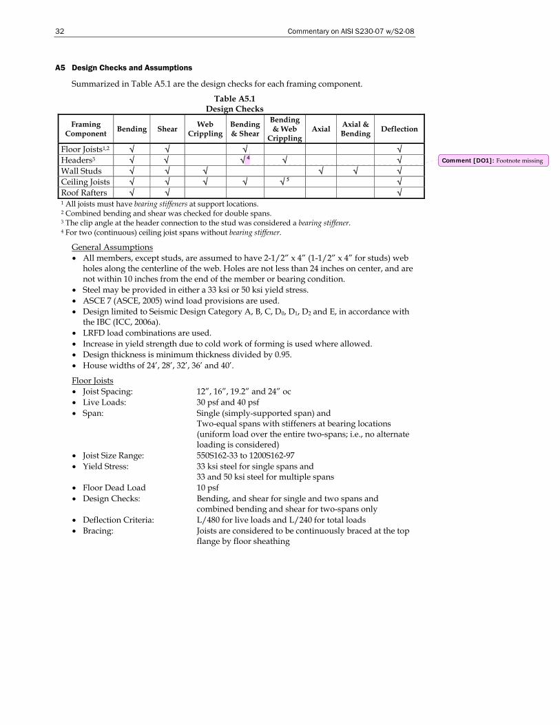
32 Commentary on AISI S230-07 w/S2-08
A5 Design Checks and Assumptions
Summarized in Table A5.1 are the design checks for each framing component.
Table A5.1 Design Checks
Framing Component Bending Shear Web
Crippling Bending & Shear
Bending & Web
Crippling Axial Axial &
Bending Deflection
Floor Joists1,2 √ √ √ √ Headers3 √ √ √ 4 √ √ Wall Studs √ √ √ √ √ √ Ceiling Joists √ √ √ √ √ 5 √ Roof Rafters √ √ √ 1 All joists must have bearing stiffeners at support locations. 2 Combined bending and shear was checked for double spans. 3 The clip angle at the header connection to the stud was considered a bearing stiffener. 4 For two (continuous) ceiling joist spans without bearing stiffener.
General Assumptions • All members, except studs, are assumed to have 2-1/2” x 4” (1-1/2” x 4” for studs) web
holes along the centerline of the web. Holes are not less than 24 inches on center, and are not within 10 inches from the end of the member or bearing condition.
• Steel may be provided in either a 33 ksi or 50 ksi yield stress. • ASCE 7 (ASCE, 2005) wind load provisions are used. • Design limited to Seismic Design Category A, B, C, D0, D1, D2 and E, in accordance with
the IBC (ICC, 2006a). • LRFD load combinations are used. • Increase in yield strength due to cold work of forming is used where allowed. • Design thickness is minimum thickness divided by 0.95. • House widths of 24’, 28’, 32’, 36’ and 40’.
Floor Joists • Joist Spacing: 12”, 16”, 19.2” and 24” oc • Live Loads: 30 psf and 40 psf • Span: Single (simply-supported span) and
Two-equal spans with stiffeners at bearing locations (uniform load over the entire two-spans; i.e., no alternate loading is considered)
• Joist Size Range: 550S162-33 to 1200S162-97 • Yield Stress: 33 ksi steel for single spans and
33 and 50 ksi steel for multiple spans • Floor Dead Load 10 psf • Design Checks: Bending, and shear for single and two spans and
combined bending and shear for two-spans only • Deflection Criteria: L/480 for live loads and L/240 for total loads • Bracing: Joists are considered to be continuously braced at the top
flange by floor sheathing
Comment [DO1]: Footnote missing
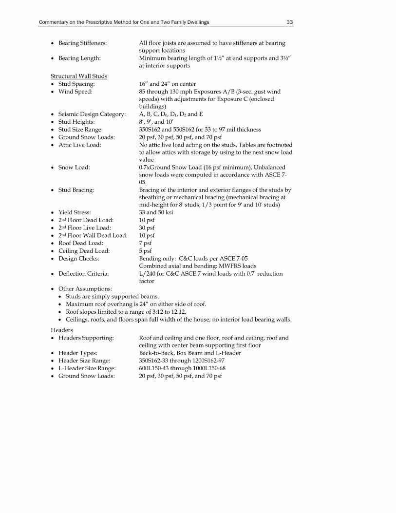
Commentary on the Prescriptive Method for One and Two Family Dwellings 33
• Bearing Stiffeners: All floor joists are assumed to have stiffeners at bearing support locations
• Bearing Length: Minimum bearing length of 1½” at end supports and 3½” at interior supports
Structural Wall Studs • Stud Spacing: 16” and 24” on center • Wind Speed: 85 through 130 mph Exposures A/B (3-sec. gust wind
speeds) with adjustments for Exposure C (enclosed buildings)
• Seismic Design Category: A, B, C, D0, D1, D2 and E • Stud Heights: 8’, 9’, and 10’ • Stud Size Range: 350S162 and 550S162 for 33 to 97 mil thickness • Ground Snow Loads: 20 psf, 30 psf, 50 psf, and 70 psf • Attic Live Load: No attic live load acting on the studs. Tables are footnoted
to allow attics with storage by using to the next snow load value
• Snow Load: 0.7xGround Snow Load (16 psf minimum). Unbalanced snow loads were computed in accordance with ASCE 7-05.
• Stud Bracing: Bracing of the interior and exterior flanges of the studs by sheathing or mechanical bracing (mechanical bracing at mid-height for 8' studs, 1/3 point for 9' and 10' studs)
• Yield Stress: 33 and 50 ksi • 2nd Floor Dead Load: 10 psf • 2nd Floor Live Load: 30 psf • 2nd Floor Wall Dead Load: 10 psf • Roof Dead Load: 7 psf • Ceiling Dead Load: 5 psf • Design Checks: Bending only: C&C loads per ASCE 7-05
Combined axial and bending: MWFRS loads • Deflection Criteria: L/240 for C&C ASCE 7 wind loads with 0.7 reduction
factor • Other Assumptions:
• Studs are simply supported beams. • Maximum roof overhang is 24” on either side of roof. • Roof slopes limited to a range of 3:12 to 12:12. • Ceilings, roofs, and floors span full width of the house; no interior load bearing walls.
Headers • Headers Supporting: Roof and ceiling and one floor, roof and ceiling, roof and
ceiling with center beam supporting first floor • Header Types: Back-to-Back, Box Beam and L-Header • Header Size Range: 350S162-33 through 1200S162-97 • L-Header Size Range: 600L150-43 through 1000L150-68 • Ground Snow Loads: 20 psf, 30 psf, 50 psf, and 70 psf
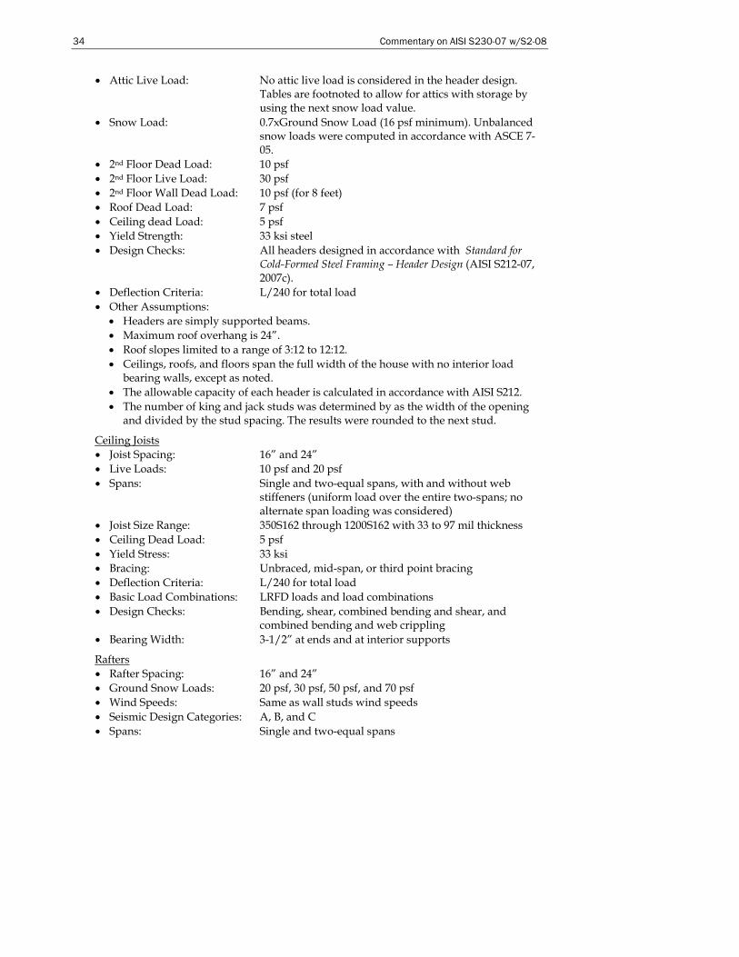
34 Commentary on AISI S230-07 w/S2-08
• Attic Live Load: No attic live load is considered in the header design. Tables are footnoted to allow for attics with storage by using the next snow load value.
• Snow Load: 0.7xGround Snow Load (16 psf minimum). Unbalanced snow loads were computed in accordance with ASCE 7-05.
• 2nd Floor Dead Load: 10 psf • 2nd Floor Live Load: 30 psf • 2nd Floor Wall Dead Load: 10 psf (for 8 feet) • Roof Dead Load: 7 psf • Ceiling dead Load: 5 psf • Yield Strength: 33 ksi steel • Design Checks: All headers designed in accordance with Standard for
Cold-Formed Steel Framing – Header Design (AISI S212-07, 2007c).
• Deflection Criteria: L/240 for total load • Other Assumptions:
• Headers are simply supported beams. • Maximum roof overhang is 24”. • Roof slopes limited to a range of 3:12 to 12:12. • Ceilings, roofs, and floors span the full width of the house with no interior load
bearing walls, except as noted. • The allowable capacity of each header is calculated in accordance with AISI S212. • The number of king and jack studs was determined by as the width of the opening
and divided by the stud spacing. The results were rounded to the next stud.
Ceiling Joists • Joist Spacing: 16” and 24” • Live Loads: 10 psf and 20 psf • Spans: Single and two-equal spans, with and without web
stiffeners (uniform load over the entire two-spans; no alternate span loading was considered)
• Joist Size Range: 350S162 through 1200S162 with 33 to 97 mil thickness • Ceiling Dead Load: 5 psf • Yield Stress: 33 ksi • Bracing: Unbraced, mid-span, or third point bracing • Deflection Criteria: L/240 for total load • Basic Load Combinations: LRFD loads and load combinations • Design Checks: Bending, shear, combined bending and shear, and
combined bending and web crippling • Bearing Width: 3-1/2” at ends and at interior supports
Rafters • Rafter Spacing: 16” and 24” • Ground Snow Loads: 20 psf, 30 psf, 50 psf, and 70 psf • Wind Speeds: Same as wall studs wind speeds • Seismic Design Categories: A, B, and C • Spans: Single and two-equal spans
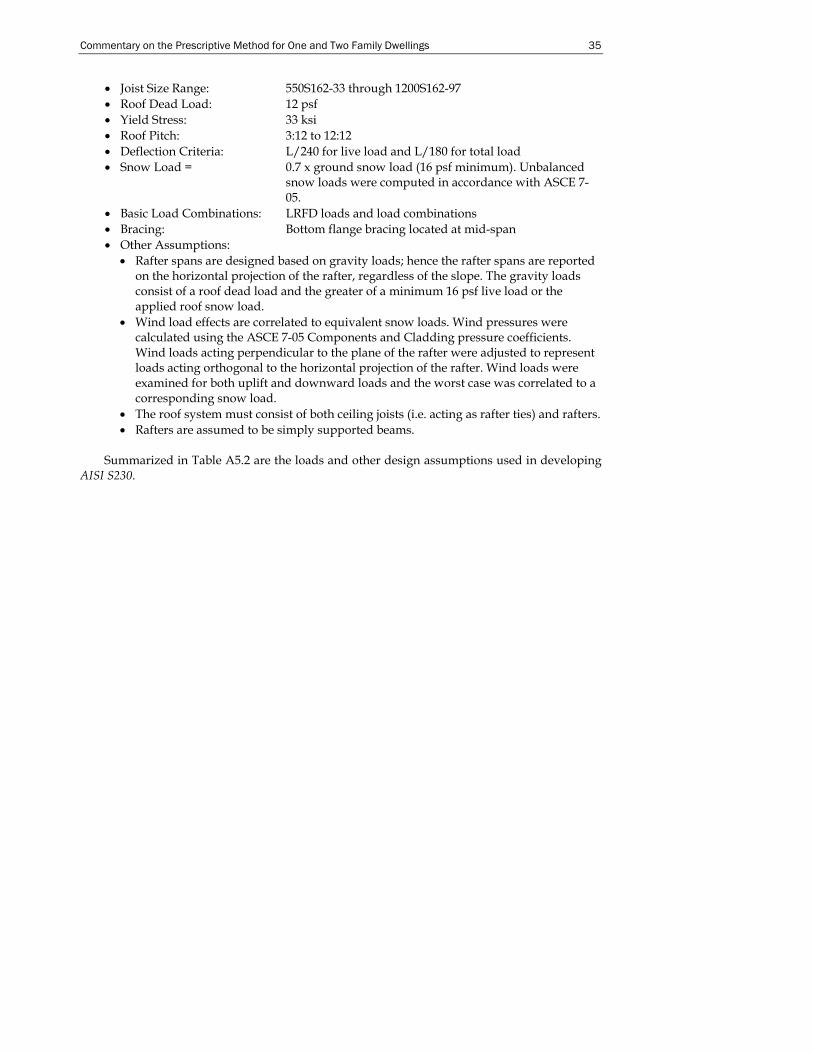
Commentary on the Prescriptive Method for One and Two Family Dwellings 35
• Joist Size Range: 550S162-33 through 1200S162-97 • Roof Dead Load: 12 psf • Yield Stress: 33 ksi • Roof Pitch: 3:12 to 12:12 • Deflection Criteria: L/240 for live load and L/180 for total load • Snow Load = 0.7 x ground snow load (16 psf minimum). Unbalanced
snow loads were computed in accordance with ASCE 7-05.
• Basic Load Combinations: LRFD loads and load combinations • Bracing: Bottom flange bracing located at mid-span • Other Assumptions:
• Rafter spans are designed based on gravity loads; hence the rafter spans are reported on the horizontal projection of the rafter, regardless of the slope. The gravity loads consist of a roof dead load and the greater of a minimum 16 psf live load or the applied roof snow load.
• Wind load effects are correlated to equivalent snow loads. Wind pressures were calculated using the ASCE 7-05 Components and Cladding pressure coefficients. Wind loads acting perpendicular to the plane of the rafter were adjusted to represent loads acting orthogonal to the horizontal projection of the rafter. Wind loads were examined for both uplift and downward loads and the worst case was correlated to a corresponding snow load.
• The roof system must consist of both ceiling joists (i.e. acting as rafter ties) and rafters. • Rafters are assumed to be simply supported beams.
Summarized in Table A5.2 are the loads and other design assumptions used in developing
AISI S230.
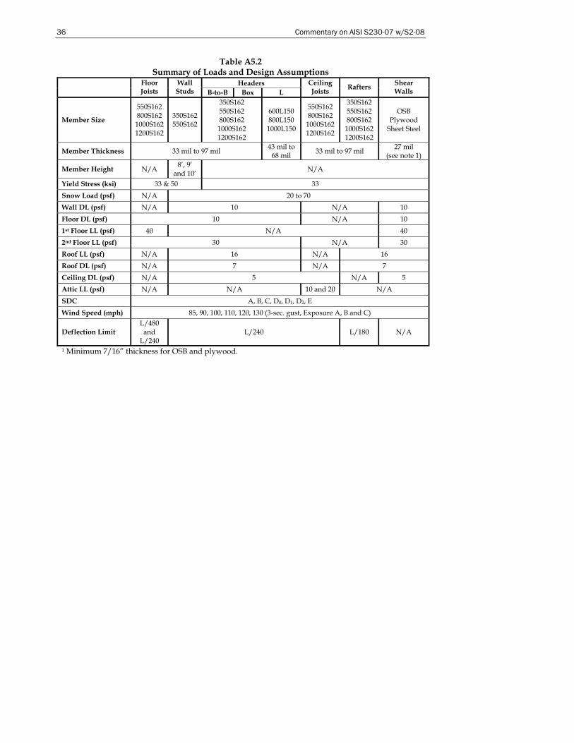
36 Commentary on AISI S230-07 w/S2-08
Table A5.2 Summary of Loads and Design Assumptions
Headers Floor Joists
Wall Studs B-to-B Box L
Ceiling Joists Rafters Shear
Walls
Member Size
550S162 800S162 1000S162 1200S162
350S162 550S162
350S162 550S162 800S162
1000S162 1200S162
600L150 800L150 1000L150
550S162 800S162
1000S162 1200S162
350S162 550S162 800S162
1000S162 1200S162
OSB Plywood
Sheet Steel
Member Thickness 33 mil to 97 mil 43 mil to 68 mil 33 mil to 97 mil 27 mil
(see note 1)
Member Height N/A 8’, 9’ and 10’ N/A
Yield Stress (ksi) 33 & 50 33 Snow Load (psf) N/A 20 to 70 Wall DL (psf) N/A 10 N/A 10 Floor DL (psf) 10 N/A 10 1st Floor LL (psf) 40 N/A 40 2nd Floor LL (psf) 30 N/A 30 Roof LL (psf) N/A 16 N/A 16 Roof DL (psf) N/A 7 N/A 7 Ceiling DL (psf) N/A 5 N/A 5 Attic LL (psf) N/A N/A 10 and 20 N/A SDC A, B, C, D0, D1, D2, E Wind Speed (mph) 85, 90, 100, 110, 120, 130 (3-sec. gust, Exposure A, B and C)
Deflection Limit L/480
and L/240
L/240 L/180 N/A
1 Minimum 7/16” thickness for OSB and plywood.
Commentary on the Prescriptive Method for One and Two Family Dwellings 37
D. FLOOR FRAMING DESIGN EXAMPLES
D1 Floor Joist Design
Calculate the allowable span for a 1000S162-54, Fy = 33 ksi, single span joist spaced at 24” (2’) on center, supporting a live load of 40 psf and a dead load of 10 psf. using the provisions of the AISI Specification (AISI,1996). The compression flange of the joist is laterally restrained by floor sheathing. For deflection checks, Δ = L/480 for live load only and Δ = L/240 for total loads (dead load + live load).
The maximum allowable joist span is the minimum span calculated based on shear, moment, and deflection.
D1.1 Shear Capacity
In accordance with Section C3.2 of AISI Specification, the nominal shear strength, Vn, is calculated to be 2,673 lb for a joist with 2 ½” deep web holes.
Use the design shear strength, φVn, to calculate the maximum unsupported span length.
2wLVn =φ
wV2L nφ
=
where w = factored uniform load (plf) = (1.2x10 + 1.6x40)(2) = 152 plf
15226739.02 ××
=L = L = 31.66’ = 31’-8”
D1.2 Moment Capacity
The nominal flexural strength, Mn, is 5,461 ft-lb, as calculated in accordance with Section C3.1.1 of the AISI Specification for a joist with 2-1/2” deep web hole.
For a simply supported span with the top flanges laterally supported:
8wLM
2n =φ
wM8L nφ
=
152546195.08 xxL =
L = 16.52 feet = 16’-6”
D1.3 Deflection Limit
The deflection equation for a simply supported span with distributed load is:
EI384wL5 4
=Δ 4 x )Limit Deflection(w5EI385L =
where L = Single span length (inches)
Ix = Effective moment of inertia for deflection= 9.8815 in4 w = 50 psf (24/12)for total load deflection check and 40 psf
(24/12)for live load deflection check
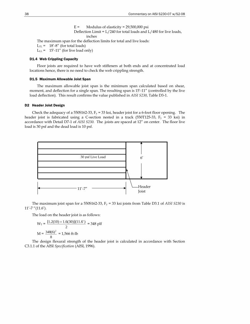
38 Commentary on AISI S230-07 w/S2-08
30 psf Live Load 6’
11’-7”
Header Joist
E = Modulus of elasticity = 29,500,000 psi Deflection Limit = L/240 for total loads and L/480 for live loads,
inches The maximum span for the deflection limits for total and live loads: LTL = 18’-8” (for total loads) LLL = 15’-11” (for live load only)
D1.4 Web Crippling Capacity
Floor joists are required to have web stiffeners at both ends and at concentrated load locations hence, there is no need to check the web crippling strength.
D1.5 Maximum Allowable Joist Span
The maximum allowable joist span is the minimum span calculated based on shear, moment, and deflection for a single span. The resulting span is 15’-11” (controlled by the live load deflection). This result confirms the value published in AISI S230, Table D3-1.
D2 Header Joist Design
Check the adequacy of a 550S162-33, Fy = 33 ksi, header joist for a 6-foot floor opening. The header joist is fabricated using a C-section nested in a track (550T125-33, Fy = 33 ksi) in accordance with Detail D7-1 of AISI S230. The .joists are spaced at 12” on center. The floor live load is 30 psf and the dead load is 10 psf.
The maximum joist span for a 550S162-33, Fy = 33 ksi joists from Table D3.1 of AISI S230 is 11’-7 “(11.6’).
The load on the header joist is as follows:
WT = 2
)'6.11)](30(6.1)10(2.1[ + = 348 plf
M = 8
)6(348 2 = 1,566 ft-lb
The design flexural strength of the header joist is calculated in accordance with Section C3.1.1 of the AISI Specification (AISI, 1996).
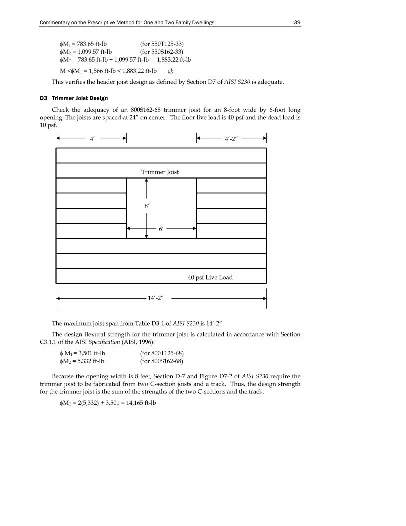
Commentary on the Prescriptive Method for One and Two Family Dwellings 39
φM1 = 783.65 ft-lb (for 550T125-33) φM2 = 1,099.57 ft-lb (for 550S162-33) φMT = 783.65 ft-lb + 1,099.57 ft-lb = 1,883.22 ft-lb
M <φMT = 1,566 ft-lb < 1,883.22 ft-lb ok
This verifies the header joist design as defined by Section D7 of AISI S230 is adequate.
D3 Trimmer Joist Design
Check the adequacy of an 800S162-68 trimmer joist for an 8-foot wide by 6-foot long opening. The joists are spaced at 24” on center. The floor live load is 40 psf and the dead load is 10 psf.
The maximum joist span from Table D3-1 of AISI S230 is 14’-2”.
The design flexural strength for the trimmer joist is calculated in accordance with Section C3.1.1 of the AISI Specification (AISI, 1996):
φ M1 = 3,501 ft-lb (for 800T125-68) φM2 = 5,332 ft-lb (for 800S162-68)
Because the opening width is 8 feet, Section D-7 and Figure D7-2 of AISI S230 require the
trimmer joist to be fabricated from two C-section joists and a track. Thus, the design strength for the trimmer joist is the sum of the strengths of the two C-sections and the track.
φMT = 2(5,332) + 3,501 = 14,165 ft-lb
8’
6’
14’-2”
40 psf Live Load
4’ 4’-2”
Trimmer Joist
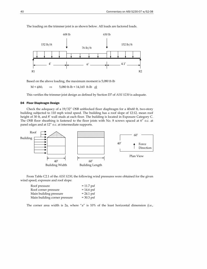
40 Commentary on AISI S230-07 w/S2-08
The loading on the trimmer joist is as shown below. All loads are factored loads.
Based on the above loading, the maximum moment is 5,080 ft-lb
M < φMT ⇒ 5,080 ft-lb < 14,165 ft-lb ok
This verifies the trimmer joist design as defined by Section D7 of AISI S230 is adequate.
D4 Floor Diaphragm Design
Check the adequacy of a 19/32” OSB unblocked floor diaphragm for a 40x60 ft, two-story building subjected to 110 mph wind speed. The building has a roof slope of 12:12, mean roof height of 30 ft, and 8’ wall studs at each floor. The building is located in Exposure Category C. The OSB floor sheathing is fastened to the floor joists with No. 8 screws spaced at 6” o.c. at panel edges and at 12” o.c. at intermediate supports.
From Table C2.1 of the AISI S230, the following wind pressures were obtained for the given wind speed, exposure and roof slope:
Roof pressure = 11.7 psf Roof corner pressure = 14.6 psf Main building pressure = 24.1 psf Main building corner pressure = 30.3 psf
The corner area width is 2a, where “a” is 10% of the least horizontal dimension (i.e.,
152 lb/ft 152 lb/ft 76 lb/ft
608 lb 630 lb
R1 R2
4’ 4.1’ 6’
40’
60’
Plan View
Force Direction
60’ Building Length
40’ Building Width
Building
Roof
Commentary on the Prescriptive Method for One and Two Family Dwellings 41
building width or building length) or 0.4 times the mean roof height, h which ever is smaller, but not less than either 4% of least horizontal dimension or 3 feet.
a = 0.10(40) = 4’ a = 0.4(30) = 12’ Therefore a = 4’ > 0.04(40) = 1.6’ or 3’ Use a = 4’ Corner area = 2a = 8’ Shear = (60’ – 16’)(8’)(24.1 psf) + 16’(8’)(30.3 psf) = 12,361 lbs Floor level diaphragm load = (12,361/2)/40 = 155 plf Factored diaphragm shear load = 155x1.6 = 248 plf
The North American Standard for Cold-Formed Steel Framing – Lateral Standard (AISI S213-07) does not stipulate the design shear strength for an unblocked 19/32” diaphragm. However S213-07 does stipulate a value or 442 plf for 7/16” OSB with No. 8 screws spaced at 6”.
The diaphragm in this example is therefore adequate (442 plf > 248 plf).
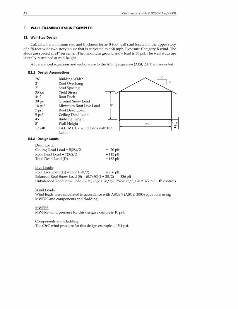
42 Commentary on AISI S230-07 w/S2-08
E. WALL FRAMING DESIGN EXAMPLES
E1 Wall Stud Design
Calculate the minimum size and thickness for an 8-foot wall stud located at the upper story of a 28-foot wide two-story house that is subjected to a 90 mph, Exposure Category B wind. The studs are spaced at 24” on center. The maximum ground snow load is 30 psf. The wall studs are laterally restrained at mid-height.
All referenced equations and sections are to the AISI Specification (AISI, 2001) unless noted.
E1.1 Design Assumptions
28’ Building Width 2’ Roof Overhang 2’ Stud Spacing 33 ksi Yield Stress 4:12 Roof Pitch 30 psf Ground Snow Load 16 psf Minimum Roof Live Load 7 psf Roof Dead Load 5 psf Ceiling Dead Load 45’ Building Length 8’ Wall Height L/240 C&C ASCE 7 wind loads with 0.7
factor
E1.2 Design Loads
Dead Load: Ceiling Dead Load = 5(28)/2 = 70 plf Roof Dead Load = 7(32)/2 = 112 plf Total Dead Load (D) = 182 plf Live Loads: Roof Live Load (Lr) = 16(2 + 28/2) = 256 plf Balanced Roof Snow Load (S) = (0.7x30)(2 + 28/2) = 336 plf Unbalanced Roof Snow Load (S) = (30)(2 + 28/2)(0.75x28+2/2)/28 = 377 plf controls Wind Loads: Wind loads were calculated in accordance with ASCE 7 (ASCE, 2005) equations using MWFRS and components and cladding. MWFRS: MWFRS wind pressure for this design example is 10 psf. Components and Cladding: The C&C wind pressure for this design example is 15.1 psf.
28’
8’
12 4
2’

Commentary on the Prescriptive Method for One and Two Family Dwellings 43
E1.3 Load Combinations
1. 1.4D 2. 1.2D + 1.6L + 0.5(Lr or S) 3. 1.2D + 0.5L + 1.6(Lr or S) 4. 1.2D + 0.8W + 1.6(Lr or S) (using MWFRS for W) 5. 1.2D + 1.6W + 0.5L + 0.5(Lr or S) (using MWFRS for W) 6. 1.6W (C&C wind coefficients used to check bending) 7. 0.7W (C&C wind coefficients used to check deflections) The load combinations listed below will be checked:
1. 1.4D = 255 plf, No lateral load 2. 1.2D + 1.6L+ 0.5(Lr or S) = 407 plf, No lateral load 3. 1.2D + 0.5L +1.6(Lr or S) = 822 plf, No lateral load 4. 1.2D + 1.6(Lr or S) = 822 plf, 0.8W = 0.8(10 x 2) = 16 plf 5. 1.2D + 0.5(Lr or S) = 407 plf, 1.6W = 1.6(10 x 2) = 32 plf 6. 1.6W = 1.6(15.1x 2) = 48.3 plf Therefore, the controlling load combinations to be checked are:
3. 822 x 2 = 1,643 lb axial load and 0 lateral load 4. 822 x 2 = 1,643 lb axial load and 16 plf lateral load 5. 407 x 2 = 814 lb axial load and 32 plf lateral load 6. 0 axial load and 48.3 plf lateral load
E1.4 Member Properties
Try a 350S162-33 member and check its adequacy. The calculated design flexure strength and section properties for this member in accordance with the AISI Specification are:
φMn = 664.5 ft-lb Effective section modulus, Sxx = 0.2543 in3 Effective moment of inertia, Ixx = 0.5051 in4 Radius of gyration, rx = 1.403” Radius of gyration, ry = 0.616”
E1.5 Combined Axial and Bending Capacity
Check combined axial and bending in accordance with the AISI Specification, Section C5.2, as applicable for wall stud design.
1.0u mx ux
c n b nx x
P C MP Mφ φ α
+ ≤ (Eq. C5.2.2-1)
1.0u ux
c no b nx
P MP Mφ φ
+ ≤ (Eq. C5.2.2-2)
When 0.15u
c n
PPφ
≤ 1.0u ux
c n b nx
P MP Mφ φ
+ ≤ (Eq. C5.2.2-3)
Cmx = 1 conservatively taken as unity in accordance with Section C5.2 of the AISI Specification αx = [1 - Pu/PEx] (Eq. C5.2.2-4)
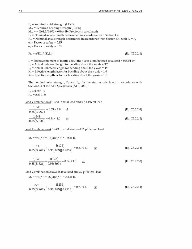
44 Commentary on AISI S230-07 w/S2-08
Pu = Required axial strength (LFRD) Mux = Required bending strength (LRFD) Mnx = = (664.5/0.95) = 699 ft-lb (Previously calculated) Pn = Nominal axial strength determined in accordance with Section C4. Pno = Nominal axial strength determined in accordance with Section C4, with Fn = Fy φc = Factor of safety = 0.85 φb = Factor of safety = 0.95 PEx = π2EIx / (KxLx)2 (Eq. C5.2.2-6) Ix = Effective moment of inertia about the x-axis at unfactored total load = 0.5051 in4 Lx = Actual unbraced length for bending about the x-axis = 96” Ly = Actual unbraced length for bending about the y-axis = 48” Kx = Effective length factor for buckling about the x-axis = 1.0 Ky = Effective length factor for buckling about the y-axis = 1.0
The nominal axial strength, Pn and Pno for the stud as calculated in accordance with Section C4 of the AISI Specification (AISI, 2001):
Pn = 3,267 lbs Pno = 5,631 lbs
Load Combination 3: 1,643 lb axial load and 0 plf lateral load
( )1,643
0.85 3, 267 = 0.59 < 1.0 ok (Eq. C5.2.2-1)
( )1,643
0.85 5,631 = 0.34 < 1.0 ok (Eq. C5.2.2-2)
Load Combination 4: 1,643 lb axial load and 16 plf lateral load
Mx = wL2/ 8 = (16)(8)2 / 8 = 128 ft-lb
( )( )
( )( )1 1281,643
0.85 3, 267 0.95 699 0.9052+ = 0.80 < 1.0 ok (Eq. C5.2.2-1)
( )( )
( )1 1281,643
0.85 5,631 0.95 699+ = 0.54 < 1.0 ok (Eq. C5.2.2-2)
Load Combination 5: 822 lb axial load and 32 plf lateral load
Mx = wL2/ 8 = (32)(8)2 / 8 = 256 ft-lb
( )( )
( )( )1 256822
0.85 3, 267 0.95 699 0.9516+ = 0.70 < 1.0 ok (Eq. C5.2.2-1)
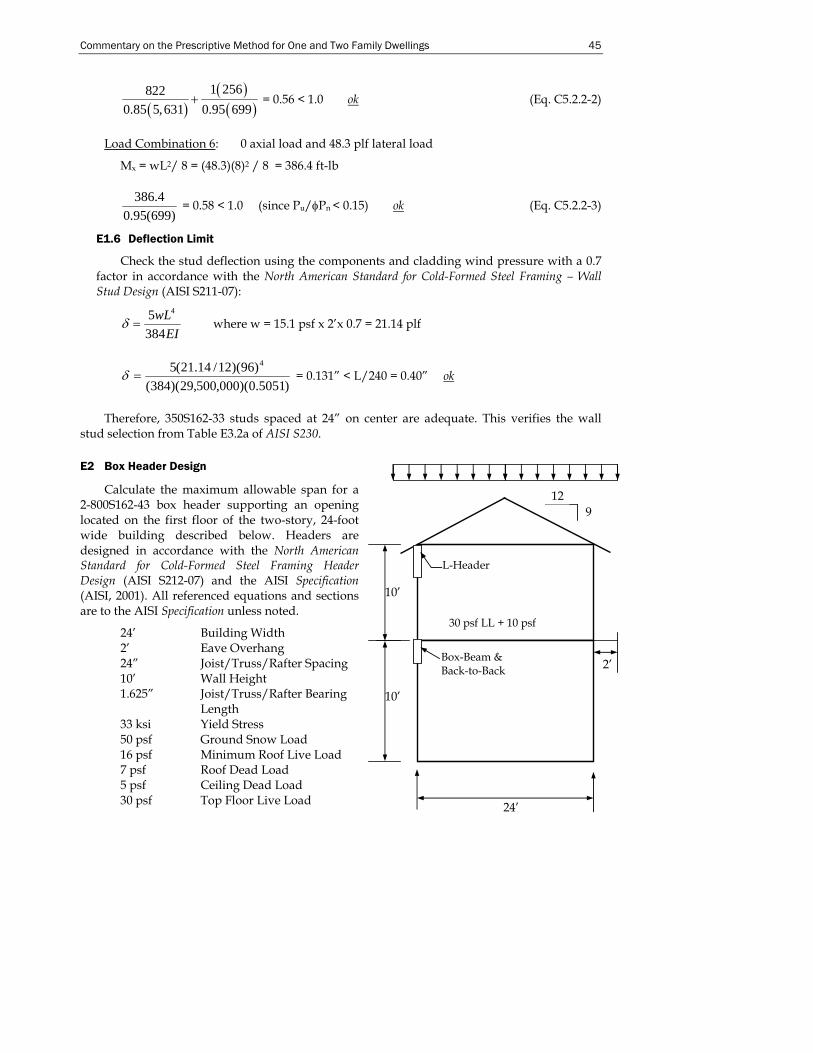
Commentary on the Prescriptive Method for One and Two Family Dwellings 45
( )( )
( )1 256822
0.85 5,631 0.95 699+ = 0.56 < 1.0 ok (Eq. C5.2.2-2)
Load Combination 6: 0 axial load and 48.3 plf lateral load
Mx = wL2/ 8 = (48.3)(8)2 / 8 = 386.4 ft-lb
386.40.95(699)
= 0.58 < 1.0 (since Pu/φPn < 0.15) ok (Eq. C5.2.2-3)
E1.6 Deflection Limit
Check the stud deflection using the components and cladding wind pressure with a 0.7 factor in accordance with the North American Standard for Cold-Formed Steel Framing – Wall Stud Design (AISI S211-07):
δ =5384
4wLEI
where w = 15.1 psf x 2’x 0.7 = 21.14 plf
)5051.0)(000,500,29)(384()96)(12/14.21(5 4
=δ = 0.131” < L/240 = 0.40” ok
Therefore, 350S162-33 studs spaced at 24” on center are adequate. This verifies the wall
stud selection from Table E3.2a of AISI S230.
E2 Box Header Design
Calculate the maximum allowable span for a 2-800S162-43 box header supporting an opening located on the first floor of the two-story, 24-foot wide building described below. Headers are designed in accordance with the North American Standard for Cold-Formed Steel Framing Header Design (AISI S212-07) and the AISI Specification (AISI, 2001). All referenced equations and sections are to the AISI Specification unless noted.
24’ Building Width 2’ Eave Overhang 24” Joist/Truss/Rafter Spacing 10’ Wall Height 1.625” Joist/Truss/Rafter Bearing
Length 33 ksi Yield Stress 50 psf Ground Snow Load 16 psf Minimum Roof Live Load 7 psf Roof Dead Load 5 psf Ceiling Dead Load 30 psf Top Floor Live Load
10’
24’
12 9
2’
10’
L-Header
Box-Beam & Back-to-Back
30 psf LL + 10 psf
46 Commentary on AISI S230-07 w/S2-08
10 psf Top Floor Dead Load L/240 Total Load Deflection Limit L/360 Live Load Deflection Limit 10 psf Wall Dead Load
E2.1 Design Loads
Dead Loads: Ceiling Dead Load = 5(24/2) = 60 plf Roof Dead Load = 7(28/2) = 98 plf Wall Dead Load = 10(10) = 100 plf Top Floor Dead Load = 10(24/2) = 120 plf Total Dead Load = 378 plf
Live Loads: Roof Live Load = 16(28/2) = 224 plf Balanced Snow Load = 0.7(50)(28/2) = 490 plf Unbalanced Snow Load = (50)(2 + 24/2)(0.75x24+2/2)/24 = 554 plf controls Top Floor Live Load = 30(24/2) = 360 plf
E2.2 Load Combinations
1. 1.4D = 1.4(378) = 529 plf 2. 1.2D + 1.6L + 0.5(Lr or S) = 1.2(378) + 1.6(360) + 0.5(554) = 1,306 plf 3. 1.2D + 0.5L + 1.6(Lr or S) = 1.2(378) + 0.5(360) + 1.6(554) = 1,520 plf controls
E2.3 Member Properties
d = 8.0” Depth of section t = 0.0451” Design thickness R = 0.09375” Inside bend radius Ixx = 9.00 in4 Moment of inertia for deflection
E2.4 Bending Capacity
Mn = 5,606 ft-lb Nominal flexural strength (calculated per Specification) φb = 0.95 Resistance factor for flexural strength (per Specification) φbMn = 5,326 ft-lb (Design strength for two sections with punched webs)
M = 8
2wL L = wM8 =
8(5,326)1,520
L = 5.29 ft = 5’-3”
E2.5 Deflection Limit
Δ = L/240 (total loads) The deflection equation for a simply supported span with distributed load is:
45384
wLEI
Δ = = L/240
L = 4384 ( / 240)
5xEI Lw
= ( )( )( )( )
3384 29,500,000 9.00
5 1, 292 /12 240= 7’-8”
Commentary on the Prescriptive Method for One and Two Family Dwellings 47
where: L = Single span length (inches)
Ix = Effective moment of inertia for deflection= 9.00 in4 w = 1292 plf E = Modulus of elasticity = 29,500,000 psi Deflection Limit = L/240 for total loads and L/360 for live loads,
inches
Δ = L/360 (live loads)
EIwL
3845 4
=Δ = L/360 L = ( )
3384(29,500,000)(9.00)
5 360 /12 360 = 10’-3”
where: w = 360 plf
E2.6 Shear Capacity
In accordance with Section C3.2 of the AISI S100 the nominal shear strength, Vn, is calculated to be 5144 lb for the box header. Use the design shear strength, φVn, to calculate the maximum unsupported span length.
2nwLVφ =
2 nVLwφ
=
where: w = required strength (factored uniform load) = 1,520 plf
( )( )2 0.95 5,1441,520
L = L = 6.43’ = 6’-5”
E2.7 Combined Bending and Web Crippling Capacity
In accordance with Section C3.4.1 of the AISI Specification, the nominal web crippling strength, Pn, is calculated to be 1983 lb for the box header assuming flanges are unfastened to the support and no reduction is required for the presence of web holes. Pn should be adjusted for presence of web holes in each of the C-section members in accordance with Section C3.4.2 of the AISI Specification (AISI, 2001). Check applicability of AISI Specification Section C3.4.2:
d0/h = 1.5/7.722 = 0.19 < 0.7 h/t = 7.722/0.0451 = 171.2 < 200 Holes centered at mid-depth of the web Clear distance between holes ≥ 18” Circular hole diameter ≤ 6” Non-circular holes, hole depth (d0) = 1.5” ≤ 2.5” and b = 4” ≤ 4.5” d0 > 9/16”
Rc = 0.90 – 0.047do/h + 0.053x/h ≤ 1.0 (Eq. C3.4.2-2)
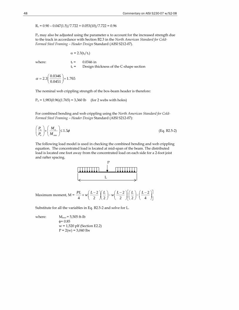
48 Commentary on AISI S230-07 w/S2-08
P
L
Rc = 0.90 – 0.047(1.5)/7.722 + 0.053(10)/7.722 = 0.96 Pn may also be adjusted using the parameter α to account for the increased strength due to the track in accordance with Section B2.3 in the North American Standard for Cold-Formed Steel Framing – Header Design Standard (AISI S212-07).
α = 2.3(tt/tc) where: tt = 0.0346 in
tc = Design thickness of the C-shape section
0.03462.3 1.7650.0451
α ⎛ ⎞= =⎜ ⎟⎝ ⎠
The nominal web crippling strength of the box-beam header is therefore: Pn = 1,983(0.96)(1.765) = 3,360 lb (for 2 webs with holes) For combined bending and web crippling using the North American Standard for Cold-Formed Steel Framing – Header Design Standard (AISI S212-07):
1.5u u
n nxo
P MP M
φ⎛ ⎞ ⎛ ⎞
+ ≤⎜ ⎟ ⎜ ⎟⎝ ⎠ ⎝ ⎠
(Eq. B2.5-2)
The following load model is used in checking the combined bending and web crippling equation. The concentrated load is located at mid-span of the beam. The distributed load is located one foot away from the concentrated load on each side for a 2-foot joist and rafter spacing.
Maximum moment, M = 2 2 2
4 2 2 2 2 4PL L L L L Lw w ⎡ ⎤− − −⎛ ⎞⎛ ⎞ ⎛ ⎞ ⎛ ⎞ ⎛ ⎞+ − −⎜ ⎟⎜ ⎟ ⎜ ⎟ ⎜ ⎟ ⎜ ⎟⎢ ⎥⎝ ⎠⎝ ⎠ ⎝ ⎠ ⎝ ⎠ ⎝ ⎠⎣ ⎦
Substitute for all the variables in Eq. B2.5-2 and solve for L. where: Mnxo = 5,505 ft-lb
φ= 0.85 w = 1,520 plf (Section E2.2) P = 2(w) = 3,040 lbs
Commentary on the Prescriptive Method for One and Two Family Dwellings 49
( )3,040 1.5 0.853,360 5,505
uM⎛ ⎞ ⎛ ⎞+ ≤⎜ ⎟ ⎜ ⎟
⎝ ⎠ ⎝ ⎠ 2,038uM = ft-lb
Set Mu = M = 2 2 2
4 2 2 2 2 4PL L L L L Lw w ⎡ ⎤− − −⎛ ⎞⎛ ⎞ ⎛ ⎞ ⎛ ⎞ ⎛ ⎞+ − −⎜ ⎟⎜ ⎟ ⎜ ⎟ ⎜ ⎟ ⎜ ⎟⎢ ⎥⎝ ⎠⎝ ⎠ ⎝ ⎠ ⎝ ⎠ ⎝ ⎠⎣ ⎦
Solving the above equation for L gives: L = 2.594 ft = 2’-7”
Therefore, the maximum span for a 2-800S162-43 header for the conditions in this example is 2’-7”. This confirms the maximum span given in Table E7.4a of AISI S230.
E3 Back-to-Back Header Design
Calculate the maximum allowable spans for a 2-800S162-43 back-to-back header supporting an opening located on the first floor of the two-story building described for the example in Section E2. All referenced equations and sections are to the Specification unless noted.
E3.1 Design Loads
Dead Loads: Ceiling Dead Load = 5(24/2) = 60 plf Roof Dead Load = 7(28/2) = 98 plf Wall Dead Load = 10(10) = 100 plf Top Floor Dead Load = 10(24/2) = 120 plf Total Dead Load = 378 plf
Live Loads: Roof Live Load = 16(28/2) = 224 plf Balanced Snow Load = 0.7(50)(28/2) = 490 plf Unbalanced Snow Load = (50)(2 + 24/2)(0.75x24+2/2)/24 = 554 plf controls Top Floor Live Load = 30(24/2) = 360 plf
E3.2 Load Combinations
1. 1.4D = 1.4(358) = 501 plf 2. 1.2D + 1.6L + 0.5(Lr or S) = 1.2(358) + 1.6(360) + 0.5(490) = 1,251 plf 3. 1.2D + 0.5L + 1.6(Lr or S) = 1.2(358) + 0.5(360) + 1.6(490) = 1,394 plf controls
E3.3 Member Properties
Same as previous example in E2.3
E3.4 Bending Capacity
Same as previous example in E2.4
E3.5 Deflection Limit
Same as previous example in E2.5
E3.6 Shear Capacity
Same as previous example in E2.6
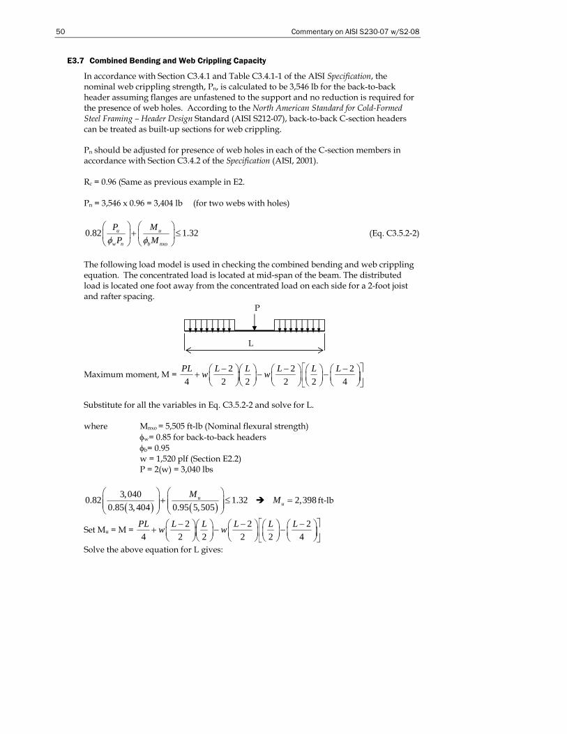
50 Commentary on AISI S230-07 w/S2-08
P
L
E3.7 Combined Bending and Web Crippling Capacity
In accordance with Section C3.4.1 and Table C3.4.1-1 of the AISI Specification, the nominal web crippling strength, Pn, is calculated to be 3,546 lb for the back-to-back header assuming flanges are unfastened to the support and no reduction is required for the presence of web holes. According to the North American Standard for Cold-Formed Steel Framing – Header Design Standard (AISI S212-07), back-to-back C-section headers can be treated as built-up sections for web crippling. Pn should be adjusted for presence of web holes in each of the C-section members in accordance with Section C3.4.2 of the Specification (AISI, 2001). Rc = 0.96 (Same as previous example in E2. Pn = 3,546 x 0.96 = 3,404 lb (for two webs with holes)
0.82 1.32u u
w n b nxo
P MP Mφ φ
⎛ ⎞ ⎛ ⎞+ ≤⎜ ⎟ ⎜ ⎟
⎝ ⎠ ⎝ ⎠ (Eq. C3.5.2-2)
The following load model is used in checking the combined bending and web crippling equation. The concentrated load is located at mid-span of the beam. The distributed load is located one foot away from the concentrated load on each side for a 2-foot joist and rafter spacing.
Maximum moment, M = 2 2 2
4 2 2 2 2 4PL L L L L Lw w ⎡ ⎤− − −⎛ ⎞⎛ ⎞ ⎛ ⎞ ⎛ ⎞ ⎛ ⎞+ − −⎜ ⎟⎜ ⎟ ⎜ ⎟ ⎜ ⎟ ⎜ ⎟⎢ ⎥⎝ ⎠⎝ ⎠ ⎝ ⎠ ⎝ ⎠ ⎝ ⎠⎣ ⎦
Substitute for all the variables in Eq. C3.5.2-2 and solve for L. where Mnxo = 5,505 ft-lb (Nominal flexural strength)
φw= 0.85 for back-to-back headers φb= 0.95 w = 1,520 plf (Section E2.2) P = 2(w) = 3,040 lbs
( ) ( )3,0400.82 1.32
0.85 3, 404 0.95 5,505uM⎛ ⎞ ⎛ ⎞
+ ≤⎜ ⎟ ⎜ ⎟⎜ ⎟ ⎜ ⎟⎝ ⎠ ⎝ ⎠
2,398uM = ft-lb
Set Mu = M = 2 2 2
4 2 2 2 2 4PL L L L L Lw w ⎡ ⎤− − −⎛ ⎞⎛ ⎞ ⎛ ⎞ ⎛ ⎞ ⎛ ⎞+ − −⎜ ⎟⎜ ⎟ ⎜ ⎟ ⎜ ⎟ ⎜ ⎟⎢ ⎥⎝ ⎠⎝ ⎠ ⎝ ⎠ ⎝ ⎠ ⎝ ⎠⎣ ⎦
Solve the above equation for L gives:
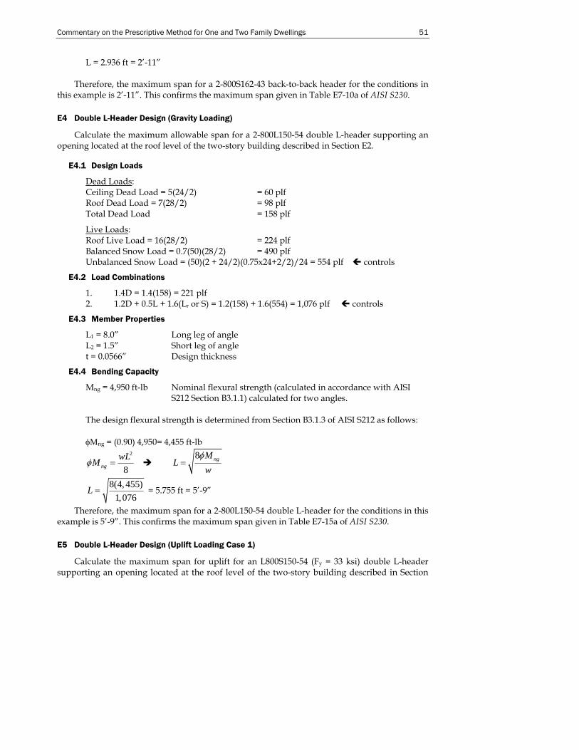
Commentary on the Prescriptive Method for One and Two Family Dwellings 51
L = 2.936 ft = 2’-11”
Therefore, the maximum span for a 2-800S162-43 back-to-back header for the conditions in this example is 2’-11”. This confirms the maximum span given in Table E7-10a of AISI S230.
E4 Double L-Header Design (Gravity Loading)
Calculate the maximum allowable span for a 2-800L150-54 double L-header supporting an opening located at the roof level of the two-story building described in Section E2.
E4.1 Design Loads
Dead Loads: Ceiling Dead Load = 5(24/2) = 60 plf Roof Dead Load = 7(28/2) = 98 plf Total Dead Load = 158 plf
Live Loads: Roof Live Load = 16(28/2) = 224 plf Balanced Snow Load = 0.7(50)(28/2) = 490 plf Unbalanced Snow Load = (50)(2 + 24/2)(0.75x24+2/2)/24 = 554 plf controls
E4.2 Load Combinations
1. 1.4D = 1.4(158) = 221 plf 2. 1.2D + 0.5L + 1.6(Lr or S) = 1.2(158) + 1.6(554) = 1,076 plf controls
E4.3 Member Properties
L1 = 8.0” Long leg of angle L2 = 1.5” Short leg of angle t = 0.0566” Design thickness
E4.4 Bending Capacity
Mng = 4,950 ft-lb Nominal flexural strength (calculated in accordance with AISI S212 Section B3.1.1) calculated for two angles.
The design flexural strength is determined from Section B3.1.3 of AISI S212 as follows: φΜng = (0.90) 4,950= 4,455 ft-lb
2
8ngwLMφ =
8 ngML
wφ
=
8(4, 455)1,076
L = = 5.755 ft = 5’-9”
Therefore, the maximum span for a 2-800L150-54 double L-header for the conditions in this example is 5’-9”. This confirms the maximum span given in Table E7-15a of AISI S230.
E5 Double L-Header Design (Uplift Loading Case 1)
Calculate the maximum span for uplift for an L800S150-54 (Fy = 33 ksi) double L-header supporting an opening located at the roof level of the two-story building described in Section
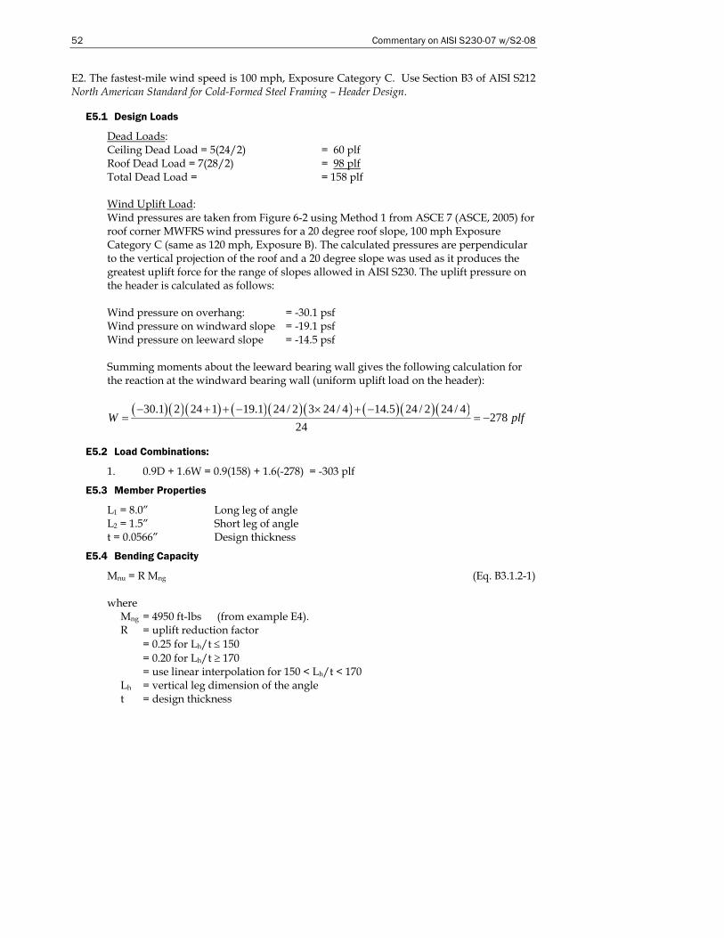
52 Commentary on AISI S230-07 w/S2-08
E2. The fastest-mile wind speed is 100 mph, Exposure Category C. Use Section B3 of AISI S212 North American Standard for Cold-Formed Steel Framing – Header Design.
E5.1 Design Loads
Dead Loads: Ceiling Dead Load = 5(24/2) = 60 plf Roof Dead Load = 7(28/2) = 98 plf Total Dead Load = = 158 plf Wind Uplift Load: Wind pressures are taken from Figure 6-2 using Method 1 from ASCE 7 (ASCE, 2005) for roof corner MWFRS wind pressures for a 20 degree roof slope, 100 mph Exposure Category C (same as 120 mph, Exposure B). The calculated pressures are perpendicular to the vertical projection of the roof and a 20 degree slope was used as it produces the greatest uplift force for the range of slopes allowed in AISI S230. The uplift pressure on the header is calculated as follows: Wind pressure on overhang: = -30.1 psf Wind pressure on windward slope = -19.1 psf Wind pressure on leeward slope = -14.5 psf Summing moments about the leeward bearing wall gives the following calculation for the reaction at the windward bearing wall (uniform uplift load on the header):
( )( )( ) ( )( )( ) ( )( )( )30.1 2 24 1 19.1 24 / 2 3 24 / 4 14.5 24 / 2 24 / 4278
24W plf
− + + − × + −= = −
E5.2 Load Combinations:
1. 0.9D + 1.6W = 0.9(158) + 1.6(-278) = -303 plf
E5.3 Member Properties
L1 = 8.0” Long leg of angle L2 = 1.5” Short leg of angle t = 0.0566” Design thickness
E5.4 Bending Capacity
Mnu = R Mng (Eq. B3.1.2-1) where
Mng = 4950 ft-lbs (from example E4). R = uplift reduction factor = 0.25 for Lh/t ≤ 150 = 0.20 for Lh/t ≥ 170 = use linear interpolation for 150 < Lh/t < 170 Lh = vertical leg dimension of the angle t = design thickness

Commentary on the Prescriptive Method for One and Two Family Dwellings 53
For LRFD, calculate the design flexural strength for uplift: Lh/t = 8.0/0.0566 = 141.3 ≤ 150, Therefore, R = 0.25 Mnu = 0.25(4,950) = 1,238 ft-lb Mu ≤ φMnu (Eq. B3.1.3-4) Calculate the maximum span for uplift: φ = 0.80
2
8nuwLMφ =
8 nuMLw
φ=
8(0.8)(1, 238)303
L = = 5.114’ = 5’-2”
Therefore, the maximum span for a 2-800L150-54 double L-header for the conditions in this
example is 5’-2”. This confirms the maximum span given in Table E7-20a of AISI S230.
E6 Double L-Header Design (Uplift Loading Case 2)
Calculate the maximum span for a 2-L800S150-54 L-header located in the first story of a the two-story building described in Section F1, subjected to 110 mph Exposure Category C wind speed.
E6.1 Design Loads
Dead Loads: Ceiling Dead Load = 5(24/2) = 60 plf Roof Dead Load = 7(28)/2 = 98 plf Floor Dead Load = 10(24/2) = 120 plf Wall Dead Load = 10(10) = 100* plf Total Dead Load = 378 plf
* Note: Use 10’ high wall which is the maximum allowed by AISI S230
Wind Uplift Load: Wind pressures are taken from Figure 6-2 using Method 1 from ASCE 7 (ASCE, 2005) for roof corner MWFRS wind pressures for a 20 degree roof slope, 110 mph Exposure Category C (same as 130 mph, Exposure B). The calculated pressures are perpendicular to the vertical projection of the roof and a 20 degree slope was used as it produces the greatest uplift force for the range of slopes allowed in AISI S230. The uplift pressure on the header is calculated as follows: Wind pressure on overhang: = -35.4 psf Wind pressure on windward slope = -22.4 psf Wind pressure on leeward slope = -17.1 psf
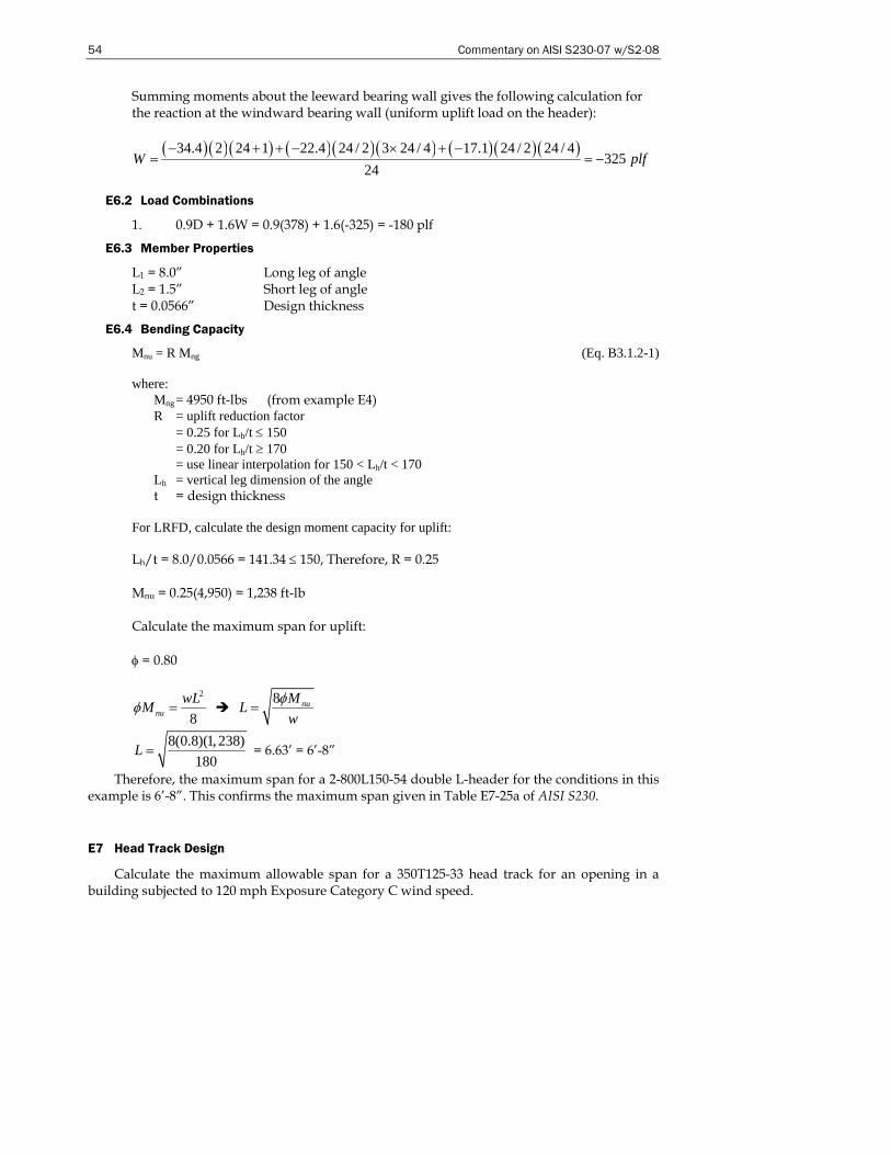
54 Commentary on AISI S230-07 w/S2-08
Summing moments about the leeward bearing wall gives the following calculation for the reaction at the windward bearing wall (uniform uplift load on the header):
( )( )( ) ( )( )( ) ( )( )( )34.4 2 24 1 22.4 24 / 2 3 24 / 4 17.1 24 / 2 24 / 4325
24W plf
− + + − × + −= = −
E6.2 Load Combinations
1. 0.9D + 1.6W = 0.9(378) + 1.6(-325) = -180 plf
E6.3 Member Properties
L1 = 8.0” Long leg of angle L2 = 1.5” Short leg of angle t = 0.0566” Design thickness
E6.4 Bending Capacity
Mnu = R Mng (Eq. B3.1.2-1) where:
Mng = 4950 ft-lbs (from example E4) R = uplift reduction factor = 0.25 for Lh/t ≤ 150 = 0.20 for Lh/t ≥ 170 = use linear interpolation for 150 < Lh/t < 170 Lh = vertical leg dimension of the angle t = design thickness
For LRFD, calculate the design moment capacity for uplift: Lh/t = 8.0/0.0566 = 141.34 ≤ 150, Therefore, R = 0.25 Mnu = 0.25(4,950) = 1,238 ft-lb Calculate the maximum span for uplift: φ = 0.80
2
8nuwLMφ =
8 nuMLw
φ=
8(0.8)(1, 238)180
L = = 6.63’ = 6’-8”
Therefore, the maximum span for a 2-800L150-54 double L-header for the conditions in this example is 6’-8”. This confirms the maximum span given in Table E7-25a of AISI S230.
E7 Head Track Design
Calculate the maximum allowable span for a 350T125-33 head track for an opening in a building subjected to 120 mph Exposure Category C wind speed.
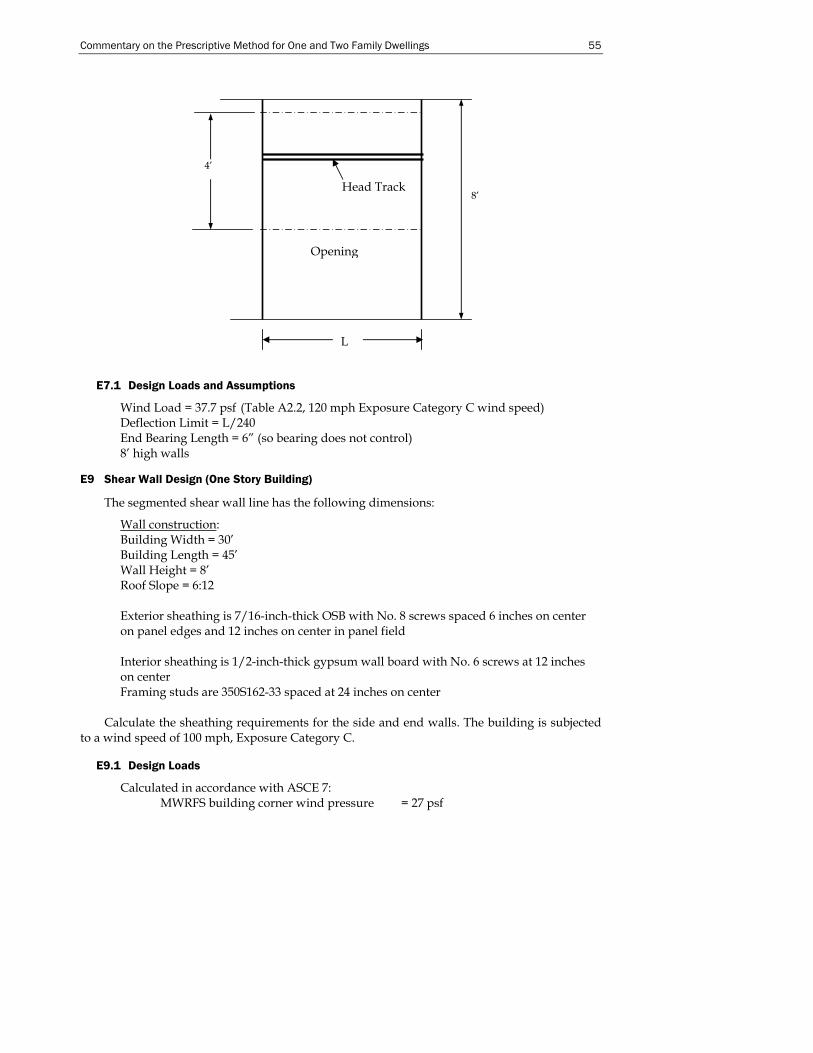
Commentary on the Prescriptive Method for One and Two Family Dwellings 55
E7.1 Design Loads and Assumptions
Wind Load = 37.7 psf (Table A2.2, 120 mph Exposure Category C wind speed) Deflection Limit = L/240 End Bearing Length = 6” (so bearing does not control) 8’ high walls
E9 Shear Wall Design (One Story Building)
The segmented shear wall line has the following dimensions:
Wall construction: Building Width = 30’ Building Length = 45’ Wall Height = 8’ Roof Slope = 6:12 Exterior sheathing is 7/16-inch-thick OSB with No. 8 screws spaced 6 inches on center on panel edges and 12 inches on center in panel field Interior sheathing is 1/2-inch-thick gypsum wall board with No. 6 screws at 12 inches on center Framing studs are 350S162-33 spaced at 24 inches on center
Calculate the sheathing requirements for the side and end walls. The building is subjected to a wind speed of 100 mph, Exposure Category C.
E9.1 Design Loads
Calculated in accordance with ASCE 7: MWRFS building corner wind pressure = 27 psf
8’
4’
Head Track
Opening
L
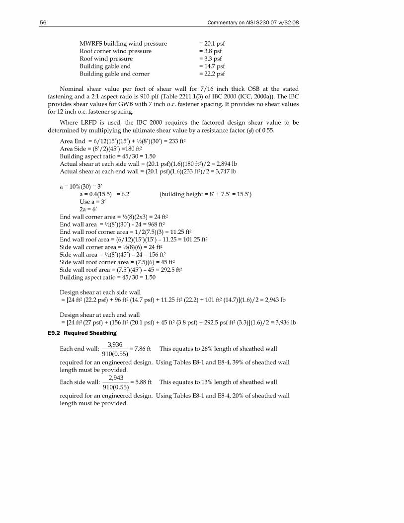
56 Commentary on AISI S230-07 w/S2-08
MWRFS building wind pressure = 20.1 psf Roof corner wind pressure = 3.8 psf Roof wind pressure = 3.3 psf Building gable end = 14.7 psf Building gable end corner = 22.2 psf
Nominal shear value per foot of shear wall for 7/16 inch thick OSB at the stated
fastening and a 2:1 aspect ratio is 910 plf (Table 2211.1(3) of IBC 2000 (ICC, 2000a)). The IBC provides shear values for GWB with 7 inch o.c. fastener spacing. It provides no shear values for 12 inch o.c. fastener spacing.
Where LRFD is used, the IBC 2000 requires the factored design shear value to be determined by multiplying the ultimate shear value by a resistance factor (φ) of 0.55.
Area End = 6/12(15’)(15’) + ½(8’)(30’) = 233 ft2 Area Side = (8’/2)(45’) =180 ft2 Building aspect ratio = 45/30 = 1.50 Actual shear at each side wall = (20.1 psf)(1.6)(180 ft2)/2 = 2,894 lb Actual shear at each end wall = (20.1 psf)(1.6)(233 ft2)/2 = 3,747 lb a = 10%(30) = 3’ a = 0.4(15.5) = 6.2’ (building height = 8’ + 7.5’ = 15.5’)
Use a = 3’ 2a = 6’
End wall corner area = ½(8)(2x3) = 24 ft2 End wall area = ½(8’)(30’) - 24 = 968 ft2 End wall roof corner area = 1/2(7.5)(3) = 11.25 ft2 End wall roof area = (6/12)(15’)(15’) – 11.25 = 101.25 ft2 Side wall corner area = ½(8)(6) = 24 ft2 Side wall area = ½(8’)(45’) – 24 = 156 ft2 Side wall roof corner area = (7.5)(6) = 45 ft2 Side wall roof area = (7.5’)(45’) – 45 = 292.5 ft2 Building aspect ratio = 45/30 = 1.50 Design shear at each side wall = [24 ft2 (22.2 psf) + 96 ft2 (14.7 psf) + 11.25 ft2 (22.2) + 101 ft2 (14.7)](1.6)/2 = 2,943 lb Design shear at each end wall = [24 ft2 (27 psf) + (156 ft2 (20.1 psf) + 45 ft2 (3.8 psf) + 292.5 psf ft2 (3.3)](1.6)/2 = 3,936 lb
E9.2 Required Sheathing
Each end wall: )55.0(910
936,3= 7.86 ft This equates to 26% length of sheathed wall
required for an engineered design. Using Tables E8-1 and E8-4, 39% of sheathed wall length must be provided.
Each side wall: )55.0(910
943,2= 5.88 ft This equates to 13% length of sheathed wall
required for an engineered design. Using Tables E8-1 and E8-4, 20% of sheathed wall length must be provided.
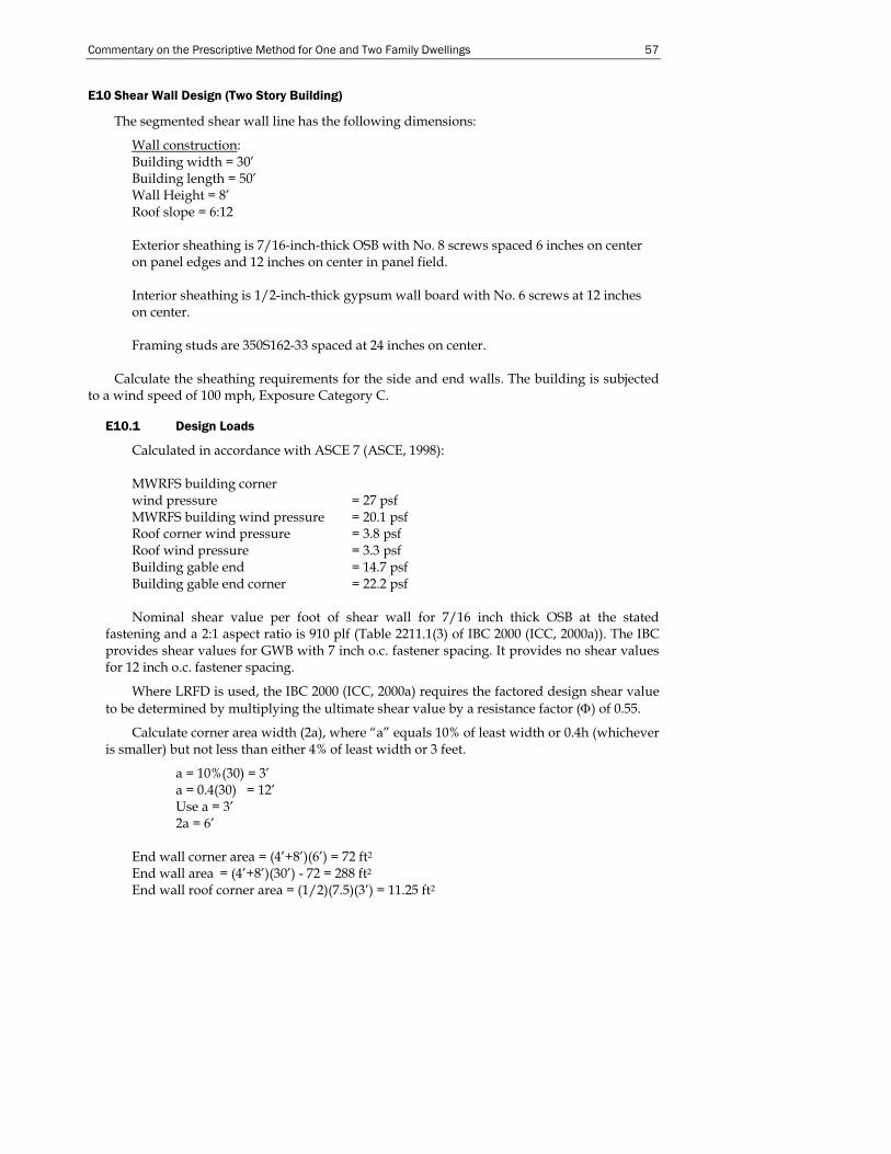
Commentary on the Prescriptive Method for One and Two Family Dwellings 57
E10 Shear Wall Design (Two Story Building)
The segmented shear wall line has the following dimensions:
Wall construction: Building width = 30’ Building length = 50’ Wall Height = 8’ Roof slope = 6:12 Exterior sheathing is 7/16-inch-thick OSB with No. 8 screws spaced 6 inches on center on panel edges and 12 inches on center in panel field. Interior sheathing is 1/2-inch-thick gypsum wall board with No. 6 screws at 12 inches on center. Framing studs are 350S162-33 spaced at 24 inches on center.
Calculate the sheathing requirements for the side and end walls. The building is subjected to a wind speed of 100 mph, Exposure Category C.
E10.1 Design Loads
Calculated in accordance with ASCE 7 (ASCE, 1998): MWRFS building corner wind pressure = 27 psf MWRFS building wind pressure = 20.1 psf Roof corner wind pressure = 3.8 psf Roof wind pressure = 3.3 psf Building gable end = 14.7 psf Building gable end corner = 22.2 psf Nominal shear value per foot of shear wall for 7/16 inch thick OSB at the stated
fastening and a 2:1 aspect ratio is 910 plf (Table 2211.1(3) of IBC 2000 (ICC, 2000a)). The IBC provides shear values for GWB with 7 inch o.c. fastener spacing. It provides no shear values for 12 inch o.c. fastener spacing.
Where LRFD is used, the IBC 2000 (ICC, 2000a) requires the factored design shear value to be determined by multiplying the ultimate shear value by a resistance factor (Φ) of 0.55.
Calculate corner area width (2a), where “a” equals 10% of least width or 0.4h (whichever is smaller) but not less than either 4% of least width or 3 feet.
a = 10%(30) = 3’ a = 0.4(30) = 12’ Use a = 3’ 2a = 6’
End wall corner area = (4’+8’)(6’) = 72 ft2 End wall area = (4’+8’)(30’) - 72 = 288 ft2 End wall roof corner area = (1/2)(7.5)(3’) = 11.25 ft2

58 Commentary on AISI S230-07 w/S2-08
End wall roof area = (6/12)(15’)(15’) – 11.25 = 101 ft2 Side wall corner area = (4’+8’)(6’) = 72 ft2 Side wall area = (4’+8’)(50’) – 72 = 528 ft2 Side wall roof corner area = (1/2)(7.5)(6)(2) = 45 ft2 Side wall roof area = (7.5’)(50’) – 45 = 330 ft2 Building aspect ratio = 50/30 = 1.67 Design shear at each side wall = [72 ft2 (22.2 psf)+288 ft2 (14.7psf)+11.25 ft2 (22.2 psf)+101 ft2 (14.7 psf)](1.6)/2 = 5,954 lb Design shear at each end wall = [72 ft2 (27 psf) + (528 ft2 (20.1psf) + 22.5 ft2 (3.8 psf) + 330 ft2 (3.3psf)](1.6)/2 = 10,985 lb
E10.2 Required Sheathing (First Floor Walls)
Each end wall: )55.0(910
985,10= 21.95 ft This equates to 73% of length of sheathed wall
required for an engineered design. Using Tables E8-1 and E8-4, 97% of sheathed wall length must be provided.
Each side wall: )55.0(910
954,5= 11.90 ft This equates to 24% of side wall length of sheathed
wall required for an engineered design. Using Tables E8-1 and E8-4, 35% of sheathed wall length must be provided.
E11 Shear Wall Design (High Seismic Area)
Design the lateral force resisting system for the example building shown below. Use Type I braced wall for the side walls and Type II braced walls for the end walls.
E11.1 Design Assumptions
Building Width = 30’ Building Length = 50’ Roof Slope = 6:12 Seismic Design Category = D2 Roof Dead Load = 15 psf Exterior Wall Dead Load = 7 psf Ground Snow Load = 25 psf Slab-on-grade foundation Interior Wall Dead Load = 5 psf Overhang = 2 ft Studs: 350S162-33 Stud Spacing = 16” on center
E11.2 Design Loads
Roof Dead Load = 15 psf Floor Dead Load = 10 psf Exterior Wall Dead Loads = 7 psf
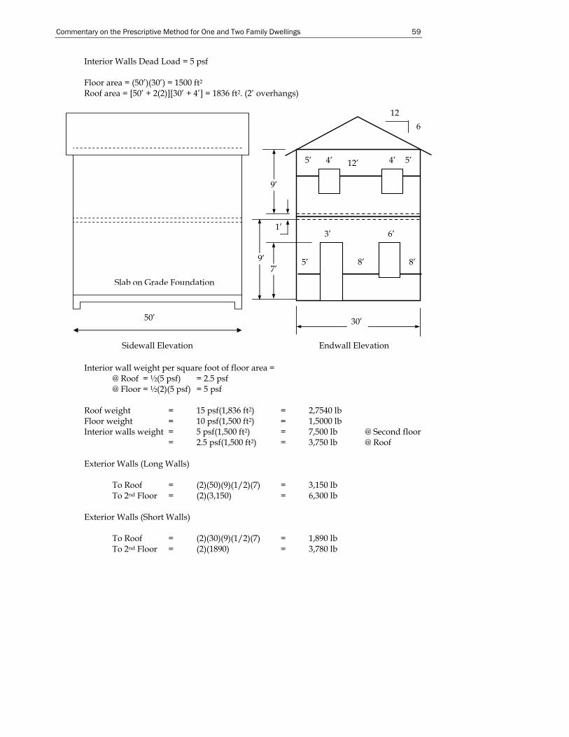
Commentary on the Prescriptive Method for One and Two Family Dwellings 59
Interior Walls Dead Load = 5 psf Floor area = (50’)(30’) = 1500 ft2 Roof area = [50’ + 2(2)][30’ + 4’] = 1836 ft2. (2’ overhangs)
Interior wall weight per square foot of floor area = @ Roof = ½(5 psf) = 2.5 psf @ Floor = ½(2)(5 psf) = 5 psf Roof weight = 15 psf(1,836 ft2) = 2,7540 lb Floor weight = 10 psf(1,500 ft2) = 1,5000 lb Interior walls weight = 5 psf(1,500 ft2) = 7,500 lb @ Second floor = 2.5 psf(1,500 ft2) = 3,750 lb @ Roof Exterior Walls (Long Walls) To Roof = (2)(50)(9)(1/2)(7) = 3,150 lb To 2nd Floor = (2)(3,150) = 6,300 lb Exterior Walls (Short Walls) To Roof = (2)(30)(9)(1/2)(7) = 1,890 lb To 2nd Floor = (2)(1890) = 3,780 lb
50’
Sidewall Elevation
Slab on Grade Foundation
1’
Endwall Elevation
12 6
9’
9’
30’
4’ 5’ 5’ 4’
5’
6’
8’
3’
8’
12’
7’

60 Commentary on AISI S230-07 w/S2-08
Total Load at Roof = 3,150 + 1,890 = 5,040 lb Total Load at 2nd Floor= 6,300 + 3,780 = 10,080 lb Sum of Weights For Base Shear, Vertical Distribution and Shear Wall Design: At Roof: 27,540 + 3,750 + 5,040 = 36,330 lb At 2nd Floor: 15,000 + 7,500 + 10,080 = 32,580 lb Sum: 36,330 + 32,580 = 68,910 lb For Diaphragm Design PRoof = 36,330 – 3,150 = 33,180 lb P2nd Floor = 32,580 – 6,300 = 26,280 lb PRoof = 36,330 – 1,890 = 34,440 lb P2nd Floor = 32,580 – 3,780 = 28,800 lb Determine Base Shear – SDC D2 Base Shear, V = CsW (IBC Eq. 16-34) Cs = SDS/R SDS = 1.17 (IRC Table R301.2.2.1.1) R = 6 (IBC Table 1617.6, System 1-K) Cs = 1.17/6 = 0.195 V = (0.195)(68,910) = 13,437 lb Vertical Distribution Fx = CvxV (IBC Eq. 16-41)
Cvx=
∑=
n
iii
xx
HW
HW
1
(IBC Eq. 16-42 with K = 1)
Vx = ∑=
n
IiF
1
(IBC Eq. 16-43)
Height2nd = 9’ + 1’ = 10 ft HeightRoof = (2)(9) + 1 + ½(7.5’) = 22.75 ft
30’
50’
P
30’
P
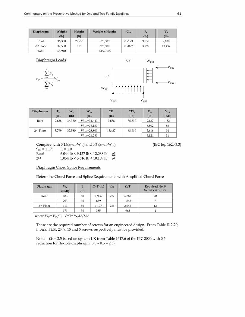
Commentary on the Prescriptive Method for One and Two Family Dwellings 61
Diaphragm Weight
(lb) Height
(ft) Weight x Height Cvx Fx
(lb) Vx
(lb) Roof 36,330 22.75’ 826,508 0.7173 9,638 9,638
2nd Floor 32,580 10’ 325,800 0.2827 3,799 13,437 Total 68,910 1,152,308
Diaphragm Loads
Fpx = pxn
xii
n
xix
WW
F
∑
∑
=
=
Diaphragm Fx
(lb) Wx
(lb) Wpx (lb)
ΣFi (lb)
ΣWi (lb)
Fpx
(lb) Vpx
(lb/ft) Wpx1=34,440 9,137 152 Roof 9,638 36,330 Wpx2=33,180
9,638 36,330 8,802 88
Wpx1=28,800 5,616 94 2nd Floor 3,799 32,580 Wpx2=26,280
13,437 68,910 5,124 51
Compare with 0.15(SDS IEWpx) and 0.3 (SDS IEWpx) (IBC Eq. 1620.3.3) SDS = 1.17; IE = 1.0 Roof 6,044 lb < 9,137 lb < 12,088 lb ok 2nd 5,054 lb < 5,616 lb < 10,109 lb ok Diaphragm Chord Splice Requirements Determine Chord Force and Splice Requirements with Amplified Chord Force
Diaphragm Wp
(lb/ft) L
(ft) C=T (lb) Ω0 Ω0T Required No. 8
Screws @ Splice
Roof 183 50 1,906 4,765 20 293 30 659
2.5 1,648 7
2nd Floor 113 50 1,177 2,943 12 171 30 385
2.5 963 4
where Wp = Fpx/L; C=T= WpL2/8L2 These are the required number of screws for an engineered design. From Table E12-20, in AISI S230, 23, 9, 15 and 5 screws respectively must be provided. Note: Ω0 = 2.5 based on system 1.K from Table 1617.6 of the IBC 2000 with 0.5 reduction for flexible diaphragm (3.0 – 0.5 = 2.5)
50’ Wpx2
30’
Wpx1
Vpx2
Vpx2
Vpx1 Vpx1
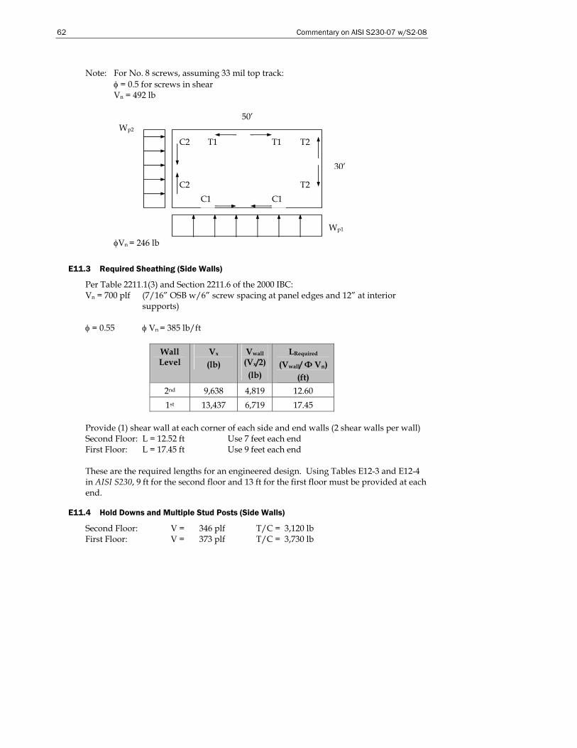
62 Commentary on AISI S230-07 w/S2-08
Note: For No. 8 screws, assuming 33 mil top track: φ = 0.5 for screws in shear Vn = 492 lb
φVn = 246 lb
E11.3 Required Sheathing (Side Walls)
Per Table 2211.1(3) and Section 2211.6 of the 2000 IBC: Vn = 700 plf (7/16” OSB w/6” screw spacing at panel edges and 12” at interior
supports) φ = 0.55 φ Vn = 385 lb/ft
Wall Level
Vx (lb)
Vwall
(Vx/2) (lb)
LRequired
(Vwall/ Φ Vn) (ft)
2nd 9,638 4,819 12.60 1st 13,437 6,719 17.45
Provide (1) shear wall at each corner of each side and end walls (2 shear walls per wall) Second Floor: L = 12.52 ft Use 7 feet each end First Floor: L = 17.45 ft Use 9 feet each end These are the required lengths for an engineered design. Using Tables E12-3 and E12-4 in AISI S230, 9 ft for the second floor and 13 ft for the first floor must be provided at each end.
E11.4 Hold Downs and Multiple Stud Posts (Side Walls)
Second Floor: V = 346 plf T/C = 3,120 lb First Floor: V = 373 plf T/C = 3,730 lb
50’
30’
Wp1
Wp2
C1
C2
C2 T2
T2 T1 T1
C1
Commentary on the Prescriptive Method for One and Two Family Dwellings 63
Multiple Studs Required at Shear Wall Ends Second Floor: Pu = 3,120 lb First Floor: Pu = 6,850 lb (when chords align) First Floor: Pu = 3,730 lb (when chords do not align) Allowable loads: (2) 350S162-33: φPn = 4,945 lb φPn = 4,945 lb > 3,730 lb (2) 350S162-54: φPn = 8,102 lb φPn = 8,102 lb > 6,850 lb These are the multiple studs for an engineered design. Using Table E12-19, 54 mil studs are not an option, therefore the AISI 230 would not apply for this design. Hold Downs Required at Shear Wall Ends Single Shear Wall: Tu = 3,730 lbs TASD = 2,710 lb Aligning Shear Walls: Tu = 6,850 lbs TASD = 4,893 lb Using a Hold Down with 5/8” diameter bolt for single shear wall: Tallowable = 5,260 lbs Tallowable = 3,950 lbs (without 1/3 increase for wind/seismic) Tallowable > TASD = 2,710 lb Using Hold Down with 5/8” diameter bolt for aligning shear wall: Tallowable = 7,920 lbs Tallowable = 5,940 lbs (without 1/3 increase for wind/seismic) Tallowable > TASD = 4,940 lb
E11.5 Required Sheathing (End Walls)
End wall shear walls use 7/16” OSB fastened with No. 8 screws at 6” at panel edges and 12” at intermediate supports. Per previous calculations, LRequired at 2nd floor = 12.6’; and LRequired at 1st floor = 17.45’. Try Type II walls (perforated shear wall): Determine percentage of fully sheathed wall @ 2nd floor = (5+12+5)/30 = 0.73 = 73.3% @ 1st floor = (5+8+8)/30 = 0.70 = 70% Maximum unrestrained opening at 1st and 2nd floor = 7’, with wall fully sheathed above and below. Interpolate for length adjustment factor from Table E11-2 for both “Percent Fully Sheathed Wall” and “Maximum Unrestrained Opening Height”:
64 Commentary on AISI S230-07 w/S2-08
At 2nd Floor:
% Fully Sheathed 6.75’ 7’ 7.5’ 60 1.28 1.32
73.3 1.176 1.182 1.203 80 1.12 1.14
Therefore, the required length of fully sheathed (Type II) wall = (1.182)(12.60’) = 14.89’ 14.89’ < 22’ provided by the full height sheathing for the upper wall. ok At 1st Floor:
% Fully Sheathed 6.75’ 7’ 7.5’ 60 1.28 1.293 1.32 70 1.2 1.21 1.23 80 1.12 1.127 1.14
Therefore, the required length of fully sheathed (Type II) wall = (1.21)(17.45’) = 21.11’ 21.11’ is close to 21’ provided by the full height sheathing for the lower wall. ok
E11.6 Hold Downs and Multiple Stud Posts (End Walls)
Second Floor: V = 162 plf T/C = 1,460 lb (when chords do not align) First Floor: V = 228 plf T/C = 3,730 lb (when chords align) Allowable loads: (2) 350S162-33: φPn = 4,945 lb φPn = 4,945 > 3,730 lb ok Hold Downs Required at Shear Wall Ends Single Shear Wall: Tu = 1,460 lbs TASD = 1,040 lb Aligning Shear Walls: Tu = 3,730 lbs TASD = 2,670 lb Using a Hold Down with 5/8” diameter bolt. For single shear walls: Tallowable = 5,260 lbs Tallowable = 3,950 lbs (without 1/3 increase for wind/seismic) Tallowable > TASD = 1,040 lb These are the multiple studs and hold down requirements for an engineered design. Use Table E12-17 to determine the chord strength and hold down strength required for this design. Determination of Top Track Requirements to Accommodate Diaphragm Chord Forces From the above, @Roof Cmax = 1,906 lb @2nd Floor Cmax = 1,177 lb
Commentary on the Prescriptive Method for One and Two Family Dwellings 65
Using computer software, the maximum axial capacity of a 350T125-33 (top track) is 2,882 lbs (concentric load with no weak axis bracing and a maximum track length of 1.33 ft). For L = 16” with track considered fully braced, φPn = 2,882 lb > 1,906 lb Note: The diaphragm chord forces were tabulated for the various roof and wall height combinations at various diaphragm spans with some breakdown of diaphragm aspect ratios where warranted. Establish Shear Anchor Requirements Based on Shear Wall Edge Screw Spacing Use shear wall capacity, based on shear wall edge screw spacing (6” o.c. at panel edges) to determine required shear anchor capacity: φVn = 385 plf @ 6” panel edge screw spacing Check 350T125-33 bottom track with nested 350S162-33 stud: φPn(Track) = 2,420 lb bearing capacity of track plus stud (Table E3.3-2) where: Fu = 45 ksi
t = 0.0346” d = 0.5” φ = 0.7 (Table E3.3-2)
φPn = 3,444 lb shear capacity of ½” diameter bolt (Eq. E3.4-1) where: Ab = 0.196 in2
Fnv = 27 ksi (Table E3.4-1) φ = 0.65 (Table E3.4-1)
Required Fastener Spacing = 2,420/385 = 6.28 feet This is the fastener spacing for an engineered design. Using Table E12-18, the required spacing is 5.0 feet.
E11.7 Continuous Strap for Drag Force
A. Tensile Capacity of 2.5” x 43-mil Strap
φTn = (0.95)(33 ksi)(2.5”)(0.0451”) = 3.535 kips Where: Fy = 33 ksi An = 0.113 in2 φ = 0.95
B. Screw Shear Capacity for Strap End Connections:
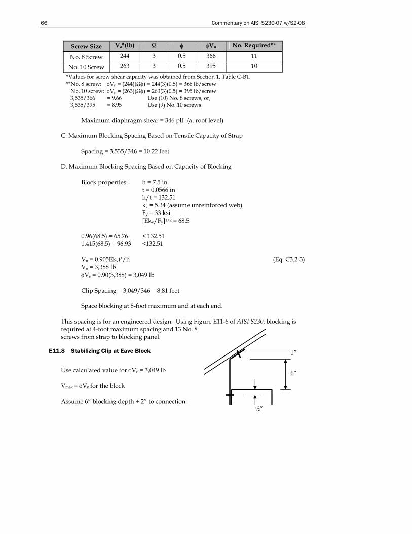
66 Commentary on AISI S230-07 w/S2-08
6”
1”
½”
Screw Size Va*(lb) Ω φ φVn No. Required**
No. 8 Screw 244 3 0.5 366 11
No. 10 Screw 263 3 0.5 395 10 *Values for screw shear capacity was obtained from Section 1, Table C-B1. **No. 8 screw: φVn = (244)(Ωφ) = 244(3)(0.5) = 366 lb/screw No. 10 screw: φVn = (263)(Ωφ) = 263(3)(0.5) = 395 lb/screw 3,535/366 = 9.66 Use (10) No. 8 screws, or, 3,535/395 = 8.95 Use (9) No. 10 screws
Maximum diaphragm shear = 346 plf (at roof level)
C. Maximum Blocking Spacing Based on Tensile Capacity of Strap Spacing = 3,535/346 = 10.22 feet
D. Maximum Blocking Spacing Based on Capacity of Blocking Block properties: h = 7.5 in
t = 0.0566 in h/t = 132.51 kv = 5.34 (assume unreinforced web) Fy = 33 ksi [Ekv/Fy]1/2 = 68.5
0.96(68.5) = 65.76 < 132.51 1.415(68.5) = 96.93 <132.51 Vn = 0.905Ekvt3/h (Eq. C3.2-3) Vn = 3,388 lb φVn = 0.90(3,388) = 3,049 lb Clip Spacing = 3,049/346 = 8.81 feet Space blocking at 8-foot maximum and at each end.
This spacing is for an engineered design. Using Figure E11-6 of AISI S230, blocking is required at 4-foot maximum spacing and 13 No. 8 screws from strap to blocking panel.
E11.8 Stabilizing Clip at Eave Block
Use calculated value for φVn = 3,049 lb Vmax = φVn for the block Assume 6” blocking depth + 2” to connection:
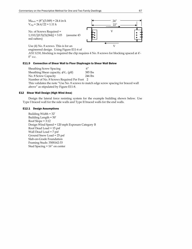
Commentary on the Prescriptive Method for One and Two Family Dwellings 67
MBlock = (8”)(3.049) = 24.4 in-k Vclip = 24.4/22 = 1.11 k No. of Screws Required = 1,110/[(0.5)(3)(244)] = 3.03 (assume 43 mil rafters) Use (4) No. 8 screws. This is for an engineered design. Using Figure E11-6 of AISI S230, blocking is required the clip requires 4 No. 8 screws for blocking spaced at 4’-0” o.c.
E11.9 Connection of Shear Wall to Floor Diaphragm to Shear Wall Below
Sheathing Screw Spacing 6” Sheathing Shear capacity, φVn (plf) 385 lbs No. 8 Screw Capacity 246 lbs Number of No. 8 Screws Required Per Foot 2 This validates the note “Use No. 8 screws to match edge screw spacing for braced wall above” as stipulated by Figure E11-8.
E12 Shear Wall Design (High Wind Area)
Design the lateral force resisting system for the example building shown below. Use Type I braced wall for the side walls and Type II braced walls for the end walls.
E12.1 Design Assumptions
Building Width = 32’ Building Length = 50’ Roof Slope = 3:12 Design Wind Speed = 120 mph Exposure Category B Roof Dead Load = 15 psf Wall Dead Load = 7 psf Ground Snow Load = 25 psf Slab-on-Grade Foundation Framing Studs: 350S162-33 Stud Spacing = 16” on center
24” 22”
V
V
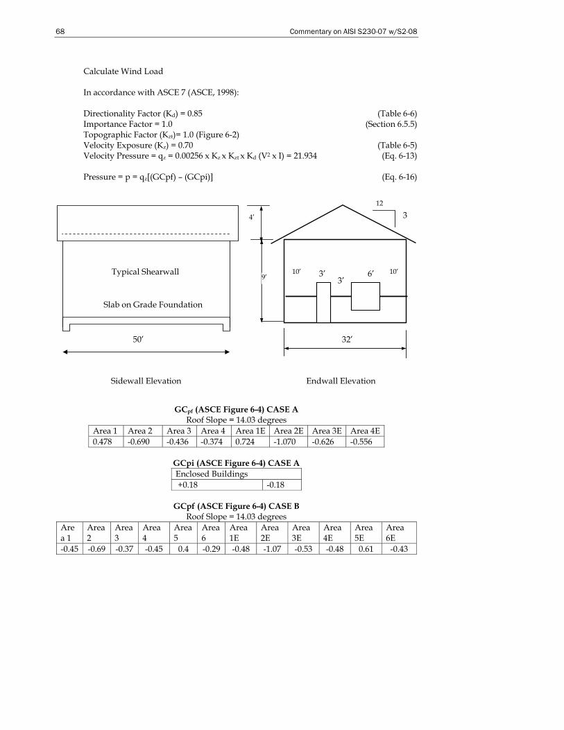
68 Commentary on AISI S230-07 w/S2-08
Calculate Wind Load In accordance with ASCE 7 (ASCE, 1998): Directionality Factor (Kd) = 0.85 (Table 6-6) Importance Factor = 1.0 (Section 6.5.5) Topographic Factor (Kzt)= 1.0 (Figure 6-2) Velocity Exposure (Kz) = 0.70 (Table 6-5) Velocity Pressure = qz = 0.00256 x Kz x Kzt x Kd (V2 x I) = 21.934 (Eq. 6-13) Pressure = p = qz[(GCpf) – (GCpi)] (Eq. 6-16)
GCpf (ASCE Figure 6-4) CASE A
Roof Slope = 14.03 degrees Area 1 Area 2 Area 3 Area 4 Area 1E Area 2E Area 3E Area 4E 0.478 -0.690 -0.436 -0.374 0.724 -1.070 -0.626 -0.556
GCpi (ASCE Figure 6-4) CASE A Enclosed Buildings +0.18 -0.18
GCpf (ASCE Figure 6-4) CASE B
Roof Slope = 14.03 degrees Area 1
Area 2
Area 3
Area 4
Area 5
Area 6
Area 1E
Area 2E
Area 3E
Area 4E
Area 5E
Area 6E
-0.45 -0.69 -0.37 -0.45 0.4 -0.29 -0.48 -1.07 -0.53 -0.48 0.61 -0.43
50’
Sidewall Elevation
Slab on Grade Foundation
Endwall Elevation
12
3
9’
32’
10’ 6’ 10’ 3’ 3’
4’
Typical Shearwall
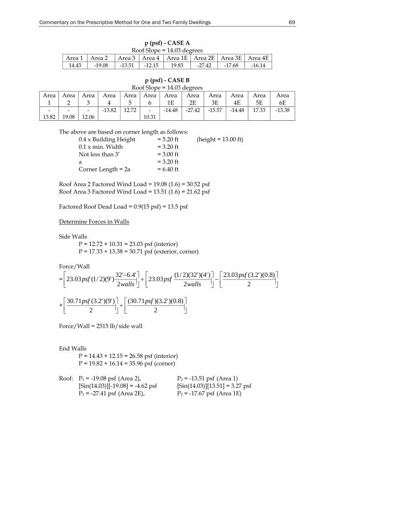
Commentary on the Prescriptive Method for One and Two Family Dwellings 69
p (psf) - CASE A Roof Slope = 14.03 degrees
Area 1 Area 2 Area 3 Area 4 Area 1E Area 2E Area 3E Area 4E 14.43 -19.08 -13.51 -12.15 19.83 -27.42 -17.68 -16.14
p (psf) - CASE B
Roof Slope = 14.03 degrees Area
1 Area
2 Area
3 Area
4 Area
5 Area
6 Area
1E Area
2E Area
3E Area
4E Area
5E Area
6E -
13.82 -
19.08 -
12.06 -13.82 12.72 -
10.31 -14.48 -27.42 -15.57 -14.48 17.33 -13.38
The above are based on corner length as follows: 0.4 x Building Height = 5.20 ft (height = 13.00 ft) 0.1 x min. Width = 3.20 ft Not less than 3’ = 3.00 ft a = 3.20 ft Corner Length = 2a = 6.40 ft Roof Area 2 Factored Wind Load = 19.08 (1.6) = 30.52 psf Roof Area 3 Factored Wind Load = 13.51 (1.6) = 21.62 psf Factored Roof Dead Load = 0.9(15 psf) = 13.5 psf Determine Forces in Walls Side Walls
P = 12.72 + 10.31 = 23.03 psf (interior) P = 17.33 + 13.38 = 30.71 psf (exterior, corner)
Force/Wall
= ⎥⎦⎤
⎢⎣⎡−⎥⎦
⎤⎢⎣⎡+⎥⎦
⎤⎢⎣⎡ −
2)8.0)('2.3(03.23
2)'4)('32)(2/1(03.23
2'4.6'32)'9)(2/1(03.23 psf
wallspsf
wallspsf
+ ⎥⎦⎤
⎢⎣⎡+⎥⎦
⎤⎢⎣⎡
2)8.0)('2.3)(71.30(
2)'9)('2.3(71.30 psfpsf
Force/Wall = 2515 lb/side wall End Walls
P = 14.43 + 12.15 = 26.58 psf (interior) P = 19.82 + 16.14 = 35.96 psf (corner)
Roof: P1 = -19.08 psf (Area 2), P2 = -13.51 psf (Area 1)
[Sin(14.03)][-19.08] = -4.62 psf [Sin(14.03)][13.51] = 3.27 psf P1 = -27.41 psf (Area 2E), P2 = -17.67 psf (Area 1E)
70 Commentary on AISI S230-07 w/S2-08
Total load from roof = 4.62 – 3.27 = 1.35 psf. (typ.) Total load from roof = 2.36 psf (corner)
Force/Wall = (26.58 psf )(9’x1/2)(50’-12.8’)/2 walls + (35.96 psf)(1/2)(9’)(6.4’)
+ (-4.35 psf)(4’)[(50’-12.8’)/2] + (-2.36 psf)(4’)(6.4’) = 3,099 lb/end wall However, in accordance with ASCE 7 the total horizontal shear shall not be less than that determined by neglecting wind roof surfaces. Therefore,
Force/wall = (26.58 psf)(9’/2)(37.2’) + (35.96 psf)(9’/2)(12.8’) = 6,520 lb/2 sides = 3,260 lb
Chords v = 1,258 lb Side wall / 4’ long = 315 plf v = 1,630 lb End wall /5’ long = 326 plf Wall height = 9 feet Maximum chord force = 326(9) = 2,934 lb This force is for an engineered design. Using Table E13-10 a maximum chord strength of 4419 lb is required.
Post: Use (2) 350S162-33 studs braced at 4’ (Pall = 4,945 lb) Hold Downs P = 2,934 lb Attach hold down to each end of each shear wall panel. Use hold-downs with 5/8” diameter bolt (Pall = 3,295 lb). The 3,295 lb hold down capacity is calculated as follows:
Pall = 4,385 lb for 54 mil member with 14 No. 10 screws. Pall = (177 lb/screw)(14)(1.33) = 3,295 lb for 33 mil member.
E12.2 Length of Shear Panel (Side Walls)
P = 2,515/2 panels = 1,258 lb per shear wall In accordance with Table 2211.1(1) of IBC 2000: Vn = 910/2.5 = 364 lb Length of shear panel required = 1,258/364 = 3.46 ft/shear wall
E12.3 Length of Shear Panel (End Walls)
P = 3,260/2 panels = 1,630 lb per shear wall
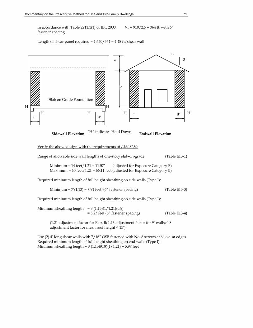
Commentary on the Prescriptive Method for One and Two Family Dwellings 71
In accordance with Table 2211.1(1) of IBC 2000: Vn = 910/2.5 = 364 lb with 6” fastener spacing. Length of shear panel required = 1,630/364 = 4.48 ft/shear wall
Verify the above design with the requirements of AISI S230: Range of allowable side wall lengths of one-story slab-on-grade (Table E13-1)
Minimum = 14 feet/1.21 = 11.57’ (adjusted for Exposure Category B) Maximum = 60 feet/1.21 = 66.11 feet (adjusted for Exposure Category B)
Required minimum length of full height sheathing on side walls (Type I):
Minimum = 7’(1.13) = 7.91 feet (6” fastener spacing) (Table E13-3) Required minimum length of full height sheathing on side walls (Type I): Minimum sheathing length = 8’(1.13)(1/1.21)(0.8)
= 5.23 feet (6” fastener spacing) (Table E13-4)
(1.21 adjustment factor for Exp. B; 1.13 adjustment factor for 9’ walls; 0.8 adjustment factor for mean roof height < 15’)
Use (2) 4’ long shear walls with 7/16” OSB fastened with No. 8 screws at 6” o.c. at edges. Required minimum length of full height sheathing on end walls (Type I): Minimum sheathing length = 8’(1.13)(0.8)(1/1.21) = 5.97 feet
Sidewall Elevation
Slab on Grade Foundation
Endwall Elevation
12
3
9’
5’
4’
5’ 4’ 4’
H H
H H H
H
“H” indicates Hold Down
72 Commentary on AISI S230-07 w/S2-08
(1.21 adjustment factor for Exp. B; 1.13 adjustment factor for 9’ walls; 0.8 adjustment factor for mean roof height < 15’)
Since this is a Type II shear wall, check the applicability of any factors: The length of full height sheathing cannot be multiplied by any factor from Table E12.1 because the roof dead load is greater than 11 psf and the wall dead load is not less than 7 psf. L = 5.97 feet. (6” o.c. edge fastener spacing) Use (2) 5’ long shear walls with 7/16” OSB fastened with No. 8 screws at 6” o.c. at edges.
E12.4 Braced Wall Hold Down Anchorage
Required hold down anchor force from Table E12.2 = 3,535 lbs. (9-foot walls and 6” screw spacing). F = 3,535/1.4 = 2,525 lb (The 1.4 factor is from Table E12-2 of AISI S230)
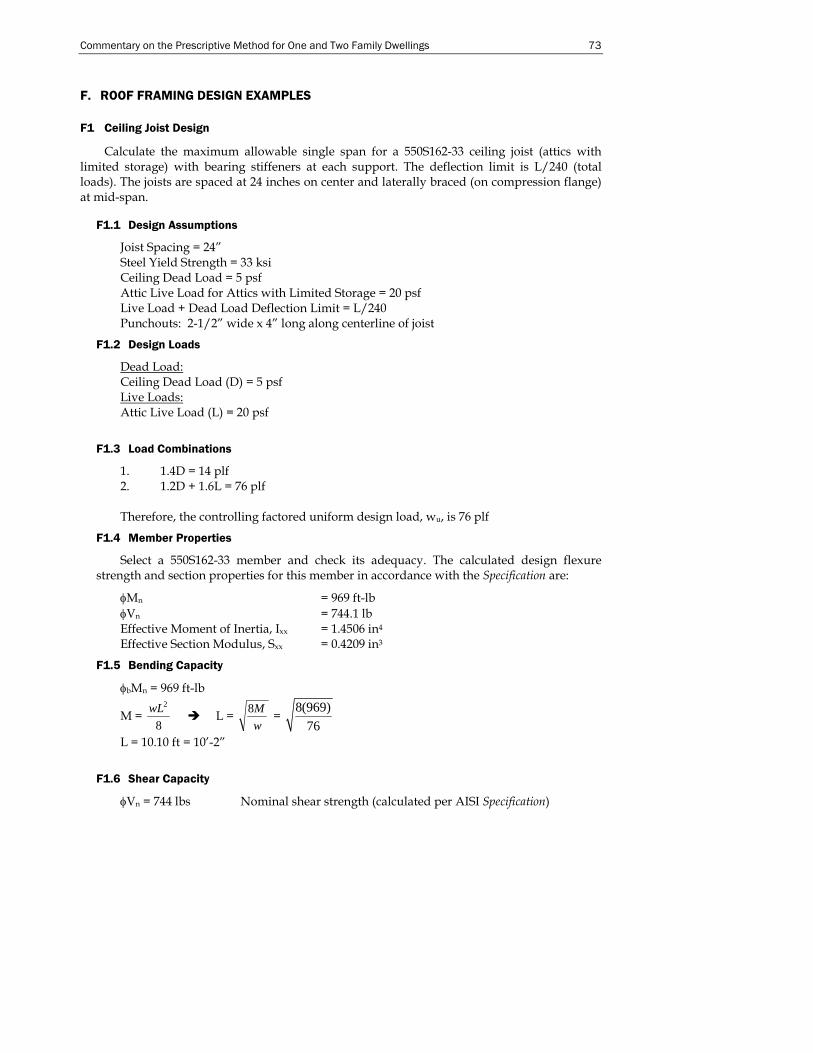
Commentary on the Prescriptive Method for One and Two Family Dwellings 73
F. ROOF FRAMING DESIGN EXAMPLES
F1 Ceiling Joist Design
Calculate the maximum allowable single span for a 550S162-33 ceiling joist (attics with limited storage) with bearing stiffeners at each support. The deflection limit is L/240 (total loads). The joists are spaced at 24 inches on center and laterally braced (on compression flange) at mid-span.
F1.1 Design Assumptions
Joist Spacing = 24” Steel Yield Strength = 33 ksi Ceiling Dead Load = 5 psf Attic Live Load for Attics with Limited Storage = 20 psf Live Load + Dead Load Deflection Limit = L/240 Punchouts: 2-1/2” wide x 4” long along centerline of joist
F1.2 Design Loads
Dead Load: Ceiling Dead Load (D) = 5 psf Live Loads: Attic Live Load (L) = 20 psf
F1.3 Load Combinations
1. 1.4D = 14 plf 2. 1.2D + 1.6L = 76 plf Therefore, the controlling factored uniform design load, wu, is 76 plf
F1.4 Member Properties
Select a 550S162-33 member and check its adequacy. The calculated design flexure strength and section properties for this member in accordance with the Specification are:
φMn = 969 ft-lb φVn = 744.1 lb Effective Moment of Inertia, Ixx = 1.4506 in4 Effective Section Modulus, Sxx = 0.4209 in3
F1.5 Bending Capacity
φbMn = 969 ft-lb
M = 8
2wL L = wM8 =
8(969)76
L = 10.10 ft = 10’-2”
F1.6 Shear Capacity
φVn = 744 lbs Nominal shear strength (calculated per AISI Specification)
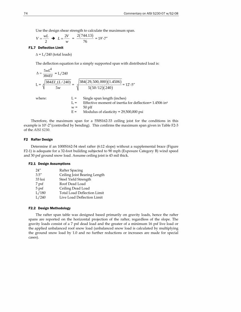
74 Commentary on AISI S230-07 w/S2-08
Use the design shear strength to calculate the maximum span.
2wLV =
wVL 2
= = ( )2 744.13
76 = 19’-7”
F1.7 Deflection Limit
Δ = L/240 (total loads) The deflection equation for a simply supported span with distributed load is:
45384
wLEI
Δ = = L/240
L = 4384 ( / 240)
5xEI Lw
= ( )( )
( )( )3
384 29,500,000 1.45065 50 /12 240
= 12’-5”
where: L = Single span length (inches)
Ix = Effective moment of inertia for deflection= 1.4506 in4 w = 50 plf E = Modulus of elasticity = 29,500,000 psi
Therefore, the maximum span for a 550S162-33 ceiling joist for the conditions in this
example is 10’-2”(controlled by bending). This confirms the maximum span given in Table F2-3 of the AISI S230.
F2 Rafter Design
Determine if an 1000S162-54 steel rafter (6:12 slope) without a supplemental brace (Figure F2-1) is adequate for a 32-foot building subjected to 90 mph (Exposure Category B) wind speed and 30 psf ground snow load. Assume ceiling joist is 43 mil thick.
F2.1 Design Assumptions
24” Rafter Spacing 3.5” Ceiling Joist Bearing Length 33 ksi Steel Yield Strength 7 psf Roof Dead Load 5 psf Ceiling Dead Load L/180 Total Load Deflection Limit L/240 Live Load Deflection Limit
F2.2 Design Methodology
The rafter span table was designed based primarily on gravity loads, hence the rafter spans are reported on the horizontal projection of the rafter, regardless of the slope. The gravity loads consist of a 7 psf dead load and the greater of a minimum 16 psf live load or the applied unbalanced roof snow load (unbalanced snow load is calculated by multiplying the ground snow load by 1.0 and no further reductions or increases are made for special cases).
Commentary on the Prescriptive Method for One and Two Family Dwellings 75
Wind load effects are correlated to equivalent snow loads wind pressures were calculated using the ASCE 7 (ASCE 2005) components and cladding coefficients. Wind loads acting perpendicular to the plane of the rafter were adjusted to represent loads acting orthogonal to the horizontal projection of the rafter (as shown in Figure F2-1. Wind loads were examined for both uplift and downward loads and the worst case was correlated to a corresponding snow load.
F2.3 Design Loads
Dead Load: Roof dead load = (7 psf / cos 26.56°)(2’) = 15.65 psf Live Load: Unbalanced Roof Snow Load (S) = (30 psf)(2’) = 60 plf controls Roof Live Load (Lr) = 16 psf (2’) = 32 plf
Both uplift and inward acting wind loads must be examined and the worst case
converted to an equivalent snow load effect. ASCE 7 (ASCE, 1998) components and cladding pressure coefficients are used to calculate the wind load.
ρ = qh[(GCp) – (GCpi)] lb/ft2 (Eq. 6-18) qh = 0.00256KzKztKdV2I (Eq. 6-13)
Kz = 0.70 for exposure B (Table 6-5) Kzt = 0.72 (maximum value used) (Figure 6-2) Kd = 0.85 (Table 6-6) GCp = -1.4 (Tributary area = 100 ft2) (Figure 6-5B) GCp = +0.3 (Tributary area = 100 ft2) (Figure 6-5B) GCpi = ± 0.18 (Table 6-7)
Downward load (inward): q = 0.00256(0.70)(0.72)(0.85)(90)2[0.3 – (-0.18)] = 4.26 psf Upward load (uplift or outward): q = 0.00256(0.70)(0.72)(0.85)(90)2[-1.4 - (0.18)] = -14 psf
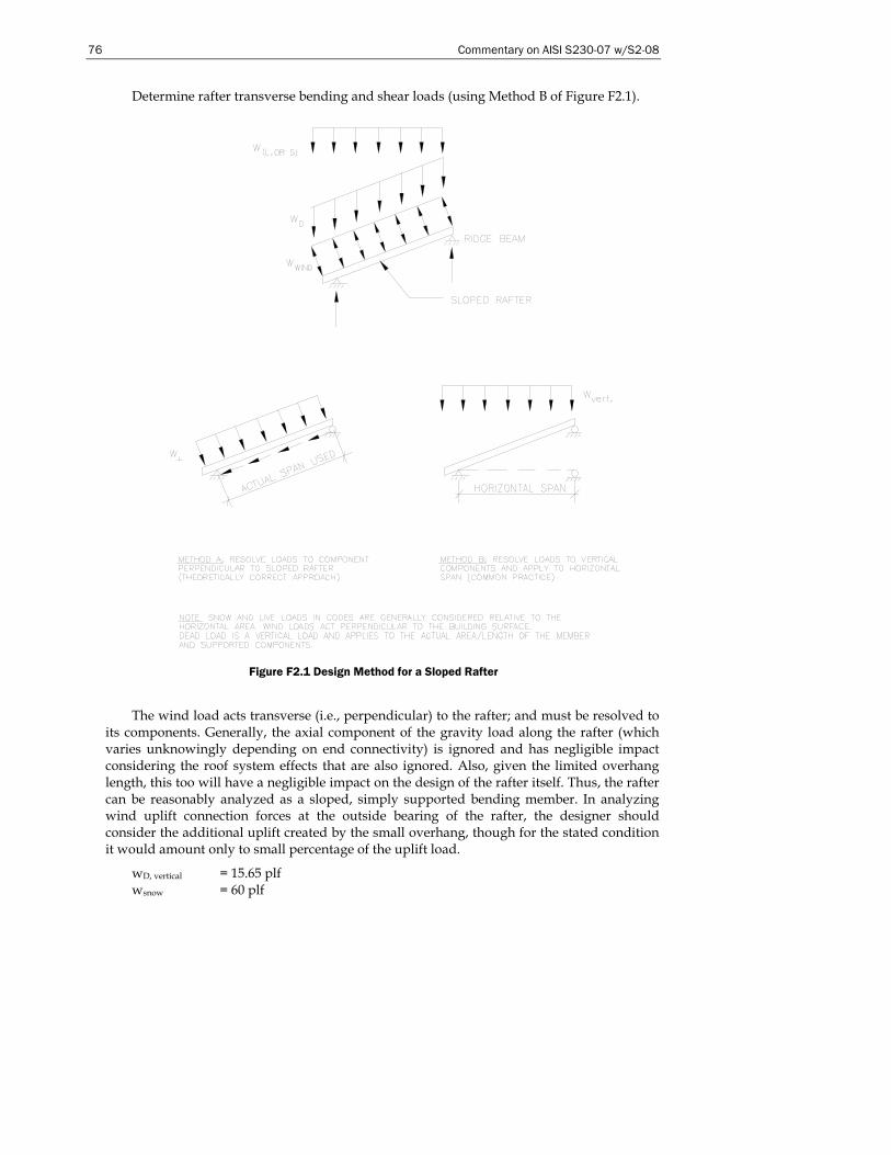
76 Commentary on AISI S230-07 w/S2-08
Determine rafter transverse bending and shear loads (using Method B of Figure F2.1).
Figure F2.1 Design Method for a Sloped Rafter
The wind load acts transverse (i.e., perpendicular) to the rafter; and must be resolved to its components. Generally, the axial component of the gravity load along the rafter (which varies unknowingly depending on end connectivity) is ignored and has negligible impact considering the roof system effects that are also ignored. Also, given the limited overhang length, this too will have a negligible impact on the design of the rafter itself. Thus, the rafter can be reasonably analyzed as a sloped, simply supported bending member. In analyzing wind uplift connection forces at the outside bearing of the rafter, the designer should consider the additional uplift created by the small overhang, though for the stated condition it would amount only to small percentage of the uplift load.
wD, vertical = 15.65 plf wsnow = 60 plf
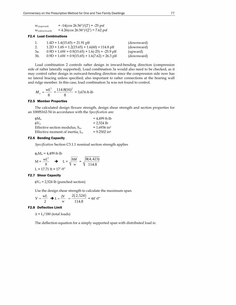
Commentary on the Prescriptive Method for One and Two Family Dwellings 77
wy(upward) = -14(cos 26.56°)2(2’) = -25 psf wy(downward) = 4.26(cos 26.56°)2(2’) = 7.62 psf
F2.4 Load Combinations
1. 1.4D = 1.4(15.65) = 21.91 plf (downward) 2. 1.2D + 1.6S = 1.2(15.65) + 1.6(60) = 114.8 plf (downward) 3a. 0.9D + 1.6W = 0.9(15.65) + 1.6(-25) = -25.9 plf (upward) 3b. 0.9D + 1.6W = 0.9(15.65) + 1.6(7.62) = 26.3 plf (downward) Load combination 2 controls rafter design in inward-bending direction (compression
side of rafter laterally supported). Load combination 3a would also need to be checked, as it may control rafter design in outward-bending direction since the compression side now has no lateral bracing unless specified; also important to rafter connections at the bearing wall and ridge member. In this case, load combination 3a was not found to control.
8
2wLM u = =2114.8(16)
8 = 3,674 ft-lb
F2.5 Member Properties
The calculated design flexure strength, design shear strength and section properties for an 1000S162-54 in accordance with the Specification are:
φMn = 4,499 ft-lb φVn = 2,524 lb Effective section modulus, Sxx = 1.6936 in3 Effective moment of inertia, Ixx = 9.2502 in4
F2.6 Bending Capacity
Specification Section C3.1.1 nominal section strength applies φbMn = 4,499 ft-lb
M = 8
2wL L = wM8 =
8(4, 423)114.8
L = 17.71 ft = 17’-9”
F2.7 Shear Capacity
φVn = 2,524 lb (punched section) Use the design shear strength to calculate the maximum span.
2wLV =
wVL 2
= ( )2 2,524114.8
= = 44’-0”
F2.8 Deflection Limit
Δ = L/180 (total loads) The deflection equation for a simply supported span with distributed load is:
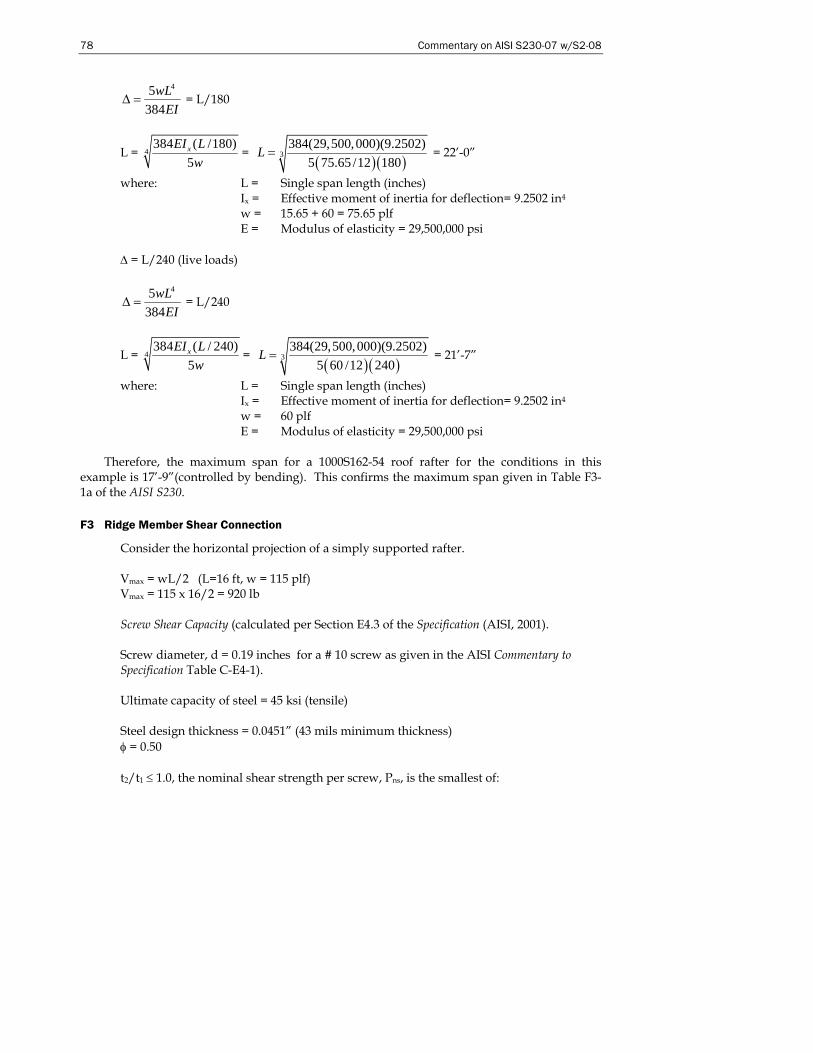
78 Commentary on AISI S230-07 w/S2-08
45384
wLEI
Δ = = L/180
L = 4384 ( /180)
5xEI Lw
= ( )( )
3384(29,500,000)(9.2502)
5 75.65 /12 180L = = 22’-0”
where: L = Single span length (inches) Ix = Effective moment of inertia for deflection= 9.2502 in4 w = 15.65 + 60 = 75.65 plf E = Modulus of elasticity = 29,500,000 psi
Δ = L/240 (live loads)
45384
wLEI
Δ = = L/240
L = 4384 ( / 240)
5xEI Lw
= ( )( )
3384(29,500,000)(9.2502)
5 60 /12 240L = = 21’-7”
where: L = Single span length (inches) Ix = Effective moment of inertia for deflection= 9.2502 in4 w = 60 plf E = Modulus of elasticity = 29,500,000 psi
Therefore, the maximum span for a 1000S162-54 roof rafter for the conditions in this
example is 17’-9”(controlled by bending). This confirms the maximum span given in Table F3-1a of the AISI S230.
F3 Ridge Member Shear Connection
Consider the horizontal projection of a simply supported rafter. Vmax = wL/2 (L=16 ft, w = 115 plf) Vmax = 115 x 16/2 = 920 lb Screw Shear Capacity (calculated per Section E4.3 of the Specification (AISI, 2001). Screw diameter, d = 0.19 inches for a # 10 screw as given in the AISI Commentary to Specification Table C-E4-1). Ultimate capacity of steel = 45 ksi (tensile) Steel design thickness = 0.0451” (43 mils minimum thickness) φ = 0.50 t2/t1 ≤ 1.0, the nominal shear strength per screw, Pns, is the smallest of:

Commentary on the Prescriptive Method for One and Two Family Dwellings 79
Pns = 2322.4 uFdt ⎟
⎠⎞⎜
⎝⎛ (Eq. E4.3.1-1)
Pns = 2.7t1dFu1 (Eq. E4.3.1-2) Pns = 2.7t2dFu2 (Eq. E4.3.1-3) where: t1 = t2 = 0.0451” and Fu1 = Fu2 = 45 ksi Pns = 789 lbs. Screw Pull-Out Capacity (calculated in accordance with Section E4.4 of the AISI Specification (AISI, 2001). Pnot = 0.85(tc)(d)Fu2 (Eq. E4.4.1.1) Pnot = 327 lbs Therefore the design strength for screw shear, φ Pns = 789(0.5) = 394.5 lbs Number of screws required = 920/394.5 = 2.33 screws, Use 3 screws. This confirms the Table F3-3 requirement in AISI S230 of 3 screws.
F4 Ceiling Joist to Rafter Connection
Snow load = 21 psf (30 x 0.7) House width = 32 ft Roof dead load = 7.83 psf Ceiling dead load = 5 psf Spacing = 24 in o.c. No. 10 screw nominal shear capacity = 395 lb (from F3 above)
Figure F4.1 - Roof Loading Diagram
Find the reactions (from Figure F4.1). R = wL/2 R = [(21x1.6+7.83x1.2+5x1.2) x 2] x 32’/2 = 1,536 lb A distributed load of [(21x1.6+7.83x1.2)x2] psf or 86 plf is spread across the length of the building. One fourth of this load will be concentrated at the end walls, joints 1 and 2 (86
21 psf S.L. + 7 psf Roof D.L.
Ceiling D.L. = 5 psf
Rafter Rafter
Ceiling Joist to Rafter
R R
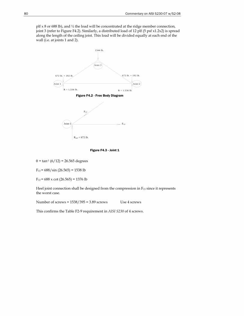
80 Commentary on AISI S230-07 w/S2-08
plf x 8 or 688 lb), and ½ the load will be concentrated at the ridge member connection, joint 3 (refer to Figure F4.2). Similarly, a distributed load of 12 plf (5 psf x1.2x2) is spread along the length of the ceiling joist. This load will be divided equally at each end of the wall (i.e. at joints 1 and 2).
θ = tan-1 (6/12) = 26.565 degrees F13 = 688/sin (26.565) = 1538 lb F12 = 688 x cot (26.565) = 1376 lb Heel joint connection shall be designed from the compression in F13 since it represents the worst case. Number of screws = 1538/395 = 3.89 screws Use 4 screws This confirms the Table F2-9 requirement in AISI S230 of 4 screws.
F13
Rnet = 672 lb.
Joint 1 F12
1344 lb .
R = 1,536 lb .
672 lb . + 192 lb .
Jo int 1
Join t 3
R = 1,536 lb .
Jo int 2
672 lb . + 192 lb .
Figure F4.2 - Free Body Diagram
Figure F4.3 - Joint 1
Commentary on the Prescriptive Method for One and Two Family Dwellings 81
F5 Roof Diaphragm Design (First Example)
Check the adequacy of the roof diaphragm for a 40x60 ft, two-story building with 12:12 roof slope and 8’ wall studs, subjected to 110 mph wind speed, Exposure Category C.
Based on ASCE 7 the following wind pressures were obtained for the given wind speed, exposure and roof slope: Roof pressure = 11.7 psf Roof corner pressure = 14.6 psf Main building pressure = 24.1 psf Main building corner pressure = 30.3 psf Calculate corner area width (2a), where “a” equals 10% of least width or 0.4h (whichever is smaller) but not less than either 4% of least width or 3 feet. a = 10%(40) = 4’ a = 0.4(30) = 12’ a = 3’ Shear = (60’–8’)(8’/2)(24.1 psf)+8’(8’/2)(30.3 psf)+(60’–8’)(20’)(11.7 psf)+20’(8’)(14.6 psf)
= 20,486 lbs.
Roof diaphragm load = 40)2/486,20( = 256 plf
IBC Table 2306.3.1 (ICC, 2000a) provides recommended shear values for wood structural shear panel diaphragms. For 7/16” OSB with 8d-nail spacing, the unblocked shear value is 230 plf (multiplied by wood species reduction factor). The allowable shear values for unblocked diaphragms for 7/16” OSB with No. 8 screws spaced at 6 inches the unblocked shear value is 252 plf (AISI S213-07). Using the AISI S213 diaphragm value, the diaphragm in this example would be adequate.
F6 Roof Diaphragm Design (Second Example)
Check the adequacy of the roof diaphragm in Section F5 for a 30x60 ft two-story building.
Use a = 4’ 2a = 8’
40’
60’
Plan View
Force Direction
60’ Building Length
40’ Building Width
Building
Roof
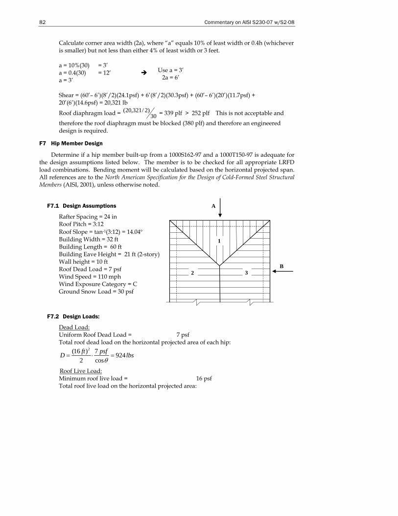
82 Commentary on AISI S230-07 w/S2-08
Calculate corner area width (2a), where “a” equals 10% of least width or 0.4h (whichever is smaller) but not less than either 4% of least width or 3 feet.
a = 10%(30) = 3’ a = 0.4(30) = 12’ a = 3’
Shear = (60’– 6’)(8’/2)(24.1psf) + 6’(8’/2)(30.3psf) + (60’– 6’)(20’)(11.7psf) + 20’(6’)(14.6psf) = 20,321 lb
Roof diaphragm load = 30)2/321,20( = 339 plf > 252 plf This is not acceptable and
therefore the roof diaphragm must be blocked (380 plf) and therefore an engineered design is required.
F7 Hip Member Design
Determine if a hip member built-up from a 1000S162-97 and a 1000T150-97 is adequate for the design assumptions listed below. The member is to be checked for all appropriate LRFD load combinations. Bending moment will be calculated based on the horizontal projected span. All references are to the North American Specification for the Design of Cold-Formed Steel Structural Members (AISI, 2001), unless otherwise noted.
F7.1 Design Assumptions
Rafter Spacing = 24 in Roof Pitch = 3:12 Roof Slope = tan-1(3:12) = 14.04° Building Width = 32 ft Building Length = 60 ft Building Eave Height = 21 ft (2-story) Wall height = 10 ft Roof Dead Load = 7 psf Wind Speed = 110 mph Wind Exposure Category = C Ground Snow Load = 30 psf
F7.2 Design Loads:
Dead Load: Uniform Roof Dead Load = 7 psf Total roof dead load on the horizontal projected area of each hip:
2(16 ) 7 9242 cosft psfD lbs
θ= ⋅ =
Roof Live Load: Minimum roof live load = 16 psf Total roof live load on the horizontal projected area:
Use a = 3’ 2a = 6’
1
2 3
A
B
Commentary on the Prescriptive Method for One and Two Family Dwellings 83
2(16 ) (16 ) 20482rftL psf lbs= =
Roof Snow Load: Roof snow load = 0.7(30 psf) = 21 psf (Governs) Total snow load on the horizontal projected area:
2(16 ) (21 ) 26882ftS psf lbs= =
Wind Loads: Wind loads are calculated in accordance with ASCE 7 Method 2 – Analytical Procedure for MWFRS (ASCE, 2005).
Equation: Comments: ASCE 7 Reference: p i pip qGC q GC= − Rigid Building of All Hts. 6.5.12.2, Eq. 6-17
20.00256i h z zt dq q q K K K V I= = = 6.5.10, Eq. 6-15
Where: Kz = 0.924 Exp. C, Case 1, z = 23 ft Table 6-3 Kzt = 1.0 No Topographic Factor Kd = 0.85 Table 6-4 V = 110 mph 3-Second Gust Wind Speed I = 1.0 Residential Building (Cat I) Table 1-1, Table 6-1
20.00256(0.924)(1.0)(0.85)(110) (1.0) 24.3hq = = lb/ft2
G = 0.85 Rigid Structure Section 6.5.8.1 GCpi = -0.18 or +0.18 Enclosed Buildings Figure 6-5 Wind pressures for wind direction A (h/L = 23/60 = 0.38): Surface 1: Cp = -0.6, -0.09 Figure 6-6 Surface 2: Cp = -0.9, -0.18 Figure 6-6 Surface 3: Cp = -0.9, -0.18 Figure 6-6
1 24.3(0.85)( 0.6) 24.3( 0.18) 16.8 , 8.0p psf psf= − − ± = − − Uplift
or 1 24.3(0.85)( 0.09) 24.3( 0.18) 6.2 , 2.5p psf psf= − − ± = − + Downward
2 3 24.3(0.85)( 0.9) 24.3( 0.18) 23.0 , 14.2p p psf psf= = − − ± = − − Uplift
or 2 3 24.3(0.85)( 0.18) 24.3( 0.18) 8.1 , 0.7p p psf psf= = − − ± = − + Downward
Wind pressures for wind direction B (h/L = 23/32 = 0.72): Surface 1: Cp = -1.08, -0.18 Figure 6-6 Surface 2: Cp = -0.54 Figure 6-6 Surface 3: Cp = -0.83, -0.18 Figure 6-6
84 Commentary on AISI S230-07 w/S2-08
1 24.3(0.85)( 1.08) 24.3( 0.18) 26.7 , 17.9p psf psf= − − ± = − − Uplift
or 1 24.3(0.85)( 0.18) 24.3( 0.18) 8.1 , 0.7p psf psf= − − ± = − + Downward
2 24.3(0.85)( 0.54) 24.3( 0.18) 15.5 , 6.8p psf psf= − − ± = − − Uplift
3 24.3(0.85)( 0.83) 24.3( 0.18) 21.5 , 12.8p psf psf= − − ± = − − Uplift or
3 24.3(0.85)( 0.18) 24.3( 0.18) 8.1 , 0.7p psf psf= − − ± = − + Downward
Wind direction A governs for downward pressure with P1 = +2.5 psf and P2 = P3 = +0.7 psf Vertical component of downward wind load:
1 2.5 cos 2.4P psf psfθ= × =
2 3 0.7 cos 0.7P P psf psfθ= = × = Total downward wind load on the horizontal projected area:
[ ]2(16 ) 2.4 (0.7 ) 205
4 cosdownftW psf psf lbs
θ= + =
×
Wind direction B governs for uplift with P1 = -26.7 psf and P3 = -21.5 psf Vertical component of uplift wind load:
1 26.7 cos 25.9P psf psfθ= − × = −
3 21.5 cos 20.9P psf psfθ= − × = − Total uplift wind load on the horizontal projected area:
[ ]216 25.9 ( 20.9 ) 3087
4 cosupliftW psf psf lbsθ
= − + − = −×
F7.3 Load Combinations
The load combinations listed below will be checked:
1. 1.2D +1.6(Lr or S) +0.8Wdown 2. 1.2D + 1.6Wdown + 0.5(Lr or S) 3. 0.9D + 1.6Wuplift Uplift check
Controlling design loads:
Max. Downward (load case 1), Wu = 1.2(924 lbs) + 1.6(2688 lbs) + 0.8(205 lbs) = 5573 lbs
Max. Uplift (load case 3), Wu = 0.9(924 lbs) + 1.6(-3087 lbs) = -4107 lbs
F7.4 Material and Section Properties
The calculated design flexure strength, design shear strength and section properties for a 1000S162-97 and a 1000T150-97 in accordance with the Specification are:
Fy (track and C-section) = 50 ksi Sx = 6.4479 in3 Ix = 33.387 in4
Commentary on the Prescriptive Method for One and Two Family Dwellings 85
φMn = 271.39 k-in φVn = 9.542 k
F7.5 Bending Check
Maximum downward load governs for bending. Unsupported length of the compression flange for both positive and negative moment is the same. The jack rafters connected to the hip member resists lateral torsional buckling for both gravity loads and uplift.
Total triangular load supported by the hip member: Wu = 5573 lbs Applied bending moment:
120.128 0.128(5573 )(16 ) 2 1941000u uM W L lbs ft k in⎛ ⎞= = = −⎜ ⎟
⎝ ⎠
194 271u nM k in M k inφ= − ≤ = − ok Therefore, the hip member composed of 1000S167-97 and 1000T1500-97 is adequate for bending.
F7.6 Shear Check
Maximum downward load governs for bending. Unsupported length of the compression flange for both positive and negative moment is the same. The jack rafters connected to the hip member resists lateral torsional buckling for both gravity loads and uplift.
Total triangular load supported by the hip member: Wu = 5573 lbs Applied shear:
2 2 (5573 ) 37153 3u uV W lbs lbs= = =
3715 3.715 9.541000u n
lbsV k V kφ= = ≤ = ok
Therefore, the hip member composed of 1000S167-97 and 1000T1500-97 is adequate for shear.
F7.7 Deflection Check
Total load deflection limit is L/180 and is based on service dead load plus roof snow. Total service load supported by the hip member: W = 924 lbs + 2688 lbs = 3612 lbs
22.63 12 1.51180 180allowL ft in×
Δ = = =
3 3
4
0.01304 0.01304(3612 )(22.63 ) (1728) 0.9629,500,000 (33.387 )tot
x
WL lbs ft inEI psi in
Δ = = =
Δtot = 0.96 inches < Δallow = 1.51 inches ok
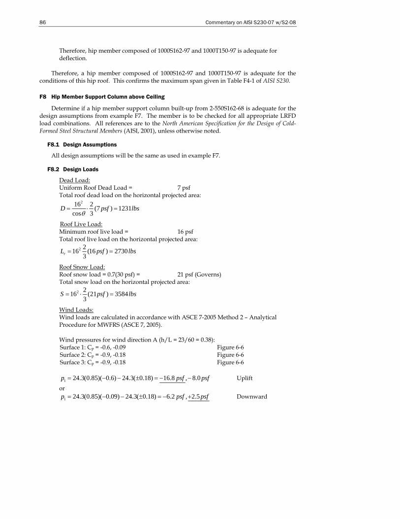
86 Commentary on AISI S230-07 w/S2-08
Therefore, hip member composed of 1000S162-97 and 1000T150-97 is adequate for deflection.
Therefore, a hip member composed of 1000S162-97 and 1000T150-97 is adequate for the conditions of this hip roof. This confirms the maximum span given in Table F4-1 of AISI S230.
F8 Hip Member Support Column above Ceiling
Determine if a hip member support column built-up from 2-550S162-68 is adequate for the design assumptions from example F7. The member is to be checked for all appropriate LRFD load combinations. All references are to the North American Specification for the Design of Cold-Formed Steel Structural Members (AISI, 2001), unless otherwise noted.
F8.1 Design Assumptions
All design assumptions will be the same as used in example F7.
F8.2 Design Loads
Dead Load: Uniform Roof Dead Load = 7 psf Total roof dead load on the horizontal projected area:
216 2 (7 ) 1231cos 3
D psf lbsθ
= ⋅ =
Roof Live Load: Minimum roof live load = 16 psf Total roof live load on the horizontal projected area:
2 216 (16 ) 27303rL psf lbs= =
Roof Snow Load: Roof snow load = 0.7(30 psf) = 21 psf (Governs) Total snow load on the horizontal projected area:
2 216 (21 ) 35843
S psf lbs= ⋅ =
Wind Loads: Wind loads are calculated in accordance with ASCE 7-2005 Method 2 – Analytical Procedure for MWFRS (ASCE 7, 2005). Wind pressures for wind direction A (h/L = 23/60 = 0.38): Surface 1: Cp = -0.6, -0.09 Figure 6-6 Surface 2: Cp = -0.9, -0.18 Figure 6-6 Surface 3: Cp = -0.9, -0.18 Figure 6-6
1 24.3(0.85)( 0.6) 24.3( 0.18) 16.8 , 8.0p psf psf= − − ± = − − Uplift
or 1 24.3(0.85)( 0.09) 24.3( 0.18) 6.2 , 2.5p psf psf= − − ± = − + Downward
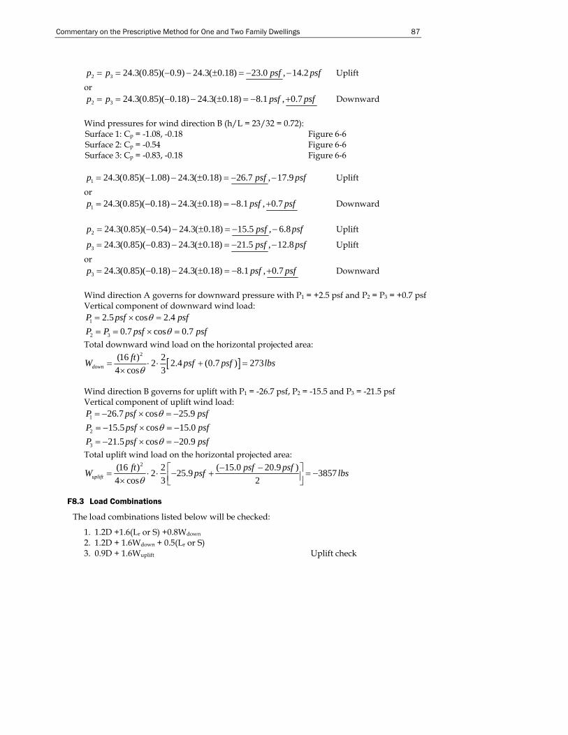
Commentary on the Prescriptive Method for One and Two Family Dwellings 87
2 3 24.3(0.85)( 0.9) 24.3( 0.18) 23.0 , 14.2p p psf psf= = − − ± = − − Uplift
or 2 3 24.3(0.85)( 0.18) 24.3( 0.18) 8.1 , 0.7p p psf psf= = − − ± = − + Downward
Wind pressures for wind direction B (h/L = 23/32 = 0.72): Surface 1: Cp = -1.08, -0.18 Figure 6-6 Surface 2: Cp = -0.54 Figure 6-6 Surface 3: Cp = -0.83, -0.18 Figure 6-6
1 24.3(0.85)( 1.08) 24.3( 0.18) 26.7 , 17.9p psf psf= − − ± = − − Uplift or
1 24.3(0.85)( 0.18) 24.3( 0.18) 8.1 , 0.7p psf psf= − − ± = − + Downward
2 24.3(0.85)( 0.54) 24.3( 0.18) 15.5 , 6.8p psf psf= − − ± = − − Uplift
3 24.3(0.85)( 0.83) 24.3( 0.18) 21.5 , 12.8p psf psf= − − ± = − − Uplift
or 3 24.3(0.85)( 0.18) 24.3( 0.18) 8.1 , 0.7p psf psf= − − ± = − + Downward
Wind direction A governs for downward pressure with P1 = +2.5 psf and P2 = P3 = +0.7 psf Vertical component of downward wind load:
1 2.5 cos 2.4P psf psfθ= × =
2 3 0.7 cos 0.7P P psf psfθ= = × = Total downward wind load on the horizontal projected area:
[ ]2(16 ) 22 2.4 (0.7 ) 273
4 cos 3downftW psf psf lbs
θ= ⋅ ⋅ + =
×
Wind direction B governs for uplift with P1 = -26.7 psf, P2 = -15.5 and P3 = -21.5 psf Vertical component of uplift wind load:
1 26.7 cos 25.9P psf psfθ= − × = −
2 15.5 cos 15.0P psf psfθ= − × = −
3 21.5 cos 20.9P psf psfθ= − × = − Total uplift wind load on the horizontal projected area:
2(16 ) 2 ( 15.0 20.9 )2 25.9 38574 cos 3 2uplift
ft psf psfW psf lbsθ
− −⎡ ⎤= ⋅ ⋅ − + = −⎢ ⎥× ⎣ ⎦
F8.3 Load Combinations
The load combinations listed below will be checked:
1. 1.2D +1.6(Lr or S) +0.8Wdown 2. 1.2D + 1.6Wdown + 0.5(Lr or S) 3. 0.9D + 1.6Wuplift Uplift check
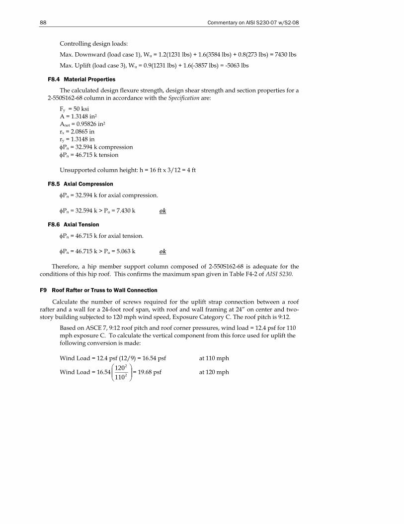
88 Commentary on AISI S230-07 w/S2-08
Controlling design loads:
Max. Downward (load case 1), Wu = 1.2(1231 lbs) + 1.6(3584 lbs) + 0.8(273 lbs) = 7430 lbs
Max. Uplift (load case 3), Wu = 0.9(1231 lbs) + 1.6(-3857 lbs) = -5063 lbs
F8.4 Material Properties
The calculated design flexure strength, design shear strength and section properties for a 2-550S162-68 column in accordance with the Specification are:
Fy = 50 ksi A = 1.3148 in2 Anet = 0.95826 in2 rx = 2.0865 in ry = 1.3148 in φPn = 32.594 k compression φPn = 46.715 k tension Unsupported column height: h = 16 ft x 3/12 = 4 ft
F8.5 Axial Compression
φPn = 32.594 k for axial compression. φPn = 32.594 k > Pu = 7.430 k ok
F8.6 Axial Tension
φPn = 46.715 k for axial tension. φPn = 46.715 k > Pu = 5.063 k ok
Therefore, a hip member support column composed of 2-550S162-68 is adequate for the conditions of this hip roof. This confirms the maximum span given in Table F4-2 of AISI S230.
F9 Roof Rafter or Truss to Wall Connection
Calculate the number of screws required for the uplift strap connection between a roof rafter and a wall for a 24-foot roof span, with roof and wall framing at 24” on center and two-story building subjected to 120 mph wind speed, Exposure Category C. The roof pitch is 9:12.
Based on ASCE 7, 9:12 roof pitch and roof corner pressures, wind load = 12.4 psf for 110 mph exposure C. To calculate the vertical component from this force used for uplift the following conversion is made: Wind Load = 12.4 psf (12/9) = 16.54 psf at 110 mph
Wind Load = 16.54 ⎟⎟⎠
⎞⎜⎜⎝
⎛2
2
110120 = 19.68 psf at 120 mph
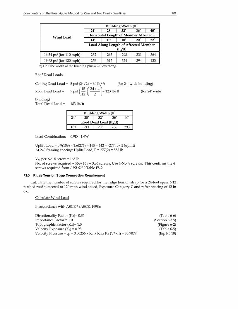
Commentary on the Prescriptive Method for One and Two Family Dwellings 89
Building Width (ft) 24’ 28’ 32’ 36’ 40’
Horizontal Length of Member Affected(1)
14’ 16’ 18’ 20’ 22’ Wind Load
Load Along Length of Affected Member (lb/ft)
16.54 psf (for 110 mph) -232 -265 -298 -331 -364 19.68 psf (for 120 mph) -276 -315 -354 -394 -433
(1) Half the width of the building plus a 2-ft overhang Roof Dead Loads: Ceiling Dead Load = 5 psf (24/2) = 60 lb/ft (for 24’ wide building)
Roof Dead Load = 7 psf 15 24 412 2
+⎛ ⎞⎛ ⎞⎜ ⎟⎜ ⎟⎝ ⎠⎝ ⎠
= 123 lb/ft (for 24’ wide
building) Total Dead Load = 183 lb/ft
Building Width (ft) 24’ 28’ 32’ 36’ 40’
Roof Dead Load (lb/ft) 183 211 238 266 293
Load Combination: 0.9D - 1.6W Uplift Load = 0.9(183) – 1.6(276) = 165 – 442 = -277 lb/ft (uplift) At 24” framing spacing: Uplift Load, P = 277(2) = 553 lb Vall per No. 8 screw = 165 lb No. of screws required = 553/165 = 3.36 screws, Use 4-No. 8 screws. This confirms the 4 screws required from AISI S230 Table F8-2
F10 Ridge Tension Strap Connection Requirement
Calculate the number of screws required for the ridge tension strap for a 24-foot span, 6:12 pitched roof subjected to 120 mph wind speed, Exposure Category C and rafter spacing of 12 in o.c.
Calculate Wind Load In accordance with ASCE 7 (ASCE, 1998): Directionality Factor (Kd)= 0.85 (Table 6-6) Importance Factor = 1.0 (Section 6.5.5) Topographic Factor (Kzt)= 1.0 (Figure 6-2) Velocity Exposure (Kz) = 0.98 (Table 6-5) Velocity Pressure = qz = 0.00256 x Kz x Kzt x Kd (V2 x I) = 30.7077 (Eq. 6.5.10)
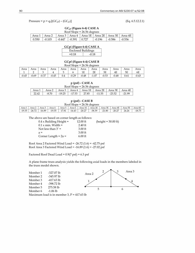
90 Commentary on AISI S230-07 w/S2-08
Pressure = p = qz[(GCpf) – (GCpi)] (Eq. 6.5.12.2.1)
GCpf (Figure 6-4) CASE A Roof Slope = 26.56 degrees
Area 1 Area 2 Area 3 Area 4 Area 1E Area 2E Area 3E Area 4E 0.550 -0.103 -0.447 -0.391 0.727 -0.196 -0.586 -0.536
GCpi (Figure 6-4) CASE A
Enclosed Buildings +0.18 -0.18
GCpf (Figure 6-4) CASE B Roof Slope = 26.56 degrees
Area 1
Area 2
Area 3
Area 4
Area 5
Area 6
Area 1E
Area 2E
Area 3E
Area 4E
Area 5E
Area 6E
-0.45 -0.69 -0.37 -0.45 0.4 -0.29 -0.48 -1.07 -0.53 -0.48 0.61 -0.43
p (psf) - CASE A Roof Slope = 26.56 degrees
Area 1 Area 2 Area 3 Area 4 Area 1E Area 2E Area 3E Area 4E 22.42 -8.70 -19.25 -17.53 27.85 -11.55 -23.52 -21.99
p (psf) - CASE B
Roof Slope = 26.56 degrees Area 1 Area 2 Area 3 Area 4 Area 5 Area 6 Area 1E Area 2E Area 3E Area 4E Area 5E Area 6E -19.35 -26.72 -16.89 -19.35 17.81 -14.43 -20.27 -38.39 -21.80 -20.27 24.26 -18.73
The above are based on corner length as follows: 0.4 x Building Height = 12.00 ft (height = 30.00 ft) 0.1 x min. Width = 2.40 ft Not less than 3’ = 3.00 ft a = 3.00 ft Corner Length = 2a = 6.00 ft Roof Area 2 Factored Wind Load = -26.72 (1.6) = -42.75 psf Roof Area 3 Factored Wind Load = -16.89 (1.6) = -27.02 psf Factored Roof Dead Load = 0.9(7 psf) = 6.3 psf A plane frame truss analysis yields the following axial loads in the members labeled in the truss model shown. Member 1 -327.07 lb Member 2 -345.97 lb Member 3 -417.63 lb Member 4 -398.72 lb Member 5 275.58 lb Member 6 -1.06 lb Maximum load is in member 3, P = 417.63 lb
Area 2 Area 3
1
6 5
3
4
2
Commentary on the Prescriptive Method for One and Two Family Dwellings 91
Vall per No. 8 screw = 165 lb No. of screws required = 417.63 = 2.54 screws, Use 3-No. 8 screws at each end of strap. This confirms the 3 screws required from AISI S230 Table F8-3.
F11 Ridge Tension Strap Design
Calculate the minimum thickness of 1.25” steel strap with 3-No. 8 screws. T = A (0.6Fy) T = 3(165) = 495 lb 495 = [1.25(t)][33,000(0.6)(1.33)] t = 0.015 in Use 33-mil strap. This confirms a 33-mil strap required from AISI S230 Table F8-5.
92 Commentary on AISI S230-07 w/S2-08
REFERENCES
(AFPA, 2001), Wood Frame Construction Manual, American Forest and Paper Association, Washington DC, 2001.
(AISC, 1991), Structural Performance Requirements For Domestic Steel Framing, Australian Institute of Steel Construction, Milsons Point, Australia, 1991.
(AISI, 1996), Specification for the Design of Cold-Formed Steel Structural Members, 1996 Edition with 1999 Supplement, American Iron and Steel Institute, Washington, DC, 1999.
(AISI, 2001), North American Specification for the Design of Cold-Formed Steel Structural Members, 2001 Edition with 2004 Supplement, American Iron and Steel Institute, Washington, DC, 2004.
(AISI S200-07), North American Standard for Cold-Formed Steel Framing – General Provisions, American Iron and Steel Institute, Washington, DC, 2007.
(AISI S201-07), North American Standard for Cold-Formed Steel Framing – Product Data, American Iron and Steel Institute, Washington, DC, 2007.
(AISI S210-07), North American Standard for Cold-Formed Steel Framing – Roof and Floor System Design, American Iron and Steel Institute, Washington, DC, 2007.
(AISI S211-07), North American Standard for Cold-Formed Steel Framing – Wall Stud Design, American Iron and Steel Institute, Washington, DC, 2007.
(AISI S212-07), North American Standard for Cold-Formed Steel Framing – Header Design, American Iron and Steel Institute, Washington, DC, 2007.
(AISI S213-07), North American Standard for Cold-Formed Steel Framing – Lateral Design, American Iron and Steel Institute, Washington, DC, 2007.
(AISI S214-07), North American Standard for Cold-Formed Steel Framing – Truss Design, American Iron and Steel Institute, Washington, DC, 2007.
(AISI S230-07), North American Standard for Cold-Formed Steel Framing – Prescriptive Method for One and Two Family Dwellings, American Iron and Steel Institute, Washington, DC, 2007.
(ASCE, 1998), ASCE 7, Minimum Design Loads for Buildings and Other Structures, American Society of Civil Engineers, Reston VA, 1998.
(ASCE, 2005), ASCE 7, Minimum Design Loads for Buildings and Other Structures, American Society of Civil Engineers, Reston VA, 2005.
(ASTM, 2007), ASTM C954, Standard Specification for Steel Drill Screws for the Application of Gypsum Panel Products or Metal Plaster Bases to Steel Studs From 0.033 in. (0.84 mm) to 0.112 in. (2.84 mm) in Thickness, ASTM International, West Conshohocken PA, 2000.
(ASTM, 2007), ASTM C1002, Standard Specification for Steel Self-Piercing Tapping Screws for the Application of Gypsum Panel Products or Metal Plaster Bases to Wood Studs or Steel Studs, ASTM International, West Conshohocken PA, 2001.
(ICC, 2006a), International Building Code, International Code Council Falls Church, VA, 2006.
(ICC, 2006b), International Residential Code, International Code Council Falls Church, VA, 2006.
Downey, B.W, Stephens, S.F., and LaBoube, R.A., (2005) “Cold-Formed Steel Gable End Wall Design for the Prescriptive Method for One and Two Family Dwellings,” Final Report, Department of Civil Engineering, Wei-Wen Yu Center for Cold-Formed Steel Structures, University of Missouri-Rolla, Rolla, MO.
Commentary on the Prescriptive Method for One and Two Family Dwellings 93
(NAHBRC, 2003), Hybrid Wood and Steel Sole Plate Connection Walls to Floors Testing Report, National Association of Home Builders’ Research Center, Upper Marlboro, MD, 2003.
Sivakumaran, K.S. (2007), Reinforcement Schemes for Cold-Formed Steel Joists Having Web Openings, Final Report, McMaster Univesity, Hamilton, Ontario, Canada, 2007.
Vagh, Dolan and Easterling (2000), Effect of Anchorage and Sheathing Configuration on the Cyclic Response of Long Steel-Frame Shear Walls, Report No. TE-2000-002, Virginia Polytechnic Institute and State University, Blacksburg, VA, 2000.
Waldo, L., Stephens, S.F., and LaBoube, R.A., (2006), “Residential Hip Roof Framing Using Cold-Formed Steel Members,” Final Report, Department of Civil Engineering, Wei-Wen Yu Center for Cold-Formed Steel Structures, University of Missouri-Rolla, Rolla, MO.
Wiss, Janney, Elstner Associates (1977), Report Number 73345, Report of Laboratory Tests and Analytical Studies of Structural Characteristics of Cold-Formed Steel-Joists Floor Systems, San Francisco, CA, 1977.
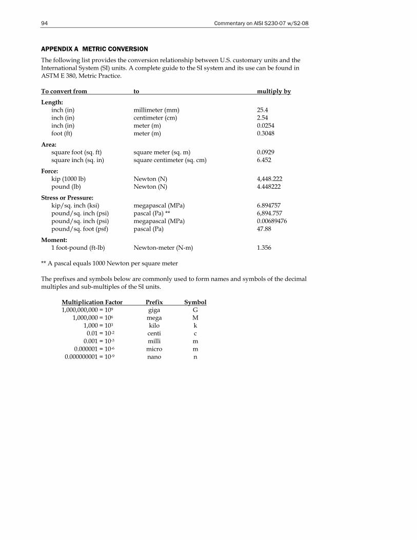
94 Commentary on AISI S230-07 w/S2-08
APPENDIX A METRIC CONVERSION
The following list provides the conversion relationship between U.S. customary units and the International System (SI) units. A complete guide to the SI system and its use can be found in ASTM E 380, Metric Practice. To convert from to multiply by
Length: inch (in) millimeter (mm) 25.4 inch (in) centimeter (cm) 2.54 inch (in) meter (m) 0.0254 foot (ft) meter (m) 0.3048
Area: square foot (sq. ft) square meter (sq. m) 0.0929 square inch (sq. in) square centimeter (sq. cm) 6.452
Force: kip (1000 lb) Newton (N) 4,448.222 pound (lb) Newton (N) 4.448222
Stress or Pressure: kip/sq. inch (ksi) megapascal (MPa) 6.894757 pound/sq. inch (psi) pascal (Pa) ** 6,894.757 pound/sq. inch (psi) megapascal (MPa) 0.00689476 pound/sq. foot (psf) pascal (Pa) 47.88
Moment: 1 foot-pound (ft-lb) Newton-meter (N-m) 1.356
** A pascal equals 1000 Newton per square meter The prefixes and symbols below are commonly used to form names and symbols of the decimal multiples and sub-multiples of the SI units.
Multiplication Factor Prefix Symbol 1,000,000,000 = 109 giga G 1,000,000 = 106 mega M 1,000 = 103 kilo k 0.01 = 10-2 centi c 0.001 = 10-3 milli m 0.000001 = 10-6 micro m 0.000000001 = 10-9 nano n

1 1 4 0 C o n n e c t i c u t A v e n u e N W S u i t e 7 0 5 W a s h i n g t o n , D C 2 0 0 3 6 w w w . s t e e l . o r g
AISI S230-07 w/2-08-C
N a t i o n a l H o u s i n g C e n t e r 1 2 0 1 1 5 t h S t r e e t N W S u i t e 3 2 0 W a s h i n g t o n , D C 2 0 0 0 5 w w w . s t e e l f r a m i n g a l l i a n c e . c o m


![CD/CDX - EBARA7 CD_CDX 50Hz MATERIALS TABLE Ref. Name Material 1 Casing AISI 304 / AISI 316 [5] 24 Priming plug AISI 303 / AISI 316 [5] 3 Motor bracket Aluminium 25 Drain plug AISI](https://img.pdfslide.us/doc/110x75/6103836052038a666e315b88/cdcdx-7-cdcdx-50hz-materials-table-ref-name-material-1-casing-aisi-304-aisi.jpg)