Embed Size (px)
Citation preview

AISC Steel & Timber Research for High-Rise Residential Buildings Final Report December 4th, 2017
SOM Designed Benchmark Concrete Building © Skidmore, Owings, and Merrill, LLP 2017 224s Michigan Avenue Suite 1000 Chicago, IL 60604

Table of Contents
SECTION 1: INTRODUCTION ..................................................................................................................................... 4
1.1 GOALS ............................................................................................................................................................................... 4 1.2 RESEARCH APPROACH ..................................................................................................................................................... 4 1.3 STRUCTURAL SYSTEM DESCRIPTION ............................................................................................................................... 6
SECTION 2: SYSTEM REQUIREMENTS .................................................................................................................. 11
2.1 CRITICAL ISSUES ............................................................................................................................................................. 11 2.2 DESIGN PROCESS ........................................................................................................................................................... 13
SECTION 3: NON-STRUCTURAL CONSIDERATIONS .......................................................................................... 17
3.1 CODE ANALYSIS .............................................................................................................................................................. 17 3.2 FIRE DESIGN ................................................................................................................................................................... 18 3.3 ACOUSTICS ...................................................................................................................................................................... 18 3.4 MOISTURE PROTECTION ................................................................................................................................................. 18 3.5 EXTERIOR WALL .............................................................................................................................................................. 19 3.6 OTHER NON-STRUCTURAL SYSTEMS ............................................................................................................................. 20
SECTION 4: BENCHMARK COMPARISON ............................................................................................................. 21
4.1 MATERIAL TAKE-OFFS .................................................................................................................................................... 21 4.2 COST AND SCHEDULE CONSIDERATIONS ....................................................................................................................... 23
SECTION 5: VERIFICATION REQUIREMENTS ....................................................................................................... 25
5.1 TESTING .......................................................................................................................................................................... 25
SECTION 6: CONCLUSIONS .................................................................................................................................... 26
AISC Steel & Timber Research for pg. 2 © 2017 Skidmore, Owings & Merrill, LLP
High-Rise Residential Buildings Final Report – December 4th 2017
Acknowledgments
This research study has been funded by the American Institute of Steel Construction. The AISC’s research programs are well known and highly respected for advancing the state of the art of steel design and construction. The AISC’s research activities help to improve steel codes and specifications, reduce the cost of steel construction, and improve the performance of steel buildings and bridges. For more information on this report or to contact the AISC, please visit the research website:
https://www.aisc.org/technical-resources/research/
AISC Steel & Timber Research for pg. 3 © 2017 Skidmore, Owings & Merrill, LLP
High-Rise Residential Buildings Final Report – December 4th 2017
Section 1: Introduction
1.1 Goals
The goal of the research project was to determine the viability of the proposed structural system in the high-rise residential building market. The proposed structural system combines steel framing and a composite mass-timber floor system which maximizes the advantages of each material. Structural steel framing is provided for its superior spanning capabilities and the composite mass-timber floor system is provided for its lightweight properties. The resulting combination is able to achieve column bay sizes consistent with flat plate concrete construction and a flat soffit condition. These benefits would not be economically feasible with an all mass-timber system which would either require deep beams for the bay sizes or a tighter column spacing for a flat soffit condition. The proposed system is able to achieve both benefits while maintaining the prefabricated and lightweight benefits of each material.
The research project has been documented in this report and a supplementary set of 11x17 sketches. The sketches include system renderings, floor framing plans, and structural details of the proposed system. These sketches are also included in the report where relevant to the topic discussed. The provided details have been refined based on review and comment from steel fabricators and timber manufacturers. Preliminary pricing for the steel and timber components were prepared by the reviewers to help determine if the system would be viable in the high-rise residential market. The preliminary pricing is available from the AISC upon request. The intent of these documents, along with the pricing information, is to identify the advantages and challenges of the system and the next steps which will be necessary to bring the system to market.
1.2 Research Approach
The approach for determining the market viability of the system was to compare the system to a benchmark building which utilizes a conventional concrete structure. This approach gives context for the structural details selected and shows that the proposed system could be marketable in terms of bay sizes. The benchmark building selected is a 9-story tall residential building which was recently completed in California and was designed by SOM. This building was selected because it is an efficient concrete structure which is representative of the high-rise residential market. Representative structural and architectural plans of the benchmark building are provided on the following page, refer to Figures 1.1 and 1.2. The proposed steel and timber structural system is compared against the benchmark building in Section 4 of this report.
AISC Steel & Timber Research for pg. 4 © 2017 Skidmore, Owings & Merrill, LLP
High-Rise Residential Buildings Final Report – December 4th 2017

Figure 1.1: Benchmark Concrete Building Framing Plan
Figure 1.2: Benchmark Concrete Building Architectural Plan
AISC Steel & Timber Research for pg. 5 © 2017 Skidmore, Owings & Merrill, LLP
High-Rise Residential Buildings Final Report – December 4th 2017

1.3 Structural System Description
The system consists of structural steel framing and composite cross-laminated timber (CLT) floor planks. The CLT planks are topped with a 2½” thick concrete topping slab which is required for durability, acoustics, and fire resistance of the floor framing system. Composite action between the topping slab and the mass-timber floor planks is achieved using structural screws designed to provide composite behavior, although other types of shear connectors could be considered. The topping slab is reinforced to make the composite floor system continuous over steel beam supports. The structural system is illustrated with Figures 1.3 and 1.4 on the following page.
The steel beams have been designed to be asymmetrical in order to simplify the placement of the timber decks on the bottom flanges. The mass-timber floor planks will be notched at the bearing location to create a flat soffit condition with the bottom flange of the steel beams. This notching process is expected to be part of the ordinary CNC fabrication process of the CLT panels. The beams are designed as composite with the concrete topping slab. Composite action is assumed to be achieved by concrete bonding to the steel beam and will require testing to confirm this behavior. Alternatively, shear connectors could be provided to avoid testing but would require revisiting the proposed details to accommodate the space for the shear connectors. The steel beams are designed with end-plate moment connections for stiffness to achieve the 27’-6” span with a depth profile within the thickness of the composite-timber deck. The plan layout of members and corresponding details are provided in Figures 1.5 to 1.8.
The remainder of the structure is intended to use standard structural steel building details. The gravity columns consist of structural steel wide flange shapes. The lateral load resisting system consists of braced frames at the stair and elevator cores of the building. Other lateral load resisting systems could also be used with this system but are not the focus of this study.
The CLT floor planks are assumed to be placed by the steel erector. This approach may not be possible in all markets and should be confirmed by the General Contractor.
AISC Steel & Timber Research for pg. 6 © 2017 Skidmore, Owings & Merrill, LLP
High-Rise Residential Buildings Final Report – December 4th 2017
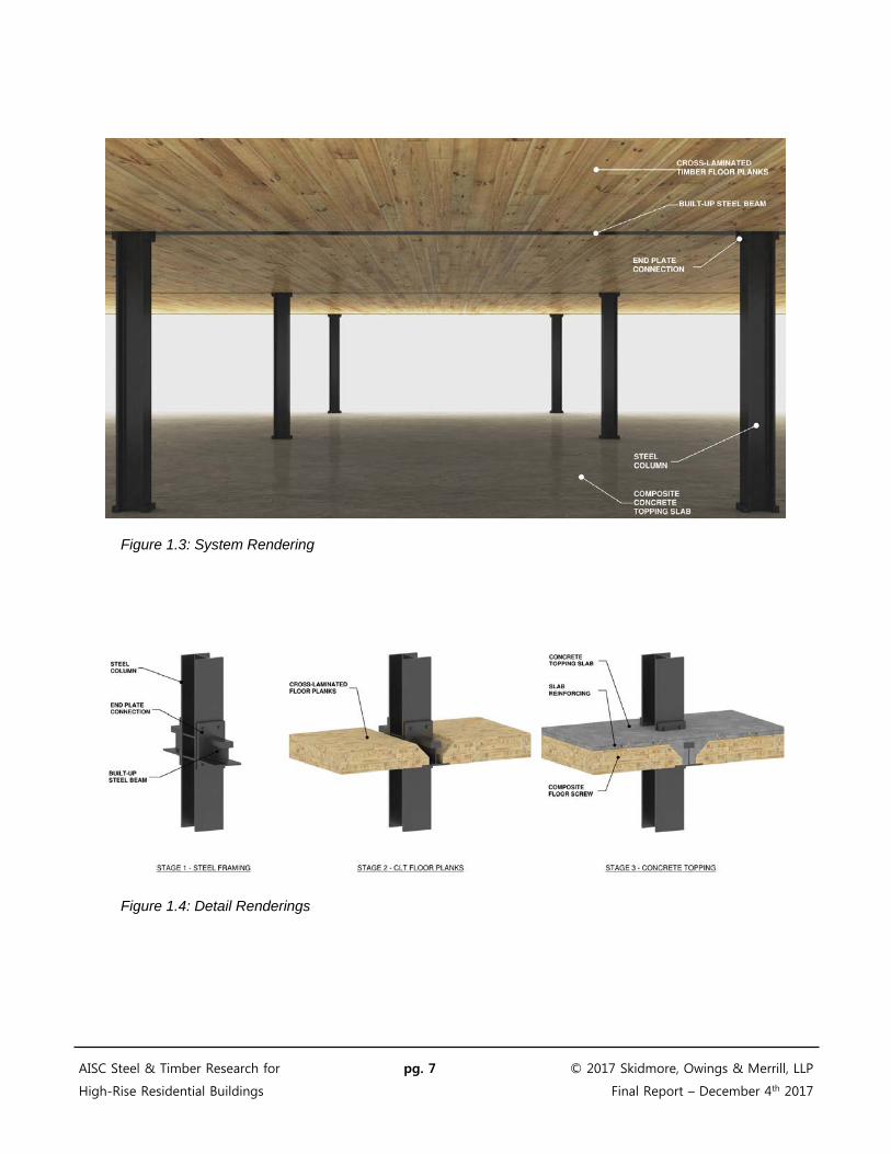
Figure 1.3: System Rendering
Figure 1.4: Detail Renderings
AISC Steel & Timber Research for pg. 7 © 2017 Skidmore, Owings & Merrill, LLP
High-Rise Residential Buildings Final Report – December 4th 2017

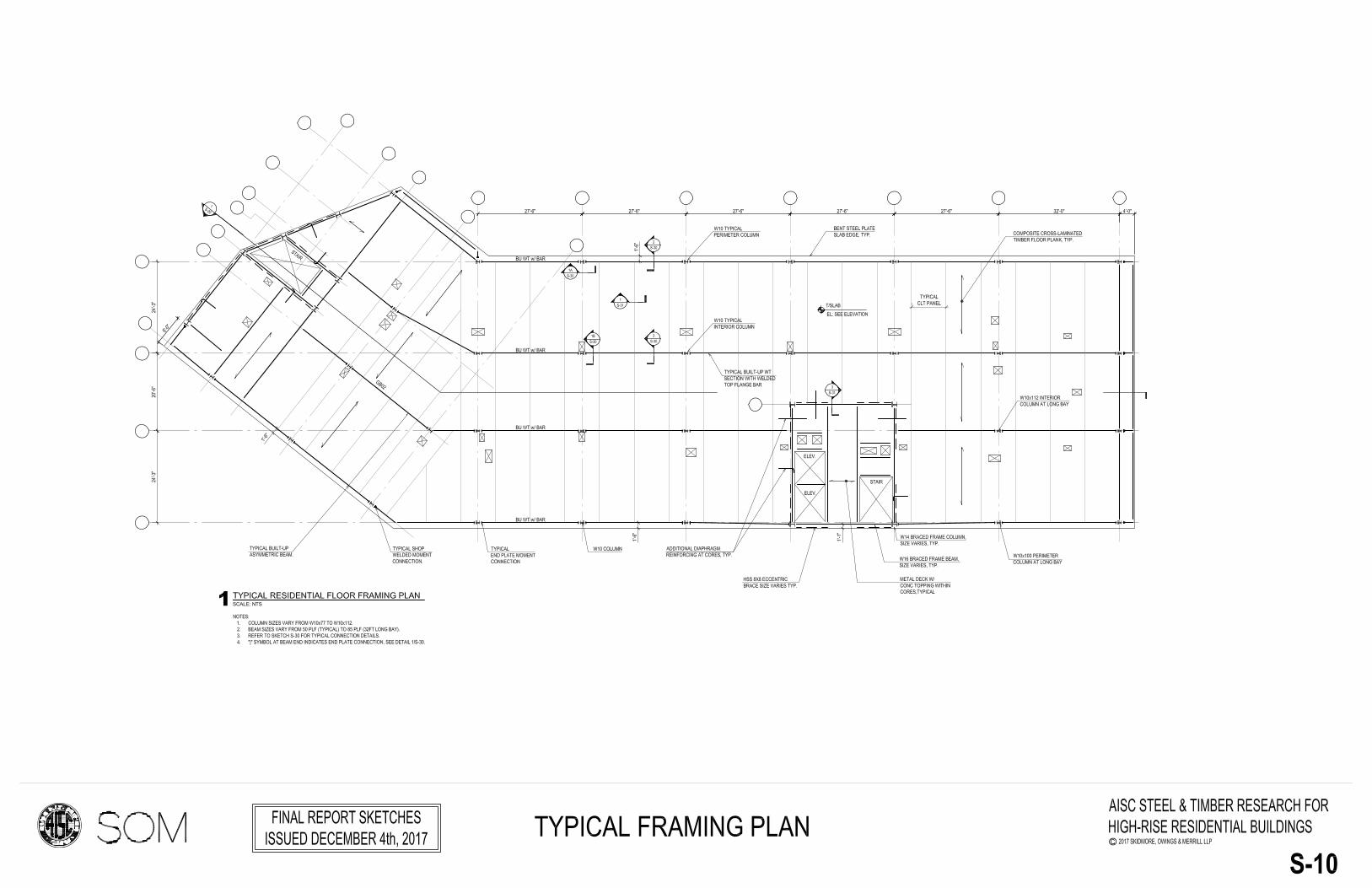
Figure 1.5: Typical Framing Plan
AISC Steel & Timber Research for pg. 8 © 2017 Skidmore, Owings & Merrill, LLP
High-Rise Residential Buildings Final Report – December 4th 2017
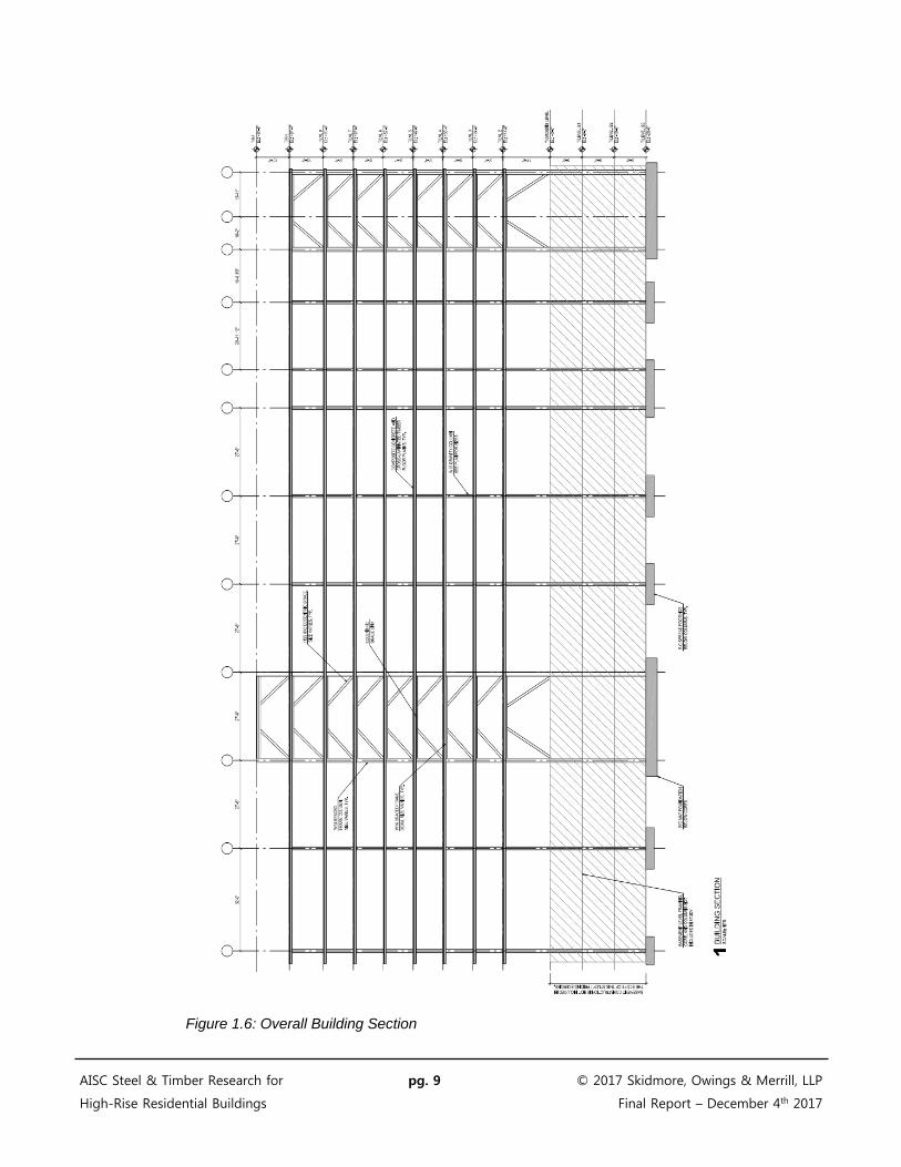
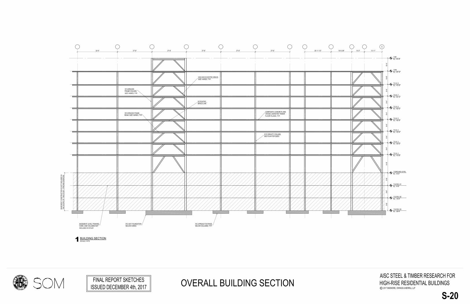
Figure 1.6: Overall Building Section
AISC Steel & Timber Research for pg. 9 © 2017 Skidmore, Owings & Merrill, LLP
High-Rise Residential Buildings Final Report – December 4th 2017

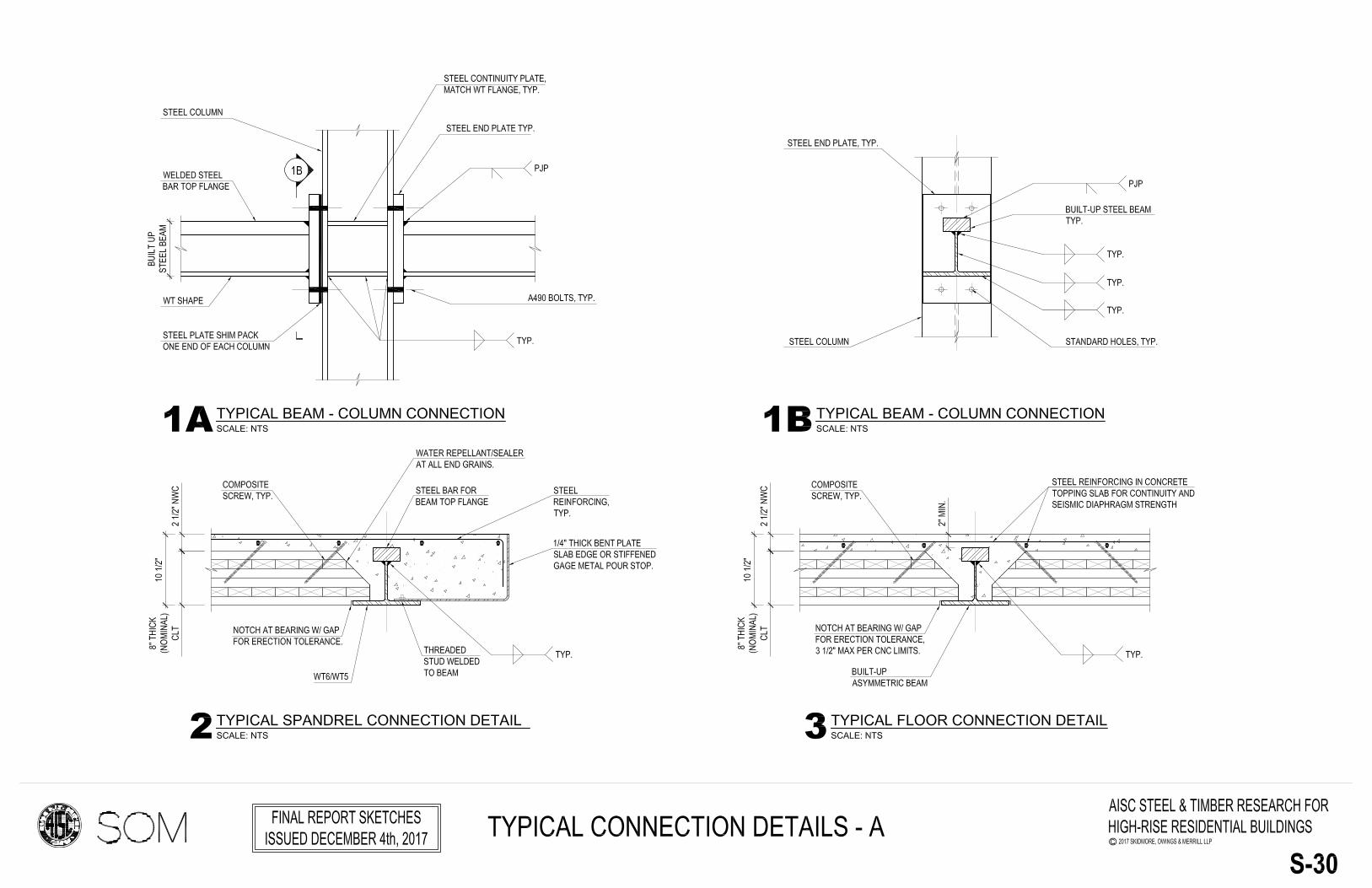
Figure 1.7: Typical Composite Timber Deck and Steel Beam Detail
Figure 1.8: Typical Composite Timber Deck and Spandrel Beam Detail
AISC Steel & Timber Research for pg. 10 © 2017 Skidmore, Owings & Merrill, LLP
High-Rise Residential Buildings Final Report – December 4th 2017
Section 2: System Requirements
2.1 Critical Issues
The benchmark building has typical column bays of 27’-6” by 32’-0” with an 8” thick post-tensioned concrete flat plate. This bay size allows for marketable residential units on typical floors and efficient below grade parking without transferring columns. The 8” flat plate also provides a flat soffit condition which is flexible for unit layouts, service routing, and also minimizes floor-to-floor height. These attributes are seen as key factors for the success of a structural system in the residential market.
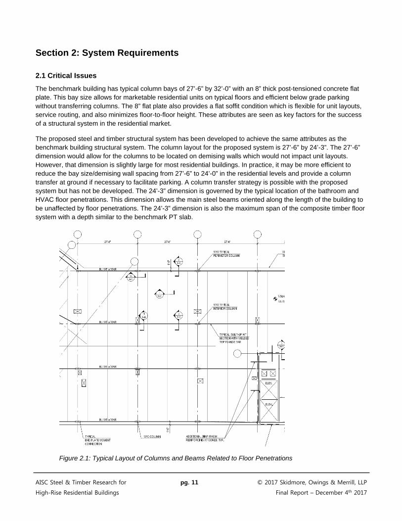
The proposed steel and timber structural system has been developed to achieve the same attributes as the benchmark building structural system. The column layout for the proposed system is 27’-6” by 24’-3”. The 27’-6” dimension would allow for the columns to be located on demising walls which would not impact unit layouts. However, that dimension is slightly large for most residential buildings. In practice, it may be more efficient to reduce the bay size/demising wall spacing from 27’-6” to 24’-0” in the residential levels and provide a column transfer at ground if necessary to facilitate parking. A column transfer strategy is possible with the proposed system but has not be developed. The 24’-3” dimension is governed by the typical location of the bathroom and HVAC floor penetrations. This dimension allows the main steel beams oriented along the length of the building to be unaffected by floor penetrations. The 24’-3” dimension is also the maximum span of the composite timber floor system with a depth similar to the benchmark PT slab.
Figure 2.1: Typical Layout of Columns and Beams Related to Floor Penetrations
AISC Steel & Timber Research for pg. 11 © 2017 Skidmore, Owings & Merrill, LLP
High-Rise Residential Buildings Final Report – December 4th 2017

The total thickness of the composite timber floor system is 10 ½”. This restricts the depth of the asymmetrical steel beam to 8 ½” maximum to allow for 2” of concrete cover over the steel beam and to maintain a flat ceiling soffit. Moment connections will be required at the ends of the steel beams to control deflections for the 27’-6” span and 8.5” maximum depth. Bolted end plate connections have been proposed for economy given the typical nature of the detail. Note that standard design methodologies for end plate moment connections may not be fully applicable for the proposed asymmetric beams. Unusual conditions such as thick and/or narrow top bars may require a special finite element analysis to confirm the strength and stiffness of the connection.
Deeper steel beams which would eliminate the moment connections were considered as part of an initial study, refer to Figure 2.2 for corresponding sizes. The additional depth required to eliminate the moment connections would violate the flat soffit condition and also increase steel tonnage (88plf beams compared to 50plf beams with moment connections). Alternatively, a ceiling could be installed at the lower elevation of the deeper steel beam. The drop ceiling would increase the ceiling sandwich thickness to 14” +/-. This ceiling sandwich thickness would require an additional 6” of floor-to-floor height compared to the concrete flat plate system. This would increase exterior wall and other costs and thus was not developed further at this time.
Figure 2.2: Initial Study of Deeper Beams without Moment Connections
AISC Steel & Timber Research for pg. 12 © 2017 Skidmore, Owings & Merrill, LLP
High-Rise Residential Buildings Final Report – December 4th 2017

2.2 Design Process
The following section outlines the design process and governing criteria for each component of the system as well as overall frame design considerations.
2.2.1 Floor System
The floor system is governed by deflections due to both pre and post-composite conditions for the 24’-3” span. The 8” thick CLT decks are expected to deflect approximately 5/8” under self-weight and the wet weight of the concrete topping slab. It is expected that the decks will be “poured level” by placing up to 1/2" additional concrete thickness at the deck mid-span, resulting in a nearly level floor system. Alternatively, the CLT panels could be cambered by 1/2" in order to avoid additional concrete for leveling. No shoring of the CLT decks is required.
Once the concrete cures the decks become structurally thicker which increases the stiffness. In addition, the continuity of the end connection details change the simple span condition of the floors to a continuous beam condition. These behaviors stiffen the floor system and result in acceptable deflections. The total plus long-term deflection of the floors are approximately 0.7” which is an L/420 deflection after the attachment of partitions.
The deflections of the floor system are considered to be acceptable. Including the deflection of the steel floor beams, the overall bay deflection will be limited to 1.375” (L/240). This floor system has also been evaluated for vibrations and determined to be acceptable.
2.2.2 Gravity Beams
Gravity beams are built up from a steel bar welded to the stem of an inverted WT section forming an asymmetrical shape. As this system gains marketplace acceptance, it is possible that the modified WT section may be rolled by mill producers eliminating the need for additional fabrication and reducing associated costs. The primary design criteria for the beams are listed below:
1) The depth of the beams is limited between 8 inches and 8 ½ inches so that a flat soffit condition can be achieved while providing the necessary concrete cover over the steel beam. The width of the top bars are 4 inches and the bottom WT sections are a maximum of 10 inches wide so that bearing can be provided for the timber deck on the bottom flange with a direct crane placement. The WT width was also selected so that W10 sections can be used as gravity columns. These small columns are advantageous for unit layouts.
2) The steel beams are designed for strength and serviceability requirements under both pre-composite and post-composite stages. In the pre-composite condition where the concrete on top of the timber slab is not cured, the steel beams work alone under structural self-weight and construction live load. In the post-composite condition, the composite steel beams and the concrete topping work together for positive bending moments, and the steel beams and reinforcement bars in the concrete topping work together for negative bending moments.
3) The typical connection between the beams and columns is an end plate moment connection which is bolted to the column flanges. This connection is governed by pre-composite requirements, as the additional reinforcing in the post-composite condition strengthens the connection.
AISC Steel & Timber Research for pg. 13 © 2017 Skidmore, Owings & Merrill, LLP
High-Rise Residential Buildings Final Report – December 4th 2017
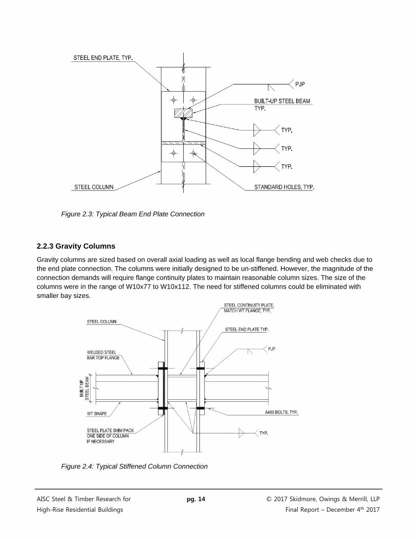
Figure 2.3: Typical Beam End Plate Connection
2.2.3 Gravity Columns
Gravity columns are sized based on overall axial loading as well as local flange bending and web checks due to the end plate connection. The columns were initially designed to be un-stiffened. However, the magnitude of the connection demands will require flange continuity plates to maintain reasonable column sizes. The size of the columns were in the range of W10x77 to W10x112. The need for stiffened columns could be eliminated with smaller bay sizes.
Figure 2.4: Typical Stiffened Column Connection
AISC Steel & Timber Research for pg. 14 © 2017 Skidmore, Owings & Merrill, LLP
High-Rise Residential Buildings Final Report – December 4th 2017
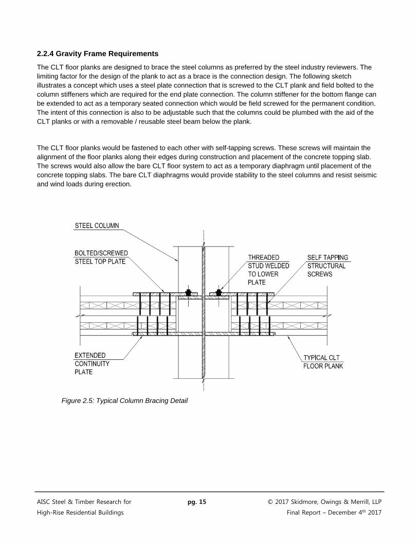
2.2.4 Gravity Frame Requirements
The CLT floor planks are designed to brace the steel columns as preferred by the steel industry reviewers. The limiting factor for the design of the plank to act as a brace is the connection design. The following sketch illustrates a concept which uses a steel plate connection that is screwed to the CLT plank and field bolted to the column stiffeners which are required for the end plate connection. The column stiffener for the bottom flange can be extended to act as a temporary seated connection which would be field screwed for the permanent condition. The intent of this connection is also to be adjustable such that the columns could be plumbed with the aid of the CLT planks or with a removable / reusable steel beam below the plank.
The CLT floor planks would be fastened to each other with self-tapping screws. These screws will maintain the alignment of the floor planks along their edges during construction and placement of the concrete topping slab. The screws would also allow the bare CLT floor system to act as a temporary diaphragm until placement of the concrete topping slabs. The bare CLT diaphragms would provide stability to the steel columns and resist seismic and wind loads during erection.
Figure 2.5: Typical Column Bracing Detail
AISC Steel & Timber Research for pg. 15 © 2017 Skidmore, Owings & Merrill, LLP
High-Rise Residential Buildings Final Report – December 4th 2017
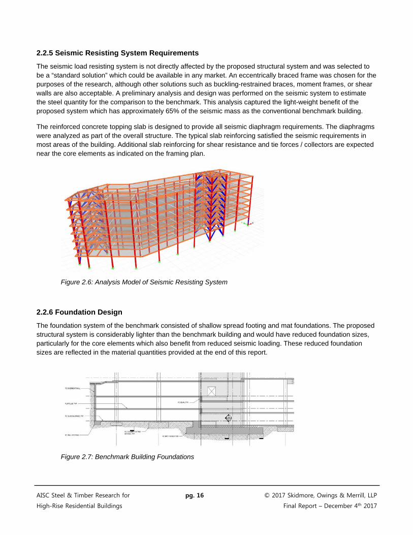
2.2.5 Seismic Resisting System Requirements
The seismic load resisting system is not directly affected by the proposed structural system and was selected to be a “standard solution” which could be available in any market. An eccentrically braced frame was chosen for the purposes of the research, although other solutions such as buckling-restrained braces, moment frames, or shear walls are also acceptable. A preliminary analysis and design was performed on the seismic system to estimate the steel quantity for the comparison to the benchmark. This analysis captured the light-weight benefit of the proposed system which has approximately 65% of the seismic mass as the conventional benchmark building.
The reinforced concrete topping slab is designed to provide all seismic diaphragm requirements. The diaphragms were analyzed as part of the overall structure. The typical slab reinforcing satisfied the seismic requirements in most areas of the building. Additional slab reinforcing for shear resistance and tie forces / collectors are expected near the core elements as indicated on the framing plan.
Figure 2.6: Analysis Model of Seismic Resisting System
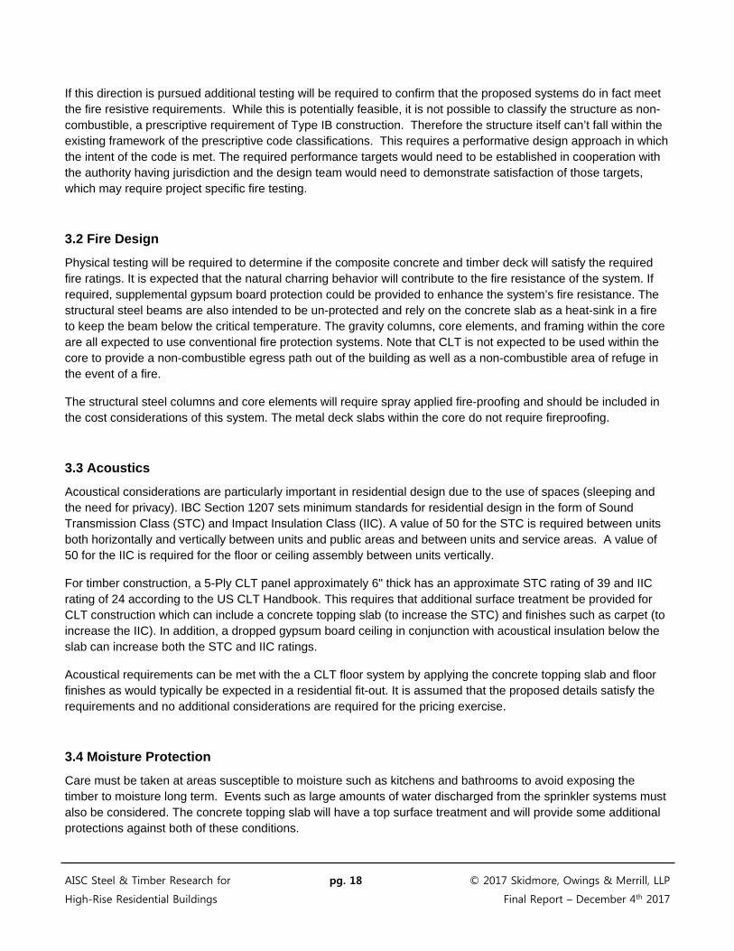
2.2.6 Foundation Design
The foundation system of the benchmark consisted of shallow spread footing and mat foundations. The proposed structural system is considerably lighter than the benchmark building and would have reduced foundation sizes, particularly for the core elements which also benefit from reduced seismic loading. These reduced foundation sizes are reflected in the material quantities provided at the end of this report.
Figure 2.7: Benchmark Building Foundations
AISC Steel & Timber Research for pg. 16 © 2017 Skidmore, Owings & Merrill, LLP
High-Rise Residential Buildings Final Report – December 4th 2017
Section 3: Non-Structural Considerations
3.1 Code Analysis
International Building Code – 2015
Section 310.1 Residential Group R
Section 310.4 Residential Group R-2 Apartment houses
The benchmark building is 9 stories and approximately 92 feet tall. It exceeds the height allowed for combustible or heavy timber construction and the building would have to be categorized as Type IA or IB construction. Both of these require the structural system to be “Non-Combustible.” While this is not possible with timber, the fire resistance requirements of individual elements and types of construction in Type IA or IB could be followed. This can be achieved through a number of strategies including fire resistive coatings or cladding.
Section 602.2 Type IB
Type I and II construction shall consist of noncombustible materials as listed in Table 601, except as permitted in Section 603 and elsewhere in the code.
Table 504.4 Allowable Building Heights and Areas
R-2 Group, Type IB Construction, Sprinklered
Height 160’
Number of Stories 12
Table 506.2 Allowable Area Factor
R-2 Group, Type IB Construction, Sprinklered
Building Area per Story Unlimited
Table 601 – Type IB construction, the major structural elements identified within the code that require fire resistance ratings include:
Primary Structural Frame: 2 hours
Bearing Walls – Interior: 2 hours
Bearing Walls – Exterior: 2 hours
Floor Construction: 2 hours
Roof construction: 1 hour
AISC Steel & Timber Research for pg. 17 © 2017 Skidmore, Owings & Merrill, LLP
High-Rise Residential Buildings Final Report – December 4th 2017
If this direction is pursued additional testing will be required to confirm that the proposed systems do in fact meet the fire resistive requirements. While this is potentially feasible, it is not possible to classify the structure as non-combustible, a prescriptive requirement of Type IB construction. Therefore the structure itself can’t fall within the existing framework of the prescriptive code classifications. This requires a performative design approach in which the intent of the code is met. The required performance targets would need to be established in cooperation with the authority having jurisdiction and the design team would need to demonstrate satisfaction of those targets, which may require project specific fire testing.
3.2 Fire Design
Physical testing will be required to determine if the composite concrete and timber deck will satisfy the required fire ratings. It is expected that the natural charring behavior will contribute to the fire resistance of the system. If required, supplemental gypsum board protection could be provided to enhance the system’s fire resistance. The structural steel beams are also intended to be un-protected and rely on the concrete slab as a heat-sink in a fire to keep the beam below the critical temperature. The gravity columns, core elements, and framing within the core are all expected to use conventional fire protection systems. Note that CLT is not expected to be used within the core to provide a non-combustible egress path out of the building as well as a non-combustible area of refuge in the event of a fire.
The structural steel columns and core elements will require spray applied fire-proofing and should be included in the cost considerations of this system. The metal deck slabs within the core do not require fireproofing.
3.3 Acoustics
Acoustical considerations are particularly important in residential design due to the use of spaces (sleeping and the need for privacy). IBC Section 1207 sets minimum standards for residential design in the form of Sound Transmission Class (STC) and Impact Insulation Class (IIC). A value of 50 for the STC is required between units both horizontally and vertically between units and public areas and between units and service areas. A value of 50 for the IIC is required for the floor or ceiling assembly between units vertically.
For timber construction, a 5-Ply CLT panel approximately 6" thick has an approximate STC rating of 39 and IIC rating of 24 according to the US CLT Handbook. This requires that additional surface treatment be provided for CLT construction which can include a concrete topping slab (to increase the STC) and finishes such as carpet (to increase the IIC). In addition, a dropped gypsum board ceiling in conjunction with acoustical insulation below the slab can increase both the STC and IIC ratings.
Acoustical requirements can be met with the a CLT floor system by applying the concrete topping slab and floor finishes as would typically be expected in a residential fit-out. It is assumed that the proposed details satisfy the requirements and no additional considerations are required for the pricing exercise.
3.4 Moisture Protection
Care must be taken at areas susceptible to moisture such as kitchens and bathrooms to avoid exposing the timber to moisture long term. Events such as large amounts of water discharged from the sprinkler systems must also be considered. The concrete topping slab will have a top surface treatment and will provide some additional protections against both of these conditions.
AISC Steel & Timber Research for pg. 18 © 2017 Skidmore, Owings & Merrill, LLP
High-Rise Residential Buildings Final Report – December 4th 2017

3.5 Exterior Wall
Exterior walls are designed to provide protection from both air and water infiltration. They also insulate the building to minimize the heating and cooling loads which can vary significantly based on the location, context, building type, building systems and material availability. It is important therefore that the main structural system be designed to allow for flexibility in exterior wall types to ensure that no system limitations exist.
Keeping the attachment method back to the base building structure as “conventional” as possible is therefore very important. This will help minimize the potential for any additional connection costs to be added by the contractor responsible for the exterior wall system. In addition, the interface between the exterior wall and the floor slab is critical in that it has to be designed to be flexible to allow for building movement and tolerance but must also be continuous and sealed to restrict the passage of fire and smoke from floor to floor. There are many tested systems for the fire and smoke stop systems, by providing a concrete slab edge condition, the edge is very similar to a conventional steel and composite deck or reinforced concrete building.
Considering the above, the exterior wall should be excluded from the benchmark comparisons as it will be similar.
Figure 3.1: Typical Exterior Wall Detail
AISC Steel & Timber Research for pg. 19 © 2017 Skidmore, Owings & Merrill, LLP
High-Rise Residential Buildings Final Report – December 4th 2017
3.6 Other Non-Structural Systems
The proposed system has been designed to minimize potential impacts to other non-structural trades including the elevators, stairs, and mechanical rooms. These elements will be supported with conventional structural steel framing and composite metal decks, making the support of these elements similar to that in typical high-rise buildings.
AISC Steel & Timber Research for pg. 20 © 2017 Skidmore, Owings & Merrill, LLP
High-Rise Residential Buildings Final Report – December 4th 2017
Section 4: Benchmark Comparison
4.1 Material Take-Offs
Material quantities were calculated for typical above grade floors. Basements are not included as part of the benchmark comparison but have been included in the structural analysis for the design of the foundations to make a comparison against the benchmark building. The total framed area to be compared is 140,000ft2 (8 stories in total). The superstructure and foundation material quantities provided below are to be applied against the total framed area.
4.1.1 Proposed Structural System
Superstructure
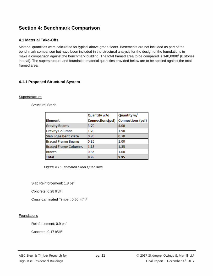
Structural Steel:
Figure 4.1: Estimated Steel Quantities
Slab Reinforcement: 1.8 psf
Concrete: 0.28 ft3/ft2
Cross-Laminated Timber: 0.60 ft3/ft2
Foundations
Reinforcement: 0.9 psf
Concrete: 0.17 ft3/ft2
AISC Steel & Timber Research for pg. 21 © 2017 Skidmore, Owings & Merrill, LLP
High-Rise Residential Buildings Final Report – December 4th 2017

4.1.2 Benchmark Building
Superstructure
Reinforcing: 5.50 psf
Post-Tensioning Tendons: 1.10 psf
Concrete: 0.90 ft3/ft2
Foundations
Reinforcement: 1.7 psf
Concrete: 0.30 ft3/ft2
AISC Steel & Timber Research for pg. 22 © 2017 Skidmore, Owings & Merrill, LLP
High-Rise Residential Buildings Final Report – December 4th 2017

4.2 Cost and Schedule Considerations
The viability of the proposed system will vary based on project specific requirements and on local market conditions. Building developers, designers, and contractors should consider a whole building cost model including schedule when considering the proposed system. The cost and schedule items below have been developed to aid the costing of this system compared to conventional reinforced concrete systems for a building of similar size and project constraints. The actual costing of the system for a project will be the responsibility of the Project Team.
Shallow Foundations
The foundation costs need to consider the savings in excavated materials due to smaller foundation elements as well as the savings in concrete and reinforcing. Schedule savings must also be considered and are noted in the project schedule section.
• Excavation • Concrete • Reinforcing
Steel Framing
• Material • Fabrication
o Include asymmetric beams and end plates o Include straightening of asymmetric beams if required o Include bent plates or other edge of slab details o Include typical framing and metal decks within core areas
• Shipping • Erection
o Include considerations for end plate fit-up o Include sequencing with CLT decking
CLT Decking
The CLT decking should consider availability of material, delivery, and site storage logistics.
• Material o Include CLT o Include End Grain Sealer o Include Typical Fasteners o Include Composite Connectors
• Fabrication o Include CNC routing of panel ends, bearing notches, end grain sealers
• Shipping • Erection
o Confirm Erection by Steel Erector o Include Fastener Installation o Include Composite Connector Installation
Concrete Topping
• Concrete Material • Reinforcing • Placement and Finishing
AISC Steel & Timber Research for pg. 23 © 2017 Skidmore, Owings & Merrill, LLP
High-Rise Residential Buildings Final Report – December 4th 2017
Lateral Load Resisting System
If the selected system matches the conventional system being compared (such as RC shear walls), consider the impact of the lower weight and seismic loads.
• Reduced seismic mass, 65% of concrete baseline
Fireproofing
The system has been designed so that the CLT and steel beams may not require fireproofing. This will need to be confirmed by testing. If confirmed, this will reduce the fireproofing requirements to the columns only.
• Column Fire Proofing
Non-Structural Attachments
Include considerations for un-shored construction (early floor open for non-structural trades). Include considerations for attachment to deck without post-tensioning, more economical fasteners to CLT.
• Un-shored construction • Attachments
Finishing Credits
The CLT soffit has the advantage of being the finished material if selected. Consider the cost savings of the exposed CLT soffit if selected.
• Soffit finishing consideration
Project Schedule
The following schedule considerations should be included as appropriate for a project:
• Early foundation completion • Prefabricated Steel and CLT framing erection • Un-shored construction • Early building opening revenue
Whole Building Cost Comparison
Once the proposed composite steel and CLT system is priced as part of the whole building cost, compare it against the whole building cost utilizing conventional structural systems:
• Conventional Structural System: • Proposed Steel and CLT System:
AISC Steel & Timber Research for pg. 24 © 2017 Skidmore, Owings & Merrill, LLP
High-Rise Residential Buildings Final Report – December 4th 2017
Section 5: Verification Requirements
5.1 Testing
Sections 2 and 3 of this report outline the system performance requirements which include structural behavior, fire resistance, acoustics, and durability. Some of these aspects will require physical testing to support a performative design of the system within the existing framework of the building code. The following types of tests are recommended and could be part of a project specific testing program. Note that some testing may overlap with general testing requirements for composite CLT and concrete floor systems, which may not be shown below.
Structural
• Test connection of CLT to asymmetric steel beam for continuous bending behavior • Test seismic diaphragm performance of the composite CLT floor system • Test asymmetric beam for composite action with slab through concrete bond • Test steel beam end connection for negative bending strength and stiffness with slab reinforcing • Test the CLT and steel connections for seismic drift compatibility
Fire
• Test composite CLT floor system for fire resistance • Test unprotected steel floor beam for fire resistance
Acoustics
• Test composite CLT floor system for acoustic performance including STC and IIC
Durability
• Test composite CLT floor system for long-term durability and moisture resistance
AISC Steel & Timber Research for pg. 25 © 2017 Skidmore, Owings & Merrill, LLP
High-Rise Residential Buildings Final Report – December 4th 2017

Section 6: Conclusions
The goal of the research project was to determine the viability of the proposed structural system in the high-rise residential building market. The viability of the system will depend on its ability to support marketable and serviceable residential units, efficiency of construction, and overall project cost. These issues have been evaluated and the following conclusions have been drawn:
1. Marketability
a. Bay Sizes. The bay size studied was 27’-6” x 24’-3”. The proposed system can achieve this bay size which is larger than required for many markets. If possible, the bay size could be decreased for further economy of the system.
b. Flat Soffits. The proposed system achieves a flat soffit condition which simplifies unit services and partition head details. This attribute is consistent with concrete flat plate construction.
c. Ceiling Sandwich/Thickness. The solid floor construction of 10 ½” thick is slightly thicker than most 8” thick concrete flat plate buildings. This may impact floor to floor heights slightly.
d. Floor Penetrations. Floor penetrations can be located anywhere except for steel framing lines. Floor penetrations can be pre-fabricated in the timber decks or installed in the field for out-of-sequence unit planning.
e. Exterior Wall. The system is capable of supporting any type of exterior wall.
2. Serviceability a. Deflections & Vibrations. The system is governed by deflections. Pre-composite deflections will
likely govern the overall sizes due to the un-shored construction. The total plus long term deflections will be similar to a conventional concrete flat plate system.
b. Acoustics. The system is expected to achieve an STC and IIC of 50 due to the concrete topping slab and flooring systems over the concrete (carpeting, hard wood over acoustic mat, etc.)
c. Fire protection. The floor system is intended to achieve the necessary fire ratings through passive behaviors. Encapsulation of the steel and timber could be used to enhance the natural fire resistance of the system and will need to be determined by fire testing.
d. Durability. The durability of the floor system is expected to exceed the useful life of the structure. The durability enhancement of the concrete topping slab is a key feature in achieving this goal.
3. Construction
a. Prefabricated. The steel and mass-timber building elements are prefabricated and can be constructed faster than a concrete framed building. This benefit can save cost by reducing the construction schedule and increase revenues with a faster time to market.
b. Lightweight. The weight of the system is approximately 65% of a comparable concrete framed building. This reduces foundation costs, seismic loading, and construction time.
4. Cost
c. Material Quantities. The estimated material quantities show that the proposed structure is efficient when considering the large bay sizes, flat soffit condition, and high seismic location.
d. Preliminary Pricing. Pricing information received suggests that the cost for the system would be comparable to a concrete framed structure (within 10%), depending on project specifics and current market conditions.
AISC Steel & Timber Research for pg. 26 © 2017 Skidmore, Owings & Merrill, LLP
High-Rise Residential Buildings Final Report – December 4th 2017

The proposed steel and timber system achieves marketable bay sizes, a flat soffit condition, and a thin ceiling sandwich. This is achieved with reasonable material quantities, fabrication techniques, and erection sequences. The proposed system also has clear advantages due to its lightweight and prefabricated construction. Initial pricing information received from contractors reviewing the system suggest that it could compete financially with conventional systems. The actual cost of the system will depend on the project specifics and market conditions.
This report shows that the system could be viable in the high-rise residential building market. The viability of the system will need to be confirmed by early-adopter projects. Building developers, designers, and contractors are encouraged to review the advantages of the proposed system and to consider steel framing for high-rise residential buildings.
AISC Steel & Timber Research for pg. 27 © 2017 Skidmore, Owings & Merrill, LLP
High-Rise Residential Buildings Final Report – December 4th 2017
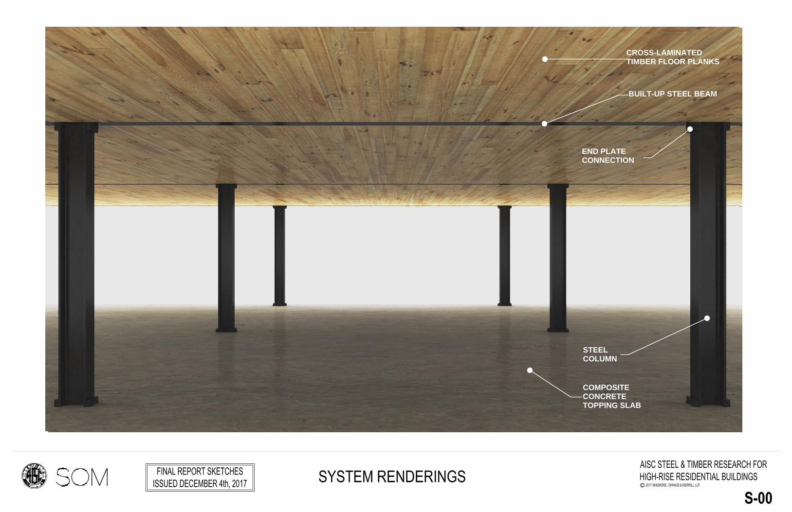
CROSS-LAMINATEDTIMBER FLOOR PLANKS
BUILT-UP STEEL BEAM
END PLATECONNECTION
STEELCOLUMN
COMPOSITECONCRETETOPPING SLAB
CROSS-LAMINATEDTIMBER FLOOR PLANKS
BUILT-UP STEEL BEAM
END PLATECONNECTION
STEELCOLUMN
COMPOSITECONCRETETOPPING SLAB

STAGE 1 - STEEL FRAMING STAGE 2 - CLT FLOOR PLANKS STAGE 3 - CONCRETE TOPPING
STEELCOLUMN
END PLATECONNECTION
BUILT-UPSTEEL BEAM
CROSS-LAMINATEDFLOOR PLANKS
CONCRETETOPPING SLAB
SLABREINFORCING
COMPOSITEFLOOR SCREW