Embed Size (px)
Citation preview

Virginia Tech 1 of 24
Airport Runway Location and Orientation
CEE 4674 Airport Planning and Design
Dr. Antonio A. Trani Professor of Civil Engineering
Virginia Tech

Virginia Tech 2 of 24
Runway Location Considerations
The following factors should be considered in locating and orienting a runway:
• Wind
• Airspace availability
• Environmental factors (noise, air and water quality)
• Obstructions to navigation
• Air traffic control visibility
• Wildlife hazards
Read Chapter 2 of FAA AC/150-5300-13 for more information about each topic

Virginia Tech 3 of 24
Runway Orientation and Wind
• The orientation of the runway is an important consideration in airport planning and design
• The goal of this exercise is to define the runway orientation that maximizes the possible use of the runway throughout the year accounting for a wide variety of wind conditions
• FAA and ICAO regulations establish rules about runway orientation and their expected coverage
• Ideally, all aircraft operations on a runway should be conducted against the wind
• Unfortunately, wind conditions vary from hour to hour thus requiring a careful examination of prevailing wind conditions at the airport site

Virginia Tech 4 of 24
Cross Wind Operations
All aircraft have maximum demonstrated cross wind components (usually specified in the flight manual)
RunwayWind vector
Aircraft VelocityVector
Resulting AircraftGround Speed
Vector
Crosswind Component
Wind vector
Virginia Tech 5 of 24
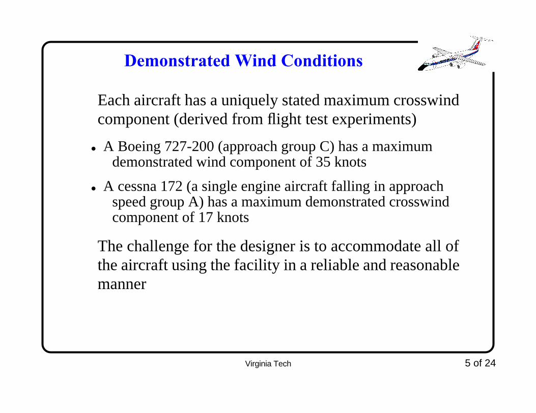
Demonstrated Wind Conditions
Each aircraft has a uniquely stated maximum crosswind component (derived from flight test experiments)
• A Boeing 727-200 (approach group C) has a maximum demonstrated wind component of 35 knots
• A cessna 172 (a single engine aircraft falling in approach speed group A) has a maximum demonstrated crosswind component of 17 knots
The challenge for the designer is to accommodate all of the aircraft using the facility in a reliable and reasonable manner

Virginia Tech 6 of 24
Reporting Wind Conditions
Wind is reported on an azimuthal basis as shown belowNorth
EastWest
South(180o)
(90o)
(0o)
(270o)
45o
Wind from 315o
w =15 knots
at 15 knots
Virginia Tech 7 of 24
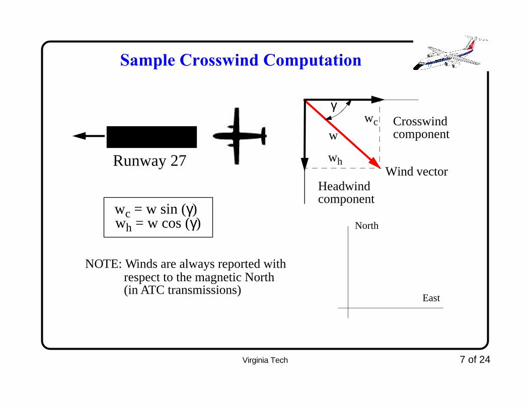
Sample Crosswind Computation
Wind vectorRunway 27
γ
w
wc = w sin (γ)
Crosswindcomponent
Headwindcomponent
wc
wh
North
East
wh = w cos (γ)
NOTE: Winds are always reported withrespect to the magnetic North(in ATC transmissions)
Virginia Tech 8 of 24
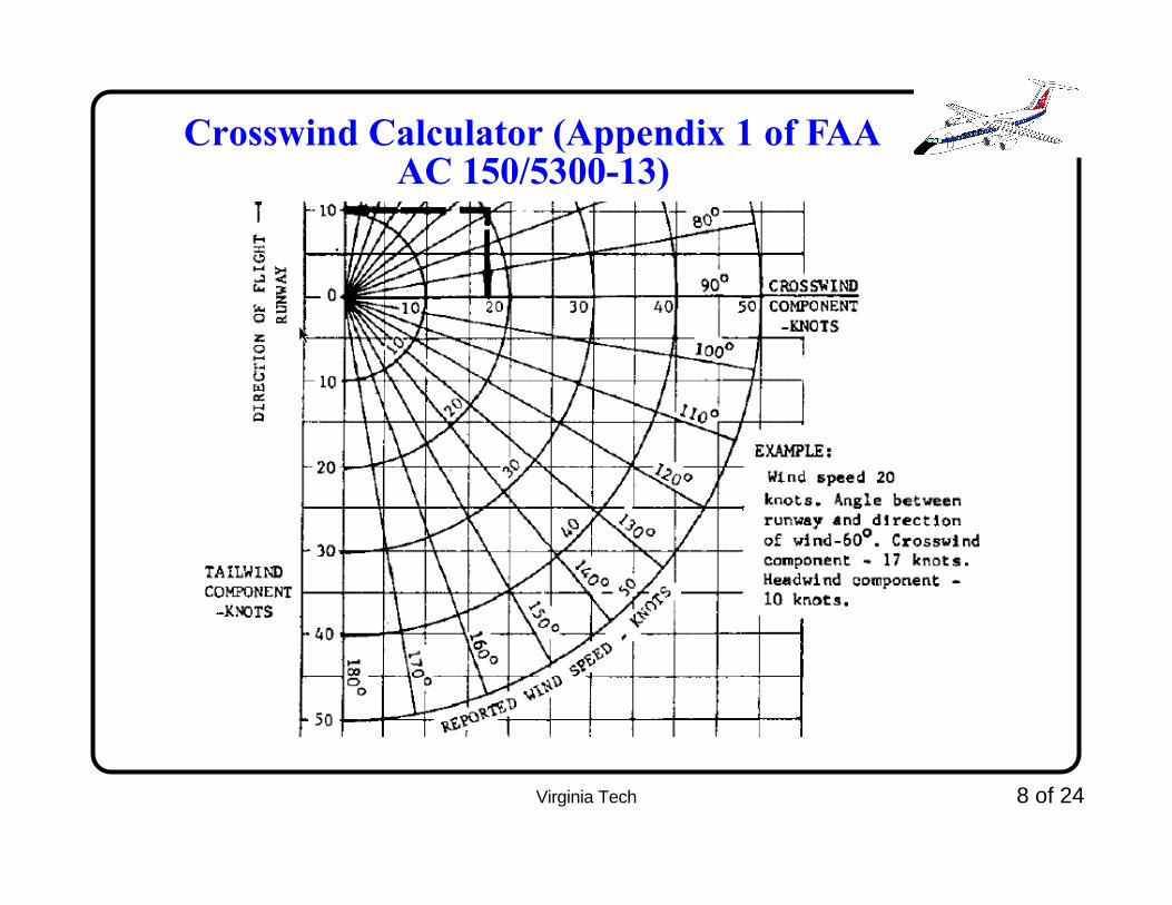
Crosswind Calculator (Appendix 1 of FAA AC 150/5300-13)

Virginia Tech 9 of 24
Design Criteria (FAA and ICAO)
Read Chapter 2 of FAA AC 150/5300-13 or Aerodrome design manual (Volume 1 for ICAO standards)
Employ the most critical aircraft expected to operate in the airfield (in this context the most critical is the largest
• Provide a runway (or runways) orientation that satisfies 95% coverage (i.e., crosswinds below a critical value) considering yearly wind conditions
• If one runway does not meet the 95% criteria design a second crosswind runway
The argument of using the most critical aircraft might sound counterintuitive (but it is necessary)

Virginia Tech 10 of 24
FAA Crosswind Design Criteria
Recognizing that each aircraft has unique maximum demonstrated crosswind characteristics the FAA (and ICAO as well) set a low value for crosswind design criteria
Airport Reference Code Design Crosswind Value (knots)
A-I and B-I 10.5
A-II and B-II 13.0
A-III, B-III and C-I through D-III 16.0
A-IV through D-IV 20.0

Virginia Tech 11 of 24
ICAO Crosswind Design Criteria
Similar to the FAA criteria in many ways. However, ICAO has two aerodrome classifications.
Aerodrome Runway Reference Code
Runway Reference Field Length (m.)
A < 800
B 800 - 1,200
C 1,200 - 1,800
D > 1,800

Virginia Tech 12 of 24
ICAO Crosswind Design Criteria
Similar to the FAA criteria in many ways but simpler (only three design values).
Runway Length (m.) Design Crosswind Value (knots)
< 1,200 10.0
1,200 - 1,500 13.0
> 1,500 20.0

Virginia Tech 13 of 24
Data Sources
Collect wind data from a reliable source:
• National Oceanic and Atmospheric Administration (NOAA), Environmental Data Service (EDS)
• The EDS's National Climatic in Asheville, North Carolina
• The wind data is usually available for hundreds of stations across the U.S.
• Ironically, Blacksburg has a National Weather Service station but EDS does not have a record of us!
• Carefully use weather record from two or more nearby stations if wind data is not readily available at the proposed airport site (be very careful of local weather effects)

Virginia Tech 14 of 24
Data Sources
• For mountainous terrain with data without wind data, the use of nearby stations is of questionable value
• Take one year of wind data if possible
• Several automated reporting systems exist at airport that can be used for this purpose (EDS will not have data about these)
AWOS - Automated Weather Observation System
• The data available from NOAA usually includes 10-15 years (daily observations)
• Use 5-10 years of data for airport planning purposes (except when you are collecting the data yourself)
Virginia Tech 15 of 24
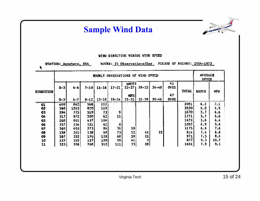
Sample Wind Data

Virginia Tech 16 of 24
Wind Rose Analysis
• A clever way to portray all wind data in agraphical template and estimate the percent runway coverage
• The wind rose is just a graphical way to add decompose vectors
• The wind rose is populated with percentages derived from wind observations
• You can build a wind rose with a piece of cardboard and a transparent template

Virginia Tech 17 of 24
Wind Rose TemplateEnter percentagesin each cell
Each cellrepresentsa wind directionand magnitude

Virginia Tech 18 of 24
Sample Wind Rose with Data84.1%winds
< 10 knots
Virginia Tech 19 of 24
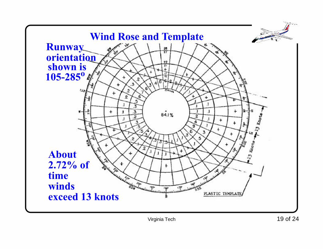
Wind Rose and Template
About2.72% oftimewindsexceed 13 knots
Runwayorientation
105-285oshown is
Virginia Tech 20 of 24
Use of FAA Computer Program (AD42.exe)
The FAA computer program companion to the AC 5300-13 can be used to study runway orientation coverages
It requires a text file in a very specific format that contains number of wind observations from various azimuths and winds speeds (similar to the wind rose template)
Virginia Tech 21 of 24
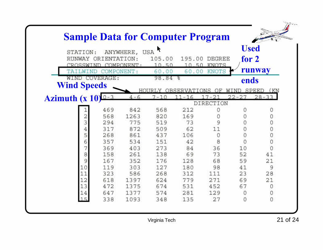
Sample Data for Computer Program
Wind SpeedsAzimuth (x 10)
Usedfor 2runwayends

Virginia Tech 22 of 24
Sample Output of AD42.exe ProgramSampleresultfor2 runways
Primaryrunway
Crosswindrunway
Virginia Tech 23 of 24
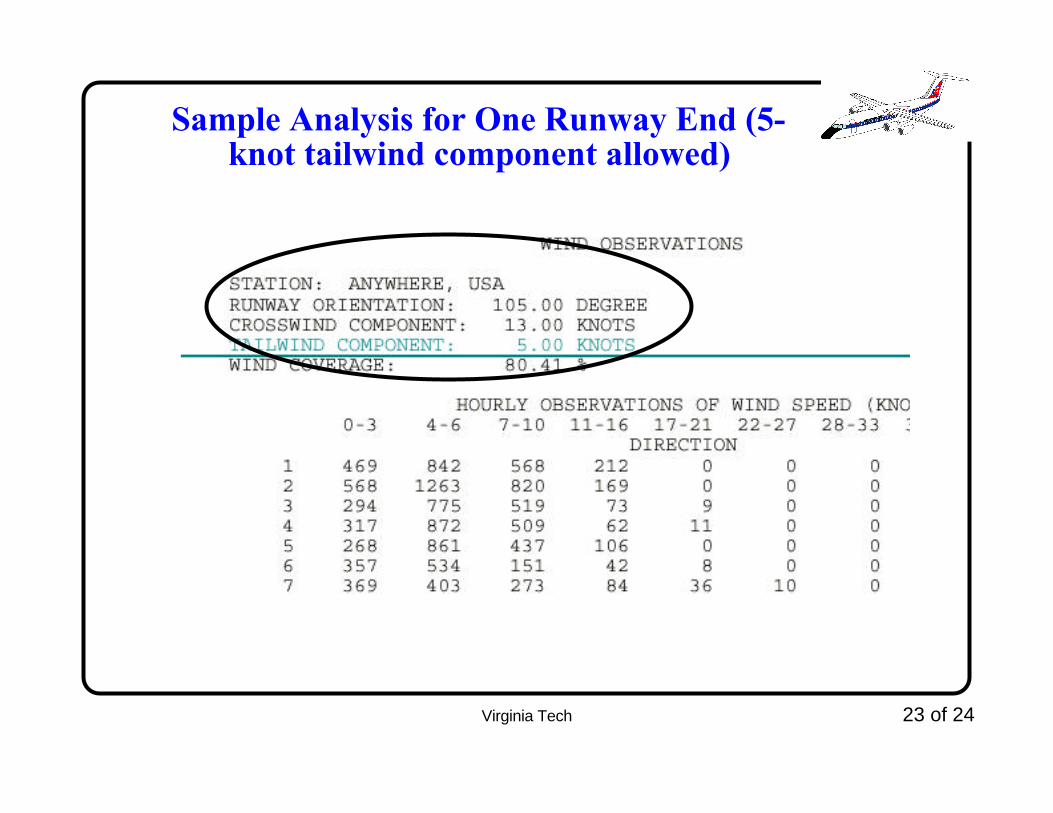
Sample Analysis for One Runway End (5-knot tailwind component allowed)
Virginia Tech 24 of 24
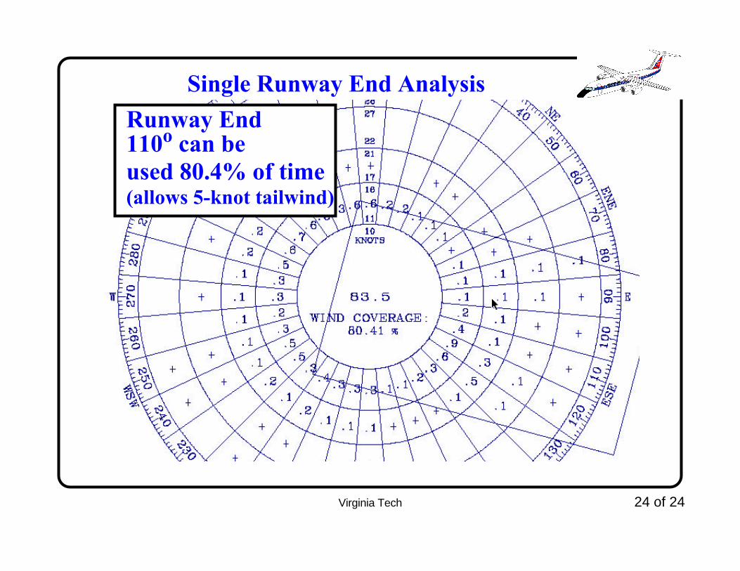
Single Runway End AnalysisRunway End110o can beused 80.4% of time(allows 5-knot tailwind)

Virginia Tech - Air Transportation Systems Laboratory
Runway Orientation: Extras
CEE 4674Analysis of Air Transportation Systems
Dr. Antonio A. TraniProfessor

Virginia Tech - Air Transportation Systems Laboratory
Explanation About Tailwind Allowances
• Aircraft are expected to land and takeoff against the wind
• Under some conditions, pilots are allowed to operate with a small tailwind component
• The amount of tailwind varies from airline to airline but is seldom more than 8 knots (relatively small winds)
• Implications of taking off with tailwinds
• longer runway length
• Implications of landing with tailwinds
• Faster approach speeds (i.e., ground speed)
• Longer landing runway requirements
25

Virginia Tech - Air Transportation Systems Laboratory
Reasons for Tailwind Allowances
• Pilot prefers to use a higher precision approach by taking a small tailwind
• Busan (Korea) accident (http://aviation-safety.net/database/record.php?id=20020415-0)
• Kingston, Jamaica
• Terrain in one of the approach forces a pilot to take a small tailwind
• For Design of Runway Orientation;
• Use 5 knots of tailwind to estimate the percent of time a runway end is used.
26
Virginia Tech - Air Transportation Systems Laboratory
Example Problem
• Design the optimal runway orientation for an airport using FAA airport design code D-V
• Use the default data in FAA program AD42.exe downloaded from the web site
• Solution:
• Step 1: determine the design crosswind component
• D-V requires 20 knots of cross wind component (see FAA AC 150/5300-13)
27

Virginia Tech - Air Transportation Systems Laboratory
Example Problem (cont.)• Step 2:
• Use the FAA AD42.exe program or use the Java tool available at the FAA GIS website
• This steps requires that you estimate the percent coverage for each runway orientation.
• Step 3:
• Find the new coverage for each new runway orientation (say every 5 degrees)
• Create a plot with coverage vs runway orientation
• Step 4:
• Select the runway orientation that provides the highest coverage
28
Virginia Tech - Air Transportation Systems Laboratory
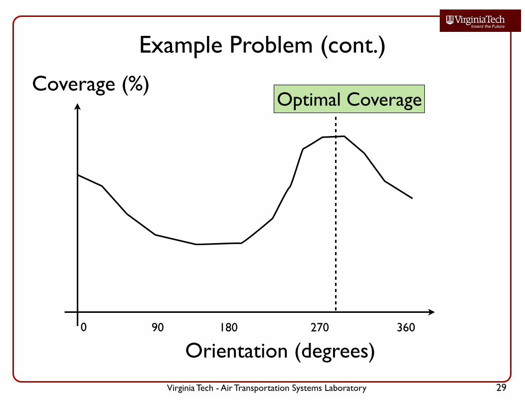
Example Problem (cont.)
Orientation (degrees)
Coverage (%)
0 90 180 270 360
Optimal Coverage
29
Virginia Tech - Air Transportation Systems Laboratory
Example Problem (cont.)
• Step 5:
• Check is the coverage meets the 95% criteria required by FAA and ICAO
• If the 95% is met you are done
• Otherwise add a second (crosswind) runway repeating steps 1-4 until the 95% criteria is achieved
30

Virginia Tech - Air Transportation Systems Laboratory
When Do I use a 60 knot Tailwind in the FAA AD42.exe Program?
• When you wan to know the percent of time a runway is used from both runway ends, use an artificially high value of tailwind
• This tells you in one step the percent of time the runway is usable from both approaches
31

Virginia Tech - Air Transportation Systems Laboratory
Wind Rose Java Tool at FAA Website • Available at: https://airports-gis.faa.gov/
airportsgis/publicToolbox/windroseForm.jsp
32
Virginia Tech - Air Transportation Systems Laboratory
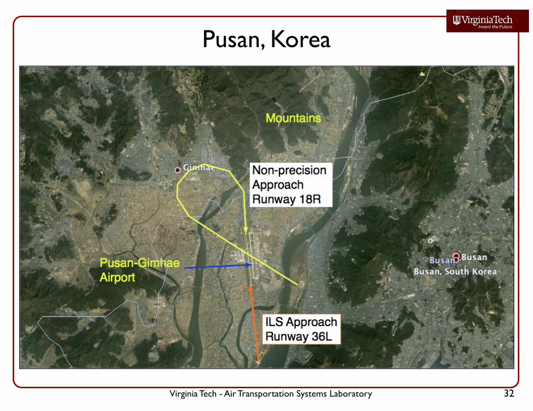
Pusan, Korea
32


![New Member Orientation [Insert Club Name Here]. 2Lions Clubs InternationalNew Member Orientation New Member Orientation Summary New member orientation](https://img.pdfslide.us/doc/110x75/551aa195550346e0158b5933/new-member-orientation-insert-club-name-here-2lions-clubs-internationalnew-member-orientation-new-member-orientation-summary-new-member-orientation.jpg)