Embed Size (px)
Citation preview
Graco, Inc. P.O. Box 1441 Minneapolis, MN 55440-1441 ©1995 Graco Inc. Form No. 300-071R5 6/95 Rev 2 SL Training 11/14
Airless Spray Techniques Concept and Theory
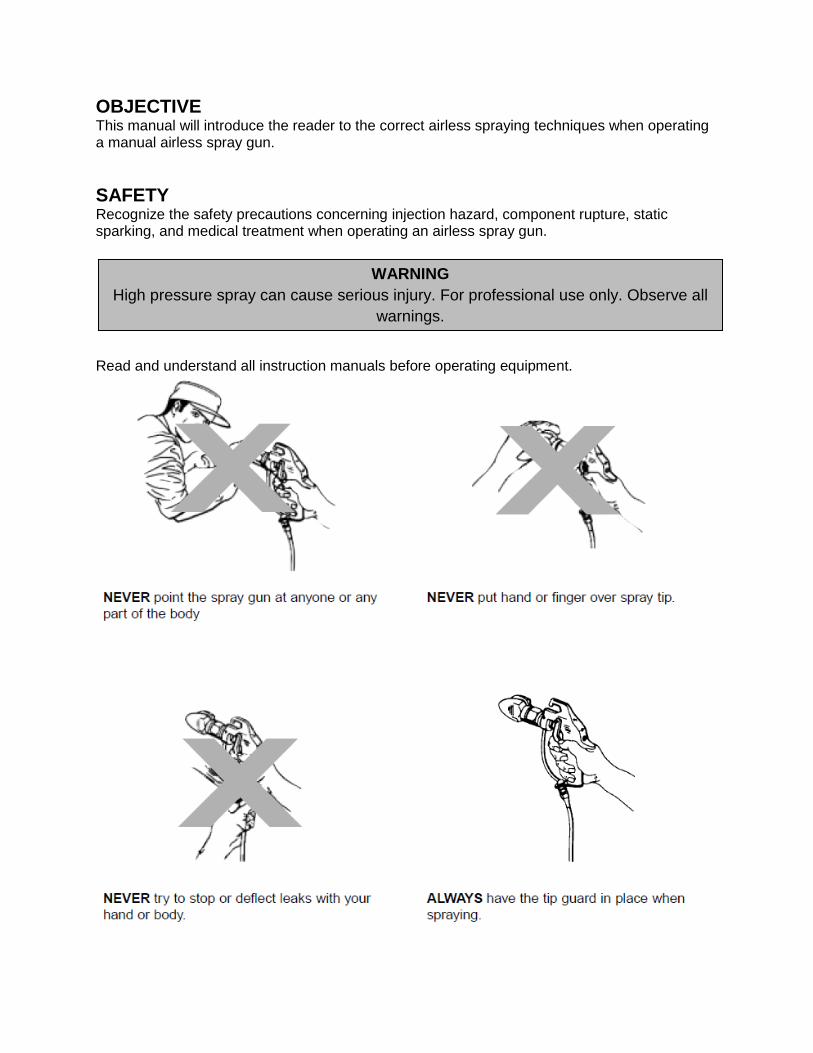
OBJECTIVE This manual will introduce the reader to the correct airless spraying techniques when operating a manual airless spray gun.
SAFETY Recognize the safety precautions concerning injection hazard, component rupture, static sparking, and medical treatment when operating an airless spray gun. Read and understand all instruction manuals before operating equipment.
WARNING
High pressure spray can cause serious injury. For professional use only. Observe all
warnings.

I. AIRLESS BASICS Definition of Airless Spray: Airless spray is a method of atomizing paint without the use of compressed air. The paint is pumped under high pressure through a supply line to an airless gun. The paint is forced at high pressure through a small opening at the front of the valve, called the orifice, or spray tip. The tip restriction (orifice) forms a spray pattern. The break-up of material into small droplets is called atomization.
Figure 1 Water System
Figure 2 Basic Airless System
Figures 1 and 2 show the similarity between a simple water system and a basic airless system.
Advantages of Airless Spray
1. Airless has less overspray or “bounce back” of material than air spray.
2. More efficient than conventional spray. Airless has transfer efficiency of 60% to 90%.
3. A thicker coat of material can be applied in a single pass. With the high pressure of
airless spray, high viscosity materials can be atomized without costly solvent reduction.
4. Airless accommodates faster production line speeds. More paint can be applied at a
heavier mil thickness.
5. Good penetration can be attained on recessed areas of work pieces.
II. ADJUSTMENTS The key factor to good atomization is the coating flow rate. Flow rate is controlled by the spray tip size and the pump. The spray tip orifice size also determines the spray pattern size and the range of atomization. NOTE: The airless supply pump must be the proper size to supply the required flow rate to one or more multiple airless spray guns at a given spray pressure.
Atomization There are two adjustments that can be made on an airless system once the tip has been selected:
Material Viscosity
System Pressure
Viscosity The viscosity of paint can be lowered either by adding solvents or heating. Lower viscosity will almost always produce a finer atomization.
Pressure The pressure can be adjusted in an airless system to achieve the best atomization possible. The fluid pressure needed will vary based on the viscosity of the material. To adjust the pressure, increase the pressure gradually at the system’s fluid regulator until a full elliptically shaped cone spray pattern is formed. Use the least amount of atomization fluid pressure possible to attain the best possible pattern.
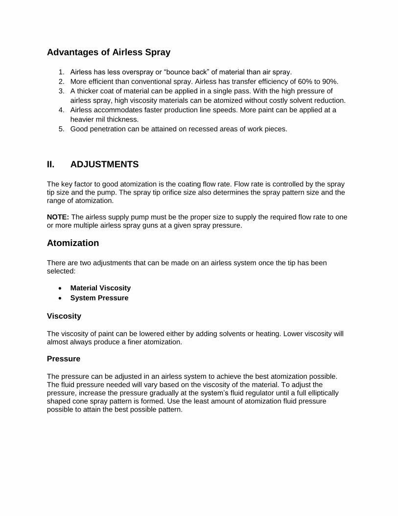
Pattern Size The mil thickness of the coating on the work piece is controlled by both the orifice size and the fan angle. Increase the orifice size, but leave the fan size the same and the thickness of paint will increase (see Figure 3).
Figure 3 Larger Orifice and Same Size Fan
Keep the orifice opening the same, but increase the fan width and the thickness of paint will decrease (see Figure 4).
Figure 4 Large Fan Same Size Orifice
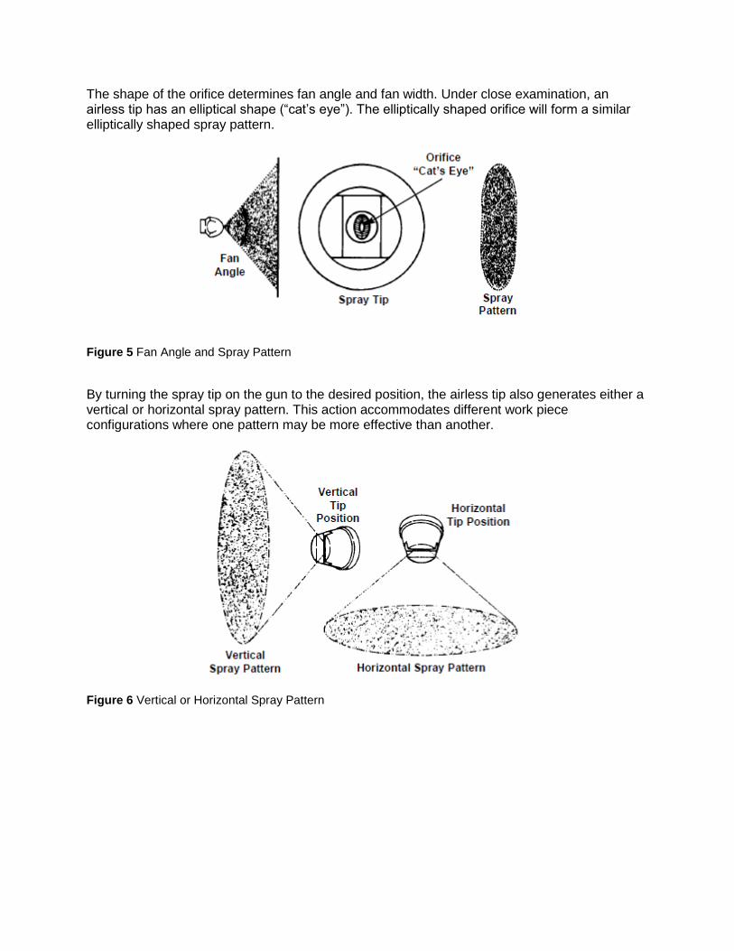
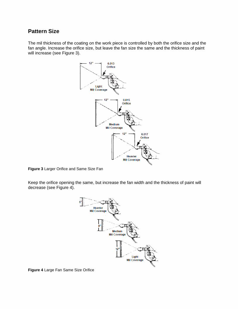
The shape of the orifice determines fan angle and fan width. Under close examination, an airless tip has an elliptical shape (“cat’s eye”). The elliptically shaped orifice will form a similar elliptically shaped spray pattern.
Figure 5 Fan Angle and Spray Pattern
By turning the spray tip on the gun to the desired position, the airless tip also generates either a vertical or horizontal spray pattern. This action accommodates different work piece configurations where one pattern may be more effective than another.
Figure 6 Vertical or Horizontal Spray Pattern
III. SPRAY TECHNIQUES In any airless spray application, a careful study to determine correct spray techniques for each work piece configuration can save both time and material. Section III divides spray techniques into three separate areas as follows:
Operator Technique
Gun Position and Movement
Work Piece Configuration
A balanced combination of these three factors will generate the best finish quality, with the least effort and lowest cost.
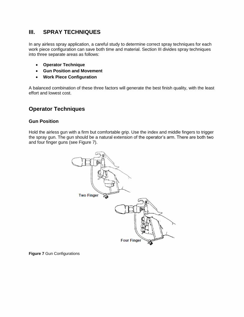
Operator Techniques Gun Position Hold the airless gun with a firm but comfortable grip. Use the index and middle fingers to trigger the spray gun. The gun should be a natural extension of the operator’s arm. There are both two and four finger guns (see Figure 7).
Figure 7 Gun Configurations
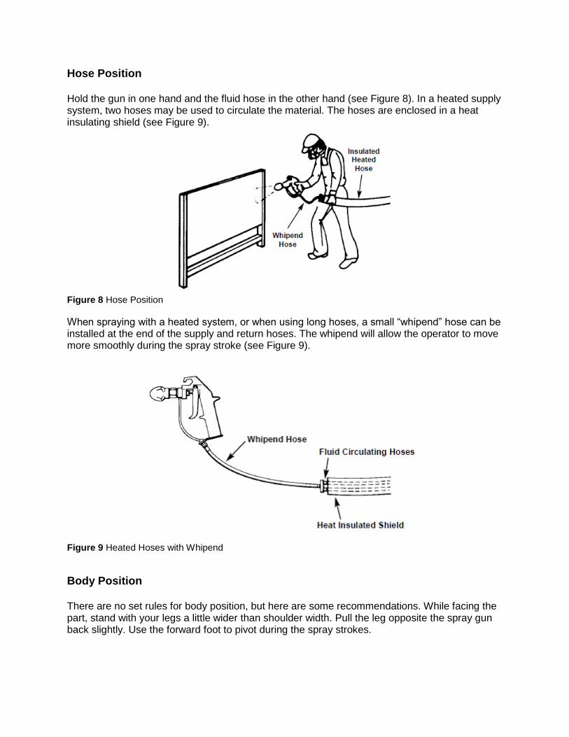
Hose Position Hold the gun in one hand and the fluid hose in the other hand (see Figure 8). In a heated supply system, two hoses may be used to circulate the material. The hoses are enclosed in a heat insulating shield (see Figure 9).
Figure 8 Hose Position
When spraying with a heated system, or when using long hoses, a small “whipend” hose can be installed at the end of the supply and return hoses. The whipend will allow the operator to move more smoothly during the spray stroke (see Figure 9).
Figure 9 Heated Hoses with Whipend
Body Position There are no set rules for body position, but here are some recommendations. While facing the part, stand with your legs a little wider than shoulder width. Pull the leg opposite the spray gun back slightly. Use the forward foot to pivot during the spray strokes.
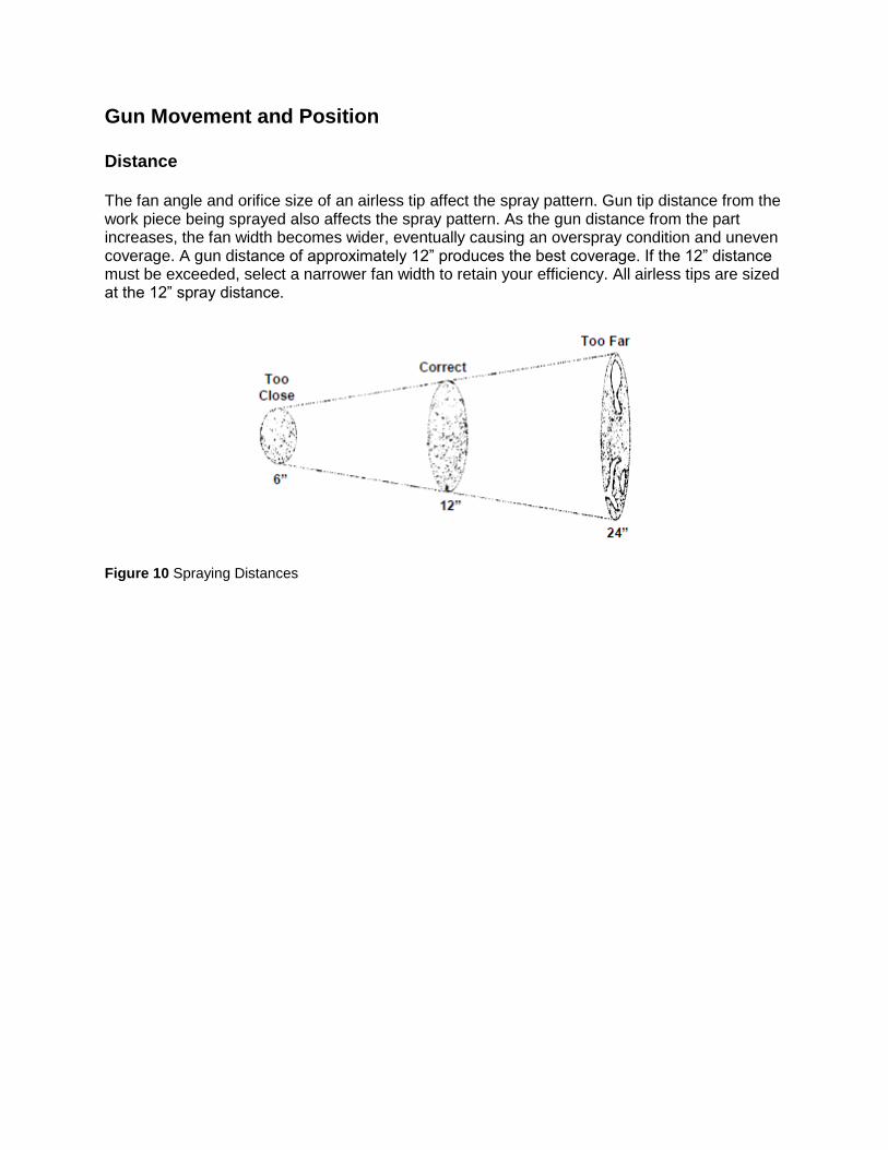
Gun Movement and Position Distance The fan angle and orifice size of an airless tip affect the spray pattern. Gun tip distance from the work piece being sprayed also affects the spray pattern. As the gun distance from the part increases, the fan width becomes wider, eventually causing an overspray condition and uneven coverage. A gun distance of approximately 12” produces the best coverage. If the 12” distance must be exceeded, select a narrower fan width to retain your efficiency. All airless tips are sized at the 12” spray distance.
Figure 10 Spraying Distances
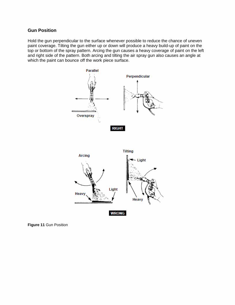
Gun Position Hold the gun perpendicular to the surface whenever possible to reduce the chance of uneven paint coverage. Tilting the gun either up or down will produce a heavy build-up of paint on the top or bottom of the spray pattern. Arcing the gun causes a heavy coverage of paint on the left and right side of the pattern. Both arcing and tilting the air spray gun also causes an angle at which the paint can bounce off the work piece surface.
Figure 11 Gun Position
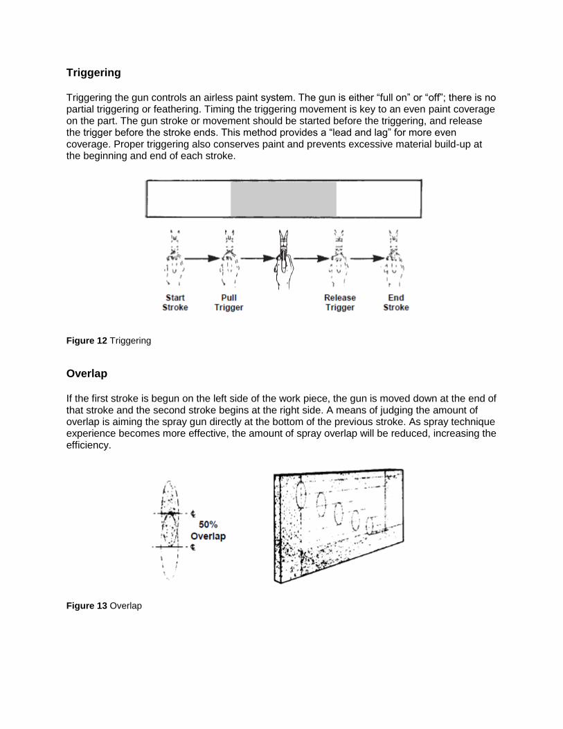
Triggering Triggering the gun controls an airless paint system. The gun is either “full on” or “off”; there is no partial triggering or feathering. Timing the triggering movement is key to an even paint coverage on the part. The gun stroke or movement should be started before the triggering, and release the trigger before the stroke ends. This method provides a “lead and lag” for more even coverage. Proper triggering also conserves paint and prevents excessive material build-up at the beginning and end of each stroke.
Figure 12 Triggering
Overlap If the first stroke is begun on the left side of the work piece, the gun is moved down at the end of that stroke and the second stroke begins at the right side. A means of judging the amount of overlap is aiming the spray gun directly at the bottom of the previous stroke. As spray technique experience becomes more effective, the amount of spray overlap will be reduced, increasing the efficiency.
Figure 13 Overlap
Spray Speed The proper spray speed applies a full wet coat application with each stroke without sagging. If the desired film thickness cannot be obtained with a single pass because of “sagging”, then two or more coats can be applied with a flash-off period between each coat. The spray movement should be at a comfortable rate. If excessive spray gun movement is necessary to avoid flooding the work, then the fluid tip orifice is too large or the fluid pressure is too high. If the stroke speed is very slow in order to apply full wet coats, then the fluid pressure should be increased slightly or a larger tip be used.
Work Piece Configurations Rehearsing your spray strokes before doing the actual work is a good practice for a new work piece and a new operator. By rehearsing the gun movement for a part, the operator can save paint with reduced overspray, have less fatigue by using more effective gun movements, and obtain a finer quality of finish. This section examines various party configurations and recommends some spraying techniques using the least effort, with minimum paint waste, yet providing the best quality of finish.
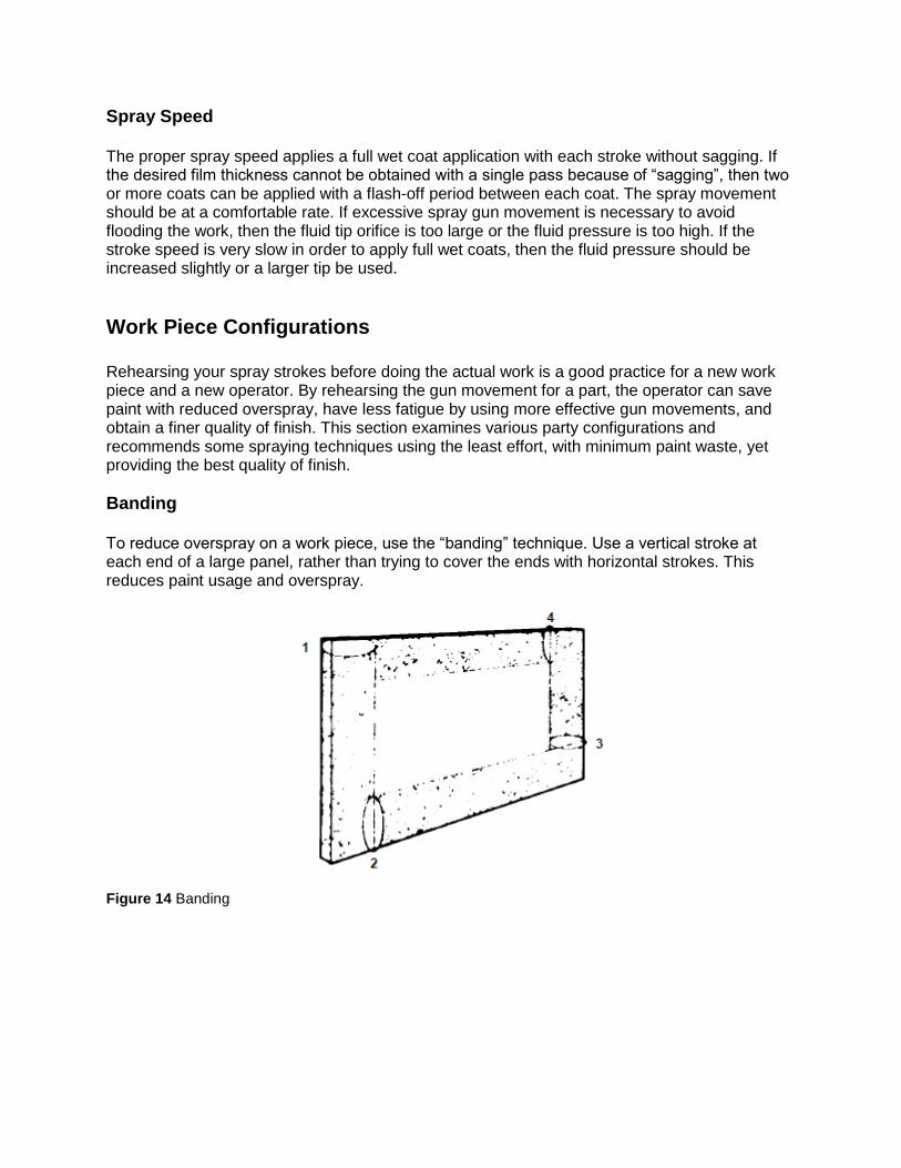
Banding To reduce overspray on a work piece, use the “banding” technique. Use a vertical stroke at each end of a large panel, rather than trying to cover the ends with horizontal strokes. This reduces paint usage and overspray.
Figure 14 Banding
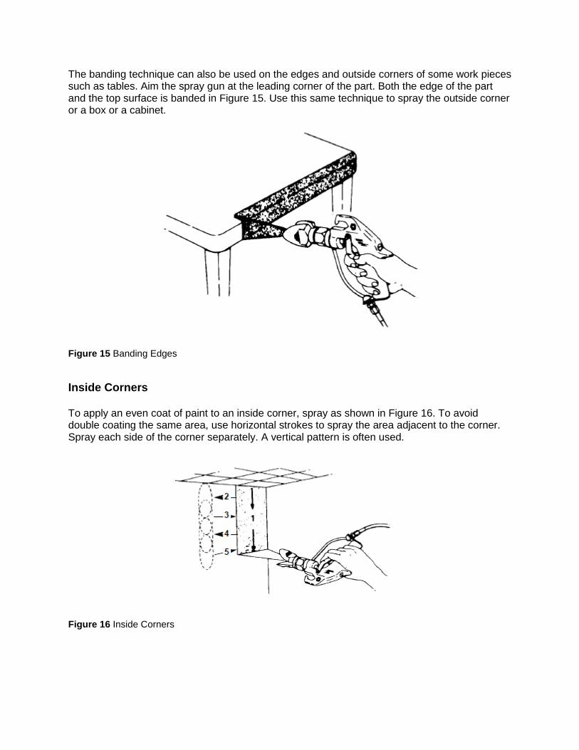
The banding technique can also be used on the edges and outside corners of some work pieces such as tables. Aim the spray gun at the leading corner of the part. Both the edge of the part and the top surface is banded in Figure 15. Use this same technique to spray the outside corner or a box or a cabinet.
Figure 15 Banding Edges
Inside Corners To apply an even coat of paint to an inside corner, spray as shown in Figure 16. To avoid double coating the same area, use horizontal strokes to spray the area adjacent to the corner. Spray each side of the corner separately. A vertical pattern is often used.
Figure 16 Inside Corners
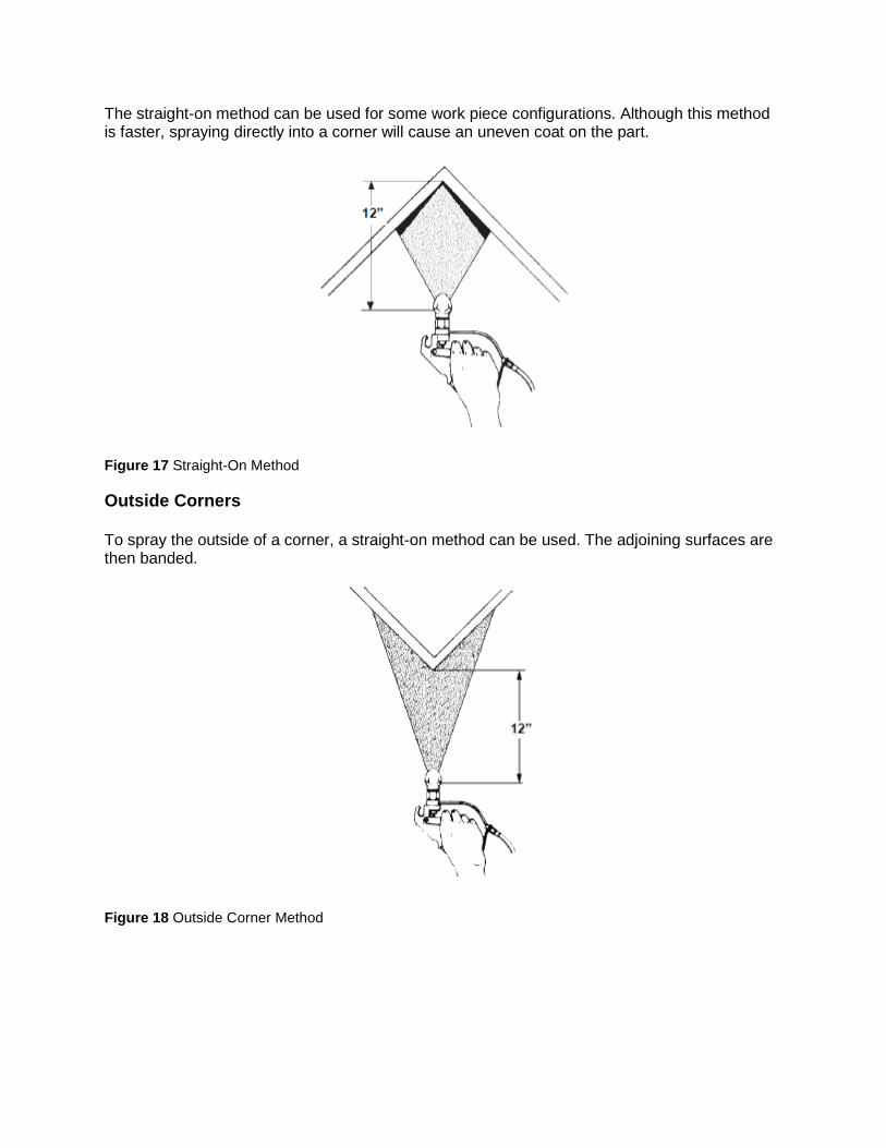
The straight-on method can be used for some work piece configurations. Although this method is faster, spraying directly into a corner will cause an uneven coat on the part.
Figure 17 Straight-On Method
Outside Corners To spray the outside of a corner, a straight-on method can be used. The adjoining surfaces are then banded.
Figure 18 Outside Corner Method
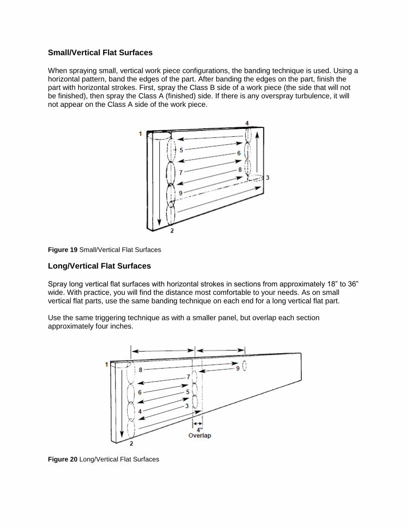
Small/Vertical Flat Surfaces When spraying small, vertical work piece configurations, the banding technique is used. Using a horizontal pattern, band the edges of the part. After banding the edges on the part, finish the part with horizontal strokes. First, spray the Class B side of a work piece (the side that will not be finished), then spray the Class A (finished) side. If there is any overspray turbulence, it will not appear on the Class A side of the work piece.
Figure 19 Small/Vertical Flat Surfaces
Long/Vertical Flat Surfaces Spray long vertical flat surfaces with horizontal strokes in sections from approximately 18” to 36” wide. With practice, you will find the distance most comfortable to your needs. As on small vertical flat parts, use the same banding technique on each end for a long vertical flat part. Use the same triggering technique as with a smaller panel, but overlap each section approximately four inches.
Figure 20 Long/Vertical Flat Surfaces
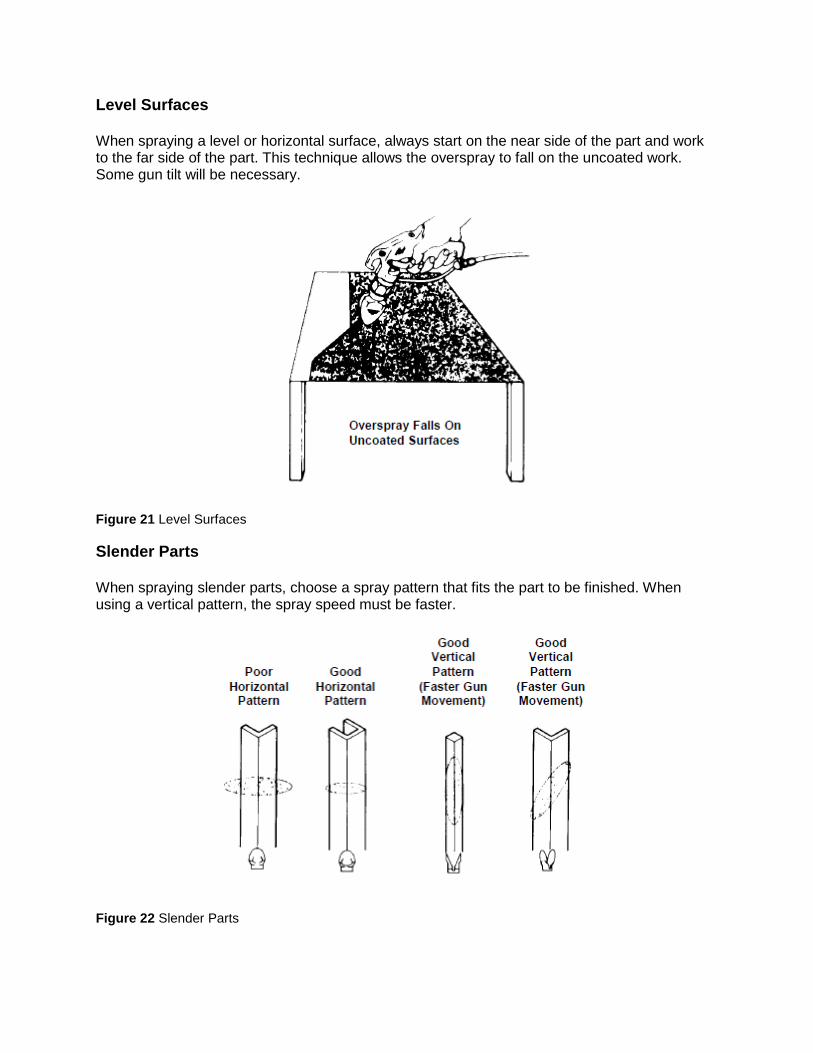
Level Surfaces When spraying a level or horizontal surface, always start on the near side of the part and work to the far side of the part. This technique allows the overspray to fall on the uncoated work. Some gun tilt will be necessary.
Figure 21 Level Surfaces
Slender Parts When spraying slender parts, choose a spray pattern that fits the part to be finished. When using a vertical pattern, the spray speed must be faster.
Figure 22 Slender Parts
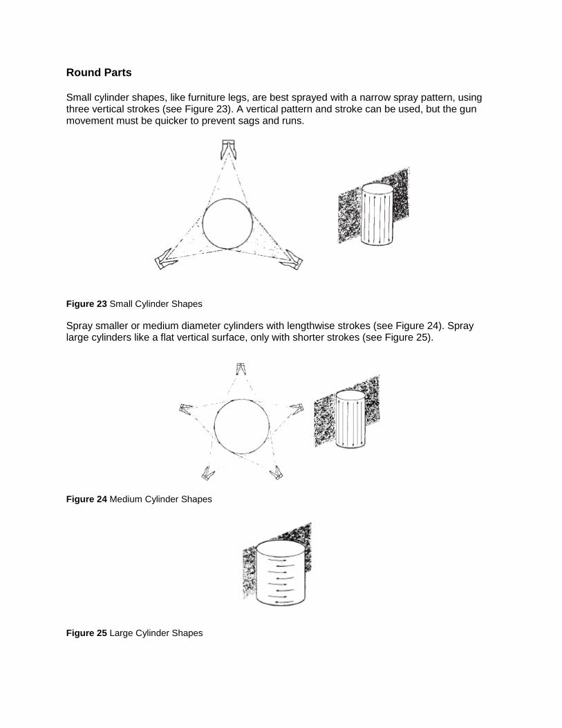
Round Parts Small cylinder shapes, like furniture legs, are best sprayed with a narrow spray pattern, using three vertical strokes (see Figure 23). A vertical pattern and stroke can be used, but the gun movement must be quicker to prevent sags and runs.
Figure 23 Small Cylinder Shapes
Spray smaller or medium diameter cylinders with lengthwise strokes (see Figure 24). Spray large cylinders like a flat vertical surface, only with shorter strokes (see Figure 25).
Figure 24 Medium Cylinder Shapes
Figure 25 Large Cylinder Shapes
IV. OPERATOR MAINTENANCE Regular Maintenance
1. Clean out the front of the tip at least twice a day with a solvent-soaked brush to keep material from building up and clogging the tip.
2. Check the fluid filters periodically. Clean or replace filters as needed.
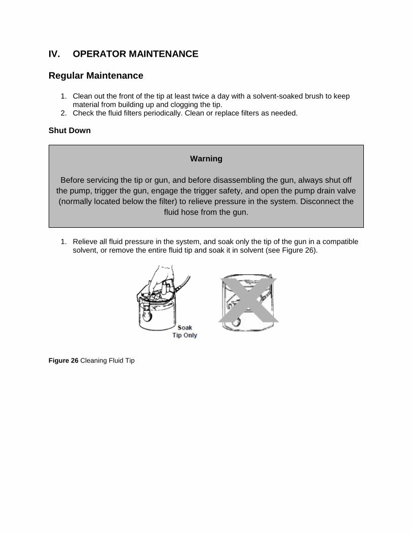
Shut Down
1. Relieve all fluid pressure in the system, and soak only the tip of the gun in a compatible solvent, or remove the entire fluid tip and soak it in solvent (see Figure 26).
Figure 26 Cleaning Fluid Tip
Warning
Before servicing the tip or gun, and before disassembling the gun, always shut off
the pump, trigger the gun, engage the trigger safety, and open the pump drain valve
(normally located below the filter) to relieve pressure in the system. Disconnect the
fluid hose from the gun.
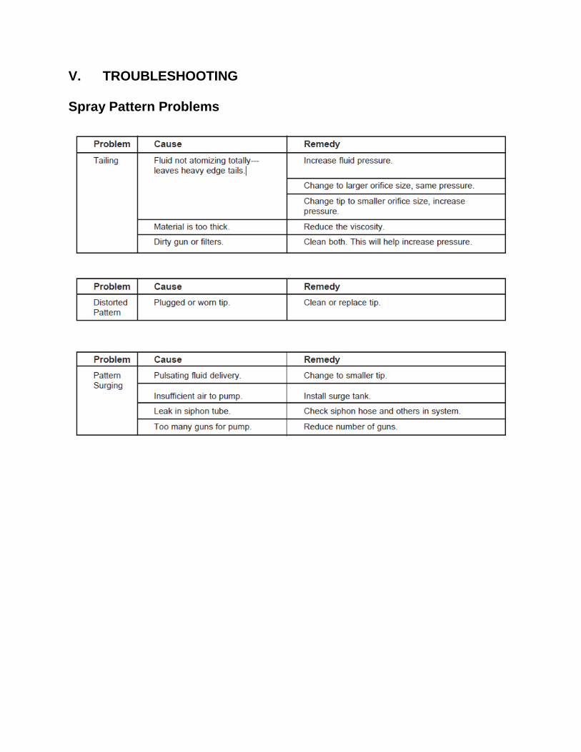
V. TROUBLESHOOTING Spray Pattern Problems