Embed Size (px)
Citation preview

Airframe
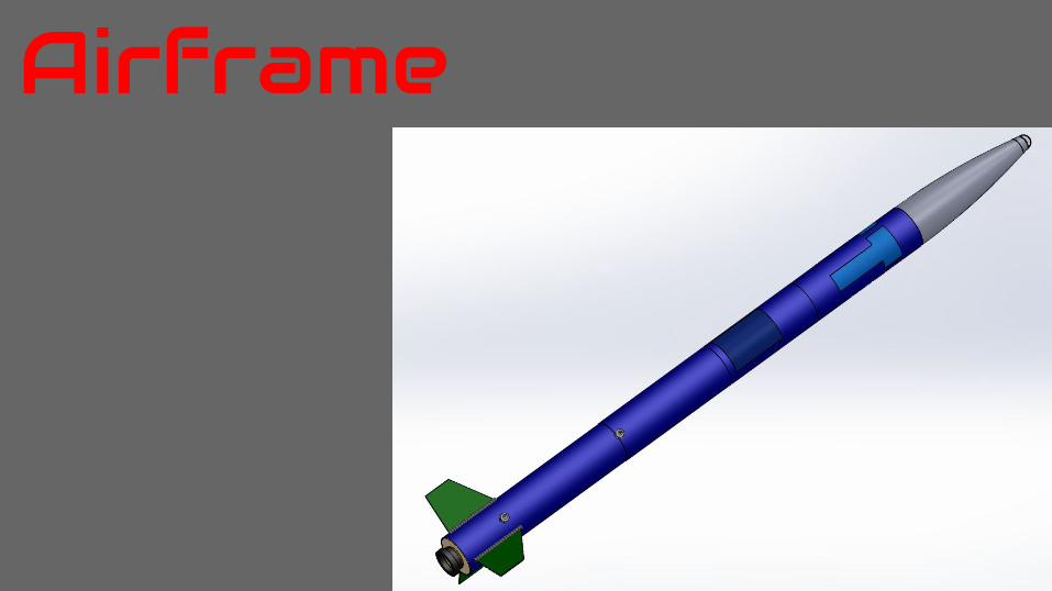
Vehicle Summary● Overall length: 8’ 7”● Total Weight: 32.06 lbs
○ Expected Weight Range: 30-34 lbs
● Diameter: 6”● Nose cone length (ogive): 24”● Payload section length: 18”● Avionics section length: 15”● Recovery section length: 18”● Booster section length: 2’ 3”
Airframe● Motor type: Aerotech L1150 motor● CG: 59.85” from nose cone tip● CP: 76.56” from nose cone tip● Stability margin: 2.78 calibers● Thrust to weight ratio: 8.064● Launch rod size: 12’ 1515 rail● Rail exit velocity: 78.7 ft/s
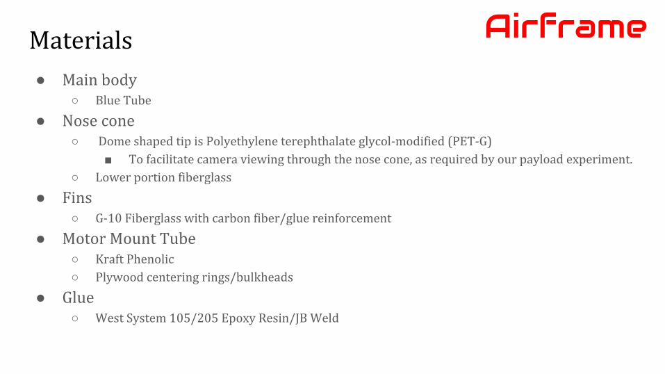
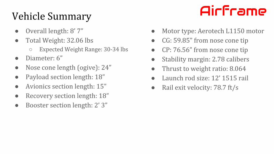
Materials
● Main body○ Blue Tube
● Nose cone○ Dome shaped tip is Polyethylene terephthalate glycol-modified (PET-G)
■ To facilitate camera viewing through the nose cone, as required by our payload experiment.
○ Lower portion fiberglass
● Fins○ G-10 Fiberglass with carbon fiber/glue reinforcement
● Motor Mount Tube○ Kraft Phenolic
○ Plywood centering rings/bulkheads
● Glue○ West System 105/205 Epoxy Resin/JB Weld
Airframe

Booster SectionAirframe
1. G-10 Fiberglass Fins2. Kraft Phenolic Motor Mount3. Plywood Centering Rings4. 75mm Motor Retainer5. Carbon Fiber Fillets6. Plywood Bulkhead7. 1515 Rail Buttons
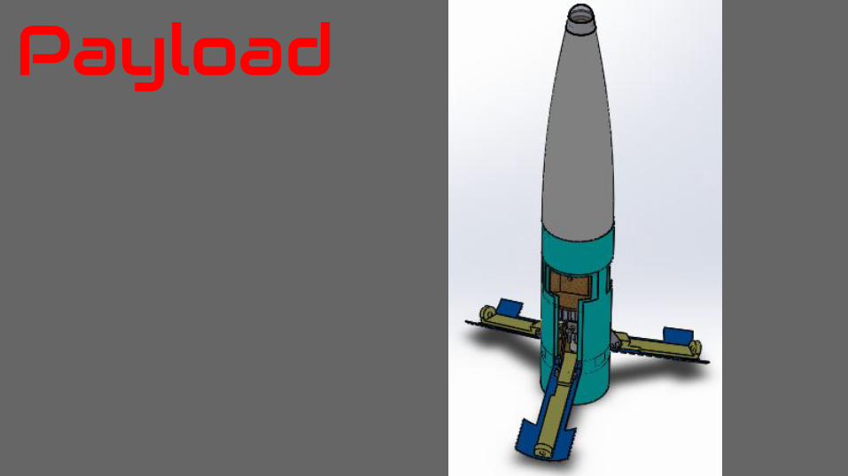
Payload
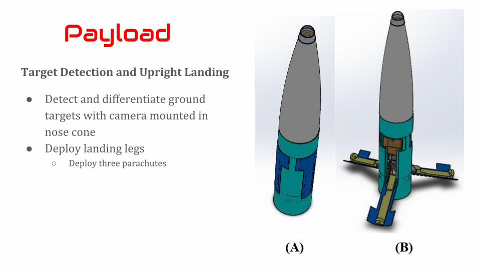
Target Detection and Upright Landing
● Detect and differentiate ground targets with camera mounted in nose cone
● Deploy landing legs○ Deploy three parachutes
Payload
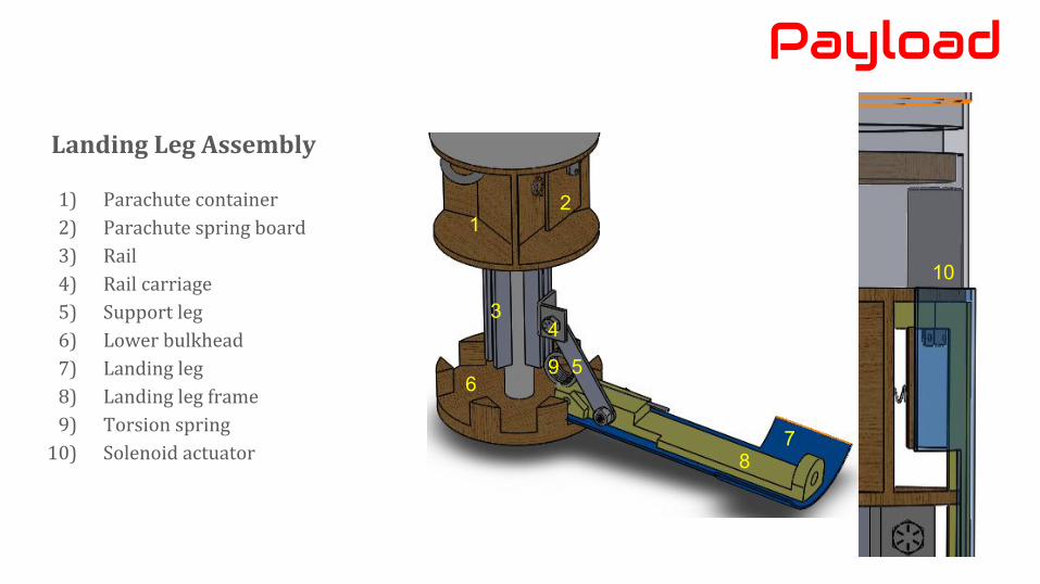
Landing Leg Assembly
1) Parachute container
2) Parachute spring board
3) Rail
4) Rail carriage
5) Support leg
6) Lower bulkhead
7) Landing leg
8) Landing leg frame
9) Torsion spring
10) Solenoid actuator
Payload
1
3
56
78
9
2
10
4
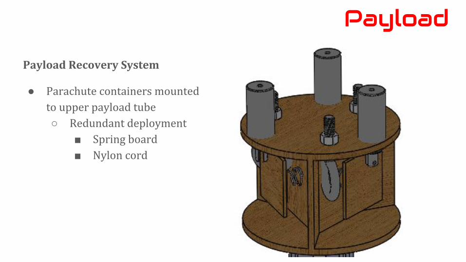
Payload Recovery System
● Parachute containers mounted to upper payload tube○ Redundant deployment
■ Spring board■ Nylon cord
Payload

Target Detection Procedure:
The algorithm will follow these steps for each image taken:
● Search the image captured for the three targets (regions of color in the image) by sampling pixels at regular intervals.
● If any targets are found, save the image to the file system, along with a timestamp and the positions of the detected targets. If no targets are found, don't save anything to the file system.
Some exceptions do apply - under conditions that would cause undue glare, such as the camera being pointed at the sun (see top left image), the algorithm will skip so as not to generate a false positive.
Payload
The camera experienced glare often,
Photos from subscale launch:
But was still able to pick out small features on the ground

PHASE EVENT
1 Ignition.
2 Powered flight.
3 Coasting.
4 Drogue parachute deployed at apogee(projected at 5,322 ft. AGL)
5 Main parachute deployed at an altitude of 1,000 ft. AGL.
6 Camera in the nosecone of the rocket begins target spotting.
7 Payload section deploys itself from rocket and deploys its legs and three parachutes.
8 All sections of the rocket land with a KE under 75 ft-lbf.
Payload/Recovery
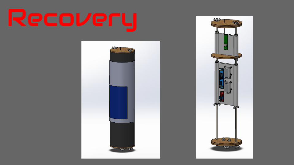
Recovery

Avionics BayExternal Design- removable door- covered by an O-ring
Internal Design- 3D printed sled- two rod system
Recovery
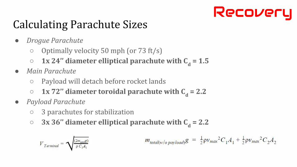
Calculating Parachute Sizes● Drogue Parachute
○ Optimally velocity 50 mph (or 73 ft/s)○ 1x 24’’ diameter elliptical parachute with C
d = 1.5
● Main Parachute○ Payload will detach before rocket lands○ 1x 72’’ diameter toroidal parachute with C
d = 2.2
● Payload Parachute○ 3 parachutes for stabilization○ 3x 36’’ diameter elliptical parachute with C
d = 2.2
Recovery

Tender Descender SystemRecovery
● Connected in series
● ¼” tubular kevlar
● Detachable wires
● Quicklinks
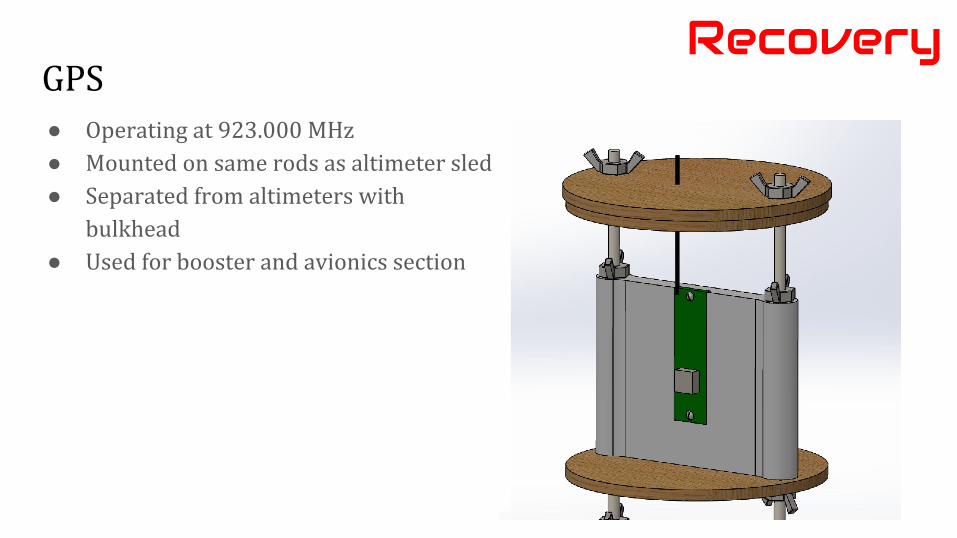
GPSRecovery
● Operating at 923.000 MHz● Mounted on same rods as altimeter sled● Separated from altimeters with
bulkhead● Used for booster and avionics section
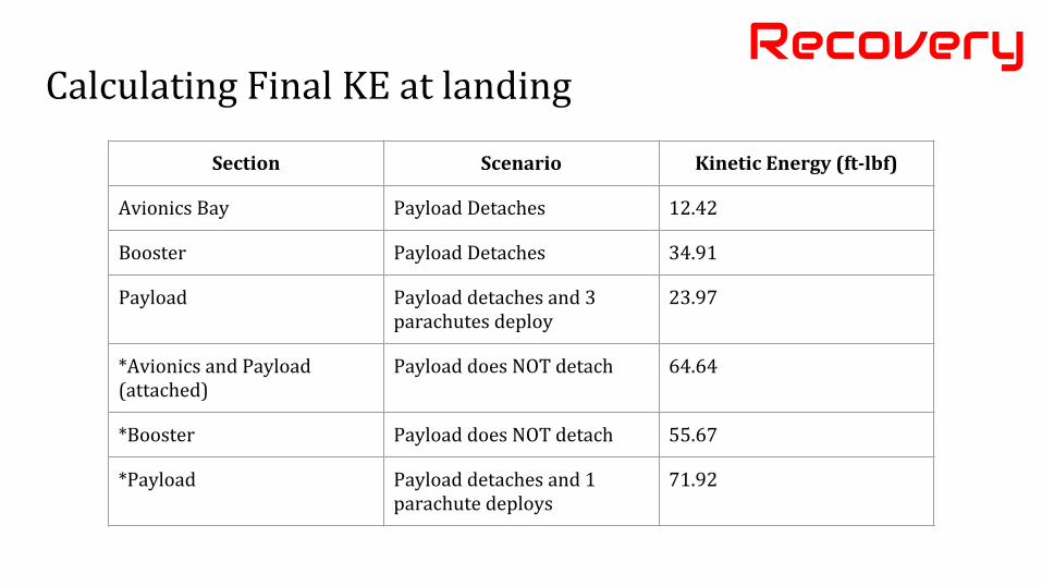
Calculating Final KE at landingRecovery
Section Scenario Kinetic Energy (ft-lbf)
Avionics Bay Payload Detaches 12.42
Booster Payload Detaches 34.91
Payload Payload detaches and 3 parachutes deploy
23.97
*Avionics and Payload (attached)
Payload does NOT detach 64.64
*Booster Payload does NOT detach 55.67
*Payload Payload detaches and 1 parachute deploys
71.92
Vehicle Interfaces
Vehicle Interfaces
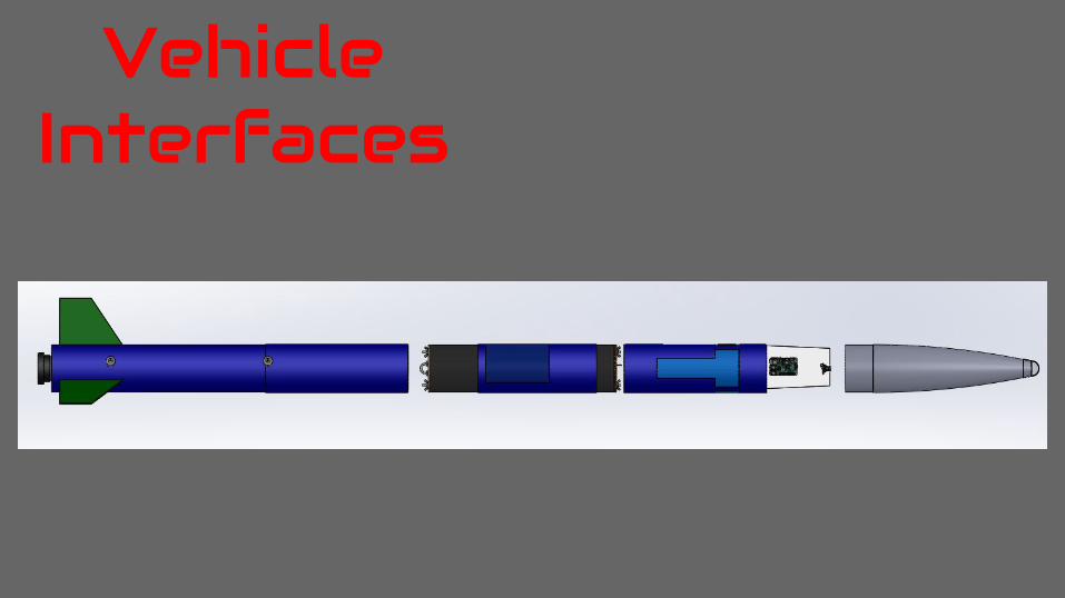
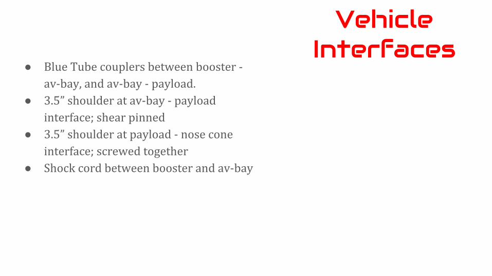
● Blue Tube couplers between booster - av-bay, and av-bay - payload.
● 3.5” shoulder at av-bay - payload interface; shear pinned
● 3.5” shoulder at payload - nose cone interface; screwed together
● Shock cord between booster and av-bay
Flight Simulations
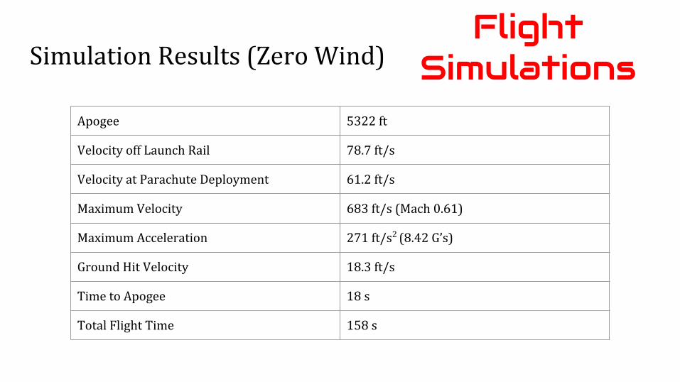
Simulation Results (Zero Wind)
Apogee 5322 ft
Velocity off Launch Rail 78.7 ft/s
Velocity at Parachute Deployment 61.2 ft/s
Maximum Velocity 683 ft/s (Mach 0.61)
Maximum Acceleration 271 ft/s2 (8.42 G’s)
Ground Hit Velocity 18.3 ft/s
Time to Apogee 18 s
Total Flight Time 158 s
Flight Simulations

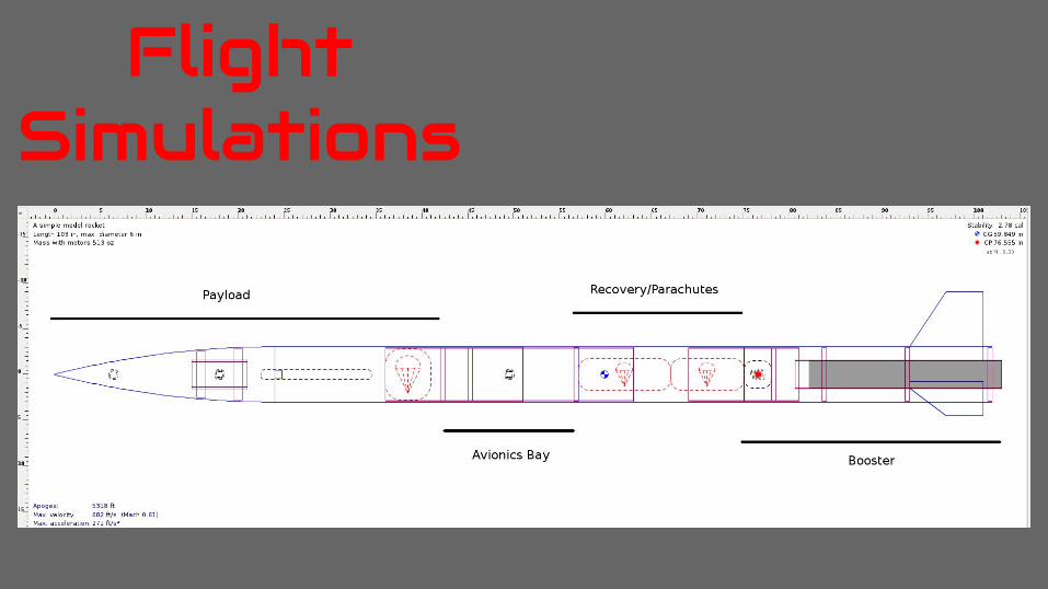
Simulated Flight ProfileFlight
Simulations
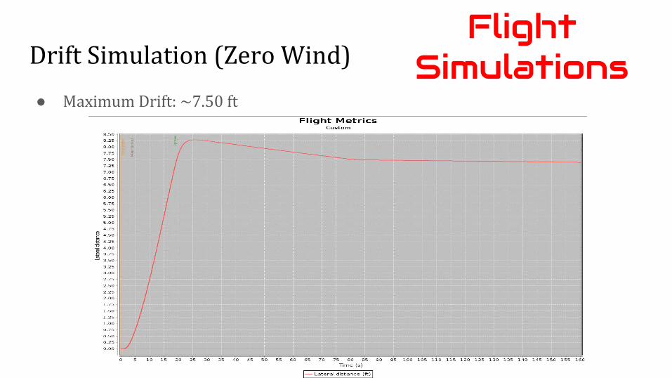
Drift Simulation (Zero Wind)
● Maximum Drift: ~7.50 ft
Flight Simulations
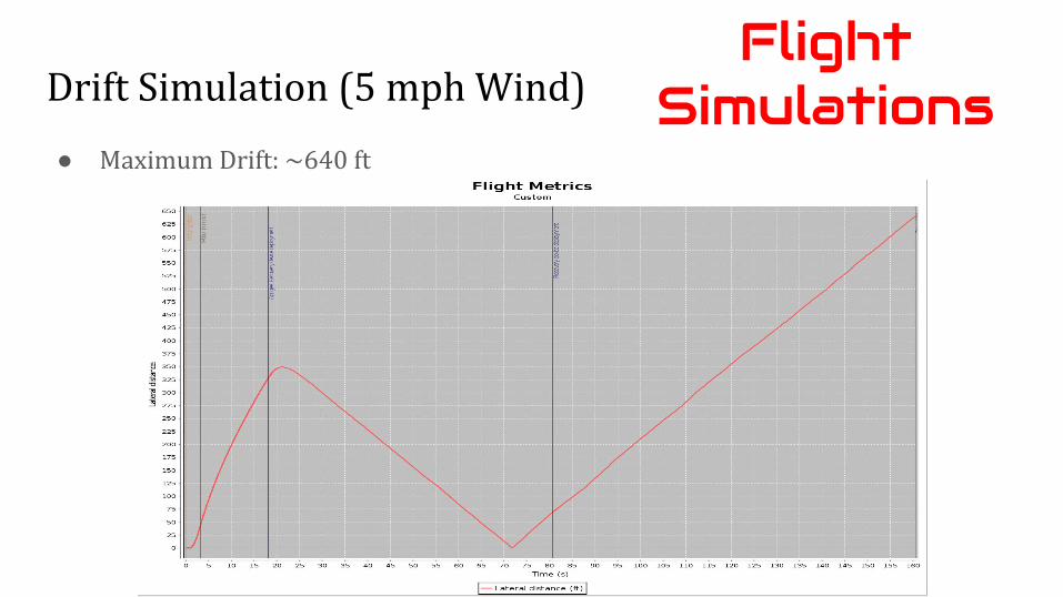
Drift Simulation (5 mph Wind)
● Maximum Drift: ~640 ft
Flight Simulations

Drift Simulation (10 mph Wind)
● Maximum Drift: ~1330 ft
Flight Simulations
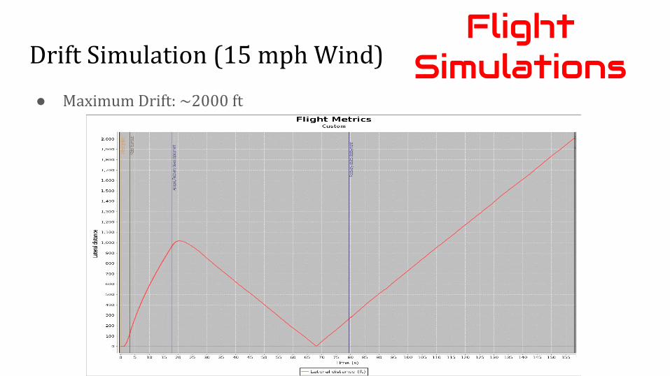
Drift Simulation (15 mph Wind)
● Maximum Drift: ~2000 ft
Flight Simulations
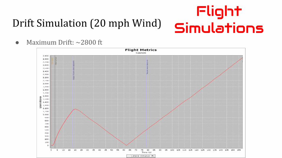
Drift Simulation (20 mph Wind)
● Maximum Drift: ~2800 ft
Flight Simulations
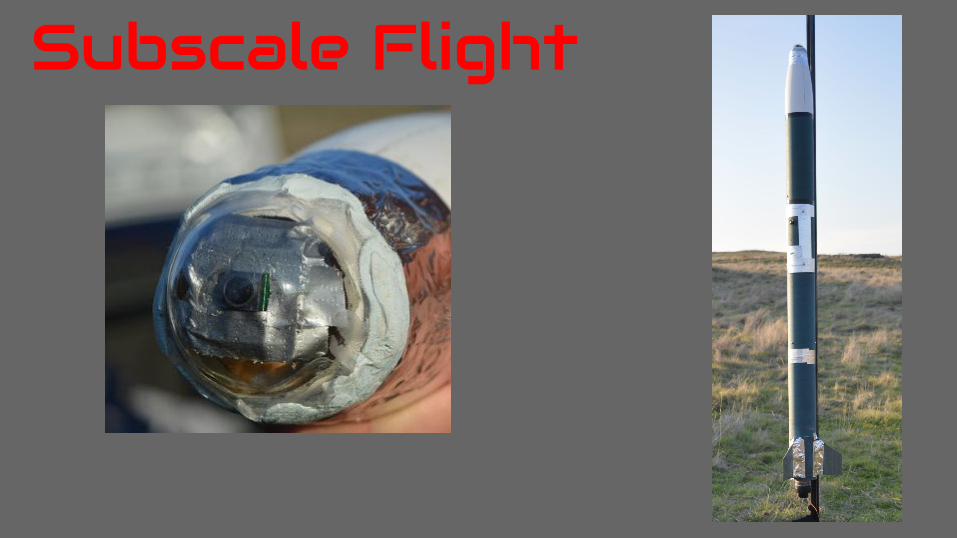
Subscale Flight

Vehicle Summary
● Scaling: ⅔ length and diameter● Length: 5’ 5”● Weight: 11.614 lbs● Diameter: 4”● Motor: Aerotech J800
Subscale Flight
● CG: 37.845” from nose cone tip● CP: 47.326” from nose cone tip● Stability margin: 2.37 calibers
● Recovery system tested● Camera hardware tested● Payload simulated with ballast
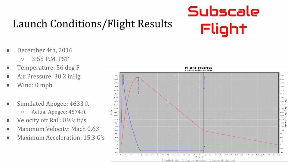
Launch Conditions/Flight Results
● Simulated Apogee: 4633 ft○ Actual Apogee: 4574 ft
● Velocity off Rail: 89.9 ft/s● Maximum Velocity: Mach 0.63● Maximum Acceleration: 15.3 G’s
● December 4th, 2016○ 3:55 P.M. PST
● Temperature: 56 deg F● Air Pressure: 30.2 inHg● Wind: 0 mph
Subscale Flight
Impact on Final Design
● Nose cone tip design/manufacture○ Better 3D mold○ Different epoxy○ Scratch resistant cover/spray○ Reduce transparent area to decrease glare
● Motor Mount Construction○ Step-by-step process ensures alignment of fins○ Ensures all steps are carried out○ Nothing is missed
Subscale Flight

Safety

General
Safety Officer: Grant Posner
Mentor: David Raimondi● President of Livermore Unit of NAR (LUNAR)
○ Advises team○ Owns project○ Handles motor hardware
Safety

Personnel Hazards: Greatest Risks
● Construction injuries
● Launch safety: energetic devices○ Subscale tests○ Full-scale tests/launches
Safety

Environmental Risk
1. Minimize any environmental issues during the design phase.2. Be aware of applicable laws and regulations.3. Identify and rate all risks.4. Have containment and remediation plans.
Safety

Project Plan/
Outreach
Test Plans and Procedures
● Payload Tests○ Camera/Target Identification
■ Received data from subscale flight○ Drop Test/Upright Landing○ Parachute Deployment Test
● Epoxy Strength Test● Testing variables will ensure durability of design
Project Plan
Status of Requirement Verification
● All design requirements fulfilled○ Subscale vehicle and recovery test completed○ Full-scale vehicle, payload, and recovery test scheduled
for Feb. 4th, 2017 (alt. Launch on Feb. 18th)● Redundant verification when possible
Project Plan

Outreach Plan
● Habitat for Humanity STEM Outreach Day● KIPP Public Charter School
○ In contact with 7th grade teacher and program coordinator
● Currently signing up for more outreach programs○ Expanding Your Horizons, UC Berkeley Engineers Week,
etc.
Project Plan

Questions?

Thank You