Embed Size (px)
Citation preview

1. Airframe2. Payload3. Recovery4. Vehicle Interfaces5. Flight Simulations6. Full-Scale Flight7. Project Plan8. Full-Scale Reflight
Presentation Map
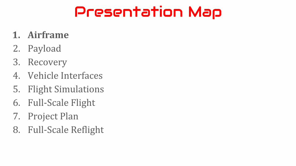
Airframe
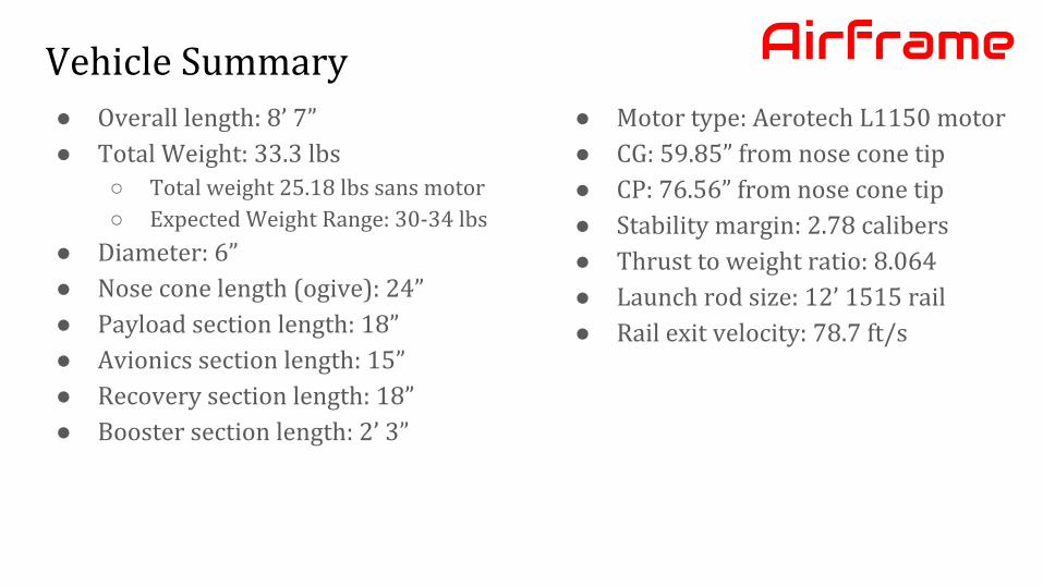
Vehicle Summary● Overall length: 8’ 7”● Total Weight: 33.3 lbs
○ Total weight 25.18 lbs sans motor○ Expected Weight Range: 30-34 lbs
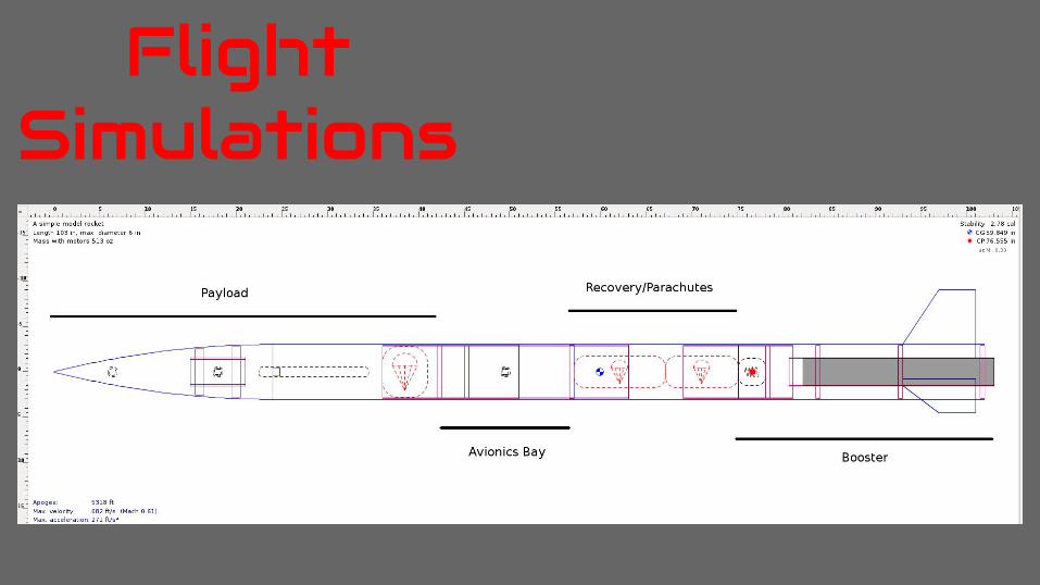
● Diameter: 6”● Nose cone length (ogive): 24”● Payload section length: 18”● Avionics section length: 15”● Recovery section length: 18”● Booster section length: 2’ 3”
Airframe● Motor type: Aerotech L1150 motor● CG: 59.85” from nose cone tip● CP: 76.56” from nose cone tip● Stability margin: 2.78 calibers● Thrust to weight ratio: 8.064● Launch rod size: 12’ 1515 rail● Rail exit velocity: 78.7 ft/s
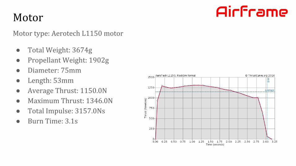
MotorMotor type: Aerotech L1150 motor
● Total Weight: 3674g● Propellant Weight: 1902g● Diameter: 75mm● Length: 53mm● Average Thrust: 1150.0N● Maximum Thrust: 1346.0N● Total Impulse: 3157.0Ns● Burn Time: 3.1s
Airframe
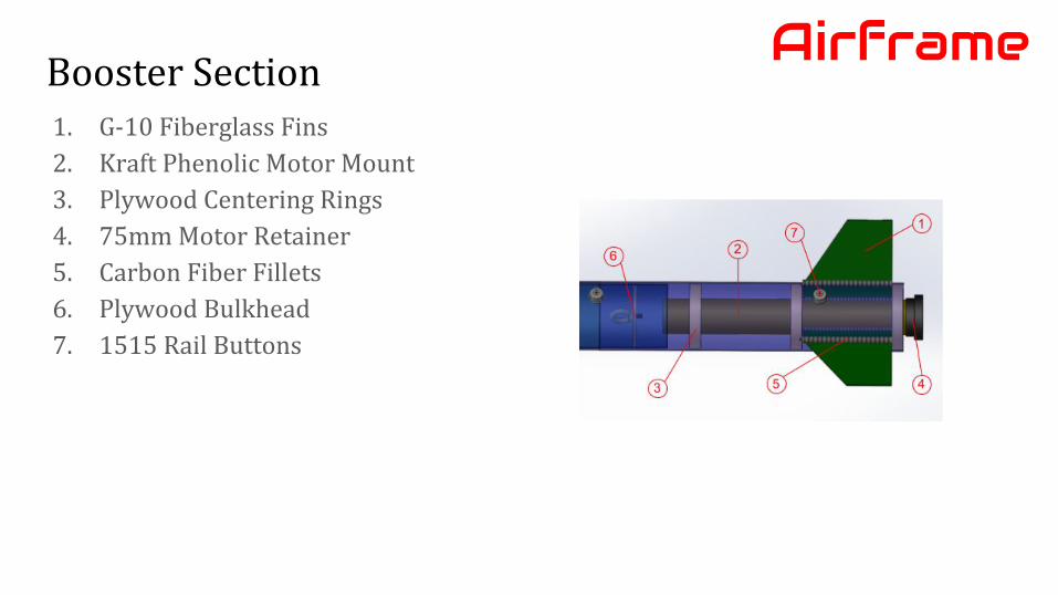
Booster SectionAirframe
1. G-10 Fiberglass Fins2. Kraft Phenolic Motor Mount3. Plywood Centering Rings4. 75mm Motor Retainer5. Carbon Fiber Fillets6. Plywood Bulkhead7. 1515 Rail Buttons
1. Airframe2. Payload3. Recovery4. Vehicle Interfaces5. Flight Simulations6. Full-Scale Flight7. Project Plan8. Full-Scale Reflight
Presentation Map
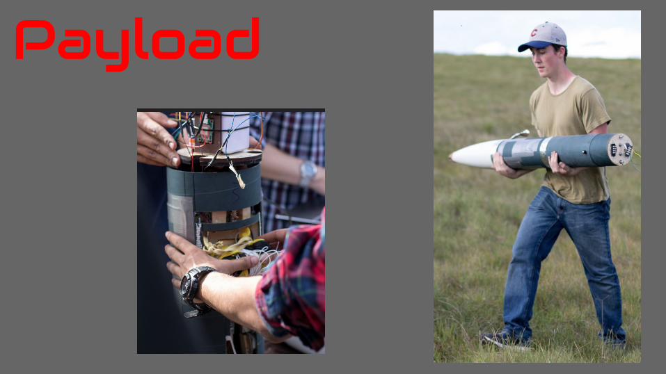
Payload
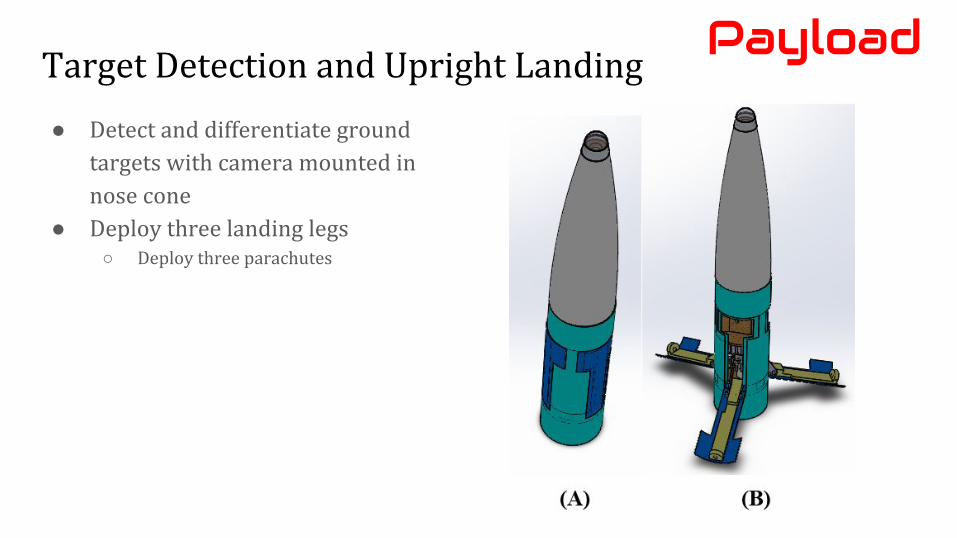
Target Detection and Upright Landing
● Detect and differentiate ground targets with camera mounted in nose cone
● Deploy three landing legs○ Deploy three parachutes
Payload
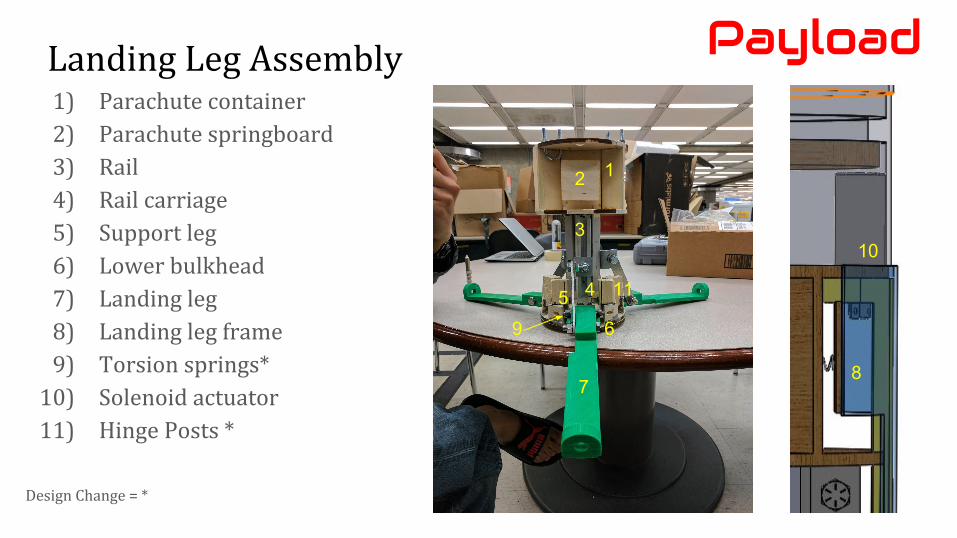
1) Parachute container2) Parachute springboard3) Rail4) Rail carriage5) Support leg6) Lower bulkhead7) Landing leg8) Landing leg frame9) Torsion springs*
10) Solenoid actuator11) Hinge Posts *
Payload
1
3
56
78
9
2
10
4
Landing Leg Assembly
Design Change = *
11
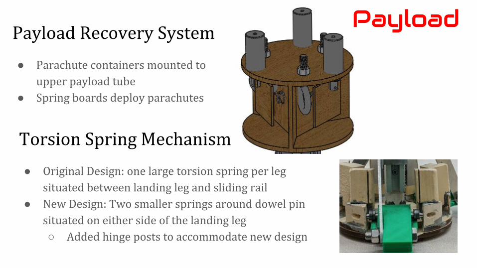
Payload Recovery System
● Parachute containers mounted to upper payload tube
● Spring boards deploy parachutes
Payload
Torsion Spring Mechanism
● Original Design: one large torsion spring per leg situated between landing leg and sliding rail
● New Design: Two smaller springs around dowel pin situated on either side of the landing leg○ Added hinge posts to accommodate new design
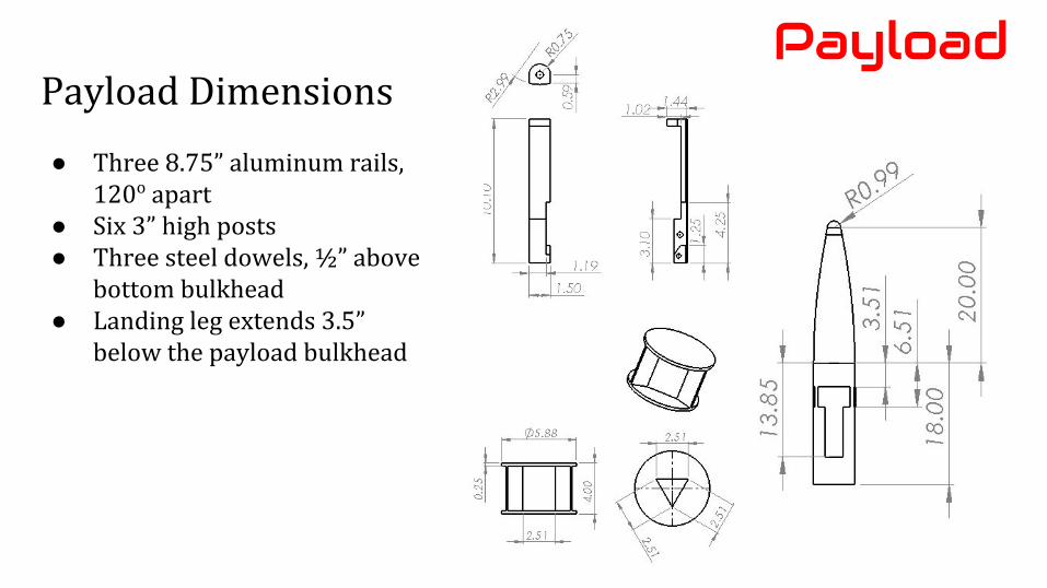
Payload Dimensions
● Three 8.75” aluminum rails, 120o apart
● Six 3” high posts● Three steel dowels, ½” above
bottom bulkhead● Landing leg extends 3.5”
below the payload bulkhead
Payload
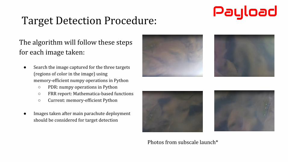
The algorithm will follow these steps for each image taken:
● Search the image captured for the three targets (regions of color in the image) using memory-efficient numpy operations in Python
○ PDR: numpy operations in Python○ FRR report: Mathematica-based functions○ Current: memory-efficient Python
● Images taken after main parachute deployment should be considered for target detection
Photos from subscale launch*
PayloadTarget Detection Procedure:
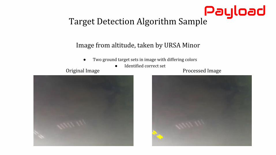
Target Detection Algorithm Sample
Image from altitude, taken by URSA Minor
● Two ground target sets in image with differing colors● Identified correct set
Payload
Processed ImageOriginal Image
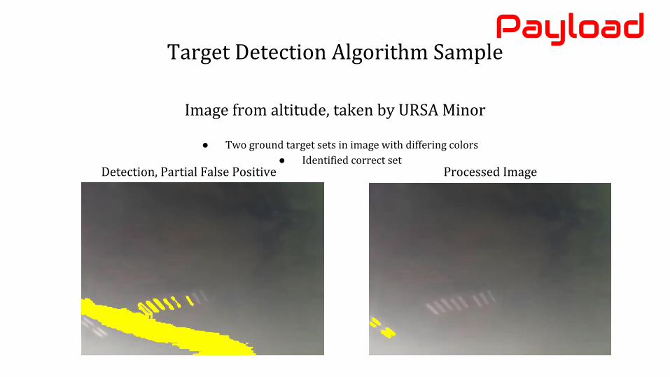
Target Detection Algorithm Sample
Image from altitude, taken by URSA Minor
● Two ground target sets in image with differing colors● Identified correct set
Payload
Processed ImageDetection, Partial False Positive
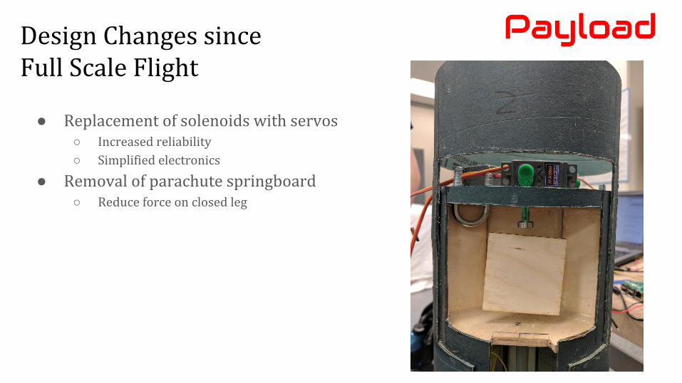
Design Changes since Full Scale Flight
● Replacement of solenoids with servos○ Increased reliability
○ Simplified electronics
● Removal of parachute springboard○ Reduce force on closed leg
Payload
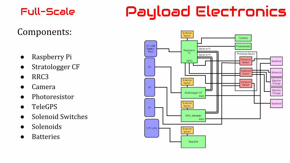
Components:
● Raspberry Pi● Stratologger CF● RRC3● Camera● Photoresistor● TeleGPS● Solenoid Switches● Solenoids● Batteries
Payload ElectronicsFull-Scale
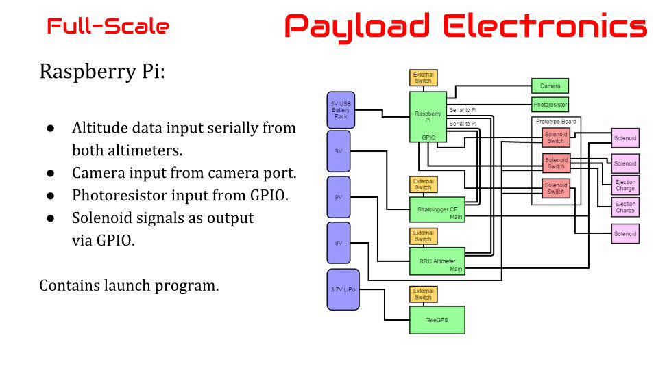
Raspberry Pi:
● Altitude data input serially fromboth altimeters.
● Camera input from camera port.● Photoresistor input from GPIO.● Solenoid signals as output
via GPIO.
Contains launch program.
Payload ElectronicsFull-Scale
Payload ElectronicsFull-Scale
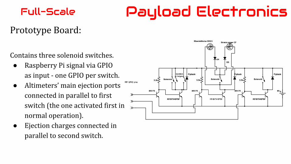
Prototype Board:
Contains three solenoid switches.● Raspberry Pi signal via GPIO
as input - one GPIO per switch.● Altimeters’ main ejection ports
connected in parallel to firstswitch (the one activated first innormal operation).
● Ejection charges connected inparallel to second switch.
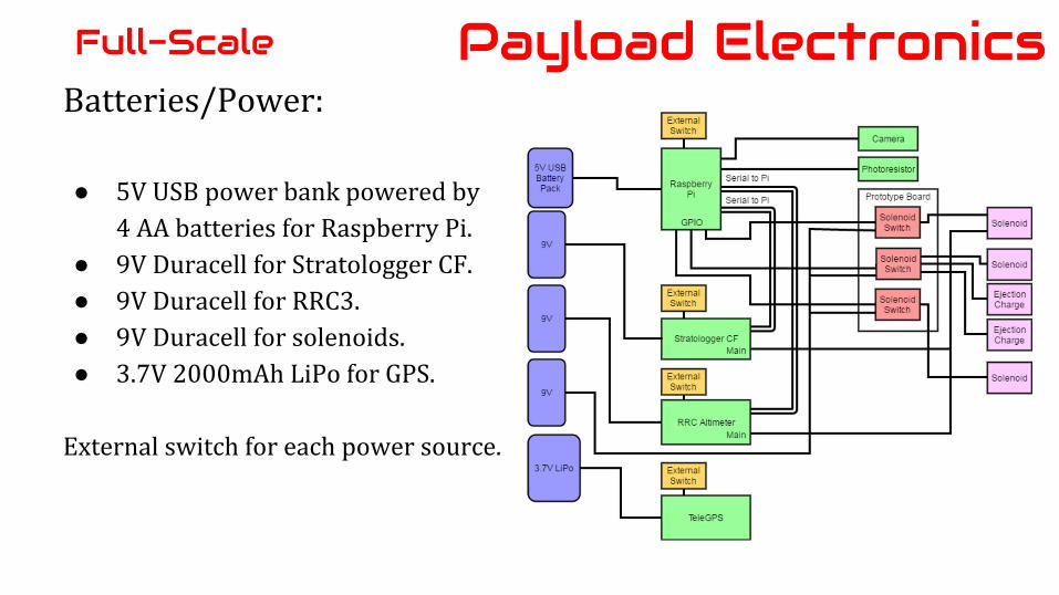
Batteries/Power:
● 5V USB power bank powered by4 AA batteries for Raspberry Pi.
● 9V Duracell for Stratologger CF.● 9V Duracell for RRC3.● 9V Duracell for solenoids.● 3.7V 2000mAh LiPo for GPS.
External switch for each power source.
Payload ElectronicsFull-Scale
Raspberry Pi:● Altitude data input serially from
both altimeters.● Camera input from camera port.● Photoresistor input from GPIO.● Servo signals as output via GPIO.● Ejection charge signal as output
via GPIO.
Contains launch program.
Payload ElectronicsFull-Scale Reflightand Competition
Launch Program
No targets to detect, so use altitude instead.
● Confirm ascent at 200’ on the way up.● Detect deployment at 700’ on the way down.● Deploy first leg.● For 15 seconds: check for light in the parachute box for the first leg.● If no light: abort remaining deployment and ejection.● If light: deploy second leg and eject payload section, then wait and deploy third
leg.
Payload ElectronicsFull-Scale
Components:● Raspberry Pi● Stratologger CF● RRC3● Camera● Photoresistor● TeleGPS● Ejection Charge Switch● Servos
● Batteries
Payload ElectronicsFull-Scale Reflightand Competition
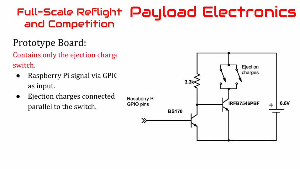
Prototype Board:Contains only the ejection charge switch.● Raspberry Pi signal via GPIO
as input.● Ejection charges connected in
parallel to the switch.
Payload ElectronicsFull-Scale Reflightand Competition
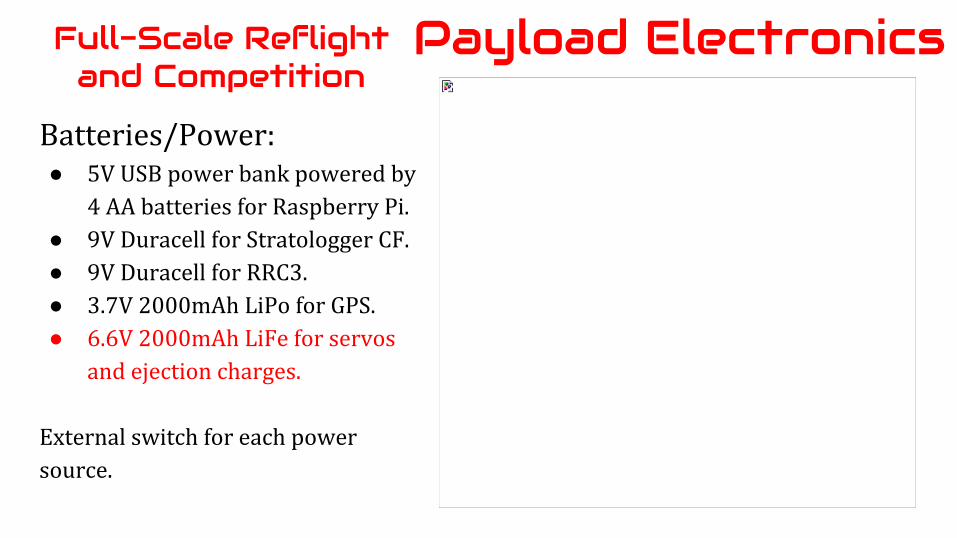
Batteries/Power:● 5V USB power bank powered by
4 AA batteries for Raspberry Pi.● 9V Duracell for Stratologger CF.● 9V Duracell for RRC3.● 3.7V 2000mAh LiPo for GPS.● 6.6V 2000mAh LiFe for servos
and ejection charges.
External switch for each power source.
Payload ElectronicsFull-Scale Reflightand Competition
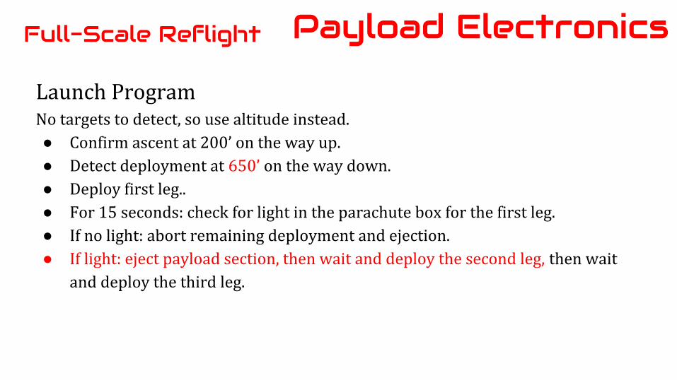
Launch ProgramNo targets to detect, so use altitude instead.● Confirm ascent at 200’ on the way up.● Detect deployment at 650’ on the way down.● Deploy first leg..● For 15 seconds: check for light in the parachute box for the first leg.● If no light: abort remaining deployment and ejection.● If light: eject payload section, then wait and deploy the second leg, then wait
and deploy the third leg.
Payload ElectronicsFull-Scale Reflight
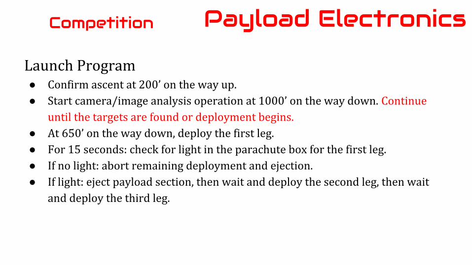
Launch Program● Confirm ascent at 200’ on the way up.● Start camera/image analysis operation at 1000’ on the way down. Continue
until the targets are found or deployment begins.● At 650’ on the way down, deploy the first leg.● For 15 seconds: check for light in the parachute box for the first leg.● If no light: abort remaining deployment and ejection.● If light: eject payload section, then wait and deploy the second leg, then wait
and deploy the third leg.
Payload ElectronicsCompetition
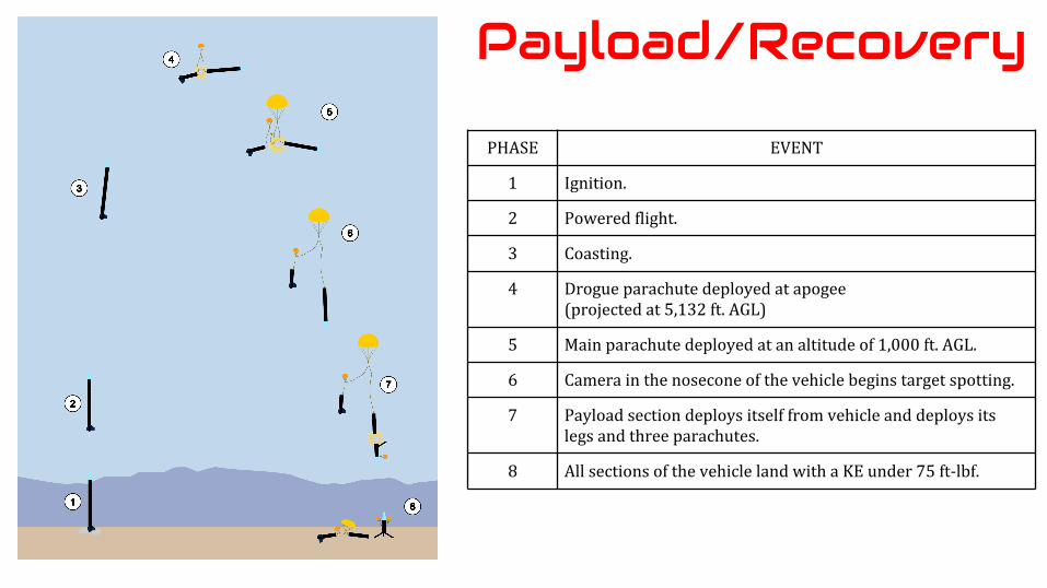
PHASE EVENT
1 Ignition.
2 Powered flight.
3 Coasting.
4 Drogue parachute deployed at apogee(projected at 5,132 ft. AGL)
5 Main parachute deployed at an altitude of 1,000 ft. AGL.
6 Camera in the nosecone of the vehicle begins target spotting.
7 Payload section deploys itself from vehicle and deploys its legs and three parachutes.
8 All sections of the vehicle land with a KE under 75 ft-lbf.
Payload/Recovery
1. Airframe2. Payload3. Recovery4. Vehicle Interfaces5. Flight Simulations6. Full-Scale Flight7. Project Plan8. Full-Scale Reflight
Presentation Map
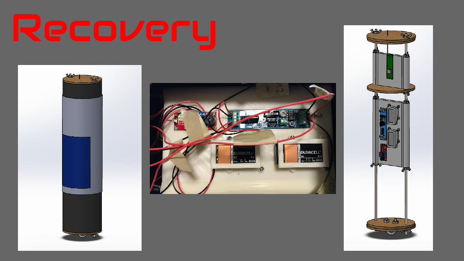
Recovery
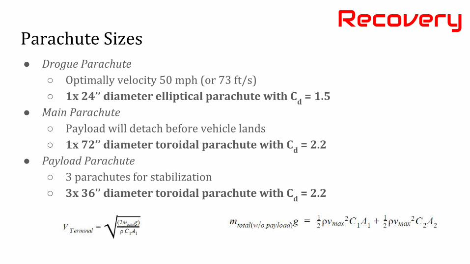
Parachute Sizes● Drogue Parachute
○ Optimally velocity 50 mph (or 73 ft/s)○ 1x 24’’ diameter elliptical parachute with C
d = 1.5
● Main Parachute○ Payload will detach before vehicle lands○ 1x 72’’ diameter toroidal parachute with C
d = 2.2
● Payload Parachute○ 3 parachutes for stabilization○ 3x 36’’ diameter toroidal parachute with C
d = 2.2
Recovery
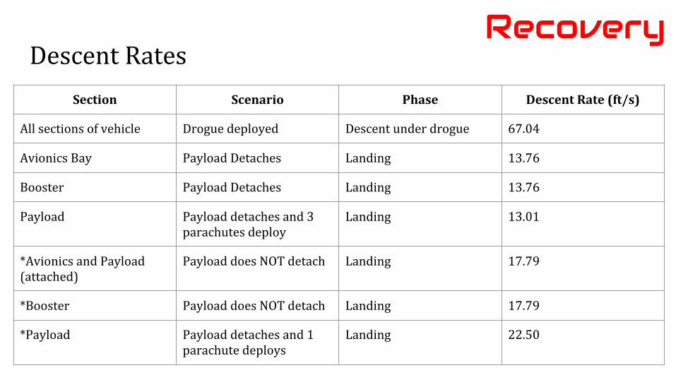
Descent RatesRecovery
Section Scenario Phase Descent Rate (ft/s)
All sections of vehicle Drogue deployed Descent under drogue 67.04
Avionics Bay Payload Detaches Landing 13.76
Booster Payload Detaches Landing 13.76
Payload Payload detaches and 3 parachutes deploy
Landing 13.01
*Avionics and Payload (attached)
Payload does NOT detach Landing 17.79
*Booster Payload does NOT detach Landing 17.79
*Payload Payload detaches and 1 parachute deploys
Landing 22.50
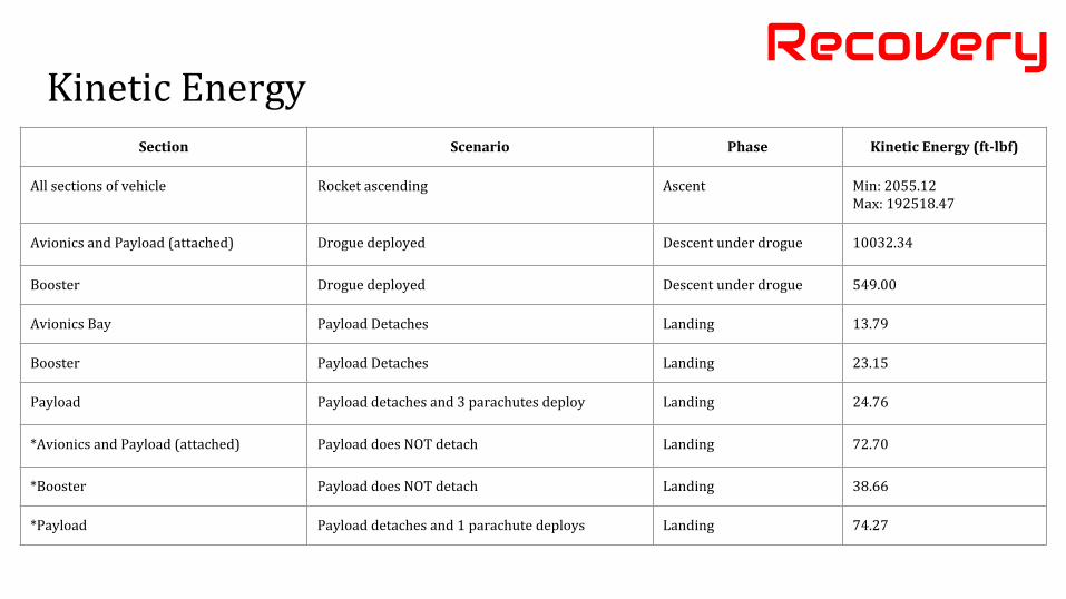
Kinetic EnergyRecovery
Section Scenario Phase Kinetic Energy (ft-lbf)
All sections of vehicle Rocket ascending Ascent Min: 2055.12Max: 192518.47
Avionics and Payload (attached) Drogue deployed Descent under drogue 10032.34
Booster Drogue deployed Descent under drogue 549.00
Avionics Bay Payload Detaches Landing 13.79
Booster Payload Detaches Landing 23.15
Payload Payload detaches and 3 parachutes deploy Landing 24.76
*Avionics and Payload (attached) Payload does NOT detach Landing 72.70
*Booster Payload does NOT detach Landing 38.66
*Payload Payload detaches and 1 parachute deploys Landing 74.27
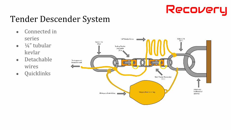
Tender Descender SystemRecovery
● Connected in series
● ¼” tubular kevlar
● Detachable wires
● Quicklinks
Recovery System TestsRecovery
Two major tests were performed for the recovery system, both of which were successful
● Tender descender tests○ Tested tender descender release combinations
● Ground tests for black powder charge size verification○ 1 4-40 shear pin
■ 4g for drogue■ 0.5g for main
○ 2 4-40 shear pin■ 2g for payload
1. Airframe2. Payload3. Recovery4. Vehicle Interfaces5. Flight Simulations6. Full-Scale Flight7. Project Plan8. Full-Scale Reflight
Presentation Map

Vehicle Interfaces
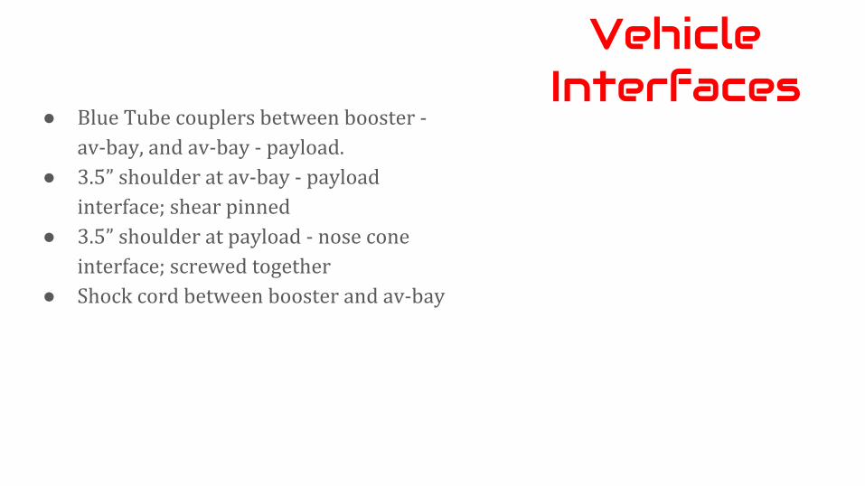
Vehicle Interfaces
● Blue Tube couplers between booster - av-bay, and av-bay - payload.
● 3.5” shoulder at av-bay - payload interface; shear pinned
● 3.5” shoulder at payload - nose cone interface; screwed together
● Shock cord between booster and av-bay
1. Airframe2. Payload3. Recovery4. Vehicle Interfaces5. Flight Simulations6. Full-Scale Flight7. Project Plan8. Full-Scale Reflight
Presentation Map
Flight Simulations
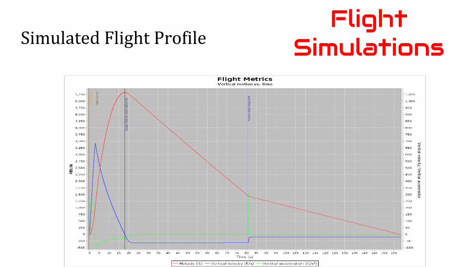
Simulated Flight ProfileFlight
Simulations
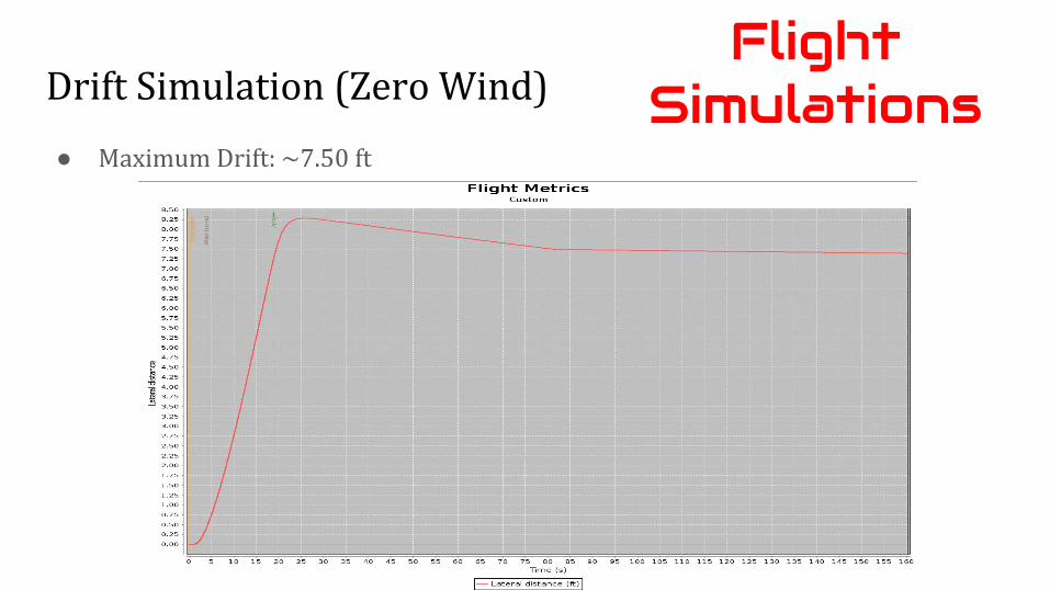
Drift Simulation (Zero Wind)
● Maximum Drift: ~7.50 ft
Flight Simulations
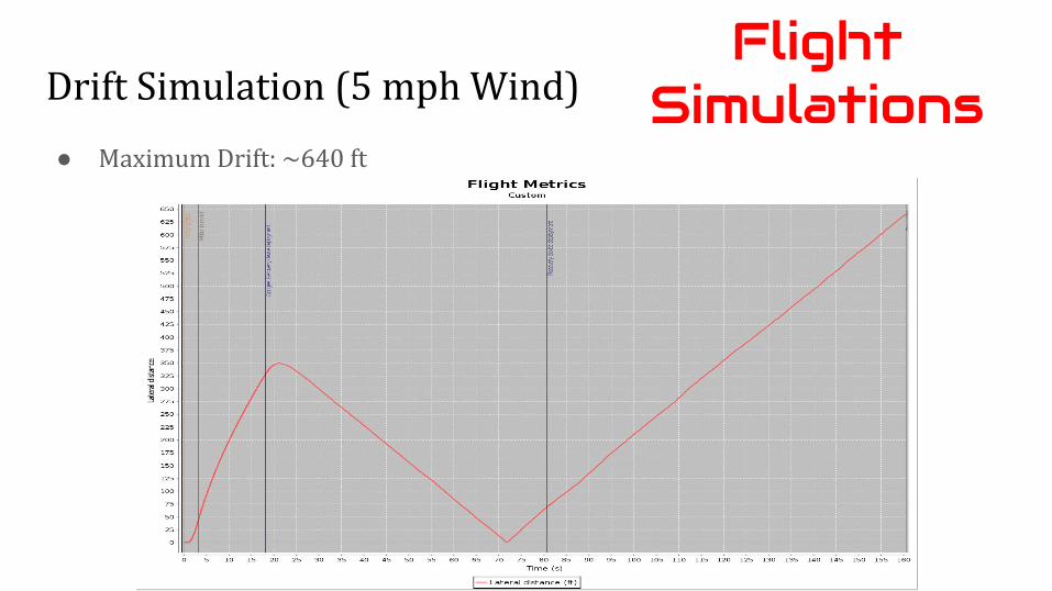
Drift Simulation (5 mph Wind)
● Maximum Drift: ~640 ft
Flight Simulations
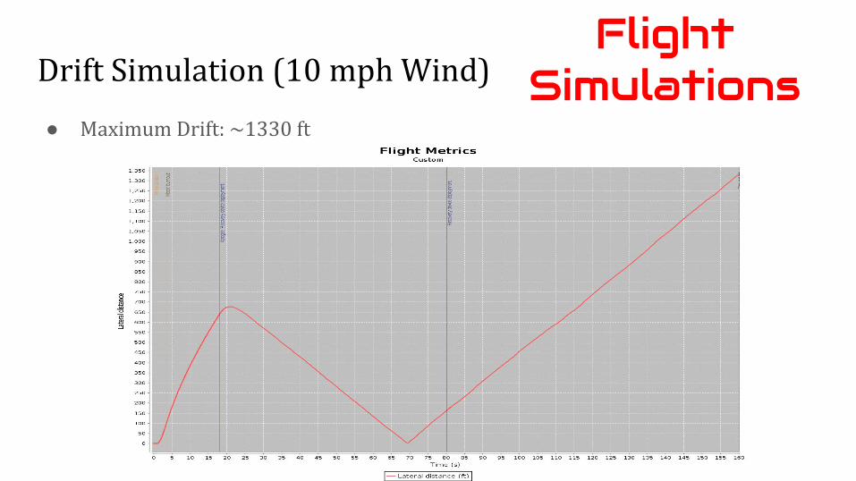
Drift Simulation (10 mph Wind)
● Maximum Drift: ~1330 ft
Flight Simulations
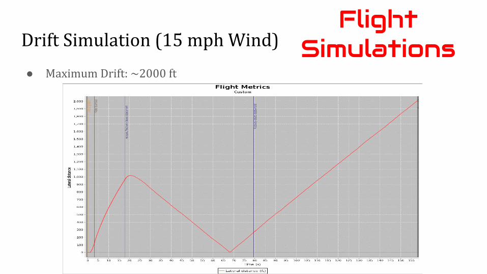
Drift Simulation (15 mph Wind)
● Maximum Drift: ~2000 ft
Flight Simulations
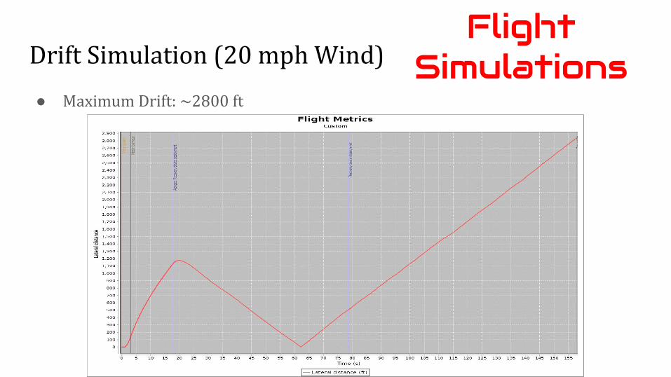
Drift Simulation (20 mph Wind)
● Maximum Drift: ~2800 ft
Flight Simulations
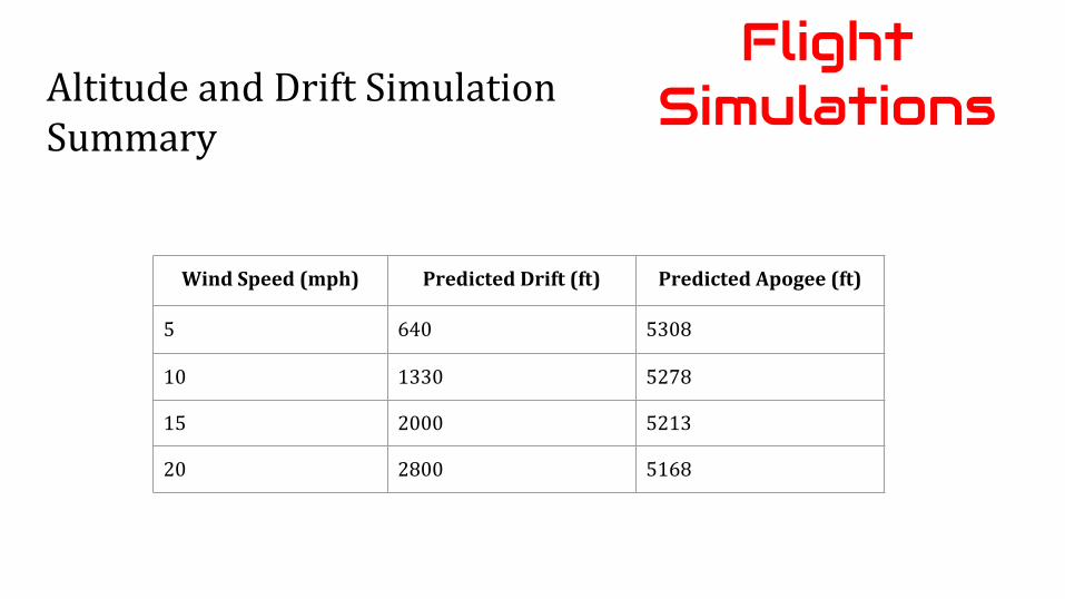
Altitude and Drift SimulationSummary
Flight Simulations
Wind Speed (mph) Predicted Drift (ft) Predicted Apogee (ft)
5 640 5308
10 1330 5278
15 2000 5213
20 2800 5168
1. Airframe2. Payload3. Recovery4. Vehicle Interfaces5. Flight Simulations6. Full-Scale Flight7. Project Plan8. Full-Scale Reflight
Presentation Map
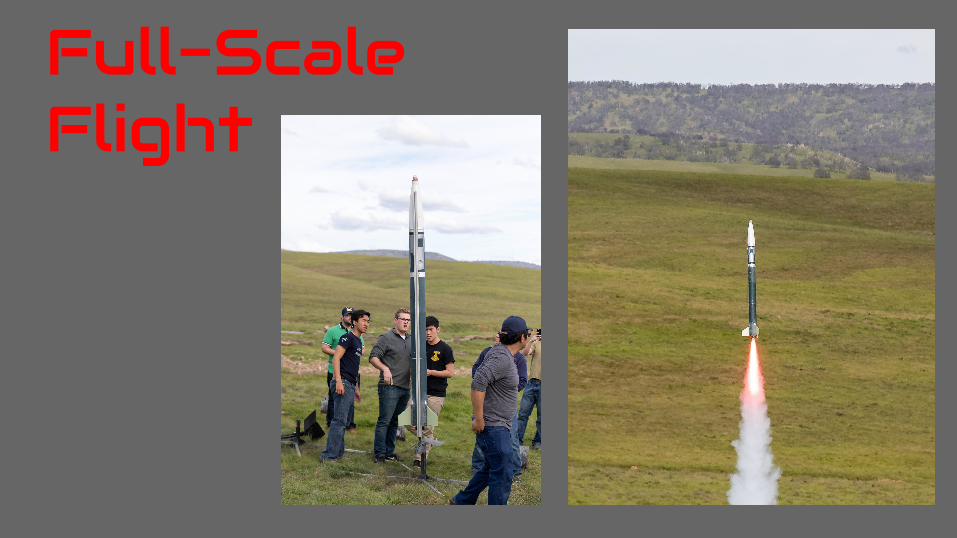
Full-Scale Flight
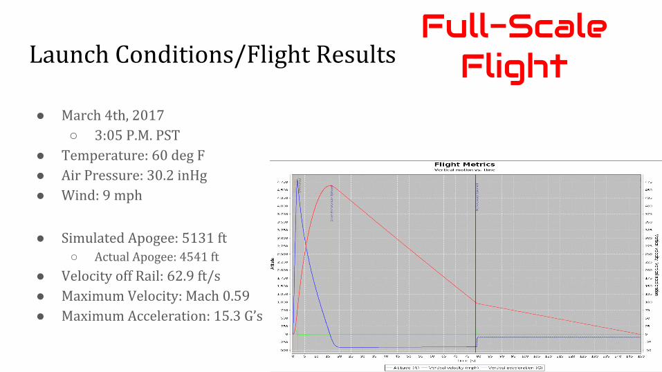
Launch Conditions/Flight Results
● Simulated Apogee: 5131 ft○ Actual Apogee: 4541 ft
● Velocity off Rail: 62.9 ft/s● Maximum Velocity: Mach 0.59● Maximum Acceleration: 15.3 G’s
● March 4th, 2017○ 3:05 P.M. PST
● Temperature: 60 deg F● Air Pressure: 30.2 inHg● Wind: 9 mph
Full-Scale Flight
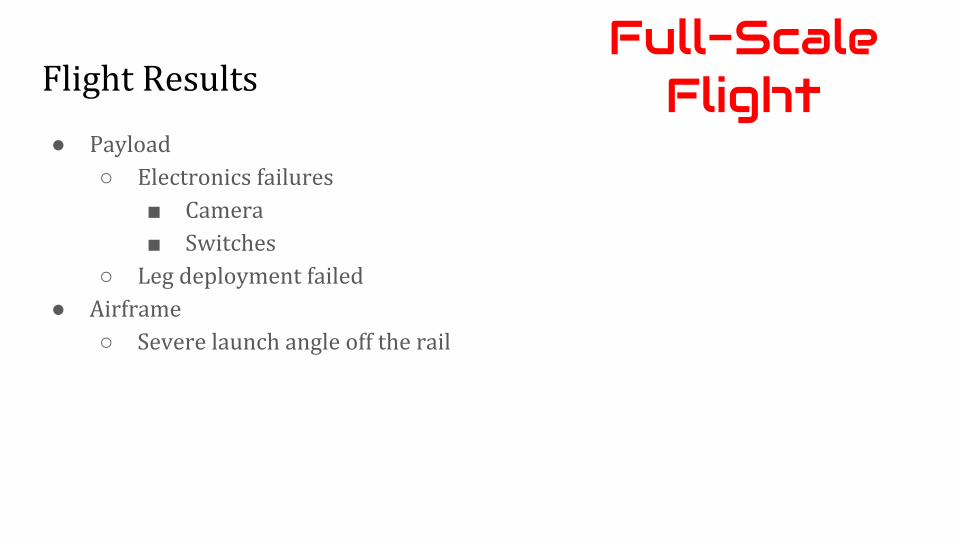
Flight Results
● Payload○ Electronics failures
■ Camera■ Switches
○ Leg deployment failed● Airframe
○ Severe launch angle off the rail
Full-Scale Flight
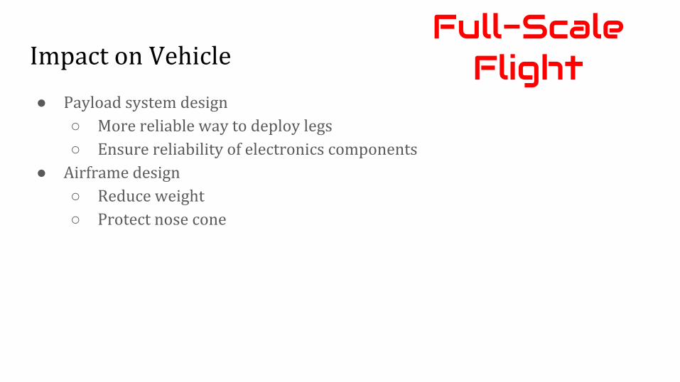
Impact on Vehicle
● Payload system design○ More reliable way to deploy legs○ Ensure reliability of electronics components
● Airframe design○ Reduce weight○ Protect nose cone
Full-Scale Flight
1. Airframe2. Payload3. Recovery4. Vehicle Interfaces5. Flight Simulations6. Full-Scale Flight7. Project Plan8. Full-Scale Reflight
Presentation Map
Project Plan
Test Plans and Procedures
Payload:
● Drop tests● Landing Leg Deployment Tests
○ Led to many necessary design modifications● Videos of both on our YouTube channel
Project Plan
Test Plans and Procedures
Electrical:
● Target Detection
Airframe:
● Durability Testing○ Fins & Nosecone Tip○ Water resilience
Project Plan
Requirement Verification: Vehicle
● All design requirements fulfilled○ Full-scale rocket successfully flown and recovered
● Team Derived Requirements largely focused on quality of construction
Project Plan
Requirement Verification: Recovery
● All design requirements fulfilled○ Full-scale rocket successfully flown and recovered
● Team Derived Requirements largely focused on safety and damage mitigation
Project Plan
Requirement Verification: Payload
● Some performance requirements are yet to be fulfilled○ Full-scale payload to be flown again to fulfill these
requirements● Team Derived Requirements largely focused on robustness
of ability to be recovered safely and land/remain upright
Project Plan
1. Airframe2. Payload3. Recovery4. Vehicle Interfaces5. Flight Simulations6. Full-Scale Flight7. Project Plan8. Full-Scale Reflight
Presentation Map
Full Scale Reflight
Flight Results● Launch Rail Issue
○ Nose cone fell○ Launch rail fell○ Single payload leg opened leading to single parachute deployment
Full-Scale Reflight
Impact on Vehicle
● Airframe○ Minor damage to booster section
■ Fixing with fiberglass○ Minor damage to fillets
Full-Scale Reflight
Impact on Vehicle
● Recovery○ Minor damage to door and airframe
■ Fixing with fiberglass ○ Sled cracked
■ Printing new sled○ All avionics bay electronics are working properly and have experienced
no damage○ Main and drogue parachute in perfect condition○ One payload parachute experienced burn damage
■ Purchasing new recovery parachute
Full-Scale Reflight
Impact on Vehicle (Recovery)Full-Scale Reflight
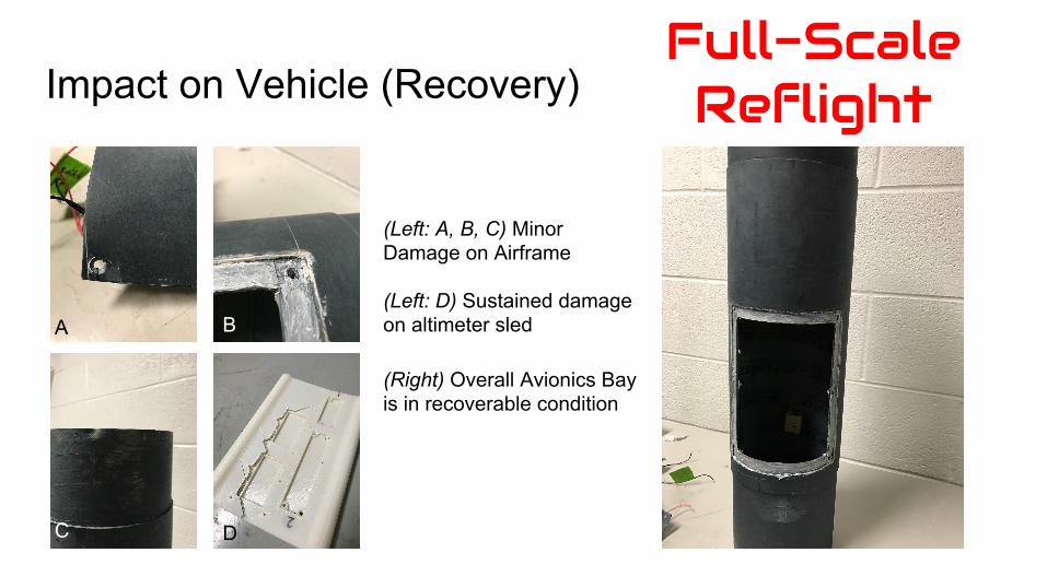
(Left: A, B, C) Minor Damage on Airframe
(Left: D) Sustained damage on altimeter sled
(Right) Overall Avionics Bay is in recoverable condition
A
DC
B
Impact on Vehicle● Payload
○ Rebuild■ Internal pvc + rail structure reusable■ Reinforce walls with fiberglass
○ Improve tolerances■ Manufacture more parts with computer
assistance (3D printing, laser cutting)○ Electronics
■ Make software more resilient to extraordinary conditions that turn off the Pi
Full-Scale Reflight
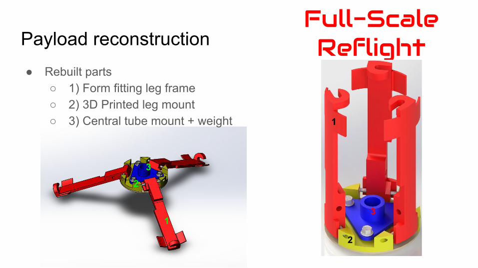
Payload reconstructionFull-Scale Reflight
1
2
31
2
3
● Rebuilt parts○ 1) Form fitting leg frame○ 2) 3D Printed leg mount○ 3) Central tube mount + weight
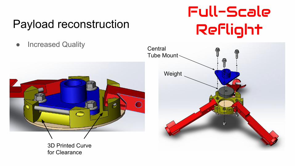
Payload reconstruction● Increased Quality
Full-Scale Reflight
Weight
Central Tube Mount
3D Printed Curve for Clearance

Questions?

Thank You!