Embed Size (px)
Citation preview
AiResearch Report No. 8 1 * 1 8 3 3 4
PO W ER C O N D IT IO N IN G H A R D W A R E FOR A C T R A C T IO N B A S E D O N U T IL IZ A T IO N O F T L R V
H A R D W A R E A N D T E C H N O L O G Y
AiResearch Manufacturing C o m p a n y 2 5 2 5 W . 190th Street Torrance, C A 9 0 5 0 9
D E C E M B E R 1981
FINAL REPORT
Document Is available to the U.S, public through the National Technical Information Service,
Springfield, Virginia 22161.
Prepared for
U.S. DEPARTMENT OF TRANSPORTATIONFEDERAL RAILROAD ADMINISTRATION
400 Seventh Street S W Washington, D.C. 20590
04 - Locomotives------------------- >V
Technical Report Documentation Page
1. Report No. 2. Government Accession No. 3. Recipient's Catalog No.
4. T i t l e and S u b t i t le
POWER CONDITIONING HARDWARE FOR AC TRACTION BASED ON THE UTILIZATION OF TLRV HARDWARE AND TECHNOLOGY
5. Report DateDecember 1981
6. Performing Organization Code
7. Author s)Graham W. McLean
8. Performing Organization Report No.81-18334
9. Performing Organization Name and AddressAiResearch Manufacturing Company 2525 W. 190th Street Torrance, CA 90509
10. Work Unit No. (TRAIS)11. Contract or Grant No.
DOT-FR-9132
12. Sponsoring Agency Name and AddressU.S. Department of Transportation Federal Railroad Administration 400 Seventh Street SW Washington. D.C. 20590___________
13. Type of Report and Period CoveredFinal Report October 1979 to December 1981
14. Sponsoring Agency Code
15. Supplementary Notes
16. AbstractThis final report records the findings of an application study that
investigated the feasibility of hardware and technology transfer to railroad traction of a multimegawatt power conditioning unit previously developed under sponsorship of the Department of Transportation. Various converter configurations capable of fulfilling the demanding traction requirements are presented. These converter drives are required to produce high starting torque combined with low torque pulsation and to demonstrate high efficiency. They are variants of the standard Graetz Bridge. These variants— all current-source converters— form three basic groups: (a) PWM (b) multibridge and (c) hidden-link. Theysupply either induction or synchronous traction motors and use either self- or machine commutation. A design and experimental program is proposed to compare selected converter drives both at subscale and full-scale levels. ■ Also described is an experimental investigation into the feasibility of separating the boiling pool and condenser if two-phase Freon cooling of power semiconductors is used.
17. Key WordsRailroad traction Power converters AC traction motors Torque pulsation Two-phase cooling
18. Disfribution StatementDocument is available to the U.S. public through the National Technical Information Service, Springfield, Virginia 22161
19. Security Classif. (of this report)Unclassified
20. Security Classif. (of this paga)Unclassified
21* No. of P ages227
22. Prie.
Form D O T F 1700.7 (8-72) Reproduction of completed page authorized

NOTICE
This document is disseminated under the sponsorship of the Department of Transportation in the interest of information exchange. The United States Government assumes no liability for the contents or use thereof.
PREFACE
This final report records the findings of an application study that investigated the feasibility of hardware and technology transfer to railroad traction of a multimegawatt power conditioning unit previously developed under sponsorship of the Department of Transportation. The report is in two parts:Part I, consisting of Section 1, provides an executive summary and recommendations; Part II, consisting of Sections 2 through 11, contains the technical presentation. Appendixes A through H furnish detailed supporting data.
The program was accomplished under the guidance of Mr. Matthew Guarino, Jr., Manager for Electrical Traction R&D, Office of Research and Development, Federal Railroad Administration, U.S. Department of Transportation.
The work reported herein was carried out in the Rapid Transit and Electrical Power Systems Department of AiResearch Manufacturing Company, a division of The Garrett Corporation. Mr. C. Weinstein is Chief Engineer of the department. Technical guidance was provided by Dr. G. Kalman, Engineering Supervisor. The principal author, Dr. G. W. McLean, received significant technical contributions from Mr. R. A. Bevan, Mr. R. A. Van Eck, and Mr. J. Kim.
i i i
TABLE OF CONTENTS
PART I:
1. EXECUTIVE SUMMARY 1-1
PART II:
2. CANDIDATE STATIC POWER CONDITIONING SYSTEMS 2-1
3. CANDIDATE AC TRACTION MOTORS 3-1
4. INFLUENCE OF HARMONICS ON MOTOR PERFORMANCE 4-1
5. OPERATING CONDITIONS 5-1
6. LOCOMOTIVE TRACTION 6-1
7. SYSTEM UPGRADING 7-1
3. SYSTEM DEFINITION FOR LOCOMOTIVE APPLICATION ' 8-1
9. CONTROL OF LINE-COMMUTATED INVERTER USING MACHINE TERMINAL SENSING
9-1
Exhibit 9A: Test Plan for an Investigation Into Control of Inverter/Machine Combinations Using Machine Terminal Sensing
9A-
10. TWO-PHASE COOLING TECHNIQUES 10-
Exhibit 10A: Test Plan for Freon Two-Phase Cooling Experiment
10 A-
11. CONCLUSIONS 11-
APPENDIXES
A TECHNICAL FEATURES AND CHARACTERISTICS OF EXISTING AC PROPULSION SYSTEM
;> i i—*
B VOLTAGE AND CURRENT WAVEFORMS IN LCI/SYNCHRONOUS MACHINE SYSTEMS
B-l
C THE HIDDEN-LINK CONVERTER C-l
D CAPACITOR-ASSISTED CURRENT-SOURCE INVERTER WITH SERIES BLOCKING DIODES SUPPLYING AN ASYNCHRONOUS TRACTION MOTOR
D-l
iv
TABLE OF CONTENTS (Continued)
E CAPACITOR-ASSISTED CURRENT-SOURCE INVERTER SUPPLYING E-lAN ASYNCHRONOUS TRACTION MOTOR WITH THE COMMUTATING CAPACITOR IN THE NEUTRAL CIRCUIT
F HARMONIC REPRESENTATION OF CURRENTS IN THE STATOR WINDINGS F-lOF A Q-PHASEBAND SYMMETRICAL MACHINE
G TORQUE PULSATIONS G-l
H ANALOGUE COMPUTER EQUATIONS H-l
LIST OF FIGURES
Figure 1-1 SYNCHRONOUS CONDENSER, 10 MVA 1-4
Figure 1-2 PHASE-DELAY RECTIFER, 6 MVA 1-4
Figure 1-3 INVERTER, 6 MW 1-5
Figure 1-4 DIRECT LIQUID COOLING 1-5
Figure 1-5 THYRISTOR MODULE 1-6
Figure 1-6 SERIES/PARALLEL CONNECTION OF MOTOR COIL GROUPS 1-38
Figure 1-7 BASIC CONVERTER CONNECTION FOR THREE- AND SIX-PHASE SYSTEMS 1-39
Figure 1-8 ALTERNATE SIX-PHASE SERIES BRIDGE CONNECTION 1-40
Figure 1-9 PROGRAM PERSPECTIVES 1-41
Figure 2-1 BASELINE CONFIGURATION 2-3
Figure 2-2 LINE-COMMUTATED INVERTER TO SUPPLY SYNCHRONOUS TRACTION 2-4MOTORS
Figure 2-3 IMPROVEMENT OF WAYSIDE SUPPLY POWER FACTOR 2-6
Figure 2-4 USE OF TWO CHOPPERS AND DUPLEX INVERTER 2-8
Figure 2-5 OVERLAP ANGLE OF INVERTER ' 2-9
Figure 2-6 COMMUTATION LIMIT 2-10
Figure 2-7 TWO INVERTERS SUPPLY A SIX-PHASE MOTOR 2-11
Figure 2-8 STARTING A LINE-COMMUTATED INVERTER WITH FREEWHEELING 2-12THYRISTOR
V
TABLE OF CONTENTS (Continued)
Figure 2-10 FORCED-COMMUTATION SCHEME IN HIDDEN-LINK CONVERTER 2-14
Figure 2-11 COMMON PARALLEL-CAPACITOR-COMMUTATED CIRCUIT 2-15
Figure 2-12 OUTPUT WAVEFORM 2-16
Figure 2-13 TORQUE HARMONICS FOR THREE- AND SIX-PHASE MOTORS 2-18
Figure 2-14 MODIFIED CURRENT-SOURCE INVERTER 2-19
Figure 2-15 CAPACITOR-ASSISTED CURRENT-SOURCE INVERTER 2-21
Figure 3-1 THE UNITY POWER FACTOR MOTOR 3-3
Figure 3-2 WINDING CONNECTION 3-3
Figure 3-3 STATOR CURRENT LOADING AT UNITY POWER FACTOR 3-5
Figure 3-4 ROTATING TRANSFORMER EXCITER 3-7
Figure 3-5 LAMINATED ROTATING TRANSFORMER EXCITER 3-7
Figure 3-6 SUPPLY CIRCUIT FOR RELUCTANCE MOTOR 3-9
Figure 3-7 PERFORMANCE OF RELUCTANCE MOTOR 3-10
Figure 4-1 HARMONIC SPECTRA, EQUIVALENT CIRCUIT, AND VARIATION OF 4-3TORQUE WITH NUMBER OF PHASES
Figure 4-2 FLUX DISTRIBUTION 4-7
Figure 4-3 STATOR CURRENT WAVEFORM ' 4-7
Figure 5-1 WEIGHTING FUNCTIONS FOR VERTICAL AND LATERAL ACCELERATION 5-2 ASSESSMENTS
Figure 5-2 SPACE HARMONICS SPECTRA 5-5
Figure 5-3 TORQUE PULSATION CONTROL BY PULSE MODULATION 5-7
Figure 5-4 VARIATION OF PULSE SWITCHING FREQUENCY WITH OUTPUT FREQUENCY 5-8
Figure 5-5 IMPROVEMENT OF WAYSIDE SUPPLY POWER FACTOR 5-8
Figure 5-6 TWO-STEP INPUT BRIDGE 5-9
Figure 2-9 HIDDEN-LINK CONVERTERS 2-13
Figure 5-7 CONVERTER USING DC LINK MODULATION 5-10
vi
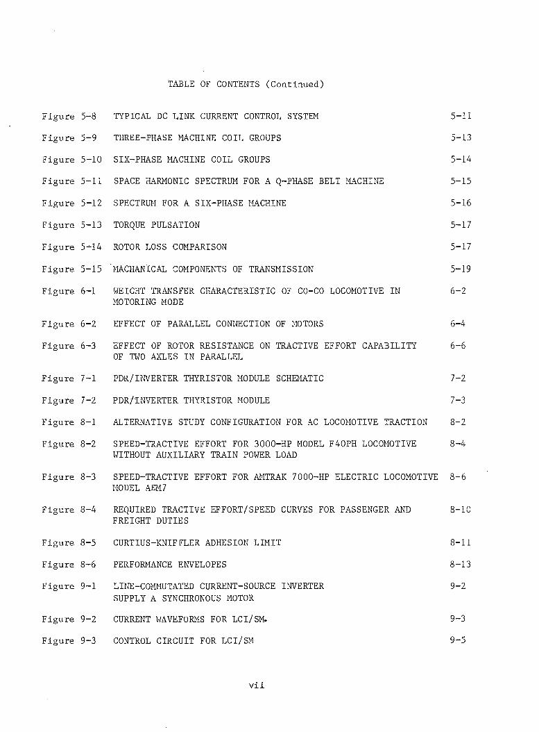
TABLE OF CONTENTS (Continued)
Figure 5-9 THREE-PHASE MACHINE COIL GROUPS 5-13
Figure 5-10 SIX-PHASE MACHINE COIL GROUPS 5-14
Figure 5-11 SPACE HARMONIC SPECTRUM FOR A Q-PHASE BELT MACHINE 5-15
Figure 5-12 SPECTRUM FOR A SIX-PHASE MACHINE 5-16
Figure 5-13 TORQUE PULSATION 5-17
Figure 5-14 ROTOR LOSS COMPARISON 5-17
Figure 5-15 MACHANICAL COMPONENTS OF TRANSMISSION 5-19
Figure 6-1 WEIGHT TRANSFER CHARACTERISTIC OF CO-CO LOCOMOTIVE IN 6-2MOTORING MODE
Figure 6-2 EFFECT OF PARALLEL CONNECTION OF MOTORS 6-4
Figure 6-3 EFFECT OF ROTOR RESISTANCE ON TRACTIVE EFFORT CAPABILITY 6-6OF TWO AXLES IN PARALLEL
Figure 7-1 PDR/INVERTER THYRISTOR MODULE SCHEMATIC 7-2
Figure 7-2 PDR/TNVERTER THYRISTOR MODULE 7-3
Figure 8-1 ALTERNATIVE STUDY CONFIGURATION FOR AC LOCOMOTIVE TRACTION 8-2
Figure 8-2 SPEED-TRACTIVE EFFORT FOR 3000-HP MODEL F40PH LOCOMOTIVE 8-4WITHOUT AUXILIARY TRAIN POWER LOAD
Figure 8-3 SPEED-TRACTIVE EFFORT FOR AMTRAK 7000-HP ELECTRIC LOCOMOTIVE 8-6 MODEL AEM7
Figure 8-4 REQUIRED TRACTIVE EFFORT/SPEED CURVES FOR PASSENGER AND 8-10FREIGHT DUTIES
Figure 8-5 CURTIUS-KNIFFLER ADHESION LIMIT 8-11
Figure 8-6 PERFORMANCE ENVELOPES 8-13
Figure 9-1 LINE-COMMUTATED CURRENT-SOURCE INVERTER 9-2SUPPLY A SYNCHRONOUS MOTOR
Figure 9-2 CURRENT WAVEFORMS FOR LCI/SM. 9-3
Figure 5-8 TYPICAL DC LINK CURRENT CONTROL SYSTEM 5-11
Figure 9-3 CONTROL CIRCUIT FOR LCI/SM 9-5
v i i
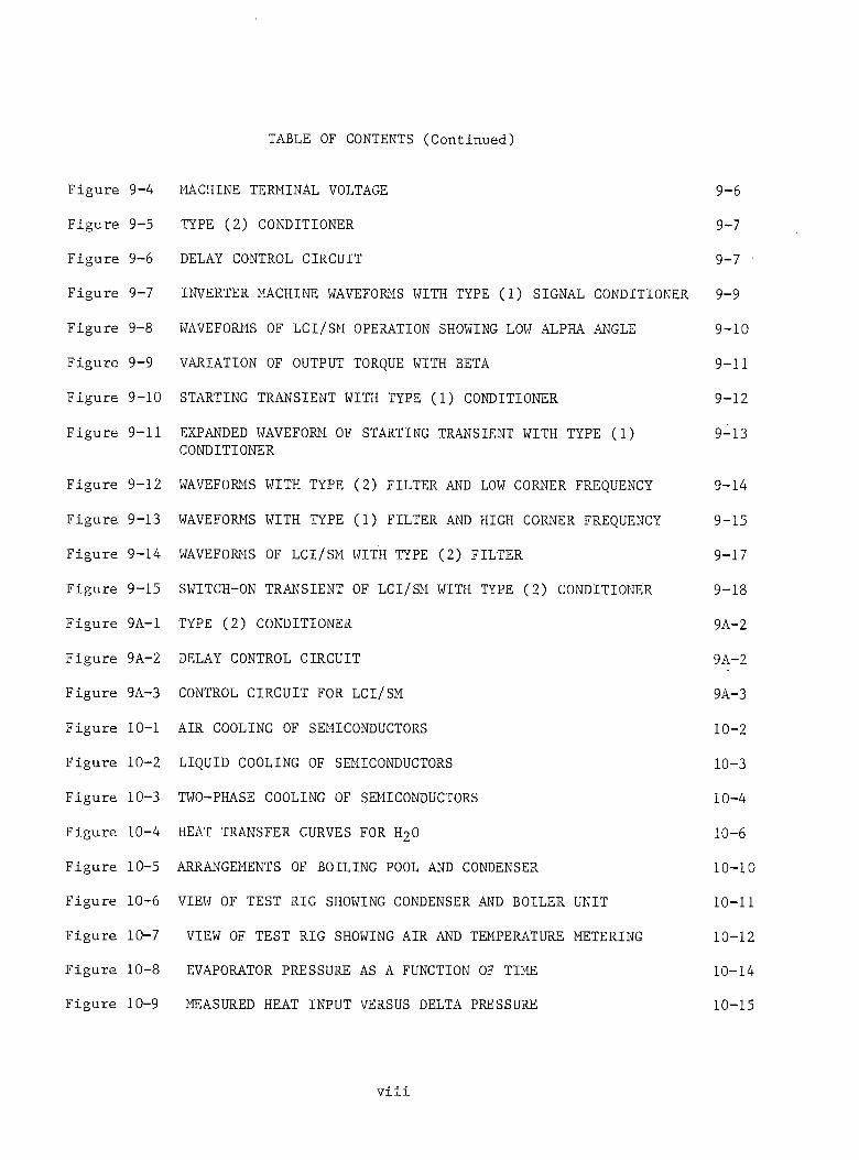
TABLE OF CONTENTS (Continued)
Figure 9-5 TYPE (2) CONDITIONER 9-7
Figure 9-6 DELAY CONTROL CIRCUIT 9-7 '
Figure 9-7 INVERTER MACHINE WAVEFORMS WITH TYPE (1) SIGNAL CONDITIONER 9-9
Figure 9-8 WAVEFORMS OF LCI/SM OPERATION SHOWING LOW ALPHA ANGLE 9-10
Figure 9-9 VARIATION OF OUTPUT TORQUE WITH BETA 9-11
Figure 9-10 STARTING TRANSIENT WITH TYPE (1) CONDITIONER 9-12
Figure 9-11 EXPANDED WAVEFORM OF STARTING TRANSIENT WITH TYPE (1) 9-13CONDITIONER
Figure 9-12 WAVEFORMS WITH TYPE (2) FILTER AND LOW CORNER FREQUENCY 9-14
Figure 9-13 WAVEFORMS WITH TYPE (1) FILTER AND HIGH CORNER FREQUENCY 9-15
Figure 9-14 WAVEFORMS OF LCI/SM WITH TYPE (2) FILTER 9-17
Figure 9-15 SWITCH-ON TRANSIENT OF LCI/SM WITH TYPE (2) CONDITIONER 9-18
Figure 9A-1 TYPE (2) CONDITIONER 9A-2
Figure 9A-2 DELAY CONTROL CIRCUIT 9A-2
Figure 9A-3 CONTROL CIRCUIT FOR LCI/SM 9A-3
Figure 10-1 AIR COOLING OF SEMICONDUCTORS 10-2
Figure 10-2 LIQUID COOLING OF SEMICONDUCTORS 10-3
Figure 10-3 TWO-PHASE COOLING OF SEMICONDUCTORS 10-4
Figure 10-4 HEAT TRANSFER CURVES FOR H20 10-6
Figure 10-5 ARRANGEMENTS OF BOILING POOL AND CONDENSER 10-10
Figure 10-6 VIEW OF TEST RIG SHOWING CONDENSER AND BOILER UNIT 10-11
Figure 10-7 VIEW OF TEST RIG SHOWING AIR AND TEMPERATURE METERING 10-12
Figure 10-8 EVAPORATOR PRESSURE AS A FUNCTION OF TIME 10-14
Figure 9-4 MACHINE TERMINAL VOLTAGE 9-6
Figure 10-9 MEASURED HEAT INPUT VERSUS DELTA PRESSURE 10-15
v i i i
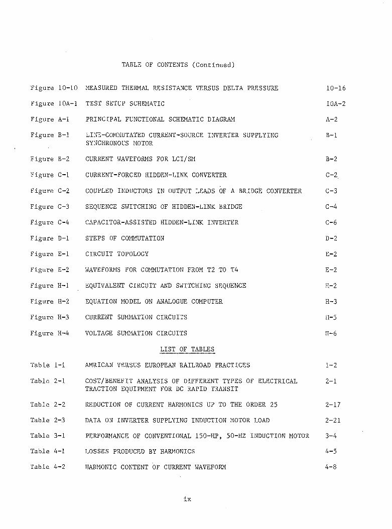
TABLE OF CONTENTS (Continued)
Figure 10A-1 TEST SETUP SCHEMATIC 10A-2
Figure A-l PRINCIPAL FUNCTIONAL SCHEMATIC DIAGRAM A-2
Figure B-l LINE-COMMUTATED CURRENT-SOURCE INVERTER SUPPLYING B-lSYNCHRONOUS MOTOR
Figure B-2 CURRENT WAVEFORMS FOR LCI/SM B-2
Figure C-l CURRENT-FORCED HIDDEN-LINK CONVERTER C-2.
Figure C-2 COUPLED INDUCTORS IN OUTPUT LEADS OF A BRIDGE CONVERTER C-3
Figure C-3 SEQUENCE SWITCHING OF HIDDEN-LINK BRIDGE C-4
Figure C-4 CAPACITOR-ASSISTED HIDDEN-LINK INVERTER C-6
Figure D-l STEPS OF COMMUTATION D-2
Figure E-l CIRCUIT TOPOLOGY E-2
Figure E-2 WAVEFORMS FOR COMMUTATION FROM T2 TO T4 E-2
Figure H-l EQUIVALENT CIRCUIT AND SWITCHING SEQUENCE H-2
Figure H-2 EQUATION MODEL ON ANALOGUE COMPUTER H-3
Figure H-3 CURRENT SUMMATION CIRCUITS H-5
Figure H-4 VOLTAGE SUMMATION CIRCUITS H-6
LIST OF TABLES
Table 1-1 AMRICAN VERSUS EUROPEAN RAILROAD PRACTICES 1-2
Table 2-1 COST/BENEFIT ANALYSIS OF DIFFERENT TYPES OF ELECTRICAL 2-1TRACTION EQUIPMENT FOR DC RAPID TRANSIT
Table 2-2 REDUCTION OF CURRENT HARMONICS UP TO THE ORDER 25 2-17
Table 2-3 DATA ON INVERTER SUPPLYING INDUCTION MOTOR LOAD 2-21
Table 3-1 PERFORMANCE OF CONVENTIONAL 150-HP, 50-HZ INDUCTION MOTOR 3-4
Table 4-1 LOSSES PRODUCED BY HARMONICS 4-5
Table 4-2 HARMONIC CONTENT OF CURRENT WAVEFORM 4-8
Figure 10-10 MEASURED THERMAL RESISTANCE VERSUS DELTA PRESSURE 10-16
ix
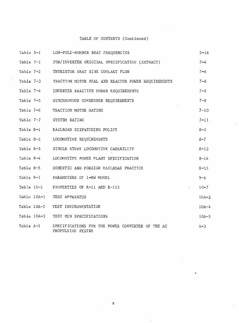
TABLE OF CONTENTS (Continued)
Table 5-1 LOW-POLE-NUMBER BEAT FREQUENCIES 5-16
Table 7-1 PDR/INVERTER ORIGINAL SPECIFICATION (EXTRACT) 7-4
Table 7-2 THYRISTOR HEAT SINK COOLANT FLOW 7-6
Table 7-3 TRACTION MOTOR REAL AND REACTOR POWER REQUIREMENTS 7-8
Table 7-4 INVERTER REACTIVE POWER REQUIREMENTS 7-9
Table 7-5 SYNCHRONOUS CONDENSER REQUIREMENTS 7-9
Table 7-6 TRACTION MOTOR RATING 7-10
Table 7-7 SYSTEM RATING 7-11
Table 8-1 RAILROAD DISPATCHING POLICY 8-5
Table 8-2 LOCOMOTIVE REQUIREMENTS 8-7
Table 8-3 SINGLE STUDY LOCOMOTIVE CAPABILITY 8-12
Table 8-4 LOCOMOTIVE POWER PLANT SPECIFICATION 8-14
Table 8-5 DOMESTIC AND FOREIGN RAILROAD PRACTICE 8-15
Table 9-1 PARAMETERS OF 1-MW MODEL 9-6
Table 10-1 PROPERTIES OF R-l1 AND R-113 10-7
Table 10A-1 TEST APPARATUS 10A-2
Table 10A-2 TEST INSTRUMENTATION 10A-4
Table 10A-3 TEST RUN SPECIFICATIONS 10A-5
Table A-l SPECIFICATIONS FOR THE POWER CONVERTER OF THE AC PROPULSION SYSTEM
A-3
x
XI
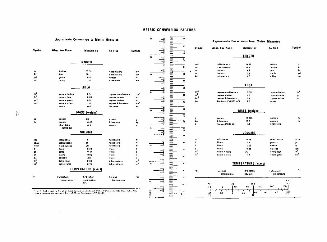
METRIC CONVERSION FACTORSApproximate Conversions to Metric Measures
Symbol When You Know Multiply by To Find Symbol
LENGTH
in in ches *2 .5 c e n tim e te rs cmf t fe e t 30 c e n tim e te rs cmyd yards 0 .9 m e te rs mm i m ile s 1 .6 k ilo m e te rs km
AREA
in 2 square in ch e s 6 .5 square c e n tim e te rs cm 2
f t 2 square fe e t 0 .09 square m e te rs m 2
V<l2square ya rds 0.B square m eters m2
m i2 square m ile s 2 .6 square k ilo m e te rs km *
a cres 0 .4 h e c ta re s ha
MASS (weight)
oz ounces 28 gram s 9lb pounds 0 .4 5 k ilo g ra m s kg
s h o rt tons 0 .9 to n n e s t(2000 lb)
VOLUME
ts p tea sp o o n s 5 m il l i l i t e r s m l
Tbsp ta b le sp o o n s 15 m i l l i l i t e r s ml
f l oz f lu id ounces 30 m i l l i l i t e r s ml
c cups 0.24 l ite r s 1
p t p in ts 0 .47 l ite r s 1
q t q u a rts 0 .95 l ite r s 1 .
ga l g a llo n s 3.8 l ite rs 1
f t 3 c u b ic fee t 0 .03 c u b ic m e te rs m3
yd 3 c u b ic ya rd s 0 .76 c u b ic m eters m3
TEMPERATURE (exact)
°F Fahrenhe it 5 /9 (a fte r C e ls iu s ° c
tem pera tu re s u b tra c tin g tem pera tu re
• l m - 2.54 (exactly). For other exact conversions and more detailed tables, see NBS Misc. Pulil. ?3G. Units ol Weights and Measures, Price S2.25, SD Catalog No. C '3 . 10:286.
ID _ == cn------ Z = i Approximate Conversions from Metric Measures
“ = M
- E= Symbol Whan You Know Multiply by To Find Symbol
- = = S
00 LENGTH__z = O
— -- — ----------- mm m ill im e te rs 0 .04 inches in
__ - = cm ce n tim e te rs 0 .4 inches in
— = =x m m ete rs 3 .3 fee t f t
- = = o> m m ete rs 1.1 yards yd
— i = km k ilo m e te rs 0 .6 m ile s mi
= = f -
- = AREA__r = (O
o>— cm * square ce n tim e te rs 0 .16 square inches in *
------- = = m m2 square m e te rs 1.2 square yards yd 2I = km 2 square k ilo m e te rs 0 .4 square m ile s m i2
— E 2 ha h e c ta re s (10 ,000 m2) 2 .5 acres
— z = COyi — E = MASS (weight)
— = =
__— 9 gram s 0.035 ounces oz
____ = kg k ilo g ra m s 2.2 pounds lb
—z = t to n n e s (1000 kg) 1.1 short tons
* ~z — ©
~ VOLUME- — <r>
— = == m l m i l l i l i t e r s 0 .03 f lu id ounces f l oz
- — 00 1 l i te r s 2.1 p in ts -v p tto — = 1 l i te rs 1.06 q u a rts q t
------- -- = t*. 1 l i te rs 0 .26 g a llo n s gal
- ------------ m 3 c u b ic m eters 35 c u b ic fee t f t 3— - — m3 c u b ic m eters 1.3 cu b ic yards Yd3
— = ^ -------(i>
to _z = in TEMPERATURE (exact)— E ~
«r °c C e ls iu s 9 /5 (then Fahrenhe it °F
__ ~ — tem pera tu re add 32) tem perature
- = Op
— = = °F 32 9 6 6 212--- -------- — 40 O | 40 60 120 160 200—
3 — " — r_* r r i — | I - ‘- T — I — T— — I , 1 1!L --------- — ------- - 4 0 -2 0 O 20 40 60 60 0

PARTI
EXECUTIVE SUMMARY
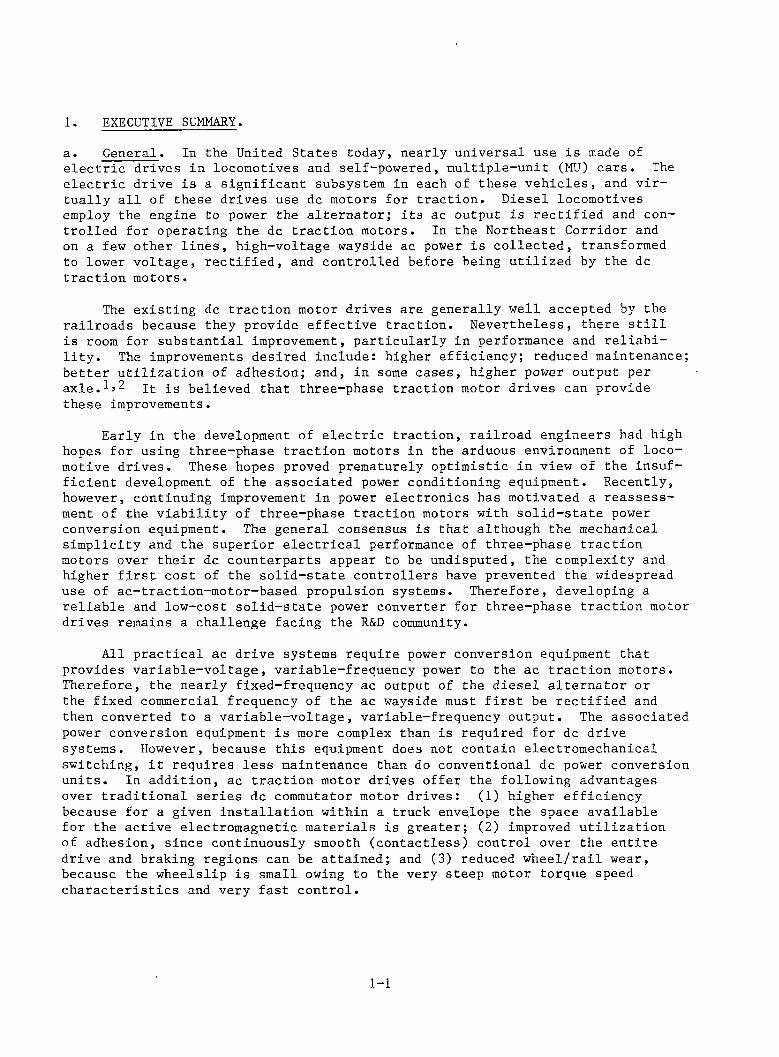
1. EXECUTIVE SUMMARY.a . General. In the United States today, nearly universal use is made of e le c tr ic drives in locomotives and self-powered, multiple-unit (MU) cars . The e le c tr ic drive is a significant subsystem in each of these vehicles, and v ir tually a l l of these drives use dc motors for traction . Diesel locomotives employ the engine to power the altern ator; its ac output is rectified and controlled for operating the dc traction motors. In the Northeast Corridor and on a few other lin es, high-voltage wayside ac power is collected , transformed to lower voltage, re ctifie d , and controlled before being utilized by the dc traction motors.
The existing dc traction motor drives are generally well accepted by the railroads because they provide effective traction . Nevertheless, there s t i l l is room for substantial improvement, particularly in performance and re lia b il i ty . The improvements desired include: higher efficiency; reduced maintenance; better u tilizatio n of adhesion; and, in some cases, higher power output per a x l e . i t is believed that three-phase traction motor drives can provide these improvements.
Early in the development of e le c tr ic traction , railroad engineers had high hopes for using three-phase traction motors in the arduous environment of locomotive drives. These hopes proved prematurely optimistic in view of the insufficien t development of the associated power conditioning equipment. Recently, however, continuing improvement in power electronics has motivated a reassessment of the v iab ility of three-phase traction motors with so lid -sta te power conversion equipment. The general consensus is that although the mechanical sim plicity and the superior e le c tr ica l performance of three-phase traction motors over their dc counterparts appear to be undisputed, the complexity and higher f i r s t cost of the so lid -state controllers have prevented the widespread use of ac-traction-motor-based propulsion systems. Therefore, developing a reliable and low-cost so lid -sta te power converter for three-phase traction motor drives remains a challenge facing the R&D community.
All p ractical ac drive systems require power conversion equipment that provides variable-voltage, variable-frequency power to the ac traction motors. Therefore, the nearly fixed-frequency ac output of the diesel altern ator or the fixed commercial frequency of the ac wayside must f i r s t be rectified and then converted to a variable-voltage, variable-frequency output. The associated power conversion equipment is more complex than is required for dc drive systems. However, because this equipment does not contain electromechanical switching, i t requires less maintenance than do conventional dc power conversion units. In addition, ac traction motor drives offer the following advantages over tradition al series dc commutator motor drives: (1) higher efficiencybecause for a given in stallation within a truck envelope the space available for the active electromagnetic materials is greater; (2) improved u tilizatio n of adhesion, since continuously smooth (contactless) control over the entire drive and braking regions can be attained; and (3) reduced w heel/rail wear, because the wheelslip is small owing to the very steep motor torque speed ch aracteristics and very fast control.
1-1
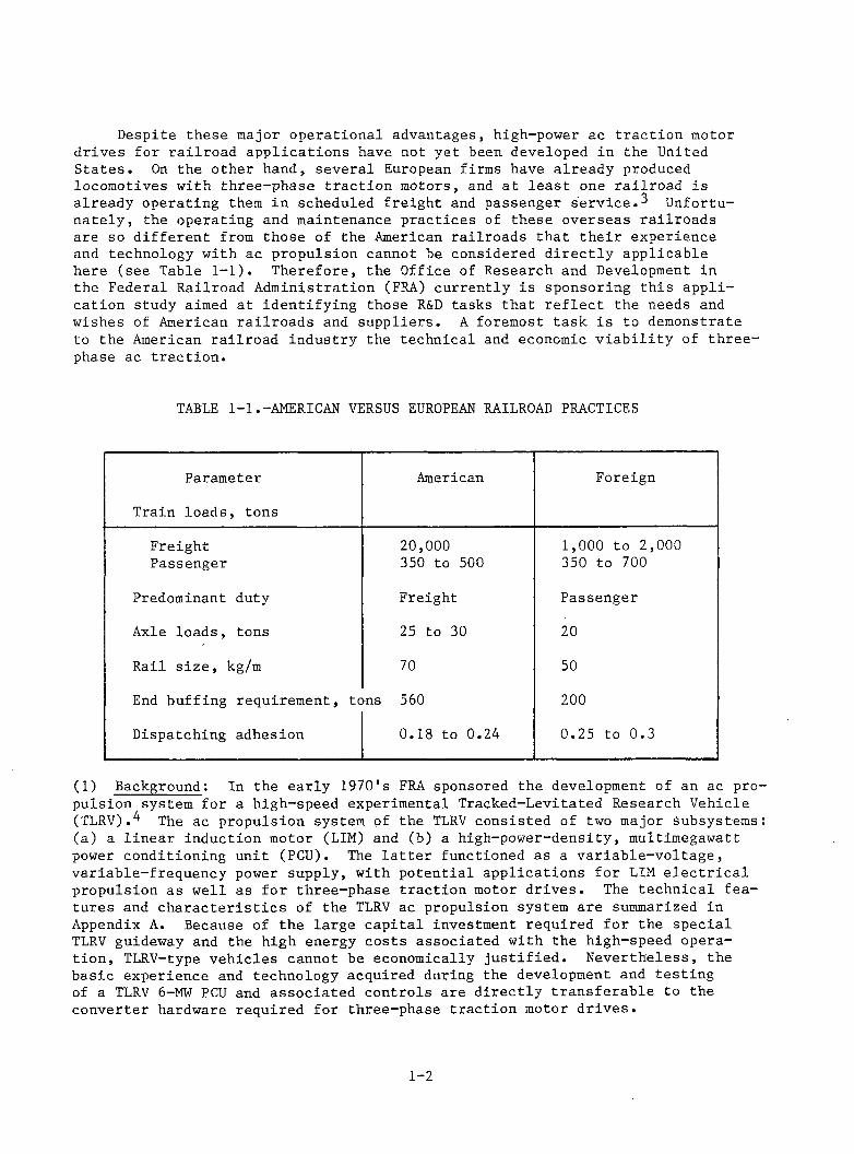
Despite these major operational advantages, high-power ac traction motor drives for railroad applications have not yet been developed in the United States. On the other hand, several European firms have already produced locomotives with three-phase traction motors, and at least one railroad is already operating them in scheduled freight and passenger service.^ Unfortunately, the operating and maintenance practices of these overseas railroads are so different from those of the American railroads that th eir experience and technology with ac propulsion cannot be considered d irectly applicable here (see Table 1 -1 ). Therefore, the Office of Research and Development in the Federal Railroad Administration (FRA) currently is sponsoring this application study aimed at identifying those R&D tasks that re fle c t the needs and wishes of American railroads and suppliers. A foremost task is to demonstrate to the American railroad industry the technical and economic v ia b ility of three- phase ac tractio n .
TABLE 1 -1 .-AMERICAN VERSUS EUROPEAN RAILROAD PRACTICES
(1) Background: In the early 1970's FRA sponsored the development of an ac propulsion system for a high-speed experimental Tracked-Levitated Research Vehicle (TLRV).^ The ac propulsion system of the TLRV consisted of two major subsystems: (a) a linear induction motor (LIM) and (b) a high-power-density, multimegawatt power conditioning unit (PCU). The la tte r functioned as a variable-voltage, variable-frequency power supply, with potential applications for LIM e le c tr ic a l propulsion as well as for three-phase traction motor drives. The technical features and ch aracteristics of the TLRV ac propulsion system are summarized in Appendix A. Because of the large capital investment required for the special TLRV guideway and the high energy costs associated with the high-speed operation, TLRV-type vehicles cannot be economically ju stified . Nevertheless, the basic experience and technology acquired during the development and testing of a TLRV 6-MW PCU and associated controls are d irectly transferable to the converter hardware required for three-phase traction motor drives.
1-2
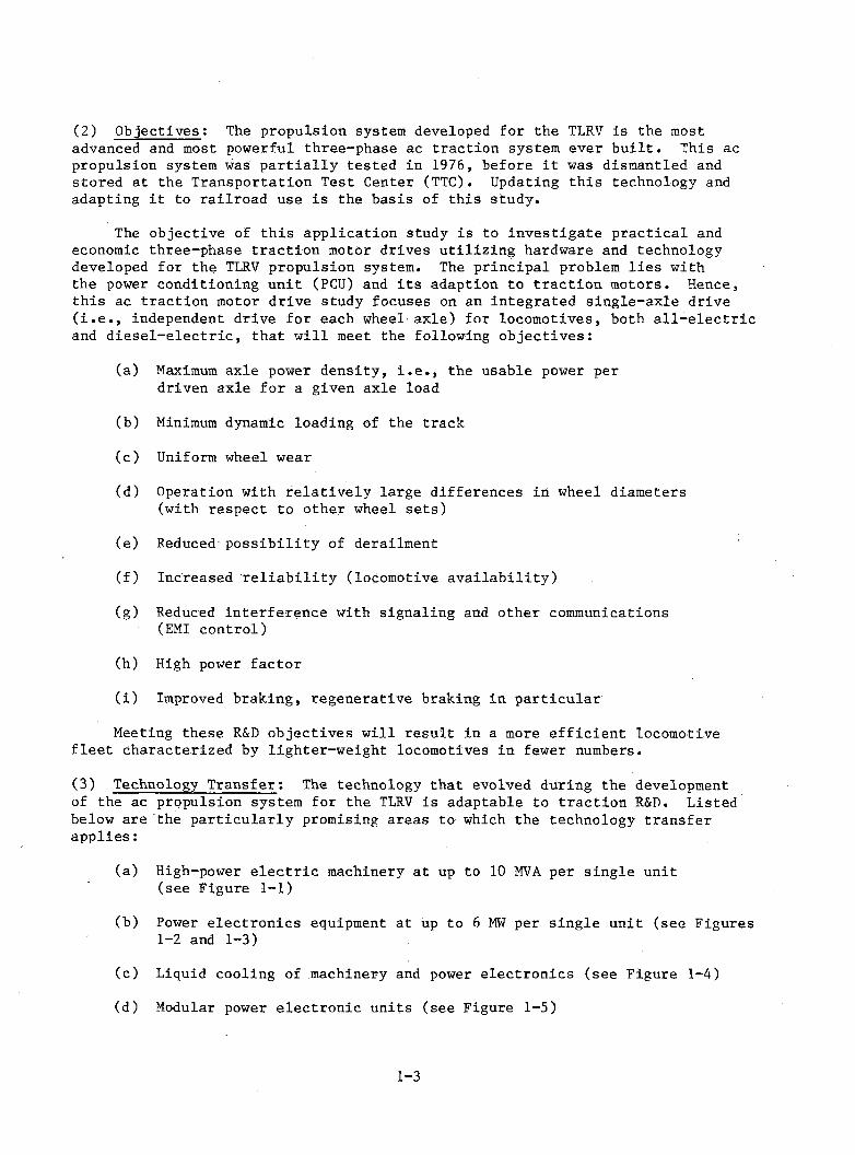
(2) Objectives: The propulsion system developed for the TLRV is the mostadvanced and most powerful three-phase ac traction system ever b u ilt. This ac propulsion system was p artia lly tested in 1976, before i t was dismantled and stored at the Transportation Test Center (TTC). Updating this technology and adapting i t to railroad use is the basis of this study.
The objective of this application study is to investigate p ractical and economic three-phase traction motor drives utilizing hardware and technology developed for the TLRV propulsion system. The principal problem lies with the power conditioning unit (PCU) and its adaption to traction motors. Hence, th is ac traction motor drive study focuses on an integrated single-axle drive ( i . e . , independent drive for each wheel axle) for locomotives, both a l l -e le c tr ic and d ie se l-e le c tric , that w ill meet the following objectives:
(a) Maximum axle power density, i . e . , the usable power per driven axle for a given axle load
(b) Minimum dynamic loading of the track
(c ) Uniform wheel wear
(d) Operation with relativ ely large differences in wheel diameters (with respect to other wheel sets)
(e) Reduced possibility of derailment
(f ) Increased re lia b ility (locomotive availab ility )
(g) Reduced interference with signaling and other communications (EMI control)
(h) High power factor
( i ) Improved braking, regenerative braking in particular
Meeting these R&D objectives will result in a more effic ien t locomotive fle e t characterized by lighter-weight locomotives in fewer numbers.
(3) Technology Transfer: The technology that evolved during the developmentof the ac propulsion system for the TLRV is adaptable to traction R&D. Listed below are the particu larly promising areas to which the technology transfer applies:
(a) High-power e le c tr ic machinery at up to 10 MVA per single unit (see Figure 1-1)
(b) Power electronics equipment at up to 6 MW per single unit (see Figures 1-2 and 1-3)
(c) Liquid cooling of machinery and power electronics (see Figure 1-4)
(d) Modular power electronic units (see Figure 1-5)
1 - 3
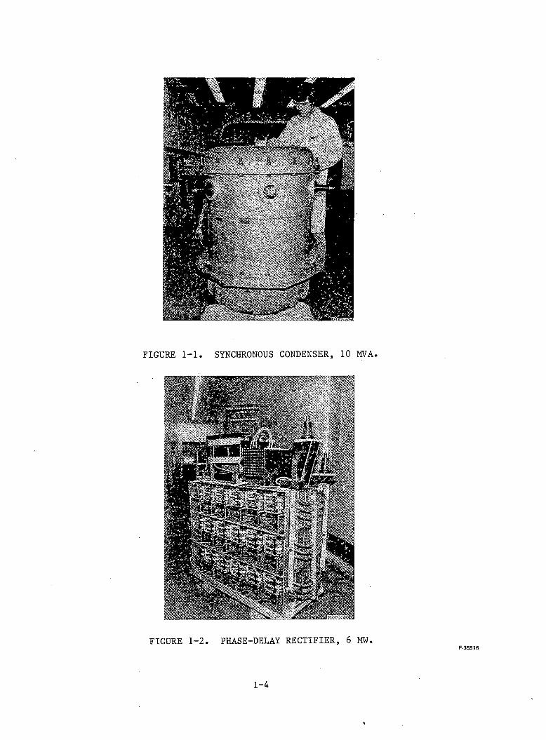
FIGURE 1-2. PHASE-DELAY RECTIFIER, 6 MW.F-35516
1-4
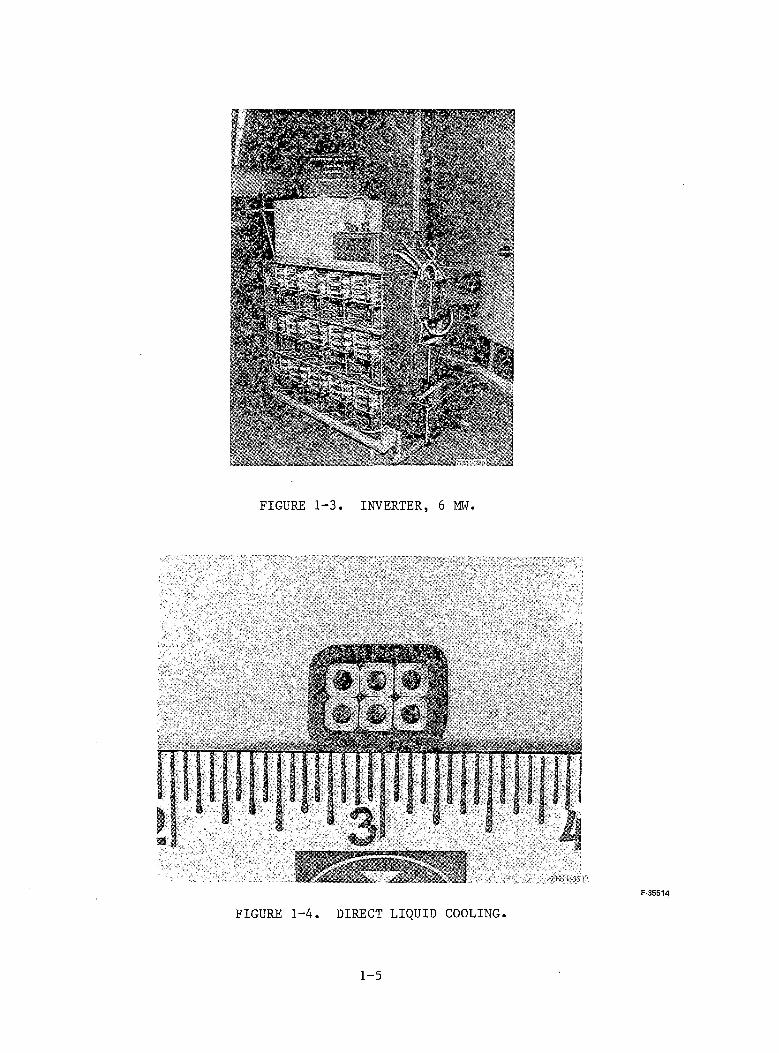
FIGURE 1-3. INVERTER, 6 MW.
FIGURE 1-4. DIRECT LIQUID COOLING.
1 - 5
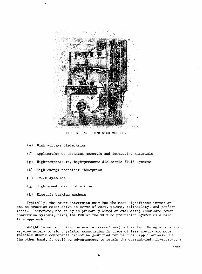
FIGURE 1-5. THYRISTOR MODULE.
(e) High voltage d ielectrics
(f) Application of advanced magnetic and insulating materials
(g) High-temperature, high-pressure d ielectric fluid systems
(h) High-energy transient absorption
( i ) Truck dynamics
(j ) High-speed power collection
(k) E lectric braking methods
Typically, the power conversion unit has the most significant impact on the ac traction motor drive in terms of co st, volume, r e lia b ility , and performance. Therefore, the study is primarily aimed at evaluating candidate power conversion systems, using the PCU of the TRLV ac propulsion system as a baseline approach. '
Weight is not of prime concern in locomotives; volume i s . Using a rotating machine solely to aid th yristor commutation in place of less costly and more reliable s ta tic components cannot be justified for railroad applications. On the other hand, i t would be advantageous to retain the current-fed, inverter-type
F-35S15
1-6
ch aracteristics of the TLRV power conditioning hardware, which (a) requires no separate commutation c ircu itry (e .g . , commutating capacitors, free wheeling diodes, current rate of rise lim iters); (b) uses re ctifie r-ty p e th yristors, as opposed to the more expensive inverter-types; and (c ) rides through certain faults and commutation failures without self-destruction . Because these features of the original power conversion approach should be retained, the study concentra tes on power-conditioning circu itry that can be derived d irectly from the TLRV hardware.
(4) Power Requirements; The various types of operations and applications result in an array of power requirements for propulsion systems. Locomotive power ratings also depend on the type of service intended, whether freight or passenger. For the purpose of the study, the nominal power requirements for the three-phase traction motor drive have to be defined.
Based on a preliminary analysis of applications of ac traction motor drives for locomotives, i t appears that a universal freight/passenger locomotive for conditions in the United States is not feasible. E le ctric freight locomotives need to develop 4,600 kW continuous ratings for 6 axles in order to haul a 1740- ton train up a 2-percent grade at a speed of 40 kph. High-speed e le c tric passenger locomotives need to develop a continuous rating of 6000 kW, but can use only 4 axles with ac drives in order to haul a 700-ton train up a 0.5-percent grade at 240 kph. In both cases the higher allowable adhesion coefficient of ac traction motor drives should be u tilized , along with a maximum axle load of 25 tons. Diesel locomotive power is limited to the maximum power of the prime mover; hence the axle power is limited. In this case, the better u tilization of adhesion of an ac traction motor should be coupled with improved truck design.
MU cars used for commuter service or very high speed operation require nominal axle ratings of 225 to 250 kW. In comparison, subway vehicles need 100 to 120 kW per axle , and lig h t-ra il vehicles (LRV) have typically 60 to 100 kW per axle nominal ratings.
(5) Conclusions: Based on the results of this study on the u tilizatio n ofexisting hardware and technology for ac traction R&D, the following conclusions have been reached:
a R&D should be aimed at e le c tric locomotives with three-phase ac traction motor drives.
o A universal freight/passenger locomotive is not p ractical in the United States.
e For future e le c tr ic a l locomotives with the proposed axle loads and power lev els, passenger locomotives should have 4 axles and freight locomotives should have 6 axles.
• Individual axle drives are preferred.
1-7

Static power converters should be made of identical modules for both freight and passenger locomotives.
• R&D should be aimed at current-source in verters.
• R&D should be aimed at completely suspended tractio n motors.
• Three-phase ac traction motor drives should be environmental-free.
• R&D should be aimed at methods and equipment that minimize maintenance requirements.
1-8
b. Su m m a r y of T e c hnical Presentation.
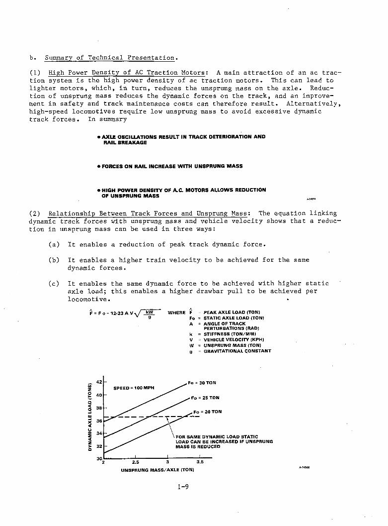
(1) High Power Density of AC Traction Motors: A main a ttractio n of an ac traction system is the high power density of ac traction motors. This can lead to lighter motors, which, in turn, reduces the unsprung mass on the axle . Reduction of unsprung mass reduces the dynamic forces on the track, and an improvement in safety and track maintenance costs can therefore re su lt. Alternatively high-speed locomotives require low unsprung mass to avoid excessive dynamic track forces. In summary
• AXLE OSCILLATIONS RESULT IN TRACK DETERIORATION AND RAIL BREAKAGE
• FORCES ON RAIL INCREASE WITH UNSPRUNG MASS
• HIGH POWER DENSITY OF A C . MOTORS ALLOWS REDUCTION OF UNSPRUNG MASS
(2) Relationship Between Track Forces and Unsprung Mass: The equation linking dynamic track forces with unsprung mass and vehicle velocity shows that a reduc tion in unsprung mass can be used in three ways:
(a) I t enables a reduction of peak track dynamic force.
(b) I t enables a higher train velocity to be achieved for the same dynamic forces.
(c) I t enables the same dynamic force to be achieved with higher s ta tic axle load; th is enables a higher drawbar pull to be achieved per locomotive. *
F = F n + 17-aa A V . / kW WHERE FV 3 Fo
A
kVWg
PEAK AXLE LOAD (TON) STATIC AXLE LOAD (TON) ANGLE OF TRACK PERTURBATIONS (RAD) STIFFNESS (TON/MM) VEHICLE VELOCITY (KPH) UNSPRUNG MASS (TON) GRAVITATIONAL CONSTANT
1-9

(3) Locomotive Requirements: If the American railroad system is to be e le c tr ified , the process will take many years and will require a period with both d ie se l-e le c tric and a ll -e le c tr ic locomotives in operation. A drive system that could be built into both types of locomotives would therefore be desirable, particu larly from a maintenance point of view. A specification for a locomotive was chosen with a common s ta tic axle load of 25 tons, which results in a 150-ton locomotive with 6 axles, or a 100-ton locomotive with 4 axles. The curves show that the performance of a freight train driven by a 6-axle locomotive would be limited by the adhesion lim it between wheel and track ; a passenger train would be limited by the power rating of the motor and supply.
m FREIGHT LOCO. PARAMETERS42 KPH MIIM. SPEED ON 2% GRADE 25 TON AXLE LOAD 150 TON C-C A R R A N G E M E N T 1740 TON ADHESION LIMITED TRAIN
• PASSENGER LOCO. PARAMETERS25 TON AXLE LOAD240 KPH MAX. SPEED ON 0.5% GRADE6 M W ALLOWS 700 TON TRAIN WITH NO ADHESION LIMIT
A14592
1-10
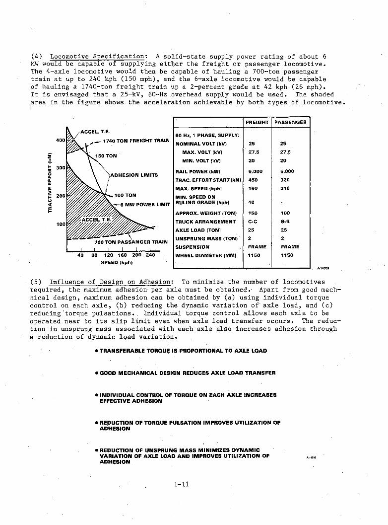
(4) Locomotive Specification: A solid -state supply power rating of about 6MW would be capable of supplying either the freight or passenger locomotive.The 4-axle locomotive would then be capable of hauling a 700-ton passenger train at up to 240 kph (150 mph), and the 6-axle locomotive would be capable of hauling a 1740-ton freight train up a 2-percent grade a t 42 kph (26 mph).I t is envisaged that a 25-kV, 60-Hz overhead supply would be used. The shaded area in the figure shows the acceleration achievable by both types of locomotive
FREIGHT PASSENGER
60 Hz, 1 PHASE, SUPPLY:NOMINAL VOLT (kV) 25 25
MAX. VOLT (kV) 27.5 27.5
MIN. VOLT (kV) 20 20RAIL POWER (kW) 6.000 6,000TRAC. EFFORT START (kN) 450 320
MAX. SPEED (kph) 160 240
MIN. SPEED ON RULING GRADE (kph) 40 -
APPROX. WEIGHT (TON) 150 100TRUCK ARRANGEMENT C-C B-B
AXLE LOAD (TON) 25 25
UNSPRUNG MASS (TON) 2 2SUSPENSION FRAME FRAME
WHEEL DIAMETER (MM) 1150 1150
(5) Influence of Design on Adhesion; To minimize the number of locomotives required, the maximum adhesion per axle must be obtained. Apart from good mech- nical design, maximum adhesion can be obtained by (a) using individual torque control on each axle , (b) reducing the dynamic variation of axle load, and (c) reducing torque pulsations.. Individual torque control allows each axle to be operated near to i ts slip lim it even when axle load transfer occurs. The reduction in unsprung mass associated with each axle also increases adhesion through a reduction of dynamic load variation.
• TRA N SFERA BLE TORQUE IS PROPORTIONAL TO A X LE LOAD
• GOOD M ECHAN ICAL DESIGN REDUCES A XLE LOAD TRA N SFER
• INDIVIDUAL CONTROL OF TORQUE ON EACH A X LE IN CREA SES EFFECTIVE ADHESION
• REDUCTION OF TORQUE PULSATION IMPROVES UTILIZATION OF ADHESION
• REDUCTION OF UNSPRUNG M ASS M INIM IZES DYNAM IC VARIATION OF A XLE LOAD AND IMPROVES UTILIZATION OF ADHESION
1-11
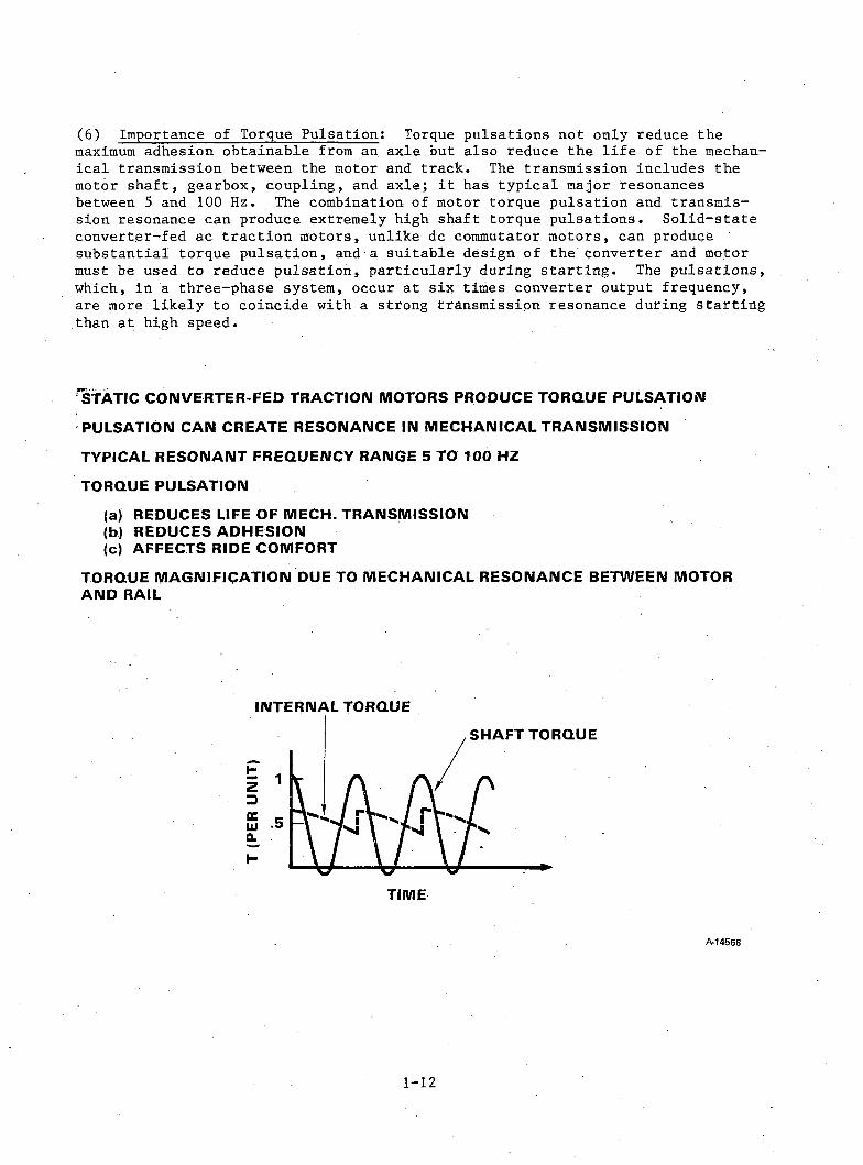
(6) Importance of Torque Pulsation: Torque pulsations not only reduce themaximum adhesion obtainable from an axle but also reduce the l i fe of the mechanica l transmission between the motor and track. The transmission includes the motor shaft, gearbox, coupling, and axle; i t has typical major resonances between 5 and 100 Hz. The combination of motor torque pulsation and transmission resonance can produce extremely high shaft torque pulsations. Solid-state converter-fed ac tractio n motors, unlike dc commutator motors, can produce substantial torque pulsation, and a suitable design of the converter and motor must be used to reduce pulsation, particularly during startin g . The pulsations, which, in a three-phase system, occur at six times converter output frequency, are more likely to coincide with a strong transmission resonance during starting than at high speed.
STATIC COIMVERTER-FED TRACTION MOTORS PRODUCE TORQUE PULSATION PULSATION CA N CREATE RESONANCE IN MECHANICAL TRANSMISSION TYPICAL RESONANT FREQUENCY RANGE 5 TO TOO HZ TORQUE PULSATION
(a) REDUCES LIFE OF MECH. TRANSMISSION(b) REDUCES ADHESION(c) AFFECTS RIDE COMFORT
TORQUE MAGNIFICATION DUE TO MECHANICAL R E SONANCE BETWEEN M O T O R A N D RAIL
INTERNAL TORQUE
A-14568
1-12
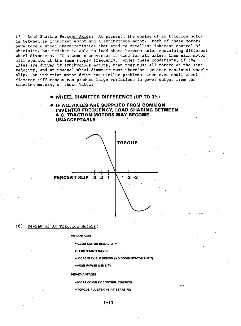
(7) Load Sharing Between Axles: At present, the choice of ac traction motoris between an induction motor and a synchronous motor. Both of these motors have torque speed ch aracteristics that produce excellent inherent control of wheelslip, but neither is able to load share between axles containing different wheel diameters. If a common converter is used for a ll axles, then each motor will operate at the same supply frequency. Under these conditions, i f the axles are driven by synchronous motors, then they must a ll rotate at the same velocity , and an unequal wheel diameter must therefore produce continual wheel- slip . An induction motor drive has similar problems since even small wheel diameter differences can produce large variations in power output from the traction motors, as shown below:
• W H E E L DIAMETER DIFFERENCE (UP TO 3%)• IF ALL AXLES A R E SUPPLIED F R O M C O M M O N
INVERTER FREQUENCY, LOAD S H ARING B E T W E E N A.C. TRACTION M O T O R S M A Y B E C O M E U N A C C E P T A B L E
(8) Review of AC Traction Motors:
ADVANTAGES
• GOOD MOTOR RELIABILITY
• LESS MAINTENANCE
• MORE FLEXIBLE DESIGN (NO COMMUTATOR LIMIT)
• HIGH POWER DENSITY
DISADVANTAGES
• MORE COMPLEX CONTROL CIRCUITS
• TORQUE PULSATIONS AT STARTING
1-13
(9) C riteria for Selection of Candidate Power Conditioning Units: Railroadrequirements produce a closely defined specification for the power conditioning unit and traction motor. These requirements reduce the possible converter systems that can be considered and also dictate the modifications necessary to standardize converter c ircu its if they are to be used as locomotive power conditioning units. The most important c r ite r ia for selection are listed below.
PERFORMANCE
• ABILITY TO PRODUCE HIGH STARTING TORQUE
• EFFICIENCY OF PCU A N D TRACTION MOTOR
• MAGNITUDE OF TORQUE PULSATIONS
• ABILITY TO A C C O M M O D A T E DIFFERENT W H EEL DIAMETERS
• ABILITY TO CONTROL WHEEL SLIP
• INPUT P O W E R FACTOR
COST
• CAPITAL COST
• MAINTENANCE COST A-14575
(10) S tatic Converters: The present study is concerned with current-sourceconverters because the TLRV converter used thyristor modules designed for this mode of operation. Many of the problems of locomotive converters are common to both current-fed and voltage-fed operation; however, i t appears that at present manufacturers are moving to the current-source converter for economical reasons.
• VOLTAGE - FED
• CURRENT - FED
A-14587
1-14
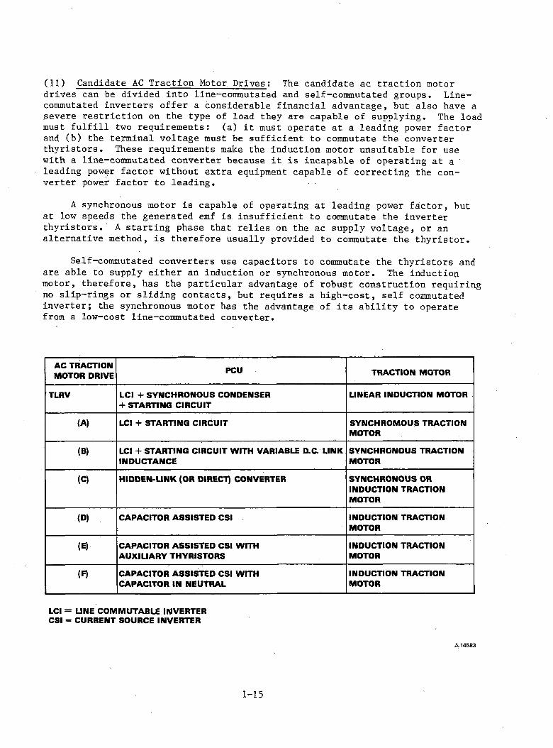
(11) Candidate AC Traction Motor Drives: The candidate ac traction motordrives can be divided into line-commutated and self-commutated groups. Line- commutated inverters offer a considerable financial advantage, but also have a severe restric tio n on the type of load they are capable of supplying. The load must fu lf i l l two requirements: (a) i t must operate at a leading power factorand (b) the terminal voltage must be sufficient to commutate the converter th yristors. These requirements make the induction motor unsuitable for use with a line-commutated converter because i t is incapable of operating at a leading power factor without extra equipment capable of correcting the converter power factor to leading.
A synchronous motor is capable of operating at leading power facto r, but at low speeds the generated emf is insufficient to commutate the inverter th yristors. A starting phase that relies on the ac supply voltage, or an alternative method, is therefore usually provided to commutate the th y risto r.
Self-commutated converters use capacitors to commutate the thyristors and are able to supply either an induction or synchronous motor. The induction motor, therefore, has the particular advantage of robust construction requiring no slip-rings or sliding contacts, but requires a high-cost, self commutated inverter; the synchronous motor has the advantage of i ts ab ility to operate from a low-cost line-commutated converter.
A C TRACT IO N M O TO R D R IV E
PCU T RACT IO N M O TO R
TLRV L C I + S Y N C H R O N O U S C O N D EN SER + ST A R T IN G C IR C U IT
L IN EA R IN D U CT IO N M O TOR
(A) LCI + ST A R T IN G C IR C U IT S Y N C H R O M O U S TRACT IO N M O TOR
(B) LCI + ST A R T IN G C IR C U IT W IT H V A R IA B LE D.C. L IN K IN D U C T A N C E
S Y N C H R O N O U S TRACT IO N M O TO R
(C) H ID D E N -L IN K (O R D IRECT) CONVERTER S Y N C H R O N O U S OR IN D U CT IO N TRACT IO N M O TO R
(D) C A PA C IT O R A S S IS T E D C S I IN D U C T IO N TRACT IO N M O TO R
(E) C A PA C IT O R A S S IS T E D C S I W IT H A U X IL IA R Y T H Y R IST O R S
IN D U CT IO N TRACT IO N M O TOR
m C A PA C IT O R A S S IS T E D C S I W IT H C A P A C IT O R IN N EU TRAL
IN D U CT IO N TRACT IO N M O TO R
LCI = LINE C O M M U T A B L E IN V ER TER C S I = CU R R EN T SO U R C E IN V ER TER
A-14583
1-15
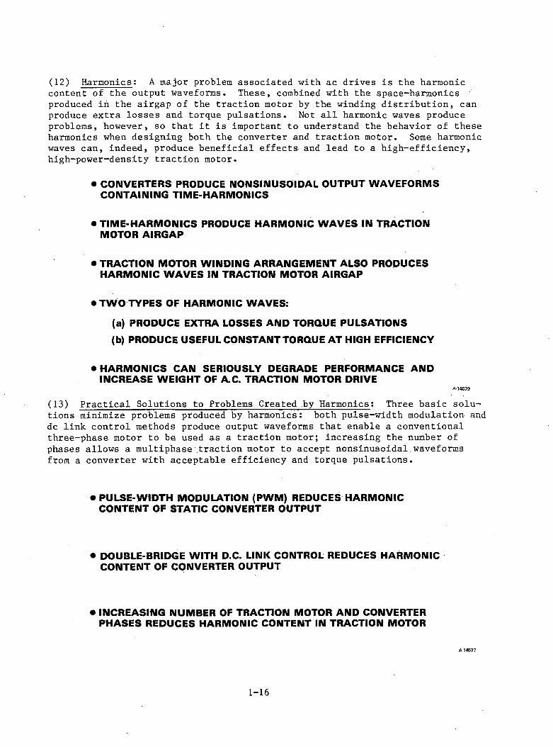
(12) Harmonics: A major problem associated with ac drives is the harmoniccontent of the output waveforms. These, combined with the space-harmonics produced in the airgap of the traction motor by the winding distribution, can produce extra losses and torque pulsations. Not a l l harmonic waves produce problems, however, so that i t is important to understand the behavior of these harmonics when designing both the converter and traction motor. Some harmonic waves can, indeed, produce beneficial effects and lead to a high-efficiency, high-power-density traction motor.
• CONVERTERS PRODUCE NONSINUSOIDAL OUTPUT WAVEFORMS CONTAINING TIME-HARMONICS
• TIME-HARMONICS PRODUCE HARMONIC WAVES IN TRACTION MOTOR AIRGAP
• TRACTION MOTOR WINDING ARRANGEMENT ALSO PRODUCES HARMONIC WAVES IN TRACTION MOTOR AIRGAP
• TWO TYPES OF HARMONIC WAVES:
(a) PRODUCE EXTRA LOSSES AND TORQUE PULSATIONS(b) PRODUCE USEFUL CONSTANT TORQUE AT HIGH EFFICIENCY
• HARMONICS CAN SERIOUSLY DEGRADE PERFORMANCE AND INCREASE WEIGHT OF A.C. TRACTION MOTOR DRIVE
A-14579
(13) P ractical Solutions to Problems Created by Harmonics: Three basic solutions minimize problems produced by harmonics: both pulse-width modulation anddc link control methods produce output waveforms that enable a conventional three-phase motor to be used as a traction motor; increasing the number of phases allows a multiphase traction motor to accept nonsinusoidal waveforms from a converter with acceptable efficiency and torque pulsations.
• PULSE-WIDTH MODULATION (PWM) REDUCES HARMONIC CONTENT OF STATIC CONVERTER OUTPUT
• DOUBLE-BRIDGE WITH D.C. LINK CONTROL REDUCES HARMONIC CONTENT OF CONVERTER OUTPUT
• INCREASING NUMBER OF TRACTION MOTOR AND CONVERTER PHASES REDUCES HARMONIC CONTENT IN TRACTION MOTOR
A-14577
1-16
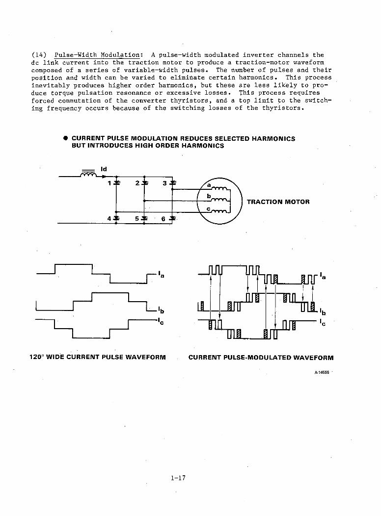
(14) Pulse-Width Modulation; A pulse-width modulated inverter channels the dc link current into the traction motor to produce a traction-motor waveform composed of a series of variable-width pulses. The number of pulses and their position and width can be varied to eliminate certain harmonics. This process inevitably produces higher order harmonics, but these are less lik ely to produce torque pulsation resonance or excessive losses. This process requires forced commutation of the converter th yristors, and a top lim it to the switching frequency occurs because of the switching losses of the th y risto rs.
• C U R R E N T P U L S E M O D U L A T IO N R E D U C E S S E L E C T E D H A R M O N IC S B U T IN T R O D U C E S H IG H O R D E R H A R M O N IC S
120° WIDE CURRENT PULSE WAVEFORM CURRENT PULSE-MODULATED WAVEFORMfir 14555
1-17

waveforms can contain reduced harmonic content over a band of harmonics, but an increase in harmonics outside this band is likely to occur. The effect of this waveform on output torque variation is shown below. If carefully controlled, the modulated waveform can considerably reduce resonance torque pulsation during startin g .
(15) Wave f o r m Improvement wi t h Current Pulse M o d u l a t i o n : P u l s e-width mo d u l a t e d
1 1 i i ~ m uuY in _ n n r
120° WIDE CURRENT PULSE CURRENT PULSE MODULATION
•*— WAVEFORM — ►
•*— SPECTRUM— ►
1 I 1 1 I - J. 1 -L I 1 3 5 7 9 1113151719
A i ' i ■ ■1 3 5 7 9 1113 15 17 19
«*— TORQUE— ►
T
0T
0
A-14556
1-18
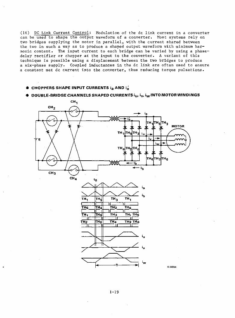
(16) DC Link Current Control: Modulation of the dc link current in a convertercan be used to shape the output waveform of a converter. Most systems rely on two bridges supplying the motor in p aralle l, with the current shared between the two in such a way as to produce a shaped output waveform with minimum harmonic content. The input current to each bridge can be varied by using a phase- delay r e c t if ie r or chopper at the input to the converter. A variant of this technique is possible using a displacement between the two bridges to produce a six-phase supply. Coupled inductances in the dc link are often used to ensure a constant net dc current into the converter, thus reducing torque pulsations.
• C H O P P E R S S H A P E IN P U T C U R R E N T S ia A N D ig
• D O U B L E - B R ID G E C H A N N E L S S H A P E D C U R R E N T S iu , iv , iw IN T O M O T O R W IN D IN G S
C H 1
/ " V
V /™«51 i t h3 TH1
i II II ITH6 THa TH2 th6| | II II IthJ TH3 THjTH5
n 1 1 II IITH2 th6' th4 TH2 TH6II II II
sA ____ X
y
\/
/\
x ___ T --^A-14S54
1-19
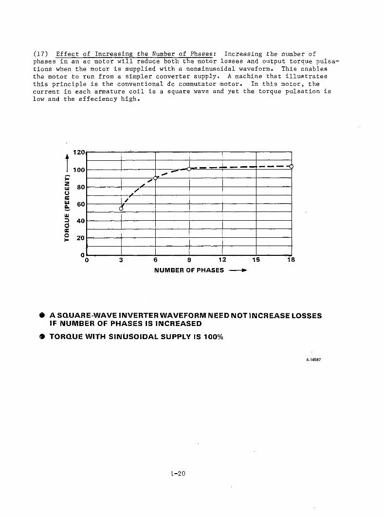
(17) Effect of Increasing the Number of Phases: Increasing the number ofphases in an ac motor w ill reduce both the motor losses and output torque pulsations when the motor is supplied with a nonsinusoidal waveform. This enables the motor to run from a simpler converter supply. A machine that illu s tra te s this principle is the conventional dc commutator motor. In this motor, the current in each armature co il is a square wave and yet the torque pulsation is low and the effeciency high.
n
HZUJOtcUJ(LUJ3dtco1-
N U M B E R O F P H A S E S -------►
• A SQUARE-WAVE INVERTER WAVEFORM NEED NOT INCREASE LOSSES IF NUMBER OF PHASES IS INCREASED
m TORQUE WITH SINUSOIDAL SUPPLY IS 100%
A-14567
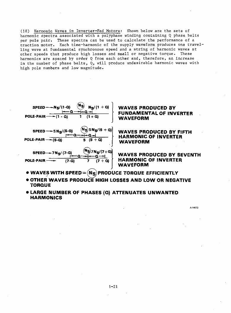
(18) Harmonic Waves in Inverter-Fed Motors: Shown below are the sets ofharmonic spectra associated with a polyphase winding containing Q phase belts per pole pair. These spectra can be used to calculate the performance of a traction motor. Each time-harmonic of the supply waveform produces one travel ling wave at fundamental synchronous speed and a string of harmonic waves at other speeds that produce high losses and small or negative torque. These harmonics are spaced by order Q from each other and, therefore, an increase in the number of phase belts, Q, will produce undesirable harmonic waves with high pole numbers and low magnitude.
S P E E D — - N s / ( 1 - Q ) N s / (1 + Q )h ^ Q — 4 * Q - H ________ •
P O L E -P A IR ----- — (1 - Q) 1 (1 + Q)
S P E E D — 5 IM s/(5 -Q ) (^ s ) 5 N s / (5 + Q}'______ l~*— Q — ■ I" Q — j_____ .
P O L E -P A IR — (5-Q ) 5 (5 + Q)
S P E E D — 7 N s / (7 -Q ) @ 7 N s /(7 + Q )__________ r — Q - - I - q - H
P O L E -P A IR -------- (7-Q) 7 (7 + Q)
W A V E S P R O D U C E D B Y F U N D A M E N T A L O F I N V E R T E R W A V E F O R M
W A V E S P R O D U C E D B Y FIFTH H A R M O N I C O F I N V E R T E R W A V E F O R M
W A V E S P R O D U C E D B Y S E V E N T H H A R M O N I C O F I N V E R T E R W A V E F O R M
• W A V E S W I T H S P E E D = (Ns) P R O D U C E T O R Q U E EFFICIENTLY• O T H E R W A V E S P R O D U C E H I G H L O S S E S A N D L O W O R N E G A T I V E T O R Q U E
• L A R G E N U M B E R O F P H A S E S (Q) A T T E N U A T E S U N W A N T E D H A R M O N I C S
A-14573
1-21
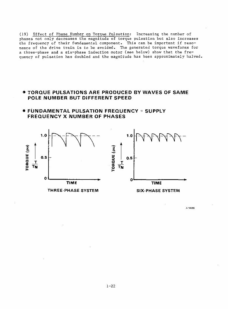
(19) Effect of Phase Number on Torque Pulsation: Increasing the number ofphases not only decreases the magnitude of torque pulsation but also increases the frequency of their fundamental component. This can be important if resonance of the drive train is to be avoided. The generated torque waveforms for a three-phase and a six-phase induction motor (see below) show that the frequency of pulsation has doubled and the magnitude has been approximately halved.
• T O R Q U E P U L S A T I O N S A R E P R O D U C E D B Y W A V E S O F S A M E P O L E N U M B E R B U T D S F F E R E N T S P E E D
® F U N D A M E N T A L P U L S A T I O N F R E Q U E N C Y = S U P P L Y F R E Q U E N C Y X N U M B E R O F P H A S E S
THREE-PHASE SYSTEM SIX-PHASE SYSTEM
A-14585
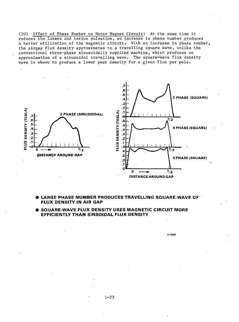
(20) Effect of Phase Number on Motor Magnet Circuit: At the same time itreduces the losses and torque pulsation, an increase in phase number produces a better utilization of the magnetic circuit. With an increase in phase number, the airgap flux density approximates to a travelling square wave, unlike the conventional three-phase sinusoidally supplied machine, which produces an approximation of a sinusoidal travelling wave. The square-wave flux density wave is shown to produce a lower peak density for a given flux per pole.
D IST A N C E A R O U N D G A P
• LARGE PHASE NUMBER PRODUCES TRAVELLING SQUARE-WAVE OF FLUX DENSITY IN AIR GAP
• SQUARE-WAVE FLUX DENSITY USES MAGNETIC CIRCUIT MORE EFFICIENTLY THAN SINSOIDAL FLUX DENSITY
A-14569
1-23
candidate drive systems will be considered separately, with particular attention to the modifications required to comply with traction requirements.
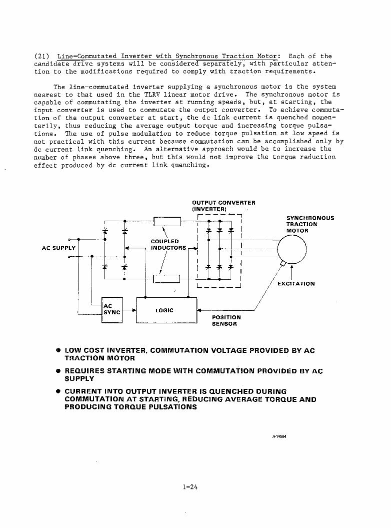
The line-commutated inverter supplying a synchronous motor is the system nearest to that used in the TLRV linear motor drive. The synchronous motor is capable of commutating the inverter at running speeds, but, at starting, the input converter is used to commutate the output converter. To achieve commutation of the output converter at start, the dc link current is quenched momentarily, thus reducing the average output torque and increasing torque pulsations. The use of pulse modulation to reduce torque pulsation at low speed is not practical with this current because commutation can be accomplished only by dc current link quenching. An alternative approach would be to increase the number of phases above three, but this would not improve the torque reduction effect produced by dc current link quenching.
(21) L i n e - C o m m u t a t e d Inverter with Synchronous Traction M o t o r : Eac h of the
OUTPUT CONVERTER (INVERTER)
« LOW COST INVERTER, COMMUTATION VOLTAGE PROVIDED BY AC TRACTION MOTOR
• REQUIRES STARTING MODE WITH COMMUTATION PROVIDED BY AC SUPPLY
• CURRENT INTO OUTPUT INVERTER IS QUENCHED DURING COMMUTATION AT STARTING, REDUCING AVERAGE TORQUE AND PRODUCING TORQUE PULSATIONS
A-14564
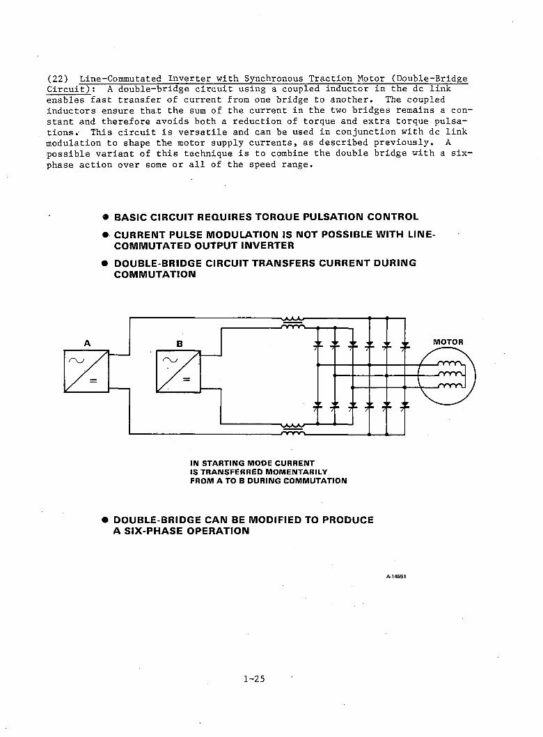
(22) Line-Commutated Inverter with Synchronous Traction Motor (Double-Bridge Circuit): A double-bridge circuit using a coupled inductor in the dc linkenables fast transfer of current from one bridge to another. The coupled inductors ensure that the sum of the current in the two bridges remains a constant and therefore avoids both a reduction of torque and extra torque pulsations.- This circuit is versatile and can be used in conjunction with dc link modulation to shape the motor supply currents, as described previously. A possible variant of this technique is to combine the double bridge with a six- phase action over some or all of the speed range.
• BASIC CIRCUIT REQUIRES TORQUE PULSATION CONTROL• CURRENT PULSE MODULATION IS NOT POSSIBLE WITH LINE-
COMMUTATED OUTPUT INVERTER• DOUBLE-BRIDGE CIRCUIT TRANSFERS CURRENT DURING
COMMUTATION
IN STARTING MODE CURRENT IS TRANSFERRED MOMENTARILY FROM A TO B DURING COMMUTATION
• DOUBLE-BRIDGE CAN BE MODIFIED TO PRODUCE A SIX-PHASE OPERATION
A-14551
1-25

(23) Improvement of Wayside Supply Power Factor: A line-commutated input converter suffers from a low input power factor at low-output de voltage. This can be improved by using a self-commutated converter, as shown. An improvement in the input harmonic content can be achieved by a further modification to the input converter: using a tapped supply transformer and a further self-commutatedarm to the input converter.
Id Ld
A-14552
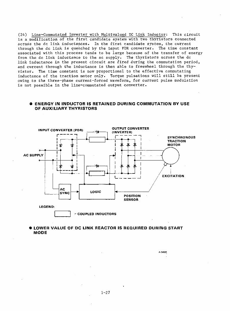
(24) Line-Commutated Inverter with Multivalued DC Link Inductor: This circuitis a modification of the first candidate system with two thyristors connected across the dc link inductances. In the first candidate system, the current through the dc link is quenched by the input PDR converter. The time constant associated with this process tends to be large because of the transfer of energy from the dc link inductance to the ac supply. The thyristors across the dc link inductance in the present circuit are fired during the commutation period, and current through the inductance is then able to freewheel through the thyristor. The time constant is now proportional to the effective commutating inductance of the traction motor only. Torque pulsations will still be present owing to the three-phase current-forced waveform, for current pulse modulation is not possible in the line-commutated output converter.
• ENERGY IN INDUCTOR IS RETAINED DURING COMMUTATION BY USE OF AUXILIARY THYRISTORS
LEGEND:= COUPLED INDUCTORS
• LOWER VALUE OF DC LINK REACTOR IS REQUIRED DURING START MODE
A-14562
1 - 2 7
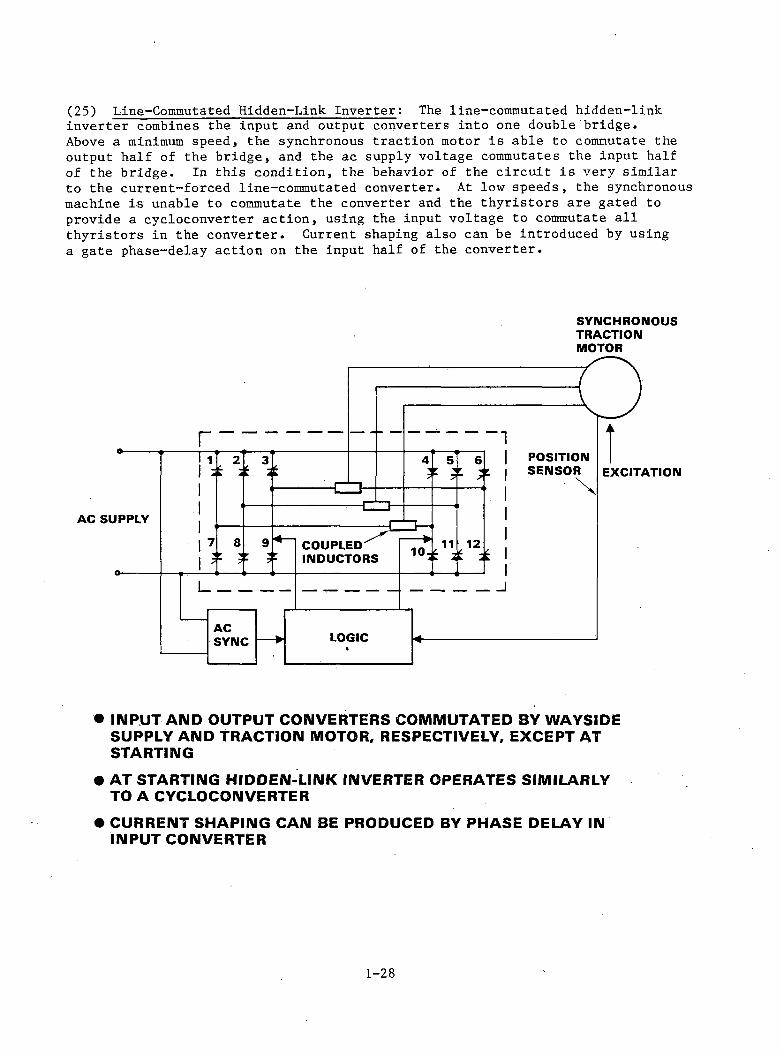
(25) Line-Commutated Hidden-Link Inverter: The line-commutated hidden-linkinverter combines the input and output converters into one double bridge.Above a minimum speed, the synchronous traction motor is able to commutate the output half of the bridge, and the ac supply voltage commutates the input half of the bridge. In this condition, the behavior of the circuit is very similar to the current-forced line-commutated converter. At low speeds, the synchronous machine is unable to commutate the converter and the thyristors are gated to provide a cycloconverter action, using the input voltage to commutate all thyristors in the converter. Current shaping also can be introduced by using a gate phase-delay action on the input half of the converter.
SYNCHRONOUSTRACTIONMOTOR
• INPUT AND OUTPUT CONVERTERS COMMUTATED BY WAYSIDE SUPPLY AND TRACTION MOTOR, RESPECTIVELY, EXCEPT AT STARTING
• AT STARTING HIDDEN-LINK INVERTER OPERATES SIMILARLY TO A CYCLOCONVERTER
• CURRENT SHAPING CAN BE PRODUCED BY PHASE DELAY IN INPUT CONVERTER
1 - 2 8

(26) Capacitor-Assisted Hidden-Link Inverter: Capacitor-assisted commutationcan be used in a hidden-link circuit to provide a self-commutated converter capable of supplying either an induction or a synchronous traction motor. The self-commutated hidden-link converter is also capable of pulse modulation, which can be used to reduce torque pulsation in the traction motor.
• C A P A C IT O R C O M M U TA TIO N O F IN P U T A N D O U TP U T S E C T IO N S
• C O M P A T IB L E W ITH A C IN D U C T IO N T R A C T IO N M O TO R
A-14593
1 - 2 9
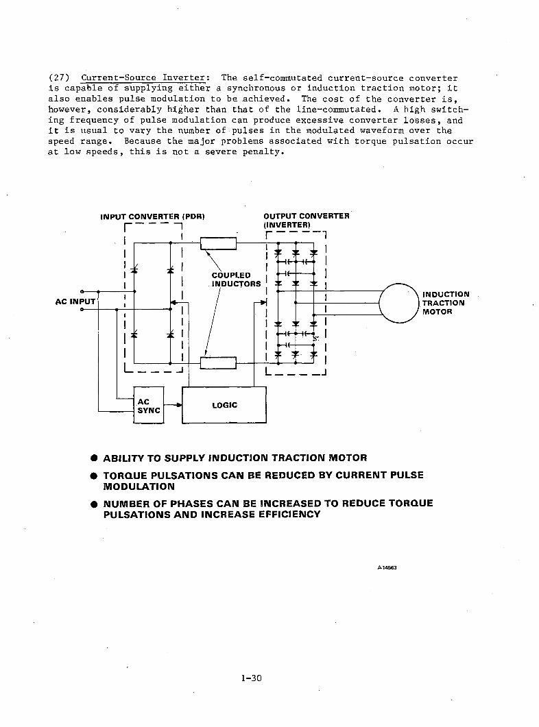
(27) Current-Source Inverter: The self-commutated current-source converteris capable of supplying either a synchronous or induction traction motor; it also enables pulse modulation to be achieved. The cost of the converter is, however, considerably higher than that of the line-commutated. A high switching frequency of pulse modulation can produce excessive converter losses, and it is usual to vary the number of pulses in the modulated waveform over the speed range. Because the major problems associated with torque pulsation occur at low speeds, this is not a severe penalty.
INPUT CONVERTER (PDR) OUTPUT CONVERTER
INDUCTIONTRACTIONMOTOR
• ABILITY TO SUPPLY INDUCTION TRACTION MOTOR• TORQUE PULSATIONS CAN BE REDUCED BY CURRENT PULSE
MODULATION• NUMBER OF PHASES CAN BE INCREASED TO REDUCE TORQUE
PULSATIONS AND INCREASE EFFICIENCY
£-14 5 6 3
1 - 3 0

(28) Six-Phase Current-Source Inverter: The current-source converter can beused to provide any number of output phases. A convenient system consists of two 3-phase converters supplying a six-phase traction motor, with one of the converters phase-displaced by 30 deg with respect to the other. The increase in phase number not only decreases the torque pulsations produced by the motor, but also increases the efficiency. Much of the reduction in loss occurs in the rotor owing to the reduction of high velocity harmonic waves in the airgap of the motor.
• TW O H A L F - R A T E D T H R E E - P H A S E IN V E R T E R S D IS P L A C E D B Y 3 0 °
• R O T O R C O P P E R L O S S E S A R E R E D U C E D
A-14557
1 - 3 1
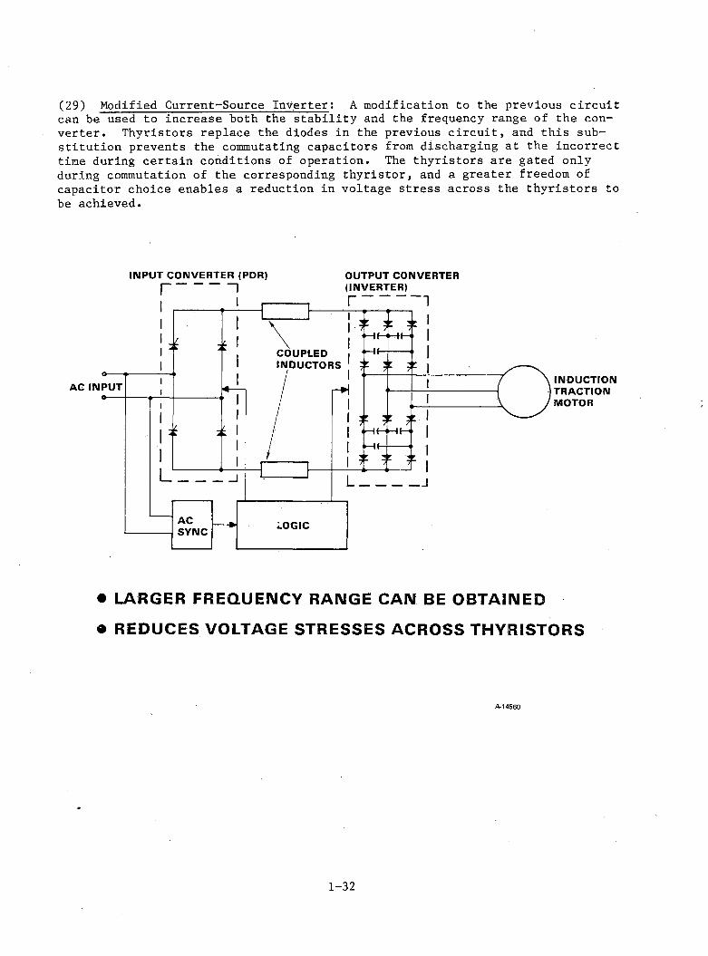
(29) Modified Current-Source Inverter: A modification to the previous circuitcan be used to increase both the stability and the frequency range of the converter. Thyristors replace the diodes in the previous circuit, and this substitution prevents the commutating capacitors from discharging at the incorrect time during certain conditions of operation. The thyristors are gated only during commutation of the corresponding thyristor, and a greater freedom of capacitor choice enables a reduction in voltage stress across the thyristors to be achieved.
INPUT CONVERTER (PDR) OUTPUT CONVERTER
• L A R G E R F R E Q U E N C Y R A N G E C A N B E O B T A IN E D
• R E D U C E S V O L T A G E S T R E S S E S A C R O S S T H Y R IS T O R S
A-14560
1 - 3 2
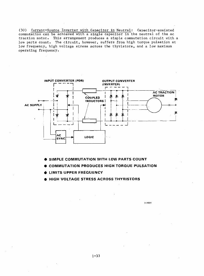
(30) Current-Source Inverter with Capacitor in Neutral: Capacitor-assistedcommutation can be achieved with a single capacitor in the neutral of the ac traction motor. This arrangement produces a simple commutation circuit with a low parts count. The circuit, however, suffers from high torque pulsation at low frequency, high voltage stress across the thyristors, and a low maximum operating frequency.
INPUT CONVERTER (PDR) OUTPUT CONVERTERf | (INVERTER)
• SIMPLE COMMUTATION WITH LOW PARTS COUNT• COMMUTATION PRODUCES HIGH TORQUE PULSATION• LIMITS UPPER FREQUENCY• HIGH VOLTAGE STRESS ACROSS THYRISTORS
A -14591
1-33

(31) Control Circuit Requirements: The control circuit must perform severalfunctions to ensure correct operation of the locomotive. The timing of the gate signals to the power conditioner must first ensure that the traction motor is not overloaded electrically, magnetically, or thermally. It must also minimize torque pulsations and optimize the power factor and efficiency of the system over the speed range. An efficient control of axle slip is also required to maximize drawbar pull.
• CONTROL EACH AXLE TORQUE TO SHARE LOAD AND LIMIT SLIP
• CONTROL FLUX AND CURRENT LEVELS IN TRACTION MOTORS
• CONTROL TORQUE PULSATIONS
• USE CURRENT PULSE MODULATION
• SELECT NUMBER OF PULSE PER CYCLE
• CONTROL FIRING ANGLE FOR POWER FACTOR OPTIMIZATION AND COMMUTATION FAILURE PREVENTION
• CONTROL START-TO-RUN MODE TRANSFER A-14590
(32) Thyristor Module: The TLRV power conditioner was constructed using thyristor modules. Each module contains two water-cooled thyristors, a protection circuit, and a gate firing circuit. The modules can be reconnected to produce the required converter, using a microprocessor circuit to provide correct gate timing. Because water cooling can produce maintenance problems associated with the risk of contamination, the possibility of oil cooling has been investigated.
F -3 5 61 3
1 - 3 4
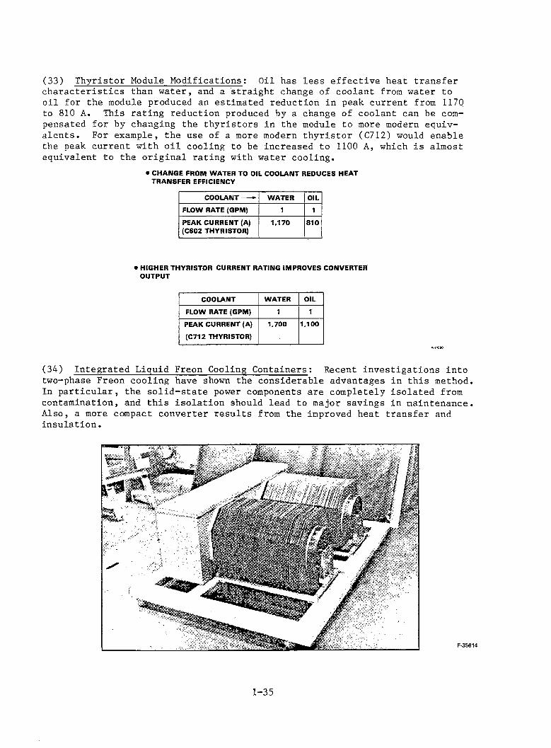
(33) Thyristor Module Modifications; Oil has less effective heat transfer characteristics than water, and a straight change of coolant from water to oil for the module produced an estimated reduction in peak current from 1170 to 810 A. This rating reduction produced by a change of coolant can be compensated for by changing the thyristors in the module to more modern equivalents. For example, the use of a more modern thyristor (C712) would enable the peak current with oil cooling to be increased to 1100 A, which is almost equivalent to the original rating with water cooling.
• CHANGE FROM WATER TO OIL COOLANT REDUCES HEAT TRANSFER EFFICIENCYCOOLANT-► WATER OIL
FLOW RATE (GPM) 1 1PEAK CURRENT (A) (C602 THYRISTOR) 1,170 810
• HIGHER THYRISTOR CURRENT RATING IMPROVES CONVERTER OUTPUTCOOLANT WATER OIL
FLOW RATE (GPM) 1 1PEAK CURRENT (A) (C712 THYRISTOR)
1,700 1,100
(34) Integrated Liquid Freon Cooling Containers: Recent investigations intotwo-phase Freon cooling have shown the considerable advantages in this method. In particular, the solid-state power components are completely isolated from contamination, and this isolation should lead to major savings in maintenance. Also, a more compact converter results from the improved heat transfer and insulation.
1 - 3 5
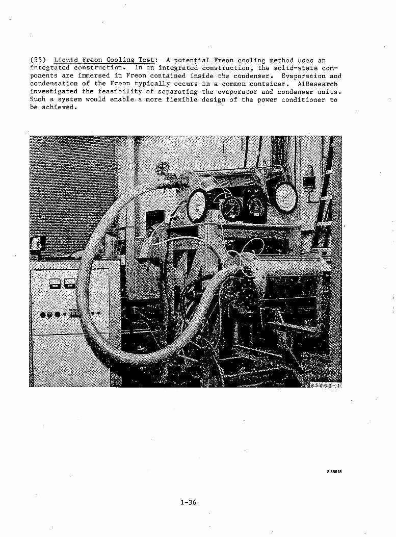
(35) Liquid Freon Cooling Test: A potential Freon cooling method uses anintegrated construction. In an integrated construction, the solid-state components are immersed in Freon contained inside the condenser. Evaporation and condensation of the Freon typically occurs in a common container. AiEesearch investigated the feasibility of separating the evaporator and condenser units. Such a system would enable a more flexible design of the power conditioner to be achieved.
F -3 5 61 5
1 - 3 6
(1) Converter and Traction Motor Construction: This study has compared thealternative inverter/motor combinations that can be developed for traction R&D from the TLRV hardware. A limited study such as this cannot predict realistically such important design features as interaction of motor and track, detailed constructional layout, nonlinear effects, and cross-coupling control and pickup problems. It is therefore desirable that a full-scale two-axle (1.5 MW/axle) drive be designed, constructed, and tested. Such a drive should be capable of being reconnected to produce all the preferred candidate systems discussed herein. This modular universal inverter drive system, using a microprocessor gate firing control, should be constructed after an initial design phase. This system, with reprogramming of the microprocessor and minimum reconnection, will be capable of operating in any of the bridge formations described in Sections 2 and 3, including three-phase and six-phase operation. Both induction—type and synchronous-type traction motors should be investigated. Either extra terminal connections or simple internal reconnection will enable these machines to be converted easily from three phase to six phase for both types of motors. The converter unit should be constructed in skid form to enable both dynamometer and field tests to be performed.
The thyristor module arrangement requires careful design consideration if it is to function in all the possible operating modes. The most important of these considerations are:
(a) Inverter grade thyristors will be required for the self-commutated bridge operation and they will therefore be overdesigned for the line-commutated versions.
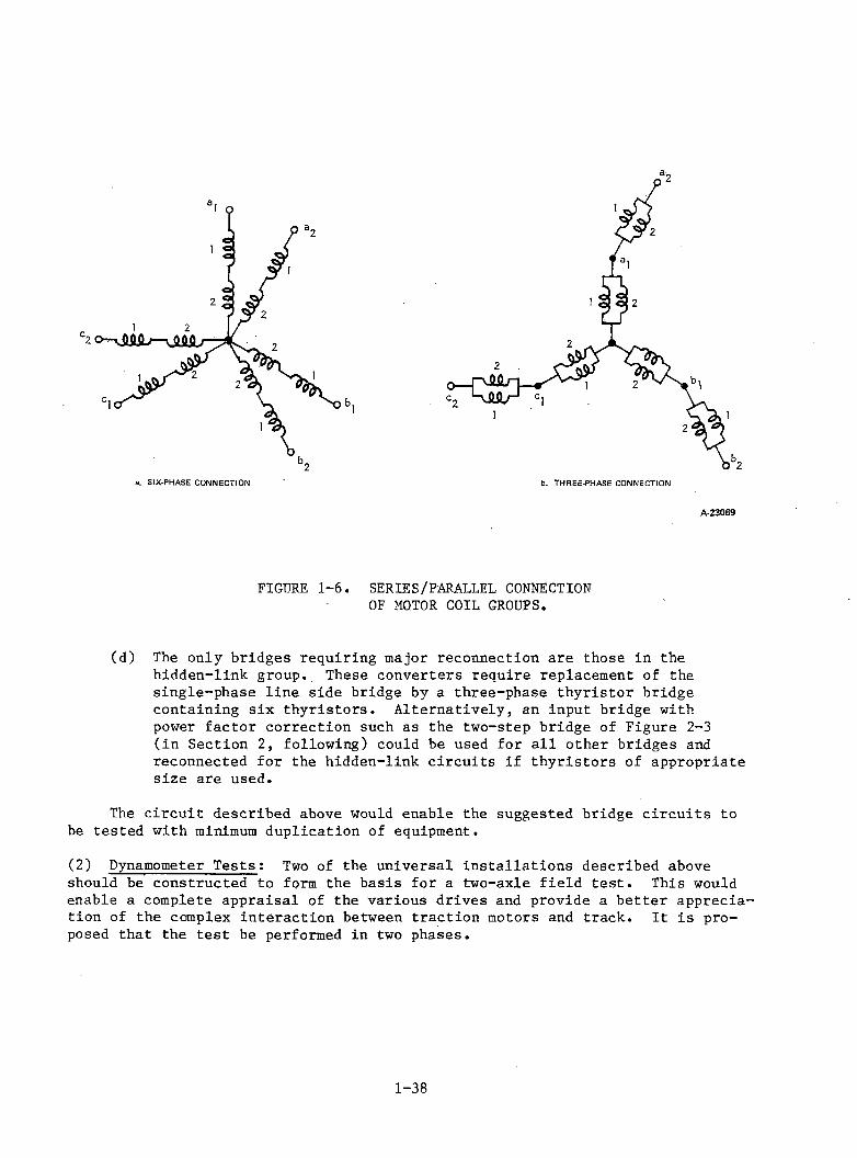
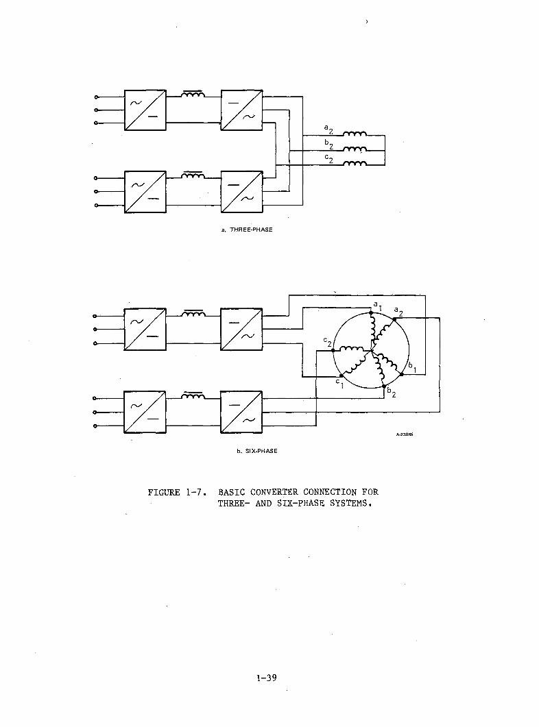
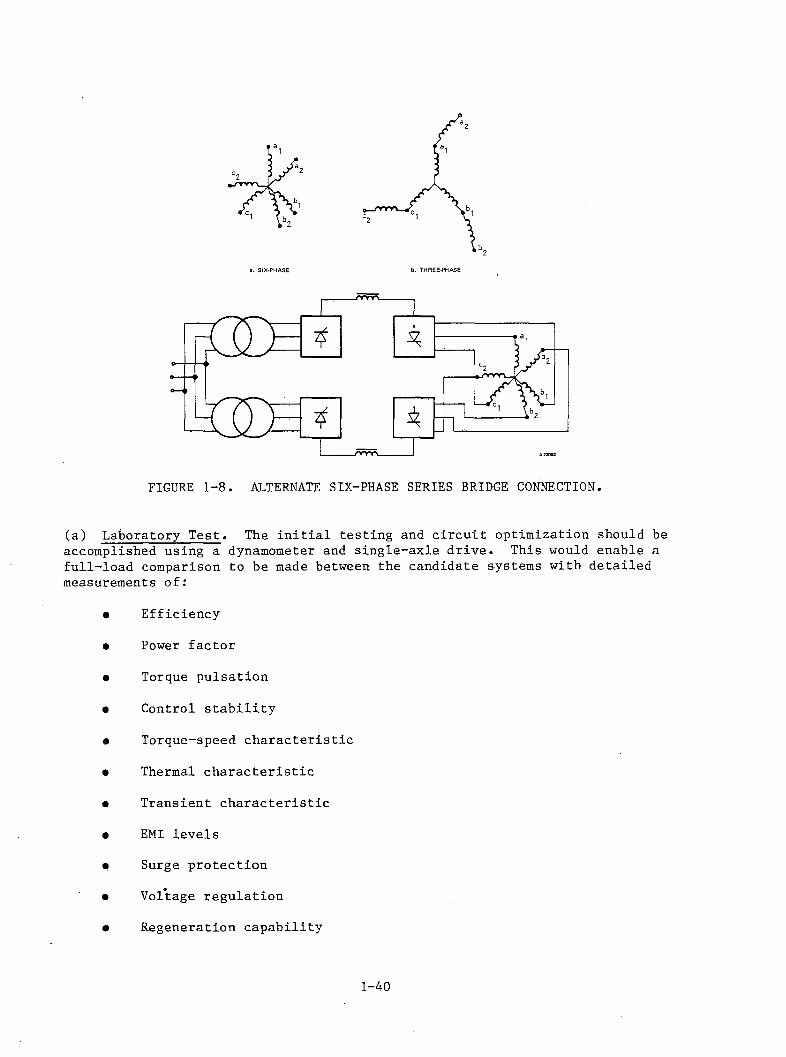
(b) Although it is possible to transfer from six-phase to three-phase operation without motor coil reconnection, it is better from a bridge voltage stress point of view to reconnect the motor as shown in Figure 1-6. The reconnection of the 1 and 2 coil groupsto a series connection in the motor must be accompanied by a series/ parallel coil reconnection to keep the bridge voltage levels approximately the same for both three- and six-phase connections. Figure 1-7 shows the basic converter connection for the three- and six- phase systems. An alternative to this method that avoids the series parallel reconnection in the motor is to connect the bridges in series for the six-phase condition as shown in Figure 1-8. This arrangement results in a higher voltage stress in both motor and converter.
(c) The self-commutated bridges require either extra diodes or thyristors . to avoid capacitor discharge between commutation; These can beeither permanently connected during operation of all bridge configurations or bypassed for the line-commutated converters. Capacitors will have to be disconnected in line-commutated bridges.
c. Recommendations for Future Research and Development.
1 - 3 7
A-23069
FIGURE 1-6. SERIES/PARALLEL CONNECTION OF MOTOR COIL GROUPS.
(d) The only bridges requiring major reconnection are those in the hidden-link group. These converters require replacement of the single-phase line side bridge by a three-phase thyristor bridge containing six thyristors. Alternatively, an input bridge with power factor correction such as the two-step bridge of Figure 2-3 (in Section 2, following) could be used for all other bridges and reconnected for the hidden-link circuits if thyristors of appropriate size are used.
The circuit described above would enable the suggested bridge circuits to be tested with minimum duplication of equipment.
(2) Dynamometer Tests: Two of the universal installations described aboveshould be constructed to form the basis for a two-axle field test. This would enable a complete appraisal of the various drives and provide a better appreciation of the complex interaction between traction motors and track. It is proposed that the test be performed in two phases.
1 - 3 8
>
b. SIX-PHASE
FIGURE 1-7. BASIC CONVERTER CONNECTION FOR THREE- AND SIX-PHASE SYSTEMS.
1 - 3 9
'2
FIGURE 1-8. ALTERNATE SIX-PHASE SERIES BRIDGE CONNECTION.
(a) Laboratory Test. The initial testing and circuit optimization should be accomplished using a dynamometer and single-axle drive. This would enable a full-load comparison to be made between the candidate systems with detailed measurements of:
• Efficiency
• Power factor
• Torque pulsation
• Control stability
• Torque-speed characteristic
• Thermal characteristic
• Transient characteristic
• EMI levelsSurge protection
Voltage regulation
Regeneration capability
1 - 4 0
The dynamometer control should be microprocessor controlled to simulate conditions such as wheelslip and rail distortion. To fully measure the complex interaction between traction motor and rail, however, it will be necessary to complete the system tests on a dynamic rail simulator.
(b) Rail Simulator Test and Field Test. The FRA Dynamic Rail Simulator at the Transportation Test Center in Pueblo, Colorado, is capable of measuring the performance of a complete two-axle truck more realistically than could be achieved on a laboratory dynamometer set. For this test, one truck with associated two-axle converter and controls would be constructed, using the motors and equipment developed and improved during the laboratory dynamometer test.
Finally, the complete performance and dynamic control of the optimized circuits can be measured and compared to select the optimum traction drive for the American railroad conditions. The results of these simulator tests should ensure the right choice of.a system for the final series of field tests.
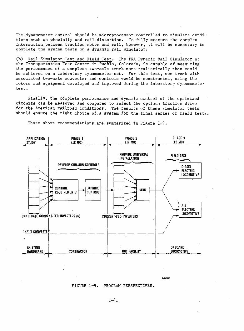
These above recommendations are summarized in Figure 1-9.
A-14553
FIGURE 1-9. PROGRAM PERSPECTIVES.
1 - 4 1
REFERENCESGuarino, M., "The Planning of Research and Development of Electrical Traction for Railroads in the Light of the Energy Shortage," IEEE/ ASME/AAR Joint Railroad Conference, April 1981.
Roberts, R., "Wanted: Million-mile Locomotive," Modern Railroads,Vol. 35, No. 10, 1980, pp. 42-45.
Kielgas, H., "Converter Propulsion Systems with Three-Phase Induction Motors for Electric Traction Vehicles," IEE/IAS International Semiconductor Power Converter Conference, 1977, pp. 305-319.
Kalman, G., "Linear Motors Power DOT's High-Speed Research Vehicles," Railway Gazette International, Vol. 130, No. 10, 1974, pp. 378-383.
.____________ , "Experimental Locos Feature 1000 kW Motors WithoutCommutators," Railway Gazette International, Vol, 133, No. 7, 1977,pp. 260-261.
Ward, E., "Invertor Suitable for Operation over a Range of Frequency," Proceedings of the IEEE, Vol. Ill, No. 8, 1964, pp. 1423-1434.
Joshi, A., "Modified Current Source Inverter for Squirrel Cage Motor Drive," IEEE Transactions on Magnetics, Vol. MAG-14, No. 5, 1978, pp. 930-932.
Adamson, C., and H. Hingorani, High Voltage Direct Current Transmission, London: Ganaway Ltd., 1960, Chapter 8, pp. 121-132.
Steigerwald, R., "Characteristics of a Current-Fed Inverter with Commutation Applied Through the Load Neutral Point," IEEE/IAS Annual Meeting, 1978, pp. 502-509.
1-42
PART II
TECHNICAL DISCUSSION
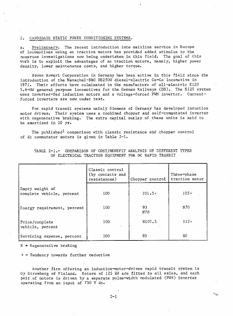
a. Preliminary. The recent introduction into mainline service in Europe of locomotives using ac traction motors has provided added stimulus to the numerous investigations now being undertaken in this field. The goal of this work is to exploit the advantages of ac traction motors, namely, higher power density, lower maintenance costs, and higher torque.
Brown Boveri Corporation in Germany has been active in this field since the introduction of the Henschel-BBC DE2500 diesel-electric Co-Co locomotive in 1971. Their efforts have culminated in the manufacture of all-electric E120 5.6-MW'general purpose locomotives for the German Railways (DB). The E120 system uses inverter-fed induction motors and a voltage-forced PWM inverter. Current- forced inverters are now under test.
For rapid transit systems mainly Siemens of Germany has developed induction motor drives. Their system uses a combined chopper and self-commutated inverter with regenerative braking. The extra capital outlay of these units is said to be amortized in 10 yr.
The published-*- comparison with classic resistance and chopper control of dc commutator motors is given in Table 2-1.
2. CANDIDATE STATIC POWER CONDITIONING SYSTEMS.
TABLE 2-1.- COMPARISON OF COST/BENEFIT ANALYSIS OF DIFFERENT TYPES OF ELECTRICAL TRACTION EQUIPMENT FOR DC RAPID TRANSIT
Classic control (by contacts and resistances) Chopper control
Three-phase traction motor
Empty, weight of complete vehicle, percent 100 101.54 103 +
Energy requirement, percent 100 93N70
N70
Price/complete vehicle, percent
100 N107.5 1124
Servicing expense, percent 100 85 80
N = Regenerative braking
1 = Tendency towards further reduction
Another firm offering an induction-motor-driven rapid transit system is Oy Stromberg of Finland. Rotors of 125 kW are fitted to all axles, and each pair of motors is driven by a separate pulse-width modulated (PWM) inverter operating from an input of 750 V dc.
2 - 1
Experimental work by S.N.C.F. in France is well along, with trials of both induction-motor and synchronous-motor systems imminent. A 5-MW four-axle locomotive with three-phase induction traction motors and separate self-commutated inverters for each axle will enable either separate control of each axle or paralleling of motors. An interesting feature of this locomotive is its two- phase liquid cooling for the power semiconductors. S.N.C.F. is also building a research locomotive using synchronous traction motors. The inverter is machine-commutated at speeds above 5 percent of the maximum and uses a special starting commutation technique below this speed. This experimental locomotive, known as the BB 15000, is due to be tested at the end of 1981.
The British Rail Research Center, in conjunction with G.E.C., is engaged in dynamometer appraisal of induction traction motor drive systems, including a novel axle motor designed to fit inside the axle of the British Rail Advanced Passenger Train.
Although at present the majority of locomotive drives still retain dc commutator traction motors to take advantage of their lower initial cost, the continued rate of reduction in the cost of power semiconductors, combined with a demand for higher performance, is resulting in the introduction of several ac traction motor drives and considerable research activity in static power conditioning by major European manufacturers.
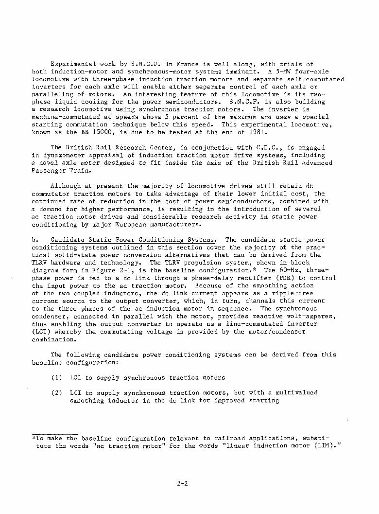
b. Candidate Static Power Conditioning Systems. The candidate static power conditioning systems outlined in this section cover the majority of the practical solid-state power conversion alternatives that can be derived from the TLRV hardware and technology. The TLRV propulsion system, shown in block diagram form in Figure 2-1, is the baseline configuration.* The 60-Hz, three- phase power is fed to a dc link through a phase-delay rectifier (PDR) to control the input power to the ac traction motor. Because of the smoothing action of the two coupled inductors, the dc link current appears as a ripple-free current source to the output converter, which, in turn, channels this current to the three phases of the ac induction motor in sequence. The synchronous condenser, connected in parallel with the motor, provides reactive volt-amperes, thus enabling the output converter to operate as a line-commutated inverter (LCI) whereby the commutating voltage is provided by the motor/condenser combination.
The following candidate power conditioning systems can be derived from this baseline configuration:
(1) LCI to supply synchronous traction motors
(2) LCI to supply synchronous traction motors, but with a multivalued smoothing inductor in the dc link for improved starting
*To make the baseline configuration relevant to railroad applications, substitute the words "ac traction motor" for the words "linear induction motor (LIM)."
2 - 2
SHOWN ARE EXISTING HARDWARE FROM TLRV-LIMPS PROGRAMS-89600 -B
FIGURE 2-1. BASELINE CONFIGURATION.
(3) Hidden dc link converter to operate with synchronous traction motors or asynchronous traction motors
(4) Capacitor-assisted current-source inverter (CSI) with series blocking diodes to supply synchronous or asynchronous traction motors
(5) Capacitor-assisted CSI with series blocking thyristors rather than blocking diodes to supply synchronous or asynchronous traction motors
(6) Capacitor-assisted CSI to supply synchronous or asynchronous traction motors, as above, but with the commutating capacitors concentratedin the neutral circuit
These six candidate systems are compared in terms of performance and cost. In comparing performance, the following factors are taken into account:
• Capability to produce a high starting torque
• Torque pulsations produced by motor and their effects on the mechanical transmission train •
• Ability of drive system to accommodate different wheel diameters
2 - 3
• Ability of drive system to control wheelslip
• Ability of drive system to regenerate during braking
• Efficiency of drive
• Power factor of drive
In the following paragraphs the advantages and disadvantages of each of these power conditioning unit (PCU) configurations will be discussed separately.
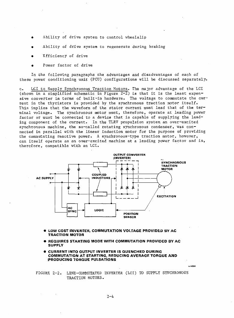
c. LCI to Supply Synchronous Traction Motors. The major advantage of the LCI (shown in a simplified schematic in Figure 2-2) is that it is the least expensive converter in terms of built-in hardware. The voltage to commutate the current in the thyristors is provided by the synchronous traction motor itself.This implies that the waveform of the stator current must lead that of the terminal voltage. The synchronous motor must, therefore, operate at leading power factor or must be connected to a device that is capable of supplying the leading component of the current. In the TLRV propulsion system an over-excited synchronous machine, the so-called rotating synchronous condenser, was connected in parallel with the linear induction motor for the purpose of providing the commutating reactive power. A synchronous-type traction motor, however, can itself operate as an over-excited machine at a leading power factor and is, therefore, compatible with an LCI.
OUTPUT CONVERTER
• LOW COST INVERTER, COMMUTATION VOLTAGE PROVIDED BY AC TRACTION MOTOR
• REQUIRES STARTING MODE WITH COMMUTATION PROVIDED BY AC SUPPLY
• CURRENT INTO OUTPUT INVERTER IS QUENCHED DURING COMMUTATION AT STARTING, REDUCING AVERAGE TORQUE AND PRODUCING TORQUE PULSATIONS
A-14564
FIGURE 2-2. LINE-COMMUTATED INVERTER (LCI) TO SUPPLY SYNCHRONOUS TRACTION MOTORS.
2 - 4
The basic operation of an LCI in conjunction with a synchronous traction motor is described in Appendix B. Large industrial drives have employed this technique for several years. The popularity of such drives is due to their high efficiency over a wide speed range and their four-quandrant operating ability (i.e., motoring or regenerating in either direction). The LCI units are, typically, free of the many power constraints of the force-commutated-type inverters and, therefore, are less complex and less expensive.
Control of the inverter output can be effected by either a front-end PDR or chopper. Either of these units can control the dc link current. Figure 2-2 shows a PDR front-end converter commutated by the ac supply that can be used to transfer power into or out of the dc link by controlling the firing delay angle.
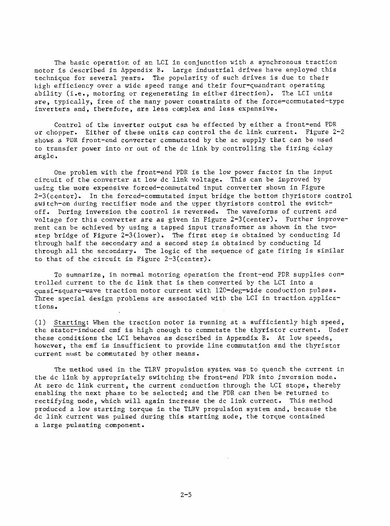
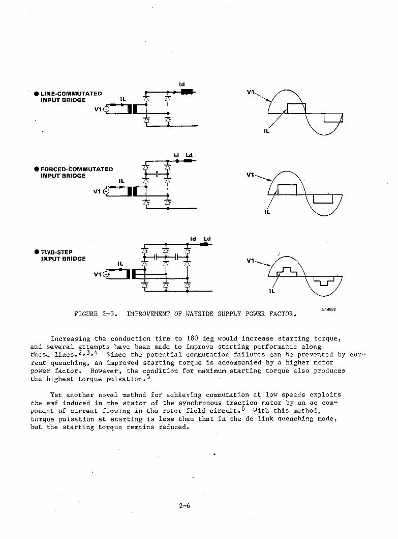
One problem with the front-end PDR is the low power factor in the input circuit of the converter at low dc link voltage. This can be improved by using the more expensive forced-commutated input converter shown in Figure 2-3(center). In the forced-commutated input bridge the bottom thyristors control switch-on during rectifier mode and the upper thyristors control the switch- off. During inversion the control is reversed. The waveforms of current and voltage for this converter are as given in Figure 2-3(center). Further improvement can be achieved by using a tapped input transformer as shown in the two- step bridge of Figure 2-3(lower). The first step is obtained by conducting Id through half the secondary and a second step is obtained by conducting Id through all the secondary. The logic of the sequence of gate firing is similar to that of the circuit in Figure 2-3(center).
To summarize, in normal mqtoring operation the front-end PDR supplies controlled current to the dc link that is then converted by the LCI into a quasi-square-wave traction motor current with 120-deg-wide conduction pulses. Three special design problems are associated with the LCI in traction applications .
(1) Starting; When the traction motor is running at a sufficiently high speed, the stator-induced emf is high enough to commutate the thyristor current. Under these conditions the LCI behaves as described in Appendix B. At low speeds, however, the emf is insufficient to provide line commutation and the thyristor current must be commutated by other means.
The method used in the TLRV propulsion system was to quench the current in the dc link by appropriately switching the front-end PDR into inversion mode.At zero dc link current, the current conduction through the LCI stops, thereby enabling the next phase to be selected; and the PDR can then be returned to rectifying mode, which will again increase the dc link current. This method produced a low starting torque in the TLRV propulsion system and, because the dc link current was pulsed during this starting mode, the torque contained a large pulsating component.
2-5
Id Ld
Id Ld
FIGURE 2-3. IMPROVEMENT OF WAYSIDE SUPPLY POWER FACTOR.
Increasing the conduction time to 180 deg would increase starting torque, and several attempts have been made to improve starting performance along these lines.2,3,4 Since the potential commutation failures can be prevented by current quenching, an improved starting torque is accompanied by a higher motor power factor. However, the condition for maximum starting torque also produces the highest torque pulsation.^
Yet another novel method for achieving commutation at low speeds exploits the emf induced in the stator of the synchronous traction motor by an ac component of current flowing in the rotor field circuit.^ With this method, torque pulsation at starting is less than that in the dc link quenching mode, but the starting torque remains reduced.
2 - 6
A different approach to the above starting methods is to use a double bridge. The input current to the motor is shared between bridges except during commutation, when current is transferred to one bridge via a coupled inductor, thus quenching the current in the other. An example of this circuit using a dc input that uses choppers and a duplex inverter as shown in Figure 2-4. At low frequencies this circuit uses the input chopper to commutate the inverter instead of an expensive forced-commutated inverter. Commutation takes place in the following steps:
(a) Current from the dotted half of the system (see Figure 2-4) is transferred to the solid half-system, so that the solid system now carries all the current and the dotted system carries zero current. This current transfer is accomplished by commutating off the main thyristor in one chopper while leaving the main thyristor in the other chopper conducting. This applies the dc input voltage as a source of commutation, causing the current transfer. The transfer is resisted only by the leakage inductance of the dc inductors; hence the need exists for tight coupling.
(b) Once the current in the dotted half-system has reached zero and the inverter thyristors have recovered their blocking state, a new pair of thyristors is selected and gated on.
(c) Now the dotted (zero current) chopper is phased up and the solid (twice-current) chopper is phased back a corresponding amount, so that the total current remains unchanged. The voltage difference between the two choppers plus any generated emf in the machine together drive the commutation of the current in the machine; commutation is resisted mostly by the machine leakage inductance. Commutation proceeds over many chopper cycles with the current increasing in the dotted system and decreasing in the solid system until the situation at the beginning of commutation is reversed and the dotted system is at twice current and the current in the solid system is zero.
(d) When the thyristors in the solid system inverter (now at zero current) have recovered their blocking state, a new thyristor pair is selected and gated on.
(e) The solid system is now in parallel with the dotted system and its current is raised rapidly to half-current value (the rate of transfer is limited only by the leakage inductance) while the total dc current is held steady. The commutation is now complete, and normal parallel operation is resumed, with each system carrying half the load until the next commutation is required.
2 - 7
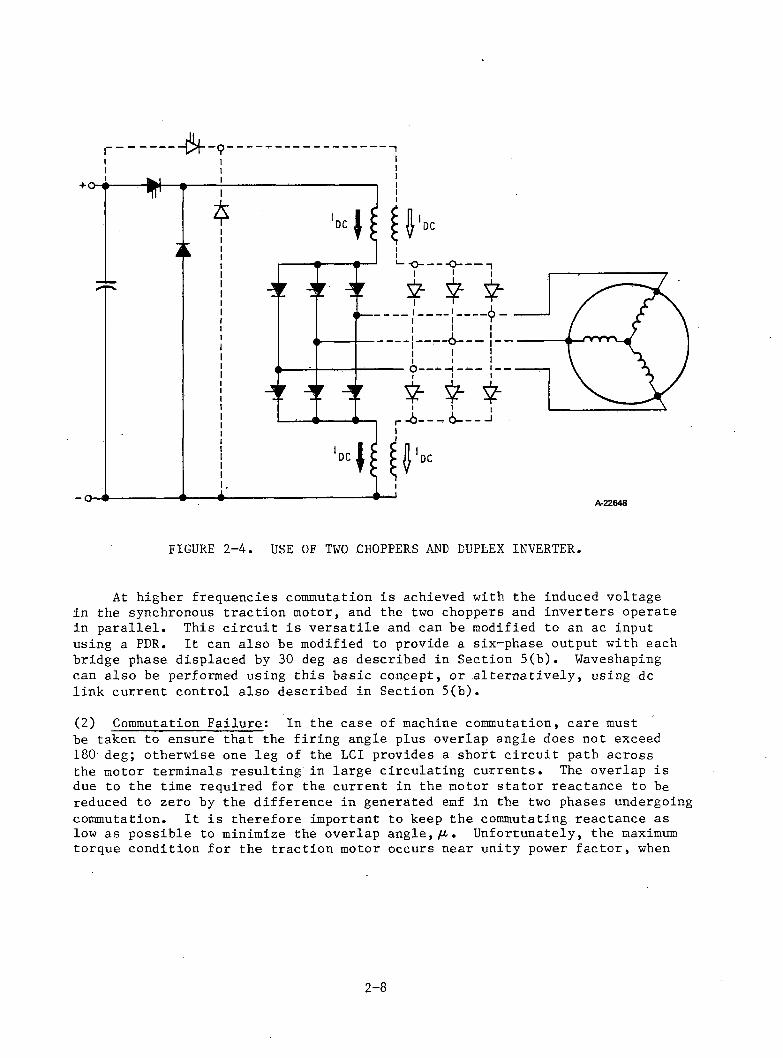
FIGURE 2-4. USE OF TWO CHOPPERS AND DUPLEX INVERTER.
At higher frequencies commutation is achieved with the induced voltage in the synchronous traction motor, and the two choppers and inverters operate in parallel. This circuit is versatile and can be modified to an ac input using a PDR. It can also be modified to provide a six-phase output with each bridge phase displaced by 30 deg as described in Section 5(b). Waveshaping can also be performed using this basic concept, or alternatively, using dc link current control also described in Section 5(b).
(2) Commutation Failure: In the case of machine commutation, care mustbe taken to ensure that the firing angle plus overlap angle does not exceed 180 deg; otherwise one leg of the LCI provides a short circuit path across the motor terminals resulting in large circulating currents. The overlap is due to the time required for the current in the motor stator reactance to be reduced to zero by the difference in generated emf in the two phases undergoing commutation. It is therefore important to keep the commutating reactance as low as possible to minimize the overlap angle,//.. Unfortunately, the maximum torque condition for the traction motor occurs near unity power factor, when
2-8
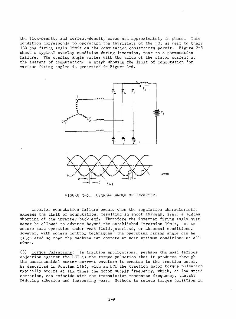
the flux-density and current-density waves are approximately in phase. This condition corresponds to operating the thyristors of the LCI as near to their 180-deg firing angle limit as the commutation constraints permit. Figure 2-5 shows a typical overlap condition during inversion, near to a commutation failure. The overlap angle varies with the value of the stator current at the instant of commutation. A graph showing the limit of commutation for various firing angles is presented in Figure 2-6.
A-22649
FIGURE 2-5. OVERLAP ANGLE OF INVERTER.
Inverter commutation failurev occurs when the regulation characteristic exceeds the limit of commutation, resulting in shoot-through, i.e., a sudden shorting of the inverter back emf. Therefore the inverter firing angle must never be allowed to advance beyond the established inversion limit, set to ensure safe operation under weak field, overload, or abnormal conditions. However, with modern control techniques^ the operating firing angle can be calculated so that the machine can operate at near optimum conditions at all times.
(3) Torque Pulsations: In traction applications, perhaps the most seriousobjection against the LCI is the torque pulsation that it produces through the nonsinusoidal stator current waveform it creates in the traction motor.As described in Section 5(b), with an LCI the traction motor torque pulsation typically occurs at six times the motor supply frequency, which, at low speed operation, can coincide with the transmission resonance frequency, thereby reducing adhesion and increasing wear. Methods to reduce torque pulsation in
2-9
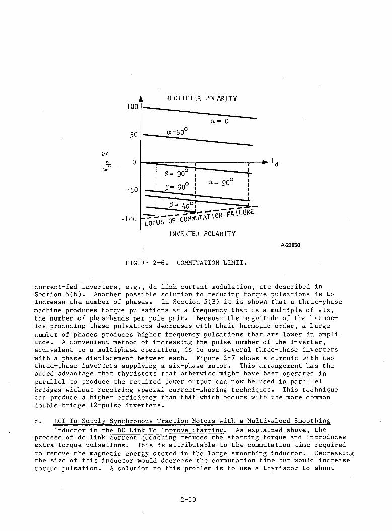
INVERTER POLARITYA-22650
FIGURE 2-6. COMMUTATION LIMIT.
current-fed inverters, e.g., dc link current modulation, are described in Section 5(b). Another possible solution to reducing torque pulsations is to increase the number of phases. In Section 5(B) it is shown that a three-phase machine produces torque pulsations at a frequency that is a multiple of six, the number of phasebands per pole pair. Because the magnitude of the harmonics producing these pulsations decreases with their harmonic order, a large number of phases produces higher frequency pulsations that are lower in amplitude. A convenient method of increasing the pulse number of the inverter, equivalent to a multiphase operation, is to use several three-phase inverters with a phase displacement between each. Figure 2-7 shows a circuit with two three-phase inverters supplying a six-phase motor. This arrangement has the added advantage that thyristors that otherwise might have been operated in parallel to produce the required power output can now be used in parallel bridges without requiring special current-sharing techniques. This technique can produce a higher efficiency than that which occurs with the more common double-bridge 12-pulse inverters.
d. LCI To Supply Synchronous Traction Motors with a Multivalued Smoothing Inductor in the DC Link To Improve Starting. As explained above, the
process of dc link current quenching reduces the starting torque and introduces extra torque pulsations. This is attributable to the commutation time required to remove the magnetic energy stored in the large smoothing inductor. Decreasing the size of this inductor would decrease the commutation time but would increase torque pulsation. A solution to this problem is to use a thyristor to shunt
2-10
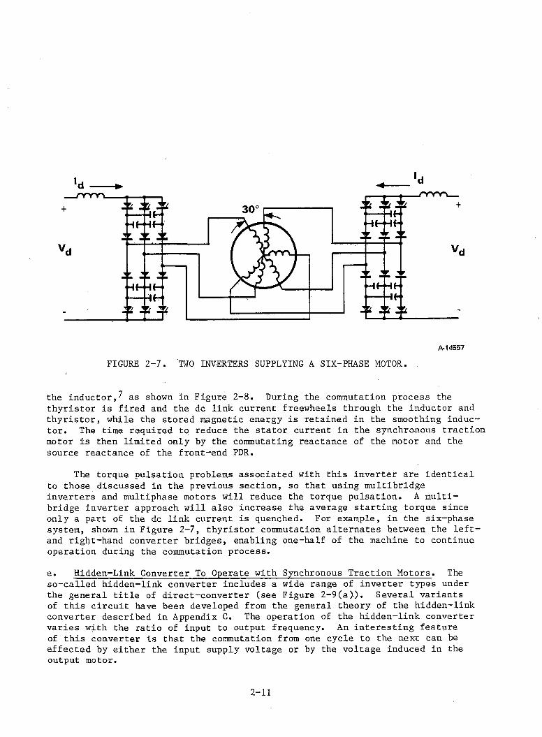
'd -----►
the inductor,^ as shown in Figure 2-8. During the commutation process the thyristor is fired and the dc link current freewheels through the inductor and thyristor, while the stored magnetic energy is retained in the smoothing inductor. The time required to reduce the stator current in the synchronous traction motor is then limited only by the commutating reactance of the motor and the source reactance of the front-end PDR.
The torque pulsation problems associated with this inverter are identical to those discussed in the previous section, so that using multibridge inverters and multiphase motors will reduce the torque pulsation. A multibridge inverter approach will also increase the average starting torque since only a part of the dc link current is quenched. For example, in the six-phase system, shown in Figure 2-7, thyristor commutation alternates between the left- and right-hand converter bridges, enabling one-half of the machine to continue operation during the commutation process.
e. Hidden-Link Converter To Operate with Synchronous Traction Motors. The so-called hidden-link converter includes a wide range of inverter types under the general title of direct-converter (see Figure 2-9(a)). Several variants of this circuit have been developed from the general theory of the hidden-link converter described in Appendix C. The operation of the hidden-link converter varies with the ratio of input to output frequency. An interesting feature of this converter is that the commutation from one cycle to the next can be effected by either the input supply voltage or by the voltage induced in the output motor.
2-11
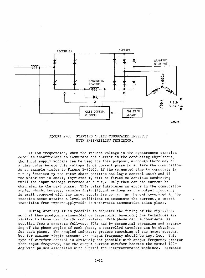
RECTIFIER INVERTER
FIGURE 2-8. STARTING A LINE-COMNUTATED INVERTER WITH FREEWHEELING THYRISTOR.
At low frequencies, when the induced voltage in the synchronous traction motor is insufficient to commutate the current in the conducting thyristors, the input supply voltage can be used for this purpose, although there may be a time delay before this voltage is of correct phase to achieve the commutation. As an example (refer to Figure 2-9(b)), if the requested time to commutate is t = tj (decided by the rotor shaft position and logic control unit) and if the motor emf is small, thyristor T^ will be forced to continue conducting until the input voltage reverses at t = t2» Only then can the current be channeled to the next phase. This delay introduces an error in the commutation angle, which, however, remains insignificant as long as the output frequency is small compared with the input supply frequency. As the emf generated in the traction motor attains a level sufficient to commutate the current, a smooth transition from input-supply-side to motor-side commutation takes place.
During starting it is possible to sequence the firing of the thyristors so that they produce a sinusoidal or trapezoidal waveform; the techniques are similar to those used in cycloconverters. Each phase can be considered as supplied from a separate full-wave PDR; and by sequential advancing and retarding of the phase angles of each phase, a controlled waveform can be obtained for each phase. The coupled inductors produce smoothing of the motor current, but for minimum ripple* content the output frequency should be kept low. This type of waveform control is obviously not possible with output frequency greater than input frequency, and the output current waveform becomes the normal 120- deg-wide pulses associated with current-fed line-commutated machines. Harmonic
2-12
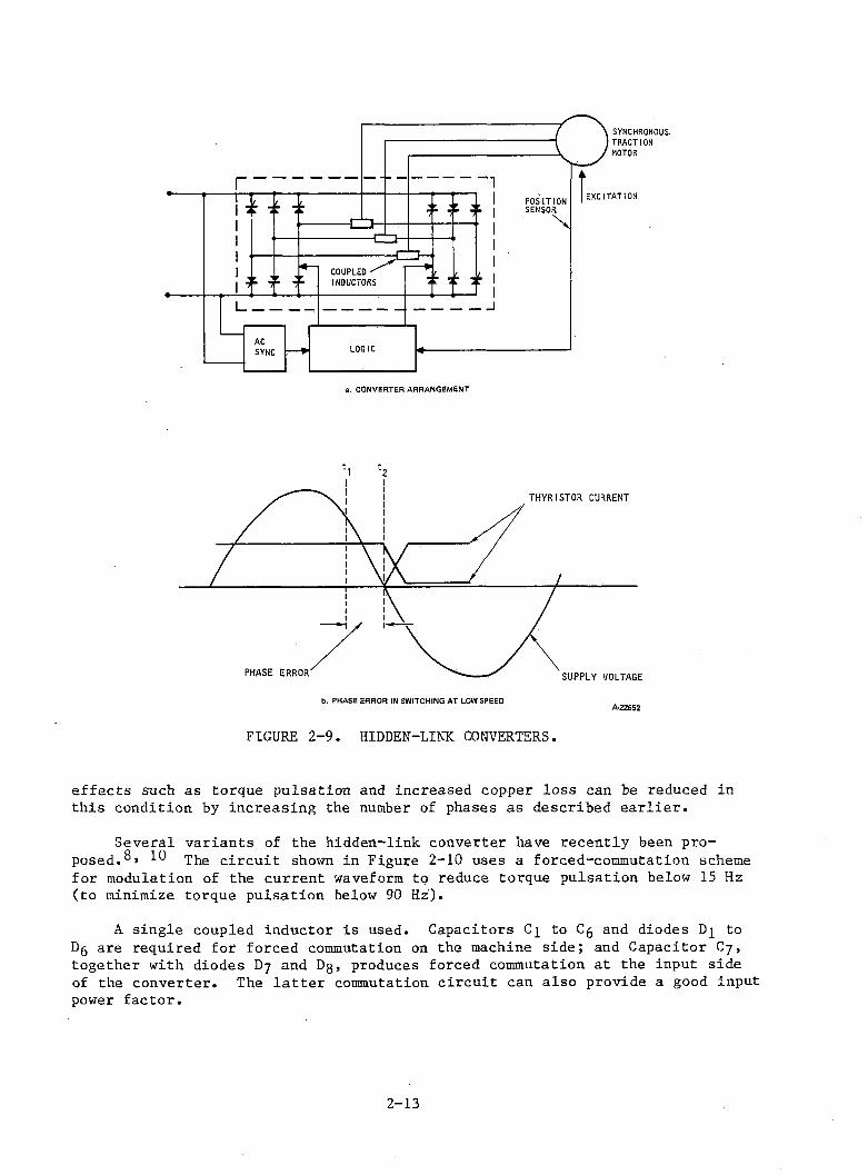
a. CONVERTER ARRANGEMENT
FIGURE 2-9. HIDDEN-LINK CONVERTERS.
effects such as torque pulsation and increased copper loss can be reduced in this condition by increasing the number of phases as described earlier.
Several variants of the hidden-link converter have recently been proposed. xhe circuit shown in Figure 2-10 uses a forced-commutation schemefor modulation of the current waveform to reduce torque pulsation below 15 Hz (to minimize torque pulsation below 90 Hz).
A single coupled inductor is used. Capacitors C^ to Cg and diodes D^ to Dg are required for forced commutation on the machine side; and Capacitor C7 , together with diodes D7 and Dg, produces forced commutation at the input side of the converter. The latter commutation circuit can also provide a good input power factor.
2-13
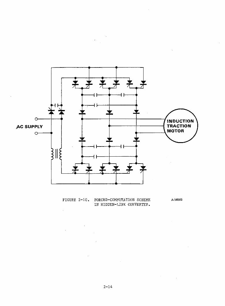
FIGURE 2-10. FORCED-COMMUTATION SCHEME A-14593IN HIDDEN-LINK CONVERTER.
2-14

A further variant^ is shown later in Figure 2-10(b). Two forced-coramutation devices pcm and ncm are shown. The black thyristors act as freewheeling paths.At low frequency, trapezoidal current shapes are generated by using a chopper action of the bridge; at high frequency, a 120-deg-wide pulse is produced.
f. Capacitor-assisted CSI with Series Blocking Diodes to Supply AsynchronousTraction Motors. If an induction-type traction motor is to be used in
conjunction with a thyristor inverter, then either static capacitors must be connected across its input terminals to obtain a leading input power factor or a force-commutated inverter is required. Although these inverters are more expensive than the line-commutated kinds described earlier, they have the advantage of being compatible with pulsewidth modulation techniques to minimize the harmonic content in their output current waveforms. Figure 2-11 shows the most common parallel-capacitor-commutated circuit, which uses a six-pulse waveform. This circuit operates with the so-called autosequential phase commutation and, therefore, does not need separate commutation thyristors. Appendix D describes the commutation process.
The output waveform of this CSI is a 120-deg-wide pulse, as shown in Figure 2-12(a). Such rectangular current is known to produce torque pulsations in the motor at six times supply frequency. In traction applications the inverter- induced resonance of the mechanical drive train can typically occur at low
INPUT CONVERTER (PDR) OUTPUT CONVERTER
INDUCTIONTRACTIONMOTOR
/M4563
FIGURE 2-11. COMMON PARALLEL-CAPACITOR-COMMUTATED CIRCUIT.
2-15
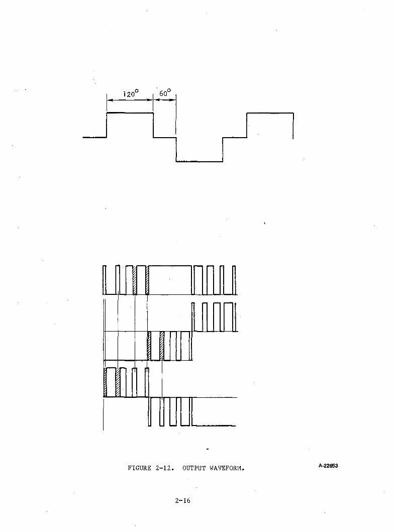
120° 60o
FIGURE 2-12. OUTPUT WAVEFORM A-22653
2 - 1 6
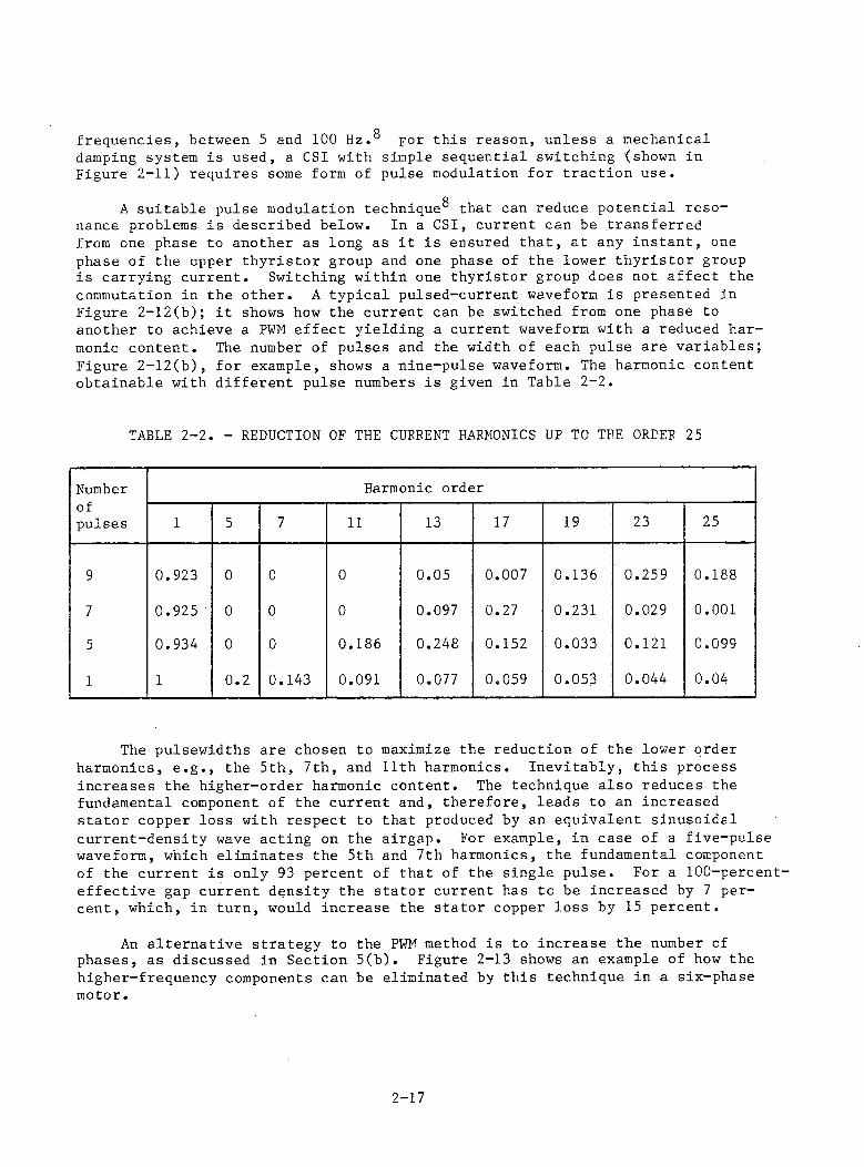
ofrequencies, between 5 and 100 Hz.° for this reason, unless a mechanical damping system is used, a CSI with simple sequential switching (shown in Figure 2-11) requires some form of pulse modulation for traction use.
OA suitable pulse modulation technique0 that can reduce potential resonance problems is described below. In a CSI, current can be transferred from one phase to another as long as it is ensured that, at any instant, one phase of the upper thyristor group and one phase of the lower thyristor group is carrying current. Switching within one thyristor group does not affect the commutation in the other. A typical pulsed-current waveform is presented in Figure 2-12(b); it shows how the current can be switched from one phase to another to achieve a PWM effect yielding a current waveform with a reduced harmonic content. The number of pulses and the width of each pulse are variables; Figure 2-12(b), for example, shows a nine-pulse waveform. The harmonic content obtainable with different pulse numbers is given in Table 2-2.
TABLE 2-2. - REDUCTION OF THE CURRENT HARMONICS UP TO THE ORDER 25
Number Harmonic orderofpulses 1 5 7 11 13 17 19 23 25
9 0.923 0 0 0 0.05 0.007 0.136 0.259 0.188
7 0.925 0 0 0 0.097 0.27 0.231 0.029 0.001
5 0.934 0 0 0.186 0.248 0.152 0.033 0.121 0.099
1 1 0.2 0.143 0.091 0.077 0.059 0.053 0.044 0.04
The pulsewidths are chosen to maximize the reduction of the lower order harmonics, e.g., the 5th, 7th, and 11th harmonics. Inevitably, this process increases the higher-order harmonic content. The technique also reduces the fundamental component of the current and, therefore, leads to an increased stator copper loss with respect to that produced by an equivalent sinusoidal current-density wave acting on the airgap. For example, in case of a five-pulse waveform, which eliminates the 5th and 7th harmonics, the fundamental component of the current is only 93 percent of that of the single pulse. For a 100-percent- effective gap current density the stator current has to be increased by 7 percent, which, in turn, would increase the stator copper loss by 15 percent.
An alternative strategy to the PWM method is to increase the number of phases, as discussed in Section 5(b). Figure 2-13 shows an example of how the higher-frequency components can be eliminated by this technique in a six-phase motor.
2 - 1 7
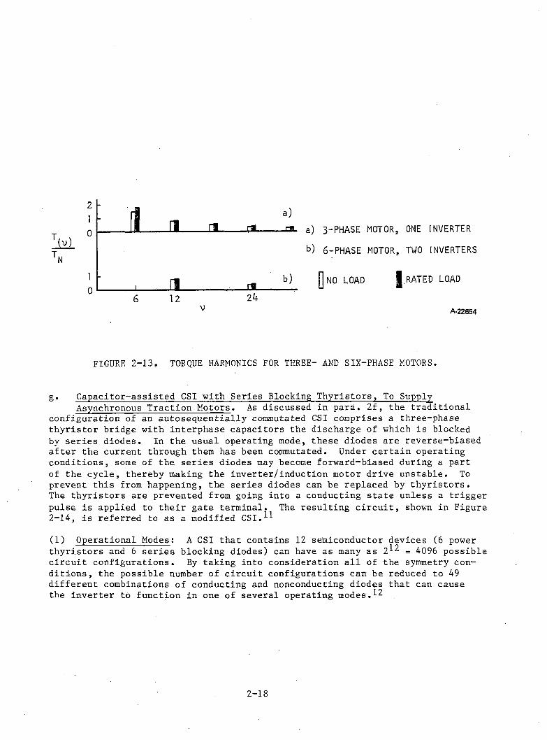
(v)
-1 n n rs
a)rsa
i _3__ m b)12 v 24
b) 6-PHASE MOTOR, TWO INVERTERS
jj NO LOAD | RATED LOAD
A-22654
FIGURE 2-13. TORQUE HARMONICS FOR THREE- AND SIX-PHASE MOTORS.
g. Capacitor-assisted CSI with Series Blocking Thyristors, To SupplyAsynchronous Traction Motors. As discussed in para. 2f, the traditional
configuration of an autosequentially commutated CSI comprises a three-phase thyristor bridge with interphase capacitors the discharge of which is blocked by series diodes. In the usual operating mode, these diodes are reverse-biased after the current through them has been commutated. Under certain operating conditions, some of the series diodes may become forward-biased during a part of the cycle, thereby making the inverter/induction motor drive unstable. To prevent this from happening, the series diodes can be replaced by thyristors.The thyristors are prevented from going into a conducting state unless a trigger pulse is applied to their gate terminal. The resulting circuit, shown in Figure 2-14, is referred to as a modified CSI.^
(1) Operational Modes: A CSI that contains 12 semiconductor devices (6 powerthyristors and 6 series blocking diodes) can have as many as 2^ _ 4096 possible circuit configurations. By taking into consideration all of the symmetry conditions, the possible number of circuit configurations can be reduced to 49 different combinations of conducting and nonconducting diodes that can cause the inverter to function in one of several operating modes.
2 - 1 8
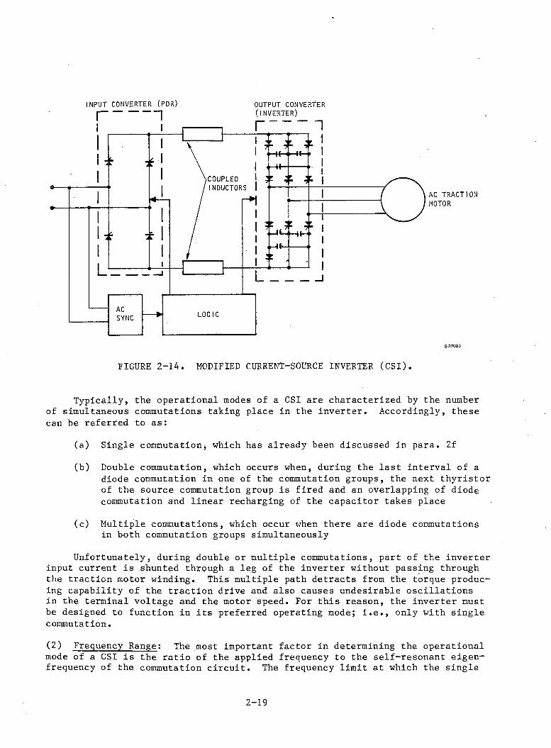
INPUT CONVERTER (PDR) OUTPUT CONVERTER
AC TRACTION MOTOR
S-37003
FIGURE 2-14. MODIFIED CURRENT-SOURCE INVERTER (CSI).
Typically, the operational modes of a CSI are characterized by the number of simultaneous commutations taking place in the inverter. Accordingly, these can be referred to as:(a) Single commutationi which has already been discussed in para. 2f(b) Double commutation, which occurs when, during the last interval of a diode commutation in one of the commutation groups, the next thyristor of the source commutation group is fired and an overlapping of diode commutation and linear recharging of the capacitor takes place(c) Multiple commutations, which occur when there are diode commutations in both commutation groups simultaneouslyUnfortunately, during double or multiple commutations, part of the inverter input current is shunted through a leg of the inverter without passing through the traction motor winding. This multiple path detracts from the torque producing capability of the traction drive and also causes undesirable oscillations in the terminal voltage and the motor speed. For this reason, the inverter must be designed to function in its preferred operating mode; i.e., only with single commutation.
(2) Frequency Range: The most important factor in determining the operationalmode of a CSI is the ratio of the applied frequency to the self-resonant eigen- frequency of the commutation circuit. The frequency limit at which the single
2-19
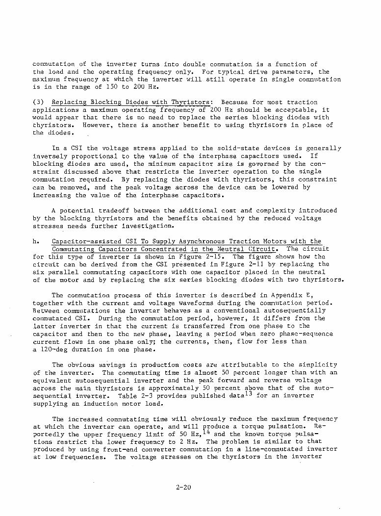
commutation of the inverter turns into double commutation is a function of the load and the operating frequency only. For typical drive parameters, the maximum frequency at which the inverter will still operate in single commutation is in the range of 150 to 200 Hz.
(3) Replacing Blocking Diodes with Thyristors: Because for most tractionapplications a maximum operating frequency of 200 Hz should be acceptable, it would appear that there is no need to replace the series blocking diodes with thyristors. However, there is another benefit to using thyristors in place of the diodes.
In a CSI the voltage stress applied to the solid-state devices is generally inversely proportional to the value of the interphase capacitors used. If blocking diodes are used, the minimum capacitor size is governed by the constraint discussed above that restricts the inverter operation to the single commutation required. By replacing the diodes with thyristors, this constraint can be removed, and the peak voltage across the device can be lowered by increasing the value of the interphase capacitors.
A potential tradeoff between the additional cost and complexity introduced by the blocking thyristors and the benefits obtained by the reduced voltage stresses needs further investigation.
h. Capacitor-assisted CSI To Supply Asynchronous Traction Motors with theCommutating Capacitors Concentrated in the Neutral Circuit. The circuit
for this type of inverter is shown in Figure 2-15. The figure shows how the circuit can be derived from the CSI presented in Figure 2-11 by replacing the six parallel commutating capacitors with one capacitor placed in the neutral of the motor and by replacing the six series blocking diodes with two thyristors.
The commutation process of this inverter is described in Appendix E, together with the current and voltage waveforms during the commutation period. Between commutations the inverter behaves as a conventional autosequentially commutated CSI. During the commutation period, however, it differs from the latter inverter in that the current is transferred from one phase to the capacitor and then to the new phase, leaving a period when zero phase-sequence current flows in one phase only; the currents, then, flow for less than a 120-deg duration in one phase.
The obvious savings in production costs are attributable to the simplicity of the inverter. The commutating time is almost 50 percent longer than with an equivalent autosequential inverter and the peak forward and reverse voltage across the main thyristors is approximately 50 percent above that of the autosequential inverter. Table 2-3 provides published data^ for an inverter supplying an induction motor load.
The increased commutating time will obviously reduce the maximum frequency at which the inverter can operate, and will produce a torque pulsation. Reportedly the upper frequency limit of 50 Hz,1 and the known torque pulsations restrict the lower frequency to 2 Hz. The problem is similar to that produced by using front-end converter commutation in a line-commutated inverter at low frequencies. The voltage stresses on the thyristors in the inverter
2-20
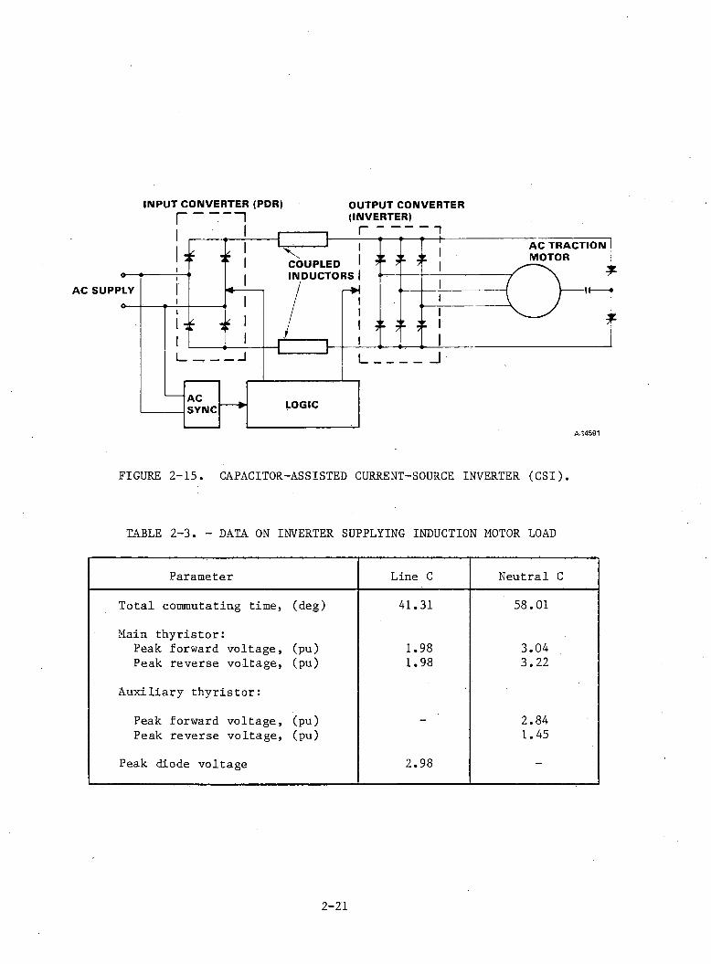
INPUT CONVERTER (PDR) OUTPUT CONVERTERI----- ;-- 1 (INVERTER)
A-14591
FIGURE 2-15. CAPACITOR-ASSISTED CURRENT-SOURCE INVERTER (CSI).
TABLE 2-3. - DATA ON INVERTER SUPPLYING INDUCTION MOTOR LOAD
Parameter Line C Neutral C
Total commutating time, (deg) 41.31 58.01
Main thyristor:Peak forward voltage, (pu) 1.98 3.04Peak reverse voltage, (pu) 1.98 3.22
Auxiliary thyristor:
Peak forward voltage, (pu) - 2.84Peak reverse voltage, (pu) 1.45
Peak diode voltage 2.98 -
2-21

are higher than those in the autosequential inverter, but it is likely that rectifier grade components can be used without employing large snubber circuits or suffering high switching and commutating losses.
In traction applications the advantages of the neutral commutated inverter — the low parts count, small snubber components, and rectifier grade devices— must be traded off against the reduced starting torque and frequency range and increased torque pulsation. A possible method of reducing torque is to use a multiple-inverter arrangement, so that the parallel inverter is able to maintain output torque during commutation.
2-22
REFERENCES
1. Sholtis, G., "Three-Phase Drives— the Many Advantages Which Passenger Urban Transit Can Obtain," Rail Engineering International, October/December 1979.
2. Stocken, A.R., "Synchronous Motor Variable-Speed, A.C. Drive System," IEE Conference on Electrical Variable-Speed Drivers, Pub. No. 179, 1979,pp. 58-60.
3. Feltbower, B., "Machine-commutated Inverter Drives of Large Power," IEE Conference on Electrical Variable-Speed Drivers, Pub. No. 179, 1979, pp. 61-65.
4. Viarouge, P., "Study and Implementation of a Digital Process for an Autopiloted Current-fed Synchronous Machine," Proc. International Conference on Electrical Machines, Athens, 1980.
5. Le-Huy, H., "Starting Scheme for a Microprocessor-based Converter-fed Self-Control Synchronous Motor Drive," Proc. International Conference on Electrical Machines, Athens, 1980, pp. 946-953.
6. Williamson, A.C., "Low-Speed Commutation of an Inverter-fed Synchronous Motor," Proc. International Conference on Electrical Machines, Athens, 1980, pp. 1028—1035.
7. Noriaki, Sato, "Adjustable Speed Drive with a Brushless D.C. Motor," I.E.E.E. I.G.A., July/August 1971, p. 539.
8. Lienau, W., "Power Converters for Feeding Asynchronous Traction Motors of Single-Phase A.C. Vehicles," I.E.E.E. T.I.A. Vol. IA-16, No. 1.
9. Konya, Y., "A New Current-Source Inverter for Induction Motor Drive System," Proc. Electrical Variable-Speed Drives Conference, Pub. No. 179, I.E.E., London.
10. Bondarenko, "The VL80B Type Electric Locomotive with Rectifier Traction Motor," Rail International, April 1977.
11. Joshi, A., and S. B. Dewan, "Modified Current Source Inverter for Squirrel Cage Motor Drive," IEGE Transactions on Magnetics, Vol. MAG-14, No. 5, September 1978, pp. 930-932.
12. Lienau, W., "Commutation Modes of a Current-Source Inverter," Second IFAC Symposium on Control in Power Electronics and Electrical Drives,Dusseldorf, 1977, pp. 217-229.
13. Steigerwald, R.L., "Characteristics of a Current-fed Inverter with Commutation Applied Through Load Neutral Point," I.E.E.E., Vol IA-15, No. 5,1979.
14. Van Wyk, J.E., "A Simple and Reliable Four-Quadrant Variable-Frequency A.C. Drive for Industrial Application'up to 50 KW," Proc. I.E.E. Conference on Electrical Variable-Speed Drives, Pub. No. 179, 1979.
2-23
3. CANDIDATE AC TRACTION MOTORS.
a. Introduction. Ac traction motors that can be used in conjunction with solid-state supplies are:
(1) Polyphase induction motors
(2) Polyphase synchronous motors
(3) Polyphase reluctance motors
b. Polyphase Induction Motors. The polyphase squirrel-cage induction machine is probably the most attractive motor for traction purposes. It has a rugged, inexpensive construction and requires minimum maintenance. It is suitable for running at high speed, since the brushless squirrel-cage construction is able to withstand high centrifugal forces. This increase in speed provides a higher power/volume ratio than can be obtained with a conventional dc commutator-type traction motor, except where the unit is subject to limitations introduced bya higher-ratio gearbox required at the axle. Induction motors are also capable of operating at good efficiency and power factor over a wide speed range and have an ability to withstand momentary electrical or magnetic overload without damage. An undesirable feature of an induction motor, however, which has to be considered during its selection for traction motor duty, is its inability to operate at leading power factor, which implies that an induction motor cannot be supplied from an LCI without having a capacitive load connected across its terminals to provide a leading component of current. This is unfortunate, because it means that the least expensive traction motor (the squirrel-cage induction type) and the least expensive inverter (the LCI) are basically not compatible.
Several design problems affect the performance of an inverter-fed induction motor. In addition to problems created by harmonics and torque pulsations, discussed in Sections 4 and 5, the following design aspects are of Considerable interest in traction applications. 1 Skin effect is particularly critical to the performance of ac traction motors when high frequency harmonics are present. The choice of pole number is obviously also important. An increase in pole number has the beneficial effect of reducing the flux per pole, and thus decreases the requirements for large back-iron depth and coil overhang. An increase in pole number, however, increases the iron losses and the magnetizing current, and, by reducing the number of slots per pole per phase, also increases the harmonic content. A high frequency will also result in increased inverter losses.
The leakage inductance has an important effect on the induction motor performance. If a voltage-fed inverter is used, the leakage inductance has to be high to reduce harmonic currents. On the other hand, current source inverters require induction motors with a low leakage inductance to reduce the switching spikes in the voltage waveforms. The insulation requirements of traction motors fed from current source inverters can be more severe than those associated with voltage-fed inverters because of the inductive voltage spikes produced at current switching. In addition, the relationship between the pull-out torque and the leakage inductance must be considered during the design process.
3-1
The torque-speed curve of a high-efficiency induction motor has a high negative slope near synchronous speed to ensure that the traction motor operates at a low-slip value. This characteristic enables the wheelslip to be quickly corrected, but does not accommodate different wheel diameters in a multi-axle drive with separate motors on each axle. It is therefore likely that unless severe restrictions are imposed on the wheel diameter variation, each axle must be supplied from a separate inverter.
A novel form of induction motor capable of running at leading power factor with possible applications for traction duty has recently been proposed.^^The rotor has a conventional squirrel-cage winding whereas the stator winding consists of two separate three-phase sections: the 'primary' or main section and the 'asynchronous condensor' (ASC) section, as shown in Figure 3-1. The ASC winding can be connected either in parallel or Series with the main winding to correct the power factor. When the windings are in parallel, the arrangement is analogous to an induction motor with a synchronous condenser connected in parallel. The input current in this arrangement is the sum of the lagging induction motor current and the leading current drawn by the condenser. If the latter component is sufficiently large, the resultant input current can be made to lead the applied voltage. Such a system will enable the motor to operate from a line-commutated inverter (as in the TLRV-system) but does not, as such, improve the output power of the induction motor by enabling the flux density and current density waves to be in phase, as is the case in a conventional synchronous motor.
The interaction between the primary and the ASC windings, both of which are coupled to the rotor cage, is complex and can be explained in terms of space transients produced by the movement of rotor bars as they pass from under the main winding section into the ASC section*^ This behavior is analogous to the exit edge effects produced in linear induction motors, whereby the rotor currents carry flux from the main section into the ASC section.
A cursory inspection of this machine indicates that it might lead to a larger frame size than a corresponding induction motor, because some fraction of the winding space is occupied by the ASC that produces the synchronous condenser action, and the torque produced in the space left for the induction motor winding is reduced by the space harmonics due to the non-uniform magnetic field distribution around the periphery.
To assess the viability of this approach, the performance of a 4-pole, 150- hp motor^ will be discussed here briefly. The primary winding is star connected, with two parallel paths per phase, and is located in 60 slots. The rotor is of squirrel-cage construction with 94 slots giving an increase in apparent starting resistance of 105 percent as a result of the deep bar effect. The connection used for the motor is given in Figure 3-2. The ASC phases D, E, and F are connected in parallel with the main windings A, B, C. When the motor is supplied from 50 Hz, it runs at 725 rpm (3.3-percent slip) at a 150-hp load. The primary winding operates at a 0.91 lagging power factor and the ASC winding operates at a 0.07 leading power factor. Because these windings are connected in parallel, they are designed for the same voltage, and their relative VA rating for the main versus ASC windings is 1:0.42, respectively. At equal electromagnetic loading for each winding and using the VA ratio above, the ASC winding would require 30 percent of the total volume. Since the volume
3-2
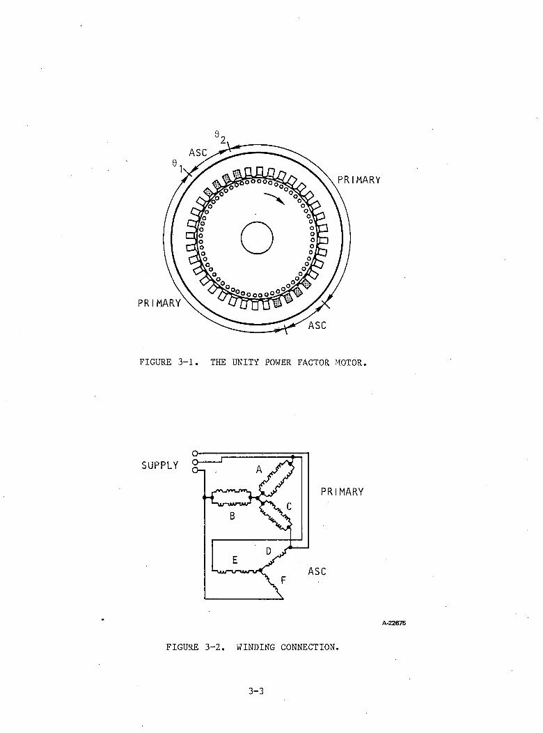
FIGURE 3-1. THE UNITY POWER FACTOR MOTOR.
SUPPLY
A-22675
FIGURE 3-2. WINDING CONNECTION.
3-3
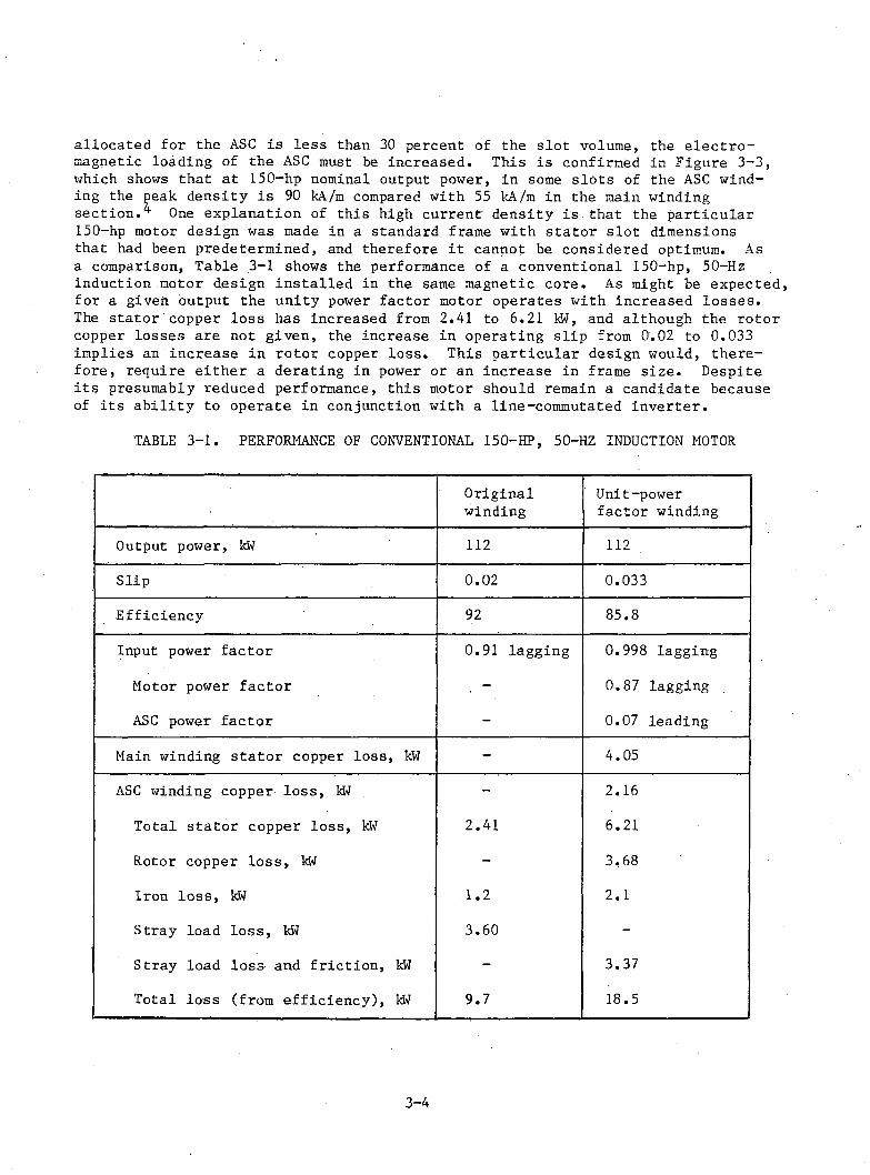
allocated for the ASC is less than 30 percent of the slot volume, the electromagnetic loading of the ASC must be increased. This is confirmed in Figure 3-3, which shows that at 150-hp nominal output power, in some slots of the ASC winding the peak density is 90 kA/m compared with 55 kA/m in the main winding section. One explanation of this high current' density is that the particular 150-hp motor design was made in a standard frame with stator slot dimensions that had been predetermined, and therefore it cannot be considered optimum. As a comparison, Table 3-1 shows the performance of a conventional 150-hp, 50-Hz induction motor design installed in the same magnetic core. As might be expected, for a given output the unity power factor motor operates with increased losses.The stator copper loss has increased from 2.41 to 6.21 Idtf, and although the rotor copper losses are not given, the increase in operating slip from 0.02 to 0.033 implies an increase in rotor copper loss. This particular design would, therefore, require either a derating in power or an increase in frame size. Despite its presumably reduced performance, this motor should remain a candidate because of its ability to operate in conjunction with a line-commutated inverter.
TABLE 3-1. PERFORMANCE OF CONVENTIONAL 150-HP, 50-HZ INDUCTION MOTOR
Originalwinding
Unit-power factor winding
Output power, kW 112 112
Slip 0.02 0.033
Efficiency 92 85.8
Input power factor 0.91 lagging 0.998 lagging
Motor power factor - 0.87 lagging
ASC power factor - 0.07 leading
Main winding stator copper loss, kW - 4.05
ASC winding copper loss, kW - 2.16
Total stator copper loss, kW 2.41 6.21
Rotor copper loss, kW - 3.68
Iron loss, kW 1.2 2.1
Stray load loss, kW 3.60 -Stray load loss and friction, kW - 3.37
Total loss (from efficiency), kW 9.7 18.5
3-4
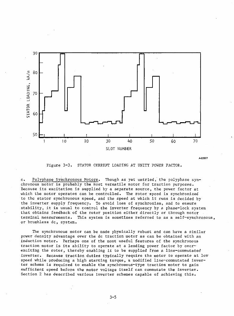
A -2 2 6 7 7
Figure 3-3. STATOR CURRENT LOADING AT UNITY POWER FACTOR.
c. Polyphase Synchronous Motors. Though as yet untried, the polyphase synchronous motor is probably the most versatile motor for traction purposes.Because its excitation is supplied by a separate source, the power factor at which the motor operates can be controlled. The rotor speed is synchronized to the stator synchronous speed, and the speed at which it runs is decided by the inverter supply frequency. To avoid loss of synchronism, and to ensure stability, it is usual to control the inverter frequency by a phase-lock system that obtains feedback of the rotor position either directly or through motor terminal measurements. This system is sometimes referred to as a self-synchronous, or brushless dc, system.
The synchronous motor can be made physically robust and can have a similar power density advantage over the dc traction motor as can be obtained with an induction motor. Perhaps one of the most useful features of the synchronous traction motor is its ability to operate at a leading power factor by overexciting the rotor, thereby enabling it to be supplied from a line-commutated inverter. Because traction duties typically require the motor to operate at low speed while producing a high starting torque, a modified line-commutated inverter scheme is required to enable the synchronous-type traction motor to gain sufficient speed before the motor voltage itself can commutate the inverter.Section 2 has described various inverter schemes capable of achieving this.
3-5
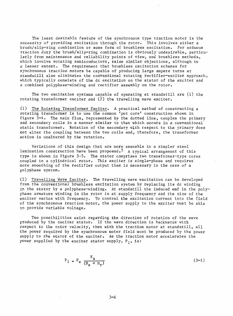
The least desirable feature of the synchronous type traction motor is the necessity of providing excitation through the rotor. This involves either a brush/slip-ring combination or some form of brushless excitation. For arduous traction duty the brush/slip-ring combination is obviously undesirable, particularly from maintenance and reliability points of view, and brushless methods, which involve rotating semiconductors, raise similar objections, although to a lesser extent. The requirement that brushless excitation schemes for synchronous traction motors be capable of producing large ampere turns at standstill also eliminates the conventional rotating rectifier-exciter approach, which typically consists of the dc excitation on the stator of the exciter and a combined polyphase-winding and rectifier assembly on the rotor.
The two excitation systems capable of operating at standstill are (1) the rotating transformer exciter and (2) the travelling wave exciter.
(1) The Rotating Transformer Exciter. A practical method of constructing a rotating transformer is to use the common 'pot core' construction shown in Figure 3-4. The main flux, represented by the dotted line, couples the primary and secondary coils in a manner similar to that which occurs in a conventional static transformer. Rotation of the secondary with respect to the primary does not alter the coupling between the two coils and, therefore, the transformer action is unaltered by the rotation.
Variations of this design that are more amenable to a simpler steel lamination construction have been proposed.^ A typical arrangement of this type is shown in Figure 3-5. The stator comprises two transformer-type cores coupled to a cylindrical rotor. This exciter is single-phase and requires more smoothing of the rectifier output than is necessary in the case of a polyphase system.
(2) Travelling Wave Exciter. The travelling wave excitation can be developed from the conventional brushless excitation system by replacing its dc windingin the stator by a polyphase-winding. At standstill the induced emf in the polyphase armature winding in the rotor is at supply frequency and the size of the exciter varies with frequency. To control the excitation current into the field of the synchronous traction motor, the power supply to the exciter must be able to provide variable voltage.
Two possibilities exist regarding the direction of rotation of the wave produced by the exciter stator. If the wave direction is backwards with respect to the rotor velocity, then with the traction motor at standstill, all the power required by the synchronous motor field must be produced by the power supply to the stator of the exciter. As the traction motor accelerates the power supplied by the exciter stator supply, P^, is:
P1 Nr)(N« (3-1)
3 -6
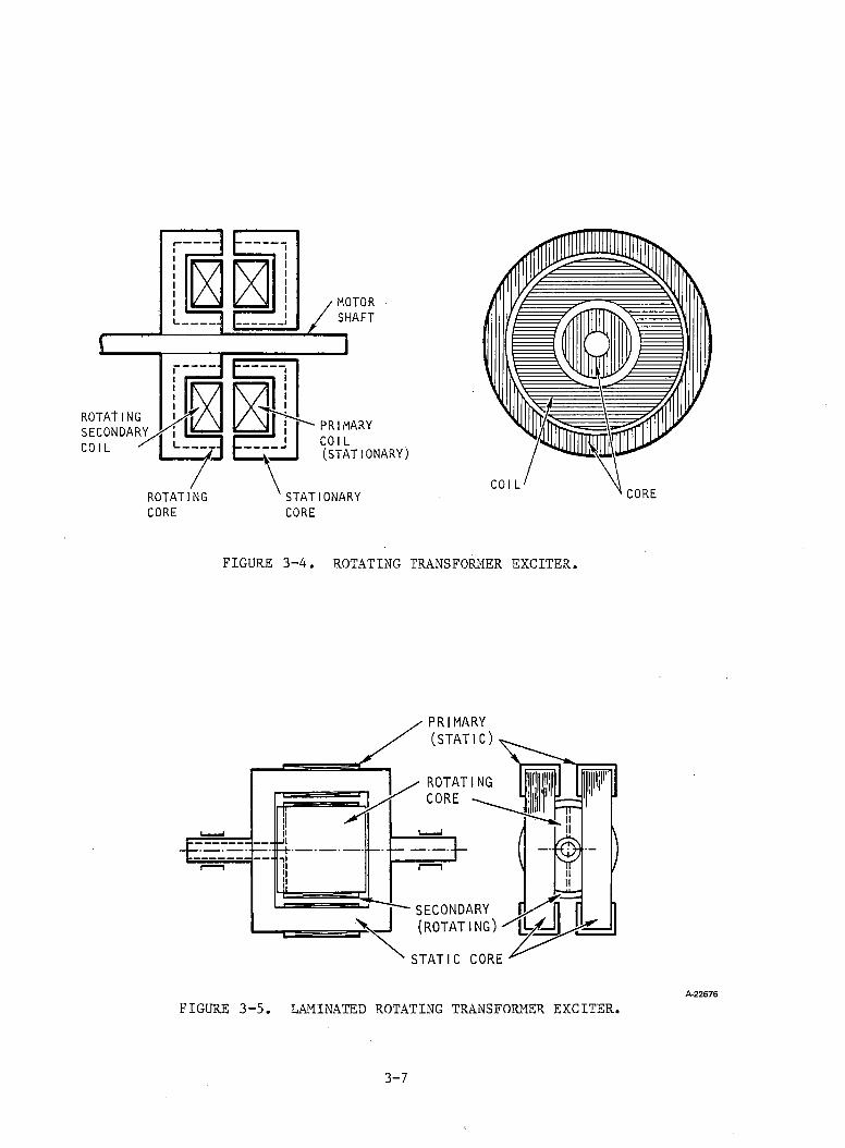
FIGURE 3-4 ROTATING TRANSFORMER EXCITER.
A -2 2 6 7 6
FIGURE 3-5. LAMINATED ROTATING TRANSFORMER EXCITER.
3-7

wherePe = power into synchronous motor field
Ns = synchronous speed of exciter stator field
Nr = rotor speedThe power required therefore reduces as the rotor accelerates, and the remainder of the power is then supplied mechanically by the synchronous motor.
If the travelling wave in the exciter stator is moving in the same direction as the rotor, the nature of the operation changes considerably. While at standstill the situation is identical to that of the backward travelling excitation wave, with all the power being provided through the exciter stator supply; but as the motor accelerates, the power required from the exciter stator supply, Pj, increases because it now supplies the required electrical power to the rotating rectifier plus a mechanical output power. Some of the motor output torque is therefore being supplied by the exciter. The power supplied by the exciter stator supply, P^, is given by:
Pi = P, (Ns - Nr) (3-2)
The synchronous speed must obviously be greater than the maximum rotor speed to keep P^ at a minimum; and to keep the dimensions similar to those of a conventional dc exciter system, this synchronous speed should be twice that of the maximum rotor speed.
To minimize the rating of the stator supply inverter, a backward travelling wave is, therefore, the best choice. The size of this exciter depends on the frequency of the supply: if the frequency is increased, the size of the exciter reduces since the relative velocity of the stator wave is increased and the generated voltage per turn increases. At the same time, however, the iron losses in the core increase and the switching losses in the supply and the rectifier bridge will also increase. A tradeoff between core cost, supply cost, and exciter dimensions is needed.
d. Polyphase Reluctance Motors. There has been recent interest in the use of reluctance motors for traction p u r p o s e s . A l t h o u g h the reluctance motor is of robust construction, it has not been used in traction applications because of its historically low power factor and low output per volume. Recent improvements in the design of reluctance motors, however, have yielded performances that are comparable to that of the three-phase squirrel-cage induction motor.The reluctance motor proposed for traction purposes has double saliency (i.e., it has salient poles on both its rotor and stator) and, therefore, closely resembles a stepper motor, with the switching angle controlled by the rotor position. The number of poles on the stator and rotor are not equal and the ratio is typically chosen to enable starting in either direction from any rotor position. To obtain adequate starting torque, different numbers of phases are possible as in a stepper motor connection.
3-8
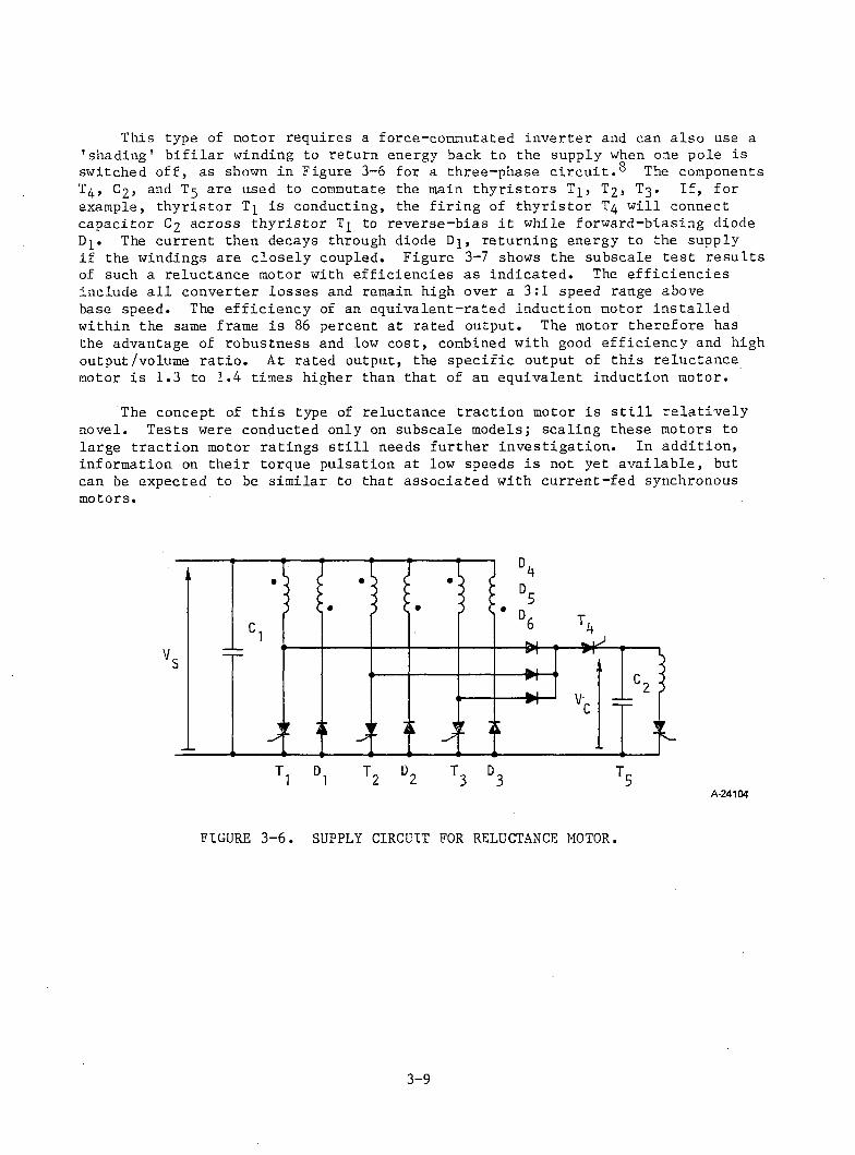
This type of motor requires a force-commutated inverter and can also use a 'shading' bifilar winding to return energy back to the supply when one pole is switched off, as shown in Figure 3-6 for a three-phase circuit.^ The components T4 , C2 , and T5 are used to commutate the main thyristors T]_, T2 , T3 . If, for example, thyristor T^ is conducting, the firing of thyristor T4 will connect capacitor C2 across thyristor T^ to reverse-bias it while forward-biasing diode Dj. The current then decays through diode Dj, returning energy to the supply if the windings are closely coupled. Figure 3-7 shows the subscale test results of such a reluctance motor with efficiencies as indicated. The efficiencies include all converter losses and remain high over a 3:1 speed range above base speed. The efficiency of an equivalent-rated induction motor installed within the same frame is 8 6 percent at rated output. The motor therefore has the advantage of robustness and low cost, combined with good efficiency and high output/volume ratio. At rated output, the specific output of this reluctance motor is 1.3 to 1.4 times higher than that of an equivalent induction motor.
The concept of this type of reluctance traction motor is still relatively novel. Tests were conducted only on subscale models; scaling these motors to large traction motor ratings still needs further investigation. In addition, information on their torque pulsation at low speeds is not yet available, but can be expected to be similar to that associated with current-fed synchronous motors.
A-24104
FIGURE 3-6. SUPPLY CIRCUIT FOR RELUCTANCE MOTOR.
3-9
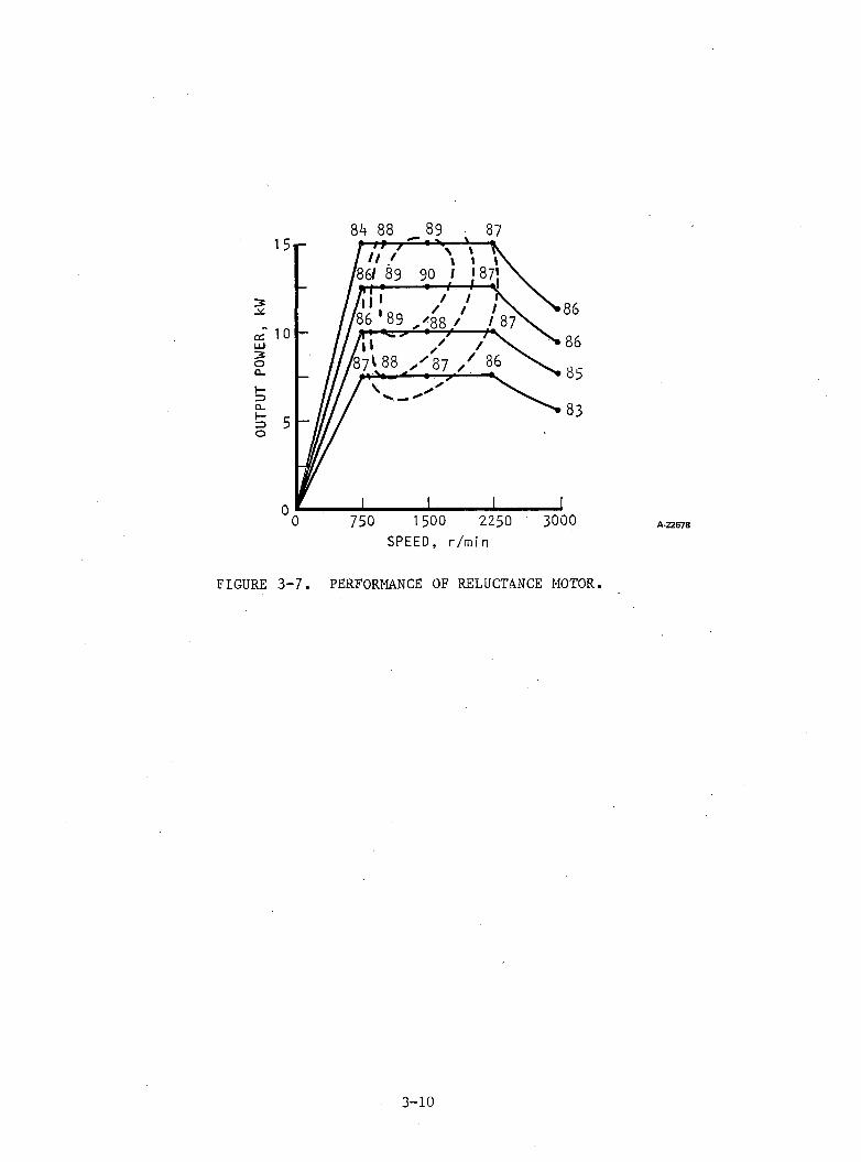
FIGURE 3-7. PERFORMANCE OF RELUCTANCE MOTOR.
A -2 2 6 7 8
3-10
REFERENCES
1. Del-Pizzo, A., "Eddy Current Evaluation for Inverter-Fed Motors,"Proceedings, International Conference on Electrical Machines, Athens, 1980.
2. Tartello, E., "Variable Frequency Inverter-Fed Asynchronous Motor Design," Proceedings, International Conference on Electrical Machines, Athens, 1980.
3. Laithwaite, E.R., "The Development of a Unity Power Factor Brushless Induction Motor," Proc. International Conference on Electrical Machines, Athens, 1980.
4. Laithwaite, E.R., "Test Results Obtained from a Brushless Unity-Power-Factor Induction Machine," IEEE PES Winter Meeting, Atlanta, Georgia, February 1981.
5. Vertini, S., "A New Brushless Excitation Device for Inverter-Fed Synchronous Motors with Variable Frequency and Voltage."
6 . Lawrenson, P.J., "Variable-Speed Switched Reluctance Motors," IEE Proc., Vol 127, Pt B, July 1980.
7. Bausch, H., "Performance of Thyristor-Fed Electric Car Reluctance Machines," Proc. International Conference on Electrical Machines, Brussels, 1978,pp. E4/2-1.
8 . Davis, R., "An Inverter Drive for a Switched Reluctaqnce Motor," Proc. International Conference on Electrical Machines, Athens, 1980.
3-11
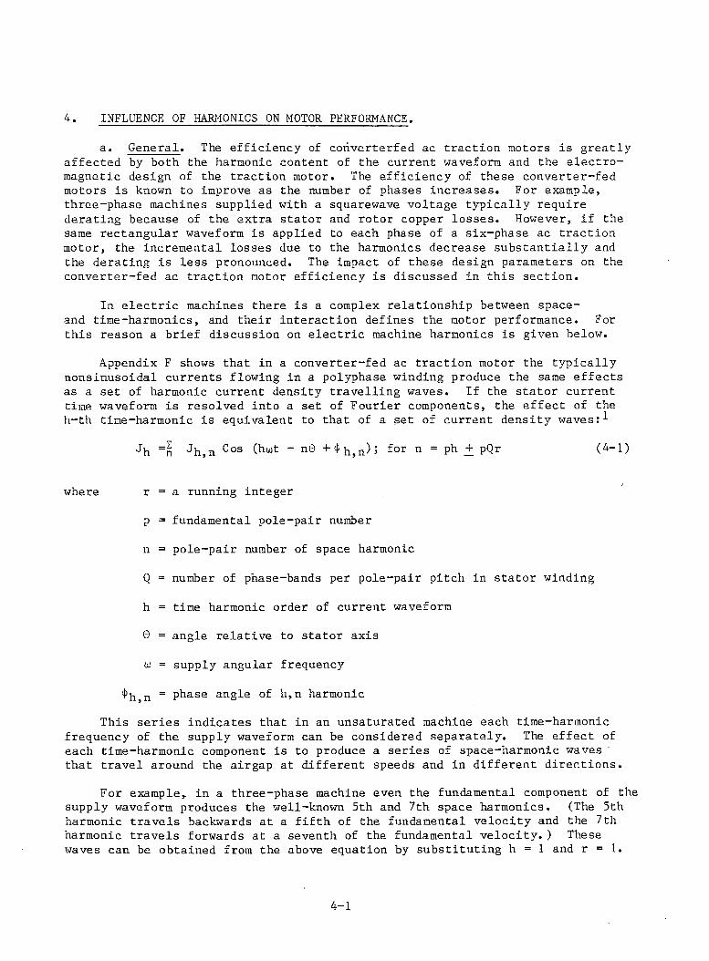
4. INFLUENCE OF HARMONICS ON MOTOR PERFORMANCE.
a. General. The efficiency of coriverterfed ac traction motors is greatly affected by both the harmonic content of the current waveform and the electromagnetic design of the traction motor. The efficiency of these converter-fed motors is known to improve as the number of phases increases. For example, three-phase machines supplied with a squarewave voltage typically require derating because of the extra stator and rotor copper losses. However, if the same rectangular waveform is applied to each phase of a six-phase ac traction motor, the incremental losses due to the harmonics decrease substantially and the derating is less pronounced. The impact of these design parameters on the converter-fed ac traction motor efficiency is discussed in this section.
In electric machines there is a complex relationship between space- and time-harmonics, and their interaction defines the motor performance. For this reason a brief discussion on electric machine harmonics is given below.
Appendix F shows that in a converter-fed ac traction motor the typically nonsinusoidal currents flowing in a polyphase winding produce the same effects as a set of harmonic current density travelling waves. If the stator current time waveform is resolved into a set of Fourier components, the effect of the h-th time-harmonic is equivalent to that of a set of current density waves
Jh =n Jh,n Cos “ n 0 + <f'h,n)5 for n = ph + pQr (4-1)
where r = a running integer
p = fundamental pole-pair number
n = pole-pair number of space harmonic
Q = number of phase-bands per pole-pair pitch in stator winding
h = time harmonic order of current waveform
0 = angle relative to stator axis
w = supply angular frequency
4>h>n = phase angle of h,n harmonicThis series indicates that in an unsaturated machine each time-harmonic
frequency of the supply waveform can be considered separately. The effect of each time-harmonic component is to produce a series of space-harmonic waves that travel around the airgap at different speeds and in different directions.
For example, in a three-phase machine even the fundamental component of the supply waveform produces the well-known 5th and 7th space harmonics. (The 5th harmonic travels backwards at a fifth of the fundamental velocity and the 7th harmonic travels forwards at a seventh of the fundamental velocity.) These waves can be obtained from the above equation by substituting h = 1 and r = 1 .
4-1
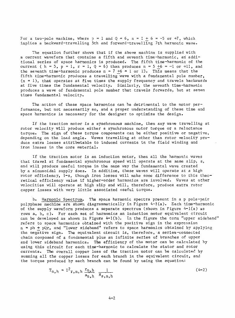
For a two-pole machine, where p = 1 and Q = 6 , n = 1 + 6 = -5 or +7, which implies a backward-travelling 5t’n and forward-travelling 7th harmonic wave.
The equation further shows that if the above machine is supplied with a current waveform that contains a fifth and seventh time-harmonic, an additional series of space harmonics is produced. The fifth time-harmonic of the current ( h = 5 , p = l , r = 1, Q = 6 ) then produces n = 5 +6 = -1 or +11, and the seventh time-harmonic produces n = 7 + 6 = 1 or 13. This means that the fifth time-harmonic produces a travelling wave with a fundamental pole number,(n = 1 ), that operates at five times the supply frequency and travels backwards at five times the fundamental velocity. Similarly, the seventh time-harmonic produces a wave of fundamental pole number that travels forwards, but at seven times fundamental velocity.
The action of these space harmonics can be detrimental to the motor performance, but not necessarily so, and a proper understanding of these time and space harmonics is necessary for the designer to optimize the design.
If the traction motor is a synchronous machine, then any wave travelling at rotor velocity will produce either a synchronous motor torque or a reluctance torque. The sign of these torque components can be either positive or negative, depending on the load angle. Waves travelling at other than rotor velocity produce extra losses attributable to induced currents in the field winding and iron losses in the core material.
If the traction motor is an induction motor, then all the harmonic waves that travel at fundamental synchronous speed will operate at the same slip, s, and will produce useful torque in the same way the fundamental wave created by a sinusoidal supply does. In addition, these waves will operate at a high rotor efficiency, 1-s, though iron losses will make some difference to this theoretical efficiency value if higher-order harmonics are involved. Waves at other velocities will operate at high slip and will, therefore, produce extra rotor copper losses with very little associated useful torque.
b. Harmonic Spectrum. The space harmonic spectra present in a p pole-pair polyphase machine are shown diagrammatically in Figure 4-1(a). Each time-harmonic of the supply waveform produces a separate spectrum (shown in Figure 4-l(a) as rows a, b, c). For each set of harmonics an induction motor equivalent circuit can be developed as shown in Figure 4-1(b). In the figure the term "upper sideband" refers to space harmonics obtained with the positive sign in the expression n = ph + pQr, and "lower sideband" refers to space harmonics obtained by applying the negative sign. The equivalent circuit is, therefore, a series-connected chain composed of a fundamental plus an infinite series of branches of upper and lower sideband harmonics. The efficiency of the motor can be calculated by using this circuit for each time-harmonic to calculate the stator and rotor currents. The overall copper loss of the traction motor can be calculated by summing all the copper losses for each branch in the equivalent circuit, and the torque produced by each branch can be found by using the equation:
n,h -*- r,n,h ___ 5;__sn,h ^s,n,h
(4-2)
4-2
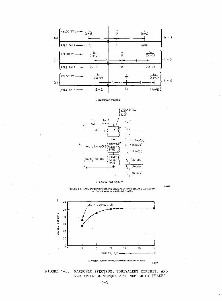
TORQUE
, per
cent
a. H A R M O N IC S P E C T R A .
FUNDAMENTALROTORBRANCHr, P
h l
hp' hprH,p (ph+pQk)6 (ph+pQk)1I. (ph+pQk)1rh (ph-pQk)1i5, (ph-pQk)1I, (ph-pQk)1
b. E Q U I V A L E N T C IR C U IT .
A-22683F I G U R E 4 -1 . H A R M O N IC S P E C T R U M A N D E Q U I V A L E N T C IR C U IT , A N D V A R I A T IO N
O F T O R Q U E W IT H N U M B E R S O F P H A S E S .
c. V A R I A T IO N O F T O R Q U E W IT H N U M B E R O F P H A S E S .A-22682
FIGURE 4-1. HARMONIC SPECTRUM, EQUIVALENT CIRCUIT, AND VARIATION OF TORQUE WITH NUMBER OF PHASES
4-3
where Ir>n,h = rotor current due to h-th time-harmonic and n pole-pair space-harmonic
rn h = rotor resistance for the space-harmonic
^s,n,h = synchronous speed (rad/sec) for the space harmonic
sn,h = slip for the space-harmonic
Once the rotor and stator currents are known, the flux density waves can be calculated for each space-harmonic, and the complete flux density in the air gap of the traction motor can then be reconstructed by summing these component waves. This enables tooth flux densities and back-iron flux densities in the machine to be .calculated.
c. Number of Phases. The variation of losses with the number of phase- bands is an important design consideration for traction motors. Figure 4-1(c) shows the improvement in the torque-producing capability of a traction motor, supplied with a squarewave voltage, as the number of phasebands, Q, increases.For each design point shown in Figure 4-1(c), the magnetic and electrical circuits are fully loaded to their practical limit. The torque in Figure 4-1(c) is expressed as a percentage of that obtained with a sinusoidal applied voltage and the point shown as "delta connection" corresponds to a supply with a 1 2 0 - deg-wide rectangular waveform containing no triplen harmonics.
The main reason for the increased output that can be obtained with an increasing phase number derives from the reduction in copper loss produced by the space harmonics. Table 4-1 gives details of the losses produced by each harmonic.
Next it will be shown how the higher phase number attenuates the magnitude of the higher-order space harmonics that normally produce the extra copper losses. From Figure 4-1(a) it can be seen that for each time-harmonic the velocity of the lowest order space-harmonic wave (obtained by substituting r = 0 in the equation n = ph + rpQ) equals the synchronous speed of the fundamental wave. For example, the fundamental time-harmonic produces a fundamental space-wave travelling at w/p. The 3rd time-harmonic also produces a space- harmonic wave travelling at w/p, but at 3p pole-pairs and at frequency 3oi. Similarly, the 5th time-harmonic produces a 5th space harmonic travelling at w/p. All of these waves produce torque at good rotor efficiency. The sidebands, however, are working at high slip and, therefore, produce high copper losses.In particular, the lower sidebands are likely to produce waves of large magnitude traveling at high velocity. For example, in a three-phase system, Q =6 , the 5th time-harmonic produces a backward-going fundamental pole-pair wave at five times the synchronous speed of the fundamental. In Table 4-1 the three- phase square wave and the 1 2 0 -deg rectangular wave power supplies show this effect. The major extra copper losses are contributed by the backward-going four-pole component (n = -2, due to the 5th time-harmonic in the input waveform) and the forward-going four-pole component (n = + 2, due to the 7th time-harmonic).
4-4
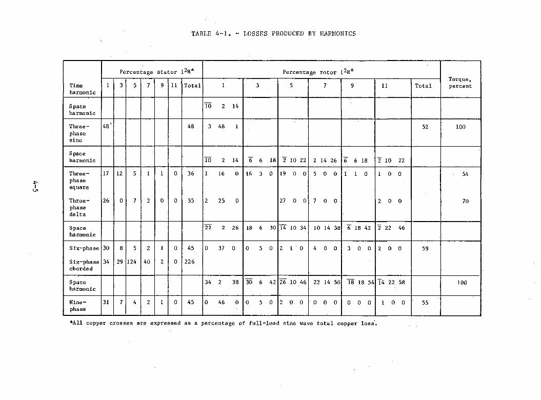
TABLE 4-1. - LOSSES PRODUCED BY HARMONICS
-p-lm
Percentage stator 12R* Percentage rotor 12R*Torque,percentTime
harmonic1 3 5 7 9 11 Total 1 3 5 7 9 11 Total
Spaceharmonic
10 2 14
Three-phasesine
4 8 ' 4 8 3 4 8 1 52 1 0 0
Spaceharmonic T o 2 14 6 6 18 2 1 0 22 2 14 2 6 6 6 18 2 10 22
Three-phasesquare
17 12 5 1 1 0 3 6 1 16 0 16 3 0 19 0 0 5 0 0 1 1 0 1 0 0 54
Three-phasedelta
2 6 0 7 2 0 0 3 5 2 2 5 0 27 0 0 7 0 0. 2 0 0 70
Spacehar-monic
2 2 2 2 6 18 6 3 0 T 4 10 34 10 14 3 8 6 18 4 2 2 2 2 4 6
Six-phase 3 0 8 5 2 1 0 4 5 0 37 0 0 5 0 2 1 0 4 0 0 3 0 0 2 0 0 5 9
Six-phase chorded
34 29 124 4 0 2 0 2 2 6
Spaceharmonic
3 4 2 3 8 3 0 6 4 2 2 6 1 0 4 6 2 2 14 5 0 1 8 18 5 4 1 4 2 2 58 1 0 0
Nine-phase
31 7 4 2 1 0 4 5 0 4 6 0 0 5 0 2 0 0 0 0 0 0 0 0 1 0 0 5 5
*A11 copper crosses are expressed as a percentage of full-load sine wave total copper loss.
If the number of phases is increased, the first lower sidebands will increase in pole-pair number, n, and their winding factor will decrease. If the number of phases is increased from three to six, the 5th and 7th time-harmonics produce lower sideband space-harmonic waves with 28 and 2 0 poles, respectively, which will be small in magnitude compared with those of the corresponding harmonics, n = -2 and +2, in the three-phase motor. Table 4-1 also shows the improvement in copper losses achieved by increasing the number of phases in this machine. The corresponding performance for a nine-phase machine (Q = 18) is also included in Table 4-1.
A further advantage of increasing the number of phases is that the flux density distribution approaches that of a travelling square wave as the number of phases increases. Figure 4-2 shows the airgap flux density distribution for three-, six-, and nine-phase machines supplied with a square-wave voltage, and also shows the case of a three-phase sinusoidal supply. The peak flux density in the six- and nine-phase machines is less than that in the three-phase sinusoidal case and, as a result, the slots can be slightly widened.
The corresponding current waveforms are shown in Figure 4-3. It can be seen that the current wave shapes tend to a square wave plus a magnetizing pulse (to produce the near-square wave of flux density) as the number of phases increases.
Many three-phase double-layer windings are under-pitched or chorded to reduce the space-harmonics produced. A typical example is a six-slot-per-pole winding with the coils pitched five slots (5/6 chorded) to reduce the 5th and 7th harmonics. But care must be taken in case of nonsinusoidal voltage-fed supplies; otherwise, high circulating currents may result, as may be seen by comparing the results in Table 4-1 for a six-phase machine with and without chording. If the winding is 5/6 chorded, the 5th and 7th space harmonics are reduced to 19 and 14 percent of their original values, respectively. The effect of this chording on the equivalent circuit of Figure 4-1(b) is to reduce the effective impedance of the fundamental branch for the 5th and 7th time harmonics. For example, in case of a 5th time-harmonic component of input voltage and considering only the first two terms of the sidebands, the equivalent circuit consists of the fundamental branch of 2 0 poles in series with the first sidebands, with 28 poles and 6 8 poles, since Q = 12. The 20-pole wave will be reduced by the effect of 5/6 chording; therefore, the impedance of this branch will-be reduced. The 5th harmonic current will therefore increase and Table 4-1 shows that the stator copper loss for this design has increased dramatically from that of the fully pitched design. The 5th and 7th harmonic currents are mainly responsible for the increased copper losses, because they have been effectively short-circuited by the reduction in the chording factor.
Another design feature that will reduce losses in inverter-fed traction motors is the reduction of the deep-bar effect in the rotor design, because high-slip space harmonics produced by the inverter output waveforms will otherwise produce high rotor copper losses.
4-6
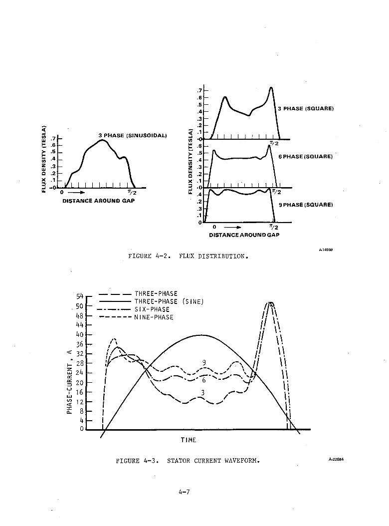
FLU
X D
EN
SIT
Y (
TES
LA)
A-14569
FIGURE 4-2. FLUX DISTRIBUTION.
FIGURE 4-3. STATOR CURRENT WAVEFORM A -2 2 6 8 4
4-7
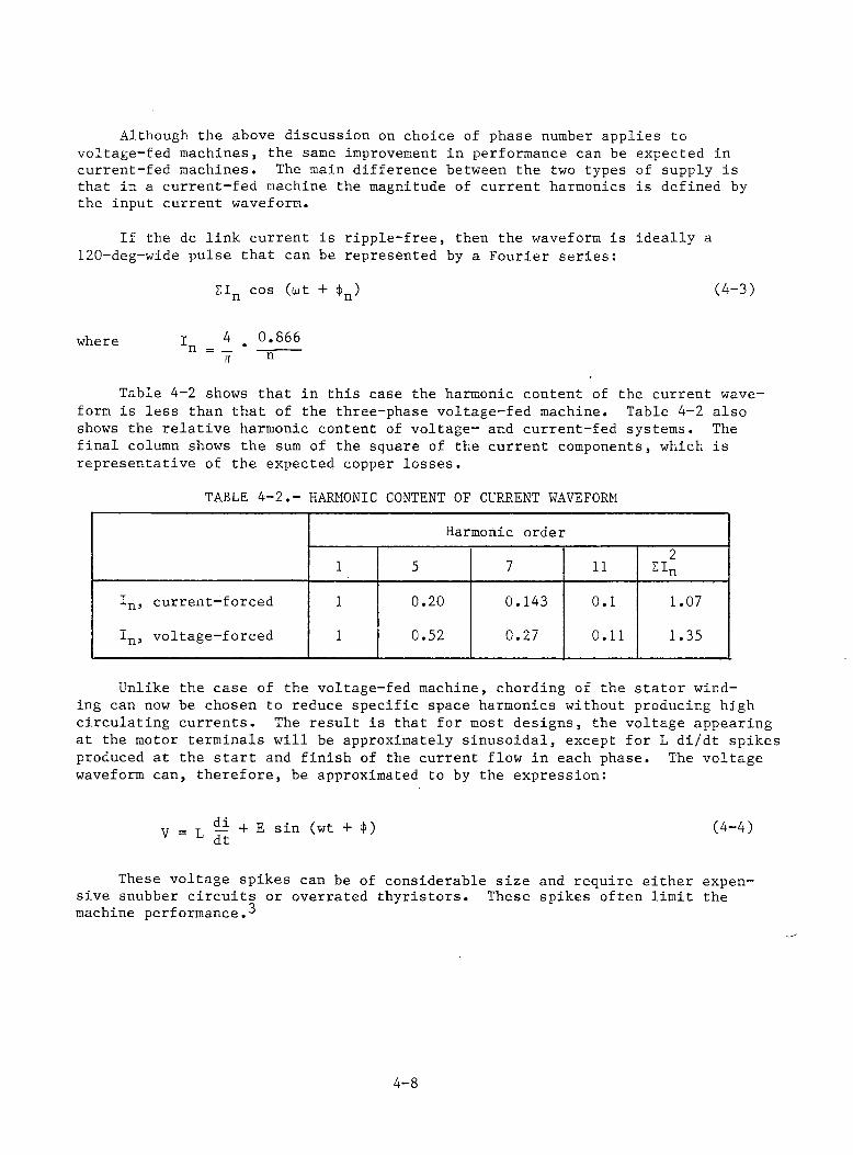
Although the above discussion on choice of phase number applies to voltage-fed machines, the same improvement in performance can be expected in current-fed machines. The main difference between the two types of supply is that in a current-fed machine the magnitude of current harmonics is defined by the input current waveform.
If the dc link current is ripple-free, then the waveform is ideally a 120-deg-wide pulse that can be represented by a Fourier series:
£In cos (tot + <j>n ) (4-3)
where Ir . 0 . 8 6 6~ ~ n
Table 4-2 shows that in this case the harmonic content of the current waveform is less than that of the three-phase voltage-fed machine. Table 4-2 also shows the relative harmonic content of voltage- and current-fed systems. The final column shows the sum of the square of the current components, which is representative of the expected copper losses.
TABLE 4-2.- HARMONIC CONTENT OF CURRENT WAVEFORM
Harmonic order
1 5 7 112
SinIn. current-forced 1 0.20 0.143 0.1 1.07
*n> voltage-forced 1 0.52 0.27 0 . 1 1 1.35
Unlike the case of the voltage-fed machine, chording of the stator winding can now be chosen to reduce specific space harmonics without producing high circulating currents. The result is that for most designs, the voltage appearing at the motor terminals will be approximately sinusoidal, except for L di/dt spikes produced at the start and finish of the current flow in each phase. The voltage waveform can, therefore, be approximated to by the expression:
V — + E sin (wt + <|>) dt (4-4)
These voltage spikes can be of considerable size and require either expensive snubber circuits or overrated thyristors. These spikes often limit the machine performance.3
4-8

REFERENCES
McLean, G., "The Influence of Voltage Time-Harmonics on the Performance of Induction Motors,” Proc. of International Conference on Power Electronics, Nova Dubnica, 1971.Lippo, T., "A d-q Model for Six-Phase Induction Machines," Proc. International Conference on Electrical Machines, Athens, 1980.
4-9
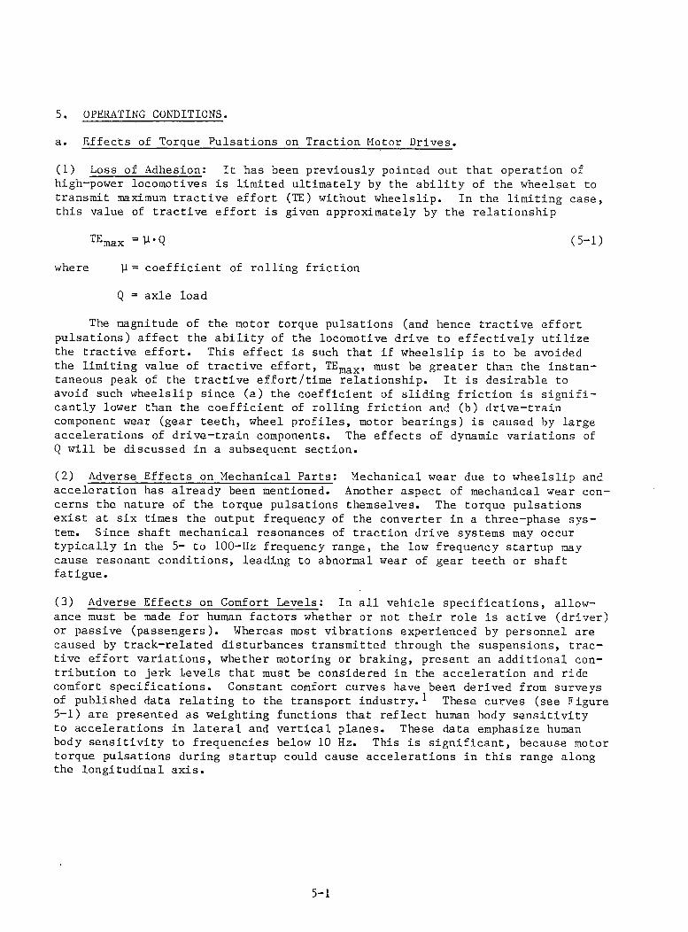
5. OPERATING CONDITIONS.a. Effects of Torque Pulsations on Traction Motor Drives.
(1) Loss of Adhesion: It has been previously pointed out that operation ofhigh-power locomotives is limited ultimately by the ability of the wheelset to transmit maximum tractive effort (IE) without wheelslip. In the limiting case, this value of tractive effort is given approximately by the relationship
^max = U'Q (5-1)where y = coefficient of rolling friction
Q = axle load
The magnitude of the motor torque pulsations (and hence tractive effort pulsations) affect the ability of the locomotive drive to effectively utilize the tractive effort. This effect is such that if wheelslip is to be avoided the limiting value of tractive effort, TEmax, must be greater than the instantaneous peak of the tractive effort/time relationship. It is desirable to avoid such wheelslip since (a) the coefficient of sliding friction is significantly lower than the coefficient of rolling friction and (b) drive-train component wear (gear teeth, wheel profiles, motor bearings) is caused by large accelerations of drive-train components. The effects of dynamic variations of Q will be discussed in a subsequent section.
(2) Adverse Effects on Mechanical Parts: Mechanical wear due to wheelslip andacceleration has already been mentioned. Another aspect of mechanical wear concerns the nature of the torque pulsations themselves. The torque pulsations exist at six times the output frequency of the converter in a three-phase system. Since shaft mechanical resonances of traction drive systems may occur typically in the 5- to 100-Hz frequency range, the low frequency startup may cause resonant conditions, leading to abnormal wear of gear teeth or shaft fatigue.
(3) Adverse Effects on Comfort Levels: In all vehicle specifications, allowance must be made for human factors whether or not their role is active (driver) or passive (passengers). Whereas most vibrations experienced by personnel are caused by track-related disturbances transmitted through the suspensions, tractive effort variations, whether motoring or braking, present an additional contribution to jerk levels that must be considered in the acceleration and ride comfort specifications. Constant comfort curves have been derived from surveys of published data relating to the transport industry.^ These curves (see Figure5-1) are presented as weighting functions that reflect human body sensitivityto accelerations in lateral and vertical planes. These data emphasize human body sensitivity to frequencies below 10 Hz. This is significant, because motor torque pulsations during startup could cause accelerations in this range along the longitudinal axis.
5-1
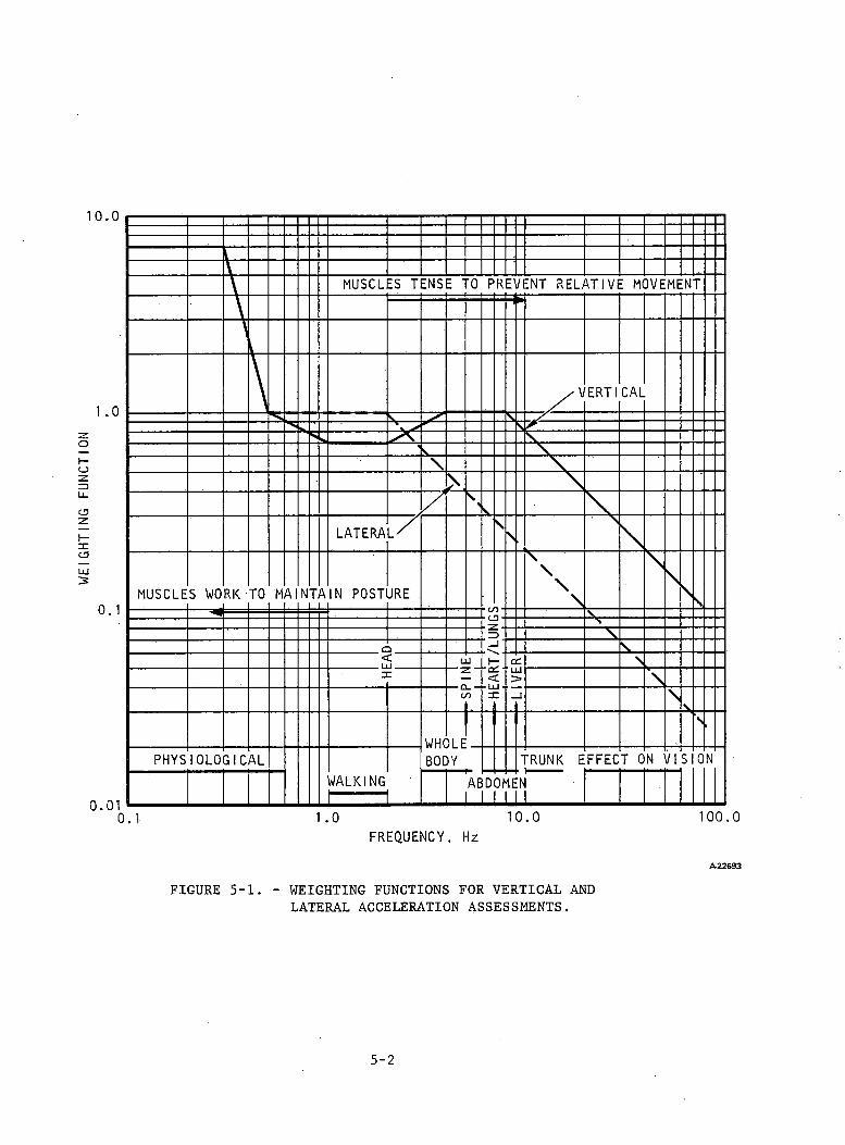
WEI
GHTI
NG
FUNC
TION
FREQUENCY, Hz
A -2 2 6 9 3
FIGURE 5-1. - WEIGHTING FUNCTIONS FOR VERTICAL AND LATERAL ACCELERATION ASSESSMENTS.
5-2
b. Special C o n s iderations
(1) Torque Pulsations: Torque pulsation is a special problem of converter-fedac traction motor drives that is not normally encountered in the commutator-type dc traction motor drive. Torque pulsation can become a major problem if its frequency coincides with one of the resonant frequencies of the mechanical transmission between the traction motor and the driven wheel. These resonant frequencies typically lie between 5 and 100 Hz, and it is at starting and during low-speed operations that a resonance is likely to occur. Much of the energy associated with frequencies at the top end of this resonance band, however, can be absorbed by the mechanical resilience of the drive.
In a three-phase traction motor drive, the major torque pulsation occurs at six times supply frequency. Therefore it would be desirable to start an induction-type traction motor at a frequency that produces torque pulsations above the major resonances. Such a frequency, however, would produce excessive motor copper losses in the traction motor, so that much recent effort has been directed towards reduction of torque pulsations in traction drives through two basic approaches:
(a) Reducing harmonic content in the voltage and current waveforms applied to the traction motor
(b) Increasing the number of phases supplying the traction motor
The fundamental reason for torque pulsations in a converter-fed ac traction motor is that the current and/or voltage waveforms are nonsinusoidal.This in itself, however, is not sufficient reason to produce torque pulsations because commutator-type dc motors, which can be considered as a special multiphase ac machine, do not exhibit significant torque pulsations even though the current flowing in each coil of their armature windings is virtually a square wave and the voltage across each coil has a nonsinusoidal wave shape. Since in dc machines the number of effective phases is usually large (equal to the number of commutator segments per pole) a corresponding increase in the number of phases of converter-fed ac machines above the conventional three-phase arrangement is an effective means of reducing the torque p u l s a t i o n . 3
An alternative approach is to retain the three-phase supply but reduce the harmonic content of the supply w a v e f o r m s . T h i s last approach is to produce a system that approximates as nearly as possible to a standard three-phase sinusoidal supply feeding a standard three-phase motor, the variable speed being achieved by varying the frequency of the supply. The latter method is probably the most obvious and will be considered first.
(2) Reduction of Harmonic Content in Supply Waveform: An ideal three-phasewinding would produce pure sinusoidal flux-density and current-density travelling waves in the airgap of the traction motor. The two practical effects that prevent this are: (a) space-harmonic waves produced by the slotted nature ofthe windings and (b) time-harmonic waves produced by the time harmonics present in the current waveforms supplying the winding.
5-3
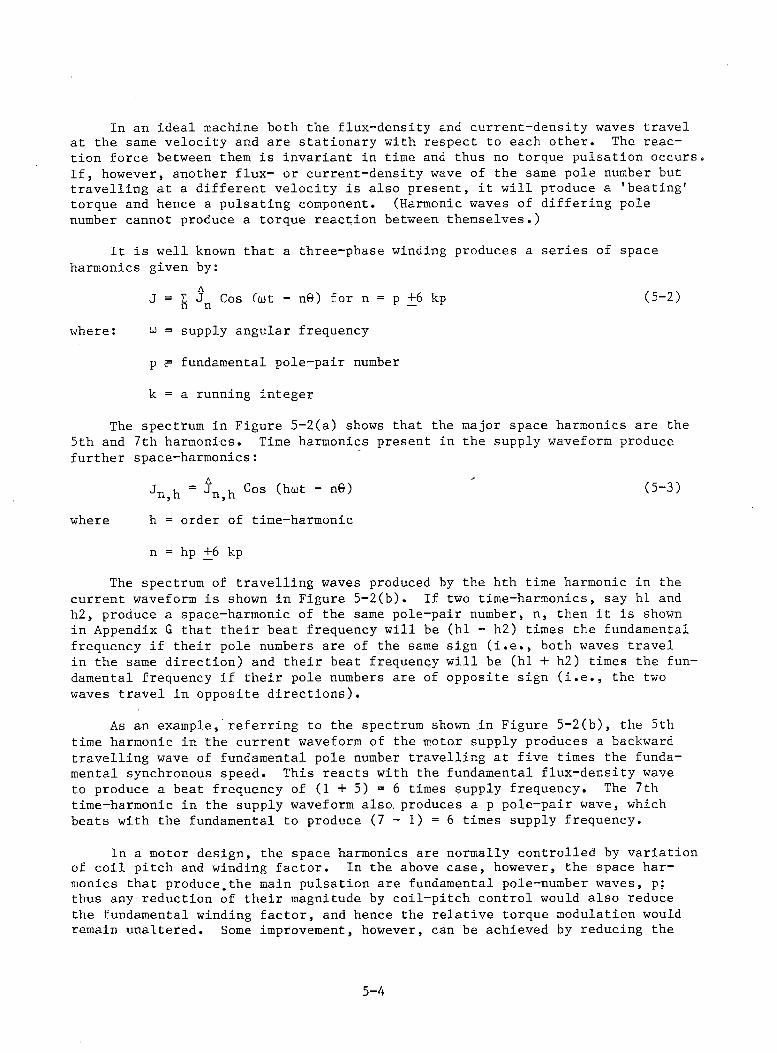
In an ideal machine both the flux-density and current-density waves travel at the same velocity and are stationary with respect to each other. The reaction force between them is invariant in time and thus no torque pulsation occurs. If, however, another flux- or current-density wave of the same pole number but travelling at a different velocity is also present, it will produce a 'beating' torque and hence a pulsating component. (Harmonic waves of differing pole number cannot produce a torque reaction between themselves.)
It is well known that a three-phase winding produces a series of space harmonics given by:
J = E J Cos Cut - n0) for n = p +6 kp (5-2)
where: u = supply angular frequency
p >= fundamental pole-pair number
k = a running integer
The spectrum in Figure 5-2(a) shows that the major space harmonics are the 5th and 7th harmonics. Time harmonics present in the supply waveform produce further space-harmonics:
Jn,h = ^n,h Cos (haJt " n0) (5_3)where h = order of time-harmonic
n = hp +6 kp
The spectrum of travelling waves produced by the hth time harmonic in the current waveform is shown in Figure 5-2(b). If two time-harmonics, say hi and h2, produce a space-harmonic of the same pole-pair number, n, then it is shown in Appendix G that their beat frequency will be (hi - h2) times the fundamental frequency if their pole numbers are of the same sign (i.e., both waves travel in the same direction) and their beat frequency will be (hi + h2) times the fundamental frequency if their pole numbers are of opposite sign (i.e., the two waves travel in opposite directions).
As an example, referring to the spectrum shown in Figure 5-2(b), the 5th time harmonic in the current waveform of the motor supply produces a backward travelling wave of fundamental pole number travelling at five times the fundamental synchronous speed. This reacts with the fundamental flux-density wave to produce a beat frequency of ( 1 + 5 ) = 6 times supply frequency. The 7th time-harmonic in the supply waveform also, produces a p pole-pair wave, which beats with the fundamental to produce (7 - 1) = 6 times supply frequency.
In a motor design, the space harmonics are normally controlled by variation of coil pitch and winding factor. In the above case, however, the space harmonics that produce.the main pulsation are fundamental pole-number waves, p; thus any reduction of their magnitude by coil-pitch control would also reduce the fundamental winding factor, and hence the relative torque modulation would remain unaltered. Some improvement, however, can be achieved by reducing the
5-4
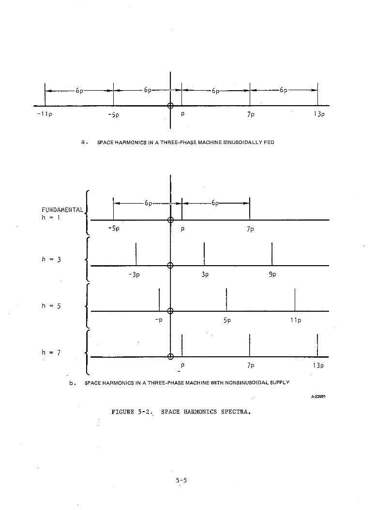
a . SPACE HARMONICS IN A THREE-PHASE MACHINE SINUSOIDALLY FED
FUNDAMENTAL h = 1
h = 3
h = 5
h = 7
b.
A -2 2 69 1
FIGURE 5-2. SPACE HARMONICS SPECTRA.
5-5

magnitude of the other pole-number waves (e.g., the 5p and 7p pole pairs), though this can produce increased harmonic currents in the stator winding of voltage-fed traction motors. If, for example, the 5th space-harmonic is reduced by choosing an appropriate coil pitch, the 5p pole-pair wave produced by the 5th time harmonic (travelling at fundamental synchronous speed) is also reduced, which, in turn, would reduce the input impedance of the motor that corresponds to 5 times the supply frequency. The result would be a high 5th harmonic stator current component if the winding is voltage-fed.-
In general, in a three-phase machine only a limited reduction in torque pulsation can be achieved in a three-phase machine by the winding design. For this reason most attempts to reduce torque pulsation in three-phase systems have been aimed at improving applied waveform shape.
(3) Voltage-fed Systems: Pulse-width modulation (PWM) with various switchingstrategies has been used to control harmonic content of voltage waveforms.^Often a relatively simple switching sequence can produce appreciable improvement in performance.^ A more elaborate control, however, can be achieved with microprocessors, using a different number of pulses per cycle as frequency changes. A fixed number of harmonics can be eliminated and, at the same time, the fundamental amplitude can be controlled by selecting a suitable number of switchings per cycle and positioning them appropriately. Alternative strategies that aim to minimize the total RMS distortion are also known.
(4) Current-fed Systems: In current-fed systems, such as those shown in Figure5-3, a modulated current waveform can be obtained by transferring current pulses from one phase to another while maintaining the net current in the dc link constant. This method typically eliminates some current harmonics and reduces torque pulsation. Figure 5-3(a) shows the measured^ torque pulsation of a current-fed inverter drive with no current modulation. At 5-Hz supply frequency and at the corresponding torque pulsation a resonance of the drive train occurs. The measured resonant torque pulsation peak is approximately equal to the rated torque. Figure 5-3(b) shows the improvement that can be achieved by choosing a pulse combination that eliminates the 5th, 7th, and 11th harmonics. It can be seen that the pulse shape has been chosen to decrease the 6-times term but has increased the 18-times term.
Current pulse modulation is, therefore, an effective means of torque pulsation control. There is a limit, however, in the achievable reduction since the switching itself produces higher-order harmonics with an associated increase in copper and iron loss. High switching rates also produce excessive inverter losses, which increase with frequency, and therefore the control system usually varies the number of pulses per cycle as a function of frequency, as shown in Figure 5-4.
An important consideration of this otherwise attractive system includes the cost of forced commutation in addition to the front-end current control that is required in the form of a phase-delay converter or chopper. Most systems having this type of current-fed inverter use some type of forced-commutated control to achieve a reasonable input power factor when operating from an ac power supply. Figure 5-5 shows, for a typical input converter circuit, the input
5-6
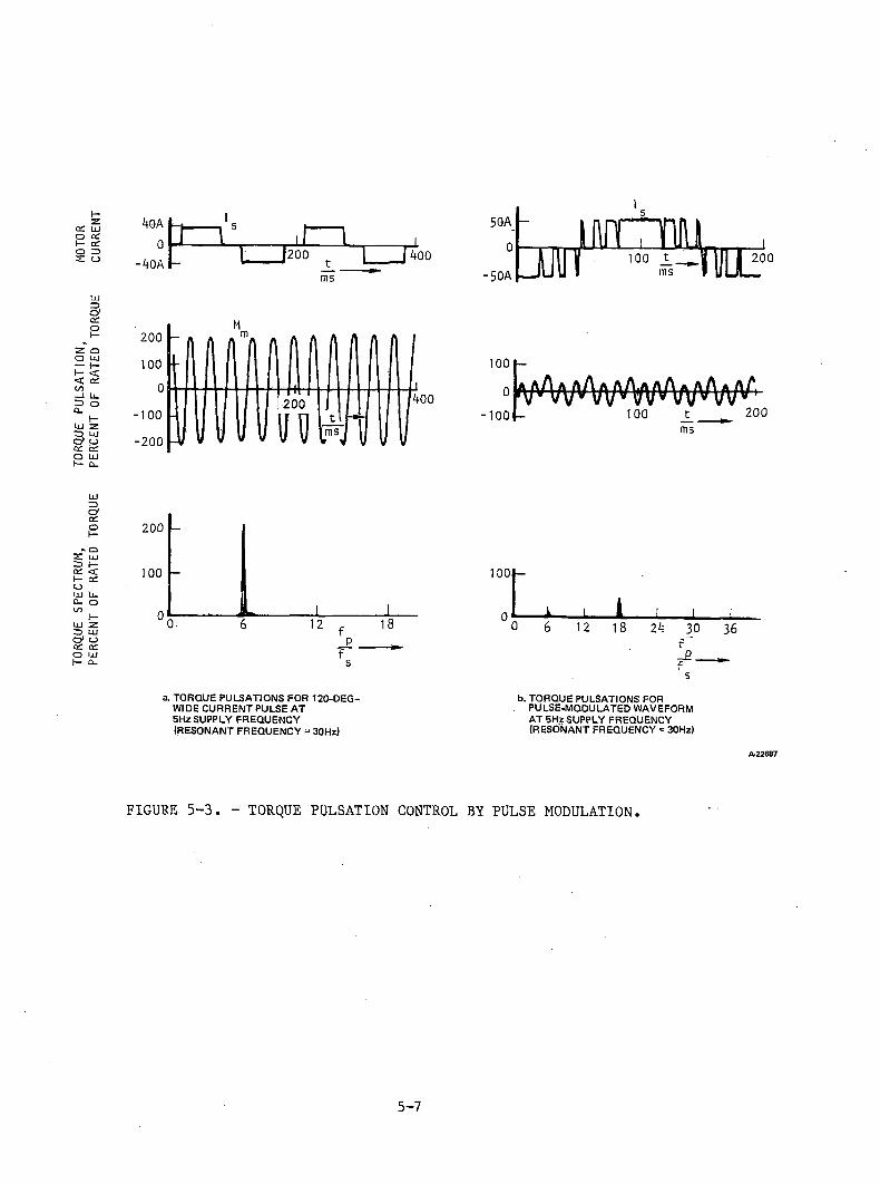
TOR
QU
E
SP
EC
TR
UM
, TO
RQ
UE
P
UL
SA
TIO
N,
MO
TOR
PE
RC
EN
T
OF
R
ATE
D
TOR
QU
E
PE
RC
EN
T
OF
R
AT
ED
TO
RQ
UE
C
UR
RE
NT
4 0 A I - ,
0- b O A -
l____>200 t 4 0 0
ms
50A0
- 5 0 A JUU f
i
2001000
-100-200
! 200n ms
Mfoo
1001-
^/v/ V \ M a M / \ A A a A A a / ^ '-100 - 100 200ms
1001-
i- i 16 12 18J___l___L24 30 36
f_e___fa. TORQUE PULSATIONS FOR 120-DEG-
WIDE CURRENT PULSE AT 5Hz SUPPLY FREQUENCY (RESONANT FREQUENCY = 30Hz)
b. TORQUE PULSATIONS FOR PULSE-MODULATED WAVEFORM AT SHzSUPPLY FREQUENCY (RESONANT FREQUENCY = 30Hz)
A-22687
FIGURE 5-3. - TORQUE PULSATION CONTROL BY PULSE MODULATION.
5-7
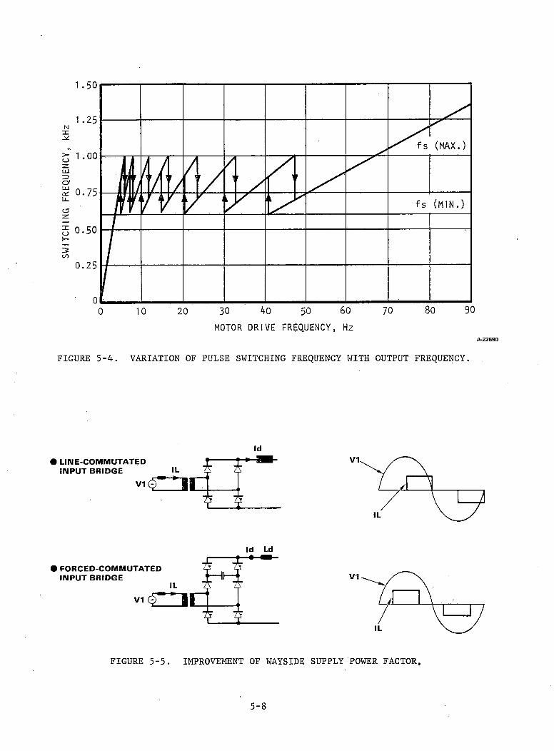
FIGURE 5-4. VARIATION OF PULSE SWITCHING FREQUENCY WITH OUTPUT FREQUENCY.
Id Ld
FIGURE 5-5. IMPROVEMENT OF WAYSIDE SUPPLY POWER FACTOR.
5-8
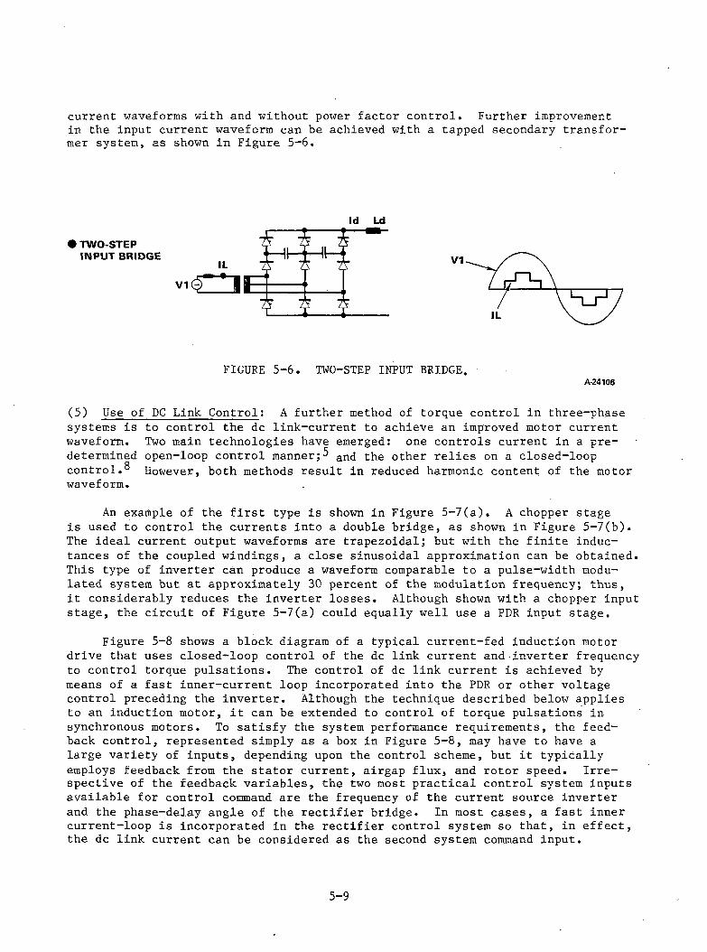
current waveforms with and without power factor control. Further improvement in the input current waveform can be achieved with a tapped secondary transformer system, as shown in Figure 5-6.
FIGURE 5-6. TWO-STEP INPUT BRIDGE.A-24106
(5) Use of DC Link Control; A further method of torque control in three-phase systems is to control the dc link-current to achieve an improved motor current waveform. Two main technologies have emerged: one controls current in a predetermined open-loop control m a n n e r an<j the other relies on a closed-loop control.® However, both methods result in reduced harmonic content of the motor waveform.
An example of the first type is shown in Figure 5-7(a). A chopper stage is used to control the currents into a double bridge, as shown in Figure 5-7(b). The ideal current output waveforms are trapezoidal; but with the finite inductances of the coupled windings, a close sinusoidal approximation can be obtained. This type of inverter can produce a waveform comparable to a pulse-width modulated system but at approximately 30 percent of the modulation frequency; thus, it considerably reduces the inverter losses. Although shown with a chopper input stage, the circuit of Figure 5-7(a) could equally well use a PDR input stage.
Figure 5-8 shows a block diagram of a typical current-fed induction motor drive that uses closed-loop control of the dc link current and inverter frequency to control torque pulsations. The control of dc link current is achieved by means of a fast inner-current loop incorporated into the PDR or other voltage control preceding the inverter. Although the technique described below applies to an induction motor, it can be extended to control of torque pulsations in synchronous motors. To satisfy the system performance requirements, the feedback control, represented simply as a box in Figure 5-8, may have to have a large variety of inputs, depending upon the control scheme, but it typically employs feedback from the stator current, airgap flux, and rotor speed. Irrespective of the feedback variables, the two most practical control system inputs available for control command are the frequency of the current source inverter and the phase-delay angle of the rectifier bridge. In most cases, a fast inner current-loop is incorporated in the rectifier control system so that, in effect, the dc link current can be considered as the second system command input.
5-9
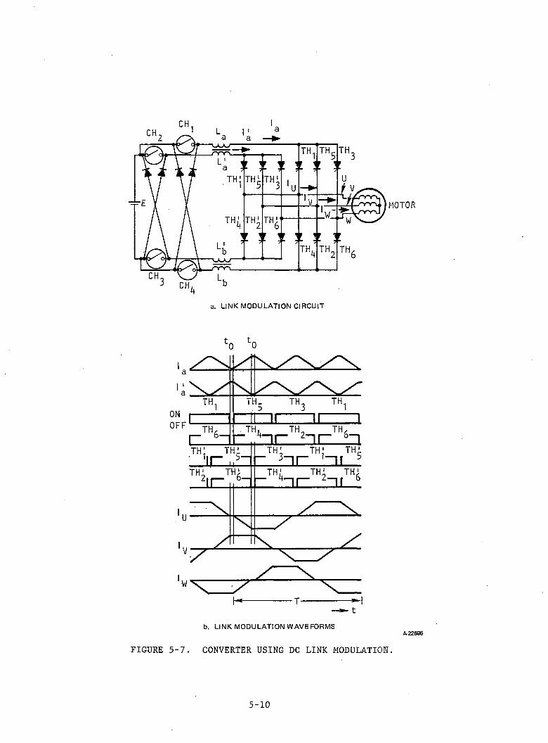
MOTOR
lo fco
■T-
b . L IN K M O D U L A T IO N W A V E F O R M S
FIGURE 5-7. CONVERTER USING DC LINK MODULATION.A -2 2 6 9 5
5-10
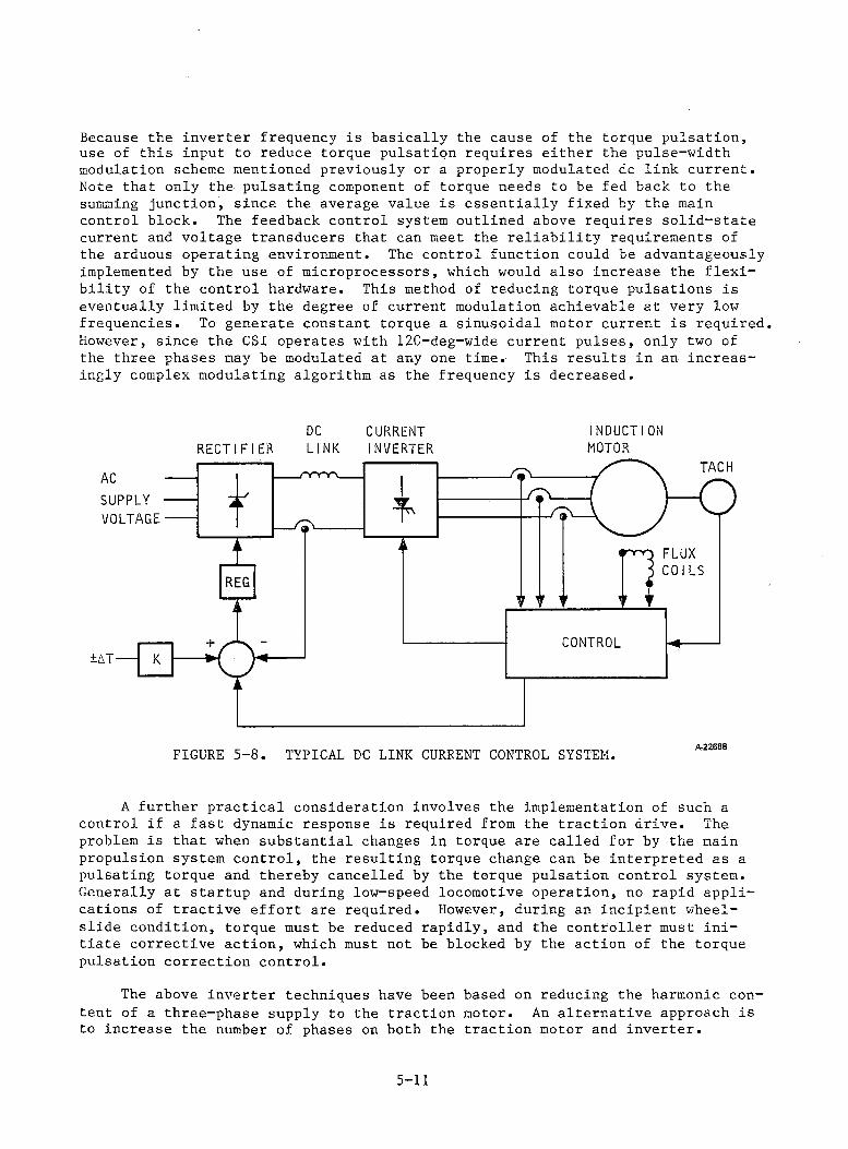
Because the inverter frequency is basically the cause of the torque pulsation, use of this input to reduce torque pulsation requires either the pulse-width modulation scheme mentioned previously or a properly modulated dc link current. Note that only the pulsating component of torque needs to be fed back to the summing junction, since the average value is essentially fixed by the main control block. The feedback control system outlined above requires solid-state current and voltage transducers that can meet the reliability requirements of the arduous operating environment. The control function could be advantageously implemented by the use of microprocessors, which would also increase the flexibility of the control hardware. This method of reducing torque pulsations is eventually limited by the degree of current modulation achievable at very low frequencies. To generate constant torque a sinusoidal motor current is required However, since the CSI operates with 120-deg-wide current pulses, only two of the three phases may be modulated at any one time. This results in an increasingly complex modulating algorithm as the frequency is decreased.
DC CURRENT INDUCTIONRECTIFIER LINK INVERTER MOTOR
FIGURE 5-8. TYPICAL DC LINK CURRENT CONTROL SYSTEM. Ar22688
A further practical consideration involves the implementation of such a control if a fast dynamic response is required from the traction drive. The problem is that when substantial changes in torque are called for by the main propulsion system control, the resulting torque change can be interpreted as a pulsating torque and thereby cancelled by the torque pulsation control system. Generally at startup and during low-speed locomotive operation, no rapid applications of tractive effort are required. However, during an incipient wheel- slide condition, torque must be reduced rapidly, and the controller must initiate corrective action, which must not be blocked by the action of the torque pulsation correction control.
The above inverter techniques have been based on reducing the harmonic content of a three-phase supply to the traction motor. An alternative approach is to increase the number of phases on both the traction motor and inverter.
5-11
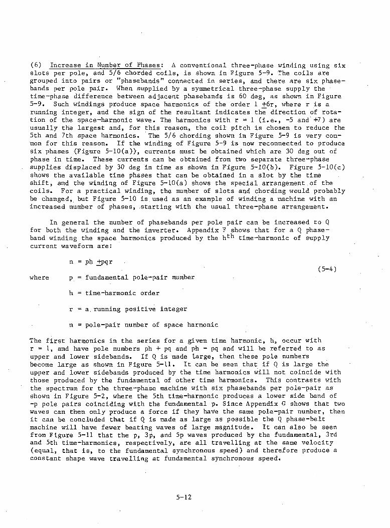
(6) Increase in Number of Phases: A conventional three-phase winding using sixslots per pole, and 5/6 chorded coils, is shown in Figure 5-9. The coils are grouped into pairs or "phasebands" connected in series, and there are six phase- bands per pole pair. When supplied by a symmetrical three-phase supply the time-phase difference between adjacent phasebands is 60 deg, as shown in Figure 5-9. Such windings produce space harmonics of the order 1 +6r, where r is a running integer, and the sign of the resultant indicates the direction of rotation of the space-harmonic wave. The harmonics with r = 1 (i.e., -5 and +7) are usually the largest and, for this reason, the coil pitch is chosen to reduce the 5th and 7th space harmonics. The 5/6 chording shown in Figure 5-9 is very common for this reason. If the winding of Figure 5-9 is now reconnected to produce six phases (Figure 5-10(a)), currents must be obtained which are 30 deg out of phase in time. These currents can be obtained from two separate three-phase supplies displaced by 30 deg in time as shown in Figure 5-10(b). Figure 5-10(c) shows the available time phases that can be obtained in a slot by the time shift, and the winding of Figure 5-10(a) shows the special arrangement of the coils. For a practical winding, the number of slots and chording would probably be changed, but Figure 5-10 is,used as an example of winding a machine with an increased number of phases, starting with the usual three-phase arrangement.
In general the number of phasebands per pole pair can be increased to Q for both the winding and the inverter. Appendix F shows that for a Q phase- band winding the space harmonics produced by the h*-*1 time-harmonic of supply current waveform are:
n = ph +pqrwhere p = fundamental pole-pair number
h = time-harmonic order r = a,running positive integer n = pole-pair number of space harmonic
(5-4)
The first harmonics in the series for a given time harmonic, h, occur with r = 1, and have pole numbers ph + pq and ph - pq and will be referred to as upper and lower sidebands. If Q is made large, then these pole numbers become large as shown in Figure 5—11. It can be seen that if Q is large the upper and lower sidebands produced by the time harmonics will not coincide with those produced by the fundamental of other time harmonics. This contrasts with the spectrum for the three-phase machine with Six phasebands per pole-pair as shown in Figure 5-2, where the 5th time-harmonic produces a lower side band of -p pole pairs coinciding with the fundamental p. Since Appendix G shows that two waves can then only produce a force if they have the same pole-pair number, then it can be concluded that if Q is made as large as possible the Q phase-belt machine will have fewer beating waves of large magnitude. It can also be seen from Figure 5-11 that the p, 3p, and 5p waves produced by the fundamental, 3rd and 5th time-harmonics, respectively, are all travelling at the same velocity (equal, that is, to the fundamental synchronous speed) and therefore produce a constant shape wave travelling at fundamental synchronous speed.
5-12
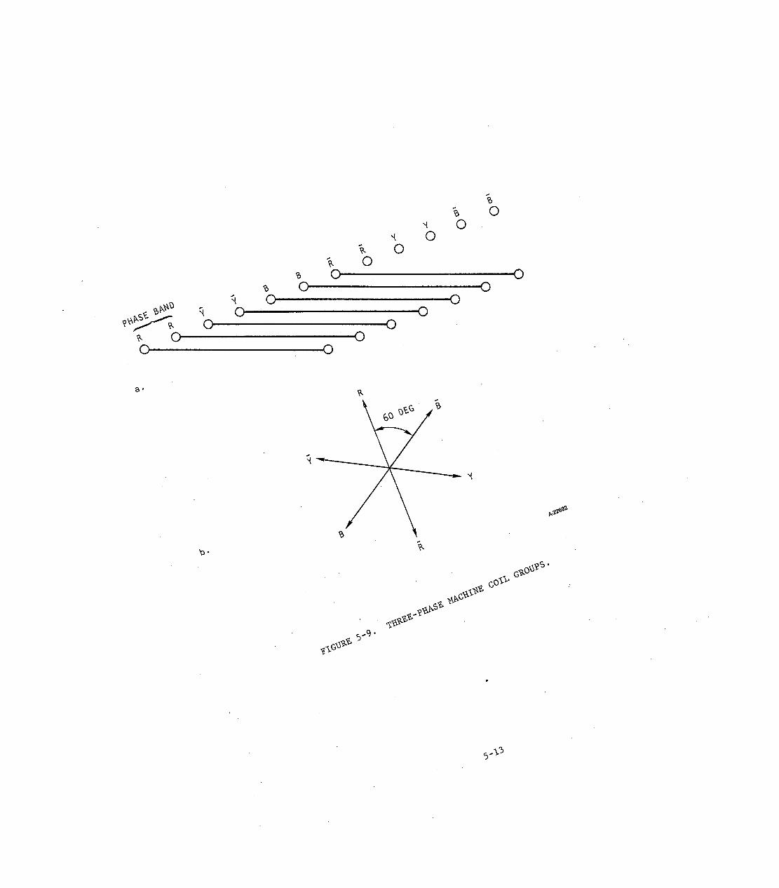
6
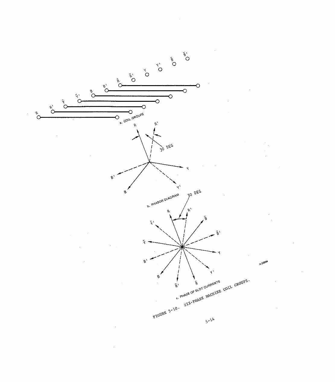
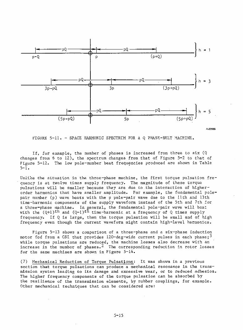
h = 1
A-22685
FIGURE 5-11. - SPACE HARMONIC SPECTRUM FOR A Q PHASE-BELT MACHINE.
If, for example, the number of phases is increased from three to six (Q changes from 6 to 12), the spectrum changes from that of Figure 5-2 to that of Figure 5-12. The low pole-number beat frequencies produced are shown in Table5-1.
Unlike the situation in the three-phase machine, the first torque pulsation frequency is at twelve times supply frequency. The magnitude of these torque pulsations will be smaller because they are due to the interaction of higher- order harmonics that have smaller amplitude. For example, the fundamental pole- pair number (p) wave beats with the p pole-pair wave due to the 11th and 13th time-harmonic components of the supply waveform instead of the 5th and 7th for a three-phase machine. In general, the fundamental pole-pair wave will beat with the (Q+l)t'1 and (Q—1)t“ time-harmonic at a frequency of Q times supply frequency. If Q is large, then the torque pulsation will be small and of high frequency even though the current waveform might contain high-level harmonics.
Figure 5-13 shows a comparison of a three-phase and a six-phase induction motor fed from a CSI that provides 120-deg-wide current pulses in each phase while torque pulsations are reduced, the machine losses also decrease with an increase in the number of phases.^ The corresponding reduction in rotor losses for the same machines are shown in Figure 5-14.
(7) Mechanical Reduction of Torque Pulsations: It was shown in a previoussection that torque pulsations can produce a mechanical resonance in the transmission system leading to its damage and excessive wear, or to reduced adhesion. The higher frequency components of the torque pulsation can be absorbed by the resilience of the transmission elements, by rubber couplings, for example. Other mechanical techniques that can be considered are:
5-15
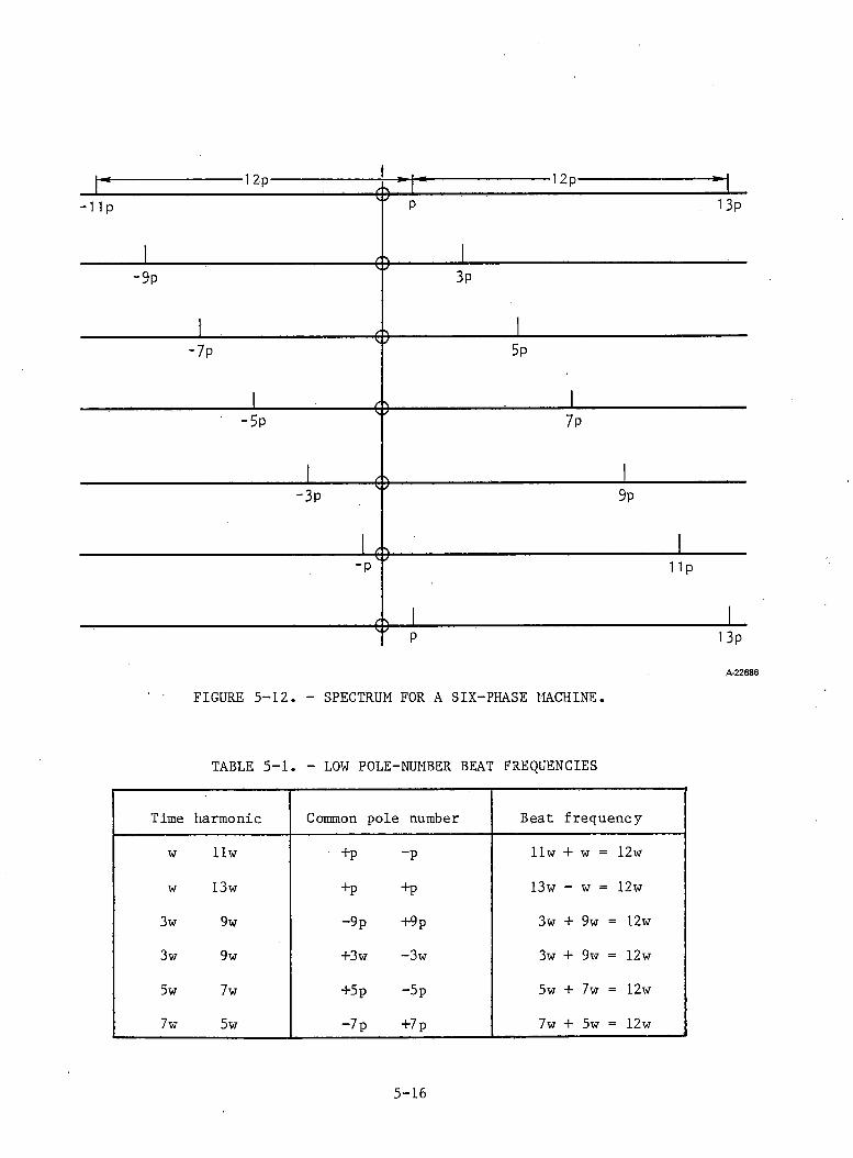
-12p-
■1 I P
-12p-
13P
•9p 3p
-O
■O
- 7 p 5p
•5p
■O
7 p
- 3 p
■O-
9p
-O
U p
13PA-22686
FIGURE 5-12. - SPECTRUM FOR A SIX-PHASE MACHINE.
TABLE 5-1. - LOW POLE-NUMBER BEAT FREQUENCIES
Time harmonic Common pole number Beat frequency
w llw +P “P llw + w = 12w
w 13w +P +P 13w - w = 12w
3w 9w -9p +9p 3w + 9w = 12w
3w 9w +3w -3w 3w + 9w = 12w
5w 7w +5p -5p 5w + 7w = 12w
7w 5w “7 P +7p 7w + 5w = 12w
5-16
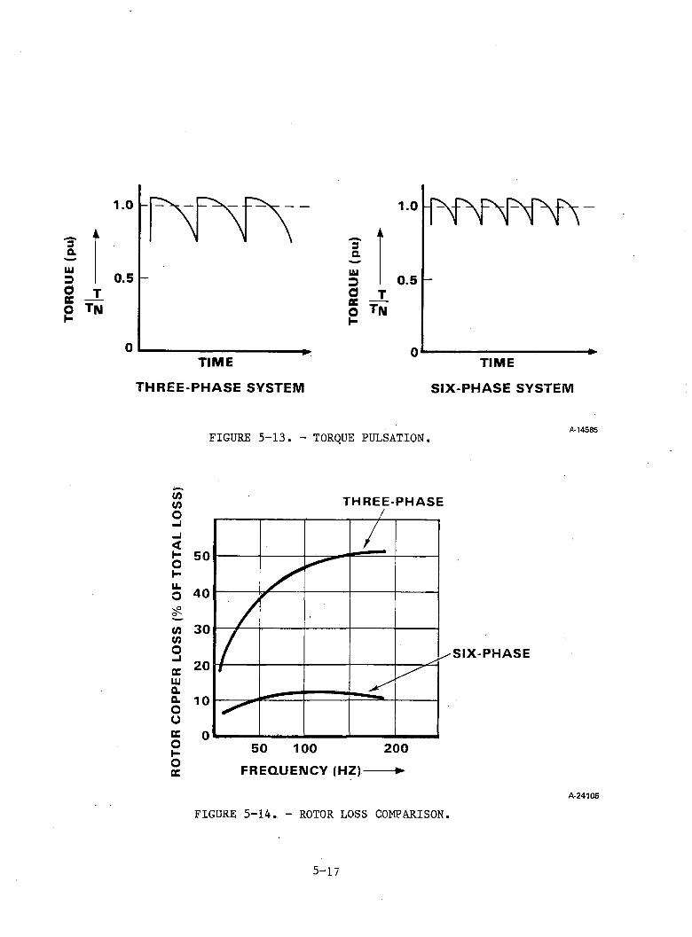
TOR
QU
E (p
u)
THREE-PHASE SYSTEM
3auiDaceOH
SIX-PHASE SYSTEM
A-14585FIGURE 5-13. - TORQUE PULSATION.
THREE-PHASE
SIX-PHASE
FIGURE 5-14. - ROTOR LOSS COMPARISON.A-24105
5-17
(a) Increasing Inertia of Motor Rotor/Shaft. Figure 5-15 shows a simplified model of the basic mechanical components of the transmission. Inertia of the motor/shaft may be increased by adding a flywheel. This is an impractical solution because the mass of the flywheel is related to the frequency of rotation for a given torque pulsation. Therefore, at very low frequencies the size of the required flywheel, to achieve a given attenuation in torque pulsation, tends to be very large.
(b) Fluid Flywheel. A fluid coupling interspersed between the motor and the transmission is capable of providing a smooth drive. An additional feature of the coupling is that the stalled torque increases with the square of the engine speed. Use of a fluid flywheel during starting, however, would reduce torque pulsations transmitted to the driven axle by: (1) enabling maximum torque to be transmitted to the driven axles at standstill with the traction motor running at only 10 to 20 percent of full speed, and (2) permitting constant torque to be realized over a wide speed range, though at the expense of efficiency. The cost and loss of efficiency with the fluid flywheel at very low speeds is to be traded off against the improved starting performance. '
(c) Torque Converter. In place of the fluid flywheel, a torque converter could also be utilized in this application. The increased torque at starting would be of additional benefit in compensating for torque pulsations at the input shaft. However, efficiency above the design point is consistently only 90 to 92 percent, which may exact too heavy a penalty over the entire operating range.
5-18
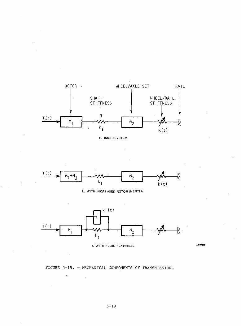
ROTOR WHEEL/AXLE SET RAIL
SHAFTSTIFFNESS
T.(t)
WHEEL/RAIL STIFFNESS
- w vk1
y h -
k ( t )
a . BASIC SYSTEM
T (t) m 1+m3 -A/W
k1- y & < -
k ( t )
b. WITH INCREASED ROTOR IN ER TIA
T(t) □k 1 (t)
M A A r
k1- y / h -
c. WITH FLUID FLYWHEEL
FIGURE 5-15. - MECHANICAL COMPONENTS OF TRANSMISSION.
A-22689
5-19
REFERENCES
1. Draft International Standard ISO/DIS 2631, April 1972.2. McLean, G.W., Performance and Design of Induction Motors with Square-Wave
Excitation," Proc. I.E.E., Vol. 116, No. 8, August 1969.3. Anderson, E., "On the Performance of Inverter-Fed Induction Motor with
Six Phases," Proc. I.C.E.F., Athens, 1980.4. Lineau, W., "Torque Oscillations in Traction Drives with Current-Fed
Asynchronous Machines," I.E.E. Conference on Electrical Variable-Speed Drives, 1979, Pub. No. 179.
5. Chin, T.C., "A Coupled-Reactor-Commutating Sinusoidal-Wave Inverter," Proceedings I.E.E.E., Vol. IA-16, No. 1, 1980.
6. Murphy, J.M.D., "An Analysis of Induction Motor Performance with Optimum PWM Waveforms," Proc. I.C.E.M., Athens, 1980, Part 2, pp. 642-655.
7. Hodkinson, R.L., "25 KVA Precision AC Drive," I.E.E. Conference on Variable-Speed Drives, Pub. No. 179, pp. 74-77.
8. Lipo, T.A: "Analysis and Control of Torque Pulsations in Current-Fed Induction Motor Drives," Electric Machines and Electromechanics, Vol. 3, 1979, pp. 357-368.
5-20
6. LOCOMOTIVE TRACTIONa. Available Adhesion. This subsection examines the utilization of available adhesion with ac and dc locomotives and identifies the improvements required to achieve maximum tractive effort at the wheel/rail interface. The following subjects will be briefly discussed:
(1) Weight transfer between adjacent wheelsets(2) Effect of motor controller on available adhesion(3) Effect of torque pulsations(4) Effect of paralleling traction motors(5) Effect of motor characteristics on wheelslip(6) Effect of axle load fluctuations and electromechanical transients
(1) Weight Transfer Between Adjacent Wheelsets: When a locomotive applies tractive effort to the rails, equilibrium conditions require that forces and couples be generated to cancel those resulting from application of the tractive effort. The net effect is to reduce the actual load on the leading axle of each truck and to increase that in the trailing axle. The sum of all axle loads, naturally, remains constant.
Weight transfer depends on factors such as truck attachment, motor arrangement, etc.; Figure 6-1 shows a typical weight transfer characteristic of a Co-Co locomotive in the motoring mode. When electric braking is applied, the load distribution of Figure 6-1 is reversed. Although the average adhesion, i.e., tractive effort divided by locomotive weight, is 27 percent, the effective adhesion with a tractive effort of 100,000 lb varies between 22.5 percent and 34.3 percent as a result of weight transfer.
The total weight transfer can be divided into three components: (a) motortorque reaction, (b) truck reaction, and (c) chassis reaction. A motor torque reaction not directly cancelable is characteristic of trucks with three or more axles and nose-suspended motors, until very recently the only type used in American designs.
The second reaction is caused by the fact that the points of application of the tractive effort from the axles to the truck and from the truck to the frame do not lie in the same horizontal plane. This reaction is proportional to the ratio h/1, where h is the height over the rail of the point of application of the tractive-effort reaction to the frame and 1 is the truck wheelbase.
An arrangement that reduces the h/1 ratio is the "traction through low bars" method universally used in Europe. The tractive-effort reaction is transmitted from the truck to the locomotive frame by bars inclined so that their axes meet, as nearly as possible, at rail height. In this way, the weight transfer characteristics of the locomotive may be improved by mechanical means. Such arrangement involves a major truck design effort.
6-1
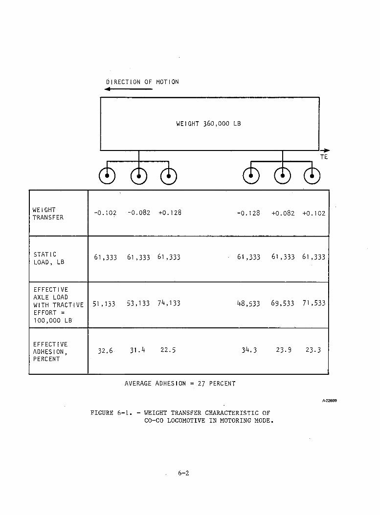
DIRECTION OF MOTION ◄------------------------
0 0 0 © 0 ©WEIGHTTRANSFER - 0 . 1 0 2 - 0 . 0 8 2 + 0 . 1 2 8 - 0 . 1 2 8 + 0 . 0 8 2 + 0 . 1 0 2
STATIC LOAD, LB 61 ,3 33 61 ,3 33 6 1 , 3 3 3 6 1 , 3 3 3 6 1 , 3 3 3 61 , 3 3 3
EFFECTIVE AXLE LOAD WITH TRACTIVE EFFORT = 1 0 0 , 0 0 0 LB
5 1 , 1 3 3 5 3 , 1 3 3 7 4 , 1 3 3 4 8 , 5 3 3 6 9 , 5 3 3 71 , 5 3 3
EFFECTIVEADHESION,PERCENT
3 2 . 6 3 1 . 4 2 2 . 5 3 4 . 3 2 3 - 9 2 3 - 3
AVERAGE ADHESION = 27 PERCENT
A -2 2 6 8 0
FIGURE 6-1. - WEIGHT TRANSFER CHARACTERISTIC OF CO-CO LOCOMOTIVE IN MOTORING MODE.
6-2
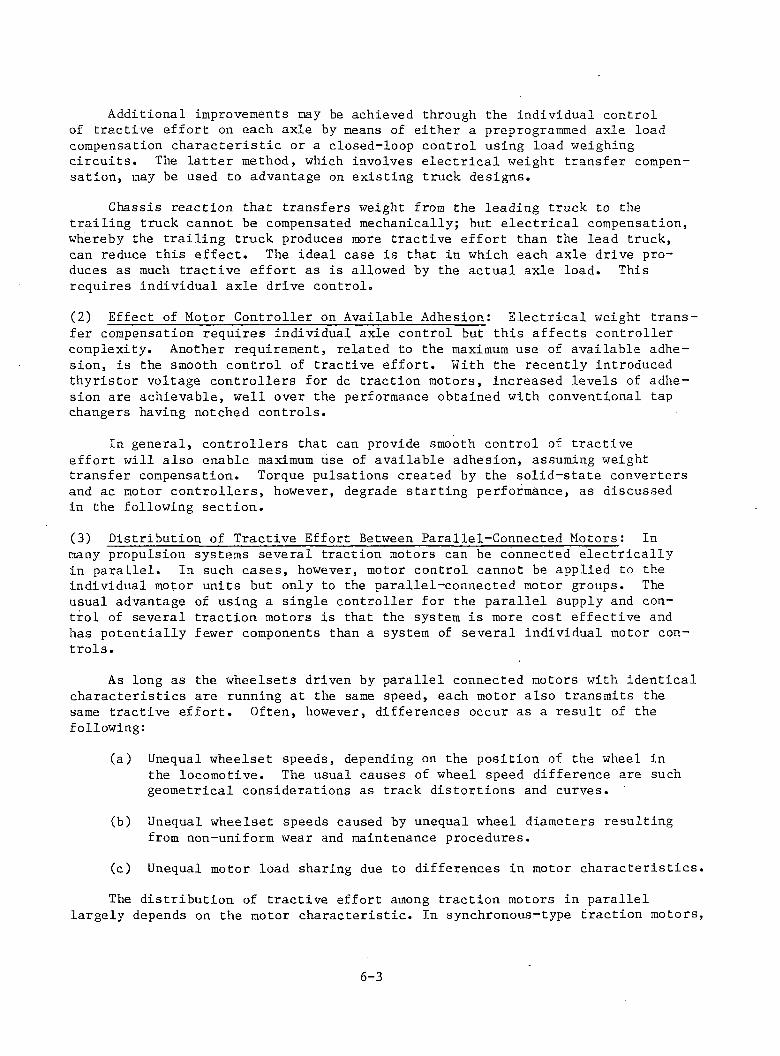
Additional improvements may be achieved through the individual control of tractive effort on each axle by means of either a preprogrammed axle load compensation characteristic or a closed-loop control using load weighing circuits. The latter method, which involves electrical weight transfer compensation, may be used to advantage on existing truck designs.
Chassis reaction that transfers weight from the leading truck to the trailing truck cannot be compensated mechanically; but electrical compensation, whereby the trailing truck produces more tractive effort than the lead truck, can reduce this effect. The ideal case is that in which each axle drive produces as much tractive effort as is allowed by the actual axle load. This requires individual axle drive control.(2) Effect of Motor Controller on Available Adhesion: Electrical weight transfer compensation requires individual axle control but this affects controller complexity. Another requirement, related to the maximum use of available adhesion, is the smooth control of tractive effort. With the recently introduced thyristor voltage controllers for dc traction motors, increased levels of adhesion are achievable, well over the performance obtained with conventional tap changers having notched controls.
In general, controllers that can provide smooth control of tractive effort will also enable maximum use of available adhesion, assuming weight transfer compensation. Torque pulsations created by the solid-state converters and ac motor controllers, however, degrade starting performance, as discussed in the following section.(3) Distribution of Tractive Effort Between Parallel-Connected Motors: Inmany propulsion systems several traction motors can be connected electrically in parallel. In such cases, however, motor control cannot be applied to the individual motor units but only to the parallel-connected motor groups. The usual advantage of using a single controller for the parallel supply and control of several traction motors is that the system is more cost effective and has potentially fewer components than a system of several individual motor controls.
As long as the wheelsets driven by parallel connected motors with identical characteristics are running at the same speed, each motor also transmits the same tractive effort. Often, however, differences occur as a result of the following:
(a) Unequal wheelset speeds, depending on the position of the wheel in the locomotive. The usual causes of wheel speed difference are such geometrical considerations as track distortions and curves.
(b) Unequal wheelset speeds caused by unequal wheel diameters resulting from non-uniform wear and maintenance procedures.
(c) Unequal motor load sharing due to differences in motor characteristics.The distribution of tractive effort among traction motors in parallel
largely depends on the motor characteristic. In synchronous-type traction motors,
6-3
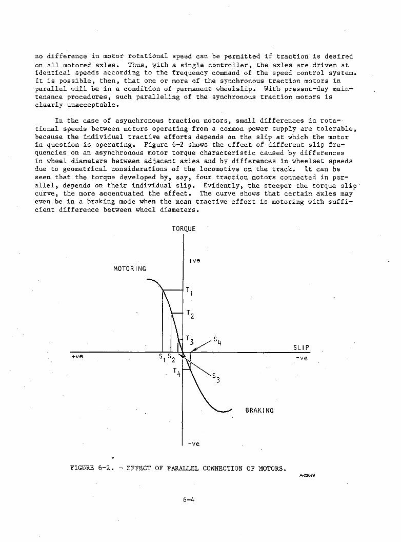
no difference in motor rotational speed can be permitted if traction is desired on all motored axles. Thus, with a single controller, the axles are driven at identical speeds according to the frequency command of the speed control system. It is possible, then, that one or more of the synchronous traction motors in parallel will be in a condition of permanent wheelslip. With present-day maintenance procedures, such paralleling of the synchronous traction motors is clearly unacceptable.
In the case of asynchronous traction motors, small differences in rotational speeds between motors operating from a common power supply are tolerable, because the individual tractive efforts depends on the slip at which the motor in question is operating. Figure 6-2 shows the effect of different slip frequencies on an asynchronous motor torque characteristic caused by differences in wheel diameters between adjacent axles and by differences in wheelset speeds due to geometrical considerations of the locomotive on the track. It can be seen that the torque developed by, say, four traction motors connected in parallel, depends on their individual slip. Evidently, the steeper the torque slip curve, the more accentuated the effect. The curve shows that certain axles may even be in a braking mode when the mean tractive effort is motoring with sufficient difference between wheel diameters.
TORQUE
FIGURE 6-2. - EFFECT OF PARALLEL CONNECTION OF MOTORS.A-22679
6-4
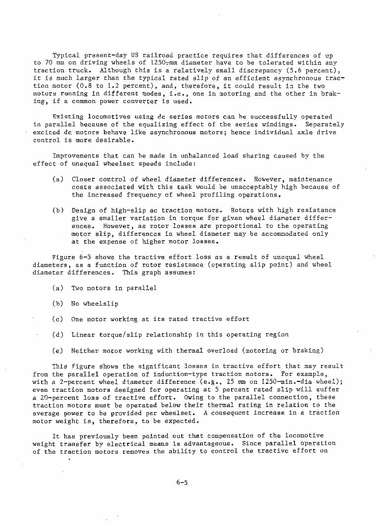
Typical present-day US railroad practice requires that differences of up to 70 mm on driving wheels of 1250-jnm diameter have to be tolerated within any traction truck. Although this is a relatively small discrepancy (5.6 percent), it is much larger than the typical rated slip of an efficient asynchronous traction motor (0.8 to 1.2 percent), and, therefore, it could result in the two motors running in different modes, i.e., one in motoring and the other in braking, if a common power converter is used.
Existing locomotives using dc series motors can be successfully operated in parallel because of the equalizing effect of the series windings. Separately excited dc motors behave like asynchronous motors; hence individual axle drive control is more desirable.
Improvements that can be made in unbalanced load sharing caused by the effect of unequal wheelset speeds include:
(a) Closer control of wheel diameter differences. However, maintenance costs associated with this task would be unacceptably high because of the increased frequency of wheel profiling operations.
(b) Design of high-slip ac traction motors. Rotors with high resistance give a smaller variation in torque for given wheel diameter differences. However, as rotor losses are proportional to the operating motor slip, differences in wheel diameter may be accommodated only at the expense of higher motor losses.
Figure 6-3 shows the tractive effort loss as a result of unequal wheel, diameters, as a function of rotor resistance (operating slip point) and wheel diameter differences. This graph assumes:
(a) Two motors in parallel
(b) No wheelslip
(c) One motor working at its rated tractive effort
(d) Linear torque/slip relationship in this operating region
(e) Neither motor working with thermal overload (motoring or braking)
This figure shows the significant losses in tractive effort that may result from the parallel operation of induction-type traction motors. For example, with a 2-percent wheel diameter difference (e.g., 25 mm on 1250-min.-dia wheel); even traction motors designed for operating at 5 percent rated slip will suffer a 20-percent loss of tractive effort. Owing to the parallel connection, these traction motors must be operated below their thermal rating in relation to the average power to be provided per wheelset. A consequent increase in a traction motor weight is, therefore, to be expected.
It has previously been pointed out that compensation of the locomotive weight transfer by electrical means is advantageous. Since parallel operation of the traction motors removes the ability to control the tractive effort on
6-5
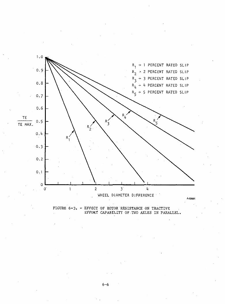
0
9
8
7
6
5
k
3
2
1
0
R1 1 PERCENT RATED SLIPR2 2 PERCENT RATED SLIP
R3 3 PERCENT RATED SLIIPR* -> k PERCENT RATED SLIIP
R5 5 PERCENT RATED SLIIP
2 3 k
WHEEL DIAMETER DIFFERENCEA -2 2 68 1
FIGURE 6-3. - EFFECT OF ROTOR RESISTANCE ON TRACTIVEEFFORT CAPABILITY OF TWO AXLES IN PARALLEL.
the individual axles, adhesion is adversely affected. The situation is exacerbated by distributing tractive effort per axle on the basis of arbitrary wheel diameter differences.
However, in the case of induction-type traction motors, the fixed shunt characteristic enables a slipping wheelset to be effectively coupled to the parallel-connected motors, and, therefore, the requirement for additional wheel slip protection is less severe.
The effects of motor characteristics on wheel slip are as follows:
(a) The correction of wheelslip may adversely affect the drawbar pull of the locomotive unless a favorable motor torque/speed curve exists, as is the case with ac asynchronous motors or separately excited dc motors. In these cases the wheelslip is largely self correcting on the offending axle(s) because of the exceedingly rapid torque falloff as speed rises with constant excitation. Tractive effort is only lost therefore on the spinning axle.
(b) The characteristics of series motors deny the self-correction of spin First the spin detection system must establish that a spin is occurring; then power must be removed through the motor controller from the affected axle drive. When individual axle controls are used, the other axles will not be affected. However, if the motor is also in series with other traction motors, power will also be removed from these (non-spinning) axles. Drawbar pull of the locomotive is therefore seriously affected. Even though a favorable torque/speed charac teristic of a traction motor may exist, there may be an additional requirement for load sharing control of adjacent axles.
(4) The Effect of Axle Load Fluctuations and Electromechanical Transients: Assuming a constant adhesion coefficient between wheel and rail, the maximum achievable tractive effort will vary with variations in axle load. Large transient variations in the axle load due to track roughness will tend to cause transient loss of adhesion (wheelslip) when operation is near the adhesion limit. Variations of tractive effort caused by mechanical torque variations in the drive assembly (motor torque pulsation, gear backlash, etc.), will have similar effects.
Optimum use of adhesion requires that at any instant the ratio of tractive effort to axle load to be slightly below the limiting value of the adhesion coefficient.
Section 6(c) describes the relation between axle load (static), unsprung mass, and dynamic axle load. The force contribution from unsprung mass is oscillatory and must, therefore, be minimized if transient wheelslip is to be avoided. The tractive effort resulting from such a transient wheelslip condition would be difficult to predict, for no realistic data are available on this nonlinear effect.
6 - 7
It is not desirable, even if it were possible, to vary the tractive effort to follow the dynamic axle load, as jerk levels would be compromised and difficulties with transmission stiffnesses would lead to incipient instability problems.
b. Summary of the Abilities of AC and DC Traction Motors.
(1) Summary. The ability of ac and dc locomotives to achieve maximum traction at the wheel-rail interface is summarized as follows:
(a) Optimum adhesion is obtained for a given locomotive by:
— Compensating for weight transfer
— Providing smooth control of tractive effort
— Providing a fast acting wheelslip/wheelslide protection on the slipping axle(s) only
(b) Electrical weight transfer compensation requires individual axle, closed-loop control of tractive effort. In addition, traction motors are required to handle additional loads over the mechanically compensated locomotives.
(c) Favorable motor torque/speed characteristics for inherent wheelslip protection may be utilized in parallel motor configurations. Locomotives with individual axle control may benefit from a fast loadshedding slip characteristic as long as the time constants of the load sharing circuits have been made deliberately long in order that they will not have time to affect the torque of a slipping motor before it corrects itself.
(d) Additional wheelslip protection may be required on motors with imminent "load shedding" slip characteristics.
(e) Individual axle control may be required for ac asynchronous motors because of the stringent requirement for equal load sharing. Synchronous machines will require individual axle control.
(f) Smooth control of tractive effort is possible in both dc and ac motor drives. However, some ac motor drives may suffer from torque pulsations at low frequency.
(g) Electrical weight transfer compensation may be used advantageously for individually fed and controlled axle drives.
(h) No significant advantages are seen in adhesion utilization of ac traction motors over separately excited dc motors with smooth notchless control of tractive effort.
6-8
(2) Conclusion. It has been shown that parallel operation of asynchronous traction motors leads to a combination of reduction in starting tractive effort, heavier traction motors, poor adhesion utilization, and greater wheel- set maintenance. This is the price that must be paid for a reduction in controller complexity.
For applications where the tractive effort at starting and the utilization of adhesion are essential performance requirements, as in the case of freight locomotives, the parallel connection of ac traction motors is highly undesirable.
Where a large number of ac traction motors are involved, some degree of paralleling may be cost effective, especially if adhesion and motor sizes are not of prime concern.
In view of the high axle power, the economic side of individual axle control is not severe, especially for the power conditioning, because it may reduce the need for paralleling power semiconductors.
c. Unsprung Mass and Its Effect on Track and Locomotive Maintenance. Vertical and lateral accelerations on truck and axle components caused by uneven track and wheel profiles give rise to large dynamic forces imparted to the permanentway structure and the rolling stock. Because both the capital investment in the track and maintenance of the system are functions of the track stresses, these dynamic forces must be minimized.
British Rail has developed an equation that determines the peak vertical wheel loads during such dynamic conditions according to:
Q = peak axle load, tonnes
Q0 = static axle load, tonnes
X = angle of track perturbation, radians = 0.0154 ■
k = track stiffness, tonnes/mm = 9.06 tonnes/mm
v = vehicle velocity, kpm
w = unsprung wheel load, tonnes
g = gravitational constant, m/sec^ = 9.81
It can be seen that the static wheel load, Q0 , forms only a part of thetotal dynamic wheel load. Although it is customary in railroad practice torefer only to the maximum static axle load when sizing the track material,
(6-1)where
6-9

the above algorithm shows that other factors must also be taken into account. This algorithm, which relates various aspects of truck and track design, is used to examine the concept of equivalent track damage. In this connection, the peak wheel loads of the existing rolling stock will be equated to the peak wheel loads of a hypothetical locomotive traction drive design with reduced unsprung mass.
Weights for a typical dc motor freight locomotive with axle-hung motorare:
Static axle load, tonnes = 30Unspring mass per axle, tonnes = 3.8 Speed, kph = 80
The peak wheel load is calculated using equation (6-1) with the following typical track constants:
X = 0.0154 radians (0.882 deg)
Q = 30 + 0.0154 x 80 x 12.23 x^ 2 06 x 3.8 = 58.23 tonnes/axle 9.81
Similarly for a static load of 25 tonnes and unsprung mass of 2 tonnes, Q = 45.8 tonnes/axle.
The foregoing shows that at 80 kph an existing locomotive with a static axle load of 30 tonnes/axle and an unsprung mass of 3.8 tonnes/axle imparts 28 percent more vertical.peak wheel load than a 25 tonnes/axle locomotive with an unsprung mass of 2.0 tonnes. Because of the state of track caused by the large existing shock loads aggravated by deferred maintenance, a reduced static axle load of 25 tonnes has been selected for the ac locomotive trial specification.
For high-speed locomotives used in passenger service it is imperative to reduce the unsprung mass as much as possible in order to limit the peak axle loads, for the unsprung mass will also cause large side loads that will impact the track. The consequent effect of high unsprung mass on track damage due to high shock loads is a fundamental concern in locomotive design. A reduction in unsprung mass directly reduces the incidence of mechanical failure of the track and truck parts, including the motor, if axle-hung.^
The increased potential power density of an ac motor over its dc counterpart can be advantageously used to reduce unsprung mass. It has already been established that the requirement for more powerful traction motors is limited. The German locomotive E120, for example, demonstrates a reduction in truck weight from 22 to 15 tons achieved by replacing the dc motors with ac asynchronous motors of a higher rating. Locomotives with ac motors would be inherently better suited to higher speed operation, where unsprung mass is of prime importance.
6-10

REFERENCES
Jenkins, H.H., et al., "The Effect of Track and Vehicle Parameters on Wheel/ Rail Vertical Dynamic Forces," Railway Engineering Journal, January 1974.
6 - 1 1
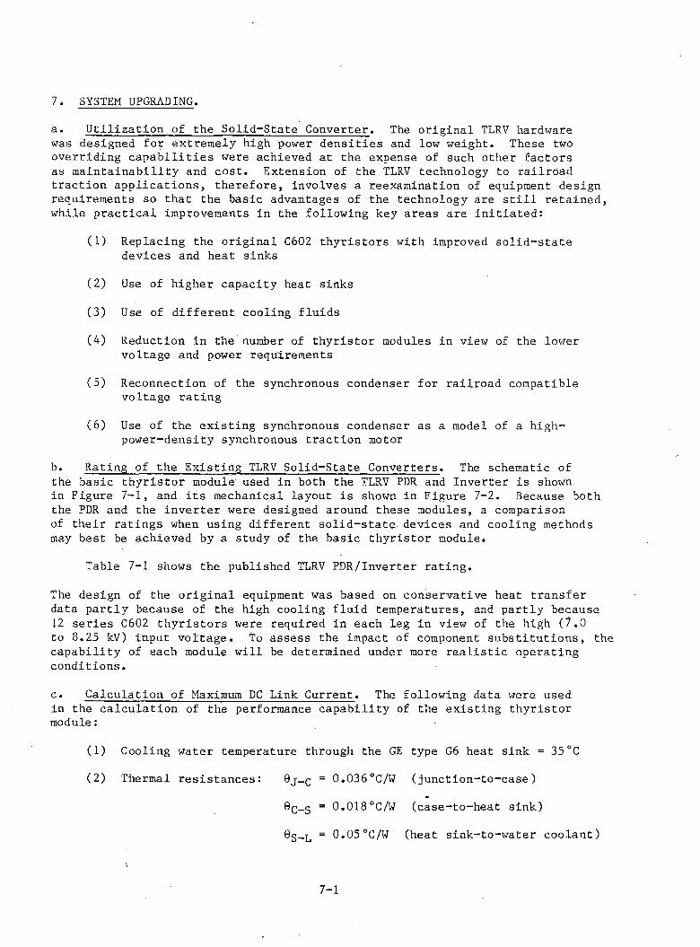
7. SYSTEM UPGRADINGa. Utilization of the Solid-State Converter. The original TLRV hardware was designed for extremely high power densities and low weight. These two overriding capabilities were achieved at the expense of such other factors as maintainability and cost. Extension of the TLRV technology to railroad traction applications, therefore, involves a reexamination of equipment design requirements so that the basic advantages of the technology are still retained, while practical improvements in the following key areas are initiated:
(1) Replacing the original C602 thyristors with improved solid-state devices and heat sinks
(2) Use of higher capacity heat sinks
(3) Use of different cooling fluids
(4) Reduction in the number of thyristor modules in view of the lower voltage and power requirements
(5) Reconnection of the synchronous condenser for railroad compatible voltage rating
(6) Use of the existing synchronous condenser as a model of a high- power-density synchronous traction motor
b. Rating of the Existing TLRV Solid-State Converters. The schematic of the basic thyristor module' used in both the TLRV PDR and Inverter is shownin Figure 7-1, and its mechanical layout is shown in Figure 7-2. Because both the PDR and the inverter were designed around these modules, a comparison of their ratings when using different solid-state devices and cooling methods may best be achieved by a study of the basic thyristor module.
Table 7-1 shows the published TLRV PDR/Inverter rating.
The design of the original equipment was based on conservative heat transfer data partly because of the high cooling fluid temperatures, and partly because 12 series C602 thyristors were required in each leg in view of the high (7.0 to 3.25 kV) input voltage. To assess the impact of component substitutions, the capability of each module will be determined under more realistic operating conditions.
c. Calculation of Maximum DC Link Current. The following data were used in the calculation of the performance capability of the existing thyristor module:
(1) Cooling water temperature through the GE type G6 heat sink = 35°C
(2) Thermal resistances: ®j-c = 0.036°C'/W (junction-to-case)
0C_s = 0.018°C/W (case-^-to-heat sink)
®S-L = 0.05°C/W (heat sink-to-water coolant)
7-1
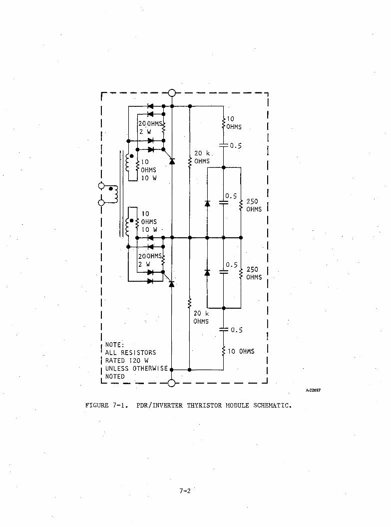
A -2 2 6 9 7
FIGURE 7-1. PDR/INVERTER THYRISTOR MODULE SCHEMATIC.
7 - 2
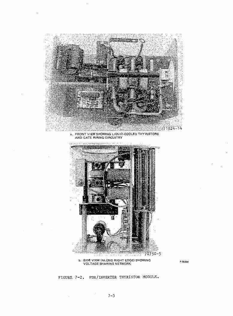
71025-15a. F R O N T V I EW S H O W I N G LIQUID-COOLED T H Y R I S T O R S
A N D G A T E FI RING CIRCUITRY
'70750-5b. SIDE V I E W ( A L O N G R IGHT EDGE) S H O W I N G
V O L T A G E S H A R I N G N E T W O R K F -3 5 4 9 9
FIGURE 7-2. PDR/INVERTER THYRISTOR MODULE.
7 - 3
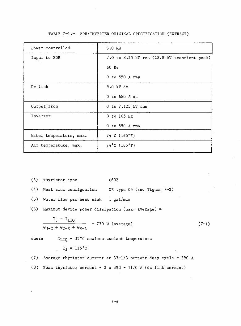
TABLE 7-1.- PDR/INVERTER ORIGINAL SPECIFICATION (EXTRACT)
Power controlled 6.0 MWInput to PDR 7.0 to 8.25 kV rms (28.8 kV transient peak)
60 Hz
0 to 550 A rms
Dc link 9.0 kV dc
0 to 680 A dc
Output from 0 to 7.125 kV rmsInverter 0 to 165 Hz
0 to 550 A rms
Water temperature, max. 74°C (165°F)
Air temperature, max. 74°C (165°F)
(3) Thyristor type C602
(4) Heat sink configuation GE type G6 (see Figure 7-2)
(5) Water flow per heat sink 1 gal/min
(6) Maximum device power dissipation (max. average) =
TJ “ tLIQ------------------ = 770 W (average) (7-1)eJ-C + eC-S + eS-L
where Tljq = 35°C maximum coolant temperature
Tj = 115°C
(7) Average thyristor current at 33-1/3 percent duty cycle = 390 A
(8) Peak thyristor current = 3 x 390 = 1170 A (dc link current)
7-4
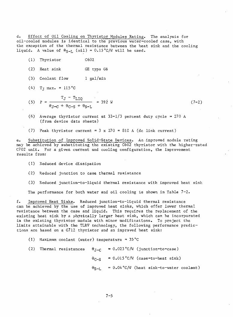
d. Effect of Oil Cooling on Thyristor Modules Rating. The analysis foroil-cooled modules is identical to the previous water-cooled case, withthe exception of the thermal resistance between the heat sink and the cooling liquid. A value of Sg-L (oil) = 0.15°C/W will be used.
(1) Thyristor C602(2) Heat sink GE type G6(3) Coolant flow 1 gal/min(4) Tj max. = 115°C
TJ “ tLIQ(5) P = -------------- = 392 W (7-2)9J-C + eC-S + eS-L
(6) Average thyristor current at 33-1/3 percent duty cycle = 270 A (from device data sheets)
(7) Peak thyristor current = 3 x 270 = 810 A (dc link current)e. Substitution of Improved Solid-State Devices. An improved module rating may be achieved by substituting the existing C602 thyristor with the higher-rated C702 unit. For a given current and cooling configuration, the improvement results from:
(1) Reduced device dissipation(2) Reduced junction to case thermal resistance(3) Reduced junction-to-liquid thermal resistance with improved heat sink The performance for both water and oil cooling is shown in Table 7-2.
f. Improved Heat Sinks. Reduced junction-to-liquid thermal resistance can be achieved by the use of improved heat sinks, which offer lower thermal resistance between the case and liquid. This requires the replacement of the existing heat sink by a physically larger heat sink, which can be incorporated in the existing thyristor module with minor modifications. To project the limits attainable with the TLRV technology, the following performance predictions are based on a C712 thyristor and an improved heat sink:
(1) Maximum coolant (water) temperature = 35°C(2) Thermal resistances 9j-c = 0.023°C/W (junction-to-case)
9q_2 = 0.015°C/W (case-to-heat sink)0g_L = 0 .0 4 ° C / W (heat s in k - to -w a te r coola< it)
7 - 5
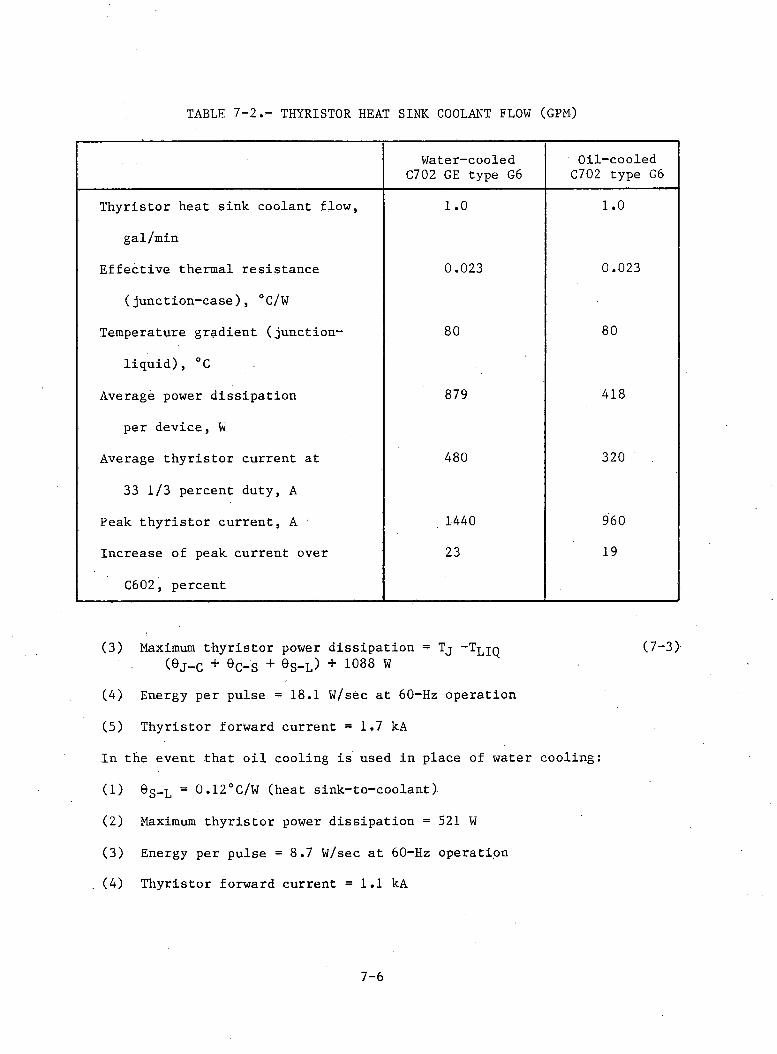
TABLE 7-2.- THYRISTOR HEAT SINK COOLANT FLOW (GPM)
Water-cooled C702 GE type G6
Oil-cooled C702 type G6
Thyristor heat sink coolant flow, 1.0 1.0
gal/min
Effective thermal resistance 0.023 0.023
(junction-case), °C/W
Temperature gradient (junction- 80 80
liq u id ), °C
Average power dissipation 879 418
per device, W
Average th yristor current at 480 320
33 1/3 percent duty, A
Peak th yristor current, A ■ 1440 960
Increase of peak current over 23 19
C602, percent
(3) Maximum thyristor power dissipation = Tj "T^jq (7-3)(eJ-C + 6C-S + &s- l ) + 1088 w
(4) Energy per pulse = 18.1 W/sec at 60-Hz operation
(5) Thyristor forward current = 1.7 kA
In the event that o il cooling is used in place of water cooling:
(1) 6g-L = 0.12°C/W (heat sink-to-coolant)
(2) Maximum th yristor power dissipation = 521 W
(3) Energy per pulse = 8 .7 W/sec a t 60-Hz operation
(4) Thyristor forward current = 1.1 kA
7-6
g. Uprating of Synchronous Condenser. In the TLRV application, the purpose of the synchronous condenser was to provide reactive power to line-commutate the inverter and to provide power factor correction for the linear induction motor. This section reevaluates the following applications for the existing hardware:
(1) Synchronous condenser for a high-voltage, high-power-factor (Cos 0 = 0 .9 5 ), three-phase traction motors in place of the original LIM to assist inverter line-commutation
(2) Adapt the synchronous condenser as a model of a synchronous traction machine, with an option to reconnect to low voltage application
h. U tilization of Synchronous Condenser in Conjunction with Three-Phase Traction Motor. This system assumes a single inverter and synchronous condenser
supplying a ll axles in parallel and is therefore an unlikely candidate. The power factor of an induction-type traction motor is typically 95 percent, compared with the 70-percent rated power factor of a linear induction motor. This improved power factor enables the synchronous condenser in i ts existing form to line-commutate a larger load, subject only to the lim itations of the inverter and synchronous condenser cooling.
For this application, the rating of the synchronous condenser, which is the only source of reactive power onboard the six-axle locomotive, is established by the combined reactive requirements of the six traction motors and the single line-commutated inverter.
(1) Reactive Loads. The two types of reactive loads can be estimated as follows:
(a) The Traction Motor Reactive Load. Requirements are based on the rated power input to the six traction motors at a 95-percent power factor.The power input to the traction motors is estimated as
PTM = PIN ~ WI - WSC (7-4)
where
PTM = inPut power to the traction motors
Pjjj = input power to the inverter
Wj = inverter losses
Wgc = synchronous condenser losses
Table 7-3 shows the reactive power requirements of the traction motors.
7 - 7

TABLE 7-3.- TRACTION MOTOR REAL AND REACTIVE POWER REQUIREMENTS.
Parameter Water-cooled Oil-cooled
Pin . mw 10.4 7.13
W RW 100 33
ws c , kw 300 100
P M, MW 10.0 7.0
Reactive power 3290 2190requirement(motor), kVAR
(b) Inverter Leading Reactive Power Requirement. Operation of a lin e- commutated inverter requires leading reactive kva, which in this case is supplied by the synchronous condenser. Two factors contribute tothe reactive requirements of the line-commutated inverter: (1) the storedenergy associated with the commutating reactance and (2) the phase-delay angle control of the thyristors, which causes an effective phase shift between inverter voltage and current. The former affects the so-called overlap angle (p ); the la tte r affects the firing delay angle (®«) of the inverter.
The commutating reactance is presented by the p arallel connection of the leakage reactance of the traction motor and the negative sequence reactance of the synchronous condenser.
The inverter requirements are shown in Table 7-4.
(c) Synchronous Condenser Requirements. The synchronous condenser requirments are determined from the sum of the reactive requirements of the traction motors and the inverter, as shown in Table 7-5.
The reactive power requirments with three-phase traction motors are within the ratings of the water-cooled inverter and synchronous condenser. However, the full power rating of an oil-cooled inverter cannot be utilized because of the limitations imposed by the existing synchronous condenser if i t were o il cooled. Table 7-6 summarizes the maximum traction motor ratings that can be obtained with a line-commutated inverter/synchronous condenser, type variable-voltage, variable-frequency power supply.
7-8
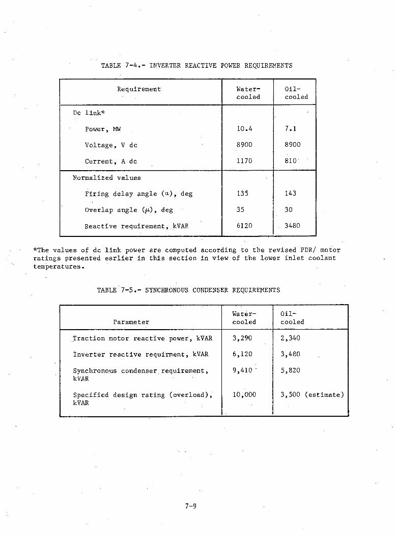
TABLE 7-4.- INVERTER REACTIVE POWER REQUIREMENTS
Requirement Water-cooled
Oil-cooled
Dc link*
Power, MW 10.4 7.1
Voltage, V dc 8900 8900
Current, A dc 1170 810
Normalized values
Firing delay angle (a), deg 135 143
Overlap angle (/t), deg 35 30
Reactive requirement, kVAR 6120 3480
*The values of dc link power are computed according to the revised PER/ motor ratings presented earlier in this section in view of the lower inlet coolant temperatures.
TABLE 7 - 5 .- SYNCHRONOUS CONDENSER REQUIREMENTS
Water- Oil-Parameter cooled cooled
Traction motor reactive power, kVAR 3,290 2,340
Inverter reactive requirment, kVAR 6,120 3,480
Synchronous condenser requirement, kVAR
9,410 5,820
Specified design rating (overload), kVAR
10,000 3,500 (estim ate)
7-9
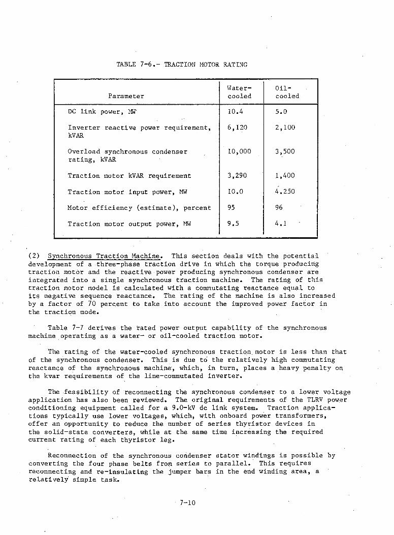
TABLE 7-6.- TRACTION MOTOR RATING
ParameterWater-cooled
Oil-coOled
DC link power, MW 10.4 5.0
Inverter reactive power requirement, kVAR
6,120 2,100
Overload synchronous condenser rating, kVAR
10,000 3,500
Traction motor kVAR requirement 3,290 1,400
Traction motor input power, MW 10.0 4.250
Motor efficiency (estim ate), percent 95 96
Traction motor output power, MW 9.5 4.1
(2) Synchronous Traction Machine. This section deals with the potential development of a three-phase traction drive in which the torque producing traction motor and the reactive power producing synchronous condenser are integrated into a single synchronous traction machine. The rating of this traction motor model is calculated with a commutating reactance equal to its negative sequence reactance. The rating of the machine is also increased by a factor of 70 percent to take into account the improved power factor in the traction mode.
Table 7-7 derives the rated power output capability of the synchronous machine operating as a water- or oil-cooled traction motor.
The rating of the water-cooled synchronous traction motor is less than that of the synchronous condenser. This is due to the relativ ely high commutating reactance of the synchronous machine, which, in turn, places a heavy penalty on the kvar requirements of the line-commutated inverter.
The fe a sib ility of reconnecting the synchronous condenser to a lower voltage application has also been reviewed. The original requirements of the TLRV power conditioning equipment called for a 9.0-kV dc link system. Traction applications typically use lower voltages, which, with onboard power transformers, offer an opportunity to reduce the number of series thyristor devices in the so lid -state converters, while at the same time increasing the required current rating of each thyristor leg.
Reconnection of the synchronous condenser stator windings is possible by converting the four phase belts from series to parallel. This requires reconnecting and re-insulating the jumper bars in the end winding area, a relatively' simple task.
7-10
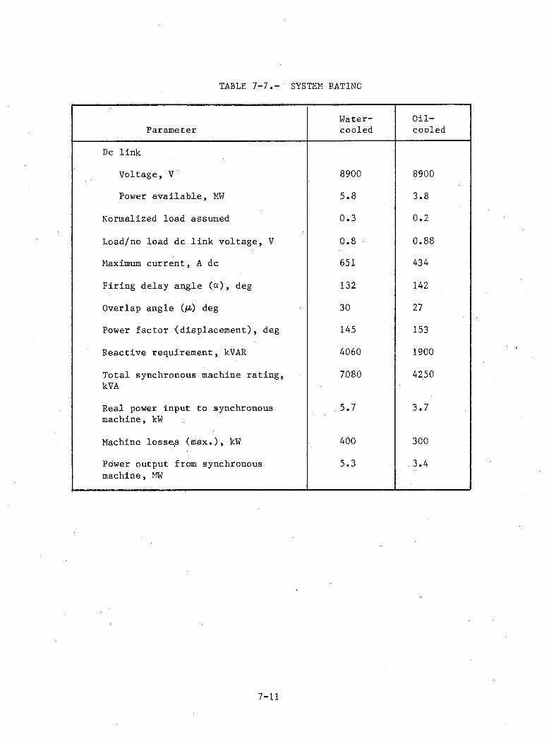
TABLE 7-7.- SYSTEM BATING
ParameterWater-cooled
Oil-cooled
Dc link
Voltage, V 8900 8900
Power available, MW 5.8 CO•
CO
Normalized load assumed 0.3 0 . 2
Load/no load dc link voltage, V 0.8 0.88
Maximum current, A dc 651 434
Firing delay angle (ct), deg 132 142
Overlap angle (/£) deg 30 27
Power factor (displacement), deg 145 153
Reactive requirement, kVAR 4060 1900
Total synchronous machine rating, kVA
7080 4250
Real power input to synchronous machine, kW
.5 .7 3.7
Machine losse^s (m ax.), kW 400 300
Power output from synchronous machine, MW
5.3 3.4
7-11
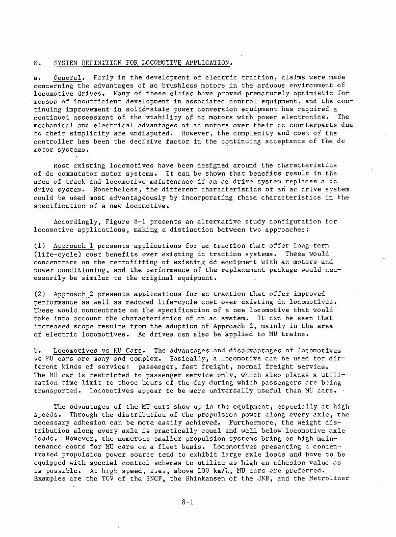
8 SYSTEM DEFINITION FOR LOCOMOTIVE APPLICATION.a. General. Early in the development of e le c tr ic tractio n , claims were made concerning the advantages of ac brushless motors in the arduous environment of locomotive drives. Many of these claims have proved prematurely optim istic for reason of insufficient development in associated control equipment, and the continuing improvement in so lid -state power conversion equipment has required a continued assessment of the v iab ility of ac motors with power electron ics. The mechanical and e le c tr ic a l advantages of ac motors over their dc counterparts due to their sim plicity are undisputed. However, the complexity and cost of the controller has been the decisive factor in the continuing acceptance of the dc motor systems.
Most existing locomotives have been designed around the characteristics of dc commutator motor systems. It can be shown that benefits result in the area of track and locomotive maintenance if an ac drive system replaces a dc drive system. Nonetheless, the different characteristics of an ac drive system could be used most advantageously by incorporating these characteristics in the specification of a new locomotive.
Accordingly, Figure 8-1 presents an alternative study configuration for locomotive applications, making a distinction between two approaches:
(1) Approach 1 presents applications for ac traction that offer long-term (life -cy c le ) cost benefits over existing dc traction systems. These would concentrate on the re tro fittin g of existing dc equipment with ac motors and power conditioning, and the performance of the replacement package would necessarily be similar to the original equipment.
(2) Approach 2 presents applications for ac traction that offer improved performance as well as reduced life -cy cle cost over existing dc locomotives. These would concentrate on the specification of a new locomotive that would take into account the ch aracteristics of an ac system. I t can be seen that increased scope results from the adoption of Approach 2, mainly in the area of e le c tric locomotives. Ac drives can also be applied to MU train s.
b. Locomotives vs MU Cars. The advantages and disadvantages of locomotivesvs MU cars are many and complex. Basically, a locomotive can be used for d ifferent kinds of service: passenger, fast freigh t, normal freight service.The MU car is restric ted to passenger service only, which also places a u t i l i zation time lim it to those hours of the day during which passengers are being transported. Locomotives appear to be more universally useful than MU cars.
The advantages of the MU cars show up in the equipment, especially at high speeds. Through the distribution of the propulsion power along every axle , the necessary adhesion can be more easily achieved. Furthermore, the weight distribution along every axle is p ractically equal and well below locomotive axle loads. However, the numerous smaller propulsion systems bring on high maintenance costs for MU cars on a fleet basis. Locomotives presenting a concentrated propulsion power source tend to exhibit large axle loads and have to be equipped with special control schemes to u tilize as high an adhesion value as is possible. At high speed, i . e . , above 200 km/h, MU cars are preferred. Examples are the TGV of the SNCF, the Shinkansen of the JNR, and the Metroliner
8 - 1
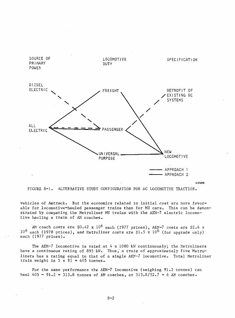
SOURCE OFPRIMARYPOWER
LOCOMOTIVEDUTY
SPECIFICATION
DIESEL
A -22696
FIGURE 8-1 . ALTERNATIVE STUDY CONFIGURATION FOR AC LOCOMOTIVE TRACTION.
vehicles of Amtrack. But the economics related to in itia l cost are more favorable for locomotive-hauled passenger trains than for MU cars . This can he demonstrated by comparing the Metroliner MU trains with the AEM-7 e le c tr ic locomotive hauling a train of AM coaches.
AM coach costs are $0.42 x 10 each (1977 p rice s), AEM-7 costs are $2.6 x 10⁶ each (1978 p rice s ), and Metroliner costs are $1.5 x 10 (for upgrade only) each (1977 p rice s).
The AEM-7 locomotive is rated at 4 x 1080 kW continuously; the Metroliners have a continuous rating of 895 kW. Thus, a train of approximately five Metroliners has a rating equal to that of a single AEM-7 locomotive. Total Metroliner train weight is 5 x 81 = 405 tonnes.
For the same performance the AEM-7 locomotive (weighing 91.2 tonnes) can haul 405 - 91.2 = 313.8 tonnes of AM coaches, or 313 .8 /52 .7 = 6 AM coaches.
8 - 2
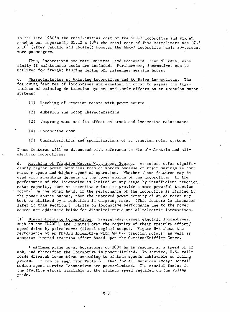
In the late 1980's the to ta l in itia l cost of the AEM-7 locomotive and six AM coaches was reportedly $5.12 x 10^; the to ta l cost of five Metroliners was $7.5 x 10 (after rebuild and update); however the AEM-7 locomotive hauls 20-percent more passengers.
Thus, locomotives are more universal and economical than MU cars, espec ia lly if maintenance costs are included. Furthermore, locomotives cah be utilized for freight hauling during off passenger service hours.
c . C haracteristics of Existing Locomotives and AC Drive Locomotives. The following features of locomotives are examined in order to assess the lim itations of existing dc traction systems and their effects on ac traction motor systems:
(1) Matching of traction motors with power source
(2) Adhesion and motor ch aracteristics
(3) Unsprung mass and its effect on track and locomotive maintenance
(4) Locomotive cost
(5) C haracteristics and specifications of ac traction motor systems
These features w ill be discussed with reference to d iese l-e lectric and a l l e le c tric locomotives.
d. Matching of Traction Motors With Power Source. Ac motors offer s ig n ificantly higher power densities than dc motors because of their savings in commutator space and higher speed of operation. Whether these features may be used with advantage depends on the power source of the locomotive. If the performance of the locomotive is limited at any stage by insufficient tractio n - motor capacity, then an incentive exists to provide a more powerful traction motor. On the other hand, if the performance of the locomotive is limited by the power source output, then the improved power density of an ac motor may best be utilized by a reduction in unsprung mass. (This feature is discussed la ter in this sectio n .) Limits on locomotive performance due to the power source are addressed below for d ie se l-e lectric and a l l -e le c tr ic locomotives.
(1) D iesel-Electric Locomotives: Present-day diesel e le c tric locomotives,such as the FD40PH, are limited over the majority of their tractiv e e f fo r t/ speed drive by prime mover (diesel engine) output. Figure 8-2 shows the performance of an FD40PH locomotive with GM D77 traction motors, as well as adhesion limited traction effort based upon the Curtius/Kniffler Curve.
A maximum prime mover horsepower of 3000 hp is reached at a speed of 12 mph, and thereafter the locomotive is power-limited. In service, U.S. r a i l roads dispatch locomotives according to minimum speeds achievable on ruling grades. I t can be seen from Table 8-1 that for a ll services except Conrail medium speed service locomotives are power-limited. The crucial factor is the tractive effo rt available at the minimum speed required on the ruling grade.
8-3
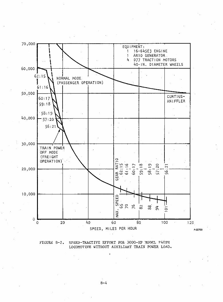
FIGURE 3-2. SPEED-TRACTIVE EFFORT FOR 3000-HP MODEL F40PHLOCOMOTIVE WITHOUT AUXILIARY TRAIN POWER LOAD.
8-4
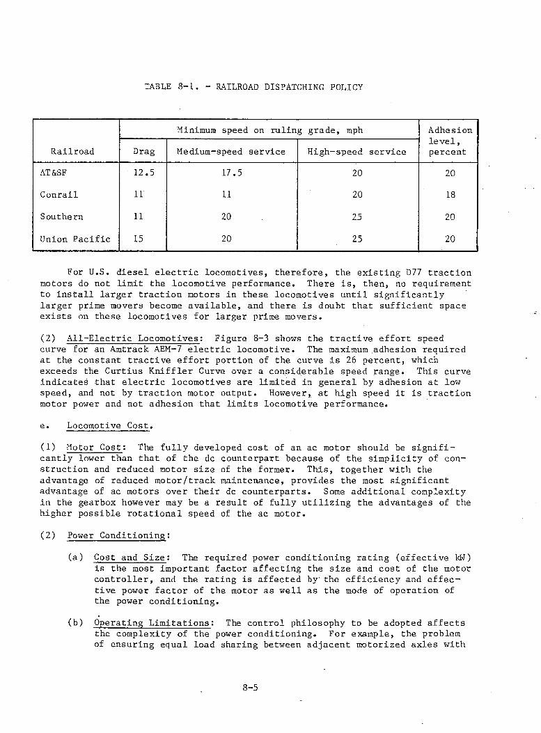
TABLE 8-1. - RAILROAD DISPATCHING POLICY
Railroad
Minimum speed on ruling grade, mph Adhesion lev el, percentDrag Medium-speed service High-speed service
AT&SF 12.5 17.5 20 20
Conrail 11 11 20 18
Southern 11 20 25 20
Union Pacific 15 20 25 20
For U.S. diesel e le c tr ic locomotives, therefore, the existing D77 traction motors do not limit the locomotive performance. There is , then, no requirement to in sta ll larger traction motors in these locomotives until significantly larger prime movers become available, and there is doubt that sufficient space exists on these locomotives for larger prime movers.
(2) A ll-E lectric Locomotives: Figure 8-3 shows the tractiv e effort speedcurve for an Amtrack AEM-7 e le c tric locomotive. The maximum adhesion required at the constant tractiv e effo rt portion of the curve is 26 percent, which exceeds the Gurtius Kniffler Curve over a considerable speed range. This curve indicates that e le c tr ic locomotives are limited in general by adhesion at low speed, and not by traction motor output. However, at high speed i t is traction motor power and not adhesion that limits locomotive performance.
e. Locomotive Cost.
(1) Motor Cost: The fu lly developed cost of an ac motor should be s ig n ificantly lower than that of the dc counterpart because of the sim plicity of construction and reduced motor size of the former. This, together with the advantage of reduced motor/traclc maintenance, provides the most significant advantage of ac motors over their dc counterparts. Some additional complexity in the gearbox however may be a result of fully u tilizing the advantages of the higher possible rotational speed of the ac motor.
(2) Power Conditioning:
(a) Cost and Size: The required power conditioning rating (effective kN)is the most important factor affecting the size and cost of the motor con troller, and the rating is affected by' the efficiency and effective power factor of the motor as well as the mode of operation of the power conditioning.
(b) Operating Lim itations: The control philosophy to be adopted affectsthe complexity of the power conditioning. For example, the problem of ensuring equal load sharing between adjacent motorized axles with
8-5
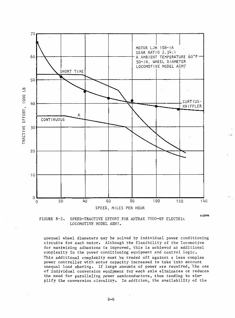
TRAC
TIVE
EFF
ORT,
10
00 L
B
0 ■ !---- .I---------J--------- »— ------------------ L— — — — I0 2 0 kO 6 0 8 0 1 0 0 1 2 0 1 4 0
SPEED, MILES PER HOURA-22698FIGURE 8-3. SPEED-TRACTIVE EFFORT FOR AMTRAK 7000-HP ELECTRIC
LOCOMOTIVE MODEL AEM7.
unequal wheel diameters may be solved by individual power conditioning c ircu its for each motor. Although the f le x ib ility of the locomotive for maximizing adhesions is improved, this is achieved at additional complexity in the power conditioning equipment and control lo g ic .This additional complexity must be traded off against a less complex power controller with motor capacity increased to take into account unequal load sharing. If large amounts of power are required, the use of individual conversion equipment for each axle eliminates or reduces the need for paralleling power semiconductors, thus tending to simplify the conversion circu itry . In addition, the av ailab ility of the
8 - 6
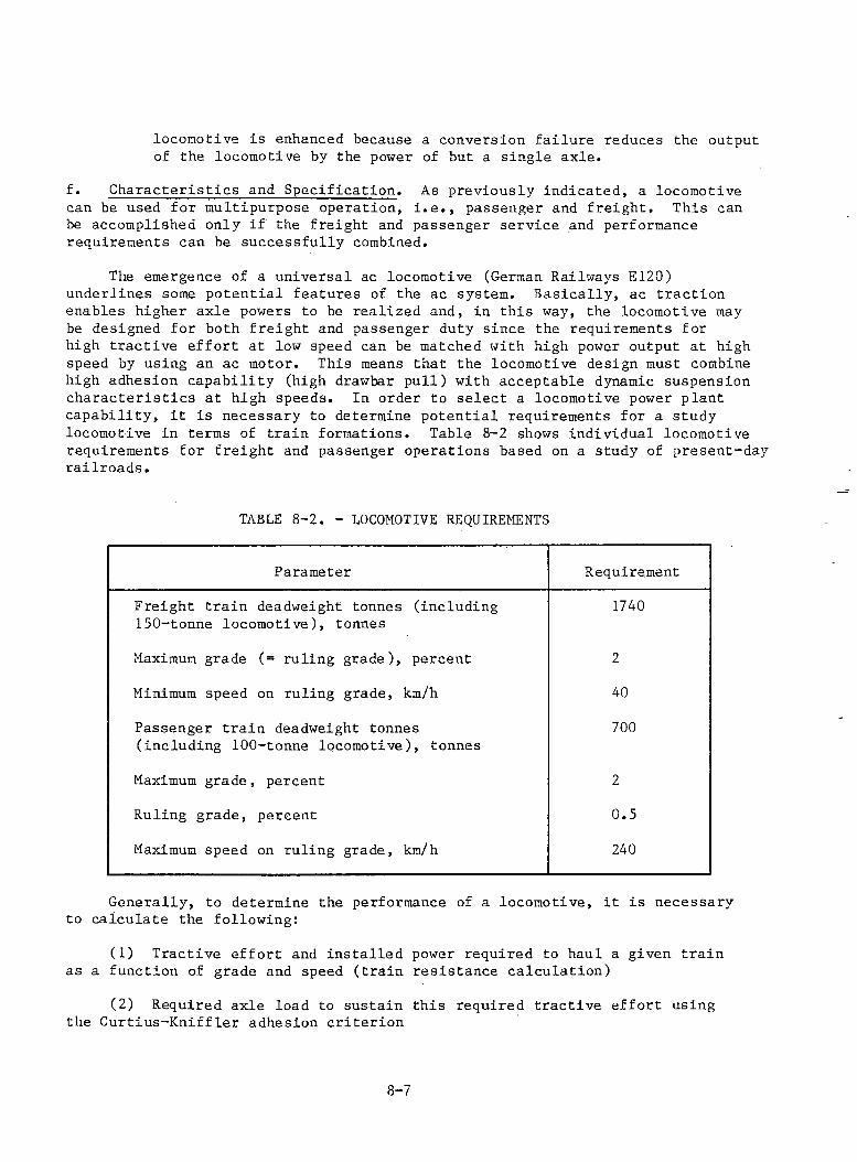
locomotive is enhanced because a conversion failure reduces the output of the locomotive by the power of but a single axle.
f. Characteristics and Specification. As previously indicated, a locomotive can be used for multipurpose operation, i.e., passenger and freight. This can be accomplished only if the freight and passenger service and performance requirements can be successfully combined.
The emergence of a universal ac locomotive (German Railways E120) underlines some potential features of the ac system. Basically, ac traction enables higher axle powers to be realized and, in this way, the locomotive may be designed for both freight and passenger duty since the requirements for high tractive effort at low speed can be matched with high power output at high speed by using an ac motor. This means that the locomotive design must combine high adhesion capability (high drawbar pull) with acceptable dynamic suspension characteristics at high speeds. In order to select a locomotive power plant capability, it is necessary to determine potential requirements for a study locomotive in terms of train formations. Table 8-2 shows individual locomotive requirements for freight and passenger operations based on a study of present-day railroads.
TABLE 8-2. - LOCOMOTIVE REQUIREMENTS
Parameter Requirement
Freight train deadweight tonnes (including 150-tonne locomotive), tonnes
1740
Maximum grade (= ruling grade), percent 2
Minimum speed on ruling grade, km/h 40
Passenger train deadweight tonnes (including 100-tonne locomotive), tonnes
700
Maximum grade, percent 2
Ruling grade, percent 0.5
Maximum speed on ruling grade, km/h 240
Generally, to determine the performance of a locomotive, it is necessary to calculate the following:
(1) Tractive effort and installed power required to haul a given train as a function of grade and speed (train resistance calculation) 2
(2) Required axle load to sustain this required tractive effort using the Curtius-Kniffler adhesion criterion
8-7
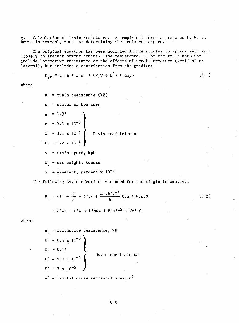
g. Calculation of Train Resistance. An empirical formula proposed by W. J. Davis is commonly used for determining the train resistance.
The original equation has been modified in FRA studies to approximate more closely to freight boxcar trains. The resistance, R, of the train does not include locomotive resistance or the effects of track curvature (vertical or lateral), but includes a contribution from the gradient
RFE = n (A + B WQ + CWQv + D2) + nWQG (8-1)
where
R = train resistance (kN)
n = number of box cars
A
B
C
D
v = train speed, kph
WQ = car weight, tonnes
G = gradient, percent x 10-2
The following Davis equation was used for the single locomotive:
= 0.36
= 3.0 x 10-3
= 3.1 x 10-5
= 1.2 x 10“4Davis coefficients
where
C*R1 = (b > + — + D'.v + E'.A’.V2 W.n + W.n.GW Wn
= B'Wn + C'n + D'vWn + E'A'v2 + Wn' G
Rl = locomotive resistance, kN -36.4 x 10
0.13
B'C'
D' = 9.3 x 10
E'
A'
-5 Davis coefficients
3 x 10“5
frontal cross sectional area, m2
(8-2)
8-8
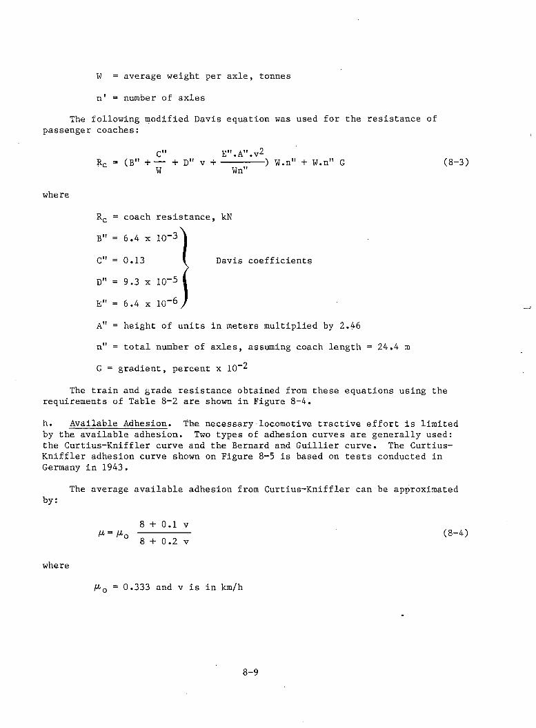
W = average weight per axle, tonnes
n' = number of axles
The following modified Davis equation was used for the resistance of passenger coaches:
C" E".A".v 2Rc = (B" + ----1- D" v + -- --- ---) W.n" + W.n" GW Wn" (8-3)
where
Davis coefficients
Rc = coach resistance, kN
B" = 6.4 x 10“3
C" = 0.13
D" = 9.3 x 10⁻⁵
E" = 6.4 x 10⁻⁶
A" = height of units in meters multiplied by 2.46
n" = total number of axles, assuming coach length = 24.4 m
G = gradient, percent x 10-3
The train and grade resistance obtained from these equations using the requirements of Table 8-2 are shown in Figure 8-4.
h. Available Adhesion. The necessary locomotive tractive effort is limited by the available adhesion. Two types of adhesion curves are generally used: the Curtius-Kniffler curve and the Bernard and Guillier curve. The Curtius- Kniffler adhesion curve shown on Figure 8-5 is based on tests conducted in Germany in 1943.
The average available adhesion from Curtius-Kniffler can be approximatedby:
M- o8 + 0.1 v 8 + 0.2 v (8-4)
where
/rQ = 0.333 and v is in km/h
8-9
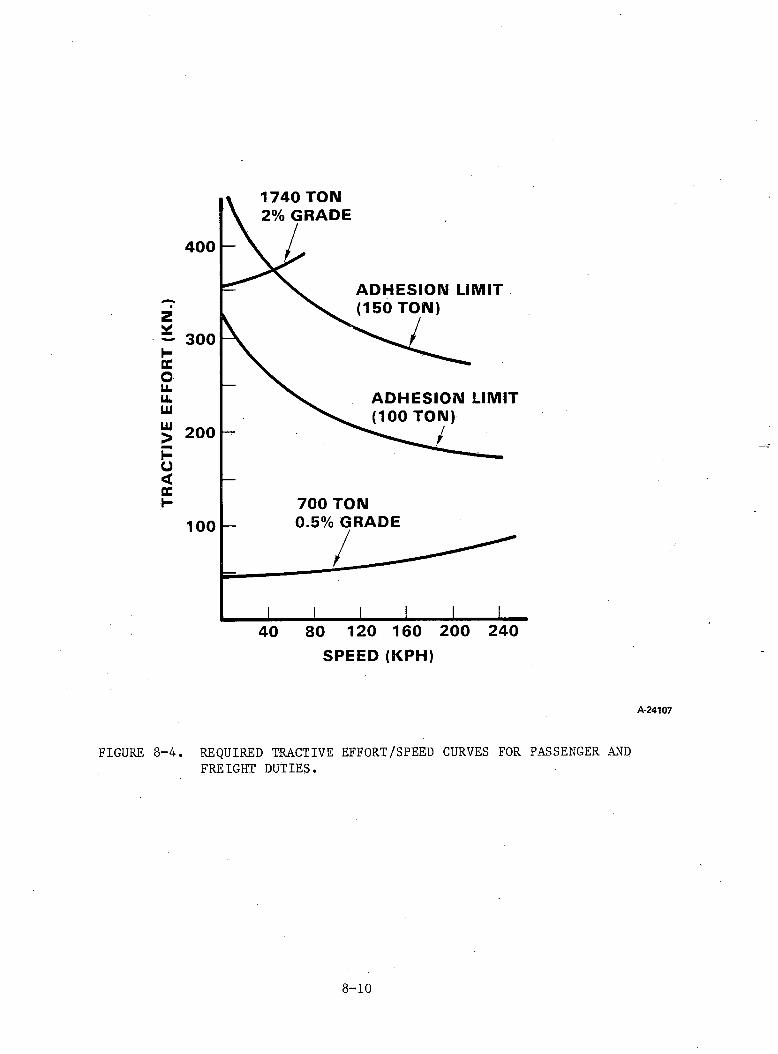
TRA
CTI
VE
EF
FO
RT
(KIM
.)
A-24107
FIGURE 8-4. REQUIRED TRACTIVE EFFORT/SPEED CURVES FOR PASSENGER AND FREIGHT DUTIES.
8-10
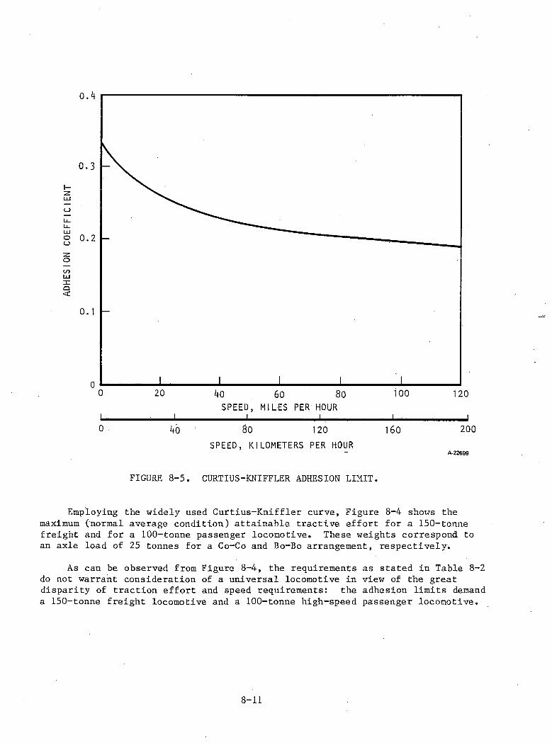
o.4
0 20 40 60 80 ioo 120SPEED, MILES PER HOUR
1 - 1 1 ' 1 ~ 10 40 80 120 160 200
SPEED, KILOMETERS PER HOURA -2 2 6 9 9
FIGURE 8-5. CURTIUS-KNIFFLER ADHESION LIMIT.
Employing the widely used Curtius-Kniffler curve, Figure 8-4 shows the maximum (normal average condition) attainable tractive effort for a 150-tonne freight and for a 100-tonne passenger locomotive. These weights correspond to an axle load of 25 tonnes for a Co-Co and Bo-Bo arrangement, respectively.
As can be observed from Figure 8-4, the requirements as stated in Table 8-2 do not warrant consideration of a universal locomotive in view of the great disparity of traction effort and speed requirements: the adhesion limits demanda 150-tonne freight locomotive and a 100-tonne high-speed passenger locomotive.
8-11
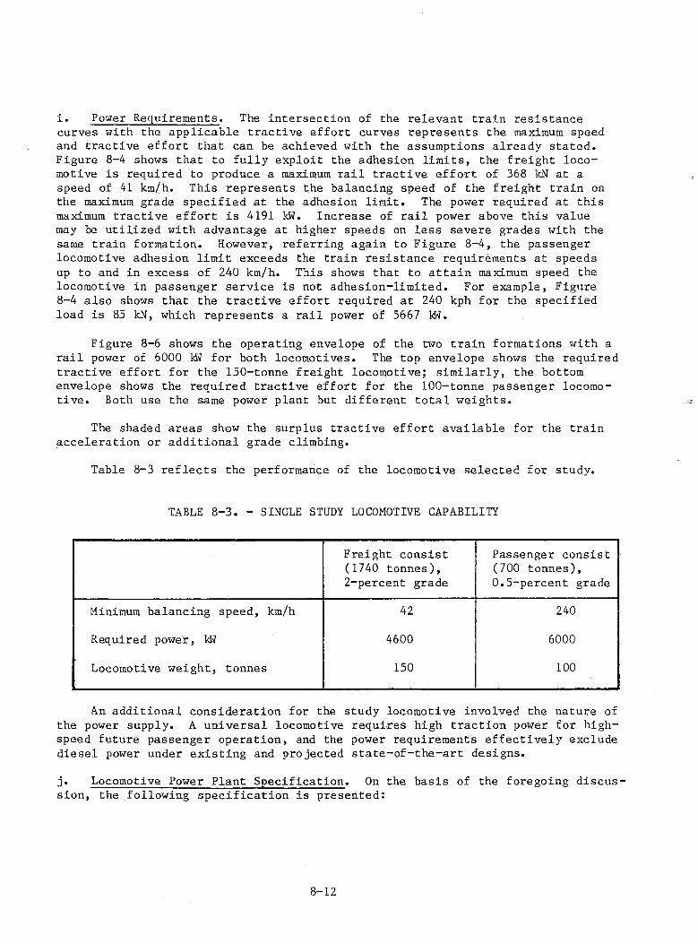
i. Power Requirements. The intersection of the relevant train resistance curves with the applicable tractive effort curves represents the maximum speed and tractive effort that can be achieved with the assumptions already stated. Figure 8-4 shows that to fully exploit the adhesion limits, the freight locomotive is required to produce a maximum rail tractive effort of 368 kN at a speed of 41 km/h. This represents the balancing speed of the freight train on the maximum grade specified at the adhesion limit. The power required at this maximum tractive effort is 4191 kW. Increase of rail power above this value may be utilized with advantage at higher speeds on less severe grades with the same train formation. However, referring again to Figure 8-4, the passenger locomotive adhesion limit exceeds the train resistance requirements at speeds up to and in excess of 240 km/h. This shows that to attain maximum speed the locomotive in passenger service is not adhesion-limited. For example, Figure8-4 also shows that the tractive effort required at 240 kph for the specified load is 85 kN, which represents a rail power of 5667 kW.
Figure 8-6 shows the operating envelope of the two train formations with a rail power of 6000 kW for both locomotives. The top envelope shows the required tractive effort for the 150-tonne freight locomotive; similarly, the bottom envelope shows the required tractive effort for the 100-tonne passenger locomotive. Both use the same power plant but different total weights.
The shaded areas show the surplus tractive effort available for the train acceleration or additional grade climbing.
Table 8-3 reflects the performance of the locomotive selected for study.
TABLE 8-3. - SINGLE STUDY LOCOMOTIVE CAPABILITY
Freight consist (1740 tonnes),
Passenger consist (700 tonnes),
2-percent grade 0.5-percent grade
Minimum balancing speed, km/h 42 240
Required power, kW 4600 6000
Locomotive weight, tonnes 150 100
An additional consideration for the study locomotive involved the nature of the power supply. A universal locomotive requires high traction power for highspeed future passenger operation, and the power requirements effectively exclude diesel power under existing and projected state-of-the-art designs.
j. Locomotive Power Plant Specification. On the basis of the foregoing discussion, the following specification is presented:
8-12

TRA
CTI
VE
EF
FO
RT
(kN
)
A-24108
FIGURE 8-6. PERFORMANCE ENVELOPES
8-13

TABLE 8-4. - LOCOMOTIVE POWER PLANT SPECIFICATION
Locomotive
Freight Passenger
Primary voltage, kV* (60-Hz, single-phase)
Nominal 25 25Maximum 27.5 27.5Minimum (continuous) 20 20Minimum (short term) 17.5 17.5
Maximum continuous rail
Power, kw 6000 6000Maximum tractive effort 450 320
at start, kNMaximum locomotive speed, km/h 160 240Minimum speed on ruling 40 -
grade, km/h
Approximate weights
Maximum locomotive, tonnes 150 100Wheel arrangement Co-Co Bo-BoMaximum weight per axle, tonnes 25 25
Additional requirements
Unsprung mass, tonnes/axle 2.0 2.0Motor suspension frame frame
suspended suspendedMotor control individual individual
axle axleWheel diameter, mm 1150 1150
* IEEE American standard for rotating electrical machines
Because of the vast operating differences in the U.S. between freight and passenger service, it is not possible to obtain a true universal locomotive. This specification allows the same power plant, but a different truck and tonne weight, to obtain as standard a locomotive as is possible.
8-14
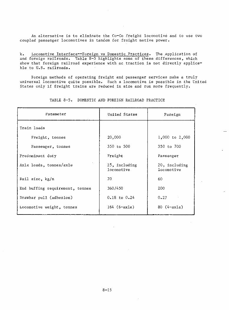
An alternative is to eliminate the Co-Co freight locomotive and to use two coupled passenger locomotives in tandem for freight motive power.
k. Locomotive Interface— Foreign vs Domestic Practices. The application of and foreign railroads. Table 8-5 highlights some of these differences, which show that foreign railroad experience with ac traction is not directly applicable to U.S. railroads.
Foreign methods of operating freight and passenger services make a truly universal locomotive quite possible. Such a locomotive is possible in the United States only if freight trains are reduced in size and run more frequently.
TABLE 8-5. DOMESTIC AND FOREIGN RAILROAD PRACTICE
Parameter United States Foreign
Train loads
Freight, tonnes 2 0 , 0 0 0 1 , 0 0 0 to 2 , 0 0 0
Passenger, tonnes 350 to 500 350 to 700Predominant duty Freight PassengerAxle loads, tonnes/axle 25, including
locomotive2 0 , including locomotive
Fail size, kg/m 70 60End buffing requirement, tonnes 360/450 200
Drawbar pull (adhesion) 0.18 to 0.24 0.27Locomotive weight, tonnes 164 (6-axle) 80 (4-axle)
8-15
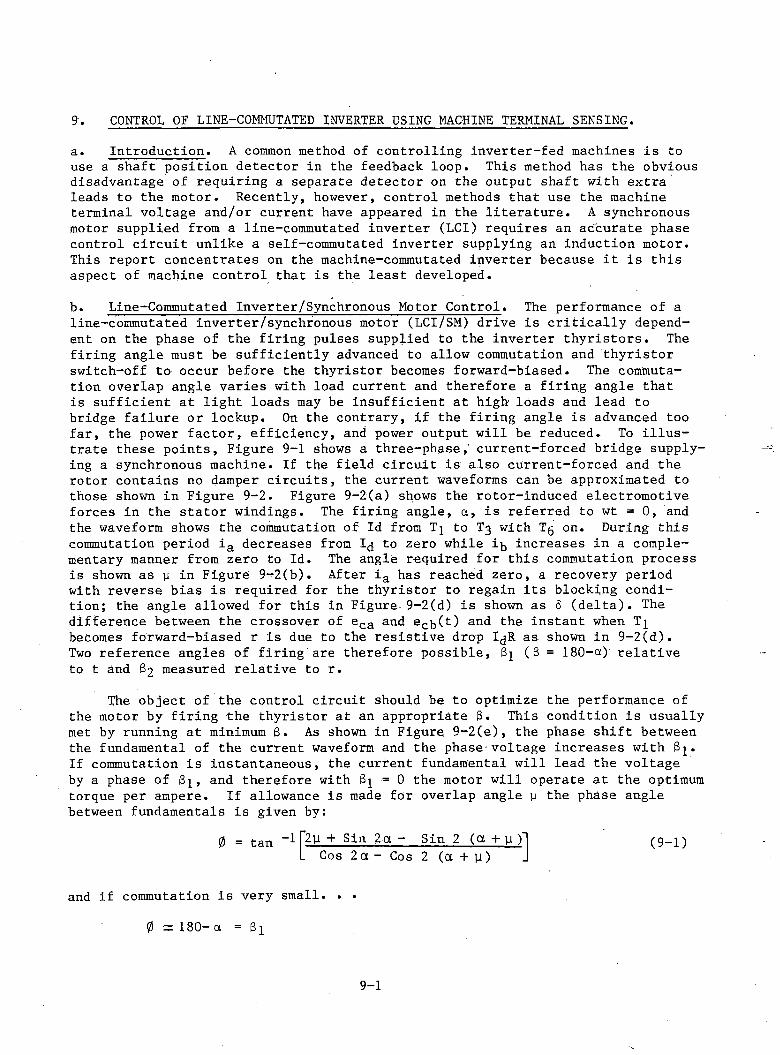
a. Introduction. A common method of controlling inverter-fed machines is to use a shaft position detector in the feedback loop. This method has the obvious disadvantage of requiring a separate detector on the output shaft with extra leads to the motor. Recently, however, control methods that use the machine terminal voltage and/or current have appeared in the literature. A synchronous motor supplied from a line-commutated inverter (LCI) requires an accurate phase control circuit unlike a self-commutated inverter supplying an induction motor. This report concentrates on the machine-commutated inverter because it is this aspect of machine control that is the least developed.b. Line-Commutated Inverter/Synchronous Motor Control. The performance of a line-commutated inverter/synchronous motor (LCI/SM) drive is critically dependent on the phase of the firing pulses supplied to the inverter thyristors. The firing angle must be sufficiently advanced to allow commutation and thyristor switch-off to occur before the thyristor becomes forward-biased. The commutation overlap angle varies with load current and therefore a firing angle that is sufficient at light loads may be insufficient at high loads and lead to bridge failure or lockup. On the contrary, if the firing angle is advanced too far, the power factor, efficiency, and power output will be reduced. To illustrate these points, Figure 9-1 shows a three-phase,' current-forced bridge supplying a synchronous machine. If the field circuit is also current-forced and the rotor contains no damper circuits, the current waveforms can be approximated to those shown in Figure 9-2. Figure 9-2(a) shows the rotor-induced electromotive forces in the stator windings. The firing angle, ct, is referred to wt =0, and the waveform shows the commutation of Id from Tj to T3 with T5 on. During this commutation period ia decreases from 1^ to zero while i^ increases in a complementary manner from zero to Id. The angle required for this commutation process is shown as p in Figure 9-2(b). After ia has reached zero, a recovery period with reverse bias is required for the thyristor to regain its blocking condition; the angle allowed for this in Figure 9-2(d) is shown as 6 (delta). The difference between the crossover of eca and ecb(t) and the instant when Tj becomes forward-biased r is due to the resistive drop I^R as shown in 9-2(d).Two reference angles of firing are therefore possible, 3 (3 = 180-ct) relative to t and $2 measured relative to r.
The object of the control circuit should be to optimize the performance of the motor by firing the thyristor at an appropriate 3. This condition is usually met by running at minimum 6 . As shown in Figure 9-2(e), the phase shift between the fundamental of the current waveform and the phase voltage increases with S . If commutation is instantaneous, the current fundamental will lead the voltage by a phase of Bj, and therefore with 3 = 0 the motor will operate at the optimum torque per ampere. If allowance is made for overlap angle p the phase angle between fundamentals is given by:
9. CONTROL OF LINE-COMMUTATED INVERTER USING MACHINE TERMINAL SENSING.
(9-1)
and if commutation is very small0 = 180- a = 81
9-1
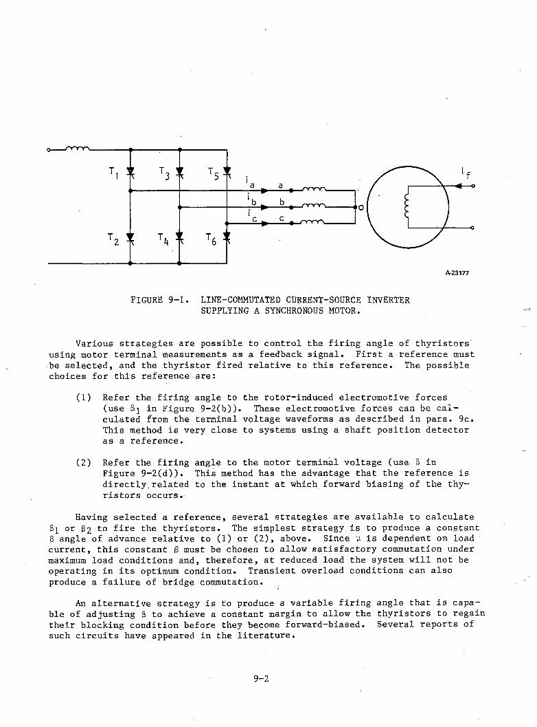
FIGURE 9-1. LINE-COMMUTATED CURRENT-SOURCE INVERTER SUPPLYING A SYNCHRONOUS MOTOR.
Various strategies are possible to control the firing angle of thyristors using motor terminal measurements as a feedback signal. First a reference must be selected, and the thyristor fired relative to this reference. The possible choices for this reference are:
(1) Refer the firing angle to the rotor-induced electromotive forces (use Si in Figure 9—2(b)). These electromotive forces can be calculated from the terminal voltage waveforms as described in para. 9c. This method is very close to systems using a shaft position detector as a reference.
(2) Refer the firing angle to the motor terminal voltage (use 3 in Figure 9-2(d)). This method has the advantage that the reference is directly.related to the instant at which forward biasing of the thyristors occurs.
Having selected a reference, several strategies are available to calculate 3i or 62 to fire the thyristors. The simplest strategy is to produce a constant 3 angle of advance relative to (1) or (2), above. Since y is dependent on load current, this constant 6 must be chosen to allow satisfactory commutation under maximum load conditions and, therefore, at reduced load the system will not be operating in its optimum condition. Transient overload conditions can also produce a failure of bridge commutation.
An alternative strategy is to produce a variable firing angle that is capable of adjusting 3 to achieve a constant margin to allow the thyristors to regain their blocking condition before they become forward-biased. Several reports of such circuits have appeared in the literature.
9-2
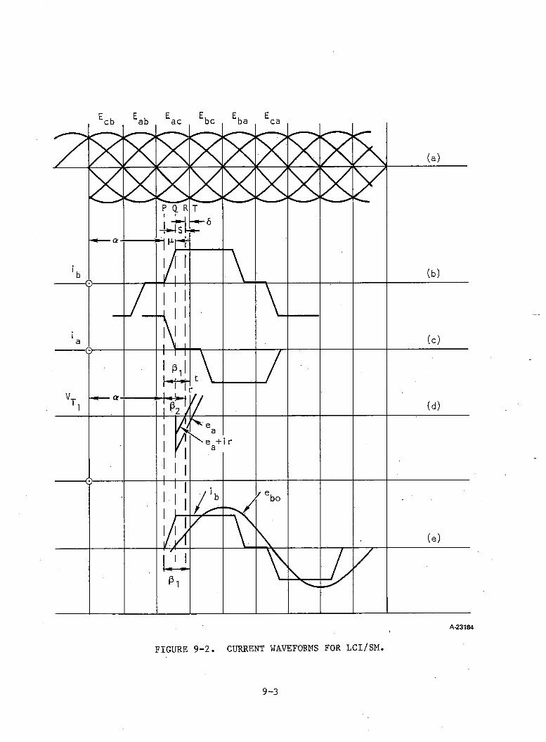
9-3
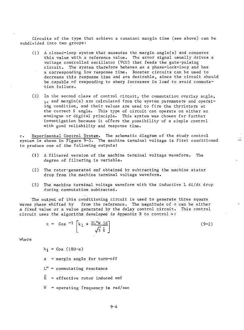
Circuits of the type that achieve a constant margin time (see above) can be subdivided into two groups:
(1) A closed-loop system that measures the margin angle(s) and compares this value with a reference value. The error signal usually drives a voltage controlled o scilla to r (VCO) that feeds the gate-pulsing c ir c u it . The system therefore behaves as a phase-lock-loop and hasa corresponding low response time. Booster c ircu its can be used to decrease this response time and are desirable, since the c ircu it should be capable of responding to sharp increases in load to avoid commutation fa ilu re .
(2) In the second class of control c irc u it, the commutation overlap angle, p, and margin(s) are calculated from the system parameters and operating condition, and th eir values are used to f ire the thyristors atthe correct 3 angle. This type of c ircu it can operate on either an analogue or d igital principle. This system was chosen for further investigation because i t offers the possibility of a simple control with good re lia b ility and response time.
c . Experimental Control System. The schematic diagram of the study control system is shown in Figure 9-3 . The machine terminal voltage is f i r s t conditioned to produce one of the following outputs:
(1) A filte red version of the machine terminal voltage waveform. The degree of f ilte rin g is variable.
(2) The rotor-generated emf obtained by subtracting the machine stato r drop from the machine terminal voltage waveform.
(3) The machine terminal voltage waveform with the inductive L di/dt drop during commutation subtracted.
The output of th is conditioning c ircu it is used to generate three square waves phase shifted by from the reference. The magnitude of a can be either a fixed value or a value generated by the delay control c ir c u it . This control circu it uses the algorithm developed in Appendix B to control a :
where
a = Cos 1 + 2L"W Id'y f i E _
(9 -2)
k = Cos (180-s)
s = margin angle for turn-off
L" = commutating reactanceAE = effectiv e rotor induced emf
W = operating frequency in rad/sec
9-4
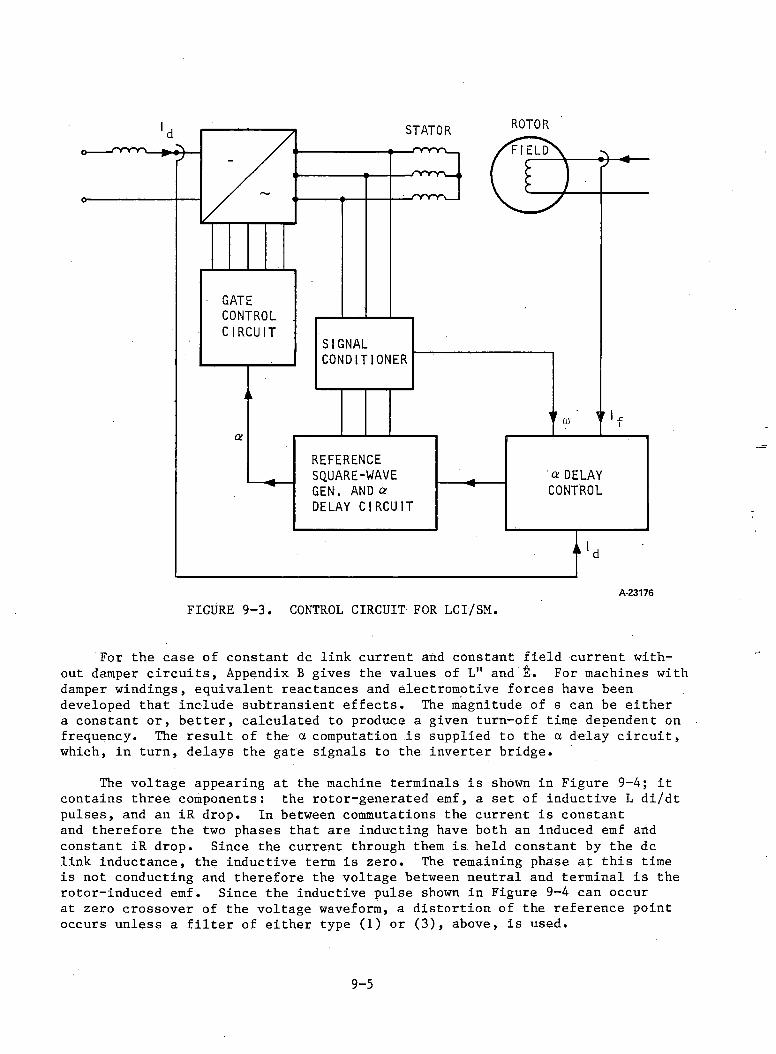
GATECONTROLCIRCUIT
a
STATOR
SIGNALCONDITIONER
REFERENCESQUARE-WAVE 'a DELAYGEN . AND or CONTROLDELAY CIRCUIT
A-23176
FIGURE 9-3 . CONTROL CIRCUIT FOR LCI/SM.
For the case of constant dc link current and constant field current without damper c ir c u its , Appendix B gives the values of L" and For machines with damper windings, equivalent reactances and electromotive forces have been developed that include subtransient e ffe c ts . The magnitude of s can be either a constant or, b e tter, calculated to produce a given turn-off time dependent on frequency. The resu lt of the a computation is supplied to the a delay c ir c u it , which, in turn, delays the gate signals to the inverter bridge.
The voltage appearing at the machine terminals is shown in Figure 9-4 ; i t contains three components: the rotor-generated emf, a set of inductive L di/dtpulses, and an iR drop. In between commutations the current is constant and therefore the two phases that are inducting have both an induced emf and constant iR drop. Since the current through them is held constant by the dc link inductance, the inductive term is zero. The remaining phase at th is time is not conducting and therefore the voltage between neutral and terminal is the rotor-induced emf. Since the inductive pulse shown in Figure 9-4 can occur at zero crossover of the voltage waveform, a distortion of the reference point occurs unless a f i l t e r of either type (1) or (3 ) , above, is used.
9-5
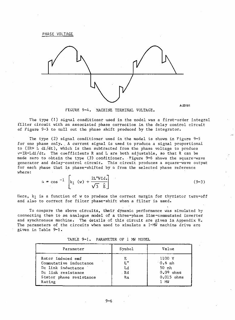
PHASE VOLTAGE
A-23181
FIGURE 9-4. MACHINE TERMINAL VOLTAGE.
The type (1) signal conditioner used in the model was a firs t-o rd er integral f i l t e r c ircu it with an associated phase correction in the delay control c ircu it of Figure 9-3 to null out the phase shift produced by the integrator.
The type (2) signal conditioner used in the model is shown in Figure 9-5 for one phase o n ly ., A current signal is used to produce a signal proportional to (IR+ L d i/d t), which is then subtracted from the phase voltage to produce v-IR-Ldi/dt. The coefficien ts R and L are both adjustable, so that R can be made zero to obtain the type (3) conditioner. Figure 9-6 shows the square-wave generator and delay-control c ircu it. This c ircu it produces a square-wave output for each phase that is phase-shifted by a from the selected phase reference where:
a = cos2L"WId.
kl (w) + r - aV 3 E
(9-3)
Here, kj is a function of w to produce the Correct margin for thyristor turn-off and also to correct for f i l te r phase-shift when a f i l te r is used.
To compare the above c ircu its , their dynamic performance was simulated by connecting them to an analogue model of a three-phase line-commutated inverter and synchronous machine. The details of this c ircu it are given in Appendix H. The parameters of the c ircu its when used to simulate a 1-MW machine drive are given in Table 9-1 .
TABLE 9-1 . PARAMETER OF 1 MW MODEL
Parameter Symbol Value
Rotor induced emf E 1100 VCommutative inductance L" 0 .6 mhDc link inductance Ld 50 mhDc link resistance . Rd 0.09 ohmsStator phase resistance Ra 0.015 ohmsRating 1 MW
9-6
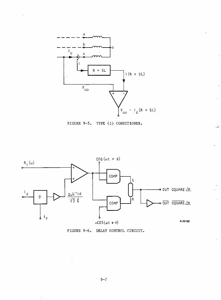
/"y-y y \
1(R + SL)
I (R + SL) c
FIGURE 9-5 . TYPE (2) CONDITIONER.
COS (cot + <j>)
-cos (tut + $)FIGURE 9-6 . DELAY CONTROL CIRCUIT.
SQUARE l°L
SQUAREZ9L
A-23185
9-7
d. Circuit Type (1) Conditioner (F irs t Order F i l t e r ) . Figure 9-7 shows the inverter machine waveforms with the type (1) signal conditioner. Trace 6 shows the single-order filte red waveform used as a reference for the b phase gate signals. I t can be seen that the filte red waveform has been phase-shifted from the terminal voltage waveform and a correction to the term in the a delay control c ircu it was made to null out this phase sh ift. The three-phase motor current is shown in traces 2 through 4 showing the conducting, overlap, and zero current sections of the cycle.
The effect of varying the delay angle, a , is shown in Figure 9-8 and the waveforms can be compared with Figure- 9-7. The two a firing angles were set at 140 deg ( 8 2 = 40 deg) and 12,1 deg ( 8 2 = 59 deg) for Figures 9-7 and 9-8, respectively, and produced overlap angles of 22 deg and 14 deg with margins of 17 deg and 45 deg, respectively. The increase in 8 2 reduces the effective operating power factor of the machine, and the resulting reduction in output torque for constant dc link currents of 600 A and 300 A is shown in Figure 9-9 . To show the advantage of a variable-delay angle system i t should be considered that the 8 angle is chosen at 600 A dc link current to correspond to point A (margin - 35 deg) with an allowance for overload. If the load torque is now reduced to point B on the 300 A dc link current curve, the phase margin increases to 45 deg. At both dc link currents, i t would be possible to increase the output torque to points D and G (which correspond to phase margins of 16 deg and 13 deg, respectively) i f the delay angle control was able to respond su fficien tly quickly to changes in load. The dynamic performance of the c ircu it using the type (1) conditioner is illu stra ted in Figure 9-10. Figure 9-10 shows the switch-on transient at 75 Hz. During this transient, expanded traces were taken to measure phase-margin(s). This value remained constant at 14 deg throughout the switch-on as can be seen from Figure 9-11, which shows the in itia l part of Figure 9-10 expanded.
The effect of various f i l te r time-constants on c ircu it performance was investigated. Figures 9-12 and 9-13 show two extremes. Figure 9-12 shows the performance with a f i l te r 3 db-point at 75 percent operating fre quency whereas Figure 9-13 shows the circu it with the 3 db-point well above operating frequency (800 percent). Figure 9-12 shows that the conditioned signal is a close approximation to a sinewave, and the k factor in the a delay circu it has been chosen to compensate for the large f i l te r phase-shift. Figure9-13, on the other hand, shows a low filte rin g performance with the L di/dt pulses producing multiple crossovers. This trace shows false triggering of the bridge due to the low filtered waveform. For a wide inverter frequency operating range, a low 3 db f i l te r corner should therefore be chosen with an appropriate phase-shift compensation in the a delay c ircu it.
e. Circuit with Type (2) Conditioner. The above f i l te r method offers a simple but effective method of conditioning the machine terminal voltage. An altern ative method is to subtract the L di/dt pulses from the machine terminal voltage. These have been shown in Figure 9-13 to produce multiple false thyristor trig g ering. This method has the advantage of completely eliminating the L di/dt pulse at a ll load currents without producing a phase shift to the terminal voltage.Figure 9-2 shows that to avoid commutation failu re , the margin s should be measured relative to the terminal line voltage crossover. Since the bridge is current- forced, L/di dt is zero between commutations and the iR drop is the only relevant
9-8
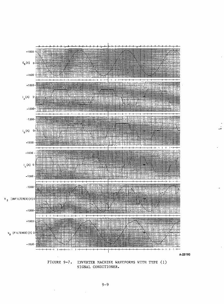
p—p—p—p—p—p—p—i,—p—P—P—P—p—p—p—p—p—t—p— i—p—p—p—p—p—p—p—t,—p—p—p—P— P— P— P— P— P— k— P-<■1000
E„(V) 0
-1000
+ 1000
1 (A) 0-
-1000
+ 1000-
i b (A) 0-
-1000
+1000
1 (A) 0
-1000 -
+ 1000-
Vg (UNFILTERED)(V)0
-1000-
+1000-
V0 (FILTERED)(V) 0D
-1000-
A-23193
FIGURE 9-7. INVERTER MACHINE WAVEFORMS WITH TYPE (1)SIGNAL CONDITIONER.
9-9
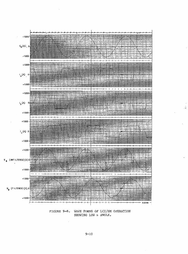
+1000l
Er(v)I, 0,
VB (UNF I LTERED) (V) 0
V„ (FILTERED) (V), 0 o
FIGURE 9-8. WAVE FORMS OF LCI/SM OPERATION SHOWING LOW a ANGLE.
9-10
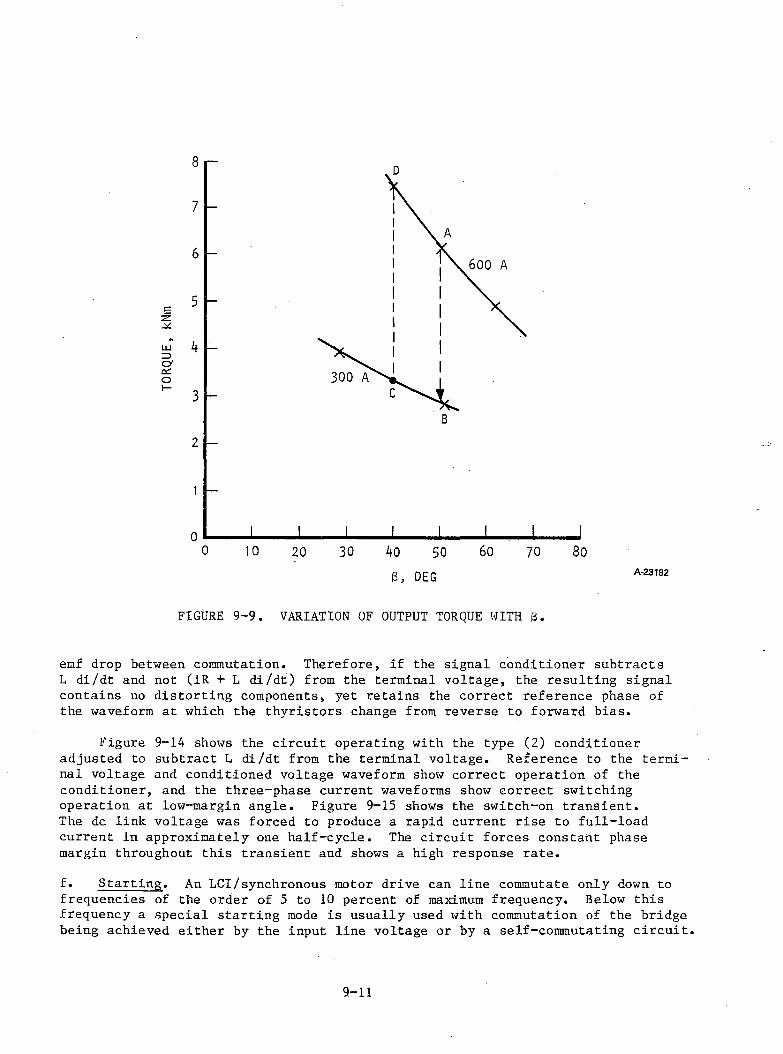
FIGURE 9-9. VARIATION OF OUTPUT TORQUE WITH B.
emf drop between commutation. Therefore, if the signal conditioner subtracts L di/dt and not (iR + L di/dt) from the terminal voltage, the resulting signal contains no distorting components, yet retains the correct reference phase of the waveform at which the thyristors change from reverse to forward bias.
Figure 9-14 shows the circuit operating with the type (2) conditioner adjusted to subtract L di/dt from the terminal voltage. Reference to the terminal voltage and conditioned voltage waveform show correct operation of the conditioner, and the three-phase current waveforms show correct switching operation at low-margin angle. Figure 9-15 shows the switch-on transient.The dc link voltage was forced to produce a rapid current rise to full-load current in approximately one half-cycle. The circuit forces constant phase margin throughout this transient and shows a high response rate.f. Starting. An LCI/synchronous motor drive can line commutate only down to frequencies of the order of 5 to 10 percent of maximum frequency. Below this frequency a special starting mode is usually used with commutation of the bridge being achieved either by the input line voltage or by a self-commutating circuit.
9 - 1 1
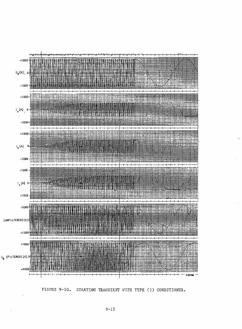
+1000
EB(V)i 0,
-1000
+1000
i (a ) 0
-1000
+ 1000
'bw
-1000
FIGURE 9-10. STARTING TRANSIENT WITH TYPE (1) CONDITIONER
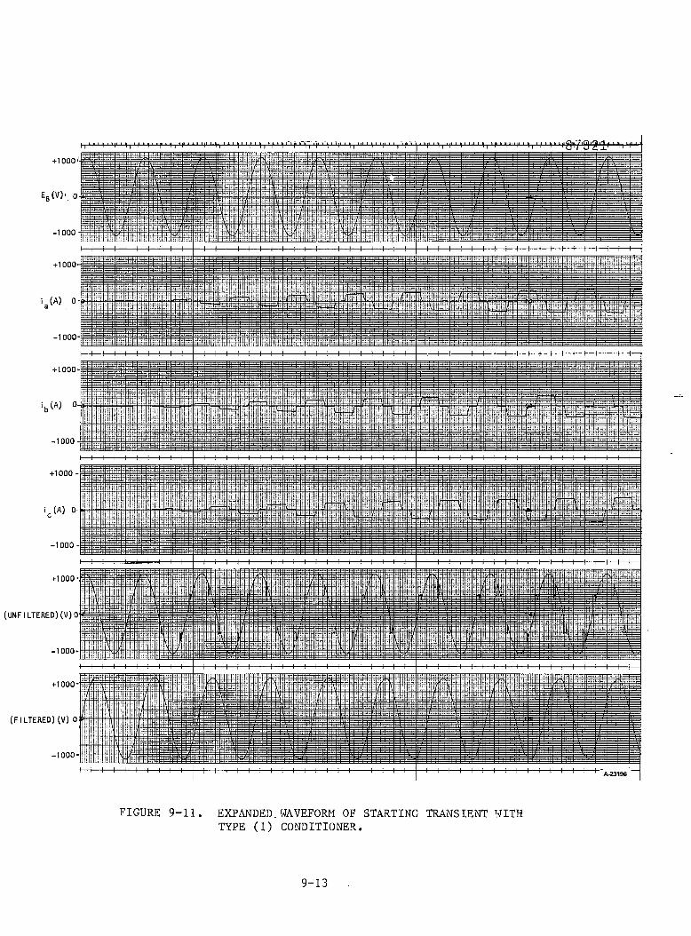
I1 1 1 I 'I' M “l‘ H I 'I' M‘ 111 "I I M“ 1' ■llQll7'Ql2'l|‘ M I ‘ t*+ 1000
Eb (V)', 0:
-1000 ■
+1000
i (a ) O-l
-1000-
+ 1000
i b (A) 0-|
-1000 -!
+1000 -
i (A) 0
-1000 -
+1000
(UNFILTERED)(V)0
-1000-
+1000-
(FILTERED)(V) 0
-1000-
FIGURE 9-11. EXPANDED.WAVEFORM OF STARTING TRANSIENT WITH TYPE (1) CONDITIONER.
9-13
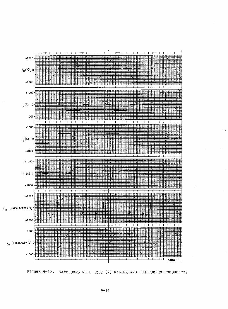
+1000'-
E=(V)i. 0,
-1000
+1000-
i (A) 0
-1000
+1000-
i b (A) 0.
-1000 -
+1000 -
i (A) 0
-1000 -
+1000
V B (UNF I LTERED) (V) 0
-1000-
+ 1000
V„ (FILTERED) (V).OD
-1000
FIGURE 9-12. WAVEFORMS WITH TYPE (2) FILTER AND LOW CORNER FREQUENCY.
9-14
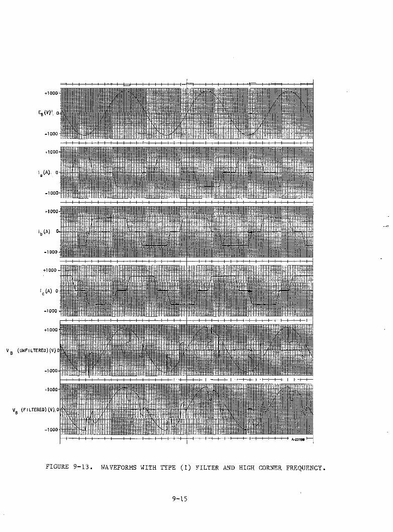
+ 1000
E„(v)! 0,
VB (UNFILTERED) (V) 0
V (FILTERED) (V),0
-1000I----- 1------1------1------1----- 1------1------1------1----- 1----- 1------1----- 1------1----- i------I" A-23198 I------1
FIGURE 9-13. WAVEFORMS WITH TYPE (1) FILTER AND HIGH CORNER FREQUENCY.
9-15
With the present control system the circuit is unable to detect rotor position until shaft rotation occurs. One solution to this problem is to program the first few cycles of the inverter to slowly accelerate in an open loop in condition until the feedback circuit produces a lock-in signal. The analogue simulator was not able to simulate the mechanical inertial and friction effects and a startup control waveform was therefore not attempted.
g. Conclusions. Three circuits to control an LCI/synchronous machine set were successfully tested. Two of the circuits use the machine terminal voltage to produce a gate control circuit that automatically varies the bridge-delay-angle to achieve a predetermined reverse bias margin for the thyristors; the third method produces a constant delay angle. The first of these circuits used a first-order integrator filter with corresponding phaseshift correction; the second circuit used a summing amplifier to subtract the inductive pulses present in the machine terminal voltages. Both circuits were able to operate successfully during switch-on transients and variable-load steady-state conditions.
The alternative to the automatic variation of a is to use a fixed ct with a corresponding reduction in machine performance.
9 - 1 6
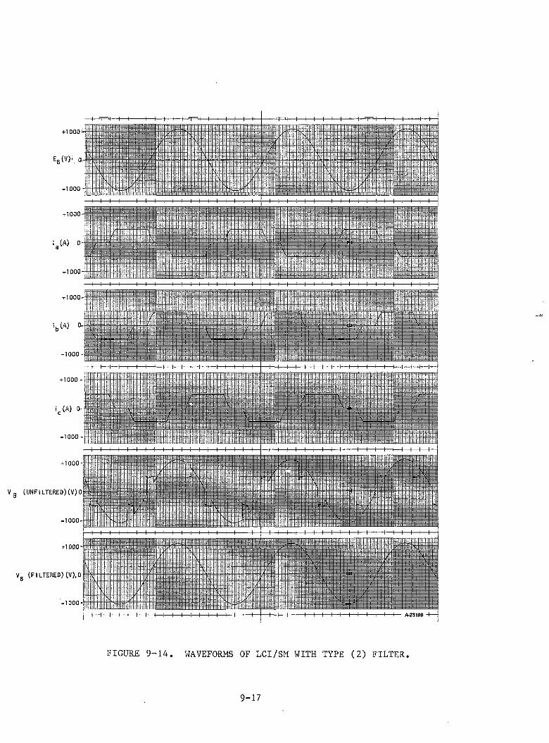
I H—M— !— I 1 1 1— !— I \ T^l— i— I— I— f-+1000^-
Eb(v) ’, 0,
-1000
+1000
i (A) 0 -
-1000
+ 1000
ib (A) 0.
-1000
+1000 -
i (A) 0-
-1000 -
-i— I— I— I— I— I— I— I— I— I— I— I— I— I— I— I— I— I-
-I-1-1-1-1-1-1-1-1-1-1-1-1-1-h—I-1-1-
-I— I— I— I— I— I— i— I— I— I— I— I— I— I— I— I— I— ]— I-
-1— I— I— I— I—H— I— I— I-
+1000
V g (UNFI LTERED) (V) Op
-1000'
+1000-
V„ (FILTERED) (V),0D
-1000-
-i— l— I— I— I— I— l— l— I— l— I— I— l— f-
H— I— I— !— I— I-1— i— I— I— I— !— I— I— l— I— {— I— h-
H— !-—I— i— !— I— i— i— l— I— I— i— I— I— i— I— I— !— h-
H— l— I— I— I— I— h-
H— !— I— I— i— i— I—4—
H -------1-------1-------1-------1-------1-------i-------!-------1-------1-------1-------1-------1----- 1— A-23199 •
FIGURE 9-14. WAVEFORMS OF LCI/SM WITH TYPE (2) FILTER.
9 - 1 7
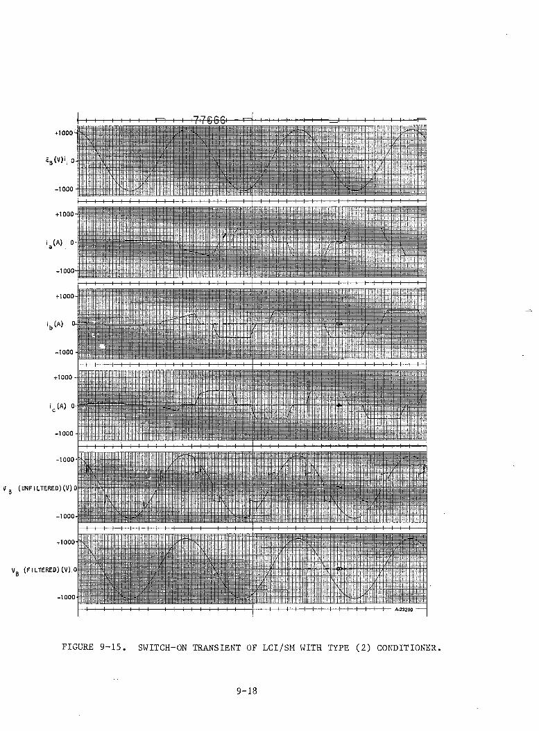
+1000
E„(V)i 0,
-1000
+1000
i (A ) 0
-1000
+ 1000
i b (A) 0.
-1000
+1000 -
i (A) 0
-1000
+1000
V B (UNFILTERED)(V)0
-1000-
+1000
V- (FILTERED) (V),0D
-1000
FIGURE 9-15. SWITCH-ON TRANSIENT OF LCI/SM WITH TYPE (2) CONDITIONER.
9-18
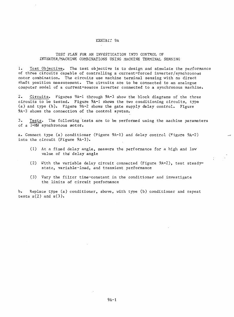
EXHIBIT 9A
TEST PLAN FOR AN INVESTIGATION INTO CONTROL OF INVERTER/MACHINE COMBINATIONS USING MACHINE TERMINAL SENSING
1. Test Objective. The test objective is to design and simulate the performance of three circu its capable of controlling a current-forced inverter/synchronous motor combination. The c ircu its use machine terminal sensing with no direct shaft position measurement. The circu its are to be connected to an analogue computer model of a current-source inverter connected to a synchronous machine.
2. C ircu its. Figures 9A-1 through 9A-3 show the block diagrams of the three circu its to be tested. Figure 9A-1 shows the two conditioning c ircu its , type(a) and type (b). Figure 9A-2 shows the gate supply delay control. Figure 9A-3 shows the connection of the control system.
3. Tests. The following tests are to be performed using the machine parameters of a 1-MW synchronous motor.
a. Connect type (a) conditioner (Figure 9A-1) and delay control (Figure 9A-2) into the c ircu it (Figure 9A-3).
(1) At a fixed delay angle, measure the performance for a high and low value of the delay angle
(2) With the variable delay circu it connected (Figure 9A-2), test steady- sta te , variable-load, and transient performance
(3) Vary the f i l t e r time-constant in the conditioner and investigate the limits of c ircu it performance
b. Replace type (a) conditioner, above, with type (b) conditioner and repeat tests a(2) and a (3 ) .
9A-1
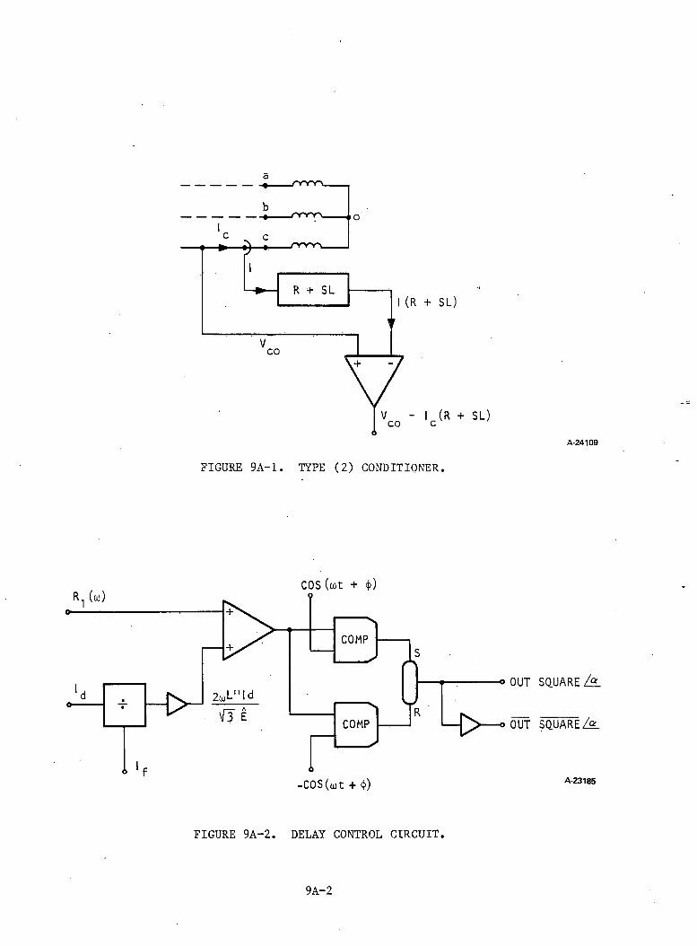
(R + SL)
FIGURE 9A-1. TYPE (2) CONDITIONER.
-COS (ojt + <(>)
OUT
OUT
FIGURE 9A-2. DELAY CONTROL CIRCUIT.
A-24109
SQUARE i S L
SQUARED
A-23185
9 A - 2
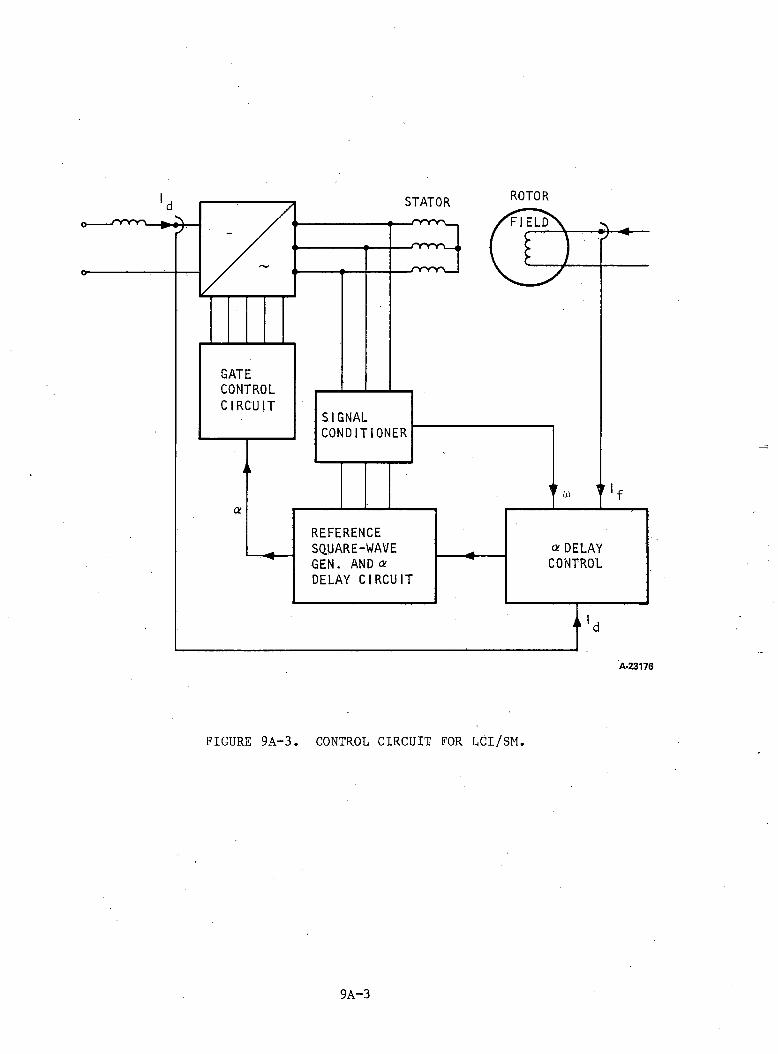
STATOR ROTOR
GATECONTROLCIRCUIT
n
SIGNALCONDITIONER
a
“'d
A-23176
FIGURE 9A-3. CONTROL CIRCUIT FOR LCI/SM.
9A-3
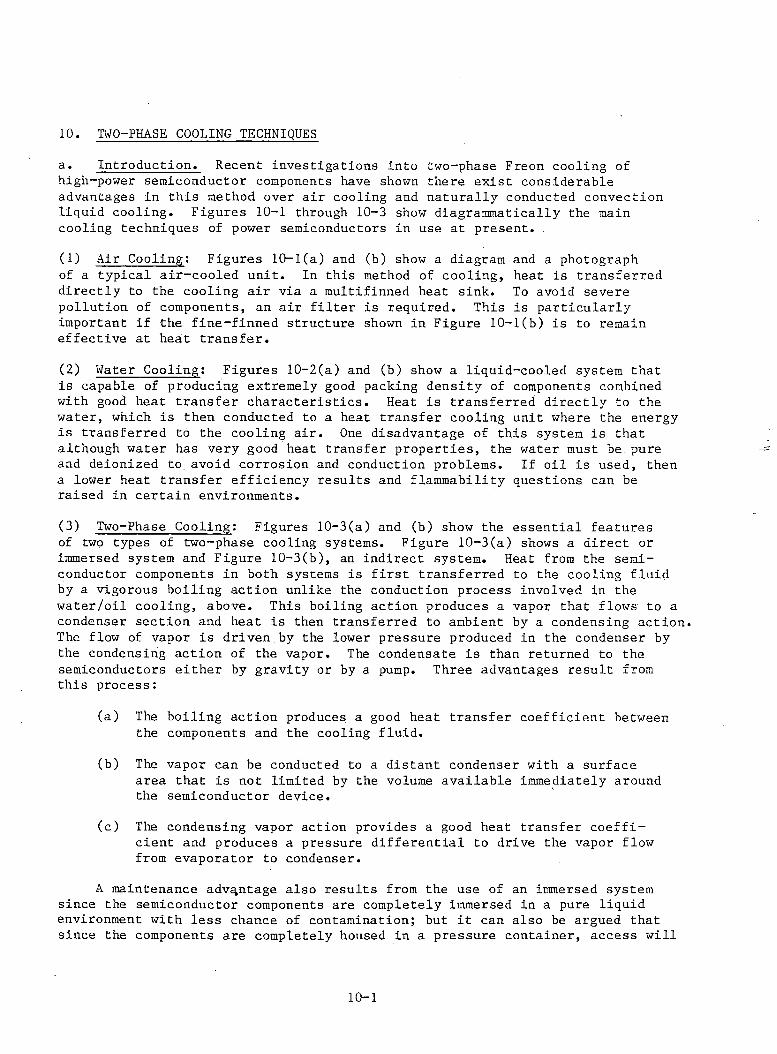
10. TWO-PHASE COOLING TECHNIQUESa. Introduction. Recent investigations into two-phase Freon cooling of high-power semiconductor components have shown there exist considerable advantages in this method over air cooling and naturally conducted convection liquid cooling. Figures 10-1 through 10-3 show diagrammatically the main cooling techniques of power semiconductors in use at present.(1) Air Cooling: Figures 10-1(a) and (b) show a diagram and a photographof a typical air-cooled unit. In this method of cooling, heat is transferred directly to the cooling air via a multifinned heat sink. To avoid severe pollution of components, an air filter is required. This is particularly important if the fine-finned structure shown in Figure 10-1(b) is to remain effective at heat transfer.(2) Water Cooling: Figures 10-2(a) and (b) show a liquid-cooled system thatis capable of producing extremely good packing density of components combined with good heat transfer characteristics. Heat is transferred directly to the water, which is then conducted to a heat transfer cooling unit where the energy is transferred to the cooling air. One disadvantage of this system is that although water has very good heat transfer properties, the water must be, pure and deionized to. avoid corrosion and conduction problems. If oil is used, then a lower heat transfer efficiency results and flammability questions can be raised in certain environments.(3) Two-Phase Cooling: Figures 10-3(a) and (b) show the essential featuresof two types of two-phase cooling systems. Figure 10-3(a) shows a direct or immersed system and Figure 10-3(b), an indirect system. Heat from the semiconductor components in both systems is first transferred to the cooling fluid by a vigorous boiling action unlike the conduction process involved in the water/oil cooling, above. This boiling action produces a vapor that flows to a condenser section and heat is then transferred to ambient by a condensing action. The flow of vapor is driven by the lower pressure produced in the condenser by the condensing action of the vapor. The condensate is than returned to the semiconductors either by gravity or by a pump. Three advantages result from this process:
(a) The boiling action produces a good heat transfer coefficient between the components and the cooling fluid.
(b) The vapor can be conducted to a distant condenser with a surface area that is not limited by the volume available immediately around the semiconductor device.
(c) The condensing vapor action provides a good heat transfer coefficient and produces a pressure differential to drive the vapor flow from evaporator to condenser.
A maintenance advantage also results from the use of an immersed system since the semiconductor components are completely immersed in a pure liquid environment with less chance of contamination; but it can also be argued that since the components are completely housed in a pressure container, access will
10-1

FINNED HEAT SINKS
b. TYPICAL AIR-COOLED SYSTEM F35460
FIGURE 10-1. AIR COOLING OF SEMICONDUCTORS.
10-2
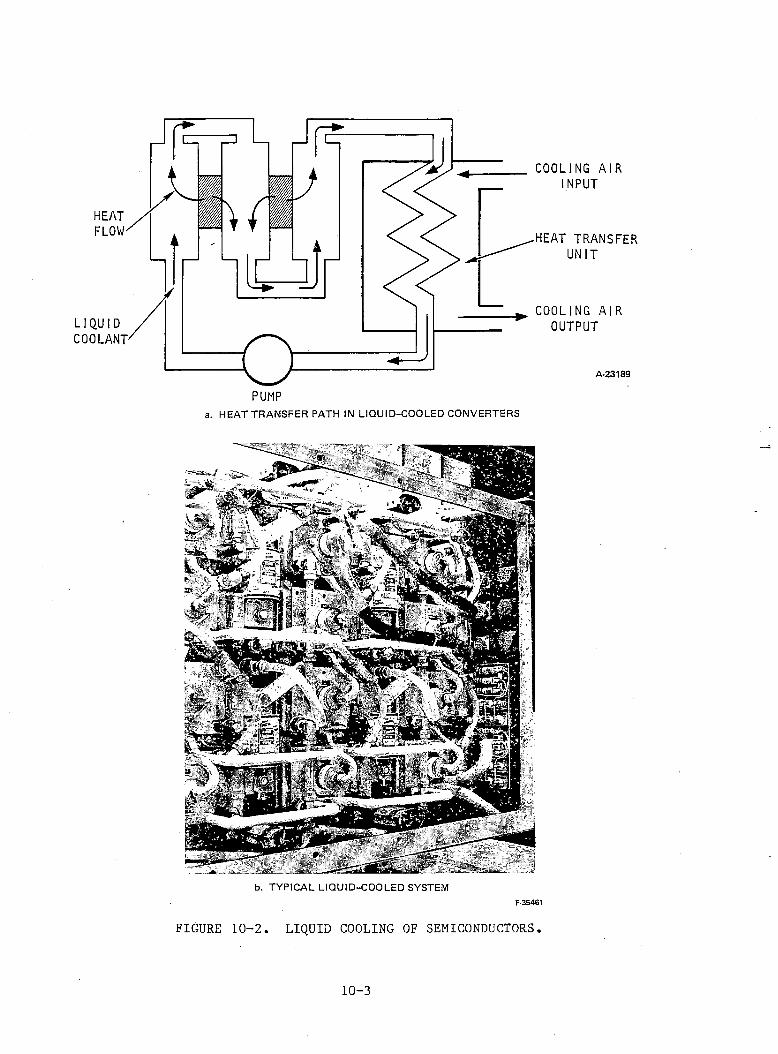
HEATFLOW
IWaPUMP
COOLING AIR INPUT
HEAT TRANSFER UNIT
COOLING AIROUTPUT
A-23189
a. HEAT TRANSFER PATH IN LIQUID-COOLED CONVERTERS
b. TYPICAL LIQUID-COOLED SYSTEMF-35461
FIGURE 10-2. LIQUID COOLING OF SEMICONDUCTORS.
10-3
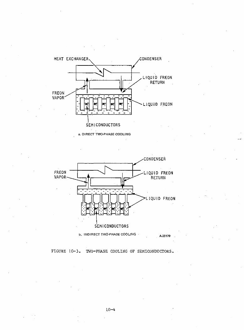
HEAT EXCHANGER ■CONDENSER
LIQUID FREON RETURN
■LIQUID FREON
FIGURE 10-3. TWO-PHASE COOLING OF SEMICONDUCTORS.
10-4
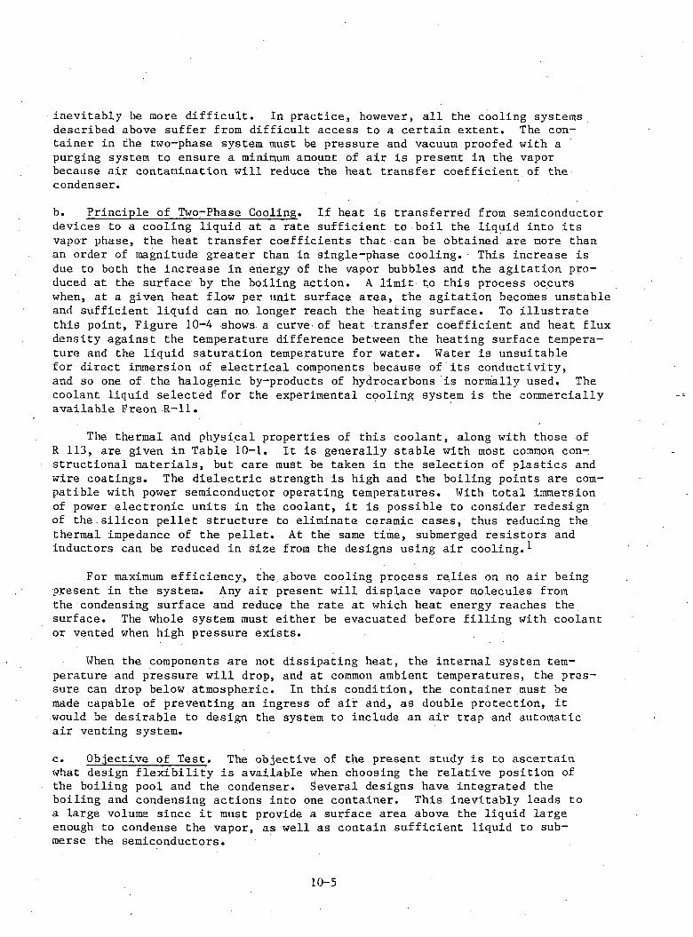
inevitably be more difficult. In practice, however, all the cooling systems described above suffer from difficult access to a certain extent. The container in the two-phase system must be pressure and vacuum proofed with a purging system to ensure a minimum amount of air is present in the vapor because air contamination will reduce the heat transfer coefficient of the condenser.b. Principle of Two-Phase Cooling. If heat is transferred from semiconductor devices to a cooling liquid at a rate sufficient to boil the liquid into its vapor phase, the heat transfer coefficients that can be obtained are more than an order of magnitude greater than in single-phase cooling. This increase is due to both the increase in energy of the vapor bubbles and the agitation produced at the surface by the boiling action. A limit to this process occurs when, at a given heat flow per unit surface area, the agitation becomes unstable and sufficient liquid can no. longer reach the heating surface. To illustrate this point, Figure 10-4 shows a curve' of heat transfer coefficient and heat flux density against the temperature difference between the heating surface temperature and the liquid saturation temperature for water. Water is unsuitablefor direct immersion of electrical components because of its conductivity, and so one of the halogenic by-products of hydrocarbons is normally used. The coolant liquid selected for the experimental cooling system is the commercially available Freon R-ll.
The thermal and physical properties of this coolant, along with those of R 113, are given in Table 10-1. It is generally stable with most common constructional materials, but care must be taken in the selection of plastics and wire coatings. The dielectric strength is high and the boiling points are compatible with power semiconductor operating temperatures. With total immersion of power electronic units in the coolant, it is possible to consider redesign of the silicon pellet structure to eliminate ceramic cases, thus reducing the thermal impedance of the pellet. At the same time, submerged resistors and inductors can be reduced in size from the designs using air cooling.^
For maximum efficiency, the above cooling process relies on no air being present in the system. Any air present will displace vapor molecules from the condensing surface and reduce the rate at which heat energy reaches the surface. The whole system must either be evacuated before filling with coolant or vented when high pressure exists.
When the components are not dissipating heat, the internal system temperature and pressure will drop, and at common ambient temperatures, the pressure can drop below,atmospheric. In this condition, the container must be made capable of preventing an ingress of air and, as double protection, it would be desirable to design the system to include an air trap and automatic air venting system.c. Objective of Test. The objective of the present study is to ascertain what design flexibility is available when choosing the relative position of the boiling pool and the condenser. Several designs have integrated the boiling and condensing actions into one container. This inevitably leads to a large volume since it must provide a surface area above the liquid large enough to condense the vapor, as well as contain sufficient liquid to submerse the semiconductors.
10-5
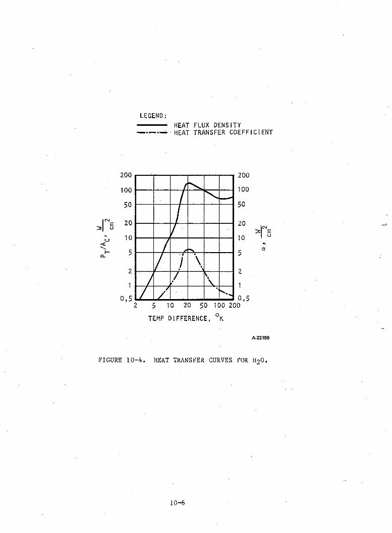
cmLEGEND:--- ■-- - HEAT FLUX DENSITY------ - HEAT TRANSFER COEFFICIENT
cs
o<N1-CL
10050
20105
21
0,5
200 200 100 50
20 10 5
2 10,52 5 10 20 50 100 200
TEMP DIFFERENCE, °K
I CM
A-23180
FIGURE 10-4. HEAT TRANSFER CURVES FOR H20.
10-6
cm
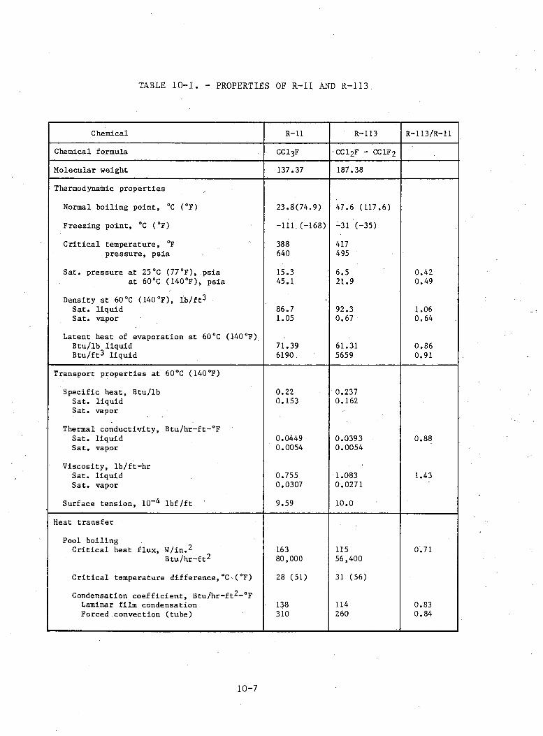
TABLE 10-1. - PROPERTIES OF R-ll AND R-113
Chemical R-ll R-113 R-113/R-11Chemical formula CC13F CC12F - CC1F2Molecular weight 137.37 187.38Thermodynamic propertiesNormal boiling point, °C (°F) 23.8(74.9) 47.6 (117.6)Freezing point, °C (°F) -111,(-168) -31 (-35)Critical temperature, °F 388 417pressure, psia 640 495Sat. pressure at 25°C (77°F), psia 15.3 6.5 0.42at 60 °C ( 140 °F), psia 45.1 21.9 0.49Density at 60°C (140°F), lb/ft2 Sat. liquid 86.7 92.3 1.06Sat. vapor 1.05 0.67 0.64Latent heat of evaporation at 60°C (140°F) Btu/lb liquid 71.39 61.31 0.86Btu/ft2 liquid 6190, 5659 0.91
Transport properties at 60°C (140°F)Specific heat, Btu/lb 0.22 0.237Sat. liquid 0.153 0.162Sat. vaporThermal conductivity, Btu/hr-ft-°FSat. liquid 0.0449 0.0393 0.88Sat. vapor 0.0054 0.0054Viscosity, lb/ft-hrSat. liquid 0.755 1.083 1.43Sat. vapor 0.0307 0.0271Surface tension, 10" lbf/ft 9.59 10.0
Heat transferPool boilingCritical heat flux, W/in. 2 163 115 0.71Btu/hr-ft2 80,000 56,400Critical temperature difference,°C (°F) 28 (51) 31 (56)Condensation coefficient, Btu/hr-ft2-°FLaminar film condensation 138 114 0.83Forced convection (tube) 310 260 0.84
10-7
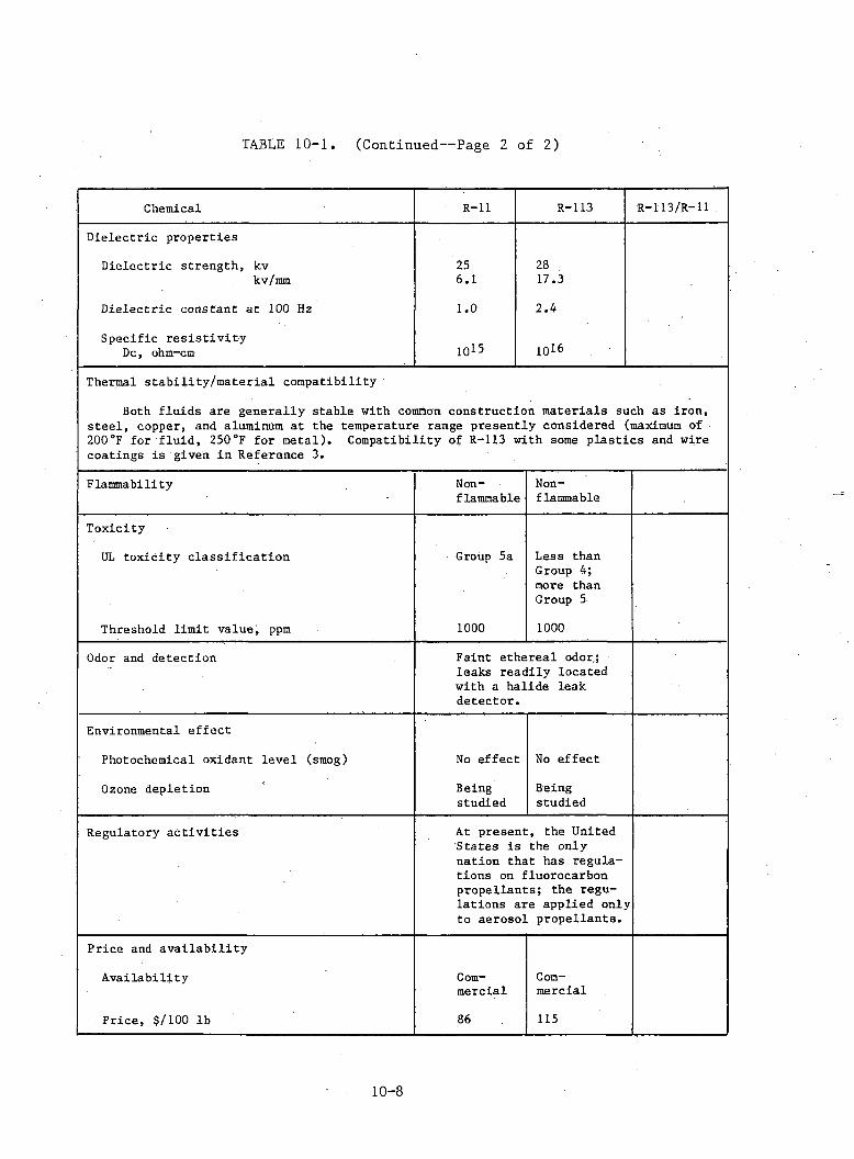
TABLE 10-1. (Continued— Page 2 of 2)
Chemical R-ll R-113 R-113/R-11.Dielectric properties Dielectric strength, kv 25 28kv/mm 6.1 17.3Dielectric constant at 100 Hz 1.0 2.4Specific resistivity Dc, ohm-cm 1015 1016
Thermal stability/material compatibilityBoth fluids are generally stable with common construction materials such as iron, steel, copper, and aluminum at the temperature range presently considered (maximum of 200°F for fluid, 250°F for metal). Compatibility of R-113 with some plastics and wire coatings is given in Reference 3.
Flammability Nonflammable NonflammableToxicityUL toxicity classification Group 5a Less than Group 4; more than Group 5Threshold limit value, ppm 1000 1000
Odor and detection Faint ethereal odor.; leaks readily located with a halide leak detector.Environmental effectPhotochemical oxidant level (smog) No effect No effectOzone depletion Beingstudied Beingstudied
Regulatory activities At present, the United States is the only nation that has regulations on fluorocarbon propellants; the regulations are applied only to aerosol propellants.Price and availabilityAvailability Commercial CommercialPrice, $/100 lb 86 115
1 0 - 8
This method, which is illustrated in Figure 10-5(a), has the advantage of simplicity of construction, but it does require cooling air to be conducted to the complete unit.
In the present experiment the two functions of boiling and condensing have been separated. This separation has the effect of reducing the size of the boiling unit since it no longer requires a condensing surface area, and also allows the condenser and air feed to be moved to a convenient location. The limitations to this system are:
(1) Pressure Drop Between Boiler and Condenser: Figure 10-5(b) showsthe Freon vapor flowing along the vapor pipe at velocity v. To achieve this flow, a pressure difference must occur between the boiler (pressure P^) and condenser (pressure Pc), where 6p = P^,-Pc. This pressure difference can be determined from the vapor velocity, v, the vapor pipe impedance, the condenser pressure drop, and the vertical displacement. If this pressure drop becomes significant, the boiler pressure increases with a resultant increase in the temperature of the coolant and, therefore, an increase in the thermal impedance of the cooling system.
(2) Height Difference: The system will operate with the condensingaction producing the required flow of vapor and with gravity producing the return flow of the condensate to the boiler, providing the condenser is at a minimum height above the boiler. If the condenser is below the boiler level, a small pump will be requiredto return the condensate to the boiler. The limit of height difference occurs when the pressure drop between condenser and boiler is large enough to support the weight of liquid in the return pipe, thereby sucking coolant into the condenser and reducing the effective surface area.
(3) Sealing Requirements: The pressure inside the system rises as theheat dissipation of the semiconductors increases, and although these pressures are not excessive, the system, in particular the pipes and couplings, must be capable of withstanding the pressure. At the same time, it is possible for the internal pressure to drop below atmospheric when no internal heat dissipation is present.
d. Description of Experimental Apparatus. Figures 10-6 and 10-7 show a photograph of the experimental test rig. Figure 10-6 shows the boiler (lower right) and condenser units (upper center) joined by the vapor and return pipes. The vapor line is pressurereinforced and passes through a control valve that is used to vary the pressure differential, thus enabling variable pipe impedance and condenser pressure drop to be simulated. The semiconductor heat dissipation is simulated by a bank of resistors located inside the boiler unit and supplied from the power supply shown in the bottom left of Figure 10-6. Pressures and temperatures in both units were recorded by the system shown in Figures 10-6 and 10-7. Figure 10-7 shows the cooling air with associated orifice measuring section and pressure meters. The digital printout and thermocouple’ conditioners shown at the right-hand end of the bench enabled the transient performance to
1 0 - 9
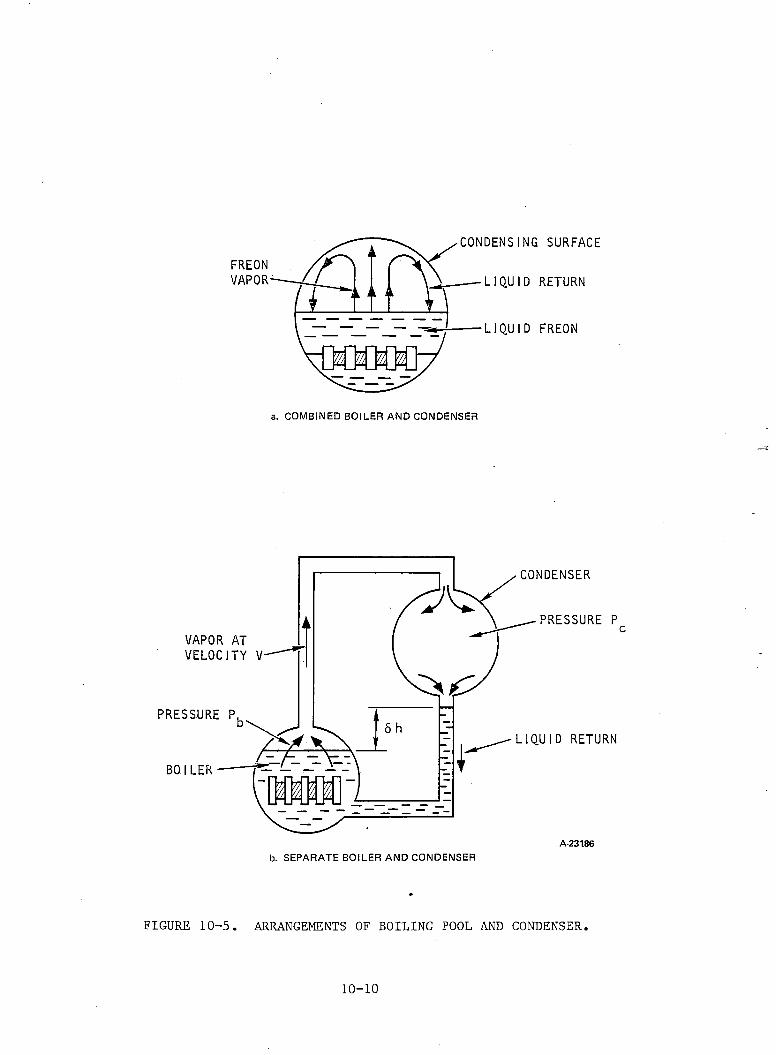
FIGURE 10-5. ARRANGEMENTS OF BOILING POOL AND CONDENSER.
1 0 - 1 0
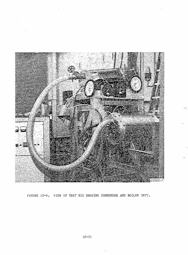
FIGURE 10-6. VIEW OF TEST RIG SHOWING CONDENSER AND BOILER UNIT.
1 0 - 1 1
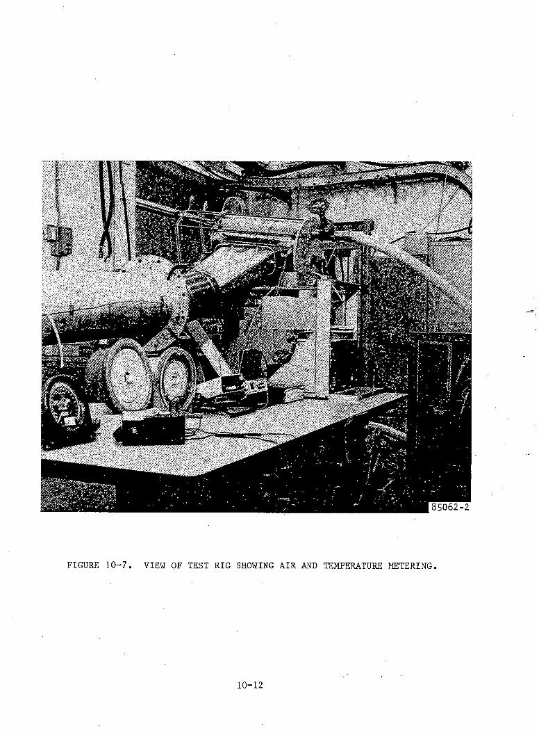
FIGURE 10-7. VIEW OF TEST RIG SHOWING AIR AND TEMPERATURE METERING.
1 0 - 1 2
be measured and the steady-state values to be recorded. The flexible vapor and return pipes enabled various elevation differences to be achieved between the condenser and boiler units (Figure 10-6 shows the boiler in a raised condition). This elevation can be altered by the hydraulic lift shown supporting the boiler unit.
e. Experimental Tests.
(1) Switch-on Transient: One advantage of an immersed two-phase coolingsystem is its relatively long thermal time-constant compared with direct-aircooled systems. To measure the time constant, the heat dissipation in the boiler was switched on and kept constant at 6 kW with the cooling air at900 ft-Vmin and 92.4 °F. Readings of pressures, temperatures, and time were recorded and are shown in Figure 10-8. The thermal time-constant from this graph is 7.9 min.
(2) Effect of Pressure Difference and Elevation Difference: To investigatethe variation of the cooling efficiency of the system with variable separation between boiler and condenser, a series of tests was performed to measure the thermal impedance of the system at a constant boiler pressure of 60 psi and coolant temperature of 160°F. The elevation difference between boiler and condenser was varied, and at each height the control valve used in the Freon- feed pipe was adjusted to produce a set of readings at various pressure differences between condenser and boiler. Figure 10-9 shows the family of dissipation curves normalized at 60 psi to a value of Q/Q0 = 1, corresponding to a dissipation of 8.5 kW in the boiler. The cooling air during this process was 900 ft-Vmin at 104°F. At each point taken, the input dissipation power was adjusted untila steady pressure of 60 psi was obtained in the boiler.
The three curves shown were taken at elevation differences of 42, 24, and 12 in. between boiler and condenser. The top curve shows that as 6P is increased (to simulate either vapor line length increase or pressure drop across the condenser) the dissipating capacity of the system remains virtually constant until <5P = 1.7 psi. At this point, the pressure difference is sufficient for the head of liquid coolant to fill the return pipe with liquid coolant. Any further increase in pressure difference will raise the liquid coolant level in the return pipe until it fills a proportion of the condenser. Since the heat transfer coefficient of vapor condensing on the condenser wall is much greater than that between the liquid coolant and wall, any reduction in the surface area of the condenser wall available to the vapor will lead to an increased thermal impedance of the condenser. This effect is seen for the 42-in. displacement curve above 6P = 1.7 psi, which shows a reduction in dissipation for a given liquid coolant temperature. At lower values of vertical displacement, this effect will occur at lower pressure differences because a lower head of liquid coolant will reach the condenser outlet. The thermal resistance curves corresponding to Figure 10-9 are given in Figure 10-10 based on the log mean temperature difference between boiler liquid coolant temperature and cooling air temperature. These curves show the same effect of coolant transfer from boiler to condenser at a given pressure difference.
10-13

EVAP
ORAT
OR P
RESS
URE
, PS
IA
• POWER INPUT = 6000W• COOLING AIR TEMPERATURE = 92.4°• COOLING AIRFLOW = 900 CFM• CONDENSER TO EVAPORATOR
ELEVATION DIFFERENCE = 42 IN.
30 40 50TIME, min
FIGURE 10-8. EVAPORATOR PRESSURE AS A FUNCTION OF TIME.
F
60
A-23183
10-14
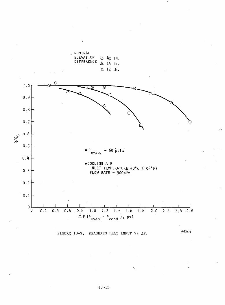
NOMINALELEVATION 0 42 IN DIFFERENCE A ^ ^
□ 12 IN.
A P (p - p ) ps ievap. cond. r
FIGURE 10-9. MEASURED HEAT INPUT VS AP A-23178
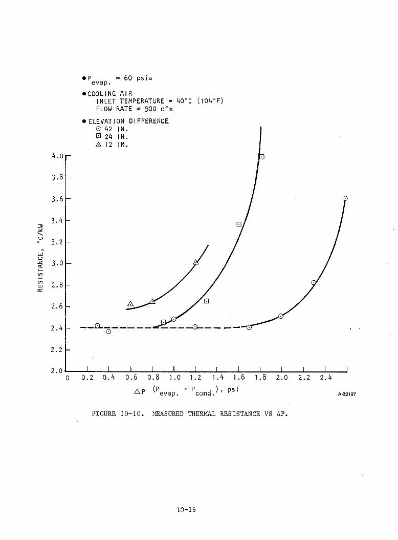
RESI
STAN
CE,
°C/k
W
• P = 60 psiaevap.•COOLING AIR
INLET TEMPERATURE = ^0°C (104°F) FLOW RATE = 900 cfm
• ELEVATION DIFFERENCE
FIGURE 10-10. MEASURED THERMAL RESISTANCE VS AP.
10-16
f. Conclusions. The test results show that the two-phase cooling method of power electronic components can be constructed with separation of the boiling pool and condensing actions into two units connected by.a Freon feed pipe and a return pipe for the condensed liquid coolant. The separation distance can be increased up to the point where the pressure differential between boiler and condenser is either significant compared with the boiler pressure or is large enough to suck liquid coolant up the return pipe into the condenser. The first condition produces a higher boiler liquid coolant temperature as a result of the increase in boiler pressure; the second condition produces a higher coolant temperature as a result of the reduced condenser operating area. During the series of tests, the pressure differential was below 2 psi, which is small (3 percent) when compared with the 60-psi boiler pressure. Up to point where the condenser starts to fill with liquid coolant, therefore, the reduction in heat dissipation is relatively small.The experiment has produced several design criteria for two-phase cooling systems with separated boiling pool and condenser:
(1) If gravity return of liquid coolant is required, a minimum vertical displacement is necessary to avoid the pressure differential producing a liquid coolant level in the condenser.
(2) If the condenser is to be positioned below this minimum, a scavenging pump will be required.
(3) Pipe diameters must be chosen so as to ensure an acceptable pressure differential at the maximum heat dissipation.
(4) The condenser pressure drop must be kept within acceptable limits.
(5) The system must be airtight at the pressures below atmospheric that can occur when the power electronic equipment is not in use at minimum temperature; at the same time it must also be capable of withstanding the operating pressure.
(6) An air trap and/or venting system is probably necessary. The venting system should be capable of detecting the presence of air and to vent the air trap when system pressure is greater than atmospheric.
REFERENCES
1. Rollet, H., "Two-Phase Freon Cooling for Electronic Power Equipment," Proc. International Conference on Advanced Propulsion Systems for Urban Rail Vehicles, 1980, pp. 142-161.
2. Brock, C. ii., and E. C. Coyner, "Freon Dielectric-Coolants," Proc. 6th Electrical Insulation Conference, 1965, pp. 247-250.
10-17
EXHIBIT 10A
TEST PLAN FOR FREON TWO-PHASE COOLING EXPERIMENT
1. Test Plan. A natural circulation Freon cooling method with separate condenser will be used.
(a) Test Setup Schematic (see Figure 10A-1)
(b) Test Apparatus (see Table 10A-1)
(c) Instrumentation (see Table 10A-2)
(d) Test Run Specifications (see Table 10A-3)
2. Test Objective. The objective of the test is to investigate the feasibility of obtaining physical separation between the condenser and evaporator of a Freon- based evaporative cooling system for locomotive applications. This objective can best be accomplished by testing a commercial finned-tube heat exchanger on a subscale level and studying the effect of the physical separation length, elevation difference (between the condenser and evaporator), and flow instability on the performance of the cooling system. Subsequently it was decided that an existing bellows condenser should be used in lieu of a finned-tube heat exchanger and that the test be focused on three basic areas that might affect the cooling system performance:
(a) Physical separation length
(b) Elevation difference between the condenser and evaporator
(c) Freon-side condenser pressure drop
Initially, 40 test runs were planned as specified in Table 10A-3. The test results can be reduced to establish the limitations of the natural circulation Freon cooling concept as a function of condenser pressure drop and the physical proximity of the components. The effect of air in the condenser, an important item, should also be investigated after the completion of the 40 test runs.
1 0 A - 1
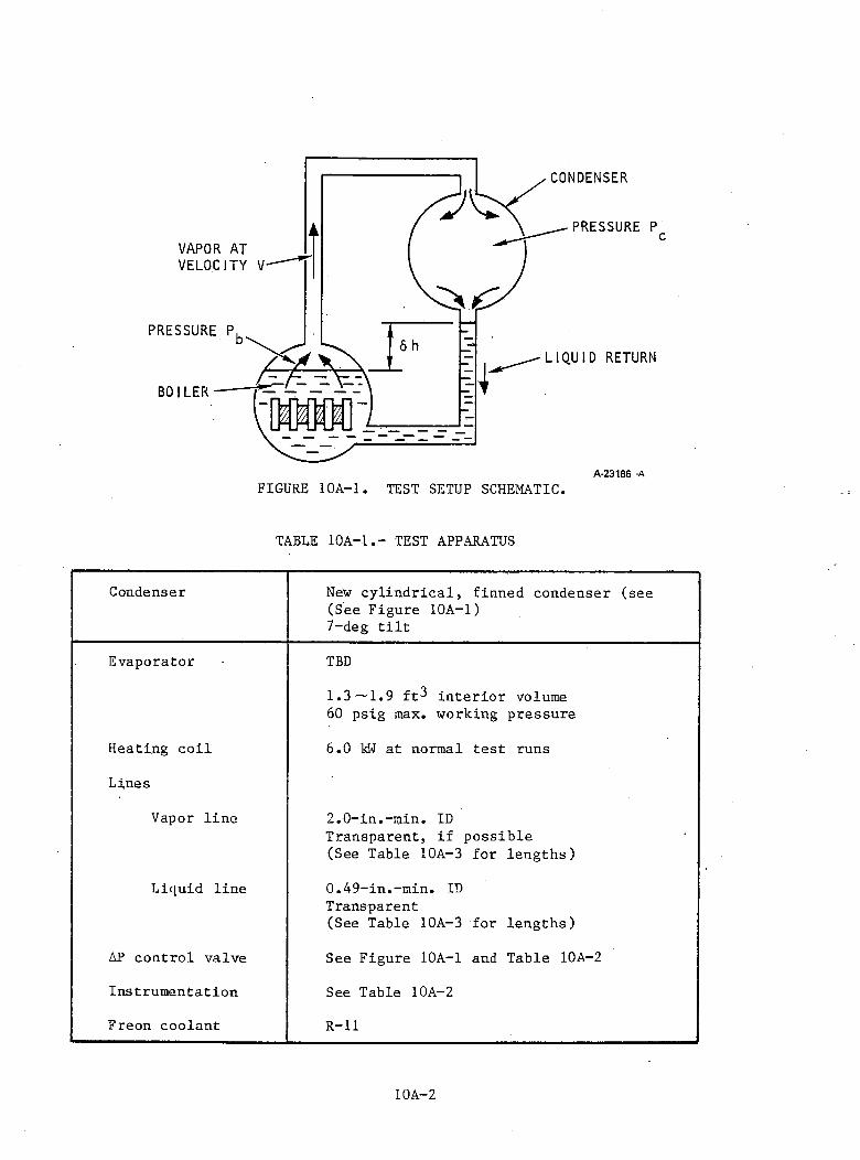
TABLE 10A -1T EST APPARATUS
Condenser New cylindrical, finned condenser (see (See Figure 10A-1)7-deg t i l t
Evaporator TBD
1-3 —1.9 ft^ in terior volume 60 psig max. working pressure
Heating coil 6.0 kW at normal test runs
Lines
Vapor line 2.0-in.-m in. ID Transparent, if possible (See Table 10A-3 for lengths)
Liquid line 0.49-in.-m in. ID Transparent(See Table 10A-3 for lengths)
AP control valve See Figure 10A-1 and Table 10A-2
Instrumentation See Table 10A-2
Freon coolant R-ll
10A-2
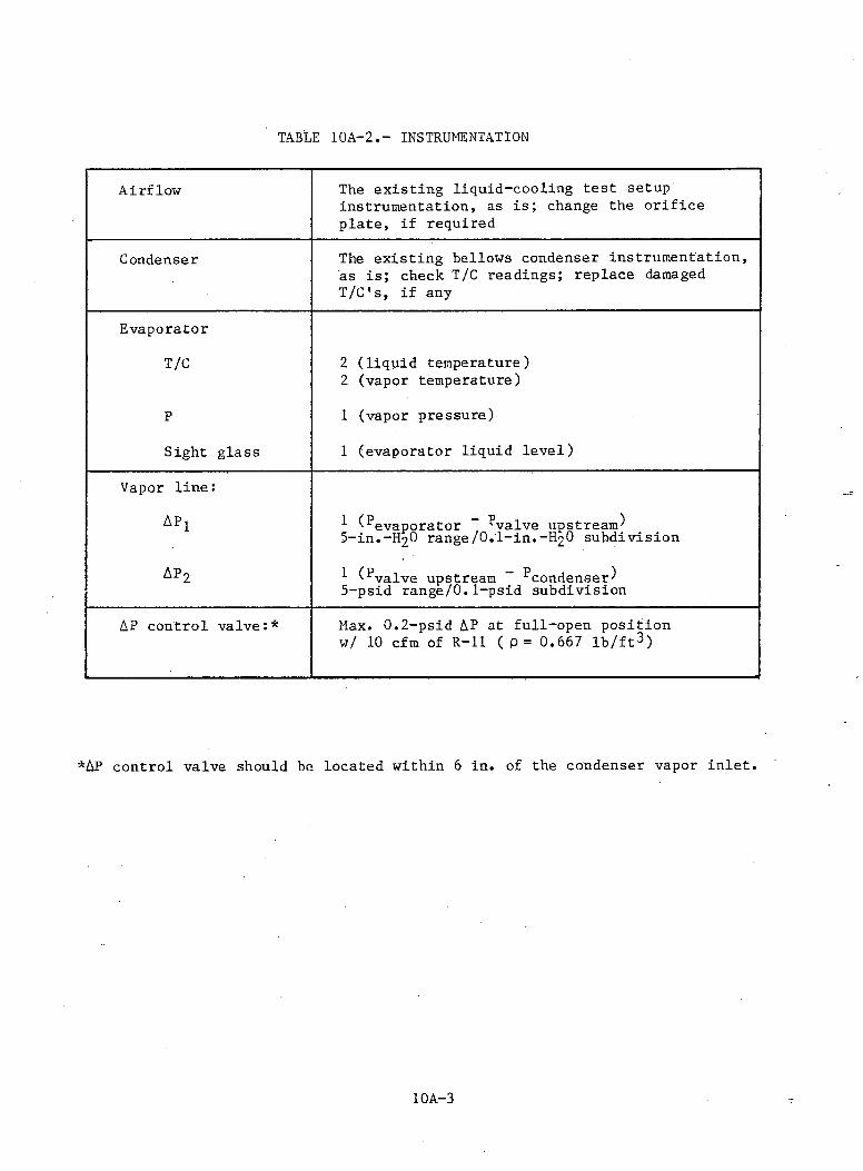
TABLE 10A-2INSTRUMENTATION
Airflow The existing liquid-cooling test setup instrumentation, as is ; change the o rifice plate, if required
Condenser The existing bellows condenser instrumentation, as is ; check T/C readings; replace damaged T/C's, if any
Evaporator
T/C 2 (liquid temperature) 2 (vapor temperature)
P 1 (vapor pressure)
Sight glass 1 (evaporator liquid level)
Vapor line:
APi 1 (^evaporator - ^valve upstream^ 5-in.-H 20 range/0.1-in,-H 20 subdivision
ap2 (^valve upstream - ^condenser) 5-psid range/0.1-psid subdivision
AP control valve:* Max. 0.2-psid AP at full-open position w/ 10 cfm of R -ll ( p = 0.667 lb /ft^ )
*AP control valve should be located within 6 in. of the condenser vapor in le t.
10A-3
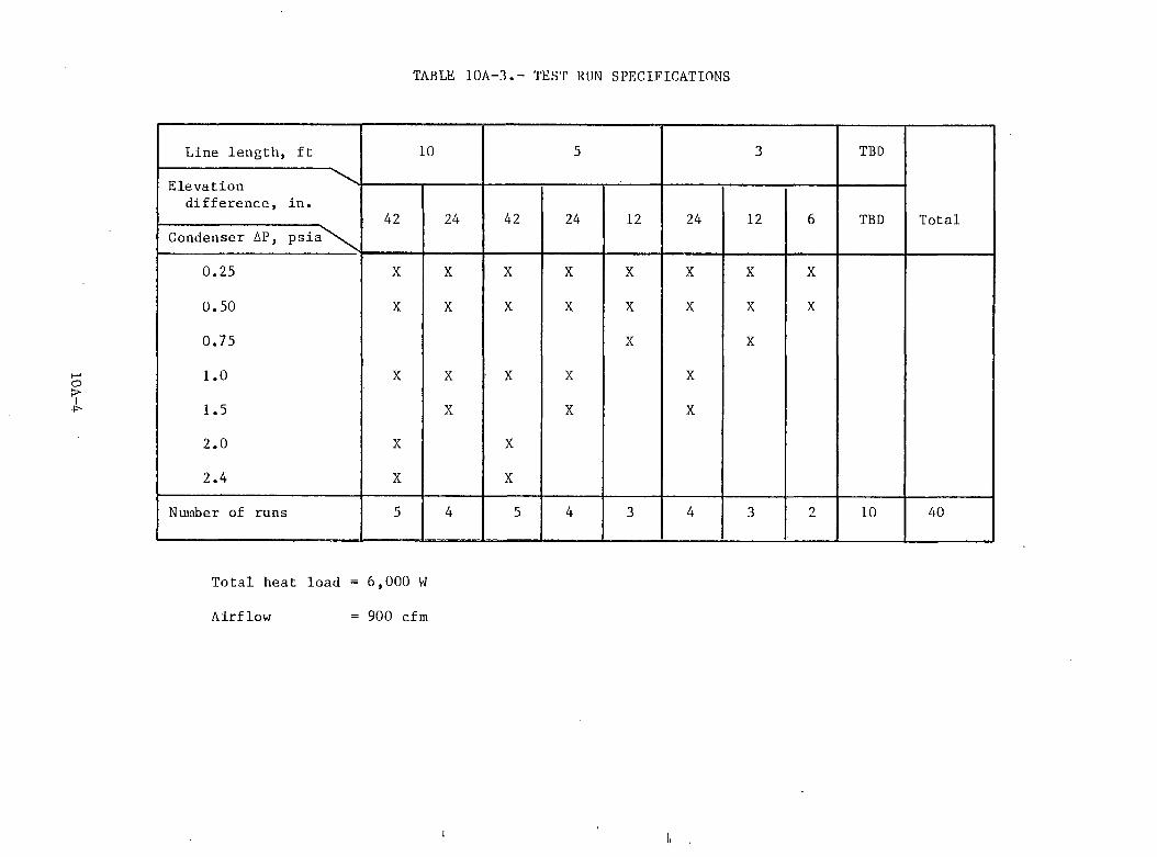
10A-4
TABLE 10A-3.- TEST RUN SPECIFICATIONS
Total heat load = 6,000 W
Airflow - 900 cfm

11. CONCLUSIONSa. Requirements. The previous sections have described in detail the various inverter c ircu its that can be derived from the TLRV PCU hardware. The simple three-phase Graetz type bridge is unlikely to provide an adequate traction performance except in the case of the PWM variants. As stated in Section 5of this report, the requirement for high starting torque combined with low torque pulsation at low frequency differentiates the traction power drive from many of i ts industrial counterparts. Above this starting region, good efficiency and power factor become important considerations in the circu it selection . At the same time, this performance must be achieved at an Overall cost that has to be compared with that of a conventional dc commutator system.
b. Comparison of the Candidate Systems. Table 11-1 shows a comparison of the basic candidate systems along with variants that have been selected to produce an acceptable traction performance. These variants can be divided into the following groups:
(1) Converters using PWM to achieve a three-phase output with low harmonic content
(2) Converters using multiple bridges to produce better output waveforms, or outputs with greater than three phases
(3) Hidden link or direct converters
Groups 2 and 3 include both motor-(or lin e -) commutated converters; Group 1 contains only self-commutated converters. The cost figures given are a normalized comparison of power component costs, excluding control c ircu it costs, packaging, e t c . , but the numbers are expected to provide a re a lis tic approximation to the ratio of final costs. These designs are based on thyristors commercially available at the time of writing, and the variation of current loading and duty cycle between bridges has decided the power component arrangement for each bridge.
The three-phase 6-step line-commutated bridge is the least expensive bridge and has been taken as a reference for a ll the others. I ts performance and cost are summarized in Line 1 of Table 11-1. I t is unlikely that either this bridge or Bridge 2 would be suitable for a traction drive in view of the low efficiency and high torque pulsation.
Bridges 3 and 4 of Table 11-1 are two interesting variants of the doublebridge group. In Type 3 a 12-step waveform is produced by phase-shifting the two parallel 6-step bridges by 30 deg and summing the currents into a three-phase motor. In Type 4, on the other hand, a six-phase motor is supplied from two6-step bridges phase-shifted by 30 deg. As explained in Section 4 the six-phase machine produces no torque pulsation at six times supply frequency. The f ir s t torque harmonic of this system is the twelfth, which has approximately half the magnitude of the three-phase 6-step bridge. The double-bridge 12-pulse system, on the other hand, has a sixth harmonic torque component that is load-dependent and approaches that of the three-phase 6-step bridge at fu ll load. Both bridges produce losses of approximately 50 percent of the three-phase 6-step bridge, but have an increased power component cost of 53 percent.
11-1
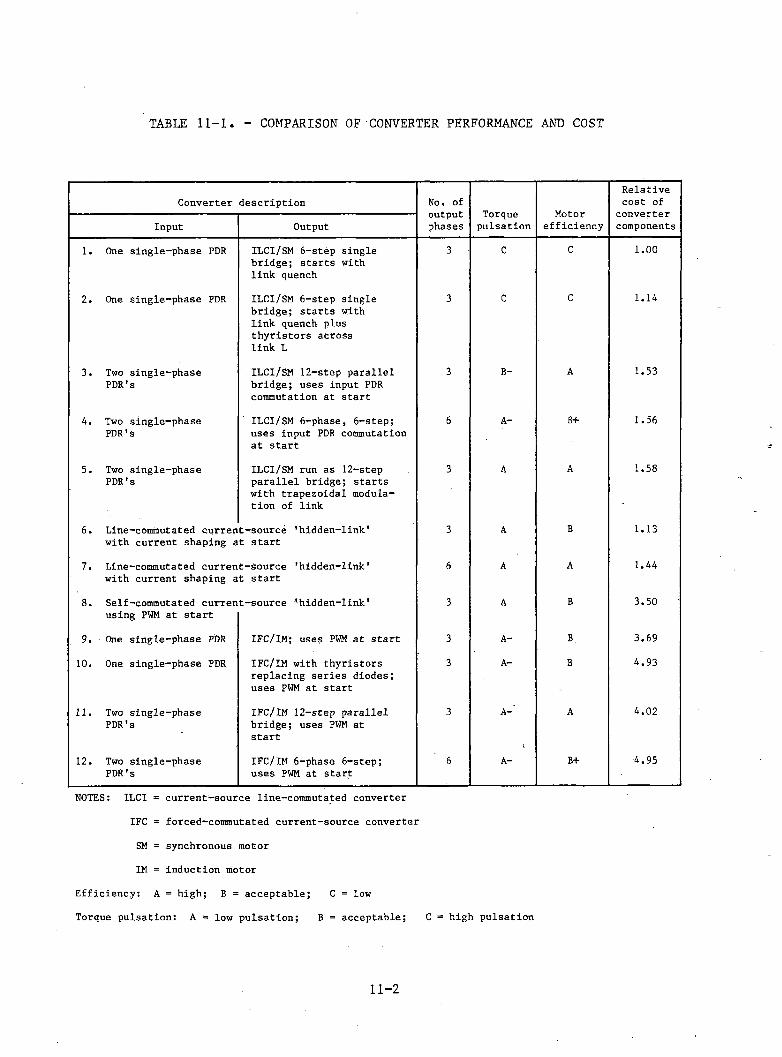
TABLE 11-1. - COMPARISON OF CONVERTER PERFORMANCE AND COST
Converter description No. of output phases Torquepulsation
Relative cost ofInput Output efficiency components
1. One single-phase PDR XLCI/SM 6-step single bridge; starts with link quench3 C c 1.00
2. One single-phase PDR ILCI/SM 6-step single bridge; starts with link quench plus thyristors across link L
3 C c 1.14
3. Two single-phase PDR's ILCI/SM 12-step parallel bridge; uses input PDR commutation at start3 B- A 1.53
4. Two single-phase PDR's ILCI/SM 6-phase, 6-step; uses input PDR commutation at start6 A- B+ 1.56
5. Two single-phase PDR's ILCI/SM run as 12-step parallel bridge; starts with trapezoidal modulation of link
3 A A 1.58
6. Line-commutated curren with current shaping at-source 'hidden-link' t start 3 A B 1.13
7. Line-commutated current-source 'hidden-link' with current shaping at start 6 A A 1.44
8. Self-commutated curren using PWM at start t-source 'hidden-link' 3 A B 3.50
9. One single-phase PDR IFC/IM; uses PWM at start 3 A- B. 3.6910. One single-phase PDR IFC/IM with thyristors replacing series diodes; uses PWM at start
3 A- B 4.93
n. Two single-phase PDR's IFC/IM 12-step parallel bridge; uses PWM at start3 A-
i
A 4.02
12. Two single-phase PDR's IFC/IM 6-phase 6-step; uses PWM at start 6 A- B+ 4.95
NOTES: ILCI = current-source line-commutated converterIFC = forced-commutated current-source converter SM = synchronous motor IM = induction motor
Efficiency: A = high; B = acceptable; C = lowTorque pulsation: A = low pulsation; B = acceptable; C = high pulsation
11-2
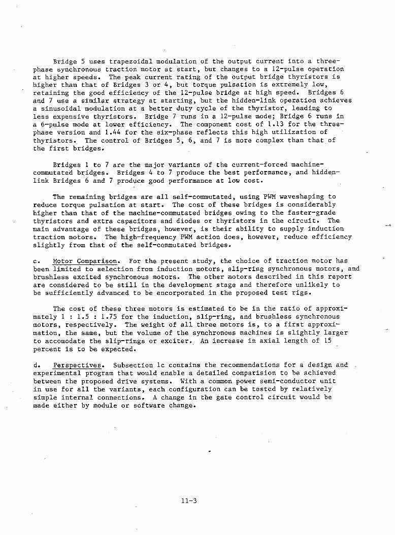
Bridge 5 uses trapezoidal modulation of the output current into a three- phase synchronous traction motor a t s ta r t , but changes to a 12-pulse operation at higher speeds. The peak current rating of the output bridge th yristors is higher than that of Bridges 3 or 4 , but torque pulsation is extremely low, retaining the good efficiency of the 12-pulse bridge at high speed. Bridges 6 and 7 use a similar strategy at startin g , but the hidden-link operation achieves a sinusoidal modulation at a better duty cycle of the th y risto r, leading to less expensive th y risto rs. Bridge 7 runs in a 12-pulse mode; Bridge 6 runs in a 6-pulse mode a t lower efficiency. The component cost of 1.13 for the three- phase version and 1.44 for the six-phase reflects th is high u tiliza tio n of th yristo rs. The control of Bridges 5, 6, and 7 is more complex than that of the f i r s t bridges.
Bridges 1 to 7 are the major variants of the current-forced machine- commutated bridges. Bridges 4 to 7 produce the best performance, and hidden- link Bridges 6 and 7 produce good performance at low co st.
The remaining bridges are a l l self-commutated, using PWM waveshaping to reduce torque pulsation at s ta r t . The cost of these bridges is considerably higher than that of the machine-commutated bridges owing to the faster-grade th yristors and extra capacitors and diodes or thyristors in the c ir c u it . The main advantage of these bridges, however, is their ab ility to supply induction traction motors; The high-frequency PWM action does, however, reduce efficiency slig h tly from that of the self-commutated bridges.
c . Motor Comparison. For the present study, the choice of traction motor has been limited to selection from induction motors, slip -ring synchronous motors, and brushless excited synchronous motors. The other motors described in this report are considered to be s t i l l in the development stage and therefore unlikely tobe su fficien tly advanced to be encorporated in the proposed te s t r ig s .
The cost of these three motors is estimated to be in the ra tio of approximately 1 : 1.5 : 1.75 for the induction, slip -ring, and brushless synchronous motors, respectively . The weight of a l l three motors i s , to a f i r s t approximation, the same, but the volume of the synchronous machines is slig h tly larger to accomodate the slip -rings or e x c ite r . An increase in axia l length of 15 percent is to be expected.
d. Perspectives. Subsection lc contains the recommendations for a design and experimental program that would enable a detailed comparision to be achieved between the proposed drive systems. With a common power semi-conductor unitin use for a l l the variants, each configuration can be tested by relativ ely simple internal connections. A change in the gate control c ircu it would be made either by module or software change.
11-3

APPENDIXES

APPENDIX A
TECHNICAL FEATURES AND CHARACTERISTICS OF EXISTING AC PROPULSION SYSTEM
Figure A-l is a block diagram of the power c ircu it and associated controls for the existing linear induction motor (LIM) ac propulsion system. In the drive mode, 60-Hz wayside power is applied to the input of the phase-delay re c tifie r from which the variable dc output, f ilte red by the inductor, is applied to the in verter. The variablevoltage, variable-frequency inverter output is connected to the LIM and the synchronous capacitor. The la tte r provides power-factor correction for the LIM, and maintains an ac voltage necessary for the line commutation of the inverter.
In the braking mode, the kinetic energy of the moving vehicle is converted into e le c tr ica l energy by the LIM and is returned to the wayside power system through the onboard power conversion equipment. This reverse power flow is achieved without power contactors simply by reversing the functions of the two converters, i . e . , by changing their thyristor firing angle.
The ac propulsion system requirements include: (a) operation from 8250-V,three-phase, 60-Hz wayside power; (b) capability to provide 22,220 N thrust at a cruise speed of 480 km/h; (c) provision for regenerative braking; and (d) smooth control of thrust with jerk limiting over the entire speed range.
The main feature of the propulsion system is i ts high power-to-weight ra tio , which is a basic requirement for levitated , high-speed vehicles such as the TLRV. The overall system power density is less than 1.5 kg/kW, which is the result of the liquid cooling of a ll power components. This includes hollow-conductor direct liquid cooling of the LIM, synchronous capacitor, inducto r, and auxiliary power transformer; and liquid-cooled heat sinks for the power thyristors. The selected coolant is deionized water. Major component sp ecifications are presented in Table A -l.
Primary control of the propulsion system is established by the tractive effort command. In this application, dc link current is approximately proportional to the tractiv e e ffo rt; thus, the positive dc current command represents a request for positive acceleration (drive mode); a negative command represents a request for deceleration (brake mode). This command determines only acceleration not vehicle direction. The rate of acceleration or deceleration ordered is limited by the jerk control.
Another input command is produced by the speed lim it control that establishes a maximum e le c tr ic a l frequency for the system. Propulsion effort at any frequency below this setting is determined by the thrust control only.When the selected maximum frequency is approached, the accelerating thrust is automatically reduced so that the selected frequency limit is not exceeded.
A third input command selects the phase rotation of the three-phase inverter output according to the direction of travel desired. This control is effective only when the vehicle is at rest.
A-l
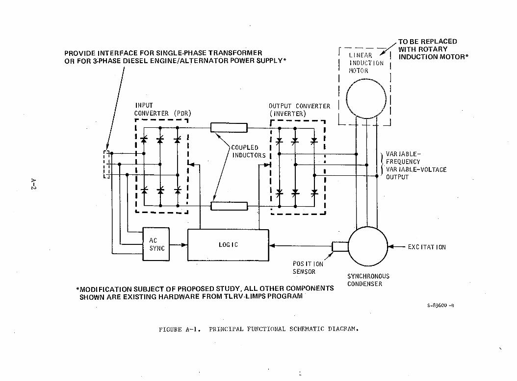
A-2
SHOWN ARE EXISTING HARDWARE FROM TLRV-LIMPS PROGRAMS -8 9 6 0 0 -B
FIGURE A -l. PRINCIPAL FUNCTIONAL SCDF.MATIC DIAGRAM.
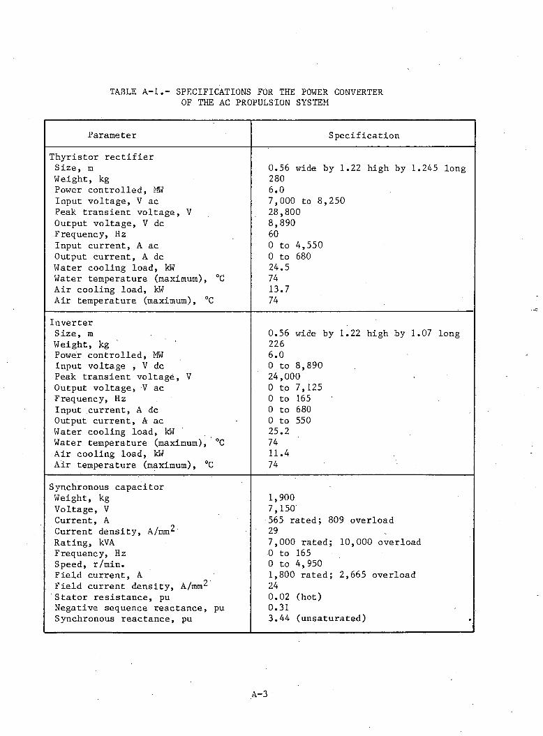
TABLE A-lSPECIFICATIONS FOR THE POWER CONVERTER OF THE AC PROPULSION SYSTEM
Parameter Specification
Thyristor re c t if ie rSize, m 0.56 wide by 1.22 high by 1.245 longWeight, kg 280Power controlled, MW 6.0Input voltage, V ac 7,000 to 8,250Peak transient voltage, V 28,800Output voltage, V dc 8,890Frequency, Hz 60Input current, A ac 0 to 4,550Output current, A dc 0 to 680Water cooling load, kW 24.5Water temperature (maximum), °C 74Air cooling load, kW 13.7Air temperature (maximum), °C 74
InverterSize, m 0.56 wide by 1.22 high by 1.07 longWeight, kg 226Power controlled, MW 6.0Input voltage , V dc 0 to 8,890Peak transient voltage, V 24,000Output voltage, V ac 0 to 7,125Frequency, Hz 0 to 165Input current, A dc 0 to 680Output current, A ac 0 to 550Water cooling load, kW 25.2Water temperature (maximum), °C 74Air cooling load, kW 11.4Air temperature (maximum), °C 74
Synchronous capacitorWeight, kg 1,900Voltage, V 7,150Current, A 565 rated; 809 overloadCurrent density, A/mm 29Rating, kVA 7,000 rated; 10,000 overloadFrequency, Hz 0 to 165Speed, r/min. 0 to 4,950Field current, A 1,800 rated; 2,665 overloadField current density, A/mm 24Stator resistance, pu 0.02 (hot)Negative sequence reactance, pu 0.31Synchronous reactance, pu 3.44 (unsaturated)
A-3
The field current delivered to the synchronous capacitor is automatically controlled in response to inputs from the dc link current command.
Because the inverter cannot be line commutated from the synchronous capacito r until su fficien t back-emf is available, a special s ta r t mode is necessary to bring the synchronous machine- up to a minimum operating speed. This is accomplished by selectively pulsing sets of machine winding through the in verter, which causes the machine to accelerate until a speed is reached at which the generated voltage w ill permit line commutation. During the s ta r t mode, inverter commutation is achieved through current quenching by the phase-delay r e c t i f ie r . This s ta rt operation is accomplished automatically by special logic and shaft position/speed sensors.
A-4
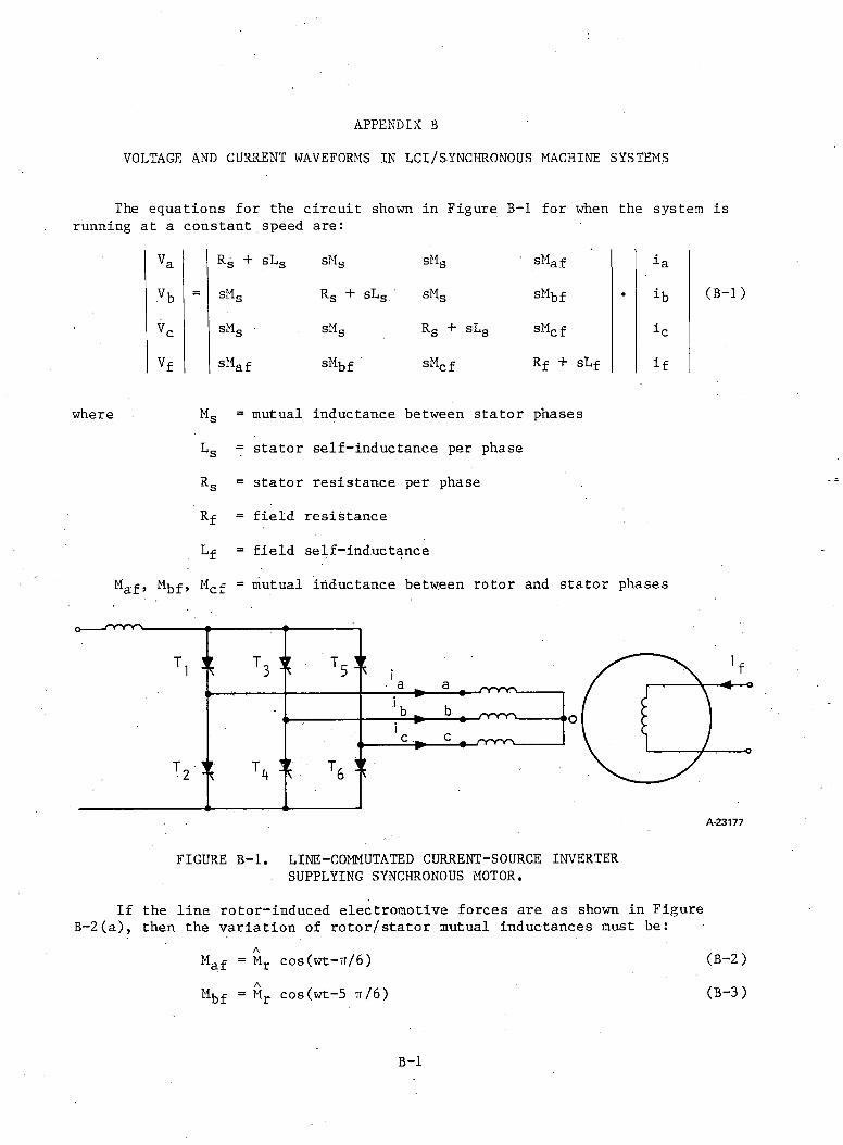
APPENDIX B
VOLTAGE AND CURRENT WAVEFORMS IN LCI/SYNCHRONOUS MACHINE SYSTEMS
The equations for the circu it shown in Figure B-l for when the system is running at a constant speed are:
where
Va Rg + SLg SMg SMg sMaf ia
vb = sMs Rg + SLg SMg sMbf • ib
Vc SMg SMg Rs + sLs sMcf
Vf sMaf sMbf sMcf Rf + sLf if
Ms = mutual inductance between stator phases
RsRf
stator self-inductance per phase
stator resistance per phase
field resistance
field self-inductance
(B -l)
Maf , M f, Mc f = mutual inductance between rotor and stator phases
FIGURE B -l. LINE-COMMUTATED CURRENT-SOURCE INVERTER SUPPLYING SYNCHRONOUS MOTOR.
If the line rotor-induced electromotive forces are as shown in Figure B -2(a), then the variation of ro to r/sta to r mutual inductances must be:
M a f = M t c o s ( w t - T r / 6 )
M j j - f - M r c o s ( w t - 5 i t / 6 )
(B-2 ) ( B - 3 )
B-l
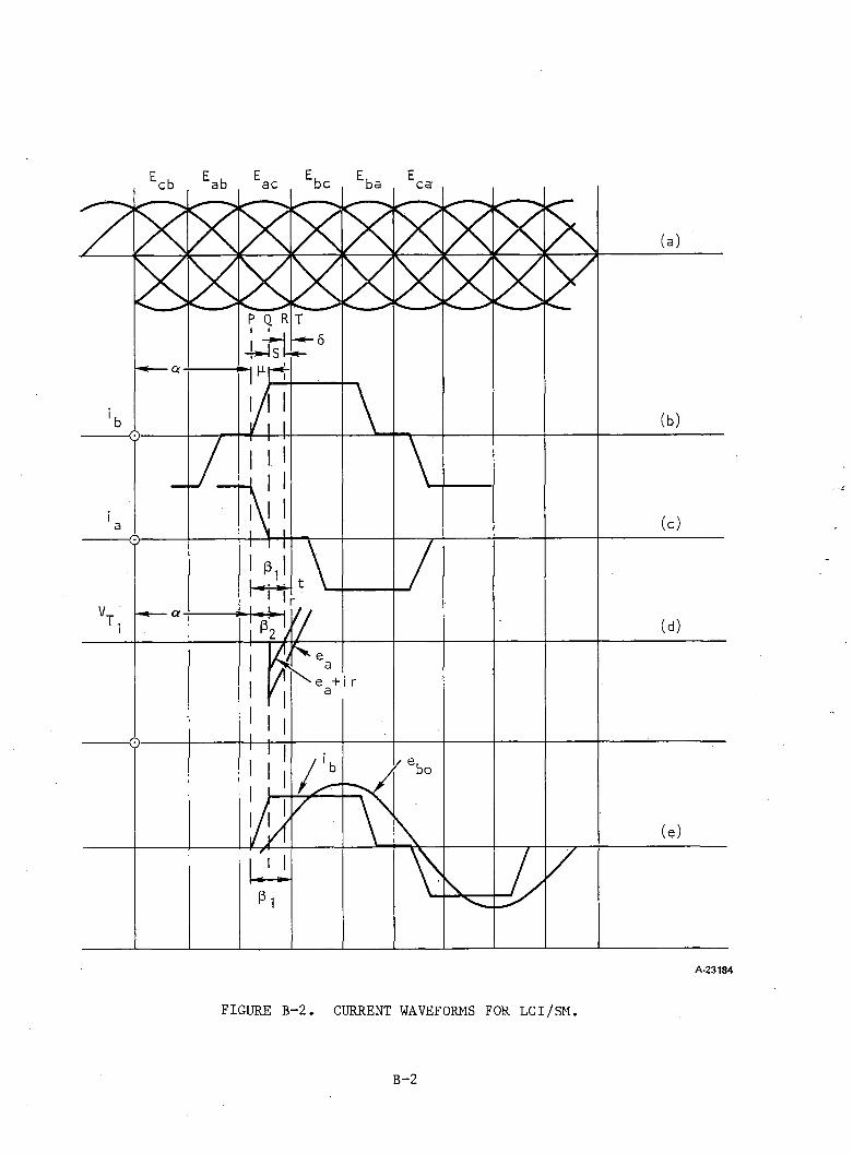
FIGURE B-2. CURRENT WAVEFORMS FOR LCI/SM.
B-2
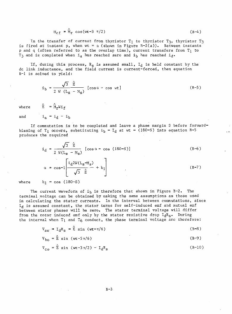
(B-4)AHcf = Mr cos(wt-3 tt/2 )
In the transfer of current from thyristor to thyristor T3 , thyristor T3 is fired at instant p, when wt = a (shown in Figure B-2(a)). Between instants p and q (often referred to as the overlap time), current transfers from T]_ to T3 and is completed when ia has reached zero and ig has reached i^.
If, during this process, Rs is assumed small, 1^ is held constant by the dc link inductance, and the field current is current-forced, then equation B-l is solved to yield:
ib - [coset COS2 W (Ls - Mg)
A Awhere E = MrWif
and -*-a = id “ ib
(B-5)
If commutation is to be completed and leave a phase margin S before forwardbiasing of Tj occurs, substituting ig = 1^ at wt = (180-S) into equation B-5 produces the required
i-dy r e
2 W(Ls - M s)
^ W a g - M s )
[cosa - cos (180-S)]
a = cos- 1
where ki =
y j e
cos (180-S)
+ ki
(B-6 )
(B-7)
The current waveform of i^ is therefore that shown in Figure B-2. The terminal voltage can be obtained by making the same assumptions as those used in calculating the stator currents. In the interval between commutations, since Ij is assumed constant, the stator terms for self-induced emf and mutual emf between stator phases will be zero. The stator terminal voltage will differ from the rotor induced emf only by the stator resistive drop I B-s* During the interval when T^ and Tg conduct, the phase terminal voltage are therefore:
Vao = I^Rg = E sin (wt-r/6 ) (B-8 )
V^Q = E sin (wt-5-rr/6) (B-9)
Vco = E sin (wt-3ir/2) - I^RS (B-10)
B - 3
The bias across each thyristor can be calculated at the end of the overlap period. During commutation from T3 and T3 , Vco will remain unaltered if I<j is constant. Since dia/dt = “di^/dt, the mutual electromotive forces induced in phase c by ia and i^ will cancel. When T3 and T3 are conducting simultaneously, the terminal voltage of phases a and b are the same if the thyristor voltage drop is neglected. The terminal voltage during this overlap is given by:
eao + ebo + IdRsVto = ---------------- (B 11 )
2
where vto = voltage of top dc rail relative to neutral
and e = instantaneous rotor induced emf
B-4
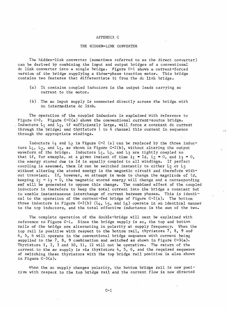
APPENDIX CTHE HIDDEN-LINK CONVERTER
The hidden-link converter (sometimes referred to as the direct converter) can be derived by combining the input and output bridges of a conventional dc link converter into a single bridge. Figure C-l shows a current-forced version of the bridge supplying a three-phase traction motor. This bridge contains two features that differentiate it from the dc link bridge.
(a) It contains coupled inductors in the output leads carrying ac current to the motor.
(b) The ac input supply is connected directly across the bridge with no intermediate dc link.
The operation of the coupled inductors is explained with reference to Figure C-2. Figure C-2(a) shows the conventional current-source bridge. Inductors Lj and L2 , if sufficiently large, will force a constant dc current through the bridge; and thyristors 1 to 6 channel this current in sequence through the appropriate windings.
Inductors L 3 and L2 in Figure C-2 (a) can be replaced by the three inductors L 3 , L2 , and L3 , as shown in Figure C-2(b), without altering the output waveform of the bridge. Inductors L^, L2 , and L3 are tightly coupled so that if, for example, at a given instant of time i^ = Id, i2 = 0, and i3 =0, the energy stored due to Id is equally coupled to all windings. If perfect coupling is assumed, then Id can be switched instantly to either L2 or L3 without altering the stored energy in the magnetic circuit and therefore without transient. If, however, an attempt is made to change the magnitude of Id, keeping i2 = 1 3 = 0 , the magnetic stored energy will change and a corresponding emf will be generated to oppose this change. The combined effect of the coupled inductors is therefore to keep the total current into the bridge a constant but to enable instantaneous interchange of current between phases. This is identical to the operation of the current-^fed bridge of Figure C-2(a). The bottom three inductors in Figure C-2(b) (L4 , L5 , and Lg) operate in an identical manner to the top inductors, and the total effective inductance is the sum of the two.
The complete operation of the double-bridge will next be explained with reference to Figure C-l. Since the bridge supply is ac, the top and bottom rails of the bridge are alternating in polarity at supply frequency. When the top rail is positive with respect to the bottom rail, thyristors 7, 8 , 9 and 4, 5, 6 will operate in the conventional bridge sequence with current being supplied to the 7, 8 , 9 combination and switched as shown in Figure C-3(a). Thyristors 1, 2, 3 and 10, 11, 12 will not be operative. The return of the current to the ac supply is via thyristors 4, 5, 6 , and the required sequence of switching these thyristors with the top bridge rail positive is also shown in Figure C-3(a).
When the ac supply changes polarity, the bottom bridge rail is now positive with respect to the top bridge rail and the current flow is now directed
C-l
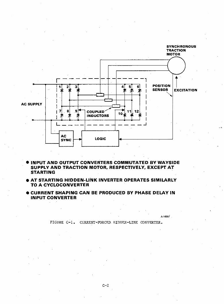
SYNCHRONOUSTRACTIONMOTOR
• INPUT AND OUTPUT CONVERTERS COMMUTATED BY WAYSIDE SUPPLY AND TRACTION MOTOR, RESPECTIVELY, EXCEPT AT STARTING
• AT STARTING HIDDEN-LINK INVERTER OPERATES SIMILARLY TO A CYCLOCONVERTER
• CURRENT SHAPING CAN BE PRODUCED BY PHASE DELAY IN INPUT CONVERTER
A -1 4 5 9 7
FIGURE C-l. CURRENT-FORCED.HIDDEN-LINK CONVERTER.
C - 2
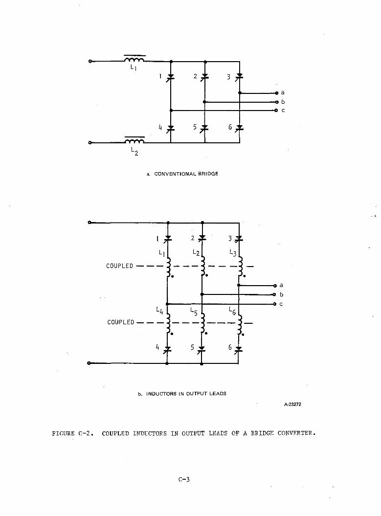
a. CONVENTIONAL BRIDGE
b. INDUCTORS IN OUTPUT LEADS
A-23272
FIGURE C-2. COUPLED INDUCTORS IN OUTPUT LEADS OF A BRIDGE CONVERTER.
C-3
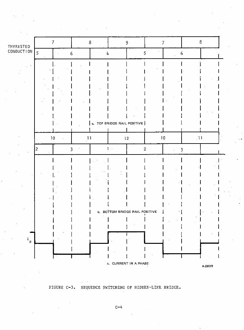
7 8 9 7 8THYRISTEDCONDUCTION
10
a. TOP BRIDGE R A IL POSITIVE
1 1 12 10
b. BOTTOM BRID
I I
I I
GE R AIL POSITIVEII
1 1
c. CURRENT IN A PHASEA-23273
FIGURE C-3. SEQUENCE SWITCHING OF HIDDEN-LINK BRIDGE.
C-4

through thyristors 1,2,3 and 10, 11, 12. The current now flows into the 10,11, 12 combination and out of the 1, 2, 3 combination of thyristors. The switching sequence is as shown in Figure C-3(b). Since the current is assumed to be forced into the motor by the inductors, the current in the a phase will be as shown in Figure C-3(c).
At starting with the output frequency much lower than the supply frequency, the alternation between the (a) and (b) sequence will occur at a fast rate compared with the sequence switching between phases, and commutation of the bridge can therefore be achieved by the supply voltage. A slight error in this timing will occur due to the delay in commutation that is required until the supply voltage reverses.
At higher output frequencies thyristor commutation is produced by both the synchronous motor and the supply. The supply will continue to commutate the bridge between the (a) and (b) sequence in Figure C-3, and the synchronous motor will commutate the thyristors within each sequence group to channel the current into the appropriate phases.
Capacitor-assisted forms of this bridge such as those shown in Figure C-4 are also possible and allow for PWM operation. This bridge is shown with an alternative arrangement of the coupled inductor. Switching from one halfbridge to another when the supply polarity reverses produces a transfer of current from one winding of the inductor to the other with no change in stored energy. The total current into the bridge is, however, forced to be constant by the coupled inductor.
The capacitor and diodes at the input of this bridge are used to improve the input power factor.
C-5
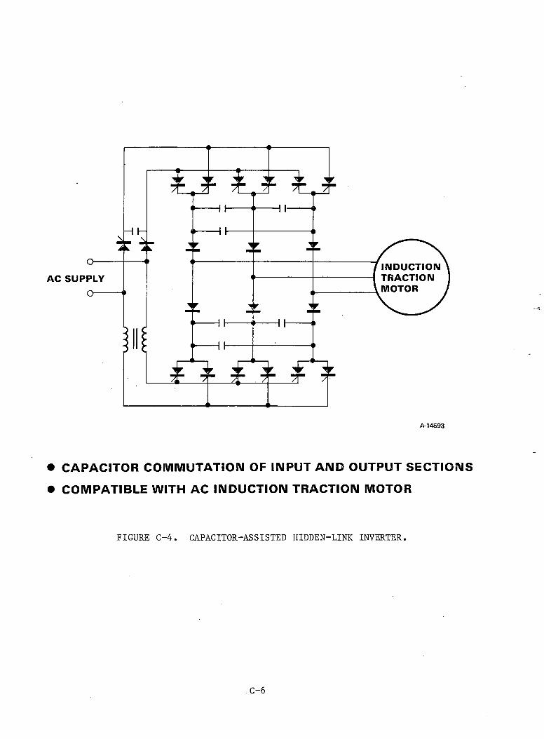
• CAPACITOR COMMUTATION OF INPUT AND OUTPUT SECTIONS• COMPATIBLE WITH AC INDUCTION TRACTION MOTOR
FIGURE C-4. CAPACITOR-ASSISTED HIDDEN-LINK INVERTER.
C-6
APPENDIX DCAPACITOR-ASSISTED CURRENT-SOURCE INVERTER WITH SERIES BLOCKING DIODES SUPPLYING AN ASYNCHRONOUS
TRACTION MOTOR
Figure D-l shows the steps in commutation from one phase to another. Initially Id flows through Th , D4, D5, and H 15. Capacitors C2 and C4 are charged as shown in Figure D-l (a). To transfer conduction from Th4 to Thg, Th is fired and this then applies the charged C4 across TI14. If C4 is sufficiently large, then TI14 will be reverse-biased until it gains its blocking state and Cg will be charged to supply voltage for the next transfer from phase 2 to phase 3.
D-l
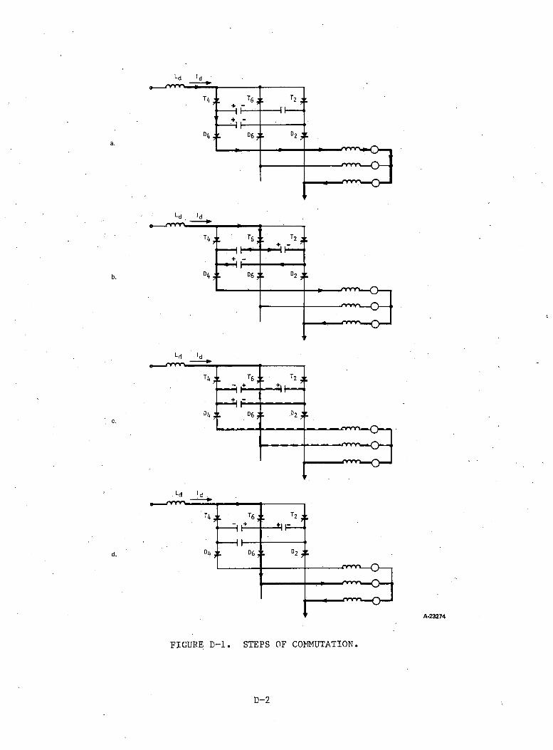
c.
d.
*-d I d
A-23274
FIGURE D-l. STEPS OF COMMUTATION.
D-2
APPENDIX ECAPACITOR-ASSISTED CURRENT-SOURCE INVERTER SUPPLYING AN ASYNCHRONOUS TRACTION MOTOR WITH THE COMMUTATING CAPACITOR
IN THE NEUTRAL CIRCUIT
Figure E-l shows the steps in commutation between phase 3 and phase 1 and between thyristor 2 and thyristor 4. The current and voltage waveforms are shown in Figure E-2.
The process is started by firing the auxiliary thyristor Tn at Tj. Capacitor C was charged as shown in Figure E-l by the last commutation period; therefore a reverse bias is applied to and current is momentarily transferred to C. As C is charged up, T becomes forward-biased and the current path is now transferred to phase 2. During this process, the current into the machine is held constant by the dc link inductance. The capacitor voltage reverses during the commutation and is therefore of the correct polarity to achieve the next commutation from phase 2 to phase 3.
E-l
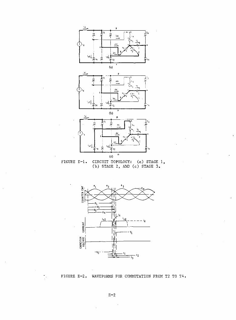
(a)
(b)
FIGURE E -l . CIRCUIT TOPOLOGY: (a) STAGE 1,(b) STAGE 2, AND (c) STAGE 3.
FIGURE E-2. WAVEFORMS FOR COMMUTATION FROM T2 TO T4.
E-2
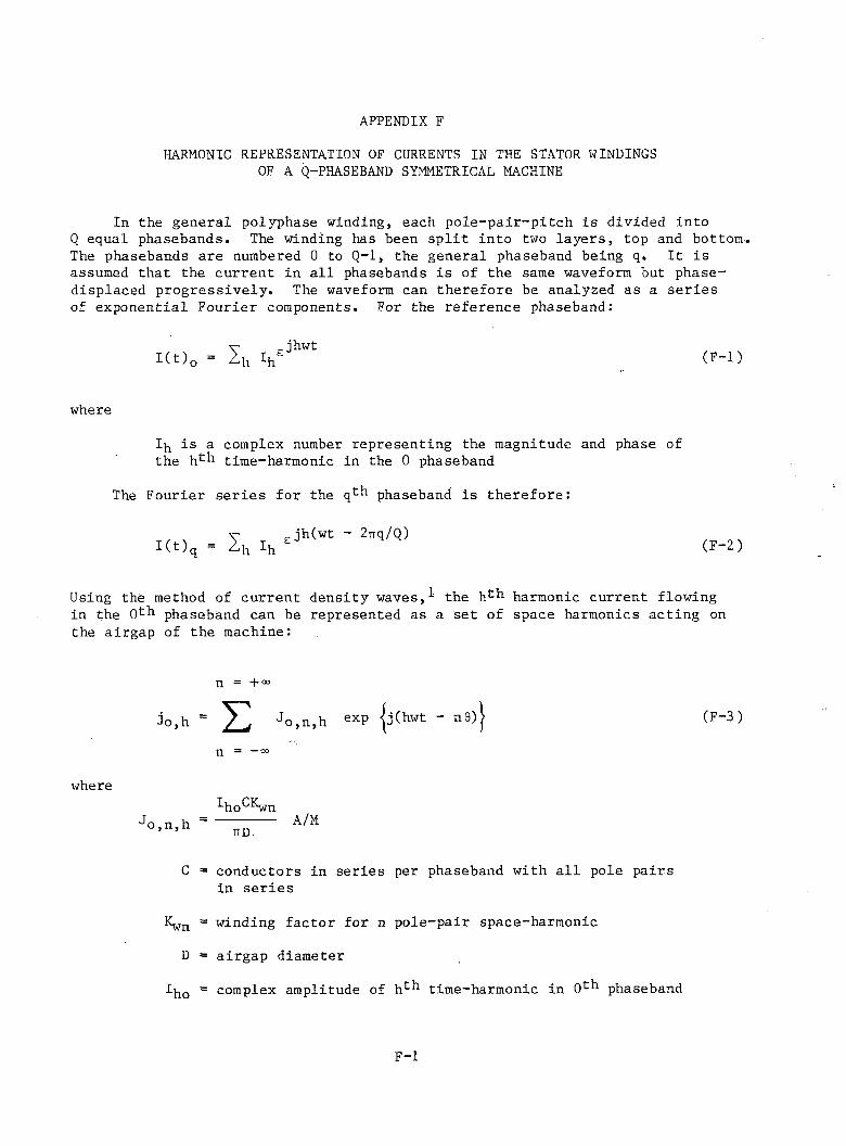
APPENDIX FHARMONIC REPRESENTATION OF CURRENTS IN THE STATOR WINDINGS
OF A Q-PHASEBAND SYMMETRICAL MACHINE
In the general polyphase winding, each pole-pair-pitch is divided into Q equal phasebands. The winding has been sp lit into two layers, top and bottom. The phasebands are numbered 0 to Q-l, the general phaseband being q. I t is assumed that the current in a ll phasebands is of the same waveform but phase- displaced progressively. The waveform can therefore be analyzed as a series of exponential Fourier components. For the reference phaseband:
(F -l)
where
1 is a complex number representing the magnitude and phase of the h^h time-harmonic in the 0 phaseband
The Fourier series for the qth phaseband is therefore:
(F-2)
Using the method of current density waves,^ the hch harmonic current flowing in the O h phaseband can be represented as a set of space harmonics acting on the airgap of the machine:
n = + "
(F-3)
n — CO
where■*-ho wn
A/M
C = conductors in series per phaseband with a ll pole pairs in series
Kwn = winding factor for n pole-pair space-harmonic
D = airgap diameter
I^q = complex amplitude of h1- * 1 time-harmonic in O' - ' 1 phaseband
F-l
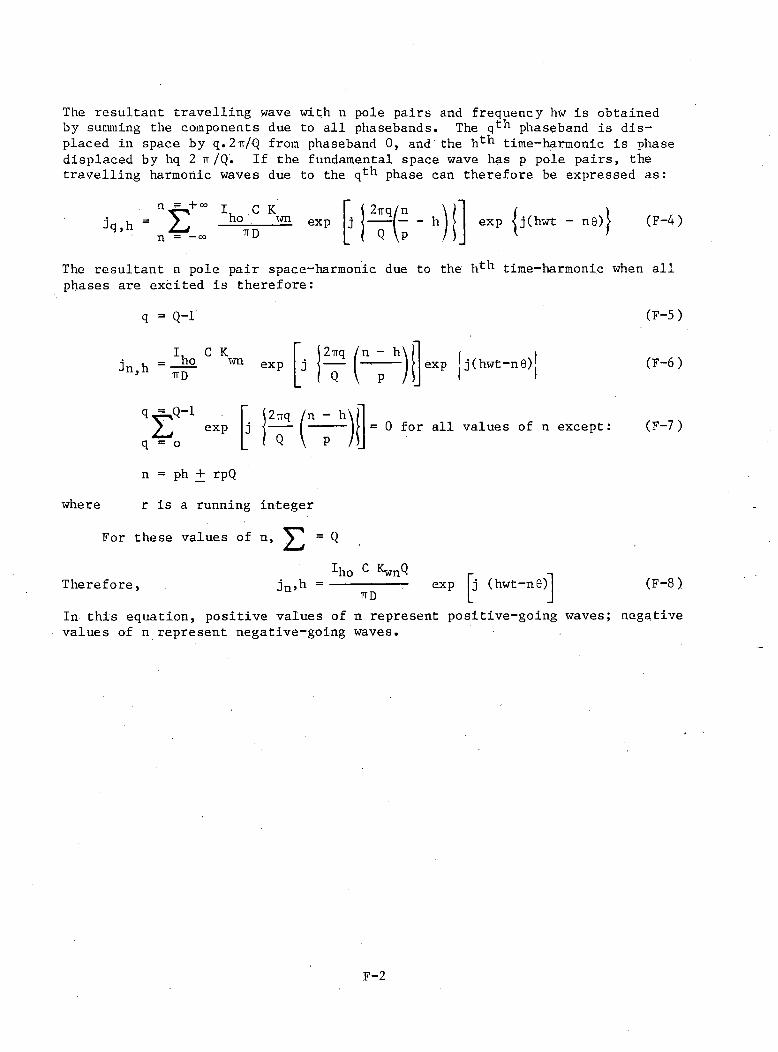
The resultant travelling wave with n pole pairs and frequency hw is obtained by summing the components due to a ll phasebands. The phaseband is displaced in space by q . 2 Tr/Q from phaseband 0 , and the ht ^1 time-harmonic is phase displaced by hq 2 tt/Q. If the fundamental space wave has p pole pairs, the travelling harmonic waves due to the qth phase can therefore be expressed as:
jq,hn£n = —
I, C K ho wnTTD
exp2 -irq/n
Q \ph (F-4)
The resultant n pole pair space-harmonic due to the h11* 1 time-harmonic when a ll phases are, excited is therefore:
q = Q - r
I u G KJn,h exP
1 2 -rrq /n - hexp j(hwt-n 0 )
q ^ Q - 12 ^ expq = o
2 uq /n - h= 0 for a ll values of n except:
n = ph + rpQ
where r is a running integer
For these values of n, ^ ' = Q
pho *“• KwnQTherefore, dn»h
TTDexp j (hwt-n0 )
In this equation, positive values of n represent positive-going waves; values of n represent negative-going waves.
(F-5)
(F-6 )
(F-7 )
(F -8 )
negative
F-2

REFERENCES
Eastham, McLean, "Single-Phase Two-Speed Pole-Change Windings Using Phase-Mixing Techniques," Proc. I .E .E ., Vol. 112, No. 6 , 1965, pp. 1159 1172.
F-3
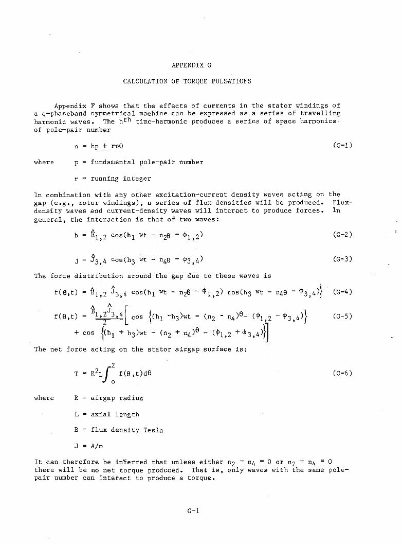
APPENDIX GCALCULATION OF TORQUE PULSATIONS
Appendix F shows that the effects of currents in the s ta to r windings of a q-phaseband symmetrical machine can be expressed as a series of travelling harmonic waves. The hfc time-harmonic produces a series of space harmonics of pole-pair number
n = hp + rpQ (G-l)
where p = fundamental pole-pair number
r = running integer
In combination with any other excitation-current density waves acting on the gap ( e .g . , rotor windings), a series of flux densities w ill be produced. Flux- density waves and current-density waves w ill in teract to produce forces. In general, the interaction is that of two waves:
b = cosCh wt - n20 - ^1,2^ (G-2)
j = c0s(h3 wt - n40 “ $ 3 , 4 )
The force distribution around the gap due to these waves is
f ( 9 , t ) = $ 1 , 2 J 3 ,4 Cos(hi wt ~ n2 0 “ ^1,2^ cos(h3 wt - n4 0 - $ 5 4 )!A,J„
f ( 0 , t ) = 1 >2 3 » 42 cos | ( h i ~h3)wt - (n 2 ~ i ^ ) 6- ($ 1)2 _ t ^ 3 , 4 ^
+ cos |(h-^ + h3 )wt - (n 2 + n4 )® - ( ^ 1 ,2 + ^3 , 4^ }
The net force acting on the stator airgap surface is :
(G-3 )
(G-4)
(G—5)
where
T
R
L
B
J
r2R2L / f (0 ,t)d0J o
airgap radius
axial length
flux density Tesla
A/m
(G—6 )
I t can therefore be inferred that unless either n2 - 1 1 4 = 0 or n2 + n4 = 0 there w ill be no net torque produced. That i s , only waves with the same pole- pair number can in teract to produce a torque.
G-l
If the pole-pair number is of same sign, n2 ~ n^ - 0
T =R 2
L _ 2 . 2TTC0S j c h j - I 1 3 ) w t - (4> 1 , 2 - ^ 3 , 4 ^ } (C-7)
A R B J 3 cos j(h^ “ h3 ) wt - (6 1 , 2 — *^3,4^= — 7
where A = 2ttR = surface area of airgap
If the pole-pair number is of opposite sign, **2 n4 = 0
Ar£,J, ( s .)T =-----^ 1 cos |(h + I1 3 ) wt - (£ ^ 2 + .*3,4^j (G-8 )
G-2
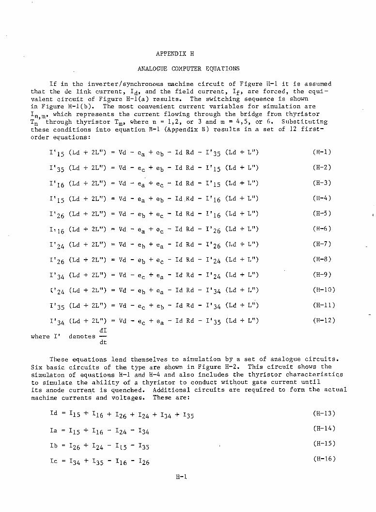
APPENDIX HANALOGUE COMPUTER EQUATIONS
If in the inverter/synchronous machine circuit of Figure H-l it is assumed that the dc link current, 1 , and the field current, If, are forced, the equivalent circuit of Figure H-l(a) results. The switching sequence is shown in Figure H-l(b). The most convenient current variables for simulation are In m, which represents the current flowing through the bridge from thyristor Tn through thyristor Tm, where n = 1,2, or 3 and m = 4,5, or 6 . Substituting these conditions into equation B-l (Appendix B) results in a set of 12 first-order equations:
I ' 15 (Ld + 2L") = Vd - ea + eb - Id Rd - I ' 35 (Ld + L") (H-l)I ' 3 5 (Ld + 2L") = Vd - ec + eb - Id Rd - I ' i 5 (Ld + L") (H-2)I ' 16 (Ld + 2L") = Vd - ea + ec - Id Rd - I1i 5 (Ld + L") (H-3)I ' 15 (Ld + 2L") = Vd - ea + eb - Id Rd - 1'ig (Ld + L") (H-4)I125 (Ld + 2L") = Vd - eb + ec - Id Rd - I ' 16 (Ld + L") (H-5)It16 (Ld + 2L") = Vd - ea + ec - Id Rd - I ’ 2 6 (Ld + L") (H-6 )
I ' 24 (Ld + 2L") = Vd - eb + ea - Id Rd - I’26 (Ld + L") (H-7)I ’ 26 (Ld + 2L") = Vd - eb + ec - Id Rd - I ’ 2 4 (Ld + L") (H-8 )I ’ 34 (Ld + 2L") = Vd - ec + ea - Id Rd - 1*24 (Ld + L") (H-9)1124 (Ld + 2L") = Vd - eb + ea - Id Rd - I ’ 34 (Ld + L") (H-10)I ' 35 (Ld + 2L") = Vd - ec + eb - Id Rd - 1 * 3 4 (Ld + L") (H-ll)I ' 3 4 (Ld + 2L") = Vd - ec + ea - Id Rd - I ' 35 (Ld + L") (H-12)
dlwhere I' denotes — dt
These equations lend themselves to simulation by a set of analogue circuits. Six basic circuits of the type are shown in Figure H—2. This circuit shows the simulaton of equations H-l and H-4 and also includes the thyristor characteristics to simulate the ability of a thyristor to conduct without gate current until its anode current is quenched. Additional circuits are required to form the actual machine currents and voltages. These are:
Id I15 + I16 + L26 + I24 + I34 + I35
Ia = I15 + Ii6 “ I24 “ I34
Ib = I26 + x24 " x15 " x35Ic = I34 + I35 - I16 - I2 6
(H-13) (H-14) (H-15) (H-16)
H-l
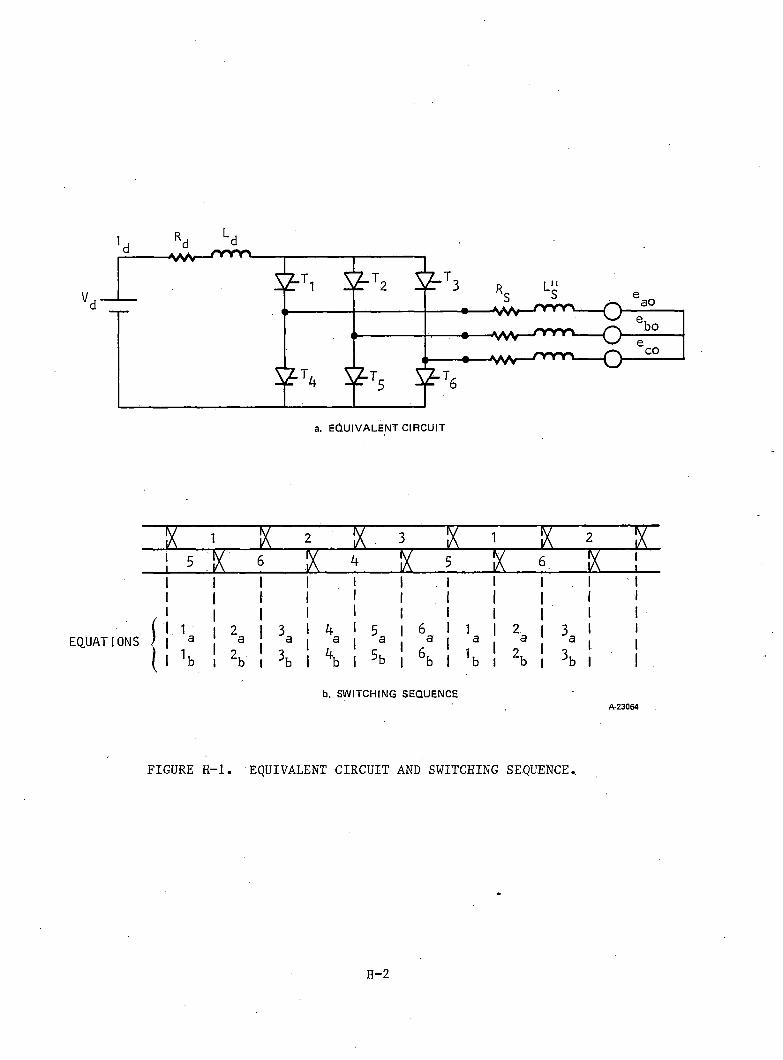
EQUATIONS
ix i " v r y . t . % ~ x ^ xn E T £ £
I 3a*b |
a5b
1 | 2 | 3a a 1 i1 I 2 * 3b I b | 3 l
b. S W IT C H IN G S E Q U E N C EA -2 3 0 6 4
FIGURE H—1. EQUIVALENT CIRCUIT AND SWITCHING SEQUENCE,
H-2
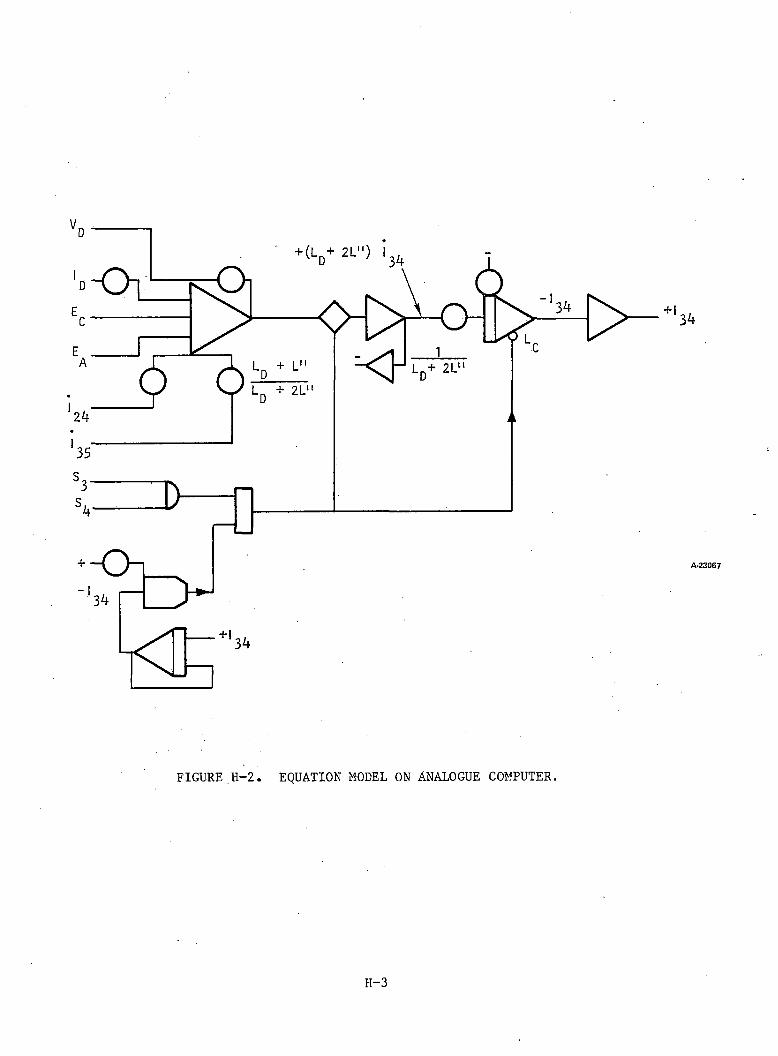
VD ---- —
'd - O ]EC
A
*24 r6 ;
*35
3s/ >4
+ ~ 0 “ L
L-•
+ V 2L") l3l(
K i ] - 1 ld+'2l"
34
+134
A -2 3 0 6 7
FIGURE H-2. EQUATION MODEL ON ANALOGUE COMPUTER.
H-3
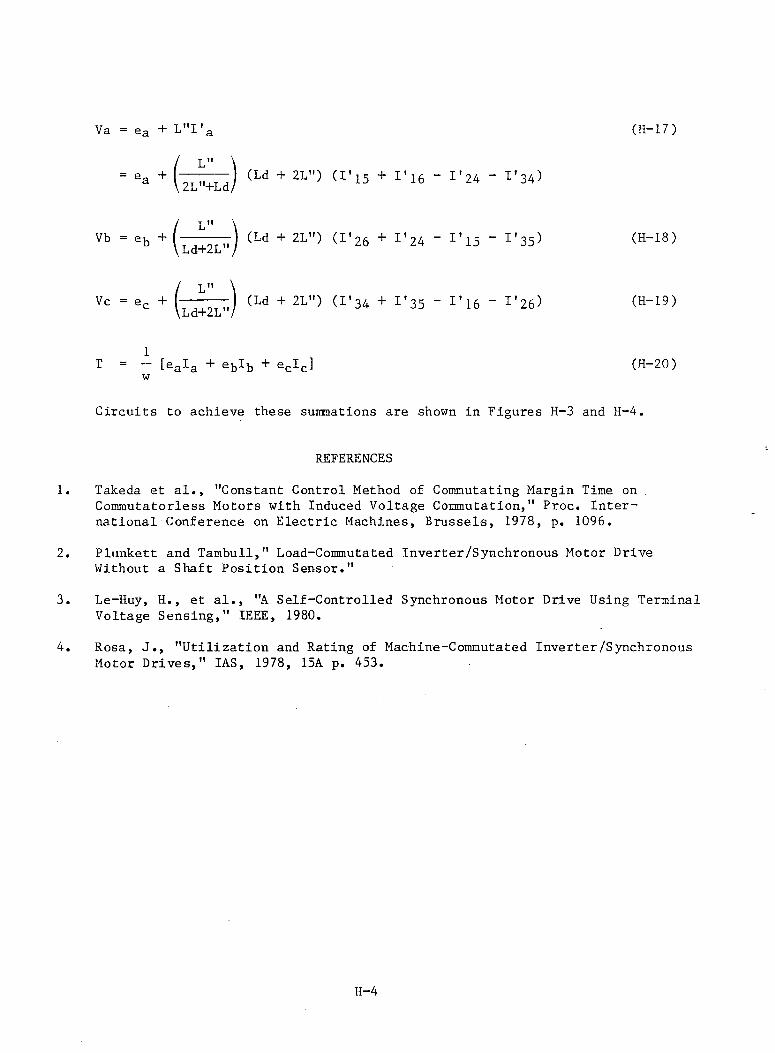
Va = ea + L"I'a
L"" ea + 2L"+Ld (Ld + 2L") (I'15 + I’i6 - I'24 - I'34>
Vb = 6b + ( l ^ 7) (Ld + (I’26 + 1,24 “ 1,15 ~ r35)
(H-17)
(H-18)
L"Vc = ec + (Ld + 2L"> ^'34 + I'35 - 1 ’ 16 - I'26) (H-19)
tea^a eb^b ec^c w (H-20)
Circuits to achieve these summations are shown in Figures H-3 and H-4,
REFERENCES
1. Takeda et al., "Constant Control Method of Commutating Margin Time on . Commutatorless Motors with Induced Voltage Commutation," Proc. International Conference on Electric Machines, Brussels, 1978, p. 1096.
2. Plunkett and Tambull," Load-Commutated Inverter/Synchronous Motor Drive Without a Shaft Position Sensor."
3. Le-Huy, H., et al., "A Self-Controlled Synchronous Motor Drive Using Terminal Voltage Sensing," IEEE, 1980.
4. Rosa, J., "Utilization and Rating of Machine-Commutated Inverter/Synchronous Motor Drives," IAS, 1978, 15A p. 453.
H-4
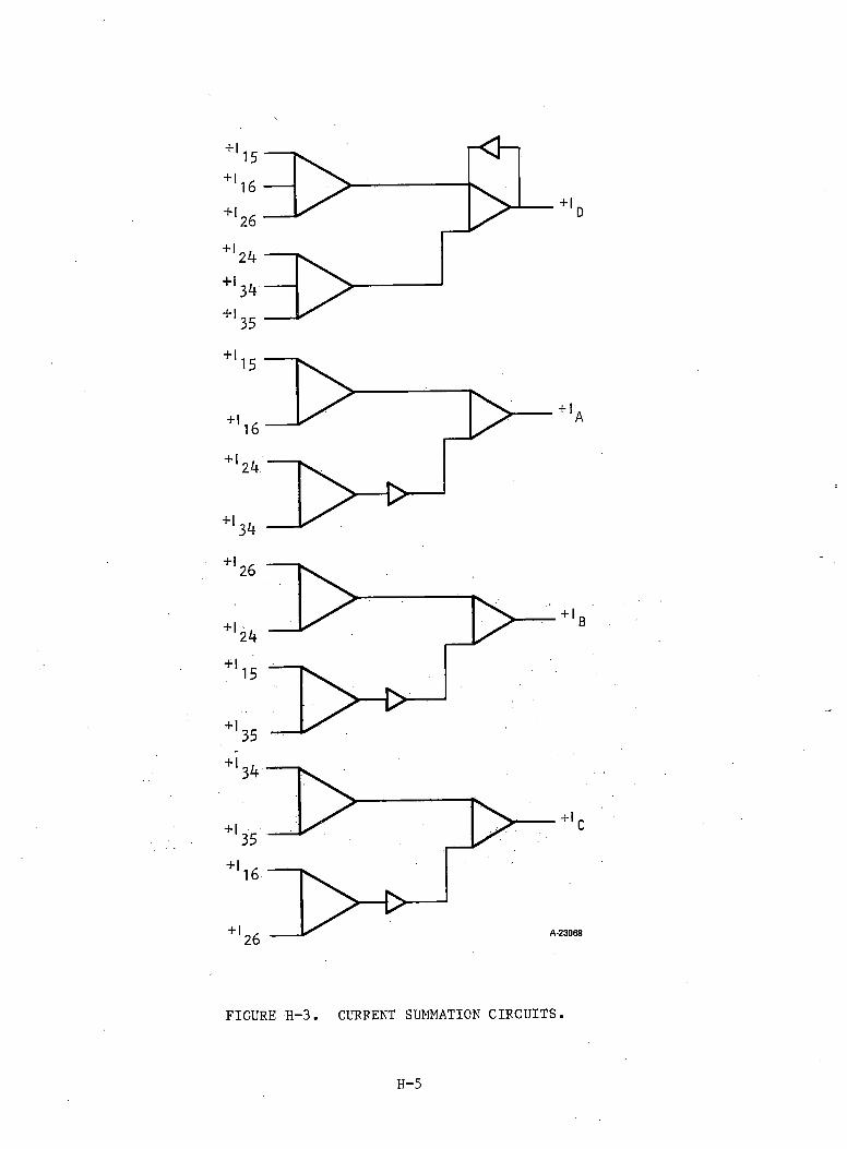
FIGURE H—3. CURRENT SUMMATION CIRCUITS.
H-5
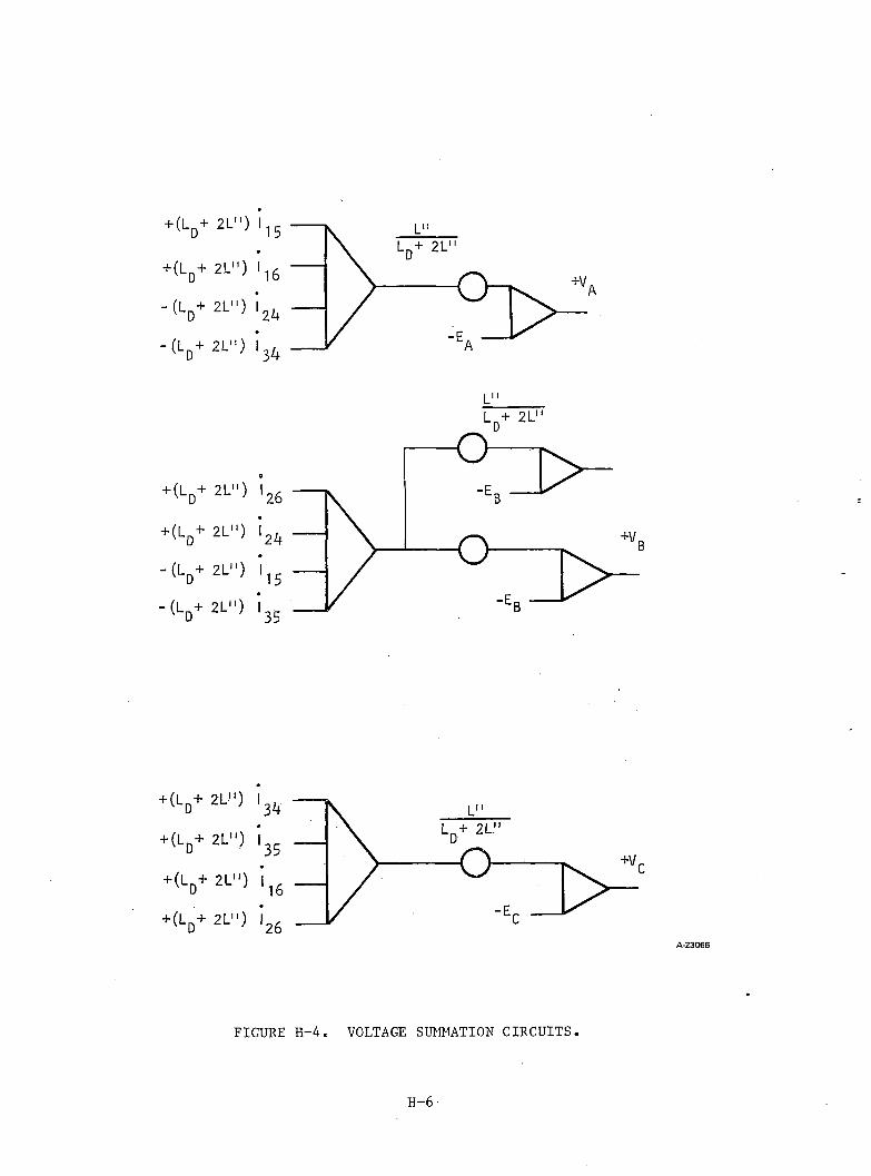
D
H'D
'D
+ V’ D
■d h
'D
+"D
l d h
FIGURE H-4. VOLTAGE SUMMATION CIRCUITS.
A -2 3 0 6 6
H-6 -

Based on MUI on.sf7iWMacdwan9.anid Technology (Final Report), 1981 Graham W McLean