Embed Size (px)
Citation preview
1
Aircraft Design: A Systems Engineering Approach, M. Sadraey, Wiley, 2012
Chapter 7
Fuselage Design
Figures
2
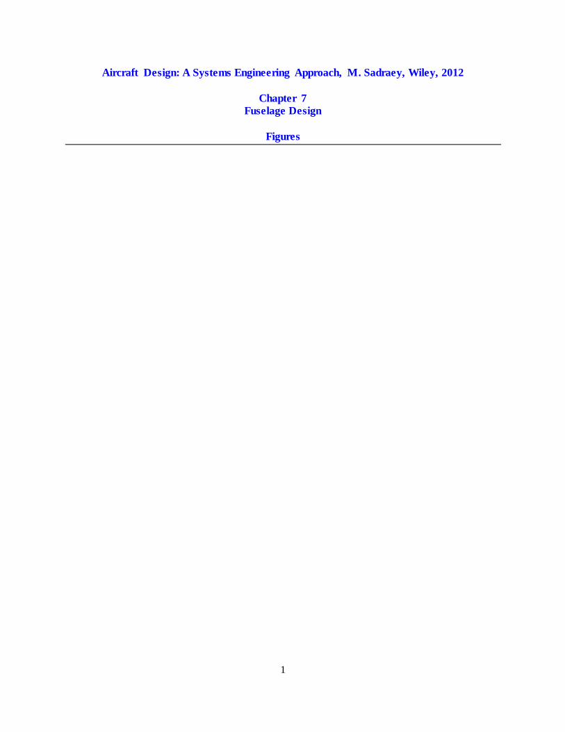
Figure 7.1. Fuselage design flowchart
No
Select fuselage configuration and internal arrangement
Identify payload and operational requirements/prioritize fuselage design requirements
Lofting (determine cross section and diameter at each station)
Is this fuselage
satisfying the design
requirements?
Yes
Optimization
Design internal space for items/components which are allocated
to be inside fuselage (e.g. fuel tank, landing gear, and engine)
Determine optimum fuselage length
Design passenger cabin/ cargo compartment
Design nose section
Design rear section
Design pilot(s) and crew members’ cockpit
Design doors/windows
3
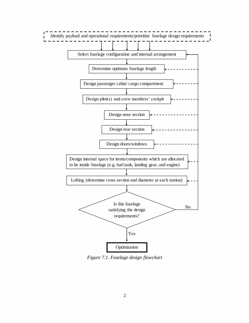
1. Large transport aircraft
2. Fighter aircraft
3. Light GA aircraft
4. Glider
Figure 7.2. Four generic fuselage configurations
1. Low wing passenger aircraft
2. Fighter aircraft
Figure 7.3. Internal arrangement of a civil passenger and a fighter aircraft
Cockpit
Cockpit Passenger cabin
Systems Cargo Fuel tanks Cargo
Systems
Landing gear Wing box Landing gear
Jet Engine Systems
Landing gear
Radar
4
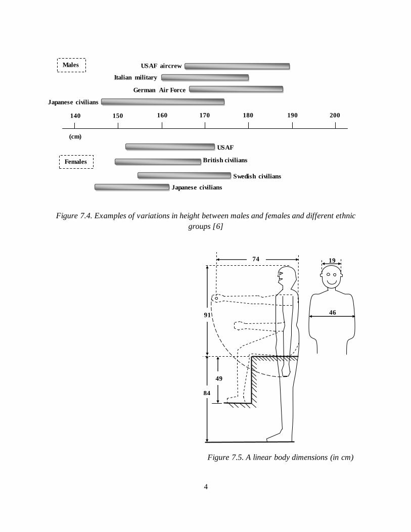
Figure 7.4. Examples of variations in height between males and females and different ethnic
groups [6]
Figure 7.5. A linear body dimensions (in cm)
Swedish civilians
British civilians
Japanese civilians
USAF
USAF aircrew
Italian military
German Air Force
Japanese civilians
(cm)
140 160 150 170 180 190 200
0
Males
Females
46
c
m
19
c
m
91 c
m
84
c
m
49
c
m
74
c
m
5
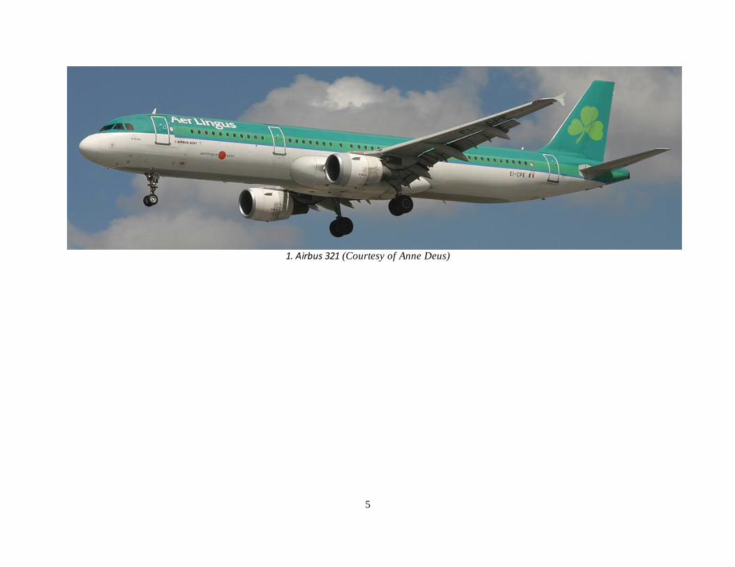
1. Airbus 321 (Courtesy of Anne Deus)
6
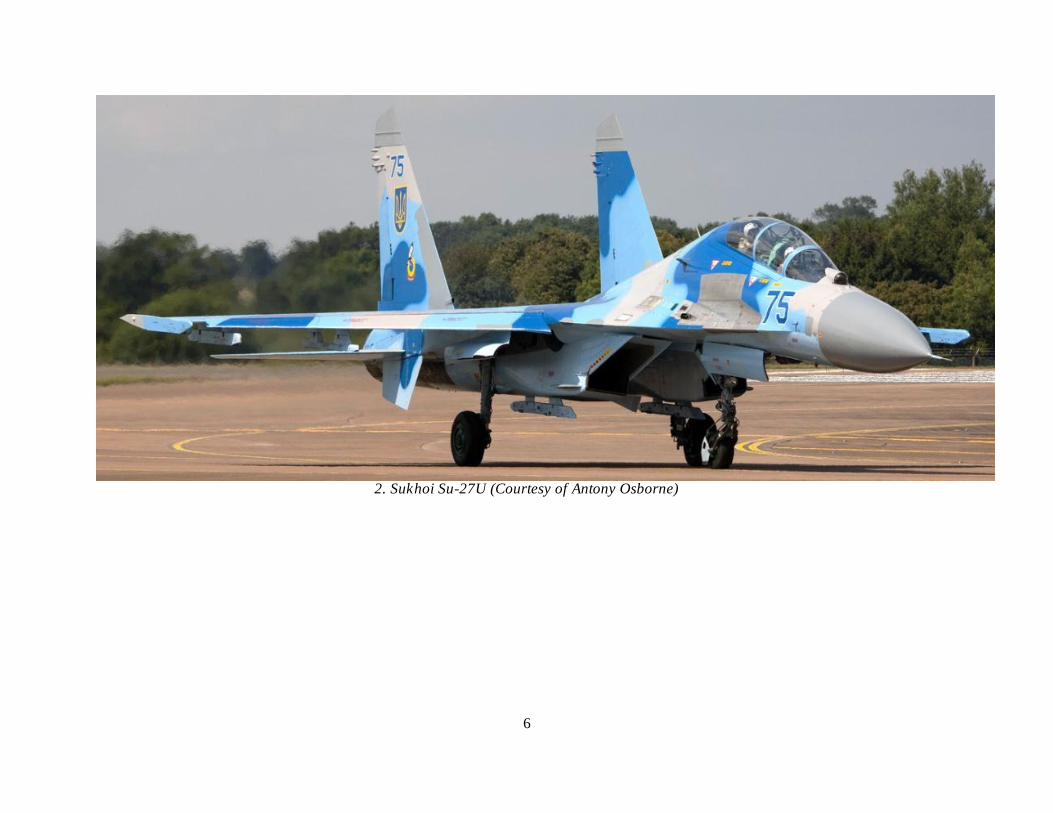
2. Sukhoi Su-27U (Courtesy of Antony Osborne)
7
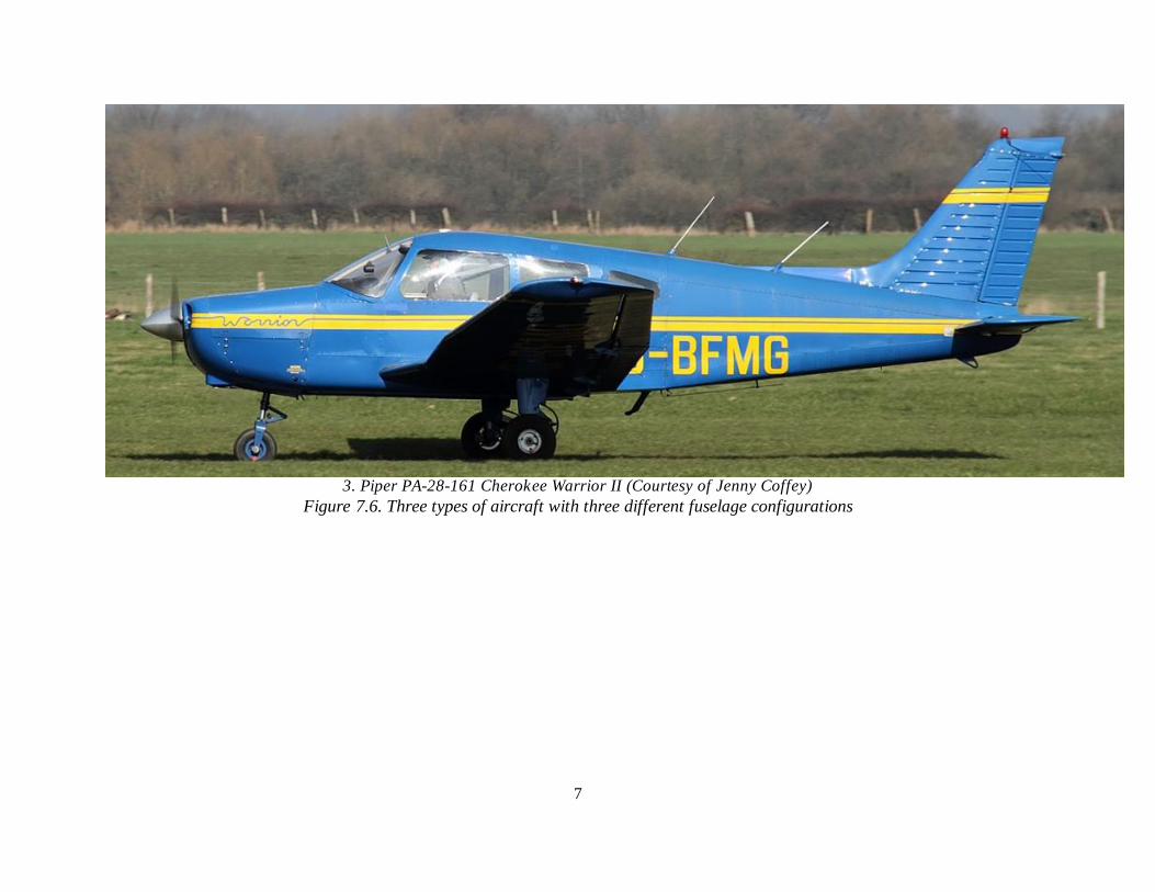
3. Piper PA-28-161 Cherokee Warrior II (Courtesy of Jenny Coffey)
Figure 7.6. Three types of aircraft with three different fuselage configurations
8
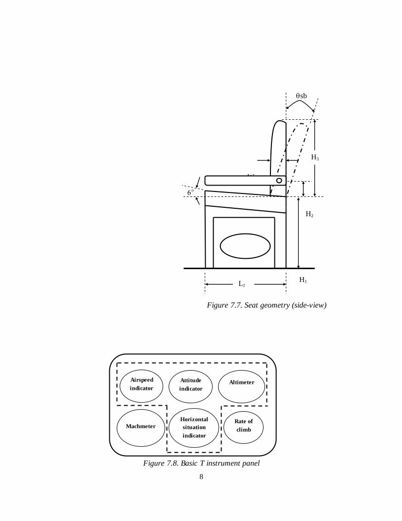
Figure 7.7. Seat geometry (side-view)
Figure 7.8. Basic T instrument panel
W1
H2
sb
H1
H3
L1
Airspeed
indicator
Attitude
indicator Altimeter
Horizontal
situation
indicator
Rate of
climb Machmeter
9
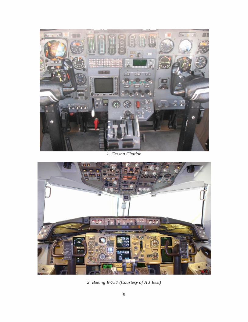
1. Cessna Citation
2. Boeing B-757 (Courtesy of A J Best)
10
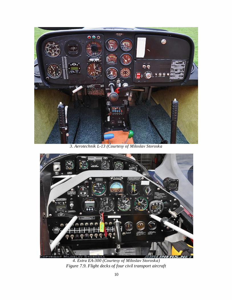
3. Aerotechnik L-13 (Courtesy of Miloslav Storoska
4. Extra EA-300 (Courtesy of Miloslav Storoska)
Figure 7.9. Flight decks of four civil transport aircraft
11
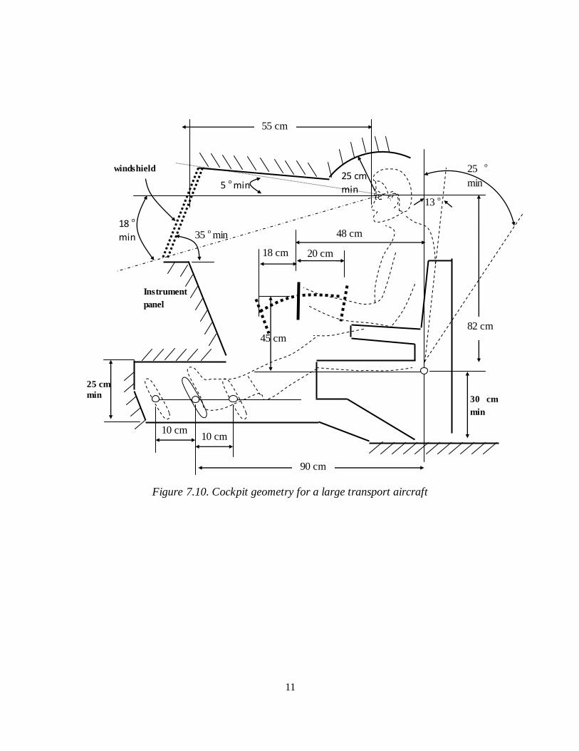
Figure 7.10. Cockpit geometry for a large transport aircraft
30 cm
min
5 o min
25 o
min
Instrument
panel
18 cm
48 cm
windshield
20 cm
35 o min
10 cm 10 cm
45 cm
25 cm
min 13
o
25 cm
min
90 cm
18 o
min
55 cm
82 cm
12
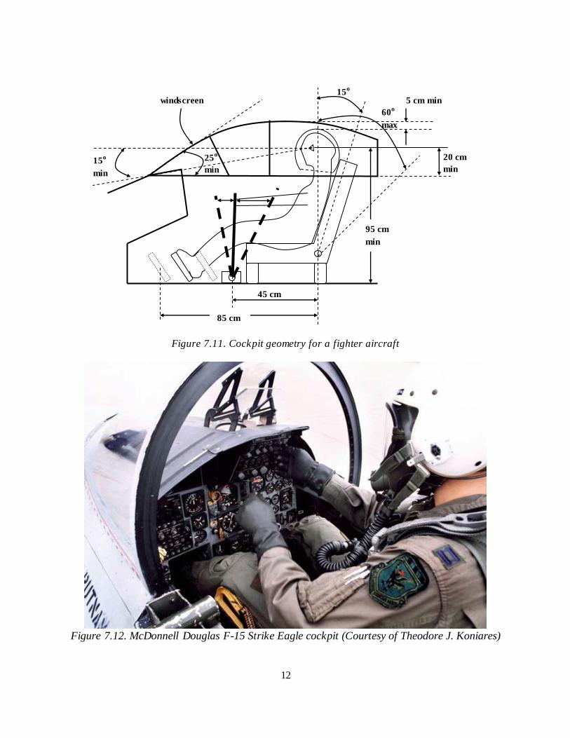
Figure 7.11. Cockpit geometry for a fighter aircraft
Figure 7.12. McDonnell Douglas F-15 Strike Eagle cockpit (Courtesy of Theodore J. Koniares)
20 cm
min
25o
min 15
o
min
15o
60o
max
45 cm
85 cm
5 cm min
95 cm
min
windscreen
13
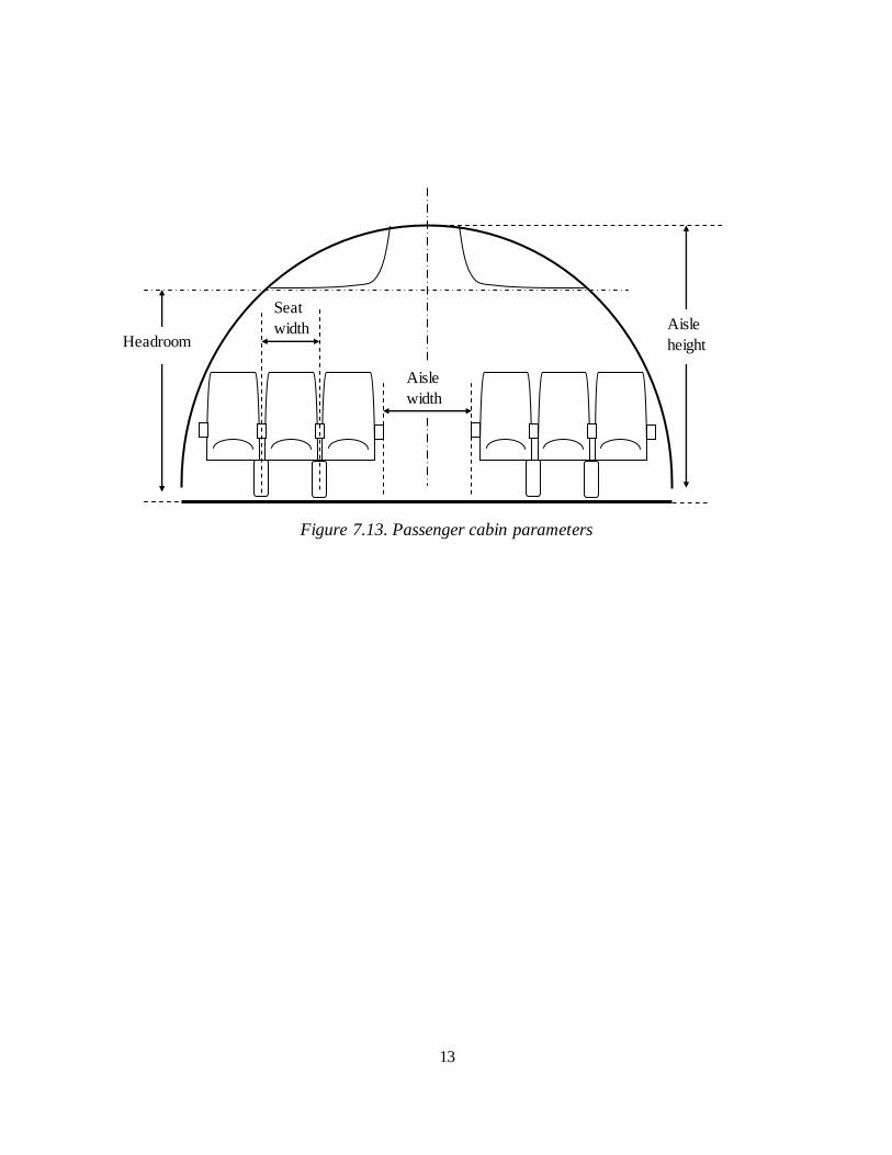
Figure 7.13. Passenger cabin parameters
Aisle
height Headroom
Aisle
width
Seat
width
14
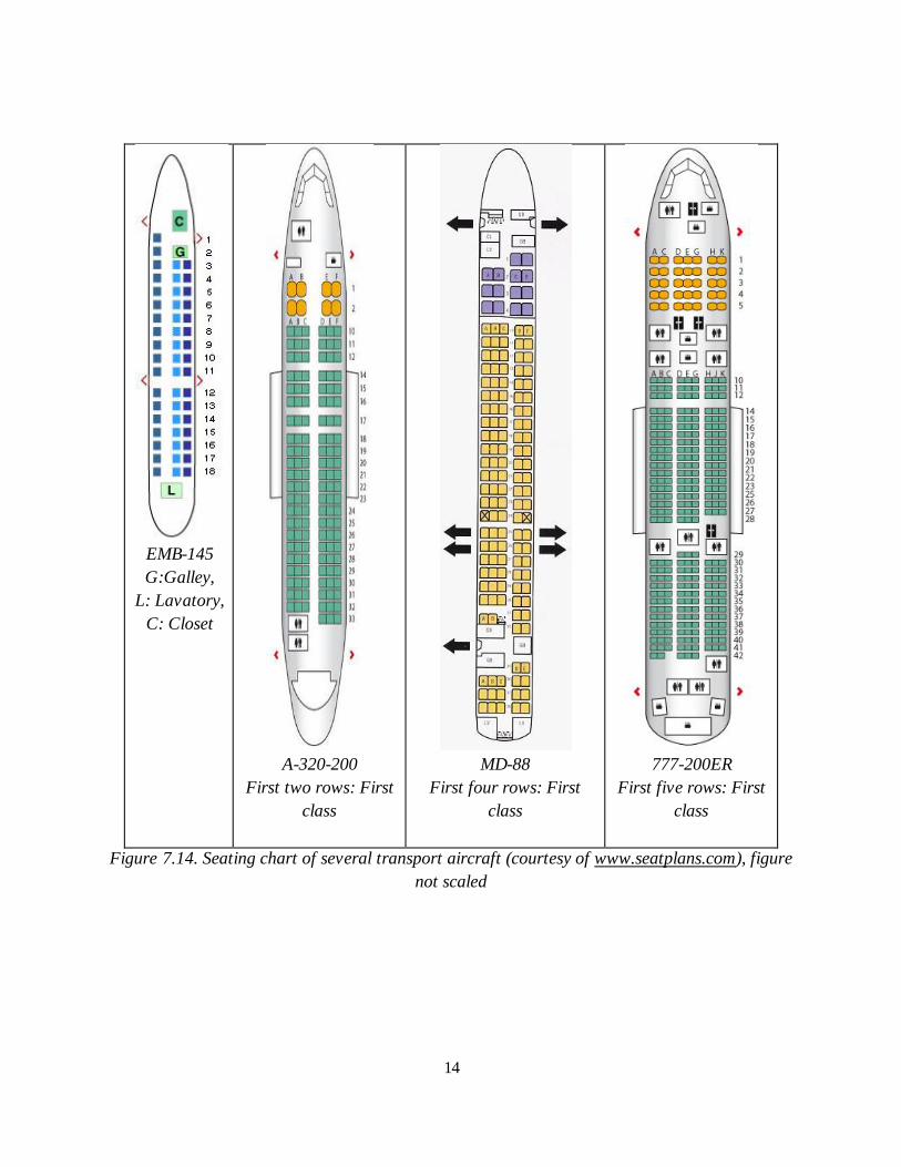
EMB-145
G:Galley,
L: Lavatory,
C: Closet
A-320-200
First two rows: First
class
MD-88
First four rows: First
class
777-200ER
First five rows: First
class
Figure 7.14. Seating chart of several transport aircraft (courtesy of www.seatplans.com), figure
not scaled
15
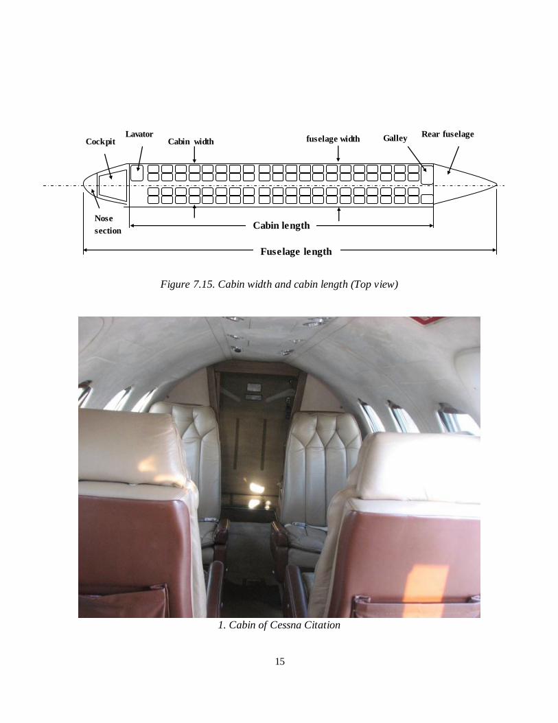
Figure 7.15. Cabin width and cabin length (Top view)
1. Cabin of Cessna Citation
fuselage width Cabin width
Cabin length
Rear fuselage Cockpit
Nose
section
Galley Lavator
y
Fuselage length
16
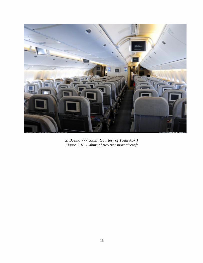
2. Boeing 777 cabin (Courtesy of Toshi Aoki)
Figure 7.16. Cabins of two transport aircraft
17
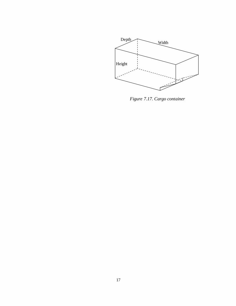
Figure 7.17. Cargo container
Height
Width Depth
18
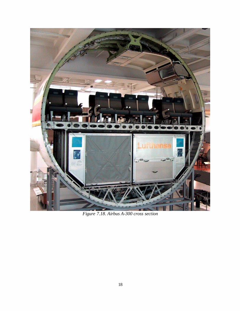
Figure 7.18. Airbus A-300 cross section
19
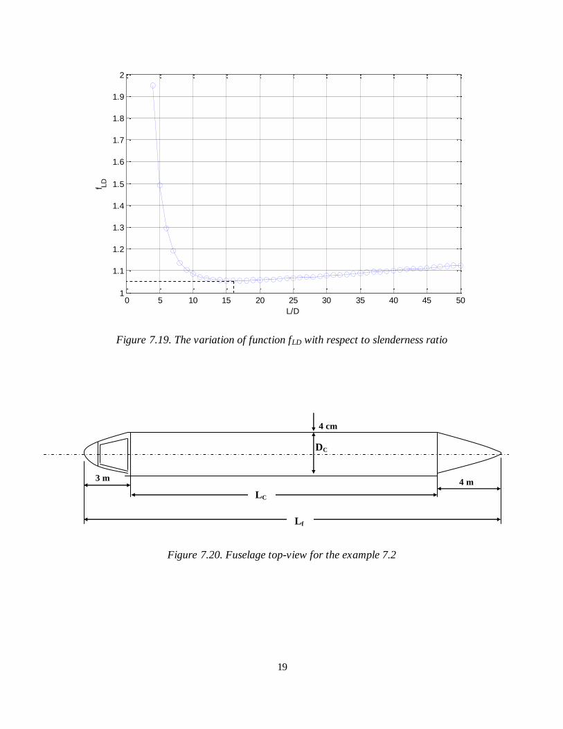
Figure 7.19. The variation of function fLD with respect to slenderness ratio
Figure 7.20. Fuselage top-view for the example 7.2
0 5 10 15 20 25 30 35 40 45 501
1.1
1.2
1.3
1.4
1.5
1.6
1.7
1.8
1.9
2
L/D
f LD
DC
4 cm
4 m 3 m
LC
Lf
20
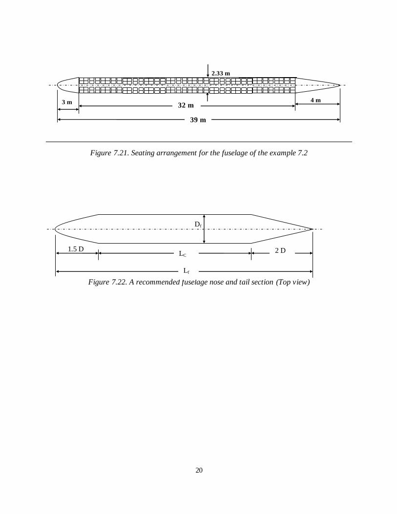
Figure 7.21. Seating arrangement for the fuselage of the example 7.2
Figure 7.22. A recommended fuselage nose and tail section (Top view)
1.5 D
2.33 m
3 m 4 m 32 m
39 m
Df
LC
Lf
2 D
21
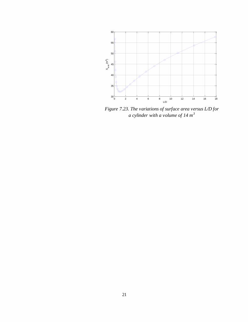
Figure 7.23. The variations of surface area versus L/D for
a cylinder with a volume of 14 m3
0 2 4 6 8 10 12 14 16 1830
35
40
45
50
55
60
L/D
Sw
et (
m2)
22
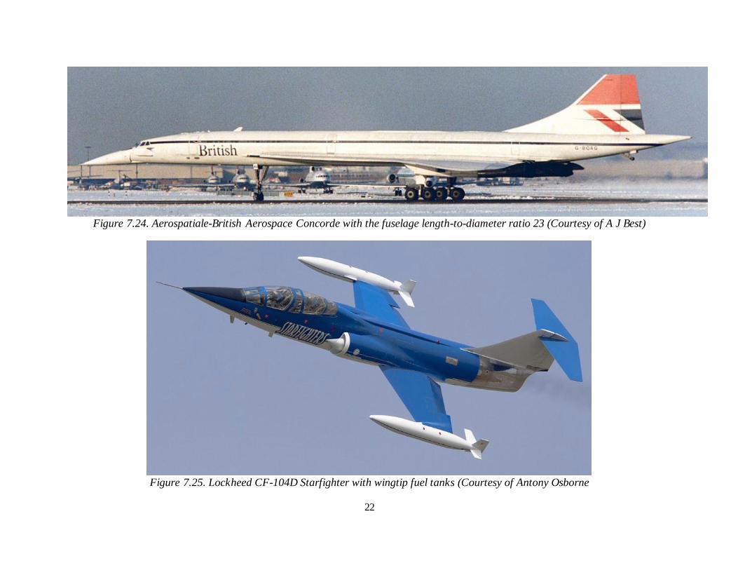
Figure 7.24. Aerospatiale-British Aerospace Concorde with the fuselage length-to-diameter ratio 23 (Courtesy of A J Best)
Figure 7.25. Lockheed CF-104D Starfighter with wingtip fuel tanks (Courtesy of Antony Osborne
23
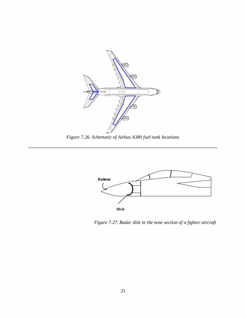
Figure 7.26. Schematic of Airbus A380 fuel tank locations
Figure 7.27. Radar dish in the nose section of a fighter aircraft
Radome
Dish
24
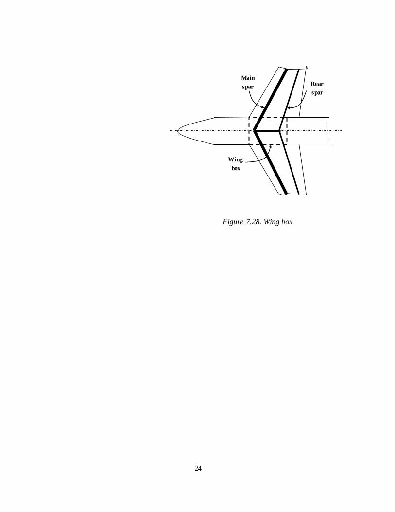
Figure 7.28. Wing box
Main
spar Rear
spar
Wing
box
25
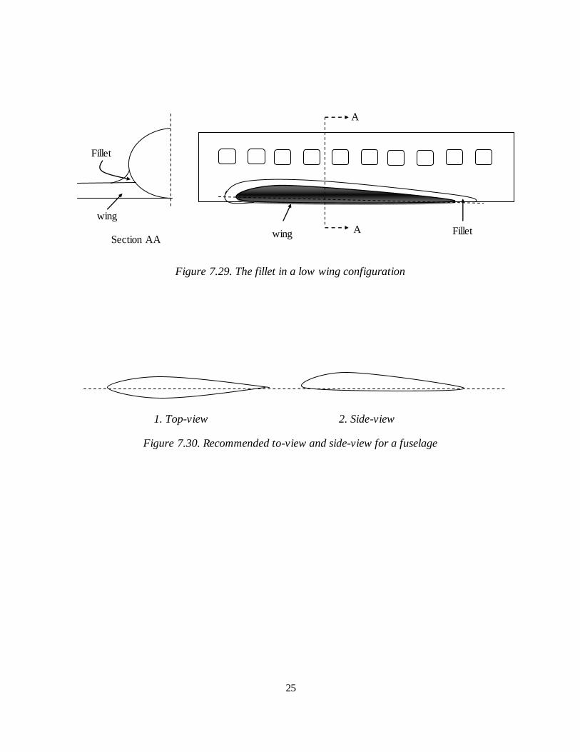
Figure 7.29. The fillet in a low wing configuration
1. Top-view 2. Side-view
Figure 7.30. Recommended to-view and side-view for a fuselage
A
A
wing Fillet
wing
Fillet
Section AA
26
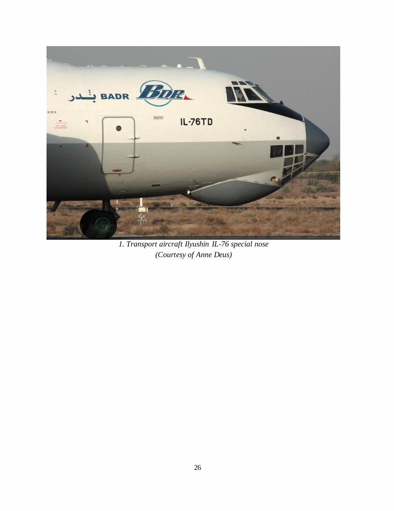
1. Transport aircraft Ilyushin IL-76 special nose
(Courtesy of Anne Deus)
27
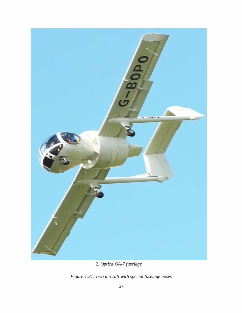
2. Optica OA-7 fuselage
Figure 7.31. Two aircraft with special fuselage noses
28
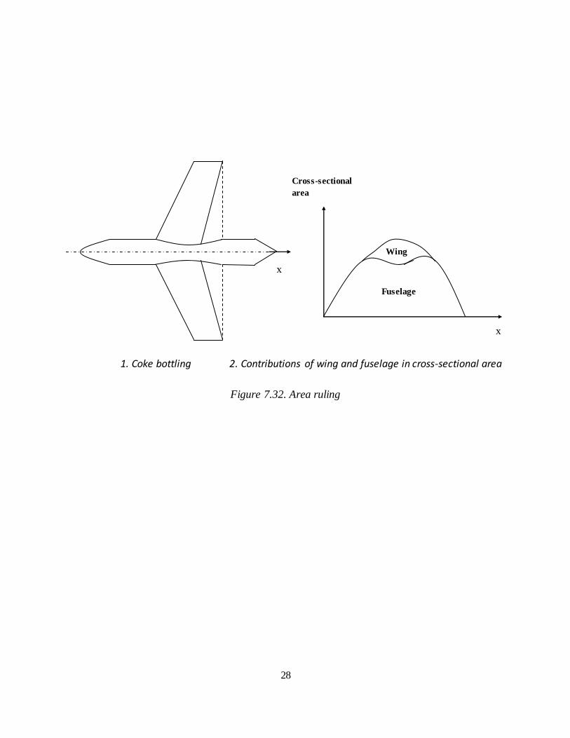
1. Coke bottling 2. Contributions of wing and fuselage in cross-sectional area
Figure 7.32. Area ruling
Wing
Fuselage
Cross-sectional
area
x
x
29
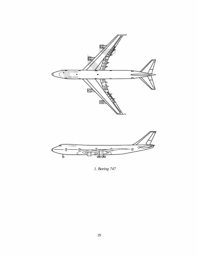
1. Boeing 747
30
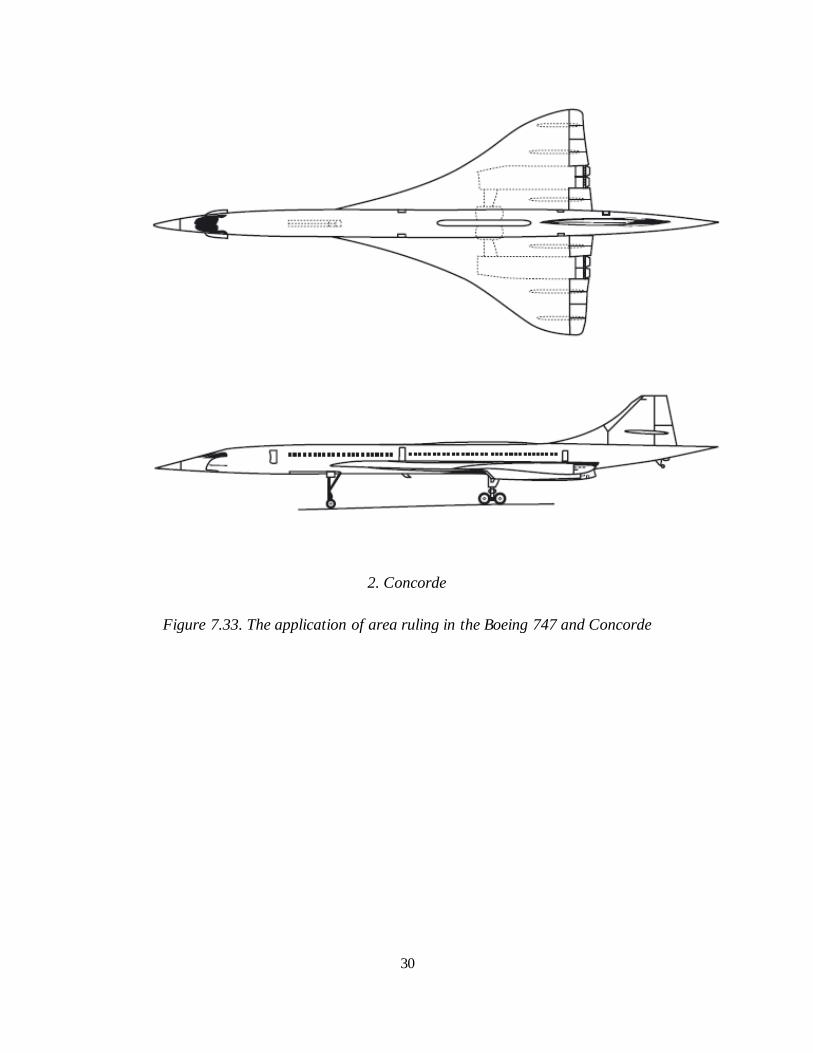
2. Concorde
Figure 7.33. The application of area ruling in the Boeing 747 and Concorde
31
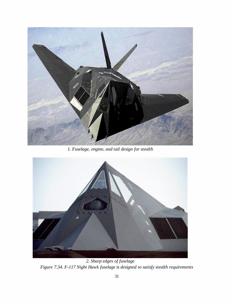
1. Fuselage, engine, and tail design for stealth
2. Sharp edges of fuselage
Figure 7.34. F-117 Night Hawk fuselage is designed to satisfy stealth requirements
32
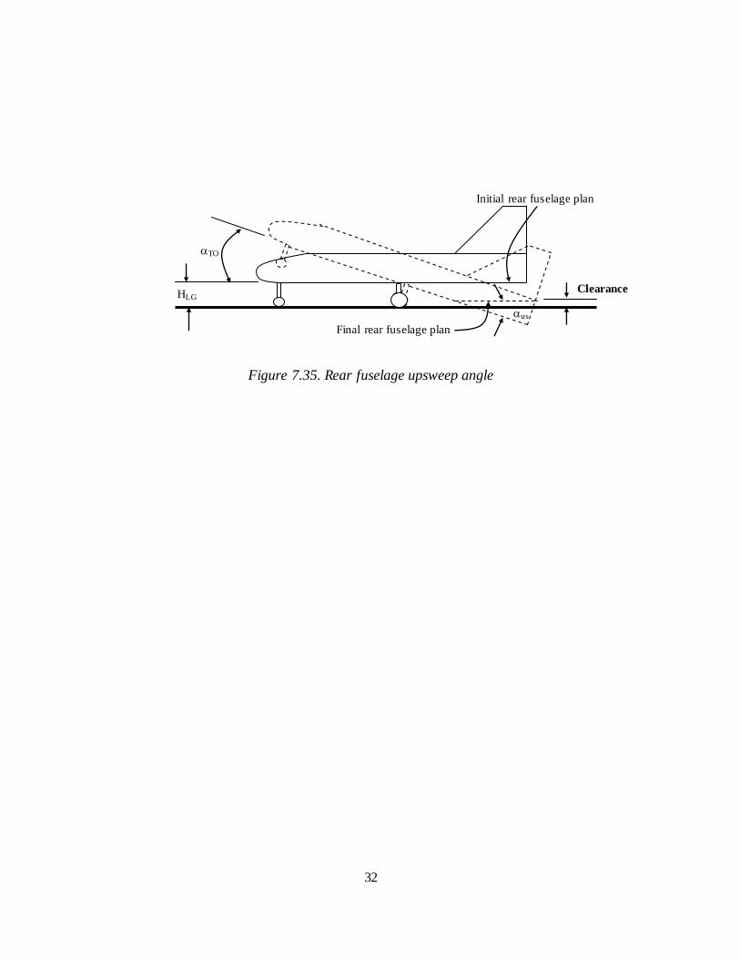
Figure 7.35. Rear fuselage upsweep angle
Initial rear fuselage plan
HLG
us
TO
Clearance
Final rear fuselage plan
33
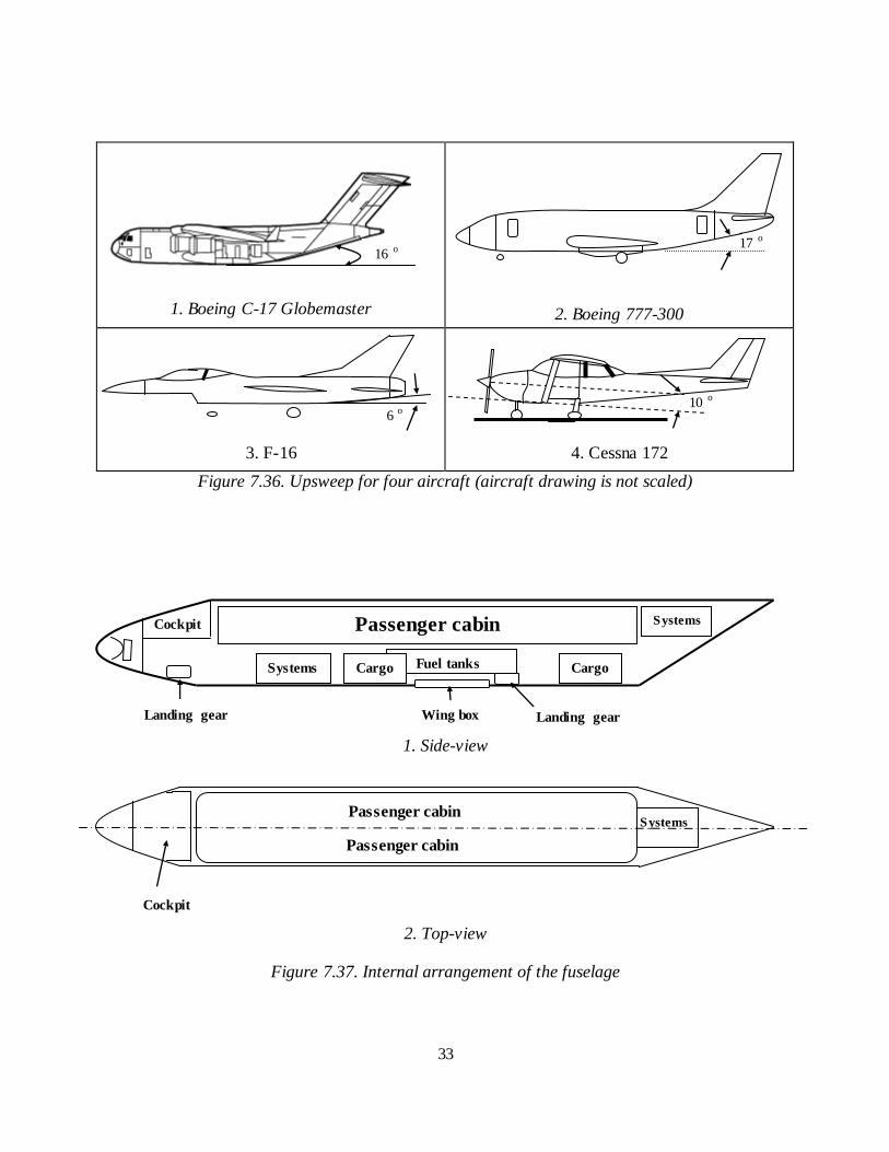
1. Boeing C-17 Globemaster
2. Boeing 777-300
3. F-16
4. Cessna 172
Figure 7.36. Upsweep for four aircraft (aircraft drawing is not scaled)
1. Side-view
2. Top-view
Figure 7.37. Internal arrangement of the fuselage
Systems
6 o
17 o
16
o
Cockpit Passenger cabin
Systems Fuel tanks Cargo
Systems
Landing gear Wing box Landing gear
Cargo
Passenger cabin
Passenger cabin
Cockpit
10 o
34
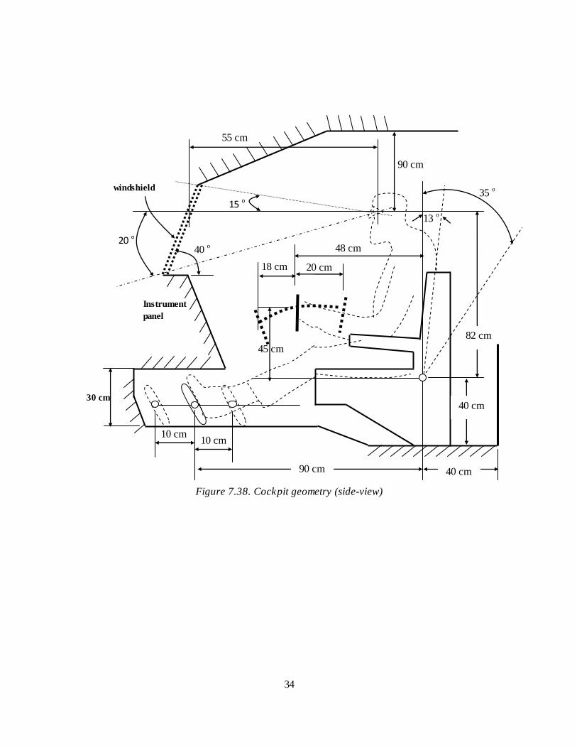
Figure 7.38. Cockpit geometry (side-view)
90 cm
55 cm
15 o 35
o
Instrument
panel
18 cm
48 cm
windshield
20 cm
40 o
10 cm 10 cm
45 cm
13 o
30 cm
90 cm
20 o
82 cm
40 cm
40 cm
35
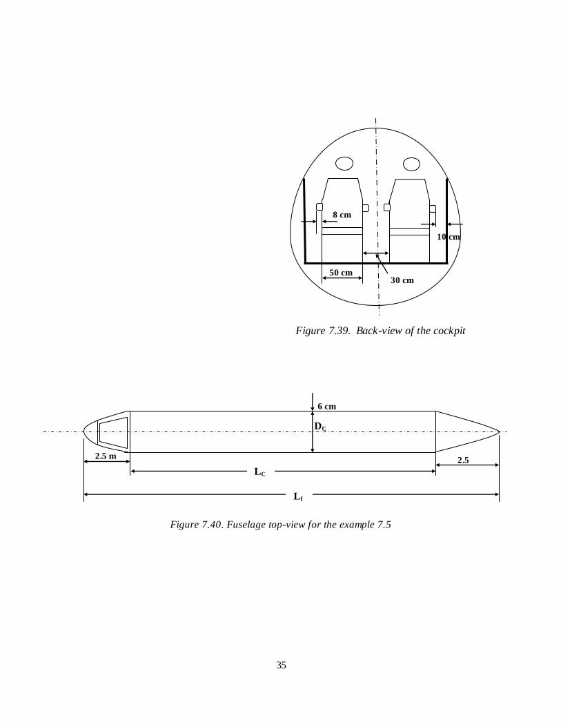
Figure 7.39. Back-view of the cockpit
Figure 7.40. Fuselage top-view for the example 7.5
8 cm
10 cm
50 cm 30 cm
DC
6 cm
2.5
m
2.5 m
LC
Lf
36
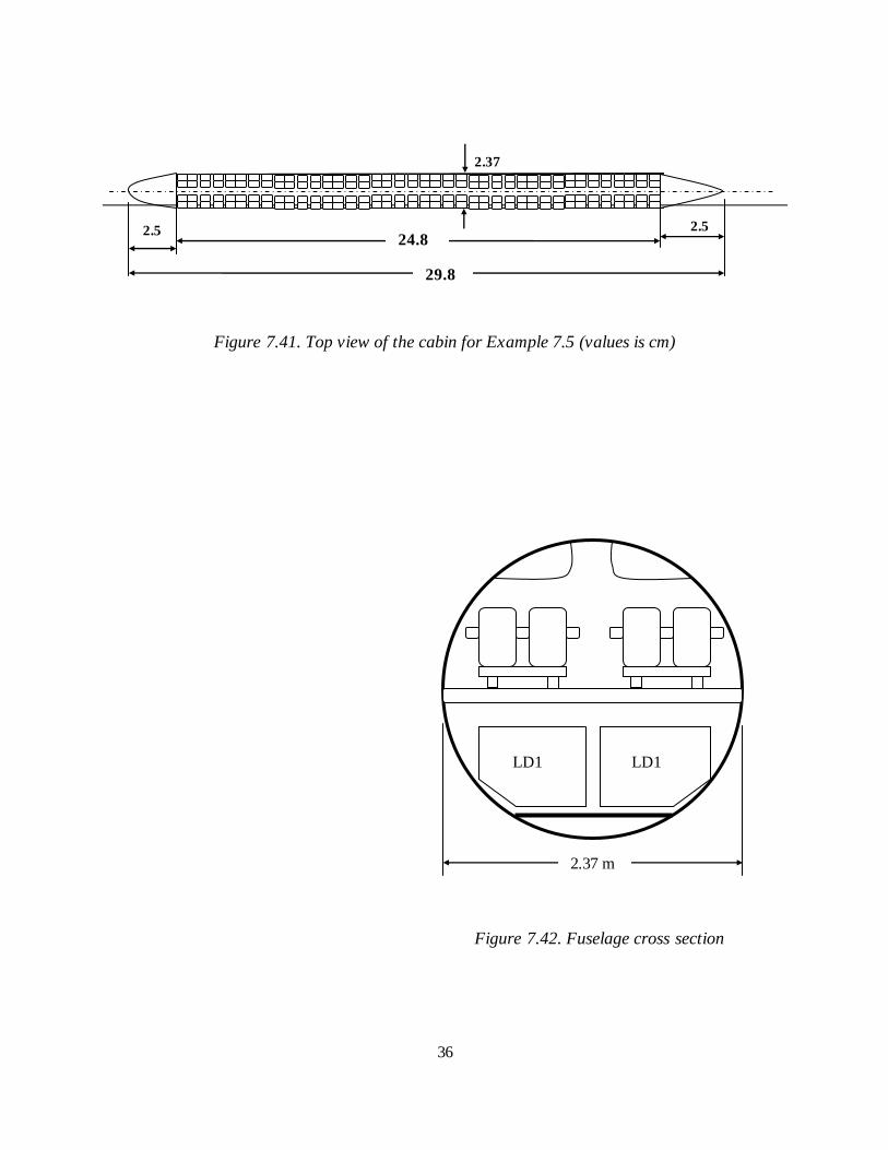
Figure 7.41. Top view of the cabin for Example 7.5 (values is cm)
Figure 7.42. Fuselage cross section
2.5
m
2.37
2.5
m 24.8
m 29.8
2.37 m
LD1 LD1
37
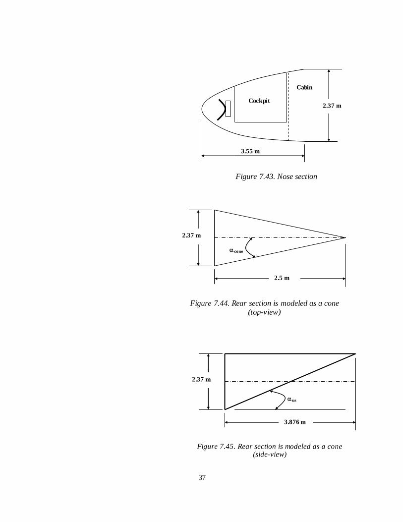
Figure 7.43. Nose section
Figure 7.44. Rear section is modeled as a cone (top-view)
Figure 7.45. Rear section is modeled as a cone (side-view)
3.55 m
2.37 m Cockpit
Cabin
cone
2.37 m
2.5 m
us
2.37 m
3.876 m
m
38
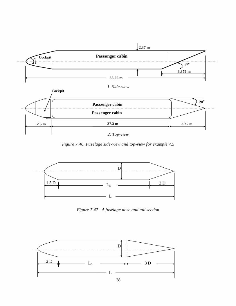
1. Side-view
2. Top-view
Figure 7.46. Fuselage side-view and top-view for example 7.5
Figure 7.47. A fuselage nose and tail section
2 D
D
LC 3 D
L
3.876 m
2.5 m 27.3 m
20o
17o
2.37 m
Cockpit Passenger cabin
Passenger cabin
Passenger cabin
Cockpit
33.05 m
3.25 m
2 D 1.5 D
D
L
LC
39
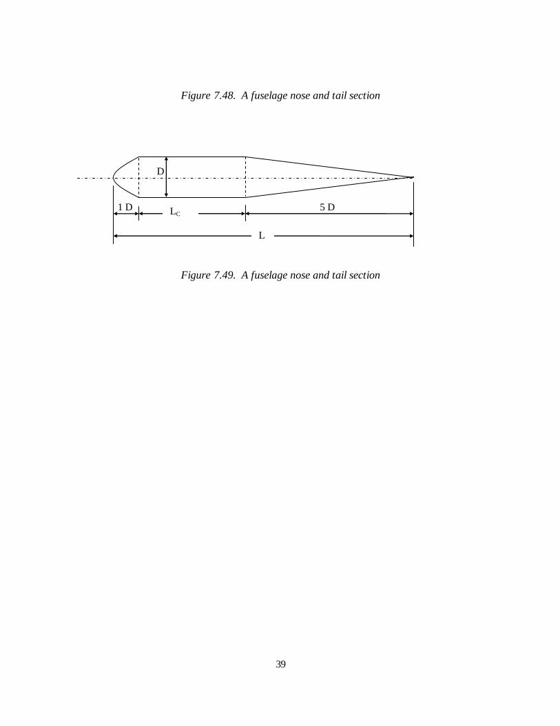
Figure 7.48. A fuselage nose and tail section
Figure 7.49. A fuselage nose and tail section
5 D 1 D
D
LC
L