Embed Size (px)
DESCRIPTION
Â
Citation preview

DESIGN STUDIO AIRS K E T C H B O O KREBECCA MAHONEY
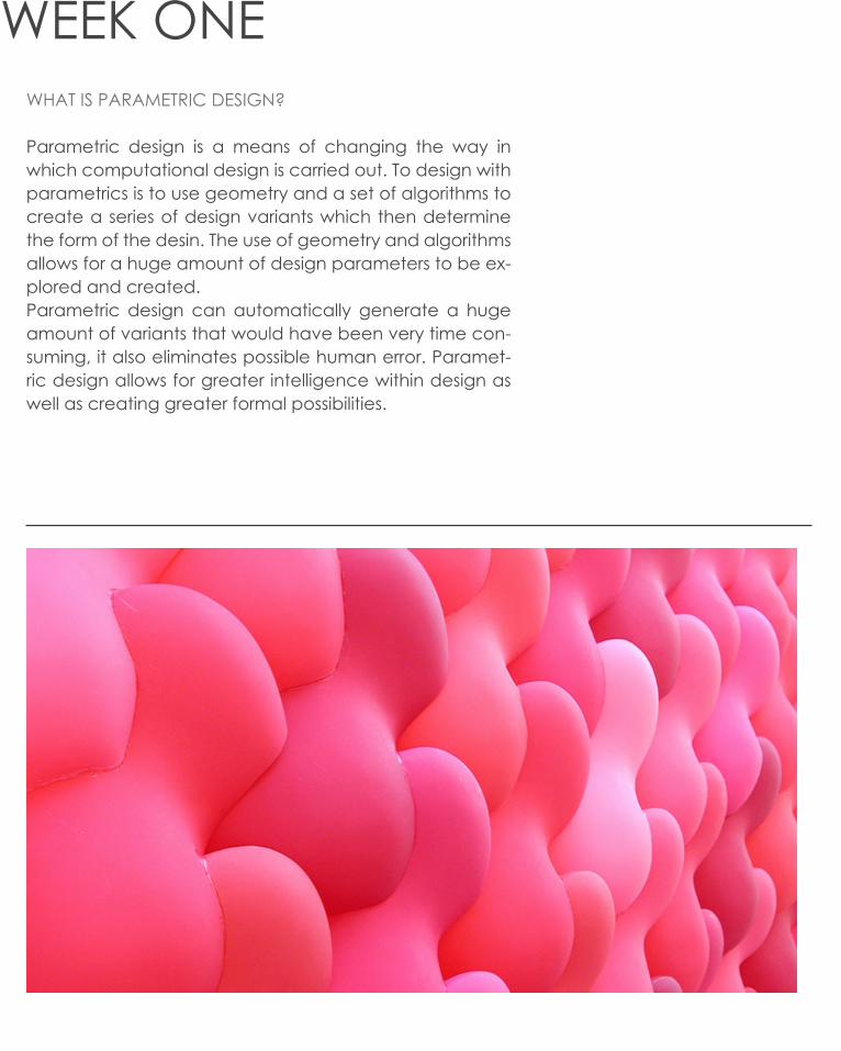
WEEK ONEWHAT IS PARAMETRIC DESIGN?
Parametric design is a means of changing the way in which computational design is carried out. To design with parametrics is to use geometry and a set of algorithms to create a series of design variants which then determine the form of the desin. The use of geometry and algorithms allows for a huge amount of design parameters to be ex-plored and created. Parametric design can automatically generate a huge amount of variants that would have been very time con-suming, it also eliminates possible human error. Paramet-ric design allows for greater intelligence within design as well as creating greater formal possibilities.

The weekly task was to create a series of loft-ed curved using grasshopper. The lofts were then changed through a series of itera-tions that toggled the point place-ment, creating various forms.
CURVE x4]LOFT
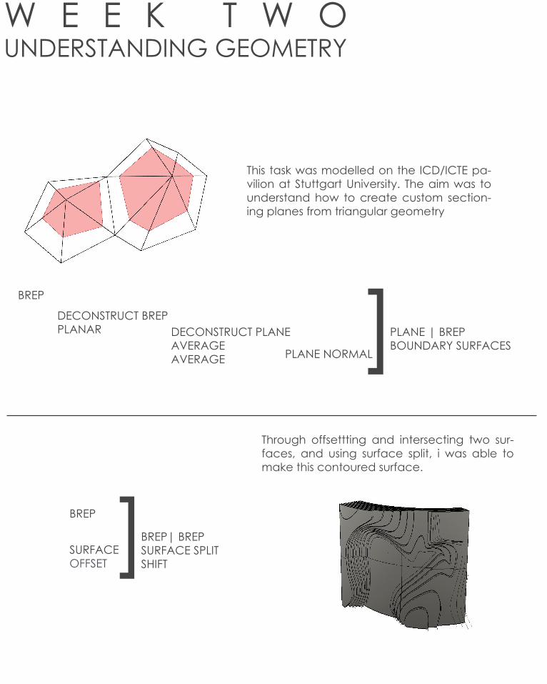
W E E K T W OUNDERSTANDING GEOMETRY
This task was modelled on the ICD/ICTE pa-vilion at Stuttgart University. The aim was to understand how to create custom section-ing planes from triangular geometry
Through offsettting and intersecting two sur-faces, and using surface split, i was able to make this contoured surface.
BREP
DECONSTRUCT BREPPLANAR DECONSTRUCT PLANE
AVERAGEAVERAGE PLANE NORMAL]PLANE | BREP
BOUNDARY SURFACES
BREP
SURFACEOFFSET ]BREP| BREP
SURFACE SPLITSHIFT

The driftwood tutorial required me to offset a curve and extrude the offsets through an exisiting geometry. The geometry is based on the Driftwood Summer Pavilion by AA. The sur-face geometry was the culled to leave the pat-terning texture of the driftwood only. This was my favourite exercise of the week becase it taught skills that would be useful in the design of out LAGI entry. It also demonstrated the use of computational de-sign in existing pavilion design.
CURVEPERP FRAMECIRCLE
BREP
BREP| BREP OFFSET] LOFT
REGION DIFFERENCE
PARAMETER 0.90
RADIUS 0.7
OFFSET 0.19

W E E K T H R E ECREATING A GRIDSHELL
This exercise required me to create a ‘grid-shell’ in rhino. I lofted a series of curves, divid-ed their geometry and from there the aim was to create a series of alterable geodisic curves.
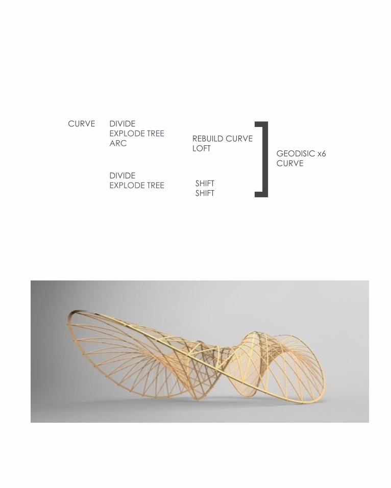
CURVE DIVIDEEXPLODE TREEARC
DIVIDEEXPLODE TREE
REBUILD CURVELOFT
SHIFTSHIFT
]GEODISIC x6CURVE

WEEK THREEGRID PATTERNING

Grid patterning is one of the typical results of parametric design in architecture. Patterns have been used in design and architecture since the start of mankind, be it on the human skin in the form of tattoos or on building surface. Traditionally in architecture pattern-ing has been used to represent a buildings ordering and symmetry 1. Over time decorative patterning and ornamentation has disap-peared from contemporary architecture, replaced by parametri-cism. Parametric patterning involves changing pattern parame-ters to fit the often double-curved host surface while maintaining a homogenous pattern. This exercise was a basic introduction into how to create a patten from a cartesian grid.
SURFACE SURFACE DIVIDEFLATTENCULL
EXTRUDE] LIST LENGTH
SERIESJITTERPARTITION ]ITEM
REGION UNIONOFFEST
U VALUE 10V VALUE 34
0 FALSE1 TRUE2 FALSE
OFFSET DISTANCE -0.05
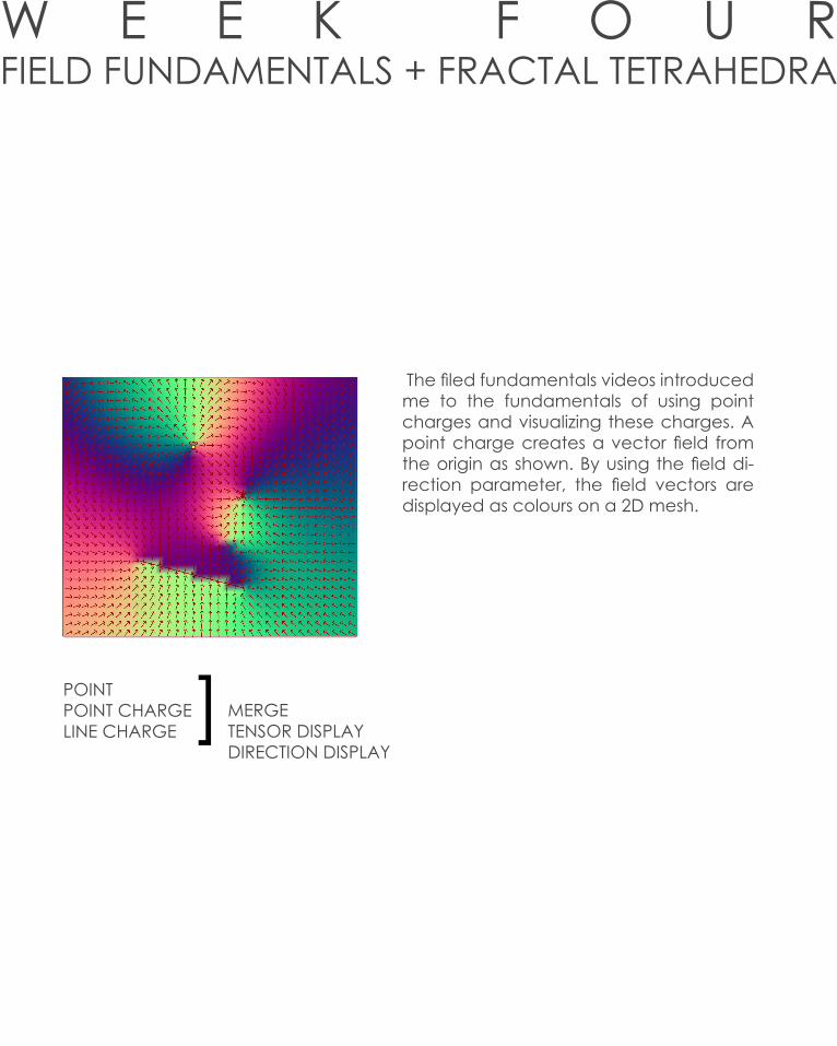
W E E K F O U RFIELD FUNDAMENTALS + FRACTAL TETRAHEDRA
The filed fundamentals videos introduced me to the fundamentals of using point charges and visualizing these charges. A point charge creates a vector field from the origin as shown. By using the field di-rection parameter, the field vectors are displayed as colours on a 2D mesh.
]POINTPOINT CHARGELINE CHARGE
MERGETENSOR DISPLAYDIRECTION DISPLAY
W E E K F O U RFIELD FUNDAMENTALS + FRACTAL TETRAHEDRA
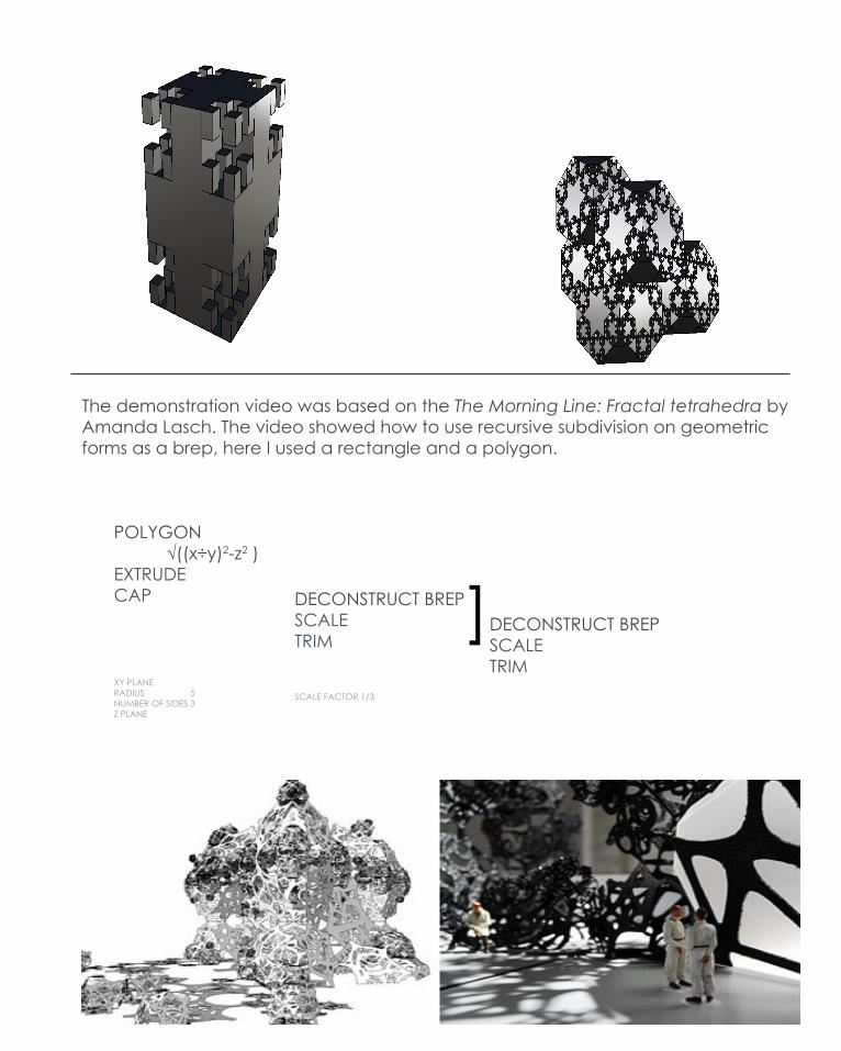
POLYGON √((x÷y)2-z2 )EXTRUDECAP
XY PLANERADIUS 5NUMBER OF SIDES 3Z PLANE
DECONSTRUCT BREPSCALETRIM
SCALE FACTOR 1/3
DECONSTRUCT BREPSCALETRIM
]
The demonstration video was based on the The Morning Line: Fractal tetrahedra by Amanda Lasch. The video showed how to use recursive subdivision on geometric forms as a brep, here I used a rectangle and a polygon.

W E E K F O U RRESEARCH FIELD + CASE STUDY ONE- SEROUSSI PAVILION


CURVEDIVIDE POINT
CHARGE
CIRCLEDIVIDE ] CURVE
DIVIDERANGE MULTIPLICATION
FACTORMOVE INTERPOLATE
COUNT 5 COUNT 5 B VALUE -1.9COUNT 5
RADIUS 0.05 STEPS 100
FIELDLINE
These four iterations were I feel were the most successful. Biothing was an interesting definition to manipulate because of the range of forms on base curves that could be created. The selection criteria that we employed was aesthetic quality and how the form could be convereted or manipluated into a habitable spaces such as pavilions.2
W E E K F O U RRESEARCH FIELD + CASE STUDY ONE- SEROUSSI PAVILION


W E E K F I V EI M A G E S A M P L I N G
+

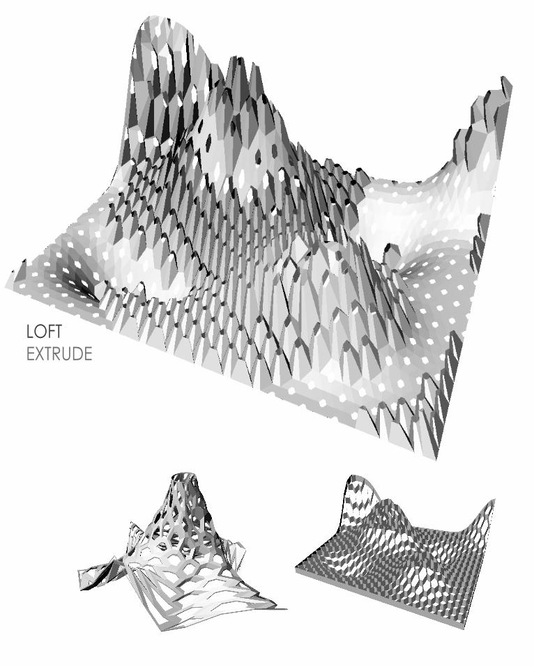
The image sampling task this week was based on the M. H de Young Museum in San Fransciso by Herzog and de Meuron. The pair punched and extruded a metal sheet with various patterns to create a textured metal surface. These were the principles used in the image samoking task. Two images were imported onto a surface and out-put as circles with smaller upward extrusions. The two circles could then be lofted to create the images above.
SURFACESURFACE DIVIDEPICTURE INPUT
EXPRESSIONEXPRESSIONZ PLANE
CIRCLECIRCLE
MOVE GRAFT
GRAFT] LOFT
U COUNT 100V COUNT 100
RADIUS 0.08VARIABLE Y 0.15EXP 1: (X x Y) + 0.1EXP 2: tan(y)x (x-0.1) in RADIANS @ 45 DEGREES
]x2

W E E K F I V ECASE STUDY 2.0 SHADOW PAVILION
The process of reverse engineering the [C]Space Pavilion was rather straight forward. Once the base curves were defined in rhino they had to be uniformely lofted to create the pavilion enclosure. After this the surface was divided into abritrary section that would then make up the fibre glass strips that are set at cross angles across the pavilion surface. The divisons were then made into isocurves across the surface and finally the curves were extruded at a ‘plane’ normal angle’ to origin to create the bending strip formation of the original pavilion.3
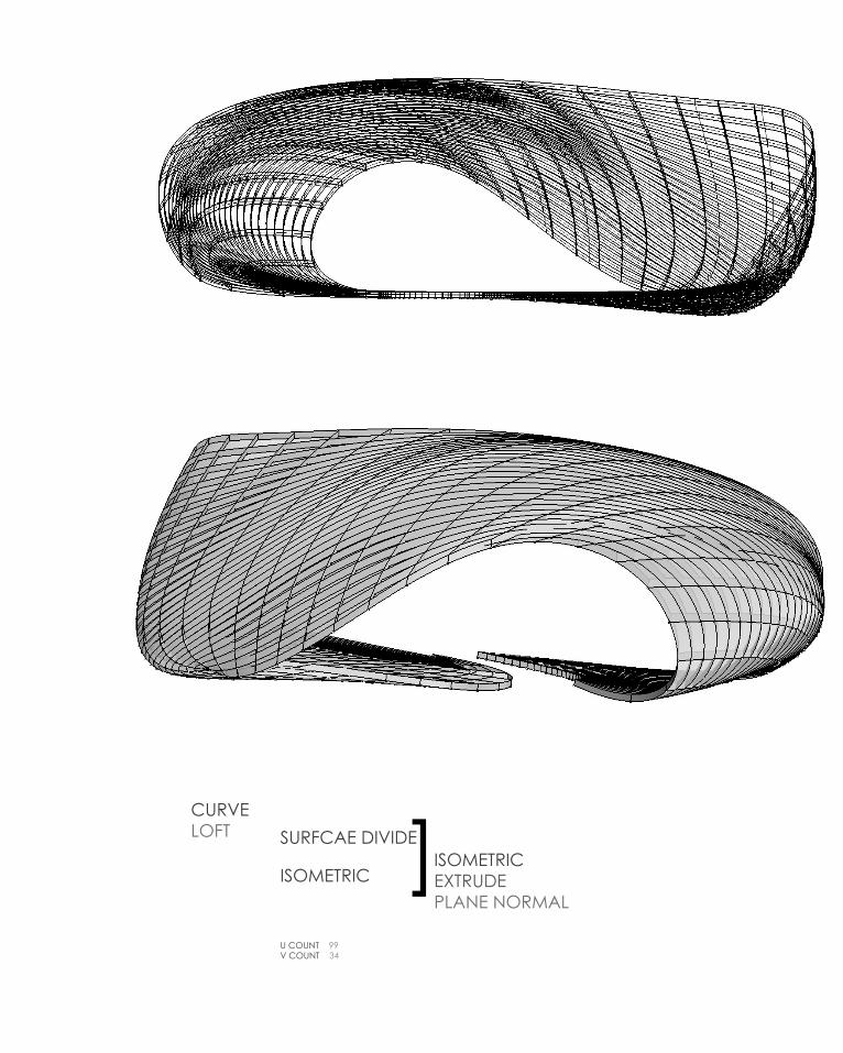
CURVELOFT SURFCAE DIVIDE
ISOMETRICISOMETRICEXTRUDEPLANE NORMAL
U COUNT 99V COUNT 34
]

W E E K F I V EC A S E S T U D Y 2 . 0 C O N E P A V I L I O N

CURVELOFT
SURFACE DIVIDE
DIVIDE
SURFACE DIVIDEDECONSTRUCT VECTOR
SURFACE BOX
BREPMESH MORPH
U COUNT 20U COUNT 20
U COUNT 20U COUNT 20
The Shadow Pavilion by Ply Architects was a self supporting structure created for the University of Michigan in Ann Arbor. The pavilion was based upon phyllotaxies, which is the natural formation pattern of layering of petals, nodules and leaves. The result was a geometric, circular dome type pavilion immersed in the soil. it was constructed out of lightweight strips of metal bent into connected open cones. The cones allow varying light and sounds into the space to create a sensory experience for the user.4

W E E K S I XCONTROLLING DATA STRUCTURES
SURFACESURFACE DIVIDE TREE STATISTICS
TAG
GRAFTSIMPLIFY
FLATTEN
This was a basic exercise to find out how to display input information by grafting and simplifying tree statistics
SURFACESURFACE DIVIDEMOVE TREE STATISTIC
TAG ITEM
SERIESZ PLANE
This task showed how to represent data in a grid and make this grid 3D. this system can be used to creae paths through data.
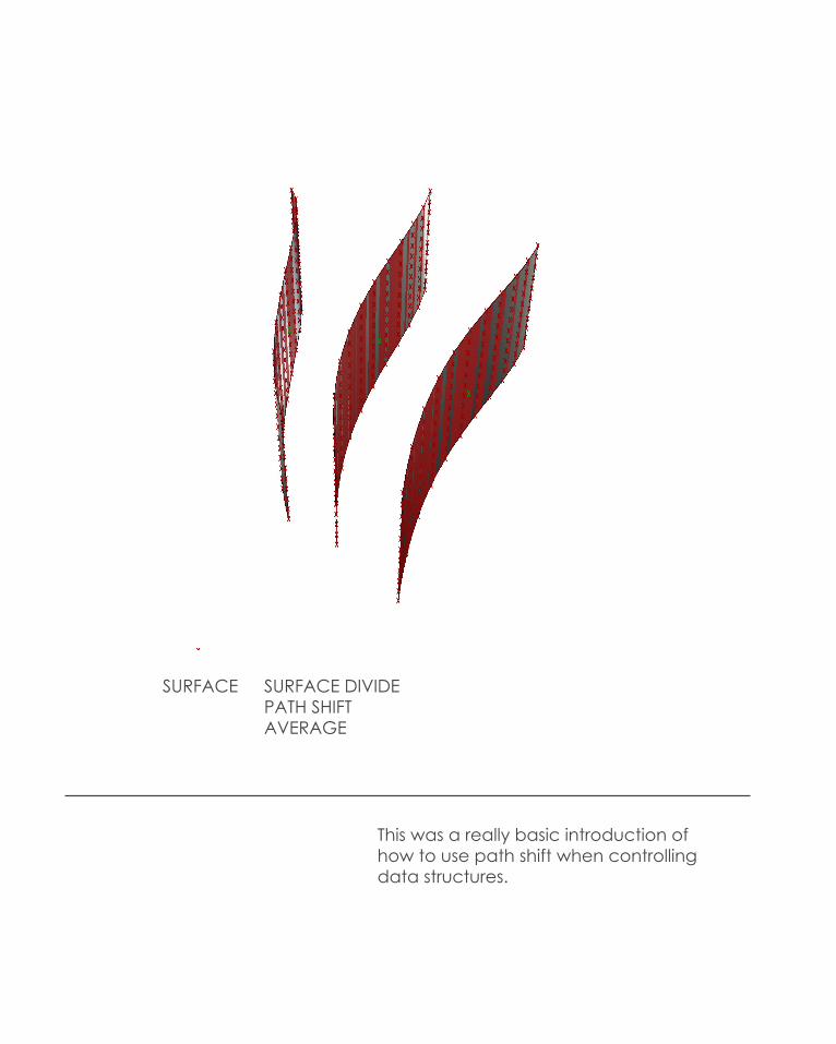
SURFACE SURFACE DIVIDEPATH SHIFTAVERAGE
This was a really basic introduction of how to use path shift when controlling data structures.

W E E K S I XT E C H N I Q U E D E V E L O P M E N T

The precedent we based this definition on was the Peace Bridge In Cal-gary, Canada again by Santiago Calatrava. The bridge as created to connect workers that travelled into the city daily for work. It required no piers and is cylindrical in form from bank to bank. 41
These iterations were interesting when we were able to change the base shape without the form becoming to far extracted and intersecting at chaotic angels. Where i could see the potential of this iteration going is to create a circular enclosure of thin tubes that could be covered in the thin photovoltaic cells. Finding a way of changing the base shape of the form was difficult and hindered our project. With further iterations the form stopped being aesthetically appealing and for that reason we decided not to progress to further development.5

W E E K S I XT E C H N I Q U E D E V E L O P M E N T


CURVELOFTSURFACE HEXAGON CELLS
ATTRACTOR WAVE CURVE SCALE
MOVE
INTEGER DIVISIONAMPLITUDE ]GRAFT
GRAFT LOFTEXTRUDE
U DIVISIONS 15V DIVISIONS 15
POINT ATTRACTOR
FACTOR 0.59
The result of creating a parametric definition based on the honeycomb project was quite successful in its variation from the original. The forms created were made by lofting and extruding hexagonal cells from a surface. By changing the parameters of the surface and the extrusion height we were able to create an interesting and var-ied set of forms that i think could have potential with the LAGI brief. When considering the solar technology we have chosen (thin film dye sensitized cells) it has potential as the extruded surfaces offer a lot of available surface area and the variation in ap-pearance could work well with changing cell colours.
W E E K S I XT E C H N I Q U E D E V E L O P M E N T
CURVELOFTSURFACE HEXAGON CELLS
ATTRACTOR WAVE CURVE SCALE
MOVE
INTEGER DIVISIONAMPLITUDE ]GRAFT
GRAFT LOFTEXTRUDE
U DIVISIONS 15V DIVISIONS 15
POINT ATTRACTOR
FACTOR 0.59
W E E K S I XT E C H N I Q U E D E V E L O P M E N T
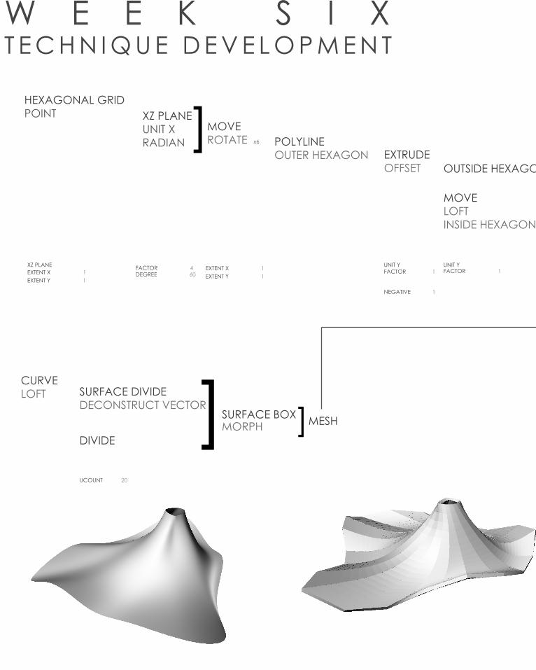
HEXAGONAL GRIDPOINT XZ PLANE
UNIT XRADIAN ]MOVE
ROTATE x6 POLYLINEOUTER HEXAGON EXTRUDE
OFFSET OUTSIDE HEXAGON
MOVELOFTINSIDE HEXAGON ]SOLID DIFFERENCE
BREP
MORPH
CURVELOFT SURFACE DIVIDE
DECONSTRUCT VECTOR
DIVIDE
SURFACE BOX MESH] ]
XZ PLANE UNIT Y
NEGATIVE 1
UNIT YEXTENT X 1EXTENT Y 1
EXTENT X 1FACTOR 4 FACTOR 1 FACTOR 1DEGREE 60
UCOUNT 20
UCOUNT 20
EXTENT Y 1
W E E K S I XT E C H N I Q U E D E V E L O P M E N T
HEXAGONAL GRIDPOINT XZ PLANE
UNIT XRADIAN ]MOVE
ROTATE x6 POLYLINEOUTER HEXAGON EXTRUDE
OFFSET OUTSIDE HEXAGON
MOVELOFTINSIDE HEXAGON ]SOLID DIFFERENCE
BREP
MORPH
CURVELOFT SURFACE DIVIDE
DECONSTRUCT VECTOR
DIVIDE
SURFACE BOX MESH] ]
XZ PLANE UNIT Y
NEGATIVE 1
UNIT YEXTENT X 1EXTENT Y 1
EXTENT X 1FACTOR 4 FACTOR 1 FACTOR 1DEGREE 60
UCOUNT 20
UCOUNT 20
EXTENT Y 1
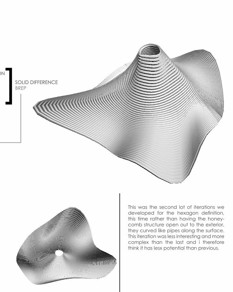
This was the second lot of iterations we developed for the hexagon definition, this time rather than having the honey-comb structure open out to the exterior, they curved like pipes along the surface. This iteration was less interesting and more complex than the last and i therefore think it has lesx potential than previous.
W E E K S I XT E C H N I Q U E D E V E L O P M E N T

W E E K S I XT E C H N I Q U E D E V E L O P M E N T
W E E K S I XT E C H N I Q U E D E V E L O P M E N T
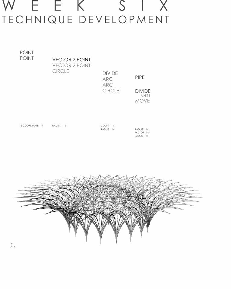
POINTPOINT VECTOR 2 POINT
VECTOR 2 POINTCIRCLE DIVIDE
ARC ARC CIRCLE DIVIDE
UNIT Z
MOVE
PIPE
Z COORDINATE 9RADUIS 16 RADUIS 16
FACTOR 0.5RADUIS 16
RADUIS 16 COUNT 6
W E E K S I XT E C H N I Q U E D E V E L O P M E N T
W E E K S I XT E C H N I Q U E D E V E L O P M E N T

DOMAINRANGE POINT
DIVISIONNEGATIVE
]]
CIRCLEMERGE
MERGE
DIVIDE] ]ROTATEFLIPINTERPOLATE
CURVELOFT
PROJECTEXTRUDE AREA
EXTRUDESURFACE FRAMES CULL
FLATTENCULL
DOMAIN END 0DOMAIN END 0
DATA 2 100 UNIT ZNUMBER SLIDER 1.28
NUMBER SLIDER 1NUMBER SLIDER 1DATA 3 18
B VALUE 31
B VALUE 31A VALUE 654
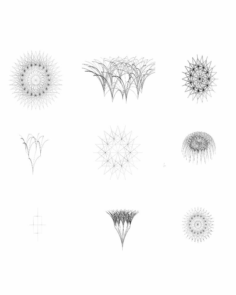
These two pavilion definitions were not created with a precedent in mind, rather they are a free form result from experimenting with grasshopper pa-rameters. I feel that these two prior iteration definitions have limited potential with the LAGI brief. This second iteration has potential as a covering pavilion structure and the first serves well as a space to be in, however I don’t think they are visually interesting enough. The first definition created i find to be too busy overall as well as being too analogous with the form of a sunflower, i feel that the users would take that visual away rather than the point of the entry which is to engage and create renewable energy. Where the first defi-nition is too busy, the second is to simple in design and does not allow for much parametric manipulation.
W E E K S I XT E C H N I Q U E D E V E L O P M E N T
DOMAINRANGE POINT
DIVISIONNEGATIVE
]]
CIRCLEMERGE
MERGE
DIVIDE] ]ROTATEFLIPINTERPOLATE
CURVELOFT
PROJECTEXTRUDE AREA
EXTRUDESURFACE FRAMES CULL
FLATTENCULL
DOMAIN END 0DOMAIN END 0
DATA 2 100 UNIT ZNUMBER SLIDER 1.28
NUMBER SLIDER 1NUMBER SLIDER 1DATA 3 18
B VALUE 31
B VALUE 31A VALUE 654
W E E K S I XT E C H N I Q U E D E V E L O P M E N T
A x BSINE
RADIANRADIAN
DOMAIN] x 6
REMAP x 6
A + B x 4
A - B x 2]
POINT ] x 4
] ]YZ PLANEMERGE
MERGELOFT
POLYLINEOFFSET
END POINTSLINELINE
SHIFT PATHS
END POINTS
-1 to 1
DISTANCE 83STEPS 368
DEGREES 80DEGREES 100DEGREES 100DEGREES 30
B VALUE 60 B VALUE 2.4B VALUE 3.6B VALUE 2.75B VALUE 2.6B VALUE 2.5B VALUE 4.1
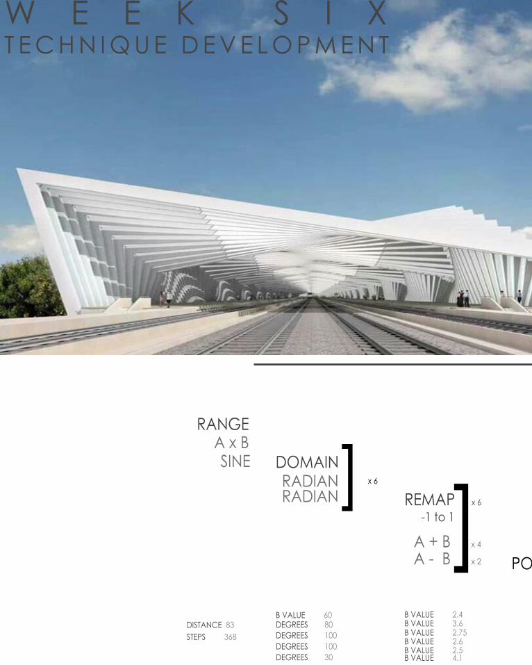
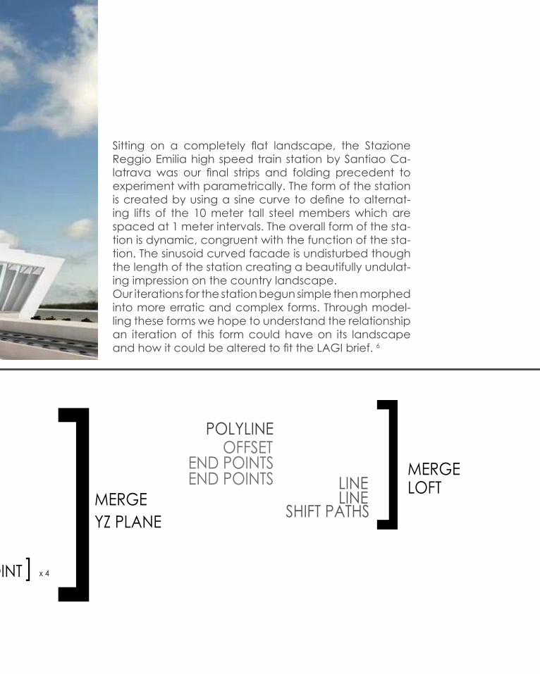
Sitting on a completely flat landscape, the Stazione Reggio Emilia high speed train station by Santiao Ca-latrava was our final strips and folding precedent to experiment with parametrically. The form of the station is created by using a sine curve to define to alternat-ing lifts of the 10 meter tall steel members which are spaced at 1 meter intervals. The overall form of the sta-tion is dynamic, congruent with the function of the sta-tion. The sinusoid curved facade is undisturbed though the length of the station creating a beautifully undulat-ing impression on the country landscape.Our iterations for the station begun simple then morphed into more erratic and complex forms. Through model-ling these forms we hope to understand the relationship an iteration of this form could have on its landscape and how it could be altered to fit the LAGI brief. 6
W E E K S I XT E C H N I Q U E D E V E L O P M E N T

W E E K S I XT E C H N I Q U E D E V E L O P M E N T

W E E K S I XT E C H N I Q U E D E V E L O P M E N T
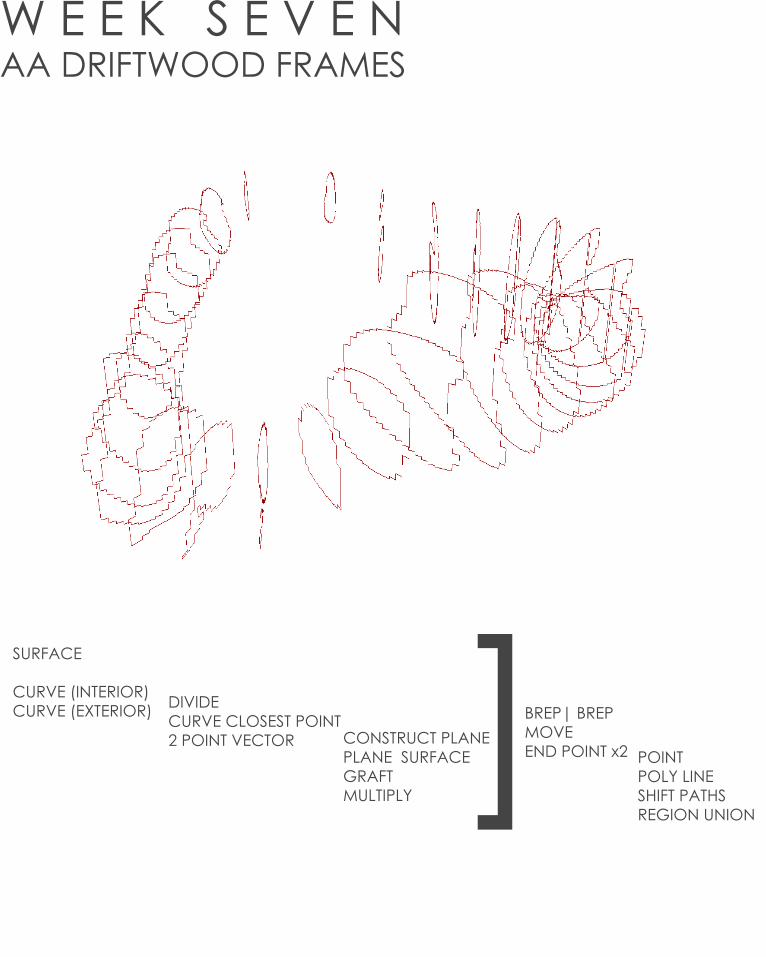
W E E K S E V E NAA DRIFTWOOD FRAMES
SURFACE
CURVE (INTERIOR)CURVE (EXTERIOR) DIVIDE
CURVE CLOSEST POINT2 POINT VECTOR CONSTRUCT PLANE
PLANE SURFACEGRAFTMULTIPLY
POINTPOLY LINESHIFT PATHSREGION UNION
]BREP| BREPMOVEEND POINT x2
POINTPOLY LINESHIFT PATHSREGION UNION
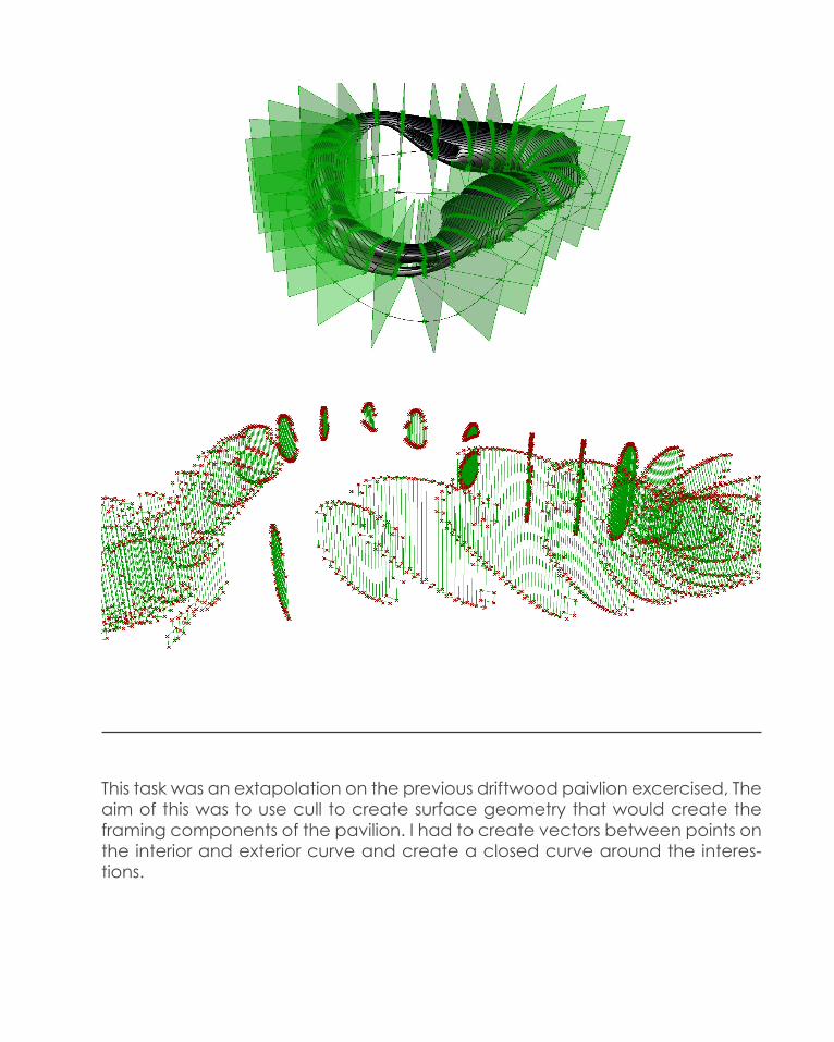
This task was an extapolation on the previous driftwood paivlion excercised, The aim of this was to use cull to create surface geometry that would create the framing components of the pavilion. I had to create vectors between points on the interior and exterior curve and create a closed curve around the interes-tions.
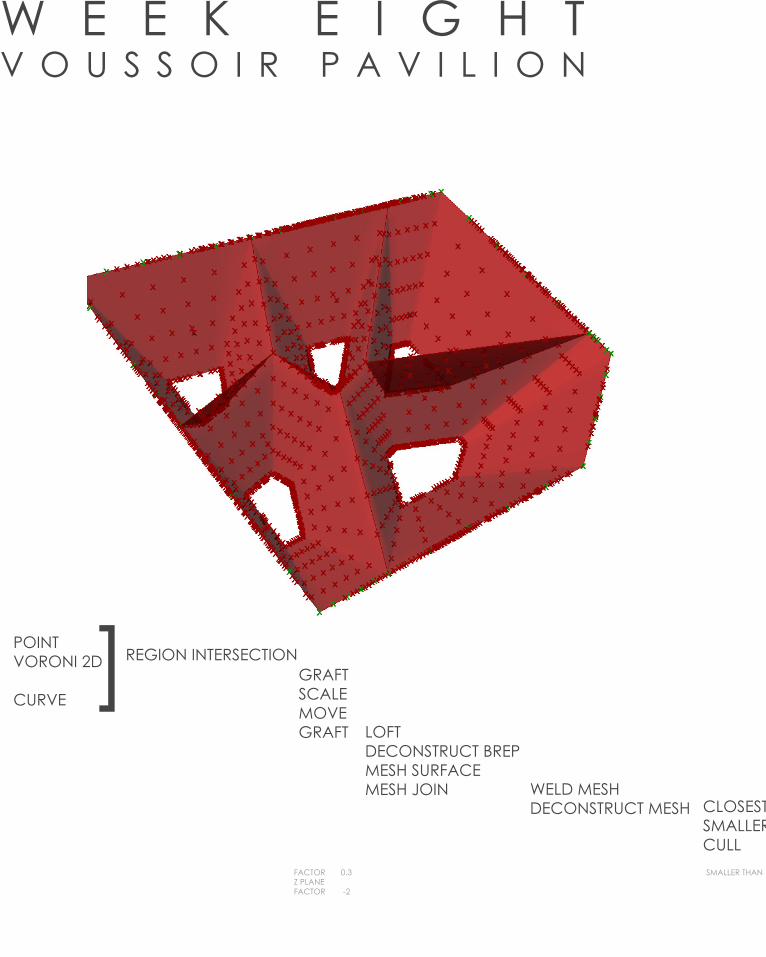
W E E K E I G H TV O U S S O I R P A V I L I O N
REGION INTERSECTIONGRAFTSCALEMOVEGRAFT LOFT
DECONSTRUCT BREPMESH SURFACEMESH JOIN WELD MESH
DECONSTRUCT MESH CLOSEST POINTSMALLER THANCULL
POINTVORONI 2D
CURVE]
FACTOR 0.3Z PLANEFACTOR -2
SMALLER THAN 0.02

CLOSEST POINTSMALLER THANCULL ]X2
SMALLER THAN 0.02
This video was the introduction to reverse engineering the voussoir cloud pa-vilion by Iwamoto Scott. The pavilion is a series of arch ways with flat vo-roni patternings. The first part of the video was demonstrating how to input a quad mesh onto the vaults.

F I N A L F O R M
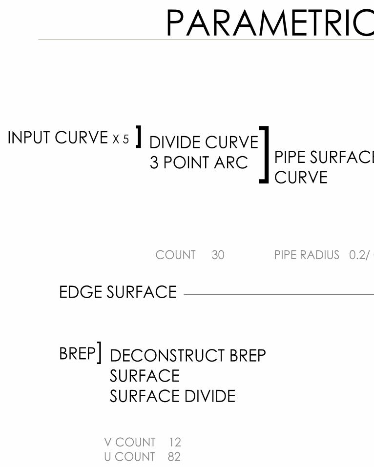
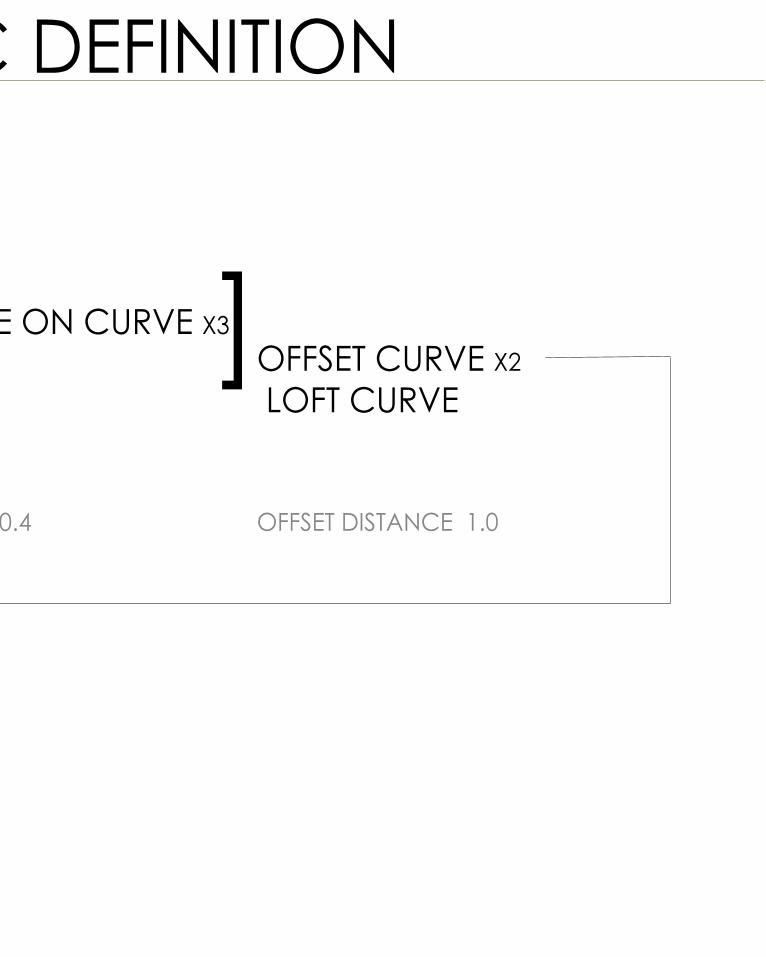
PARAMETRIC DEFINITION
INPUT CURVE X 5 ]
] ]PIPE SURFACE ON CURVE X3CURVE OFFSET CURVE X2
LOFT CURVE
EDGE SURFACE
DIVIDE CURVE 3 POINT ARC
BREP] DECONSTRUCT BREPSURFACESURFACE DIVIDE
COUNT 30 PIPE RADIUS 0.2/ 0.4 OFFSET DISTANCE 1.0
V COUNT 12U COUNT 82
PARAMETRIC DEFINITION
INPUT CURVE X 5 ]
] ]PIPE SURFACE ON CURVE X3CURVE OFFSET CURVE X2
LOFT CURVE
EDGE SURFACE
DIVIDE CURVE 3 POINT ARC
BREP] DECONSTRUCT BREPSURFACESURFACE DIVIDE
COUNT 30 PIPE RADIUS 0.2/ 0.4 OFFSET DISTANCE 1.0
V COUNT 12U COUNT 82
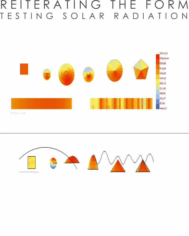
R E I T E R A T I N G T H E F O R MT E S T I N G S O L A R R A D I A T I O N
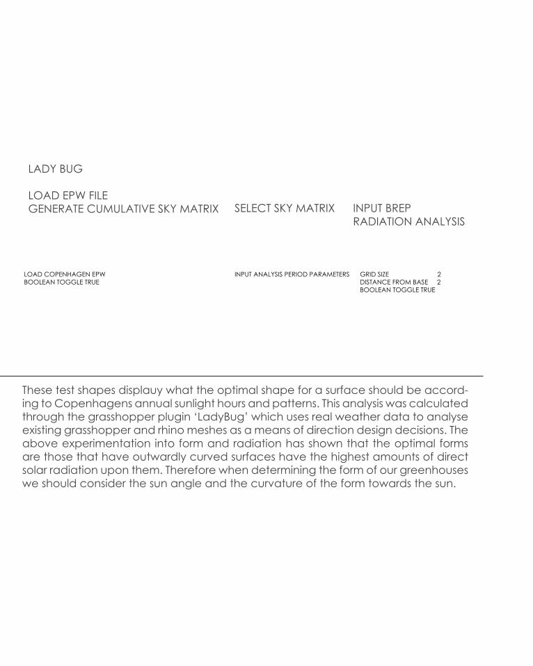
These test shapes displauy what the optimal shape for a surface should be accord-ing to Copenhagens annual sunlight hours and patterns. This analysis was calculated through the grasshopper plugin ‘LadyBug’ which uses real weather data to analyse existing grasshopper and rhino meshes as a means of direction design decisions. The above experimentation into form and radiation has shown that the optimal forms are those that have outwardly curved surfaces have the highest amounts of direct solar radiation upon them. Therefore when determining the form of our greenhouses we should consider the sun angle and the curvature of the form towards the sun.
LADY BUG
LOAD EPW FILEGENERATE CUMULATIVE SKY MATRIX SELECT SKY MATRIX INPUT BREP
RADIATION ANALYSIS
LOAD COPENHAGEN EPWBOOLEAN TOGGLE TRUE
INPUT ANALYSIS PERIOD PARAMETERS GRID SIZE 2DISTANCE FROM BASE 2BOOLEAN TOGGLE TRUE

R E I T E R A T I N G T H E F O R MT E S T I N G S O L A R R A D I A T I O N
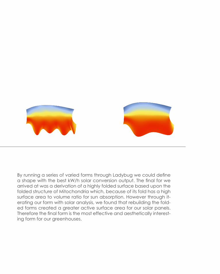
By running a series of varied forms through Ladybug we could define a shape with the best kW/h solar conversion output. The final for we arrived at was a derivation of a highly folded surface based upon the folded structure of Mitochondria which, because of its fold has a high surface area to volume ratio for sun absorption. However through it-erating our form with solar analysis, we found that rebuilding the fold-ed forms created a greater active surface area for our solar panels. Therefore the final form is the most effective and aesthetically interest-ing form for our greenhouses.

REFERENCES
1. umacher, P 2009, ‘Parametric Patterns: Patterns of Architecture’, AD Architectural Design, Vol. 79, No. 6, Nov/ Dec 2009
2. Repository of Computation Design, Biothing: Seroussi Palilion, 2010, last viewed April 2, http://www.biothing.org/?cat=5
3. [C]Space Pavilion by Alan Dempsey and Alvin Huang, DeZeen Magazine, last viewed April 9, http://www.dezeen.com/2007/11/04/cspace-pavilion-by-alan-dempsey-and-alvin-huang/
4. Andrew Michler, Shadow Pavilion Informed by Biomimicry, 2011, last viewed April 9, http://www.evolo.us/architecture/shadow-pavil-ion-informed-by-biomimicry-ply-architecture/
5. DesignBoom, Top Ten Public Spaces, 2010, last viewed April 26, http://www.designboom.com/architecture/designboom-2012-top-ten-public-spaces/
6. Architectural Detail, (2012), Perfect Wave: The New High Speed Railway Station in Italy, Last viewed April 3, http://www.detail-online.com/architecture/topics/the-perfect-wave-new-high-speed-train-station-in-italy-021674.html