Embed Size (px)
Citation preview

Air Sequencer
ECE 3872-B Group 2A
Stefan Abi-Karam Leonid Pozdneev Divyam Mishra
Ethan Taylor
Date: November 06, 2020
1
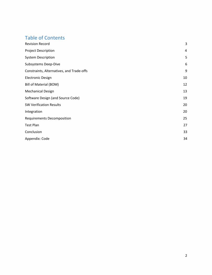
Table of Contents Revision Record 3 Project Description 4
System Description 5
Subsystems Deep-Dive 6
Constraints, Alternatives, and Trade-offs 9
Electronic Design 10
Bill of Material (BOM) 12
Mechanical Design 13
Software Design (and Source Code) 19
SW Verification Results 20
Integration 20
Requirements Decomposition 25
Test Plan 27
Conclusion 33
Appendix: Code 34
2
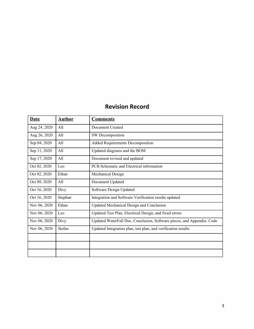
Revision Record
3
Date Author Comments Aug 24, 2020 All Document Created
Aug 26, 2020 All SW Decomposition
Sep 04, 2020 All Added Requirements Decomposition
Sep 11, 2020 All Updated diagrams and the BOM
Sep 17, 2020 All Document revised and updated
Oct 02, 2020 Leo PCB Schematic and Electrical information
Oct 02, 2020 Ethan Mechanical Design
Oct 09, 2020 All Document Updated
Oct 16, 2020 Divy Software Design Updated
Oct 16, 2020 Stephan Integration and Software Verification results updated
Nov 06, 2020 Ethan Updated Mechanical Design and Conclusion
Nov 06, 2020 Leo Updated Test Plan, Electrical Design, and fixed errors
Nov 06, 2020 Divy Updated WaterFall Doc, Conclusion, Software pieces, and Appendix: Code
Nov 06, 2020 Stefan Updated Integration plan, test plan, and verification results
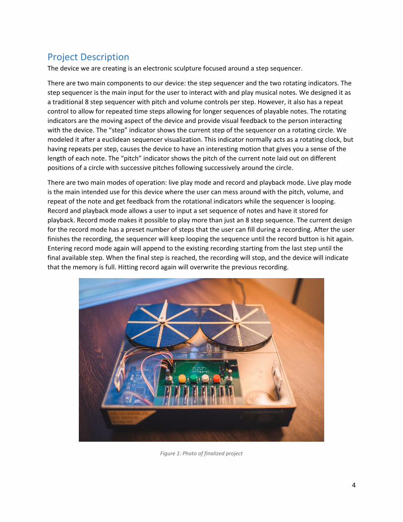
Project Description The device we are creating is an electronic sculpture focused around a step sequencer.
There are two main components to our device: the step sequencer and the two rotating indicators. The step sequencer is the main input for the user to interact with and play musical notes. We designed it as a traditional 8 step sequencer with pitch and volume controls per step. However, it also has a repeat control to allow for repeated time steps allowing for longer sequences of playable notes. The rotating indicators are the moving aspect of the device and provide visual feedback to the person interacting with the device. The “step” indicator shows the current step of the sequencer on a rotating circle. We modeled it after a euclidean sequencer visualization. This indicator normally acts as a rotating clock, but having repeats per step, causes the device to have an interesting motion that gives you a sense of the length of each note. The “pitch” indicator shows the pitch of the current note laid out on different positions of a circle with successive pitches following successively around the circle.
There are two main modes of operation: live play mode and record and playback mode. Live play mode is the main intended use for this device where the user can mess around with the pitch, volume, and repeat of the note and get feedback from the rotational indicators while the sequencer is looping. Record and playback mode allows a user to input a set sequence of notes and have it stored for playback. Record mode makes it possible to play more than just an 8 step sequence. The current design for the record mode has a preset number of steps that the user can fill during a recording. After the user finishes the recording, the sequencer will keep looping the sequence until the record button is hit again. Entering record mode again will append to the existing recording starting from the last step until the final available step. When the final step is reached, the recording will stop, and the device will indicate that the memory is full. Hitting record again will overwrite the previous recording.
Figure 1: Photo of finalized project
4
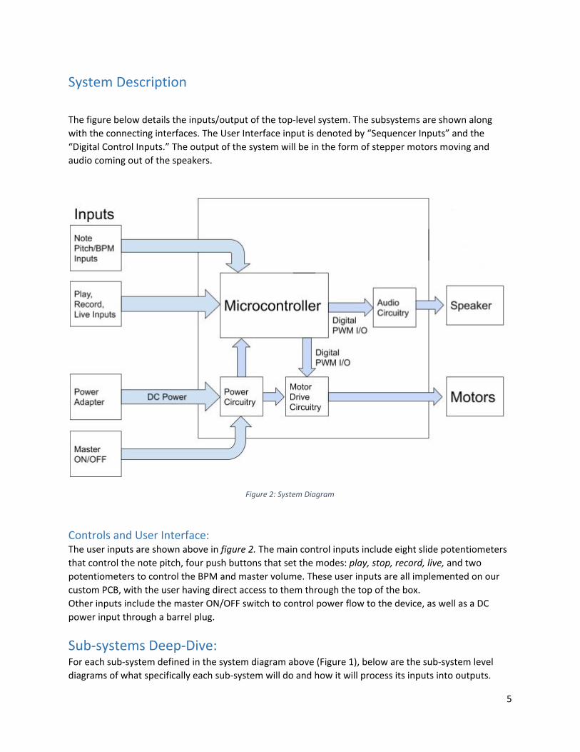
System Description
The figure below details the inputs/output of the top-level system. The subsystems are shown along with the connecting interfaces. The User Interface input is denoted by “Sequencer Inputs” and the “Digital Control Inputs.” The output of the system will be in the form of stepper motors moving and audio coming out of the speakers.
Figure 2: System Diagram
Controls and User Interface: The user inputs are shown above in figure 2. The main control inputs include eight slide potentiometers that control the note pitch, four push buttons that set the modes: play, stop, record, live, and two potentiometers to control the BPM and master volume. These user inputs are all implemented on our custom PCB, with the user having direct access to them through the top of the box. Other inputs include the master ON/OFF switch to control power flow to the device, as well as a DC power input through a barrel plug.
Sub-systems Deep-Dive: For each sub-system defined in the system diagram above (Figure 1), below are the sub-system level diagrams of what specifically each sub-system will do and how it will process its inputs into outputs.
5
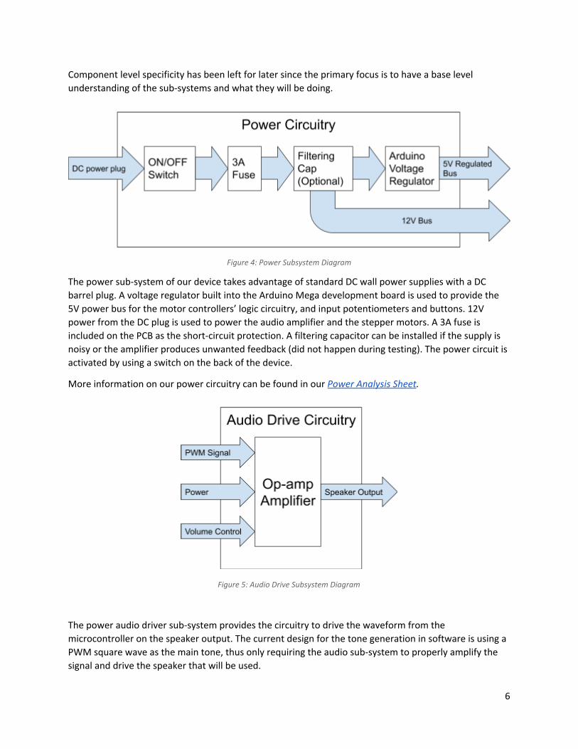
Component level specificity has been left for later since the primary focus is to have a base level understanding of the sub-systems and what they will be doing.
Figure 4: Power Subsystem Diagram
The power sub-system of our device takes advantage of standard DC wall power supplies with a DC barrel plug. A voltage regulator built into the Arduino Mega development board is used to provide the 5V power bus for the motor controllers’ logic circuitry, and input potentiometers and buttons. 12V power from the DC plug is used to power the audio amplifier and the stepper motors. A 3A fuse is included on the PCB as the short-circuit protection. A filtering capacitor can be installed if the supply is noisy or the amplifier produces unwanted feedback (did not happen during testing). The power circuit is activated by using a switch on the back of the device.
More information on our power circuitry can be found in our Power Analysis Sheet.
Figure 5: Audio Drive Subsystem Diagram
The power audio driver sub-system provides the circuitry to drive the waveform from the microcontroller on the speaker output. The current design for the tone generation in software is using a PWM square wave as the main tone, thus only requiring the audio sub-system to properly amplify the signal and drive the speaker that will be used.
6
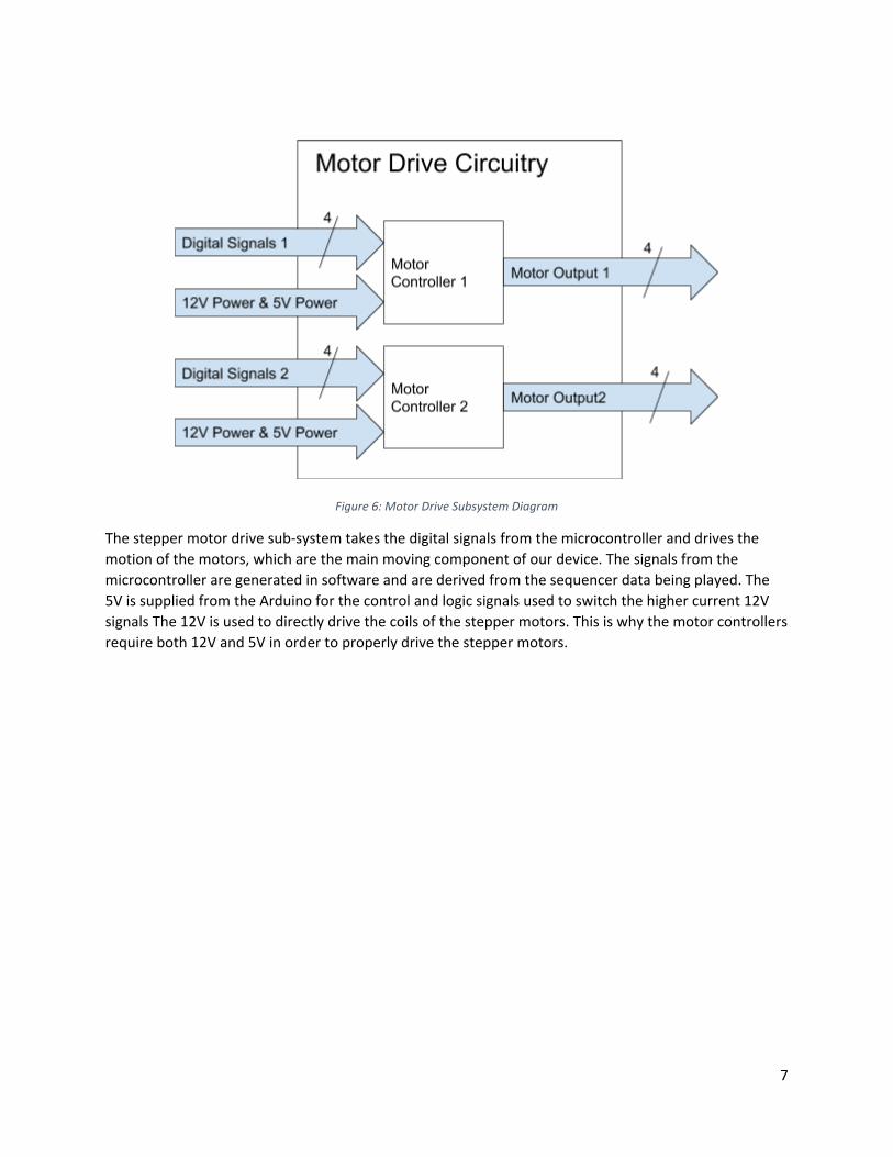
Figure 6: Motor Drive Subsystem Diagram
The stepper motor drive sub-system takes the digital signals from the microcontroller and drives the motion of the motors, which are the main moving component of our device. The signals from the microcontroller are generated in software and are derived from the sequencer data being played. The 5V is supplied from the Arduino for the control and logic signals used to switch the higher current 12V signals The 12V is used to directly drive the coils of the stepper motors. This is why the motor controllers require both 12V and 5V in order to properly drive the stepper motors.
7
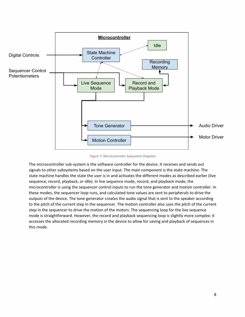
Figure 7: Microcontroller Subsystem Diagram
The microcontroller sub-system is the software controller for the device. It receives and sends out signals to other subsystems based on the user input. The main component is the state machine. The state machine handles the state the user is in and activates the different modes as described earlier (live sequence, record, playback, or idle). In live sequence mode, record, and playback mode, the microcontroller is using the sequencer control inputs to run the tone generator and motion controller. In these modes, the sequencer loop runs, and calculated tone values are sent to peripherals to drive the outputs of the device. The tone generator creates the audio signal that is sent to the speaker according to the pitch of the current step in the sequencer. The motion controller also uses the pitch of the current step in the sequencer to drive the motion of the motors. The sequencing loop for the live sequence mode is straightforward. However, the record and playback sequencing loop is slightly more complex: it accesses the allocated recording memory in the device to allow for saving and playback of sequences in this mode.
8
Constraints, Alternatives, and Trade-offs The following design alternatives have been considered:
● Volume control for each sequencer slider. ○ Pros: this will allow the user to create more complex melodic structures. ○ Cons: more analog inputs will require a use of an external ADC and will increase the cost
of the device. ○ Decision: we did not choose to add volume controls to each individual input due to the
increase in complexity of electronic design and higher cost. Considering time constraints and limited availability of the manufacturing space, this detail would be an unnecessary risk.
● LED indicators for each sequencer step. ○ Pros: will make it easier for the user to know which note is currently playing. ○ Cons: more digital outputs required from the microcontroller, more complexity in
software and wiring. ○ Decision: we chose to not include LED indicators in the final design to simplify wiring
and software. ● Stepper motors vs. servos.
○ Servos: require less inputs and are easier to control, but could be hard to find servos that are fast enough to meet the timing requirement of 0.5 s per note.
○ Stepper motors: require more inputs to drive which will require two controllers instead of one, leading to a higher cost; however, it is easier to spec stepper motors that will meet the timing requirement when run at 12 V.
○ Decision: we decide to go with the stepper motor option due to concerns with meeting timing requirements. A potential failure with servos would cause a significant setback, so we concluded that the added cost of stepper motors and motor controllers was justified by the guarantee of a working design.
9
Electronic Design
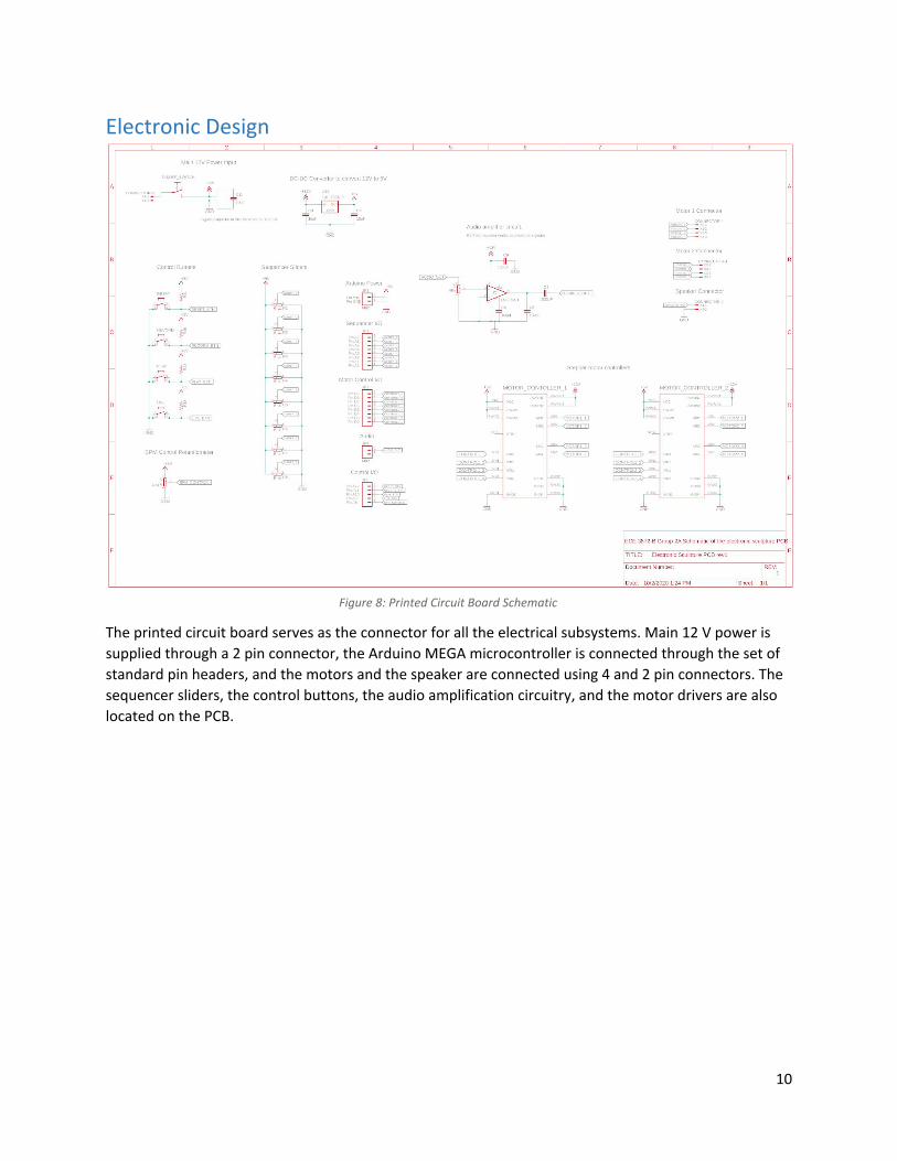
Figure 8: Printed Circuit Board Schematic
The printed circuit board serves as the connector for all the electrical subsystems. Main 12 V power is supplied through a 2 pin connector, the Arduino MEGA microcontroller is connected through the set of standard pin headers, and the motors and the speaker are connected using 4 and 2 pin connectors. The sequencer sliders, the control buttons, the audio amplification circuitry, and the motor drivers are also located on the PCB.
10
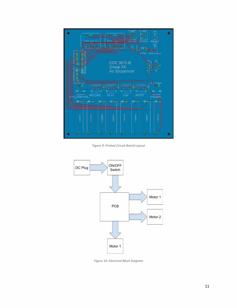
Figure 9: Printed Circuit Board Layout
Figure 10: Electrical Block Diagram
11
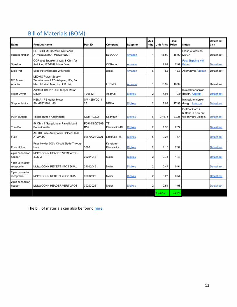
Bill of Materials (BOM)
The bill of materials can also be found here.
12
Name Product Name Part ID Company Supplier Quantity Unit Price
Total Price Notes
Datasheet Link
Microcontroller ELEGOO MEGA 2560 R3 Board ATmega2560 ATMEGA16U2 ELEGOO Amazon 1 15.99 15.99
Clone of Arduino MEGA Datasheet
Speaker CQRobot Speaker 3 Watt 8 Ohm for Arduino, JST-PH2.0 Interface. CQRobot Amazon 1 7.99 7.99
Fast Shipping with Prime. Datasheet
Slide Pot Slide Potentiometer with Knob uxcell Amazon 8 1.6 12.8 Alternative: Adafruit Datasheet
DC Power Adaptor
LEDMO Power Supply, Transformers,LED Adapter, 12V, 5A Max, 60 Watt Max, for LED Strip LEDMO Amazon 1 10.99 10.99 Datasheet
Motor Driver Adafruit TB6612 DC/Stepper Motor Driver TB6612 Adafruit Digikey 2 4.95 9.9
In stock for senior design. Adafruit Datasheet
Stepper Motor NEMA 17 Stepper Motor SM-42BYG011-25
SM-42BYG011-25 NEMA Digikey 2 8.99 17.98
In stock for senior design. Amazon Datasheet
Push Buttons Tactile Button Assortment COM-10302 Sparkfun Digikey 6 0.4875 2.925
Full Pack of 12 buttons is 5.85 but we only are using 6 Datasheet
Turn Pot 5k Ohm 1 Gang Linear Panel Mount Potentiometer
P0915N-QC20BR5K
TT Electronics/BI Digikey 2 1.36 2.72 Datasheet
Fuse AC DC Fuse Automotive Holder Blade, ATO/ATC 0287002.PXCN Littelfuse Inc. Digikey 5 0.28 1.4 Datasheet
Fuse Holder Fuse Holder 500V Circuit Blade Through Hole 3568
Keystone Electronics Digikey 2 1.16 2.32 Datasheet
4 pin connector header
Molex CONN HEADER VERT 4POS 4.2MM 39281043 Molex Digikey 2 0.74 1.48 Datasheet
4 pin connector receptacle Molex CONN RECEPT 4POS DUAL 39012045 Molex Digikey 2 0.47 0.94 Datasheet
2 pin connector receptacle Molex CONN RECEPT 2POS DUAL 39012020 Molex Digikey 2 0.27 0.54 Datasheet
2 pin connector header Molex CONN HEADER VERT 2POS 39293026 Molex Digikey 2 0.54 1.08 Datasheet
Total Cost: 89.055
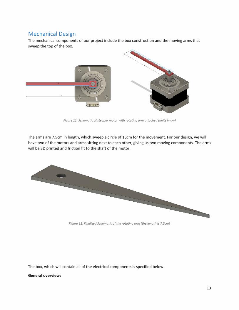
Mechanical Design The mechanical components of our project include the box construction and the moving arms that sweep the top of the box.
Figure 11: Schematic of stepper motor with rotating arm attached (units in cm)
The arms are 7.5cm in length, which sweep a circle of 15cm for the movement. For our design, we will have two of the motors and arms sitting next to each other, giving us two moving components. The arms will be 3D printed and friction fit to the shaft of the motor.
Figure 12: Finalized Schematic of the rotating arm (the length is 7.5cm)
The box, which will contain all of the electrical components is specified below.
General overview:
13
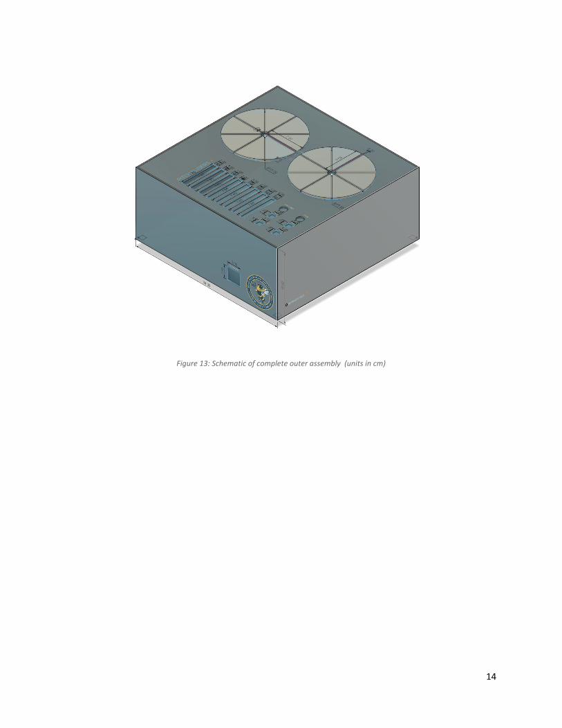
Figure 13: Schematic of complete outer assembly (units in cm)
14
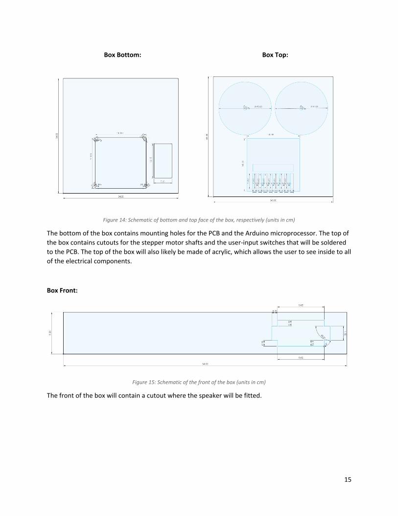
Figure 14: Schematic of bottom and top face of the box, respectively (units in cm)
The bottom of the box contains mounting holes for the PCB and the Arduino microprocessor. The top of the box contains cutouts for the stepper motor shafts and the user-input switches that will be soldered to the PCB. The top of the box will also likely be made of acrylic, which allows the user to see inside to all of the electrical components.
Box Front:
Figure 15: Schematic of the front of the box (units in cm)
The front of the box will contain a cutout where the speaker will be fitted.
15
Box Bottom: Box Top:
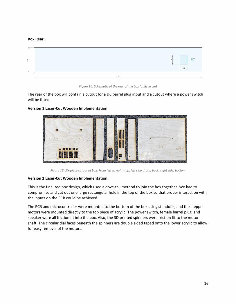
Box Rear:
Figure 16: Schematic of the rear of the box (units in cm)
The rear of the box will contain a cutout for a DC barrel plug input and a cutout where a power switch will be fitted.
Version 1 Laser-Cut Wooden Implementation:
Figure 16: Six-piece cutout of box. From left to right: top, left side, front, back, right side, bottom
Version 2 Laser-Cut Wooden Implementation:
This is the finalized box design, which used a dove-tail method to join the box together. We had to compromise and cut out one large rectangular hole in the top of the box so that proper interaction with the inputs on the PCB could be achieved.
The PCB and microcontroller were mounted to the bottom of the box using standoffs, and the stepper motors were mounted directly to the top piece of acrylic. The power switch, female barrel plug, and speaker were all friction fit into the box. Also, the 3D printed spinners were friction fit to the motor shaft. The circular dial faces beneath the spinners are double sided taped onto the lower acrylic to allow for easy removal of the motors.
16
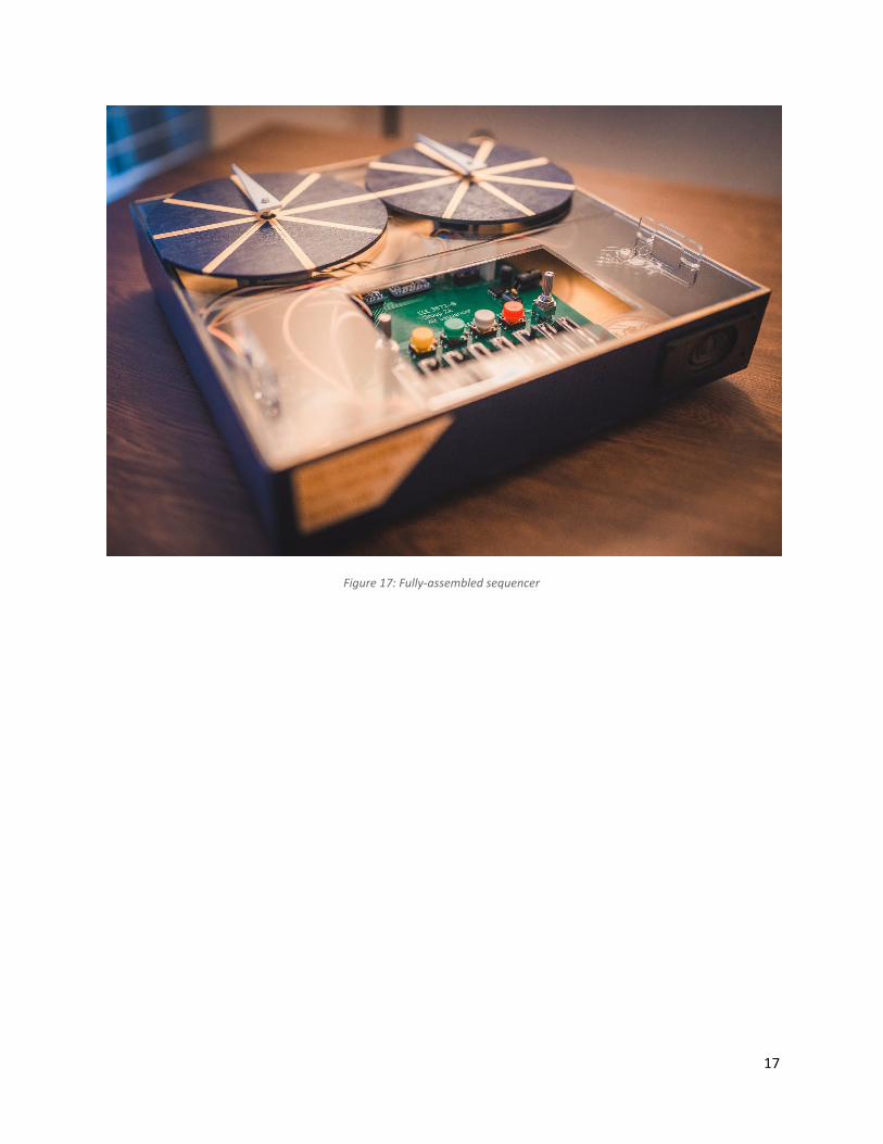
Figure 17: Fully-assembled sequencer
17
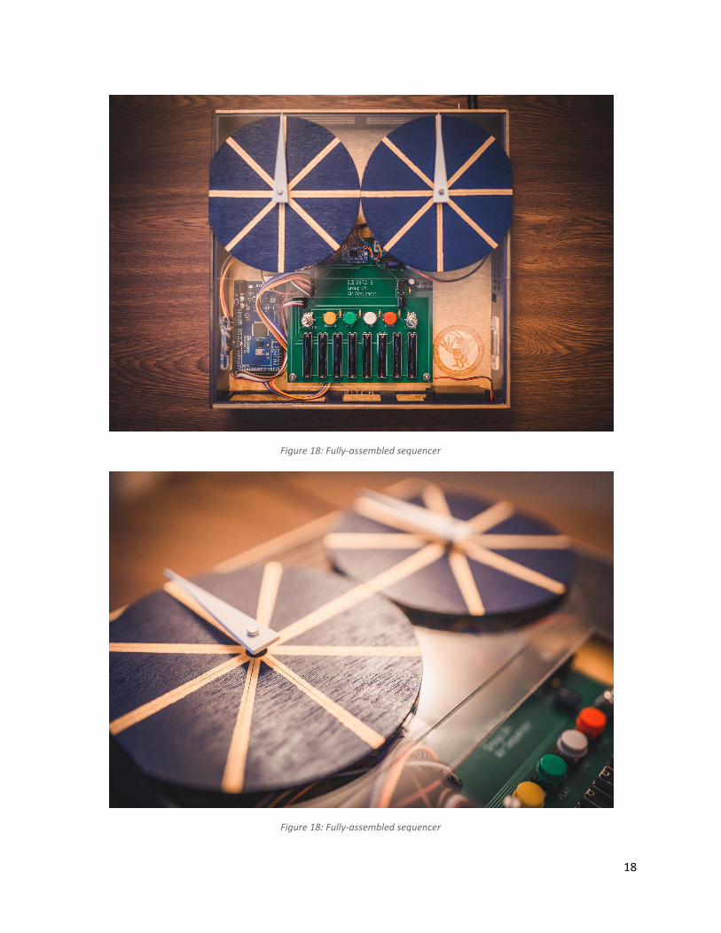
Figure 18: Fully-assembled sequencer
Figure 18: Fully-assembled sequencer
18
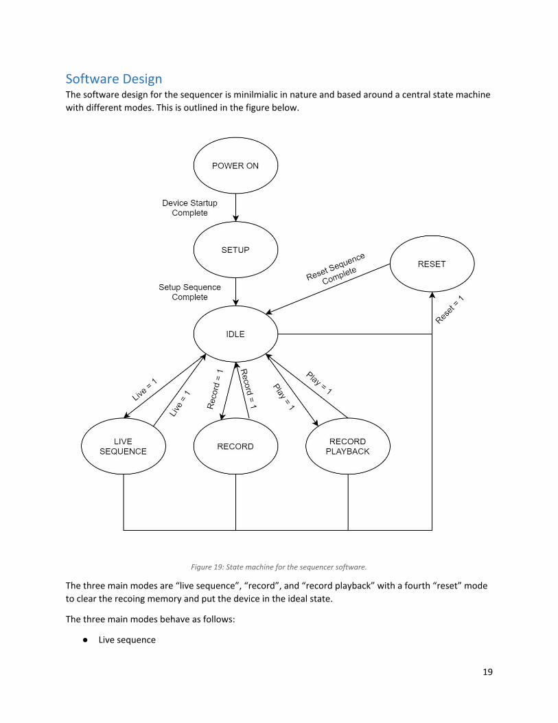
Software Design The software design for the sequencer is minilmialic in nature and based around a central state machine with different modes. This is outlined in the figure below.
Figure 19: State machine for the sequencer software.
The three main modes are “live sequence”, “record”, and “record playback” with a fourth “reset” mode to clear the recoing memory and put the device in the ideal state.
The three main modes behave as follows:
● Live sequence
19
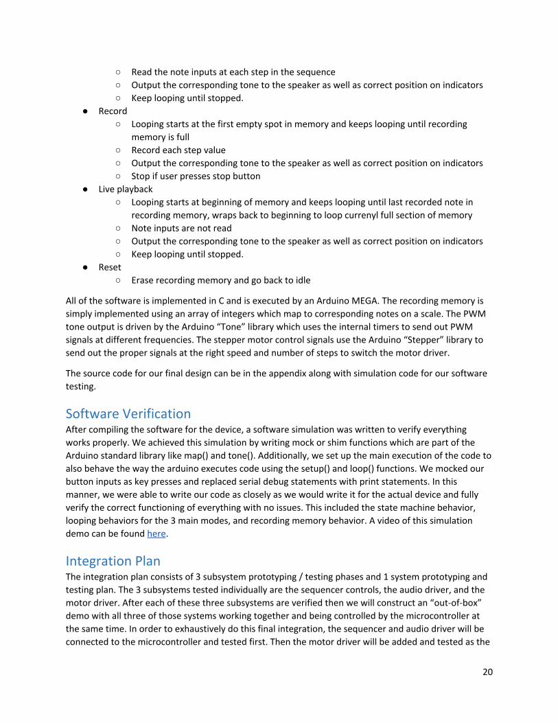
○ Read the note inputs at each step in the sequence ○ Output the corresponding tone to the speaker as well as correct position on indicators ○ Keep looping until stopped.
● Record ○ Looping starts at the first empty spot in memory and keeps looping until recording
memory is full ○ Record each step value ○ Output the corresponding tone to the speaker as well as correct position on indicators ○ Stop if user presses stop button
● Live playback ○ Looping starts at beginning of memory and keeps looping until last recorded note in
recording memory, wraps back to beginning to loop currenyl full section of memory ○ Note inputs are not read ○ Output the corresponding tone to the speaker as well as correct position on indicators ○ Keep looping until stopped.
● Reset ○ Erase recording memory and go back to idle
All of the software is implemented in C and is executed by an Arduino MEGA. The recording memory is simply implemented using an array of integers which map to corresponding notes on a scale. The PWM tone output is driven by the Arduino “Tone” library which uses the internal timers to send out PWM signals at different frequencies. The stepper motor control signals use the Arduino “Stepper” library to send out the proper signals at the right speed and number of steps to switch the motor driver.
The source code for our final design can be in the appendix along with simulation code for our software testing.
Software Verification After compiling the software for the device, a software simulation was written to verify everything works properly. We achieved this simulation by writing mock or shim functions which are part of the Arduino standard library like map() and tone(). Additionally, we set up the main execution of the code to also behave the way the arduino executes code using the setup() and loop() functions. We mocked our button inputs as key presses and replaced serial debug statements with print statements. In this manner, we were able to write our code as closely as we would write it for the actual device and fully verify the correct functioning of everything with no issues. This included the state machine behavior, looping behaviors for the 3 main modes, and recording memory behavior. A video of this simulation demo can be found here.
Integration Plan The integration plan consists of 3 subsystem prototyping / testing phases and 1 system prototyping and testing plan. The 3 subsystems tested individually are the sequencer controls, the audio driver, and the motor driver. After each of these three subsystems are verified then we will construct an “out-of-box” demo with all three of those systems working together and being controlled by the microcontroller at the same time. In order to exhaustively do this final integration, the sequencer and audio driver will be connected to the microcontroller and tested first. Then the motor driver will be added and tested as the
20
last step of the full integration. This lets us simplify the interaction between subsystems if any issues were to arise and debugging was required. More details from currently tested subsystems are included in the following subsections.
Addially, in order to carry out this integration in a timely manner we have outlined a schule in the coming 3 weeks to achieve this as a team. That schedule can be found at this link.
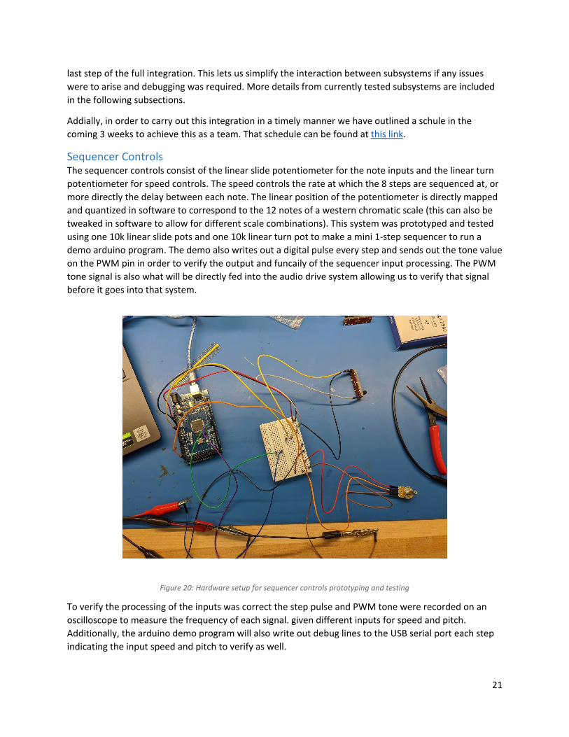
Sequencer Controls The sequencer controls consist of the linear slide potentiometer for the note inputs and the linear turn potentiometer for speed controls. The speed controls the rate at which the 8 steps are sequenced at, or more directly the delay between each note. The linear position of the potentiometer is directly mapped and quantized in software to correspond to the 12 notes of a western chromatic scale (this can also be tweaked in software to allow for different scale combinations). This system was prototyped and tested using one 10k linear slide pots and one 10k linear turn pot to make a mini 1-step sequencer to run a demo arduino program. The demo also writes out a digital pulse every step and sends out the tone value on the PWM pin in order to verify the output and funcaily of the sequencer input processing. The PWM tone signal is also what will be directly fed into the audio drive system allowing us to verify that signal before it goes into that system.
Figure 20: Hardware setup for sequencer controls prototyping and testing
To verify the processing of the inputs was correct the step pulse and PWM tone were recorded on an oscilloscope to measure the frequency of each signal. given different inputs for speed and pitch. Additionally, the arduino demo program will also write out debug lines to the USB serial port each step indicating the input speed and pitch to verify as well.
21
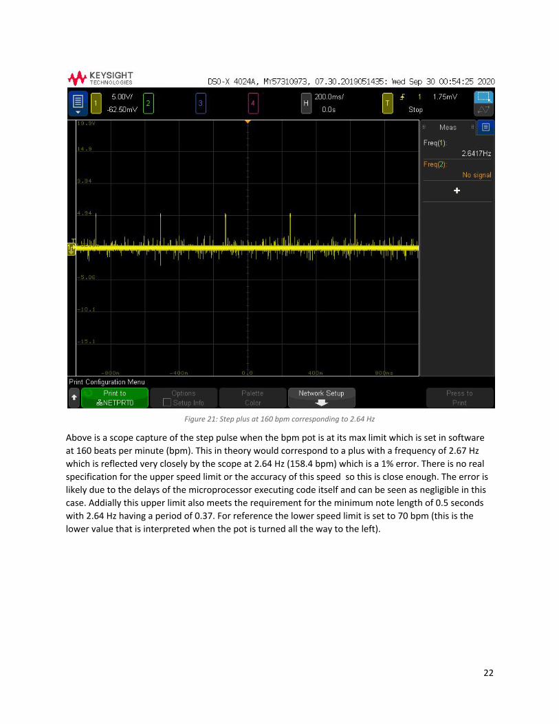
Figure 21: Step plus at 160 bpm corresponding to 2.64 Hz
Above is a scope capture of the step pulse when the bpm pot is at its max limit which is set in software at 160 beats per minute (bpm). This in theory would correspond to a plus with a frequency of 2.67 Hz which is reflected very closely by the scope at 2.64 Hz (158.4 bpm) which is a 1% error. There is no real specification for the upper speed limit or the accuracy of this speed so this is close enough. The error is likely due to the delays of the microprocessor executing code itself and can be seen as negligible in this case. Addially this upper limit also meets the requirement for the minimum note length of 0.5 seconds with 2.64 Hz having a period of 0.37. For reference the lower speed limit is set to 70 bpm (this is the lower value that is interpreted when the pot is turned all the way to the left).
22
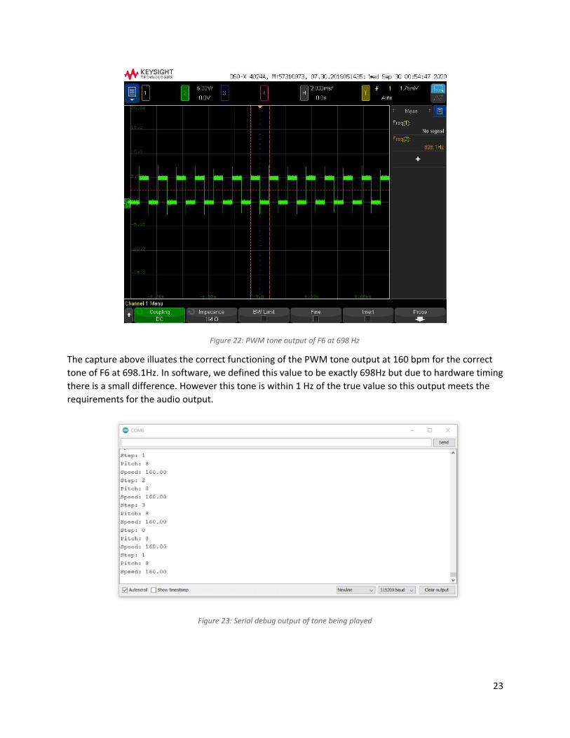
Figure 22: PWM tone output of F6 at 698 Hz
The capture above illuates the correct functioning of the PWM tone output at 160 bpm for the correct tone of F6 at 698.1Hz. In software, we defined this value to be exactly 698Hz but due to hardware timing there is a small difference. However this tone is within 1 Hz of the true value so this output meets the requirements for the audio output.
Figure 23: Serial debug output of tone being played
23
Above is a capture of the serial output from the arduino printing the debug statements in real time indicating what notes are being played each step and the speed value is being read. The output shown correlated with the two captures shown above with F6 being played at 160 bpm.
Based on these results, the sequencer controls have been fully tested with no issues and can be now integrated with the rest of the system.
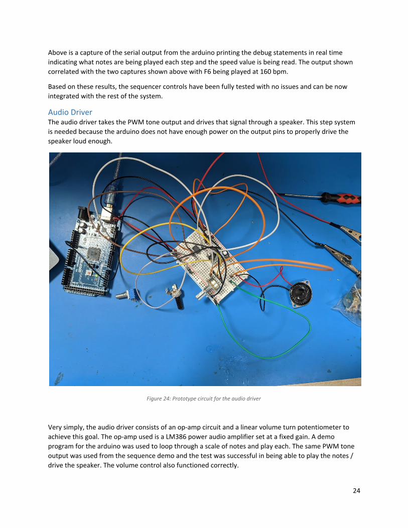
Audio Driver The audio driver takes the PWM tone output and drives that signal through a speaker. This step system is needed because the arduino does not have enough power on the output pins to properly drive the speaker loud enough.
Figure 24: Prototype circuit for the audio driver
Very simply, the audio driver consists of an op-amp circuit and a linear volume turn potentiometer to achieve this goal. The op-amp used is a LM386 power audio amplifier set at a fixed gain. A demo program for the arduino was used to loop through a scale of notes and play each. The same PWM tone output was used from the sequence demo and the test was successful in being able to play the notes / drive the speaker. The volume control also functioned correctly.
24
Based on these results, the audio driver and speaker have been fully tested with no issues and can be now integrated with the rest of the system. Minimal integration is needed with the sequencer controls demos to also add the audio and the only overlap between the two subsystems is the microcontroller / software.
Motor Driver There are two rotating dials on our device to provide feedback to the user of the step and pitch of the notes they are playing which change while the notes are being sequenced. In order to achieve position and speed control for these rotating indicators, stepper motes are being used to implement this feature. However to achieve the proper speed of the stepper motor to meet our BPM speed requirements we set it to meet the half second note length, we need to be able to drive our stepper motor at a higher voltage thus also rewiring a higher current. Additionally, something is also needed to process the correct signals to switch these currents in the right manner to make the stepper motor work. Two NEMA 17 Stepper Motor (SM-42BYG011-25) are being used for prototyping, each of which is rated for 12 Volts and 0.33 Amps and has. Each stepper motor has 2 coil windings as well.To probably drive these motors at this specification, 2 TB6612 DC/Stepper Motor Driver breakouts are used, each with 2 channels and each handling up to 1.2 Amps and 13.5 Volts. Thus, each board will be able to drive each stepper motor at its max rated 12 volts to achieve the fastest stepping speed.
A simple prototype was tested by hooking up one stepper board to one of the driver boards and using a simple demo program with the arduino stepper motor library to step the motor at a set speed in a simple pattern. However we ran into some issues with current railing of the motor driver board as well as overheating and frying of the driver board being used to test.
We were able to resolve the issue after conducting more step by step testing of the motor driver board. By being meticulous about the wiring, the setup of the power supply, and the control signals from the microcontroller, we were able to get the other motor driver board working with the servo at the speed we wanted. We believe the problem was a combination of not setting the overcurrent level on the power supply correctly and setting the speed of the severe too fast in the software (if you plot the actual speed of the servo vs. the set speed in the software you get a linear curve that flattens once you hit a high enough set speed). The combination of these two factors may have caused some funky switching behaviors of the driving transistors inside the motor driver that could have led to shorts or very high temperatures.
After resolving the issue we were able to get the stepper motor to step constantly at the speed and precision we wanted. Based on these results, the motor drivers and motors have been fully tested with no issues and can be now integrated with the rest of the system.
Requirements Decomposition The main requirements for the device are summarized below into several major categories. See here for a more detailed requirements decomposition.
● Aesthetically pleasing ○ Use analog sensor or "interesting" user interface to input notes ○ Must be an “interesting” design (as determined by instructors) ○ Show Product name, Class section/group number, GT/ECE logo ○ Must be intuitively usable
25
○ Must appear as a finished product: Painted, labeled, sealed, etc ○ No duct tape or other unsightly materials ○ Display interesting mechanical movement which corresponds to the notes played by the
user ● Safe to use
○ Max temperature of the case must not exceed 80 C ○ Must operate from 120VAC and consume no more than 50W ○ No exposed wires or conductors on the device and must conform to US National Electric
Code ○ AC power wiring must conform to U.S. National Electrical Code (NEC) standard ○ A commonly available input power connector must be used (no wires through holes) ○ Input power (AC or DC) must be fused or otherwise short-circuit protected ○ No sharp edges or corners ○ Device must operate completely in stand-alone mode, with no external PC/phone
control or connections ● Device controls, somewhat akin to a video recorder: REC/STOP/PLAY
○ Must be able to record and play 8 different frequecies: 110(A2), 123.471(B2), 130.813(C3), 146.832(D3), 164.814(E3), 174.614(F3), 195.998(G3), 207.652(G#3) +- 1Hz
○ Sculpture shall ganerate the associated notes as it records (but not mechanical movement)
○ Input a sequence of individual piches (notes) both in live play and record ○ Must be able to record note lengths as short as 0.5 sec ○ Device must be able to record a sequence of least 20 seconds; this means our device
mut store up to 40 steps given the 0.5 minium note length ○ Re-entering REC appends to last recording ○ Holding RESET for 3 sec. erases entire recording ○ Audio sequence recording activated when switched to REC mode ○ Live sequence mode is activated when PLAY mode is set ○ Sculpture generates the recorded audio sequence and moves mechanical elements in
rhythm with the music ○ Pose of the mechanism must be pre-programed to relate to pitch of the current note in
an interesting way ○ Playback shall be in half second steps ○ Must have one analog control (potentiometer, rotary encoder, etc.) For Example: front
panel volume control ○ Must continuously repeat recorded sequence (loop) ○ The sculpture should have at least two distinct motions ○ Each mechanism must be demonstrate covering a range of motion of at least 10 cm over
an entire play sequence ● Immobile base of certain size and be portable
○ The base must be heavy and have rubber feet. ○ The device must weigh less than 20 lbs. ○ In power-down state, or after ABORT robot must fit within a WxLxH: 35cm x 35 cm x 35
cm space ○ All movement must be confined within a space of WxLxH: 75cm x 75 cm x 75 cm
26
● Cost must not exceed $100 ○ Detail BOM of all parts must be delivered with product with required information ○ BOM must be delivered as an Excel Spreadsheet
● Additional Manufacturing Requirements ○ PCB dimensions must be within WxL: 15cm x 15cm and ○ PCB must be a 2-layer design, 1 oz. copper (36μm thick), fabricated on 1.6mm (0.062 in.)
thick FR-4 material. ○ Section and Group Number label must appear on PCB silkscreen or copper ○ Must submit schematic, and layout files (Gerber) ○ Assembly will be performed by manual soldering or oven reflow ○ Mechanically mount PCB in housing using standard hardware (standoffs, machine
screws, etc., no glue) ○ All off-PCB wiring must use insulated connectors or heat-shrink tubing (no exposed
conductors) ○ "Base housing must have a removable panel that allows visibility of all electronic
components while operating ○ (can be bottom side). Panel should be easily removable using screw drivers, etc. with no
more than 4 fasteners.
Test Plan Our test matrix is outlined here in our project requirements decomposition. Our plan is to follow the numbered requirements on the sheet. We have split our requirements into three tests: one to verify all the “by inspection” requirements, one to verify the “by demonstration requirements”, and one to verify the “by test / measurement” requirement. These are labeled as follows:
Test 1: Inspection (Insp) Test 2: Demonstration (Dem) Test 3: Test / Measurement
In order to test and demonstrate our various subsystems, we will test each subsystem alone, and then begin combining subsystems to allow more extensive tests. This process will eventually lead to full integration of all subsystems, giving us a fully functioning system. With this completed, we can then follow our Test Matrix to complete the verification of all of the project requirements.
Test 1: Inspection This test mainly verifies the mechanical and electrical build qualities of the devices as well as any visual design and spatial requirements of the device. This test was done though the final assembly phase since this best aligned with a lot of the build and design requirements for the device. This includes things such as measuring the dimensions of the final mechanical build of the box and the PCB, identifying the Buzz / GT logo and team name on the box as well as the silkscreen, and using proper fasteners and wire connectors. This is the simplest and most straightforward of the three tests.
Test 2: Demonstration This test mainly verifies the software, user operation, and circuit validation of the design. In this test the box is powered on and each of the main modes of operation of the sequencer is tested. First, the tester needs to verify the device is in idle mode once the device is on and make sure both dials are set pointing
27
up 90 degrees away from them. Idle mode should be indicated by two beeps in short succession played roughly every 1 second. Then, the live play mode should be entered, and the tester must verify the device is reading in the slider values as different note pitches when adjusted and that the indications move accordingly with the pitch set and the current step. The tester also needs to validate that once the 8th step is reached, the sequencer then loops back to the first step. Live play mode should be exited and the tester should enter back into idle mode. Then record mode should be entered and the tester should let the sequencer play out until all of the recording memory is full. At that point the tester must validate that the device will automatically go back into live play mode once recording memory is full. The tester should also try to go back into record mode with a full memory and validate the device automatically and immediately goes back to idle mode, indicating the recording memory is full. After this, record playback mode should be entered and the tester must validate that the sequence being played follows what was recorded, as well as the sequencer looping back once it reaches the last recorded note in memory. Then the tester must go back into idle mode, switch into reset mode, and validate that the device will automatically go back into idle mode once the recording memory is cleared. At this point the tester should go into record playback mode and verify the device automatically goes back to idle mode immediately indicating that recording memory was erased.
Test 3: Quantitative and Qualitative Testing This test is used to verify the numerical requirements that the device must meet. There are three categories of requirements that are tested: safety (temperature and power consumption), timing and sound, and device sizing and weight.
To test safety parameters, specifically, operating temperature of the enclosure should not exceed 80 C and the overall power consumption should be below 50 W, the device needs to be operated for a prolonged period of time (about 10 min). After the device has been operated for a period of time, the tester should use a temperature sensor to measure the temperature of the enclosure. Alternatively, the tester can carefully remain in physical contact with the enclosure during the operation, and if the temperature rise does not bring any discomfort, the test is passed. However, the use of a sensor is preferred, as the safer method. To verify power consumption, the tester can turn on the device and attach a current sensor to the main 12 V bus (if available). If the current reading is less than 4.1 A, the test is passed. If a current sensor is not available, the tester can leave the device operational, and then inspect the installed fuse. If the 3A fuse is intact, the power consumption is less than 50 W.
To test timing requirements, the tester should turn on the device, connect the speaker output to an oscilloscope, and measure the frequency at which the notes are played. Another method is to count the number of notes played in a 10 second time period: at the max BPM, there should be more than 20 notes played in 10 seconds (0.5 seconds per note). The accuracy of the note frequencies can be measured either with an oscilloscope or using a smartphone application.
28
Finally, to verify the sculpture sizing and weight, the tester can use a scale and a tape measure. If the device satisfies the requirements outlined in the decomposition table, the test is passed.
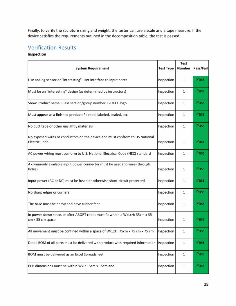
Verification Results Inspection
29
System Requirement Test Type Test
Number Pass/Fail
Use analog sensor or "interesting" user interface to input notes Inspection 1 Pass
Must be an “interesting” design (as determined by instructors) Inspection 1 Pass
Show Product name, Class section/group number, GT/ECE logo Inspection 1 Pass
Must appear as a finished product: Painted, labeled, sealed, etc Inspection 1 Pass
No duct tape or other unsightly materials Inspection 1 Pass
No exposed wires or conductors on the device and must confrom to US National Electric Code Inspection 1 Pass
AC power wiring must conform to U.S. National Electrical Code (NEC) standard Inspection 1 Pass
A commonly available input power connector must be used (no wires through holes) Inspection 1 Pass
Input power (AC or DC) must be fused or otherwise short-circuit protected Inspection 1 Pass
No sharp edges or corners Inspection 1 Pass
The base must be heavy and have rubber feet. Inspection 1 Pass
In power-down state, or after ABORT robot must fit within a WxLxH: 35cm x 35 cm x 35 cm space Inspection 1 Pass
All movement must be confined within a space of WxLxH: 75cm x 75 cm x 75 cm Inspection 1 Pass
Detail BOM of all parts must be delivered with product with required information Inspection 1 Pass
BOM must be delivered as an Excel Spreadsheet Inspection 1 Pass
PCB dimensions must be within WxL: 15cm x 15cm and Inspection 1 Pass
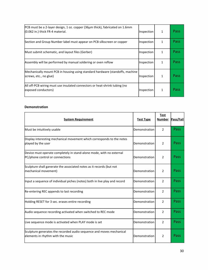
Demonstration
30
PCB must be a 2-layer design, 1 oz. copper (36μm thick), fabricated on 1.6mm (0.062 in.) thick FR-4 material. Inspection 1 Pass
Section and Group Number label must appear on PCB silkscreen or copper Inspection 1 Pass
Must submit schematic, and layout files (Gerber) Inspection 1 Pass
Assembly will be performed by manual soldering or oven reflow Inspection 1 Pass
Mechanically mount PCB in housing using standard hardware (standoffs, machine screws, etc., no glue) Inspection 1 Pass
All off-PCB wiring must use insulated connectors or heat-shrink tubing (no exposed conductors) Inspection 1 Pass
System Requirement Test Type Test
Number Pass/Fail
Must be intuitively usable Demonstration 2 Pass
Display interesting mechanical movement which corresponds to the notes played by the user Demonstration 2 Pass
Device must operate completely in stand-alone mode, with no external PC/phone control or connections Demonstration 2 Pass
Sculpture shall ganerate the associated notes as it records (but not mechanical movement) Demonstration 2 Pass
Input a sequence of individual piches (notes) both in live play and record Demonstration 2 Pass
Re-entering REC appends to last recording Demonstration 2 Pass
Holding RESET for 3 sec. erases entire recording Demonstration 2 Pass
Audio sequence recording activated when switched to REC mode Demonstration 2 Pass
Live sequence mode is activated when PLAY mode is set Demonstration 2 Pass
Sculpture generates the recorded audio sequence and moves mechanical elements in rhythm with the music Demonstration 2 Pass
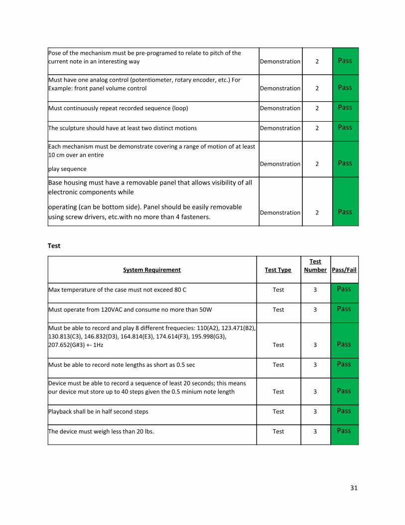
Test
31
Pose of the mechanism must be pre-programed to relate to pitch of the current note in an interesting way Demonstration 2 Pass
Must have one analog control (potentiometer, rotary encoder, etc.) For Example: front panel volume control Demonstration 2 Pass
Must continuously repeat recorded sequence (loop) Demonstration 2 Pass
The sculpture should have at least two distinct motions Demonstration 2 Pass
Each mechanism must be demonstrate covering a range of motion of at least 10 cm over an entire
play sequence Demonstration 2 Pass
Base housing must have a removable panel that allows visibility of all electronic components while
operating (can be bottom side). Panel should be easily removable
using screw drivers, etc.with no more than 4 fasteners. Demonstration 2 Pass
System Requirement Test Type Test
Number Pass/Fail
Max temperature of the case must not exceed 80 C Test 3 Pass
Must operate from 120VAC and consume no more than 50W Test 3 Pass
Must be able to record and play 8 different frequecies: 110(A2), 123.471(B2), 130.813(C3), 146.832(D3), 164.814(E3), 174.614(F3), 195.998(G3), 207.652(G#3) +- 1Hz Test 3 Pass
Must be able to record note lengths as short as 0.5 sec Test 3 Pass
Device must be able to record a sequence of least 20 seconds; this means our device mut store up to 40 steps given the 0.5 minium note length Test 3 Pass
Playback shall be in half second steps Test 3 Pass
The device must weigh less than 20 lbs. Test 3 Pass
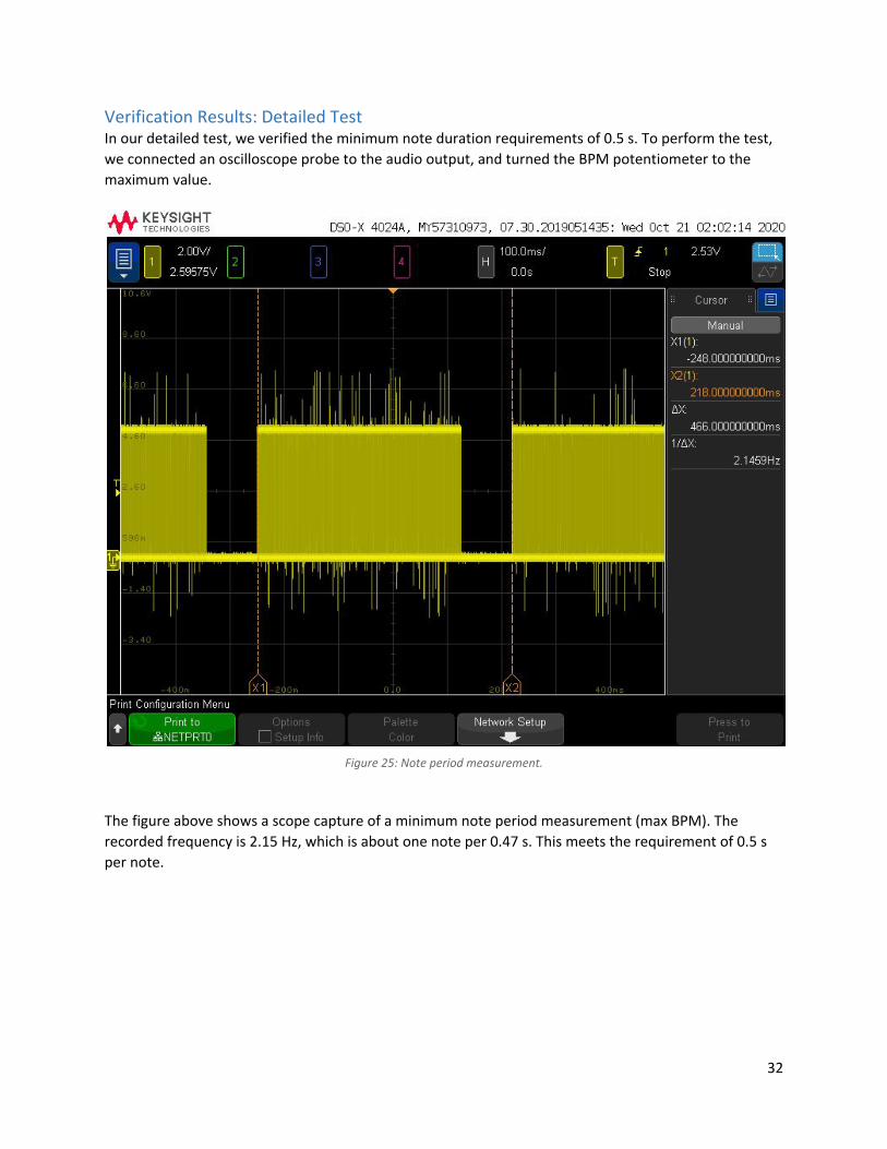
Verification Results: Detailed Test In our detailed test, we verified the minimum note duration requirements of 0.5 s. To perform the test, we connected an oscilloscope probe to the audio output, and turned the BPM potentiometer to the maximum value.
Figure 25: Note period measurement.
The figure above shows a scope capture of a minimum note period measurement (max BPM). The recorded frequency is 2.15 Hz, which is about one note per 0.47 s. This meets the requirement of 0.5 s per note.
32
Conclusion This project was completed for ECE 3872 as part of the ECE design course requirements. Throughout the semester we have learned a lot about the engineering design process and how to work with a team under challenging conditions. This project allowed us to experience how real products are actually made, as well as getting a lot of practice with rapid prototyping. Our team had varying backgrounds within the School of Electrical and Computer Engineering at Georgia Tech, so we were able to complement each other's strength to effectively create a fun and unique product - Air Sequencer. Even with the Coronavirus, the team was still able to effectively work together remotely and got each of the individual subsystems on par. With Divy as a remote member of the team and also not being able to be together physically, the team still worked through this challenge and effectively got the final result looking like a polished product.
The distribution of work for the remainder of the semester can be found in our final schedule here. This has been updated as of 11/06/2020 the due date of this project.
33
APPENDIX: CODE
#include <Stepper.h>
#define STEPS 200
//Stepper stepper(STEPS, 4, 5, 6, 7);
Stepper stepper_step(STEPS, 31, 33, 35, 37);
Stepper stepper_pitch(STEPS, 23, 25, 27, 29);
int current_pitch_position = 0;
int note_positions[8] = {0, 25, 50, 75, 100, 125, 150, 175};
int position_diff = 0;
int current_step_position = 0;
unsigned long StartTime;
unsigned long StopTime;
unsigned long ElapsedTime;
int mode = 0;
double step_time = 1;
int step_gate = 0.5;
int loop_length = 8;
int current_step = 0;
int looping = 0;
int current_step_pitch = 0;
34
#define recording_size 16
int recording[recording_size] = { -1, -1, -1, -1, -1, -1, -1, -1, -1, -1, -1, -1, -1, -1, -1, -1};
int scale_a_minor[8] = {220, 247, 262, 294, 330, 349, 392, 440};
int analog_note_inputs[8] = {A0, A1, A2, A3, A4, A5, A6, A7};
int audio_signal_output = 12;
int sequence_speed_input = A15;
double sequence_speed_min_bpm = 70;
double sequence_speed_max_bpm = 200;
double current_speed = 0;
char input;
#define RECORD_BTN 53
#define PLAY_BTN 51
#define LIVE_BTN 49
#define RESET_BTN 47
int find(int *a, int n, int key)
{
int i;
for (i = 0; i < n; i++)
{
if (a[i] == key)
35
{
return i;
}
}
return -1;
}
char get_input()
{
if (digitalRead(RECORD_BTN) == LOW)
{ return 'r';
}
if (digitalRead(PLAY_BTN) == LOW)
{ return 'p';
}
if (digitalRead(LIVE_BTN) == LOW)
{ return 'l';
}
if (digitalRead(RESET_BTN) == LOW)
{ return 'q';
}
return 0;
}
36
void enter_beep() {
tone(audio_signal_output, 500, 500);
delay(500);
tone(audio_signal_output, 800, 500);
delay(500);
delay(500);
}
void exit_beep() {
tone(audio_signal_output, 800, 500);
delay(500);
tone(audio_signal_output, 500, 500);
delay(500);
delay(500);
}
void idle_beep() {
tone(audio_signal_output, 500, 250);
delay(300);
tone(audio_signal_output, 500, 250);
delay(300);
}
void setup() {
Serial.begin(115200);
Serial.println("Live Sequence Function Demo");
37
stepper_step.setSpeed(120);
stepper_pitch.setSpeed(120);
pinMode(RECORD_BTN, INPUT);
pinMode(PLAY_BTN, INPUT);
pinMode(LIVE_BTN, INPUT);
pinMode(RESET_BTN, INPUT);
}
void loop()
{
idle_beep();
delay(1000);
// IDLE
if (mode == 0)
{
printf("Mode: IDLE\n");
// Check inputs for state transitions
input = get_input();
switch (input)
{
case 'l':
// printf("Live Pressed\n");
// printf("Going to LIVE SEQUENCE state\n");
mode = 1;
break;
case 'p':
38
// printf("Play Pressed\n");
// printf("Going to RECORD PLAYBACK state\n");
mode = 3;
break;
case 'r':
// printf("Record Pressed\n");
// printf("Going to RECORD state\n");
mode = 2;
break;
case 'q':
// printf("Reset Pressed\n");
// printf("Going to RESET state\n");
mode = 4;
break;
case 'd':
// printf("Debug Pressed\n");
// printf("Memory: \n");
// for (int i = 0; i < recording_size; i++)
// printf("%d ", recording[i]);
// printf("\n");
break;
}
}
// LIVE SEQUENCE
if (mode == 1)
{
enter_beep();
39
// printf("Mode: LIVE SEQUENCE\n");
looping = 1;
current_step = 0;
while (looping)
{
current_step_pitch = map(analogRead(analog_note_inputs[current_step]), 0, 1023, 7, 0);
current_speed = double(analogRead(sequence_speed_input)) / 1023 * (sequence_speed_max_bpm - sequence_speed_min_bpm) + sequence_speed_min_bpm;
step_time = 60 / current_speed;
tone(audio_signal_output, scale_a_minor[current_step_pitch]);
position_diff = note_positions[current_step_pitch] - current_pitch_position;
if (position_diff > 100) {
position_diff = position_diff - 200;
}
if (position_diff < -100) {
position_diff = position_diff + 200;
}
StartTime = millis();
stepper_pitch.step(position_diff);
StopTime = millis();
ElapsedTime = StopTime - StartTime;
current_pitch_position = (current_pitch_position + position_diff) % 200;
delay( max((step_time * 1000) - ElapsedTime, 0) );
noTone(audio_signal_output);
stepper_step.step(25);
current_step_position = (current_step_position + 25) % 200;
40
input = get_input();
if (input == 'l')
{
stepper_pitch.step(-1 * current_pitch_position);
current_pitch_position = 0;
stepper_step.step(-1 * current_step_position);
current_step_position = 0;
// printf("Stop Pressed\n");
// printf("Live Play Stopped\n");
// printf("Going to IDLE state\n");
looping = 0;
mode = 0;
exit_beep();
}
current_step++;
if (current_step >= loop_length)
{
current_step = 0;
}
}
}
// RECORD
if (mode == 2)
41
{
enter_beep();
int starting_index = find(recording, recording_size, -1);
// printf("Starting Index: %d\n", starting_index);
current_step = starting_index;
if (starting_index == -1) {
// printf("Recording Memory Full\n");
// printf("Going to IDLE State\n");
mode = 0;
exit_beep();
}
else
{
while (current_step < recording_size)
{
current_step_pitch = map(analogRead(analog_note_inputs[current_step]), 0, 1023, 7, 0);
recording[current_step] = current_step_pitch;
current_speed = double(analogRead(sequence_speed_input)) / 1023 * (sequence_speed_max_bpm - sequence_speed_min_bpm) + sequence_speed_min_bpm;
step_time = 60 / current_speed;
tone(audio_signal_output, scale_a_minor[current_step_pitch]);
position_diff = note_positions[current_step_pitch] - current_pitch_position;
if (position_diff > 100) {
position_diff = position_diff - 200;
}
if (position_diff < -100) {
position_diff = position_diff + 200;
42
}
StartTime = millis();
stepper_pitch.step(position_diff);
StopTime = millis();
ElapsedTime = StopTime - StartTime;
current_pitch_position = (current_pitch_position + position_diff) % 200;
delay( max((step_time * 1000) - ElapsedTime, 0) );
noTone(audio_signal_output);
stepper_step.step(25);
current_step_position = (current_step_position + 25) % 200;
input = get_input();
if (input == 'r')
{
// printf("Stop Pressed\n");
// printf("Recording Stopped\n");
// printf("Going to IDLE state\n");
stepper_pitch.step(-1 * current_pitch_position);
current_pitch_position = 0;
stepper_step.step(-1 * current_step_position);
current_step_position = 0;
mode = 0;
break;
exit_beep();
};
43
current_step = current_step + 1;
}
if (current_step == recording_size)
{
// printf("Recording Memory Full\n");
// printf("Going to IDLE State\n");
stepper_pitch.step(-1 * current_pitch_position);
current_pitch_position = 0;
stepper_step.step(-1 * current_step_position);
current_step_position = 0;
mode = 0;
exit_beep();
}
}
}
// RECORD PLAYBACK
if (mode == 3)
{
enter_beep();
int ending_index = find(recording, recording_size, -1);
// printf("Ending Index: %d\n", ending_index);
if (ending_index == -1)
{
ending_index = recording_size - 1;
}
if (ending_index == 0)
44
{
// printf("Recording Memory Empty\n");
// printf("Going to IDLE State\n");
stepper_pitch.step(-1 * current_pitch_position);
current_pitch_position = 0;
stepper_step.step(-1 * current_step_position);
current_step_position = 0;
mode = 0;
exit_beep();
}
else
{
current_step = 0;
looping = 1;
while (looping)
{
current_step_pitch = recording[current_step];
recording[current_step] = current_step_pitch;
current_speed = double(analogRead(sequence_speed_input)) / 1023 * (sequence_speed_max_bpm - sequence_speed_min_bpm) + sequence_speed_min_bpm;
step_time = 60 / current_speed;
tone(audio_signal_output, scale_a_minor[current_step_pitch]);
position_diff = note_positions[current_step_pitch] - current_pitch_position;
if (position_diff > 100) {
position_diff = position_diff - 200;
}
45
if (position_diff < -100) {
position_diff = position_diff + 200;
}
StartTime = millis();
stepper_pitch.step(position_diff);
StopTime = millis();
ElapsedTime = StopTime - StartTime;
current_pitch_position = (current_pitch_position + position_diff) % 200;
delay( max((step_time * 1000) - ElapsedTime, 0) );
noTone(audio_signal_output);
stepper_step.step(25);
current_step_position = (current_step_position + 25) % 200;
input = get_input();
if (input == 'p')
{
// printf("Stop Pressed\n");
// printf("Recording Playback Stopped\n");
// printf("Going to IDLE state\n");
stepper_pitch.step(-1 * current_pitch_position);
current_pitch_position = 0;
stepper_step.step(-1 * current_step_position);
current_step_position = 0;
looping = 0;
mode = 0;
exit_beep();
46
}
current_step = current_step + 1;
if (current_step >= ending_index)
{
current_step = 0;
}
}
}
}
// RESET
if (mode == 4)
{
enter_beep();
// printf("Mode: RESET\n");
// printf("Clearing Recording Memeory\n");
for (int i = 0; i < recording_size; i++)
{
recording[i] = -1;
}
// printf("Recording Memeory Cleared\n");
// printf("Going to IDLE State\n");
stepper_pitch.step(-1 * current_pitch_position);
current_pitch_position = 0;
stepper_step.step(-1 * current_step_position);
current_step_position = 0;
mode = 0;
47
exit_beep();
}
}
48
![Sequencer 1, Sequencer 2 or Drum - Arturia - Home · PDF file—Sequencer 1, Sequencer 2 or Drum SHIFT + [>>] = Extend sequence SHIFT + Knob 1 = Offset value for all active steps SHIFT](https://img.pdfslide.us/doc/110x75/5a7941a77f8b9a51548d4279/sequencer-1-sequencer-2-or-drum-arturia-home-sequencer-1-sequencer-2-or.jpg)