Embed Size (px)
Citation preview
State of California AIR RESOURCES BOARD
EXECUTIVE ORDER VR-302-B
Standing Loss Control Vapor Recovery System for New Installations of
Aboveground Storage Tanks
WHEREAS, the California Air Resources Board (ARB) has established, pursuant to California Health and Safety Code sections 39600, 39601 and 41954, certification procedures for systems designed for the control of standing loss emissions for aboveground storage tanks in its CP-206, Certification Procedure for Vapor Recovery Systems at Gasoline Dispensing Facilities Using Aboveground Storage Tanks (Certification Procedure) adopted on May 2, 2008, incorporated by reference in California Code of Regulations, section 94016; WHEREAS, ARB has established, pursuant to California Health and Safety Code sections 39600, 39601, 39607, and 41954, test procedures for determining compliance with performance standards for standing loss control vapor recovery systems; WHEREAS, ConVault® (Applicant) requested certification of the Standing Loss Vapor Recovery System for new installations of aboveground storage tanks (AST) pursuant to the Certification Procedure; WHEREAS, the Certification Procedure provides that the ARB Executive Officer shall issue an Executive Order if he or she determines that the standing loss control vapor recovery system for new ASTs conforms to all of the applicable requirements set forth in the Certification Procedure; WHEREAS, I, James N. Goldstene, Executive Officer, find that the Applicant’s Standing Loss Vapor Recovery System conforms with all requirements set forth in the Certification Procedure and results in a vapor recovery system which shall not exceed 0.57 pounds of hydrocarbons per 1,000 gallons of ullage per day when tested pursuant to TP-206.1, Determination of Emission Factor for Standing Loss Control Vapor Recovery Systems Using Temperature Attenuation Factor at Gasoline Dispensing Facilities with Aboveground Storage Tanks (May 2, 2008) NOW, THEREFORE, IT IS HEREBY ORDERED that the Applicant’s Standing Loss Vapor Recovery System is certified not to exceed 0.57 pounds of hydrocarbon per 1,000 gallons of ullage per day when installed, operated, and maintained as specified herein and in the following exhibits. Exhibit 1 contains an equipment list of the certified components. Exhibit 2 contains the performance standards and specifications and typical installation drawings. Exhibit 3 contains
-2-
Standing Loss Control Vapor Recovery System for New Installations of Aboveground Storage Tanks - VR-302-B
the manufacturing performance standards and specifications. Exhibit 4 contains the Standing Loss Control Vapor Recovery System warranty. IT IS FURTHER ORDERED that compliance with the applicable certification requirements, rules and regulations of the Division of Measurement Standards of the Department of Food and Agriculture, the Office of the State Fire Marshal of the Department of Forestry and Fire Protection, and the Division of Occupational Safety and Health of the Department of Industrial Relations, are made conditions of this certification. IT IS FURTHER ORDERED that the manufacturers of components listed in Exhibit 1 shall provide a warranty to each of their components certified herein. The warranty shall be passed on to each subsequent purchaser within the warranty period. The warranty shall include the ongoing compliance with all applicable performance standards and specifications and shall comply with all warranty requirements in Section 17.5 of the Certification Procedure. Manufacturers may specify that the warranty is contingent upon the use of trained installers. IT IS FURTHER ORDERED that the certified Standing Loss Vapor Recovery System shall be installed, operated, and maintained in accordance with ARB Approved Installation, Operation, and Maintenance Manual. A copy of this Executive Order and the ARB Approved Installation, Operation and Maintenance Manual for Standing Loss Control Vapor Recovery System for New Installations of Aboveground Storage Tanks shall be maintained at each Gasoline Dispensing Facility (GDF) where a certified Standing Loss Vapor Recovery System is installed. IT IS FURTHER ORDERED that equipment listed in Exhibit 1, unless exempted, shall be clearly identified by a permanent identification showing the manufacturer’s name, model number, and serial number. IT IS FURTHER ORDERED that any alteration in the equipment parts, design, installation, or operation of the system certified, hereby is prohibited and deemed inconsistent with this certification, unless the alteration has been submitted in writing and approved in writing by the Executive Officer or Executive Officer delegate. IT IS FURTHER ORDERED that the following requirements are made a condition of certification. Testing the Pressure/Vacuum (PV) Vent valve will be at the option of the local districts. If P/V valve testing is required by the district, the test shall be conducted in accordance with TP-201.1E, Leak Rate and Cracking Pressure of Pressure/Vacuum Vent Valves (October 8, 2003) and Exhibit 2. Notification of testing, and submittal of test results, shall be done in accordance with local district requirements and pursuant to the policies established by that district. Alternative


Executive Order VR-302-B Standing Loss Control Vapor Recovery System for New Installations of Aboveground Storage Tanks
Exhibit 1, Page 1
Exhibit 1 Equipment List
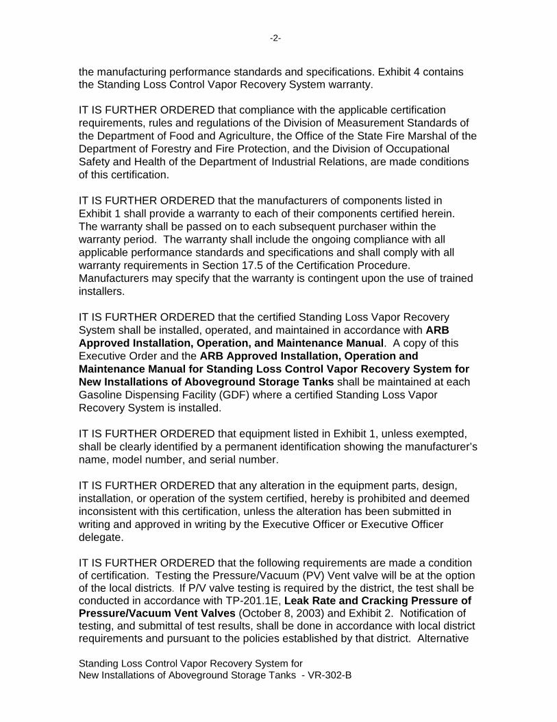
Equipment Manuf acturer/Model Number A. Pressure/Vacuum Vent Valve Husky 5885 (Figure 1A-1)
Protected Aboveground Modern Custom Fabrication Storage Tanks SuperVault Model MH
Serial Number 1XXXXX where X = number from 0 - 9 (Figure 1A-2)
B. Pressure/Vacuum Vent Valve Husky 5885 (Figure 1A-1)
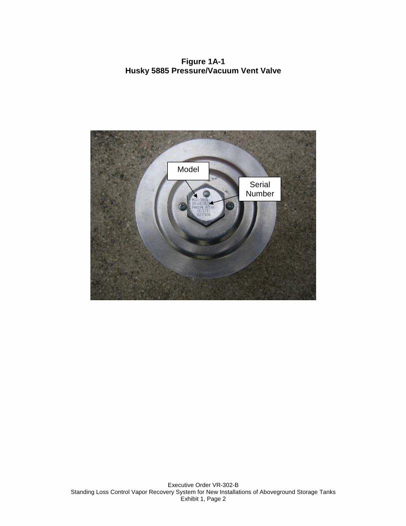
Protected Aboveground Steel Tank Institute Storage Tanks Fireguard Protected AST Serial Number XXXXXX where X = number from 0-9 (Figure 1A-3)
C. Pressure/Vacuum Vent Valve Husky 5885 (Figure 1A-1)
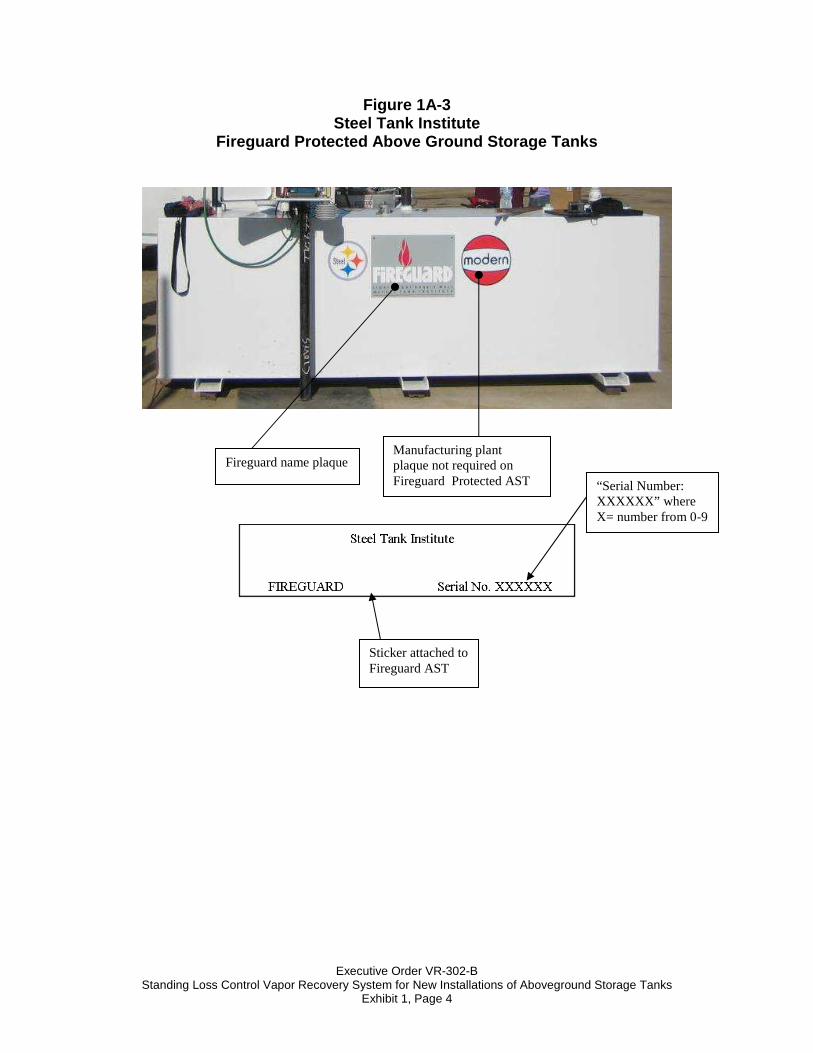
Protected Aboveground ConVault® , Inc ConVault ASTs Serial Number Z XXXXXX where Z = letters X = numbers from 0-9 (Figure 1 A-4)
Executive Order VR-302-B Standing Loss Control Vapor Recovery System for New Installations of Aboveground Storage Tanks
Exhibit 1, Page 2
Figure 1A-1
Husky 5885 Pressure/Vacuum Vent Valve
Model
Serial Number

Executive Order VR-302-B Standing Loss Control Vapor Recovery System for New Installations of Aboveground Storage Tanks
Exhibit 1, Page 3
Figure 1A-2 Modern Custom Fabrication
SuperVault MH Series Protected Above Ground Storage Tanks
Label – Metal plaque mounted to AST
Model “MH”
“Serial Number:: 1XXXXX” where X=number from 0 to 9
Executive Order VR-302-B Standing Loss Control Vapor Recovery System for New Installations of Aboveground Storage Tanks
Exhibit 1, Page 4
Figure 1A-3 Steel Tank Institute
Fireguard Protected Above Ground Storage Tanks
“Serial Number: XXXXXX” where X= number from 0-9
Fireguard name plaque
Sticker attached to Fireguard AST
Manufacturing plant plaque not required on Fireguard Protected AST
Executive Order VR-302-B Standing Loss Control Vapor Recovery System for New Installations of Aboveground Storage Tanks
Exhibit 1, Page 5
Figure 1A-4
ConVault ® Inc ConVault Aboveground Storage Tanks
Label - Aluminum Plate mounted to AST
Model Number Designation
1 2 3 4 5 6 7 8
W R, C or S M, N, or NF
__' D or E
125-12K
1, 2, 3 or 9 S or C __' or F
Item Tank Feature Nomenclature
1 Warranty Type W = New Warranty
2 Primary Containment R= rectangular, C = cylindrical,
3 Secondary Containment M = metallic, N = nonmetallic,
Blank = single, D = dual, side-by-side, 4 Compartment
Configuration E= multi, end-to-end
Capacity, normal 125 gallon to 12,000, for multi- 5
gallonage of each compartment may use 4K/4K/4K e.g.
6 Warranty Period 9 <10 yr, 1 = 10 yr, 2 = 20 yr, 3 = 30 yr
7 Fittings Layout S = Standard layout, C = Custom Layout
8 Spill Container Blank = none, F = Integral Spill Container
ConVault® name plaque
Size of Tank
Serial Number Z XXXXXX where Z = Letters X = numbers from 0-9
Executive Order VR-302-B, Standing Loss Control Vapor Recovery System for New Installations of Aboveground Storage Tanks
Exhibit 2, Page 1
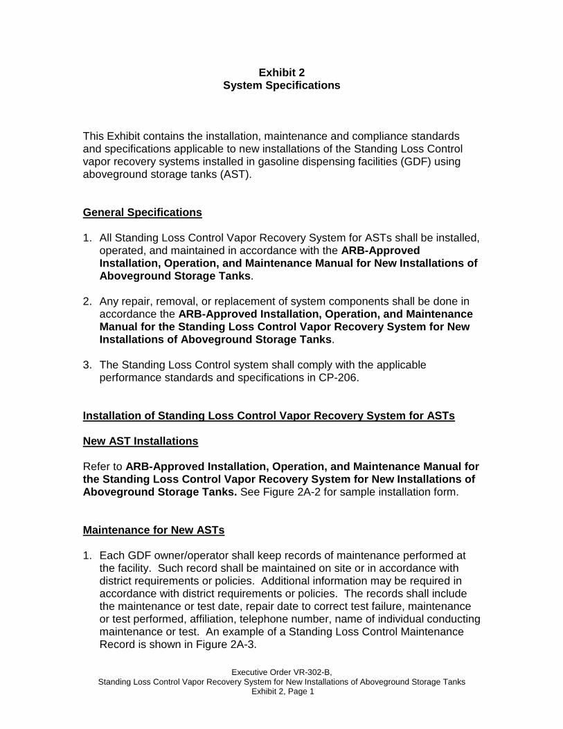
Exhibit 2 System Specifications
This Exhibit contains the installation, maintenance and compliance standards and specifications applicable to new installations of the Standing Loss Control vapor recovery systems installed in gasoline dispensing facilities (GDF) using aboveground storage tanks (AST). General Specifications 1. All Standing Loss Control Vapor Recovery System for ASTs shall be installed,
operated, and maintained in accordance with the ARB-Approved Installation, Operation, and Maintenance Manual for New Installations of Aboveground Storage Tanks.
2. Any repair, removal, or replacement of system components shall be done in
accordance the ARB-Approved Installation, Operation, and Maintenance Manual for the Standing Loss Control Vapor Recovery System for New Installations of Aboveground Storage Tanks.
3. The Standing Loss Control system shall comply with the applicable
performance standards and specifications in CP-206. Installation of Standing Loss Control Vapor Recovery System for ASTs New AST Installations Refer to ARB-Approved Installation, Operation, and Maintenance Manual for the Standing Loss Control Vapor Recovery System for New Installations of Aboveground Storage Tanks. See Figure 2A-2 for sample installation form. Maintenance for New ASTs 1. Each GDF owner/operator shall keep records of maintenance performed at
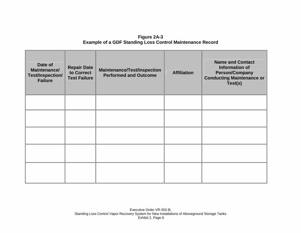
the facility. Such record shall be maintained on site or in accordance with district requirements or policies. Additional information may be required in accordance with district requirements or policies. The records shall include the maintenance or test date, repair date to correct test failure, maintenance or test performed, affiliation, telephone number, name of individual conducting maintenance or test. An example of a Standing Loss Control Maintenance Record is shown in Figure 2A-3.

Executive Order VR-302-B, Standing Loss Control Vapor Recovery System for New Installations of Aboveground Storage Tanks
Exhibit 2, Page 2
2. Maintenance shall be conducted in accordance with the maintenance section
of ARB-Approved Installation, Operation, and Maintenance Manual for the Standing Loss Control Vapor Recovery System for New Installations of Aboveground Storage Tanks.
Compliance Requirements for New AST Installations A. Pressure/Vacuum Vent Valves for Aboveground Storage Tank Vent Pipes
1. No more than three certified pressure/vacuum (P/V) vent valves listed in Exhibit 1 shall be installed on any GDF AST system.
2. Compliance determination of the following P/V valve performance
specifications shall be at the option of the districts:
a. The leak rate of each P/V valve shall not exceed 0.05 cubic feet per hour (CFH) at 2.00 inches of H2O positive pressure and 0.21 CFH at -4.00 inches of H2O negative pressure as determined by TP-201.1E, Leak Rate and Cracking Pressure of Pressure/Vacuum Vent Valves (October 8, 2003).
b. The positive pressure setting is 2.5 to 6.0 inches of H2O and the
negative pressure setting is 6.0 to 10.0 inches of H2O as determined by TP-201.1E, Leak Rate and Cracking Pressure of Pressure/Vacuum Vent Valves (October 8, 2003).
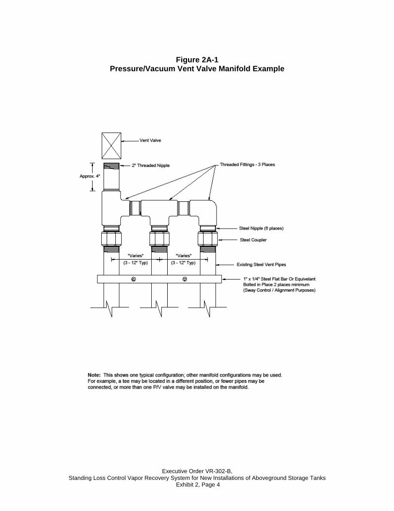
3. A manifold may be installed on the vent pipes to reduce the number of
potential leak sources and P/V valves installed. Vent pipe manifolds shall be constructed of steel pipe or an equivalent material that has been listed for use with gasoline. If a material other than steel is used, the GDF operator shall make available information demonstrating that the material is compatible for use with gasoline. One example of a typical vent pipe manifold is shown in Figure 2A-1. This shows only one typical configuration; other manifold configurations may be used. For example, a tee may be located in a different position, or fewer pipes may be connected, or more than one P/V valve may be installed on the manifold.
4. Each P/V valve shall have permanently affixed to it a yellow or gold-
colored label with black lettering stating the following specifications:
Positive pressure setting: 2.5 to 6.0 inches H2O Negative pressure setting: 6.0 to 10.0 inches H2O Positive Leakrate: 0.05 CFH at 2.0 inches H2O Negative Leakrate: 0.21 CFH at -4.0 inches H2O
Executive Order VR-302-B, Standing Loss Control Vapor Recovery System for New Installations of Aboveground Storage Tanks
Exhibit 2, Page 3
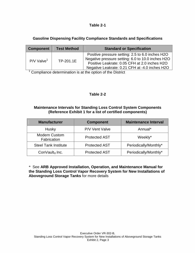
Table 2-1
Gasoline Dispensing Facility Compliance Standards and Specifications
Component Test Method Standard or Specification
P/V Valve1 TP-201.1E
Positive pressure setting: 2.5 to 6.0 inches H2O Negative pressure setting: 6.0 to 10.0 inches H2O
Positive Leakrate: 0.05 CFH at 2.0 inches H2O Negative Leakrate: 0.21 CFH at -4.0 inches H2O
1 Compliance determination is at the option of the District
Table 2-2
Maintenance Intervals for Standing Loss Control System Components (Reference Exhibit 1 for a list of certified components)
Manufacturer Component Maintenance Interval
Husky P/V Vent Valve Annual*
Modern Custom Fabrication
Protected AST Weekly*
Steel Tank Institute Protected AST Periodically/Monthly*
ConVault® Inc. Protected AST Periodically/Monthly*
* See ARB Approved Installation, Operation, and Maintenance Manual for the Standing Loss Control Vapor Recovery System for New Installations of Aboveground Storage Tanks for more details
Executive Order VR-302-B, Standing Loss Control Vapor Recovery System for New Installations of Aboveground Storage Tanks
Exhibit 2, Page 4
Figure 2A-1
Pressure/Vacuum Vent Valve Manifold Example
Executive Order VR-302-B, Standing Loss Control Vapor Recovery System for New Installations of Aboveground Storage Tanks
Exhibit 2, Page 5
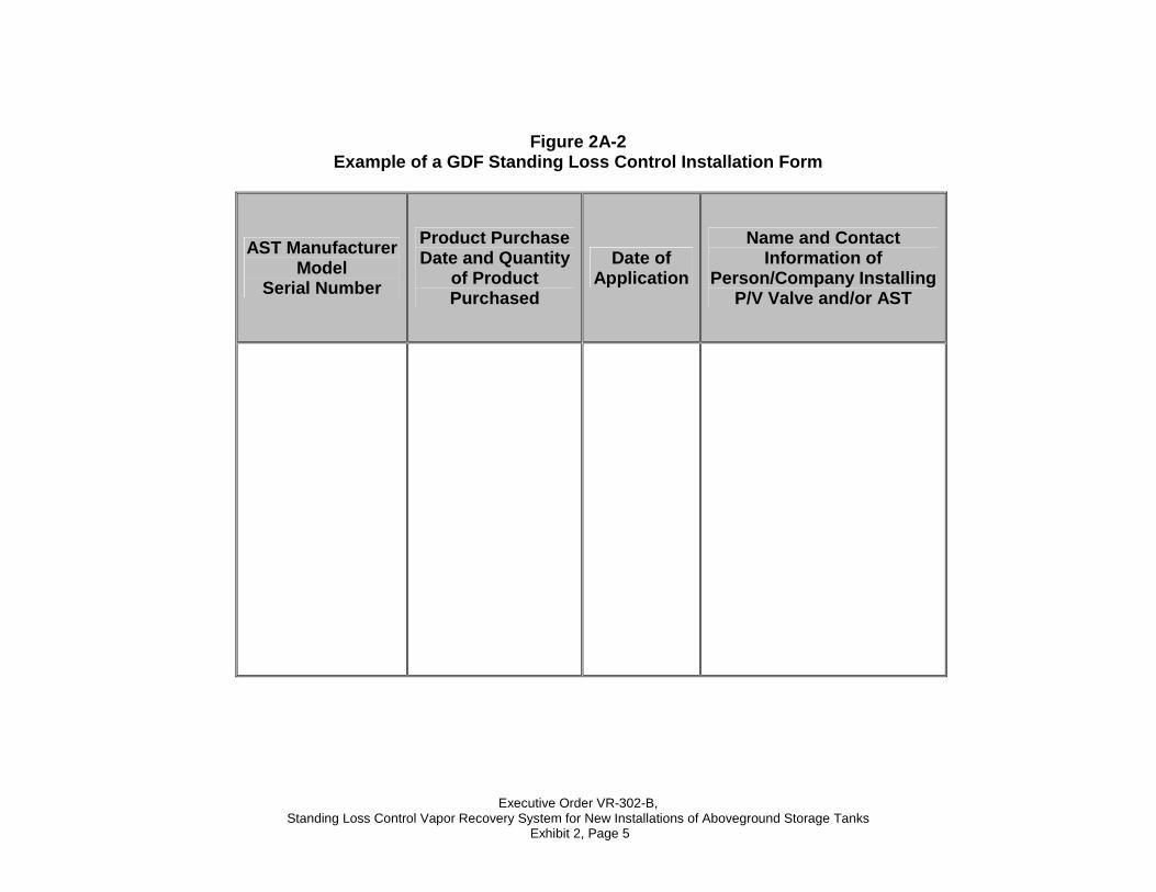
Figure 2A-2 Example of a GDF Standing Loss Control Installation Form
AST Manufacturer Model
Serial Number
Product Purchase Date and Quantity
of Product Purchased
Date of Application
Name and Contact Information of
Person/Company Installing P/V Valve and/or AST
Executive Order VR-302-B, Standing Loss Control Vapor Recovery System for New Installations of Aboveground Storage Tanks
Exhibit 2, Page 6
Figure 2A-3 Example of a GDF Standing Loss Control Maintenance Record
Date of Maintenance/
Test/Inspection/Failure
Repair Date to Correct
Test Failure
Maintenance/Test/Inspection Performed and Outcome Affiliation
Name and Contact Information of
Person/Company Conducting Maintenance or
Test(s)
Executive Order VR-302-B, Standing Loss Control Vapor Recovery System for New Installations of Aboveground Storage Tanks
Exhibit 3, Page 1
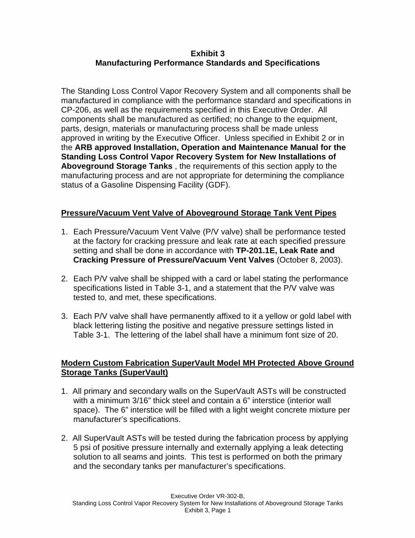
Exhibit 3 Manufacturing Performance Standards and Specificati ons
The Standing Loss Control Vapor Recovery System and all components shall be manufactured in compliance with the performance standard and specifications in CP-206, as well as the requirements specified in this Executive Order. All components shall be manufactured as certified; no change to the equipment, parts, design, materials or manufacturing process shall be made unless approved in writing by the Executive Officer. Unless specified in Exhibit 2 or in the ARB approved Installation, Operation and Maintenance Manual for the Standing Loss Control Vapor Recovery System for New Installations of Aboveground Storage Tanks , the requirements of this section apply to the manufacturing process and are not appropriate for determining the compliance status of a Gasoline Dispensing Facility (GDF). Pressure/Vacuum Vent Valve of Aboveground Storage T ank Vent Pipes 1. Each Pressure/Vacuum Vent Valve (P/V valve) shall be performance tested
at the factory for cracking pressure and leak rate at each specified pressure setting and shall be done in accordance with TP-201.1E, Leak Rate and Cracking Pressure of Pressure/Vacuum Vent Valves (October 8, 2003).
2. Each P/V valve shall be shipped with a card or label stating the performance
specifications listed in Table 3-1, and a statement that the P/V valve was tested to, and met, these specifications.
3. Each P/V valve shall have permanently affixed to it a yellow or gold label with
black lettering listing the positive and negative pressure settings listed in Table 3-1. The lettering of the label shall have a minimum font size of 20.
Modern Custom Fabrication SuperVault Model MH Prote cted Above Ground Storage Tanks (SuperVault)
1. All primary and secondary walls on the SuperVault ASTs will be constructed
with a minimum 3/16” thick steel and contain a 6” interstice (interior wall space). The 6” interstice will be filled with a light weight concrete mixture per manufacturer’s specifications.
2. All SuperVault ASTs will be tested during the fabrication process by applying 5 psi of positive pressure internally and externally applying a leak detecting solution to all seams and joints. This test is performed on both the primary and the secondary tanks per manufacturer’s specifications.
Executive Order VR-302-B, Standing Loss Control Vapor Recovery System for New Installations of Aboveground Storage Tanks
Exhibit 3, Page 2
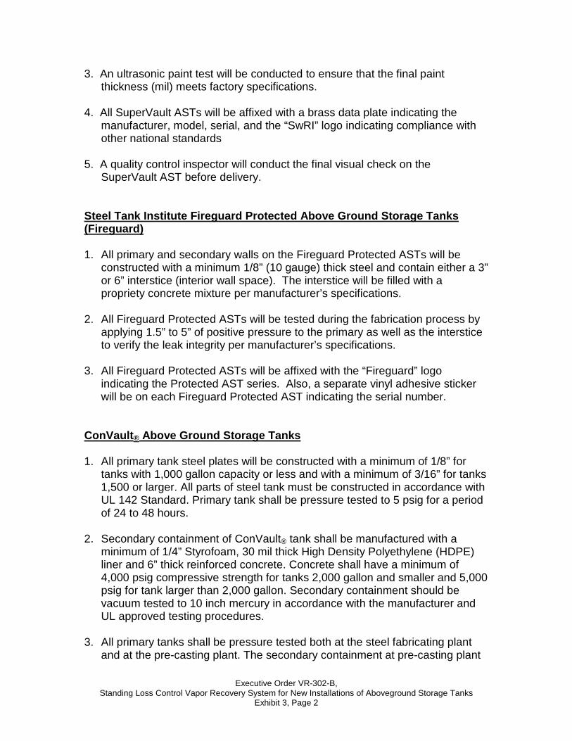
3. An ultrasonic paint test will be conducted to ensure that the final paint thickness (mil) meets factory specifications.
4. All SuperVault ASTs will be affixed with a brass data plate indicating the manufacturer, model, serial, and the “SwRI” logo indicating compliance with other national standards
5. A quality control inspector will conduct the final visual check on the SuperVault AST before delivery.
Steel Tank Institute Fireguard Protected Above Grou nd Storage Tanks (Fireguard) 1. All primary and secondary walls on the Fireguard Protected ASTs will be
constructed with a minimum 1/8” (10 gauge) thick steel and contain either a 3” or 6” interstice (interior wall space). The interstice will be filled with a propriety concrete mixture per manufacturer’s specifications.
2. All Fireguard Protected ASTs will be tested during the fabrication process by
applying 1.5” to 5” of positive pressure to the primary as well as the interstice to verify the leak integrity per manufacturer’s specifications.
3. All Fireguard Protected ASTs will be affixed with the “Fireguard” logo
indicating the Protected AST series. Also, a separate vinyl adhesive sticker will be on each Fireguard Protected AST indicating the serial number.
ConVault ® Above Ground Storage Tanks 1. All primary tank steel plates will be constructed with a minimum of 1/8” for
tanks with 1,000 gallon capacity or less and with a minimum of 3/16” for tanks 1,500 or larger. All parts of steel tank must be constructed in accordance with UL 142 Standard. Primary tank shall be pressure tested to 5 psig for a period of 24 to 48 hours.
2. Secondary containment of ConVault® tank shall be manufactured with a
minimum of 1/4” Styrofoam, 30 mil thick High Density Polyethylene (HDPE) liner and 6” thick reinforced concrete. Concrete shall have a minimum of 4,000 psig compressive strength for tanks 2,000 gallon and smaller and 5,000 psig for tank larger than 2,000 gallon. Secondary containment should be vacuum tested to 10 inch mercury in accordance with the manufacturer and UL approved testing procedures.
3. All primary tanks shall be pressure tested both at the steel fabricating plant
and at the pre-casting plant. The secondary containment at pre-casting plant
Executive Order VR-302-B, Standing Loss Control Vapor Recovery System for New Installations of Aboveground Storage Tanks
Exhibit 3, Page 3
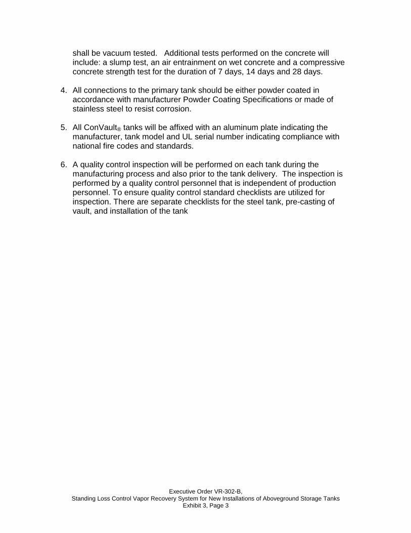
shall be vacuum tested. Additional tests performed on the concrete will include: a slump test, an air entrainment on wet concrete and a compressive concrete strength test for the duration of 7 days, 14 days and 28 days.
4. All connections to the primary tank should be either powder coated in
accordance with manufacturer Powder Coating Specifications or made of stainless steel to resist corrosion.
5. All ConVault® tanks will be affixed with an aluminum plate indicating the
manufacturer, tank model and UL serial number indicating compliance with national fire codes and standards.
6. A quality control inspection will be performed on each tank during the
manufacturing process and also prior to the tank delivery. The inspection is performed by a quality control personnel that is independent of production personnel. To ensure quality control standard checklists are utilized for inspection. There are separate checklists for the steel tank, pre-casting of vault, and installation of the tank
Executive Order VR-302-B, Standing Loss Control Vapor Recovery System for New Installations of Aboveground Storage Tanks
Exhibit 3, Page 4
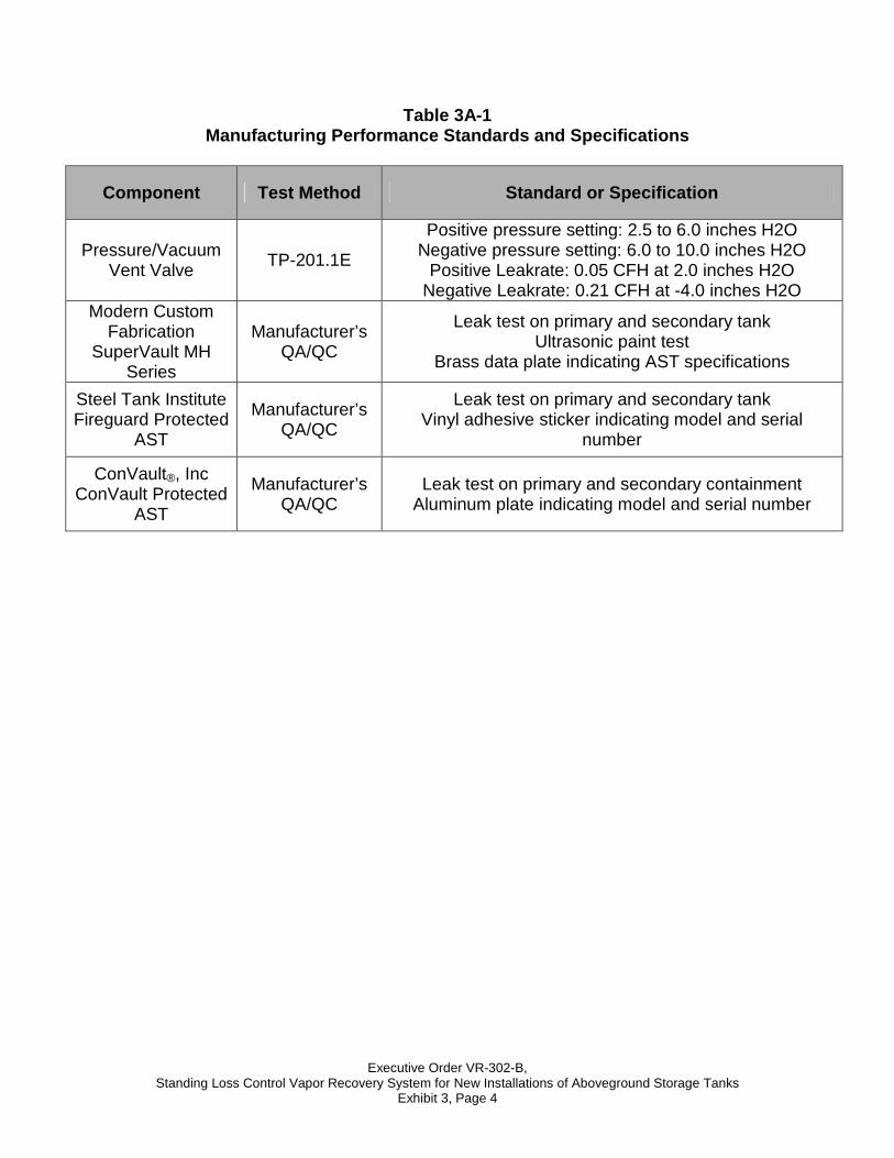
Table 3A-1 Manufacturing Performance Standards and Specificati ons
Component Test Method Standard or Specification
Pressure/Vacuum Vent Valve
TP-201.1E
Positive pressure setting: 2.5 to 6.0 inches H2O Negative pressure setting: 6.0 to 10.0 inches H2O
Positive Leakrate: 0.05 CFH at 2.0 inches H2O Negative Leakrate: 0.21 CFH at -4.0 inches H2O
Modern Custom Fabrication
SuperVault MH Series
Manufacturer’s QA/QC
Leak test on primary and secondary tank Ultrasonic paint test
Brass data plate indicating AST specifications
Steel Tank Institute Fireguard Protected
AST
Manufacturer’s QA/QC
Leak test on primary and secondary tank Vinyl adhesive sticker indicating model and serial
number
ConVault®, Inc
ConVault Protected AST
Manufacturer’s QA/QC
Leak test on primary and secondary containment Aluminum plate indicating model and serial number
Executive Order VR-302-B Standing Loss Control Vapor Recovery System for New Installations of Aboveground Storage Tanks
Exhibit 4, Page 1
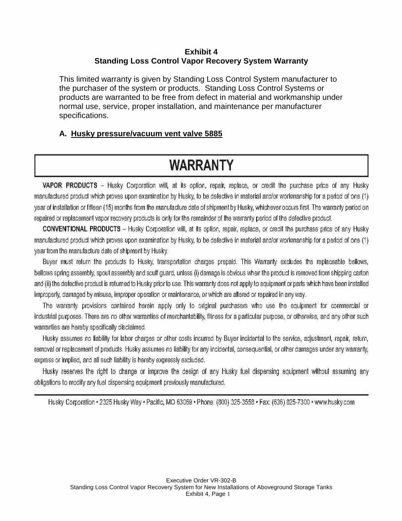
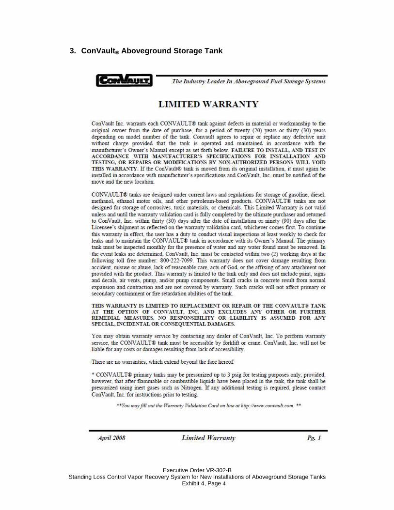
Exhibit 4 Standing Loss Control Vapor Recovery System Warrant y
This limited warranty is given by Standing Loss Control System manufacturer to the purchaser of the system or products. Standing Loss Control Systems or products are warranted to be free from defect in material and workmanship under normal use, service, proper installation, and maintenance per manufacturer specifications. A. Husky pressure/vacuum vent valve 5885
Executive Order VR-302-B Standing Loss Control Vapor Recovery System for New Installations of Aboveground Storage Tanks
Exhibit 4, Page 2
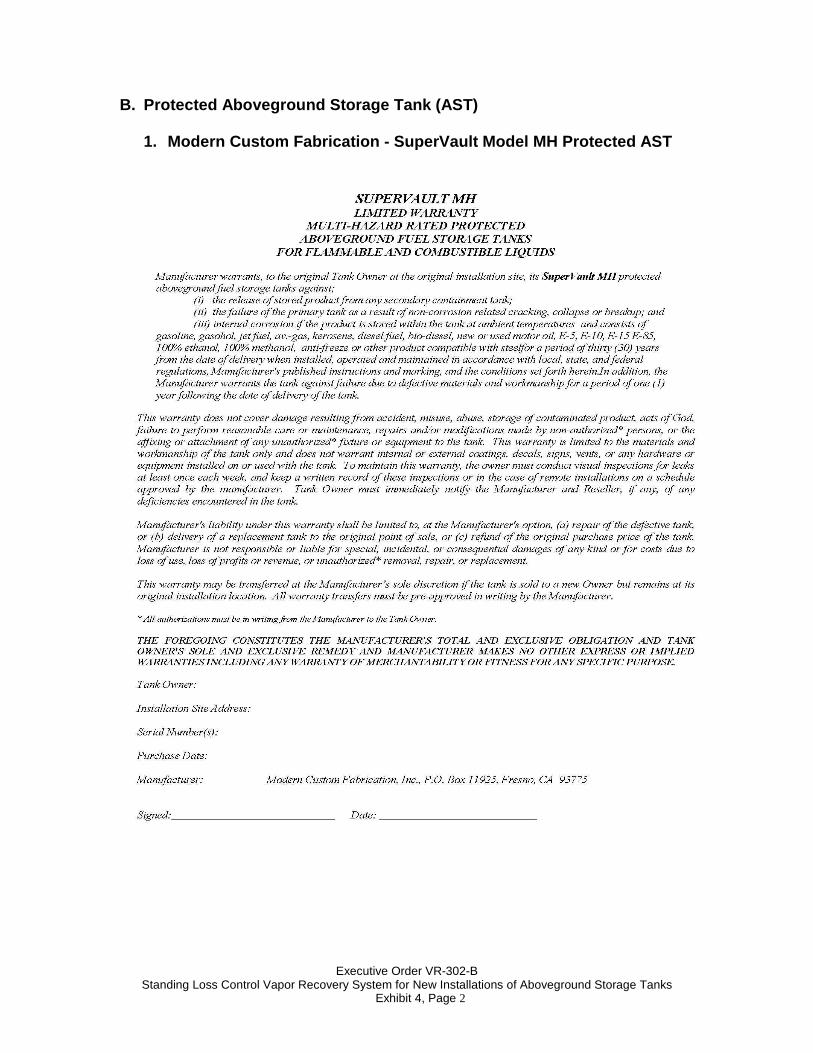
B. Protected Aboveground Storage Tank (AST)
1. Modern Custom Fabrication - SuperVault Model MH Protected AST
Executive Order VR-302-B Standing Loss Control Vapor Recovery System for New Installations of Aboveground Storage Tanks
Exhibit 4, Page 3
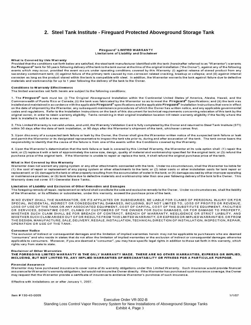
2. Steel Tank Institute - Fireguard Protected Above ground Storage Tank
Executive Order VR-302-B Standing Loss Control Vapor Recovery System for New Installations of Aboveground Storage Tanks
Exhibit 4, Page 4
3. ConVault ® Aboveground Storage Tank


![[XLS] · Web view1 302 2 302 3 302 4 302 5 302 6 363 7 363 8 302 9 302 10 307 11 302 12 302 13 223244 14 302 15 302 16 224 17 302 18 302 19 302 20 302 21 302 22 23 24 25 26 302 27](https://img.pdfslide.us/doc/110x75/5b00c3a37f8b9a952f8d6104/xls-view1-302-2-302-3-302-4-302-5-302-6-363-7-363-8-302-9-302-10-307-11-302-12.jpg)