Embed Size (px)
Citation preview

Morrison Installation, Operation and Maintenance Manual Executive Order VR-402-B page i
Installation, Operation and Maintenance Manual
For
Executive Order VR-402-B
Morrison Phase 1 Enhanced Vapor Recovery System
For Aboveground Storage Tanks

Morrison Installation, Operation and Maintenance Manual Executive Order VR-402-B page ii
NOTICE: The ARB Approved Installation, Operation and Maintenance Manual (IOM) for the VR-402 describes the tools, methods and skill levels required to install the Morrison Bros. Co. Phase I Enhanced Vapor Recovery (EVR) System for Aboveground Storage Tanks (AST). As specified in the individual IOM’s, only skilled technicians that are trained, certified and licensed by Morrison Bros. Co. (i.e. Morrison Certified Technicians) are able to perform installation, maintenance or repairs of components manufactured by Morrison Bros. Co. It is the responsibility of each Morrison Certified Technician to be familiar with the current requirements of state, federal, local codes and air district rules and regulations of installation and repair of gasoline dispensing equipment. It is also the responsibility of each Morrison Certified Technician to be aware of all the manuals, necessary safety precautions, and site requirements to assure a safe and trouble-free installation. To take online training or to confirm the status of a Morrison Certified Technician, please visit the Morrison Bros. Co’s website at www.morbros.com or contact: Morrison Customer Service Dept. Toll Free: 800-553-4840 General: 563-583-5701 Fax 563-583-5028 Email [email protected]

Morrison Installation, Operation and Maintenance Manual Executive Order VR-402-B page iii
Table of Contents Section 1: 244 Series Emergency Vents 1
Section 2: 515/516 Series Spill Containers 4
Section 3: 9095A Series Overfill Prevention Valves 7
Section 4: 419 Series Drop Tubes 24
Section 5: 927 Series Product Adaptors and 735DC Series Caps 26
Section 6: 928 Series Product Couplers 28
Section 7: 323 Series Vapor Adaptors and 323C Vapor Recovery Cap 30
Section 8: 818/918 Series Tank Gauges 32
Section 9: 305 Series Monitoring Cap and Adaptor 51
Section 10: 539 Series Drop Tube Diffuser 54
Appendix: 58
EVR Product Warranty Registration 59
Morrison Product Warranty 60
Morrison Venting Guide for Aboveground Storage Tanks 61
Tank Configuration Examples 74
Installation Specifications 78
Summary of Guidelines for Maintenance 79
EVR Installation Check List 83

Morrison Installation, Operation and Maintenance Manual Executive Order VR-402-B page 1
Section 1
244 Series Emergency Vents

Morrison Installation, Operation and Maintenance Manual Executive Order VR-402-B page 2
Morrison Fig. No. 244 Series Emergency Vent INSTALLATION, MAINTENANCE AND OPERATING INSTRUCTIONS
The 244 Series Emergency Vent is designed for use on aboveground storage tanks, as a code requirement that helps prevent tanks from becoming over-pressurized or rupturing if exposed to fire.
INSTALLATION: Mounting piping and connections to the tank must be fabricated so the emergency vent is in a vertical (plumb) position. Check interior of vent for foreign matter. O-ring surface should be clean and free of any dirt or particles. Verify cover is moving freely before and after placing into the system. Do not paint vent unless necessary. If painting, extreme caution must be exercised to make sure that the paint does not inhibit proper vent operation. Note: There should be no reduction of pipe size between the storage tank and the Fig. 244 Series Emergency Vent. Important: Install the included warning tag where it will be visible to the operator filling or unloading the tank that is fitted with this vent.
Threaded Connection: Use standard piping practices when installing vents with threaded ends. Apply a fuel resistant, non-hardening, anti-seize sealant (non-adhesive) to body threads. Morrison recommends thread sealant rather than Teflon® tape. Torque threaded joints as follows: 2” size 75-85 ft-lbs, 3”-4” size to 75-100 ft-lbs. Avoid over-torque, which may damage the vent.
Flange Connection: The vent must be visually centered with respect to the flange faces. A gasket must be placed between the flange faces. Flanged bolting should be tightened gradually in a crisscross pattern. Bolting should be tightened sufficiently to prevent leakage and loosening of the joint. Torque bolts to 50-55 ft-lbs. Avoid over-torque, which may damage the vent.
Failure to follow any or all of the warnings or instructions in this document could result in a hazardous product spill, which could result in property damage, environmental contamination, fire explosion, serious injury or death.
Warnings Fire Hazard – Death or serious injury could result from spilled liquids.
Install only on shop fabricated atmospheric tanks built and tested in accordance to industry standards such as UL142, NFPA 30 & 30A, and API 650.
Install in accordance with all applicable local, state, and federal laws.
244 Series vents only provide emergency pressure relief and must be used in conjunction with a normal vent or pressure vacuum vent.
244 Series vents as well as normal vents and pressure vacuum vents must be properly sized and selected for each specific tank application.
For your safety, it is important to follow local, state, federal and/or OSHA rules that apply to working inside, above, or around the storage tank and piping area. Use all personal protective equipment required for working in the specific environment.
Tanks could be under pressure. Vapors could be expelled from tank vents, piping, valves or fittings while performing installation. Vapors could catch fire or cause an explosion. Avoid sparks, open flame, or hot tools when working on vents.
Do not paint or cover vent. This will inhibit proper vent operation and may lead to personal injury/property damage.
244O--0115 PP EVR Rev. E
Page 1 of 2

Morrison Installation, Operation and Maintenance Manual Executive Order VR-402-B page 3
MAINTENANCE: Annual inspection, and immediate inspection during freezing conditions, by someone familiar with the proper operation of the storage tank vents, is required to insure venting devices are functioning properly before filling or unloading a tank. If painting, extreme caution must be exercised to make sure that the paint does not inhibit proper vent operation.
WARNINGS Fire Hazard – Death or serious injury could result from spilled liquids.
Clogged or restricted vents could cause damage to tanks and piping releasing liquids which could catch fire.
Dust, debris, freezing rain, freezing condensation or other contaminants could clog or restrict the vents.
In freezing conditions, inspect the vents immediately before filling or unloading a tank.
Follow your employer’s instructions for making sure vents are not clogged or restricted.
You must be trained to inspect the vents. Stop now if you have not been trained.
Do not fill or unload from a tank unless you are certain that the tank vents will operate correctly.
For your safety, it is important to follow local, state, federal and/or OSHA rules that apply to working inside, above, or around the storage tank and piping area. Use all personal protective equipment required for working in the specific environment.
Tanks could be under pressure. Vapors could be expelled from tank vents, piping, valves or fittings while performing maintenance. Vapors could catch fire or cause an explosion. Avoid sparks, open flame, or hot tools when working on vents.
Steps 1. Lift the cover of the vent all the way up and lower back down onto the body several times. The cover must move freely for the vent to work properly. 2. Replace the unit if sticking or binding occurs during step 1 above. 3. Inspect the vent, including the seal area, for dust, debris, snow or ice. Remove any that is found. 4. Inspect all vent components and surfaces for damage, corrosion or excessive wear. If
any is found replace the vent. 5. Inspect the vent warning tag located near the tank fill and offloading area. If the tag is damaged or difficult to read, contact Morrison Bros. Co. at (800) 553-4840 for a free
replacement tag. OPERATING INSTRUCTIONS: The emergency vent requires no assistance during operation. During operation the cover will not open until internal pressure in the tank reaches approximately 16 ounces per square inch pressure.
If you need any further information on applications, special configurations, approvals, etc. please consult Morrison’s catalog, contact Morrison, or visit our website at www.morbros.com.
WARRANTY: If you believe this vent has a defect due to material or workmanship, please contact
Morrison for a return authorization. All products are thoroughly tested before shipment and meet all applicable performance standards and specifications. Only material found to be defective in manufacture will be replaced or repaired at our discretion. Claims must be made within one year from the date of installation, and Morrison Bros. Co. will not allow claims for labor or consequential damage resulting from purchase, installation or misapplication of the product. The warranty registration information must be provided to the end user.
Dubuque, Iowa 52001
800.553.4840 • 563.583.5028 Fax •
www.morbros.com 244O--0115 PP EVR Rev. E
Page 2 of 2

Morrison Installation, Operation and Maintenance Manual Executive Order VR-402-B page 4
Section 2
515 Series Remote Spill Containers
516 Series Direct Fill Spill Containers

Morrison Installation, Operation and Maintenance Manual Executive Order VR-402-B page 5
Morrison Fig. No. 515/516 Series Spill Container INSTALLATION, MAINTENANCE AND OPERATING INSTRUCTIONS
FIG. NO. 515 INSTALLATION: Bolt base to stable footing that will not rise or sink from outdoor
conditions. Adjust height of box so ports on rear of box align with system piping. Use standard piping practices when installing fittings with threaded ends. Apply a fuel resistant, non-hardening, anti-seize sealant (non adhesive) to fitting threads. Morrison recommends thread sealant rather than Teflon® tape. Torque threaded joints as follows: 2” size 75-85 ft-lbs, 3”-4” size to 75-100 ft-lbs. Avoid over-torque, which may damage the fittings. Adjoining piping must be properly supported and positioned so minimal piping stresses are transmitted to the box during or after installation. The spill container is not made to secure the weight of the piping structure. Bolt flanges to rear of spill container box. Flanged bolting should be tightened gradually in a crisscross pattern. Bolting should be tightened sufficiently to prevent loosening of the joint. Thread pipes from the system into companion flanges. Mount fittings internal to box to the inside face of the companion flange. It is highly recommended that the whole installation be tested before being released for use.
FIG. NO. 516 INSTALLATION: Apply a fuel resistant, non-hardening, anti-seize sealant (non-
adhesive) to pipe threads. Morrison recommends thread sealant rather than Teflon® tape. Torque threaded joint to 75-100 ft-lbs. Avoid over-torque, which may damage the fittings. Thread spill container on to tank. Mount fittings internal to container. Avoid over-torque, which may damage the fittings. It is highly recommended that the whole assembly be tested before being released for use.
Failure to follow any or all of the warnings may render the spill container nonfunctional and could result in a hazardous product spill, which may result in property damage, environmental contamination, fire, explosion, injury or death.
WARNINGS Fire Hazard - Death or serious injury could result from spilled liquids.
Any modification to this spill container other than stated in these installation instructions will void the product warranty.
Install in accordance with all applicable local, state, and federal laws.
For your safety, it is important to follow local, state, federal and/or OSHA rules that apply to working inside, above, or around the storage tank and piping area. Use all personal protective equipment required for working in the specific environment.
Tanks could be under pressure. Vapors could be expelled from tank vents, piping, valves or fittings while performing installation. Vapors could catch fire or cause an explosion. Avoid sparks, open flame, or hot tools when working on spill containers.
Dubuque, Iowa 52001
800.553.4840 • 563.583.5028 Fax •
www.morbros.com 515---0252 PP EVR Rev. D
Page 1 of 2

Morrison Installation, Operation and Maintenance Manual Executive Order VR-402-B page 6 MAINTENANCE: Ensure product is properly installed. Observe the container to assure proper performance. Visually inspect exterior and interior of container on a regular basis, or at least once a year to ensure the product is not worn or damaged to affect the functionality of the parts. Clean and remove any dirt, debris or spilled product from the spill container after each delivery. Product should not be drained to the ground or into the atmosphere. All hazardous materials need to be properly disposed according to local, state, or federal regulations. Additionally for the Fig. No.515, place a small amount of water in the spill container to verify the drain valve is holding liquid in the box. Drain water.
WARNINGS Fire Hazard - Death or serious injury could result from spilled liquids.
You must be trained to maintain this spill container Stop now if you have not been trained
For your safety, it is important to follow local, state, federal and/or OSHA rules that apply to working inside, above, or around the storage tank and piping area. Use all personal protective equipment required for working in the specific environment.
Tanks could be under pressure. Vapors could be expelled from tank vents, piping, valves or fittings while performing installation. Vapors could catch fire or cause an explosion. Avoid sparks, open flame, or hot tools when working on spill containers.
OPERATING INSTRUCTIONS: The tank operator must ensure that all federal, state and local codes are met during the filling of this tank. Only experienced operators familiar with tank filling procedures should be allowed to fill or transfer product in this system. It is the responsibility of the operator to continuously monitor the tank filling process and take all necessary precautions to prevent any spill. The operator shall ensure that the delivery hose from the tank’s fill pipe is not disconnected until the hose has been drained completely. During unloading operations, the operator must remain in constant view of the transfer nozzle and fill pipe, and be in constant attendance at the discharge control valve. To evacuate spilled product from containment unit, bailing or mopping may be necessary. If unit is equipped with a drain valve, place a separate container under valve and open valve to drain contents. Product should not be drained to the ground or into the atmosphere. All hazardous materials need to be properly disposed according to local, state, or federal regulations. If you need any further information on applications, special configurations, approvals, etc. please consult Morrison’s catalog, contact Morrison, or visit our website at www.morbros.com.
WARRANTY: If you believe this vent has a defect due to material or workmanship, please contact
Morrison for a return authorization. All products are thoroughly tested before shipment and meet all applicable performance standards and specifications. Only material found to be defective in manufacture will be replaced or repaired at our discretion. Claims must be made within one year from the date of installation, and Morrison Bros. Co. will not allow claims for labor or consequential damage resulting from purchase, installation or misapplication of the product. The warranty registration information must be provided to the end user.
Dubuque, Iowa 52001
800.553.4840 • 563.583.5028 Fax •
www.morbros.com 515---0252 PP EVR Rev. D
Page 2 of 2
Morrison Installation, Operation and Maintenance Manual Executive Order VR-402-B page 7
Section 3
9095A Series Overfill Prevention Valves

Morrison Installation, Operation and Maintenance Manual Executive Order VR-402-B page 8

Morrison Installation, Operation and Maintenance Manual Executive Order VR-402-B page 9

Morrison Installation, Operation and Maintenance Manual Executive Order VR-402-B page 10

Morrison Installation, Operation and Maintenance Manual Executive Order VR-402-B page 11

Morrison Installation, Operation and Maintenance Manual Executive Order VR-402-B page 12

Morrison Installation, Operation and Maintenance Manual Executive Order VR-402-B page 13

Morrison Installation, Operation and Maintenance Manual Executive Order VR-402-B page 14

Morrison Installation, Operation and Maintenance Manual Executive Order VR-402-B page 15

Morrison Installation, Operation and Maintenance Manual Executive Order VR-402-B page 16

Morrison Installation, Operation and Maintenance Manual Executive Order VR-402-B page 17

Morrison Installation, Operation and Maintenance Manual Executive Order VR-402-B page 18

Morrison Installation, Operation and Maintenance Manual Executive Order VR-402-B page 19

Morrison Installation, Operation and Maintenance Manual Executive Order VR-402-B page 20

Morrison Installation, Operation and Maintenance Manual Executive Order VR-402-B page 21

Morrison Installation, Operation and Maintenance Manual Executive Order VR-402-B page 22

Morrison Installation, Operation and Maintenance Manual Executive Order VR-402-B page 23

Morrison Installation, Operation and Maintenance Manual Executive Order VR-402-B page 24
Section 4
419 Series Drop Tube

Morrison Installation, Operation and Maintenance Manual Executive Order VR-402-B page 25
1. Check drop tube for any defects or damage that may have occurred in shipping. 2. Measure the distance from the top of the riser pipe to the bottom of the tank. 3. Using the Drop Tube Length Calculator at below, Calculate the length of the drop tube and cut
the end of the drop tube at a 45 degree angle. (Cut end of drop tube should not be more than 6 inches from bottom of tank.)
4. Place drop tube into riser pipe.
Morrison Fig. No. 419 Drop Tube INSTALLATION, MAINTENANCE AND OPERATING INSTRUCTIONS
INSTALLATION:
Failure to follow any or all of the warnings may render the drop tube nonfunctional and could result in a hazardous product spill, which may result in property damage, environmental contamination, fire, explosion, injury or death.
WARNINGS Fire Hazard - Death or serious injury could result from spilled liquids.
Any modification to this drop tube other than stated in these installation instructions will void the product warranty.
Install in accordance with all applicable local, state, and federal laws.
For your safety, it is important to follow local, state, federal and/or OSHA rules that apply to working inside, above, or around the storage tank and piping area. Use all personal protective equipment required for working in the specific environment.
Tanks could be under pressure. Vapors could be expelled from tank vents, piping, valves or fittings while performing installation. Vapors could catch fire or cause an explosion. Avoid sparks, open flame, or hot tools when working on drop tubes.
MAINTENANCE: No maintenance is required for this product, but local codes may require specific procedures. It should be verified during installation that the bottom of the drop tube is at the proper distance from the bottom of the tank.
WARNINGS
Fire Hazard - Death or serious injury could result from spilled liquids.
You must be trained to maintain this drop tube Stop now if you have not been trained
Tanks could be under pressure. Vapors could be expelled from tank vents, piping, valves or fittings while performing installation. Vapors could catch fire or cause an explosion. Avoid sparks, open flame, or hot tools when working on drop tubes.
OPERATING INSTRUCTIONS: The drop tube does not require any assistance during operation.
If you need any further information on applications, special configurations, approvals, etc. please consult Morrison’s catalog, contact Morrison, or visit our website at www.morbros.com. WARRANTY: If you believe this vent has a defect due to material or workmanship, please contact Morrison for a return
authorization. All products are thoroughly tested before shipment and meet all applicable performance standards and specifications. Only material found to be defective in manufacture will be replaced or repaired at our discretion. Claims must be made within one year from the date of installation, and Morrison Bros. Co. will not allow claims for labor or consequential damage resulting from purchase, installation or misapplication of the product. The warranty registration information must be provided to the end user.
Dubuque, Iowa 52001
800.553.4840 • 563.583.5028 Fax
[email protected]• www.morbros.com 419---0103 PP EVR Rev. D
Drop Tube Length Calculator ____________ = Measured distance from top of riser pipe to bottom of tank. - 6 inches = . = Required length of drop tube.

Morrison Installation, Operation and Maintenance Manual Executive Order VR-402-B page 26
Section 5
927 Series Product Adaptor And
735DC Series Product Cap

Morrison Installation, Operation and Maintenance Manual Executive Order VR-402-B page 27
Morrison Fig. No. 735DC/927 Series Product Cap & Adaptor INSTALLATION, MAINTENANCE AND OPERATING INSTRUCTIONS
INSTALLATION: Adaptor: Apply a fuel resistant, non-hardening, anti-seize sealant (non adhesive) to body threads. Morrison recommends thread sealant rather than Teflon® tape. Thread adaptor on to riser pipe until handtight then tighten per one of the following specifications. Wrench Makeup Specifications
Wrench Makeup*
SIZE (Number of Turns)
2” NPT Threads 3.25
3” NPT Threads 2
4” NPT Threads 2.12
* - All sizes should have handtight engagement before Wrench Makeup is applied. A tolerance of plus or minus one turn is allowed. This information is to be used as guide only. The number of turns may vary depending on the quality of thread form. Torque Specifications
SIZE Torque
2” NPT Threads 75-85 ft-lb
3” NPT Threads 75-100 ft-lb
4” NPT Threads 23-26 ft-lb
* - No special tools required. Torque value could be verified by offset chain wrench and torque wrench. The Torque Specification method is required rather than Wrench Makeup Specification method for components installed in California,.
Cap: Set cap on adaptor. Push lever arms inward to body to secure and seal cap to the adaptor.
Failure to follow any or all of the warnings may render the cap and adaptor nonfunctional and could result in a hazardous product spill, which may result in property damage, environmental contamination, fire, explosion, injury or death.
WARNINGS Fire Hazard - Death or serious injury could result from spilled liquids.
Any modification to this cap and adaptor other than stated in these installation instructions will void the product warranty.
Install in accordance with all applicable local, state, and federal laws.
For your safety, it is important to follow local, state, federal and/or OSHA rules that apply to working inside, above, or around the storage tank and piping area. Use all personal protective equipment required for working in the specific environment.
Tanks could be under pressure. Vapors could be expelled from tank vents, piping, valves or fittings while performing installation. Vapors could catch fire or cause an explosion. Avoid sparks, open flame, or hot tools when working on caps and adaptors.
MAINTENANCE: Ensure product is properly installed. Visually inspect both cap and adaptor on a regular basis, or at least once a year to ensure the product is not worn or damaged to affect the functionality of the parts. Also ensure the gaskets on the cap and adaptor are present and sealing adequately. Wipe seals clean of any dirt or particles if necessary. The adaptor will require that the poppet be manually pushed in to inspect the whole seal.
WARNING: Tank may be under pressure. Product may be expelled out from the port opening as the adaptor poppet is depressed.
OPERATING INSTRUCTIONS: Pull out lever arms to remove cap. Push in lever arms to seal cap.
If you need any further information on applications, special configurations, approvals, etc. please consult Morrison’s catalog, contact Morrison, or visit our website at www.morbros.com.
WARRANTY: If you believe this vent has a defect due to material or workmanship, please contact Morrison for a
return authorization. All products are thoroughly tested before shipment and meet all applicable performance standards and specifications. Only material found to be defective in manufacture will be replaced or repaired at our discretion. Claims must be made within one year from the date of installation, and Morrison Bros. Co. will not allow claims for labor or consequential damage resulting from purchase, installation or misapplication of the product. The warranty registration information must be provided to the end user.
Dubuque, Iowa 52001
800.553.4840 • 563.583.5028 Fax •
www.morbros.com 927---0211 PP EVR Rev. E

Morrison Installation, Operation and Maintenance Manual Executive Order VR-402-B page 28
Section 6
928 Series Product Coupler

Morrison Installation, Operation and Maintenance Manual Executive Order VR-402-B page 29
Morrison Fig. No. 928 Series Dry Disconnect Coupler INSTALLATION, MAINTENANCE AND OPERATING INSTRUCTIONS INSTALLATION: 1. Apply a fuel resistant, non-hardening, anti-seize sealant (non adhesive) to hose end or pipe threads. Morrison recommends thread sealant rather than Teflon® tape. 2. Thread coupler on to hose end or pipe.
OPERATING INSTRUCTIONS: 1. Inspect the coupler gasket and adaptor face to be smooth and free of contamination. 2. Attach the female coupler over the mating male adaptor until the gasket in the couple makes contact with the front face of the adaptor. 3. The connection is secured by pushing the lever arms in toward the body simultaneously. Lever arms must be positioned parallel with the coupler body to fully lock.
WARNING: Care must be taken to insure proper connection and a positive seal. Improperly fitted or applied connections can result in a serious accident or product spillage. Under no circumstances shall the pressure rating of the couplings be exceeded. Failure to follow any or all of the warnings may render the coupler nonfunctional and could result in a hazardous product spill, which may result in property damage, environmental contamination, fire, explosion, injury or death.
WARNINGS
Fire Hazard - Death or serious injury could result from spilled liquids. Any modification to this coupler other than stated in these installation instructions will void the product warranty.
Install in accordance with all applicable local, state, and federal laws.
Follow local regulations for (un)loading product.
Coupler to be used for its designed purpose only.
For your safety, it is important to follow local, state, federal and/or OSHA rules that apply to working inside, above, or around the storage tank and piping area. Use all personal protective equipment required for working in the specific environment.
Product flow may result in static electricity; therefore grounding of equipment is required.
Tanks could be under pressure. Vapors could be expelled from tank adaptor, vents, piping, valves or fittings while performing (un)loading. Vapors could catch fire or cause an explosion. Avoid sparks, open flame, or hot tools when working on couplers.
MAINTENANCE: Ensure product is properly installed. Visually inspect coupler on a regular basis, or at least once
a year to ensure the product is not worn or damaged to affect the functionality of the parts. Also ensure the gaskets on coupler are present and sealing adequately. Wipe seals clean of any dirt or particles if necessary. Inspect lever arms and pins for excessive wear or damage. Replace any parts that are deteriorated, worn, or damaged.
WARNING: Tank may be under pressure. Vapors may be expelled out from the mating adaptor as the coupler is attached or removed
If you need any further information on applications, special configurations, approvals, etc. please consult Morrison’s catalog, contact Morrison, or visit our website at www.morbros.com. WARRANTY: If you believe this vent has a defect due to material or workmanship, please contact Morrison for a
return authorization. All products are thoroughly tested before shipment and meet all applicable performance standards and specifications. Only material found to be defective in manufacture will be replaced or repaired at our discretion. Claims must be made within one year from the date of installation, and Morrison Bros. Co. will not allow claims for labor or consequential damage resulting from purchase, installation or misapplication of the product. The warranty registration information must be provided to the end user.
Dubuque, Iowa 52001 800.553.4840 • 563.583.5028 Fax •
www.morbros.com 928---0309 PP EVR Rev. C

Morrison Installation, Operation and Maintenance Manual Executive Order VR-402-B page 30
Section 7
323 Series Vapor Recovery Adaptor And
323C Vapor Recovery Cap

Morrison Installation, Operation and Maintenance Manual Executive Order VR-402-B page 31
Morrison Fig. No. 323C/323 Series Vapor Cap & Adaptor INSTALLATION, MAINTENANCE AND OPERATING INSTRUCTIONS
INSTALLATION: Adaptor: 1. Apply a fuel resistant, non-hardening, anti-seize sealant (non adhesive) to body threads. Morrison recommends thread sealant rather than Teflon® tape. 2. Thread adaptor on to riser pipe until handtight then tighten per on of the following specifications. Wrench Makeup Specifications
Wrench Makeup*
SIZE (Number of Turns)
3” NPT Threads 2
4” NPT Threads 2.12
* - All sizes should have handtight engagement before Wrench Makeup is applied. A tolerance of plus or minus one turn is allowed. This information is to be used as guide only. The number of turns may vary depending on the quality of thread form. Torque Specifications
SIZE Torque
3” NPT Threads 75-100 ft-lb
4” NPT Threads 23-26 ft-lb
* - No special tools required. Torque value could be verified by offset chain wrench and torque wrench. The Torque Specification method is required rather than Wrench Makeup Specification method for components installed in California,.
Cap: Set cap on adaptor. Push down lever arms until they snap down securing cap to the adaptor.
Failure to follow any or all of the warnings may render the cap and adaptor nonfunctional and could result in a hazardous product spill, which may result in property damage, environmental contamination, fire, explosion, injury or death.
WARNINGS Fire Hazard - Death or serious injury could result from spilled liquids.
Any modification to this cap and adaptor other than stated in these installation instructions will void the product warranty.
Install in accordance with all applicable local, state, and federal laws.
For your safety, it is important to follow local, state, federal and/or OSHA rules that apply to working inside, above, or around the storage tank and piping area. Use all personal protective equipment required for working in the specific environment.
Tanks could be under pressure. Vapors could be expelled from tank vents, piping, valves or fittings while performing installation. Vapors could catch fire or cause an explosion. Avoid sparks, open flame, or hot tools when working on caps and adaptors.
MAINTENANCE: Ensure product is properly installed. Visually inspect both cap and adaptor on a regular basis, or at least once a year to ensure the product is not worn or damaged to affect the functionality of the parts. Also ensure the gaskets on the cap and adaptor are present and sealing adequately. Wipe seals clean of any dirt or particles if necessary. The adaptor will require that the poppet be manually pushed in to inspect the whole seal.
WARNING: Tank may be under pressure. Vapors may be expelled out from the port opening as the adaptor poppet is depressed.
OPERATING INSTRUCTIONS: Pull up on cap ring to remove cap. Push down on lever arms to seal cap.
If you need any further information on applications, special configurations, approvals, etc. please consult Morrison’s catalog, contact Morrison, or visit our website at www.morbros.com. WARRANTY: If you believe this vent has a defect due to material or workmanship, please contact Morrison for a
return authorization. All products are thoroughly tested before shipment and meet all applicable performance standards and specifications. Only material found to be defective in manufacture will be replaced or repaired at our discretion. Claims must be made within one year from the date of installation, and Morrison Bros. Co. will not allow claims for labor or consequential damage resulting from purchase, installation or misapplication of the product. The warranty registration information must be provided to the end user.
Dubuque, Iowa 52001 800.553.4840 • 563.583.5028 Fax •
www.morbros.com 323---0309 PP EVR Rev. E

Morrison Installation, Operation and Maintenance Manual Executive Order VR-402-B page 32
Section 8
818/918 Series Tank Gauge

Morrison Installation, Operation and Maintenance Manual Executive Order VR-402-B page 33

Morrison Installation, Operation and Maintenance Manual Executive Order VR-402-B page 34

Morrison Installation, Operation and Maintenance Manual Executive Order VR-402-B page 35

Morrison Installation, Operation and Maintenance Manual Executive Order VR-402-B page 36

Morrison Installation, Operation and Maintenance Manual Executive Order VR-402-B page 37
Morrison Installation, Operation and Maintenance Manual Executive Order VR-402-B page 38

Morrison Installation, Operation and Maintenance Manual Executive Order VR-402-B page 39
Morrison Installation, Operation and Maintenance Manual Executive Order VR-402-B page 40

Morrison Installation, Operation and Maintenance Manual Executive Order VR-402-B page 41

Morrison Installation, Operation and Maintenance Manual Executive Order VR-402-B page 42

Morrison Installation, Operation and Maintenance Manual Executive Order VR-402-B page 43
Morrison Installation, Operation and Maintenance Manual Executive Order VR-402-B page 44

Morrison Installation, Operation and Maintenance Manual Executive Order VR-402-B page 45

Morrison Installation, Operation and Maintenance Manual Executive Order VR-402-B page 46

Morrison Installation, Operation and Maintenance Manual Executive Order VR-402-B page 47

Morrison Installation, Operation and Maintenance Manual Executive Order VR-402-B page 48

Morrison Installation, Operation and Maintenance Manual Executive Order VR-402-B page 49
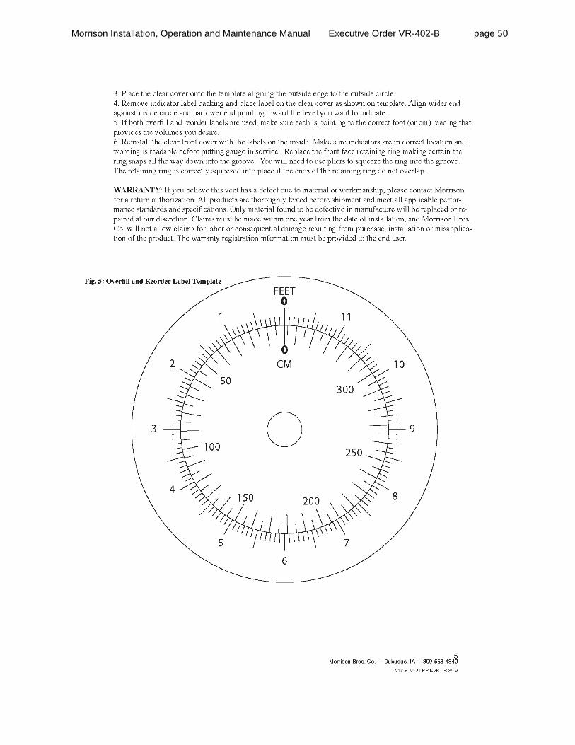
Morrison Installation, Operation and Maintenance Manual Executive Order VR-402-B page 50

Morrison Installation, Operation and Maintenance Manual Executive Order VR-402-B page 51
Section 9
305 Series Monitoring Cap and Adaptor

Morrison Installation, Operation and Maintenance Manual Executive Order VR-402-B page 52
Morrison 2” Fig. No. 305 Series Vapor Cap & Adaptor INSTALLATION, MAINTENANCE AND OPERATING INSTRUCTIONS INSTALLATION: Adaptor: 1. Apply a fuel resistant, non-hardening, anti-seize sealant (non adhesive) to body threads. Morrison recommends thread sealant rather than Teflon® tape. 2. Make sure the end of riser pipe is not sharp or it may cut and damage body gasket. File end
of riser pipe smooth before installing riser pipe into tank to prevent filings entering tank. 3. Thread adaptor on to riser pipe until handtight then tighten per one of the following specifications. Wrench Makeup Specifications
Wrench Makeup*
SIZE (Number of Turns)
2” NPT Threads 3.25
* - All sizes should have handtight engagement before Wrench Makeup is applied. A tolerance of plus or minus one turn is allowed. This information is to be used as guide only. The number of turns may vary depending on the quality of thread form. Torque Specifications
SIZE Torque
2” NPT Threads 23-26 ft-lb
* - No special tools required. Torque value could be verified by offset chain wrench and torque wrench. The Torque Specification method is required rather than Wrench Makeup Specification method for components installed in California,.
Cap: Set cap on adaptor. Push in lever arm securing cap to the adaptor. Failure to follow any or all of the warnings may render the cap and adaptor nonfunctional and could result in a hazardous product spill, which may result in property damage, environmental contamination, fire, explosion, injury or death.
WARNINGS Fire Hazard - Death or serious injury could result from spilled liquids.
Any modification to this cap and adaptor other than stated in these installation instructions will void the product warranty.
Install in accordance with all applicable local, state, and federal laws.
For your safety, it is important to follow local, state, federal and/or OSHA rules that apply to working inside, above, or around the storage tank and piping area. Use all personal protective equipment required for working in the specific environment.
Tanks could be under pressure. Vapors could be expelled from tank vents, piping, valves or fittings while performing installation. Vapors could catch fire or cause an explosion. Avoid sparks, open flame, or hot tools when working on valves.
MAINTENANCE: Ensure product is properly installed. Visually inspect both cap and adaptor on a regular basis, or at least once a year to ensure the product is not worn or damaged to affect the functionality of the parts. Also ensure the gaskets on the cap and adaptor are present and sealing adequately. Wipe seals clean of any dirt or particles if necessary. WARNING: Tank may be under pressure. Vapors may be expelled out from the port opening as the cap is removed. Grip cap firmly as it is removed from the adaptor. OPERATING INSTRUCTIONS: Push out on cap lever arm to remove cap. Push in on cap lever arm to seal cap. If you need any further information on applications, special configurations, approvals, etc. please consult Morrison’s catalog, contact Morrison, or visit our website at www.morbros.com. WARRANTY: If you believe this vent has a defect due to material or workmanship, please contact Morrison for a
return authorization. All products are thoroughly tested before shipment and meet all applicable performance standards and specifications. Only material found to be defective in manufacture will be replaced or repaired at our discretion. Claims must be made within one year from the date of installation, and Morrison Bros. Co. will not allow claims for labor or consequential damage resulting from purchase, installation or misapplication of the product. The warranty registration information must be provided to the end user.
Dubuque, Iowa 52001 800.553.4840 • 563.583.5028 Fax •
www.morbros.com 305XPA2331 PP EVR Rev. E

Morrison Installation, Operation and Maintenance Manual Executive Order VR-402-B page 53
Morrison 4” Fig. No. 305 Series Tank Monitoring Cap & Adaptor INSTALLATION, MAINTENANCE AND OPERATING INSTRUCTIONS INSTALLATION:
Adaptor: 1. Apply a fuel resistant, non-hardening, anti-seize sealant (non adhesive) to body threads. Morrison recommends thread sealant rather than Teflon® tape. 2. Make sure the end of riser pipe is not sharp or it may cut and damage body gasket. File end of riser pipe smooth before installing riser pipe into tank to prevent filings entering tank. 3. Thread adaptor on to riser pipe until handtight then
tighten per one of the following specifications. Wrench Makeup Specifications
* - All sizes should have handtight engagement before Wrench Makeup is applied. A tolerance of plus or minus one turn is allowed. This information is to be used as guide only. The number of turns may vary depending on the quality of thread form. Torque Specifications
SIZE Torque
4” NPT Threads 23-26 ft-lb
* - No special tools required. Torque value could be verified by offset chain wrench and torque wrench. The Torque Specification method is required rather than Wrench Makeup Specification method for components installed in California,.
Cap: 1. Apply a fuel resistant, non-hardening, anti-seize sealant (non-adhesive) to cable connector threads. Follow manufacturer’s instructions for installation of monitoring system. 2. Set cap on adaptor. Push down lever arms securing cap to the adaptor. Failure to follow any or all of the warnings may render the cap and adaptor nonfunctional and could result in a hazardous product spill, which may result in property damage, environmental contamination, fire, explosion, injury or death. WARNINGS
Fire Hazard - Death or serious injury could result from spilled liquids.
Any modification to this cap and adaptor other than stated in these installation instructions will void the product warranty.
Install in accordance with all applicable local, state, and federal laws.
For your safety, it is important to follow local, state, federal and/or OSHA rules that apply to working inside, above, or around the storage tank and piping area. Use all personal protective equipment required for working in the specific environment.
Tanks could be under pressure. Vapors could be expelled from tank vents, piping, valves or fittings while performing installation. Vapors could catch fire or cause an explosion. Avoid sparks, open flame, or hot
tools when working on valves. MAINTENANCE: Ensure product is properly installed. Visually inspect both cap and adaptor on a regular basis, or at
least once a year to ensure the product is not worn or damaged to affect the functionality of the parts. Also ensure the gaskets on the cap and adaptor are present and sealing adequately. Wipe seals clean of any dirt or particles if necessary. WARNING: Tank may be under pressure. Vapors may be expelled out from the port opening as the cap is removed.
Grip cap firmly as it is removed from the adaptor.
OPERATING INSTRUCTIONS: Pull up on cap ring to remove cap. Push down on lever arms to seal cap. If you need any further information on applications, special configurations, approvals, etc. please consult Morrison’s catalog, contact Morrison, or visit our website at www.morbros.com. WARRANTY: If you believe this vent has a defect due to material or workmanship, please contact Morrison for a return authorization. All products are thoroughly tested before shipment and meet all applicable performance standards and specifications. Only material found to be defective in manufacture will be replaced or repaired at our discretion. Claims must be made within one year from the date of installation, and Morrison Bros. Co. will not allow claims for labor or consequential damage resulting from purchase, installation or misapplication of the product. The warranty registration information must be provided to the end user.
Dubuque, Iowa 52001 800.553.4840 • 563.583.5028 Fax •
www.morbros.com 305XPA113121 EVR Rev. E
Wrench Makeup*
SIZE (Number of Turns)
4” NPT Threads 2.12

Morrison Installation, Operation and Maintenance Manual Executive Order VR-402-B page 54
Section 10
539 Series Drop Tube Diffuser

Morrison Installation, Operation and Maintenance Manual Executive Order VR-402-B page 55
Morrison 2” Fig. No. 539AS Series Drop Tube Diffuser INSTALLATION, MAINTENANCE AND OPERATING INSTRUCTIONS INSTALLATION: 1. The diffuser is made for an aluminum drop tube
with an outside diameter of no more than 2”. 2. Measure the distance from the top of the riser
pipe to the bottom of the tank. 3. Using the Drop Tube Length Calculator at the
right, calculate the length of the drop tube and cut the end of the drop tube square. (Cut end of drop tube should be 6 inches from bottom of tank.)
4. Place the attached Hole Location Template onto the tube so the bottom edge of the sheet is flush with the bottom edge of the tube.
5. Using the template, lightly center punch hole locations and drill through the tube with a 7/32” drill.
6. Remove the template from the drop tube. 7. Place nut clips on tube and align with holes in tube.
8. Place diffuser on tube, align holes and secure with enclosed screws.
Failure to follow any or all of the warnings may render the diffuser nonfunctional and could result in a hazardous product spill, which may result in property damage, environmental contamination, fire, explosion, injury or death.
WARNINGS Fire Hazard - Death or serious injury could result from spilled liquids.
Any modification to this diffuser other than stated in these installation instructions will void the product warranty.
Install in accordance with all applicable local, state, and federal laws.
For your safety, it is important to follow local, state, federal and/or OSHA rules that apply to working inside, above, or around the storage tank and piping area. Use all personal protective equipment required for working in the specific environment.
Tanks could be under pressure. Vapors could be expelled from tank vents, piping, valves or fittings while performing installation. Vapors could catch fire or cause an explosion. Avoid sparks, open flame, or hot tools when working on valves.
You must be trained to maintain this diffuser Stop now if you have not been trained
MAINTENANCE: None required. OPERATING INSTRUCTIONS: The diffuser does not require any assistance during operation.
If you need any further information on applications, special configurations, approvals, etc. please consult Morrison’s catalog, contact Morrison, or visit our website at www.morbros.com. WARRANTY: If you believe this vent has a defect due to material or workmanship, please contact Morrison for a return
authorization. All products are thoroughly tested before shipment and meet all applicable performance standards and specifications. Only material found to be defective in manufacture will be replaced or repaired at our discretion. Claims must be made within one year from the date of installation, and Morrison Bros. Co. will not allow claims for labor or consequential damage resulting from purchase, installation or misapplication of the product. The warranty registration information must be provided to the end user.
Dubuque, Iowa 52001
800.553.4840 • 563.583.5028 Fax •
www.morbros.com 539AS-0208 PP EVR Rev. C
2” Hole Location Template 539AS-0208 PP EVR Rev. B
Drill Hole (3x)
(Align this edge with bottom of tube)
Drop Tube Length Calculator ____________ = Measured distance from top of riser pipe to bottom of tank. - 6 inches = . = = Required length of drop tube.

Morrison Installation, Operation and Maintenance Manual Executive Order VR-402-B page 56
Morrison 3” Fig. No. 539AS Series Drop Tube Diffuser INSTALLATION, MAINTENANCE AND OPERATING INSTRUCTIONS INSTALLATION: 9. The diffuser is made for an aluminum drop tube with an
outside diameter of no more than 3”. 10. Measure the distance from the top of the riser
pipe to the bottom of the tank. 11. Using the Drop Tube Length Calculator at the
right, calculate the length of the drop tube and cut the end of the drop tube square. (Cut end of drop tube should be 6 inches from bottom of tank.)
12. Place the attached Hole Location Template onto the tube so the bottom edge of the sheet is flush with the bottom edge of the tube.
13. Using the template, lightly center punch hole locations and drill through the tube with a 7/32” drill.
14. Remove the template from the drop tube. 15. Place nut clips on tube and align with holes in tube. 16. Place diffuser on tube, align holes and secure with enclosed screws.
Failure to follow any or all of the warnings may render the diffuser nonfunctional and could result in a hazardous product spill, which may result in property damage, environmental contamination, fire, explosion, injury or death.
WARNINGS Fire Hazard - Death or serious injury could result from spilled liquids.
Any modification to this diffuser other than stated in these installation instructions will void the product warranty.
Install in accordance with all applicable local, state, and federal laws.
For your safety, it is important to follow local, state, federal and/or OSHA rules that apply to working inside, above, or around the storage tank and piping area. Use all personal protective equipment required for working in the specific environment.
Tanks could be under pressure. Vapors could be expelled from tank vents, piping, valves or fittings while performing installation. Vapors could catch fire or cause an explosion. Avoid sparks, open flame, or hot tools when working on valves.
You must be trained to maintain this diffuser Stop now if you have not been trained
MAINTENANCE: None required. OPERATING INSTRUCTIONS: The diffuser does not require any assistance during operation.
If you need any further information on applications, special configurations, approvals, etc. please consult Morrison’s catalog, contact Morrison, or visit our website at www.morbros.com. WARRANTY: If you believe this vent has a defect due to material or workmanship, please contact Morrison for a return
authorization. All products are thoroughly tested before shipment and meet all applicable performance standards and specifications. Only material found to be defective in manufacture will be replaced or repaired at our discretion. Claims must be made within one year from the date of installation, and Morrison Bros. Co. will not allow claims for labor or consequential damage resulting from purchase, installation or misapplication of the product. The warranty registration information must be provided to the end user.
Dubuque, Iowa 52001
800.553.4840 • 563.583.5028 Fax •
www.morbros.com 539AS-0309 PP EVR Rev. C
3” Hole Location Template 539AS-0309 PP EVR Rev. B
Drop Tube Length Calculator ____________ = Measured distance from top of riser pipe to bottom of tank. - 6 inches = . = = Required length of drop tube.
Drill Hole (3x)
(Align this edge with bottom of tube)

Morrison Installation, Operation and Maintenance Manual Executive Order VR-402-B page 57
Morrison Fig. No. 539AT Series Drop Tube Diffuser INSTALLATION, MAINTENANCE AND OPERATING INSTRUCTIONS
INSTALLATION: The diffuser is made for a pipe with male N.P.T threads. The end of pipe should be 5” to 6” from the bottom of the tank for 3” size and 5 ½” to 6 ½” from the bottom of the tank for 2” size. Screw diffuser onto threaded pipe and wrench tight.
Failure to follow any or all of the warnings may render the diffuser nonfunctional and could result in a hazardous product spill, which may result in property damage, environmental contamination, fire, explosion, injury or death.
WARNINGS Fire Hazard - Death or serious injury could result from spilled liquids.
Any modification to this diffuser other than stated in these installation instructions will void the product warranty.
Install in accordance with all applicable local, state, and federal laws.
For your safety, it is important to follow local, state, federal and/or OSHA rules that apply to working inside, above, or around the storage tank and piping area. Use all personal protective equipment required for working in the specific environment.
Tanks could be under pressure. Vapors could be expelled from tank vents, piping, valves or fittings while performing installation. Vapors could catch fire or cause an explosion. Avoid sparks, open flame, or hot tools when working on valves.
You must be trained to maintain this diffuser Stop now if you have not been trained
MAINTENANCE: None required.
OPERATING INSTRUCTIONS: The diffuser does not require any assistance during operation. If you need any further information on applications, special configurations, approvals, etc. please consult Morrison’s catalog, contact Morrison, or visit our website at www.morbros.com. WARRANTY: If you believe this vent has a defect due to material or workmanship, please contact Morrison for a return authorization. All products are thoroughly tested before shipment and meet all applicable performance standards and specifications. Only material found to be defective in manufacture will be replaced or repaired at our discretion. Claims must be made within one year from the date of installation, and Morrison Bros. Co. will not allow claims for labor or consequential damage resulting from purchase, installation or misapplication of the product. The warranty registration information must be provided to the end user.
Dubuque, Iowa 52001 800.553.4840 • 563.583.5028 Fax •
[email protected] 539AT-0208 PP EVR Rev. C

Morrison Installation, Operation and Maintenance Manual Executive Order VR-402-B page 58
Appendix
EVR Product Warranty Registration Morrison Standard Product Warranty
Morrison Vent Guide For ASTs Tank Configuration Examples
Installation Specifications Summary of Guidelines for Maintenance
EVR Installation Check List

Morrison Installation, Operation and Maintenance Manual Executive Order VR-402-B page 59
MORRISON BROS. CO. WARRANTY REGISTRATION All Morrison products are thoroughly tested before shipment and meet all applicable performance standards and specifications of related ARB executive orders and vapor recovery procedures of CP-206 (Certification Procedure for Vapor Recovery Systems at Gasoline Dispensing Facilities Using Aboveground Storage Tanks) or CP-201 (Certification Procedure for Vapor Recovery Systems at Dispensing Facilities). This warranty shall include the ongoing compliance with all applicable performance standards and specifications for the duration of the warranty. Only material found to be defective in manufacture will be repaired or replaced. Claims must be made within one year from the date of installation, and Morrison Bros. Co. will not allow claims for labor or consequential damage resulting from purchase, installation or misapplication of the product. This warranty will include the initial purchaser and any subsequent purchasers of the initial equipment within the warranty period.
Installation Date: _________________ Name Of Installer/Contractor _______________________________________________ Installation Company: Name ________________________________________________ Address _________________________________________________________________ City ______________________ State _______ Zip _____________ Business At Installation Site: Name ___________________________________________ Address _________________________________________________________________ City ______________________ State _______ Zip _____________ Morrison Product(s) I.D Numbers With Date Of Manufacture ______________________ ________________________________________________________________________ ________________________________________________________________________ ________________________________________________________________________ ________________________________________________________________________ Date of manufacture can be found on the product identification label applied to the finished product. This warranty registration must remain with the equipment and be provided to the end user. If a warranty claim needs to be pursued, a copy of this information and the invoice of these products to the purchaser must be supplied to Morrison for verification.
WARRANTY-100 PP Rev. D

Morrison Installation, Operation and Maintenance Manual Executive Order VR-402-B page 60
Product Warranty Morrison Bros. Co.
WARRANTY— All Morrison products are thoroughly tested before shipment and meet all applicable performance standards and specifications of related ARB executive orders and vapor recovery procedures of CP-206 (Certification Procedure for Vapor Recovery Systems at Gasoline Dispensing Facilities Using Aboveground Storage Tanks) or CP-201 (Certification Procedure for Vapor Recovery Systems at Dispensing Facilities). This warranty shall include the ongoing compliance with all applicable performance standards and specifications for the duration of the warranty. Only material found to be defective in manufacture will be repaired or replaced. Claims must be made within one year from the date of installation, and Morrison Bros. Co. will not allow claims for labor or consequential damage resulting from purchase, installation or misapplication of the product. This warranty will include the initial purchaser and any subsequent purchasers of the initial equipment within the warranty period. This warranty registration must remain with the equipment and be provided to the end user. If a warranty claim needs to be pursued, a copy of this information and the invoice of these products to the purchaser must be supplied to Morrison for verification.

Morrison Installation, Operation and Maintenance Manual Executive Order VR-402-B page 61
Venting Guide
for
Aboveground Storage Tanks
This guide is intended for reference use only. All final details of design and construction must meet the requirements of federal, state and local codes. In case where plan approval is required, such approval must be obtained from the authority having jurisdiction before any work is performed. The equipment presented in the Guide applies only to shop fabricated tanks.
VENTGUIDE100 PPEVR Rev. A
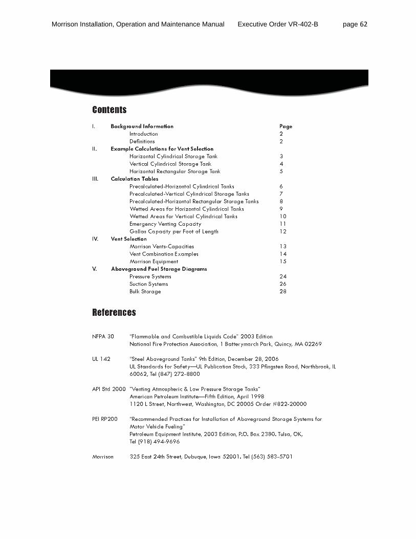
Morrison Installation, Operation and Maintenance Manual Executive Order VR-402-B page 62
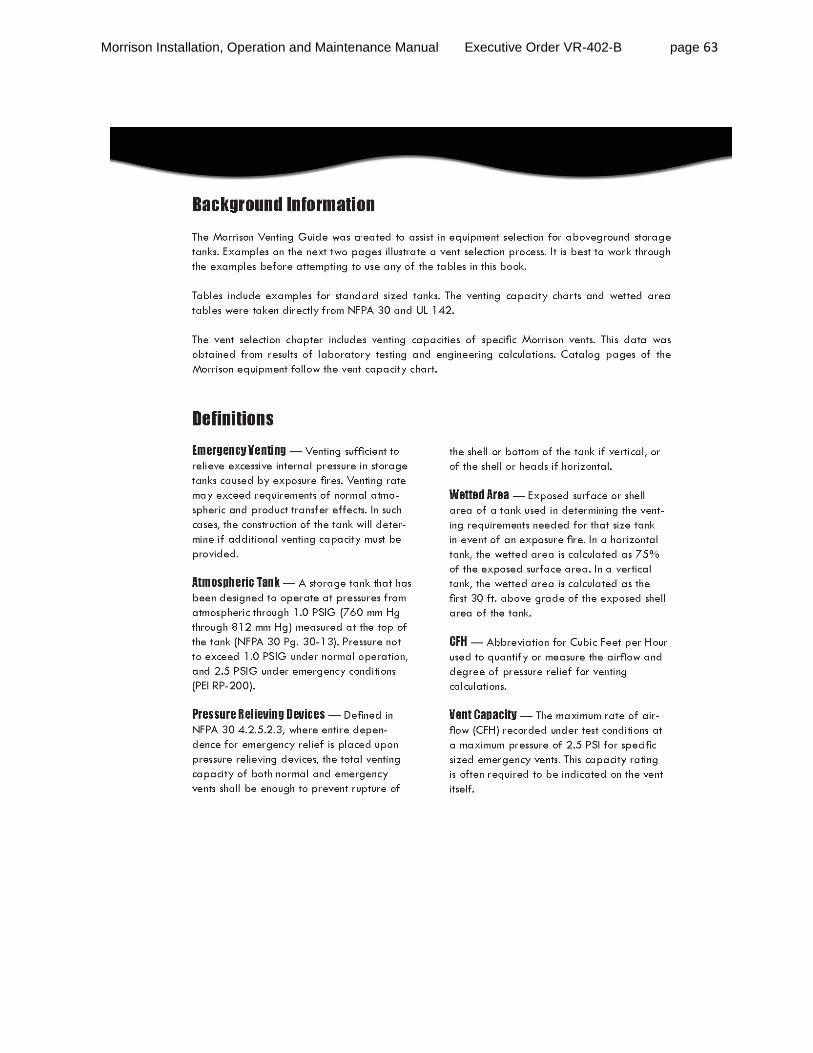
Morrison Installation, Operation and Maintenance Manual Executive Order VR-402-B page 63
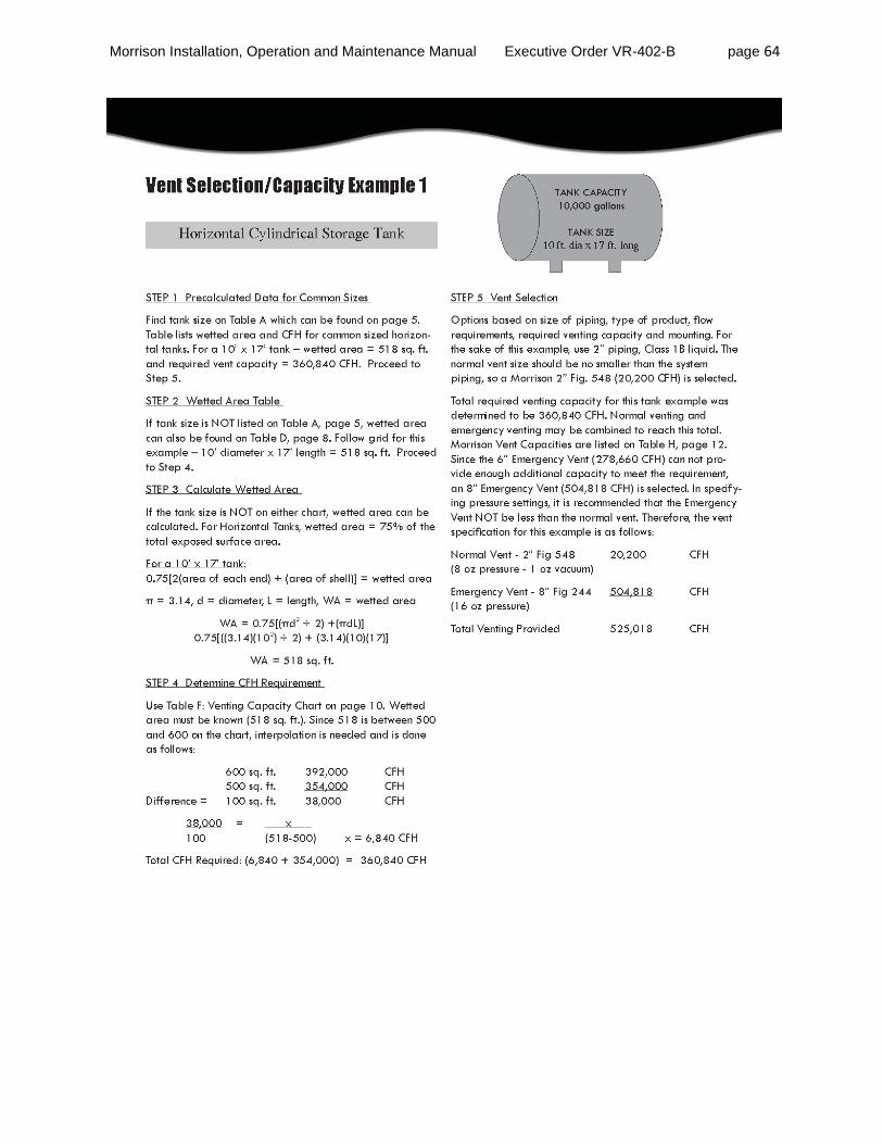
Morrison Installation, Operation and Maintenance Manual Executive Order VR-402-B page 64

Morrison Installation, Operation and Maintenance Manual Executive Order VR-402-B page 65

Morrison Installation, Operation and Maintenance Manual Executive Order VR-402-B page 66

Morrison Installation, Operation and Maintenance Manual Executive Order VR-402-B page 67

Morrison Installation, Operation and Maintenance Manual Executive Order VR-402-B page 68

Morrison Installation, Operation and Maintenance Manual Executive Order VR-402-B page 69

Morrison Installation, Operation and Maintenance Manual Executive Order VR-402-B page 70
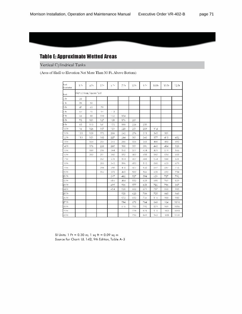
Morrison Installation, Operation and Maintenance Manual Executive Order VR-402-B page 71

Morrison Installation, Operation and Maintenance Manual Executive Order VR-402-B page 72
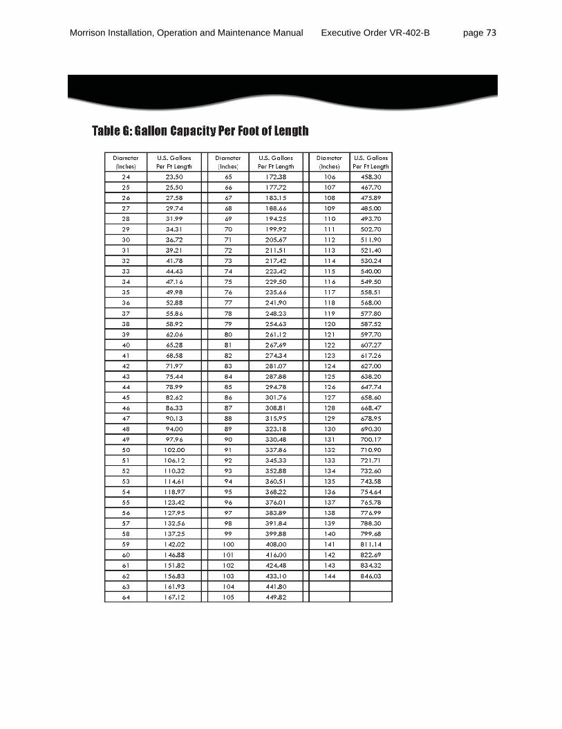
Morrison Installation, Operation and Maintenance Manual Executive Order VR-402-B page 73
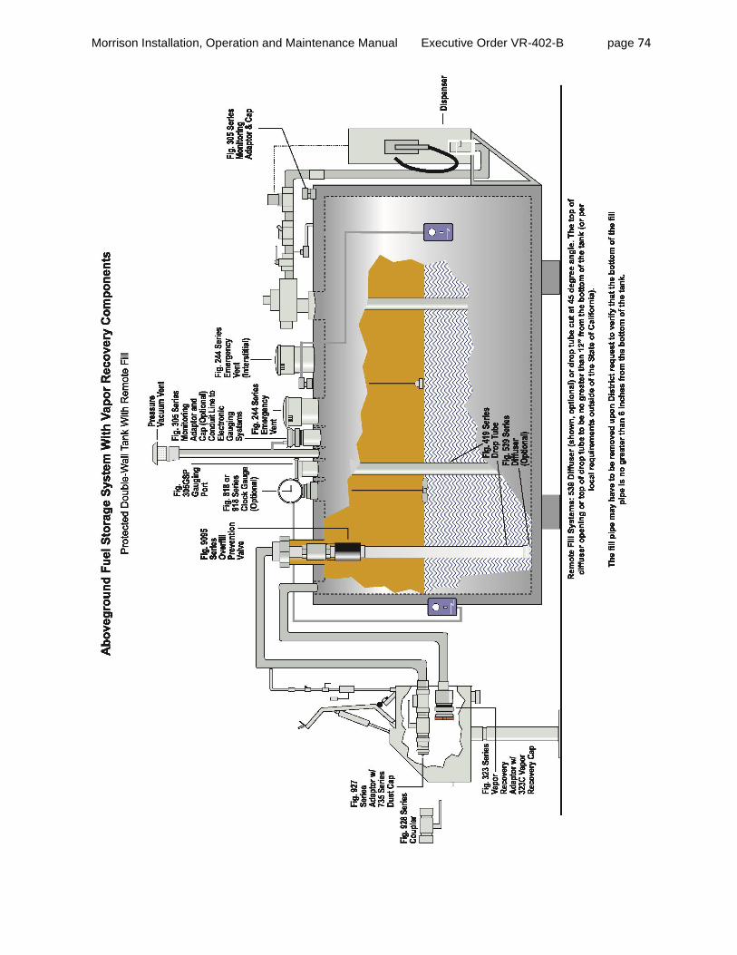
Morrison Installation, Operation and Maintenance Manual Executive Order VR-402-B page 74

Morrison Installation, Operation and Maintenance Manual Executive Order VR-402-B page 75

Morrison Installation, Operation and Maintenance Manual Executive Order VR-402-B page 76
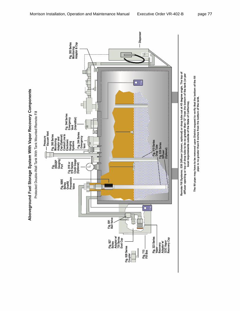
Morrison Installation, Operation and Maintenance Manual Executive Order VR-402-B page 77

Morrison Installation, Operation and Maintenance Manual Executive Order VR-402-B page 78
EVR Aboveground Storage Tank Components Installation Specifications
(May 23, 2012)
A. Wrench Makeup Method
Wrench Makeup*
Size (Number of Turns)
2” NPT Threads 3.25
3” NPT Threads 2
4” NPT Threads 2.12
5” NPT Threads 2.25
6” NPT Threads 2.50
8” NPT Threads 2.75
* - All sizes should have handtight engagement before Wrench Makeup is applied. All threads should be prepared with a fuel resistant, non-hardening, anti-seize sealant. Morrison recommends thread sealant rather than Teflon® tape. A tolerance of plus or minus one turn is allowed. This information is to be used as guide only. The number of turns may vary depending on the quality of thread form. This method is allowed for states outside of California.
B. Torque Method
Component Size Torque Specification*
Vapor Adaptor 3" 75-100 ft-lb
4" 23-26 ft-lb
Product Adaptor 2" 75-85 ft-lb
3" 75-100 ft-lb
4" 23-26 ft-lb
Monitoring Adaptor 2", 4" 23-26 ft-lb
Dedicated Gauging Port Adaptor 2" 23-26 ft-lb
Spill Container 4" 75-100 ft-lb
Tank Gauge 2" 75-85 ft-lb
Emergency Vent 2" 75-85 ft-lb
3"-4" 75-100 ft-lb
* - No special tools required. Torque value could be verified by offset chain wrench and torque wrench. The Torque method is required rather than Wrench Makeup method for components installed in California,.

Morrison Installation, Operation and Maintenance Manual Executive Order VR-402-B page 79 Summary of Guidelines for Maintenance Activities Required of Morrison EVR Aboveground Storage Tank Equipment
Component Interval Maintenance To Be Performed
Emergency Vents Morrison 244 Series Annual Annual inspection, and immediate inspection during
freezing conditions, by someone familiar with the proper
operation of the storage tank vents, is required to insure
venting devices are functioning properly before filling or
unloading a tank. Lift the cover of the vent all the way up and lower back down onto the body several times. The cover must move freely for the vent to work properly. Replace the unit if sticking or binding occurs. Inspect the vent, including the seal area, for dust, debris, snow or ice. Remove any that is found. Inspect all vent components and surfaces for damage, corrosion or excessive wear. If any is found replace the vent. If painting, extreme caution must be exercised to
make sure that the paint does not inhibit proper vent
operation.
Spill Container Morrison 516 Series Annual Clean and remove any dirt, debris or spilled product from the
& 515 Series
spill container as it accumulates. Observe the container to
assure proper performance. Visually inspect exterior and
interior of container on a regular basis, or at least once a
year to ensure the product is not worn or damaged to
affect the functionality of the parts.
Drop Tube Overfill Prevention Device Morrison 9095A Series None No maintenance is required for this product, but local codes
may require specific procedures.
Drop Tube
Morrison 419 Series None No maintenance is required for this product, but local codes
may require specific procedures. It should be verified during installation that the bottom of the drop tube is at the proper distance from the bottom of the tank.
Maintenance guidelines do not replace the use of the Morrison maintenance instructions. Maintenance personnel or owner/operators must refer to the complete installation, maintenance and operation instructions to ensure that all requirements are completed.
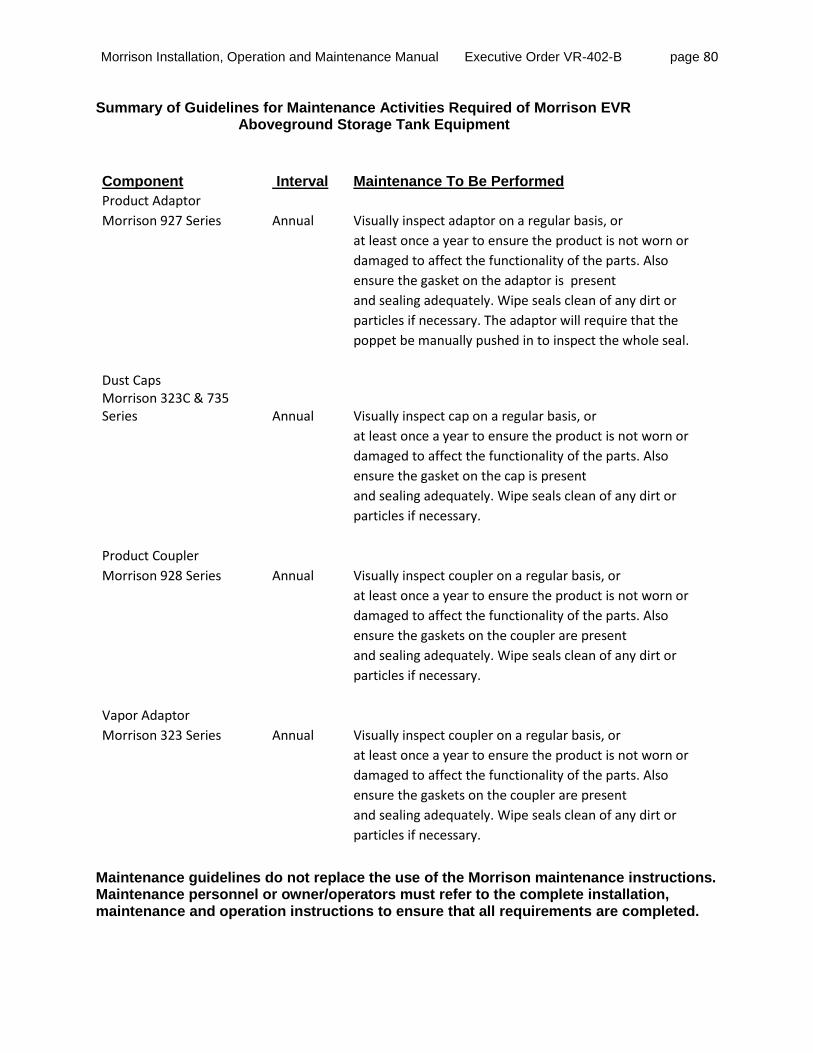
Morrison Installation, Operation and Maintenance Manual Executive Order VR-402-B page 80 Summary of Guidelines for Maintenance Activities Required of Morrison EVR Aboveground Storage Tank Equipment
Component Interval Maintenance To Be Performed
Product Adaptor
Morrison 927 Series Annual Visually inspect adaptor on a regular basis, or
at least once a year to ensure the product is not worn or
damaged to affect the functionality of the parts. Also
ensure the gasket on the adaptor is present
and sealing adequately. Wipe seals clean of any dirt or
particles if necessary. The adaptor will require that the
poppet be manually pushed in to inspect the whole seal.
Dust Caps Morrison 323C & 735
Series Annual Visually inspect cap on a regular basis, or
at least once a year to ensure the product is not worn or
damaged to affect the functionality of the parts. Also
ensure the gasket on the cap is present
and sealing adequately. Wipe seals clean of any dirt or
particles if necessary.
Product Coupler Morrison 928 Series Annual Visually inspect coupler on a regular basis, or
at least once a year to ensure the product is not worn or
damaged to affect the functionality of the parts. Also
ensure the gaskets on the coupler are present
and sealing adequately. Wipe seals clean of any dirt or
particles if necessary.
Vapor Adaptor
Morrison 323 Series Annual Visually inspect coupler on a regular basis, or
at least once a year to ensure the product is not worn or
damaged to affect the functionality of the parts. Also
ensure the gaskets on the coupler are present
and sealing adequately. Wipe seals clean of any dirt or
particles if necessary.
Maintenance guidelines do not replace the use of the Morrison maintenance instructions. Maintenance personnel or owner/operators must refer to the complete installation, maintenance and operation instructions to ensure that all requirements are completed.

Morrison Installation, Operation and Maintenance Manual Executive Order VR-402-B page 81 Summary of Guidelines for Maintenance Activities Required of Morrison EVR Aboveground Storage Tank Equipment
Component Interval Maintenance To Be Performed
Gauging Port Morrison 305 Series Annual Visually inspect cap and adaptor on a regular basis, or
at least once a year to ensure the product is not worn or
damaged to affect the functionality of the parts. Also
ensure the gaskets on the cap and adaptor are present
and sealing adequately. Wipe seals clean of any dirt or
particles if necessary.
Tank Gauge
Morrison 818 Series Annual Visually inspect gauge to ensure product is not worn or
& 918 Series
damaged by any objects that could affect the functionality
of the parts. Clean clear face if necessary with a damp
cloth. To minimize static build up, do not use a solvent.
Manually stick tank to verify gauge read out. Repair or
replace parts as needed.
Monitoring Cap
Morrison 305 Series Annual Visually inspect cap on a regular basis, or
at least once a year to ensure the product is not worn or
damaged to affect the functionality of the parts. Also
ensure the gasket on the cap is present
and sealing adequately. Wipe seals clean of any dirt or
particles if necessary.
Maintenance guidelines do not replace the use of the Morrison maintenance instructions. Maintenance personnel or owner/operators must refer to the complete installation, maintenance and operation instructions to ensure that all requirements are completed.

Morrison Installation, Operation and Maintenance Manual Executive Order VR-402-B page 82
Summary of Guidelines for Maintenance Activities Required of Morrison EVR Aboveground Storage Tank Equipment
Component Interval Maintenance To Be Performed
Drop Tube Diffuser Morrison 539 Series None No maintenance is required for this product.
Pressure/Vacuum Vent Valve Husky 5885 Annual Annually inspect the P/V vent valve for foreign objects.
1. Remove screws that hold top cover on. Do not remove
the screens.
2. Remove any debris that might be sitting inside
the lower cover.
3. Check the drain holes in the lower cover to ensure
they are not plugged.
4. Reinstall the top cover.
5. Tighten the screws firmly.
Maintenance guidelines do not replace the use of the Morrison maintenance instructions. Maintenance personnel or owner/operators must refer to the complete installation, maintenance and operation instructions to ensure that all requirements are completed.

Morrison Installation, Operation and Maintenance Manual Executive Order VR-402-B page 83
Morrison Above Ground Storage Tank EVR Equipment
Installation Check List
Site Identification Information
Installation Date: __________________ Installation Company: Name __________________________________________________ Address _________________________________________________ City ______________________ State _______ Zip _____________ Business At Installation Site: Name ___________________________________________________ Address __________________________________________________ City ______________________ State _______ Zip _____________ Technician’s Name (Print): _____________________________________________________ Technician’s Signature: _____________________________________________________

Morrison Installation, Operation and Maintenance Manual Executive Order VR-402-B page 84
Morrison Above Ground Storage Tank EVR Equipment
Installation Check List
Components Installed Emergency Vents
__ Morrison 244 Series Spill Container __ Morrison 516 Series __ Morrison 515 Series Drop Tube Overfill Prevention Device __ Morrison 9095A Series Drop Tube __ Morrison 419 Series Product Adaptor __ Morrison 927 Series Dust Caps __ Morrison 323C __ Morrison 735 Series
Product Coupler __ Morrison 928 Series Vapor Adaptor __ Morrison 323 Series Gauging Port __ Morrison 305 Series __ Morrison 735 Series Tank Gauge __ Morrison 818 Series __ Morrison 918 Series Monitoring Cap & Adaptor __ Morrison 305 Series Drop Tube Diffuser __ Morrison 539 Series

Morrison Installation, Operation and Maintenance Manual Executive Order VR-402-B page 85
Morrison
Above Ground Storage Tank EVR Equipment Installation Check List
Installation Acknowledgment Thread sealant compound used at installation _____________________________________ Emergency Vents
__ Morrison 244 Series Wrench Makeup Number of Turns ______ Spill Container __ Morrison 516 Series Wrench Makeup Number of Turns ______ __ Morrison 515 Series Wrench Makeup Number of Turns ______ Drop Tube Overfill Prevention Device __ Morrison 9095A Series Wrench Makeup Number of Turns ______ Product Adaptor __ Morrison 927 Series Wrench Makeup Number of Turns ______ Product Coupler __ Morrison 928 Series Wrench Makeup Number of Turns ______ Vapor Adaptor __ Morrison 323 Series Wrench Makeup Number of Turns ______ Gauging Port Adaptor __ Morrison 305 Series Wrench Makeup Number of Turns ______ Tank Gauge __ Morrison 818 Series Wrench Makeup Number of Turns ______ __ Morrison 918 Series Wrench Makeup Number of Turns ______ Monitoring Adaptor __ Morrison 305 Series Wrench Makeup Number of Turns ______ Drop Tube Diffuser (Thread on style) __ Morrison 539 Series Wrench Makeup Number of Turns ______


![Index [assets.cambridge.org] · associated leuconorite, 402 associated quartz mangerite, 402 coarse grain size, 401, 402 composition of plagioclase, 402 crystal size distribution](https://img.pdfslide.us/doc/110x75/606c9147757c7d7d903e2249/index-associated-leuconorite-402-associated-quartz-mangerite-402-coarse-grain.jpg)