Embed Size (px)
Citation preview
Biomedical Instrumentation B18/BME2
Biomedical
Instrumentation Revision Session
B18/BME2
Dr Gari Clifford
Biomedical Instrumentation B18/BME2
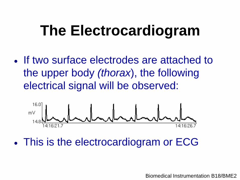
The Electrocardiogram
If two surface electrodes are attached to
the upper body (thorax), the following
electrical signal will be observed:
This is the electrocardiogram or ECG
Biomedical Instrumentation B18/BME2
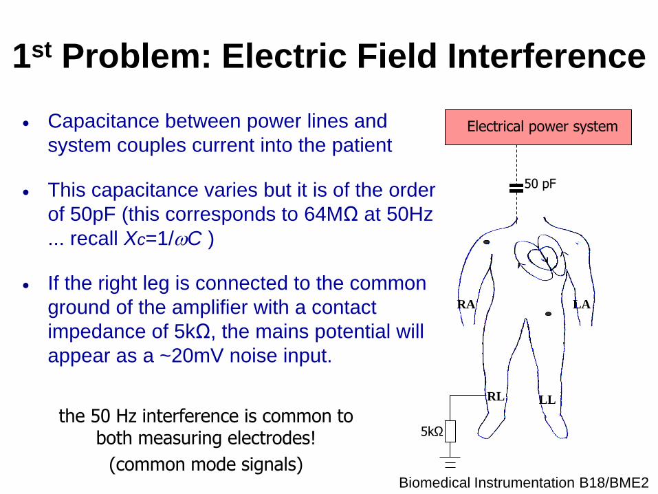
1st Problem: Electric Field Interference
Capacitance between power lines and
system couples current into the patient
This capacitance varies but it is of the order
of 50pF (this corresponds to 64MΩ at 50Hz
... recall Xc=1/C )
If the right leg is connected to the common
ground of the amplifier with a contact
impedance of 5kΩ, the mains potential will
appear as a ~20mV noise input.
RA
LL RL
LA
Electrical power system
50 pF
5kΩ the 50 Hz interference is common to
both measuring electrodes!
(common mode signals)
Biomedical Instrumentation B18/BME2
The solution The ECG is measured as a differential signal.
The 50Hz noise, however, is common to all the
electrodes.
It appears equally at the Right Arm and Left Arm
terminals.
Rejection therefore depends on the use of a
differential amplifier in the input stage of the
ECG machine.
The amount of rejection depends on the ability
of the amplifier to reject common-mode voltages.
Biomedical Instrumentation B18/BME2
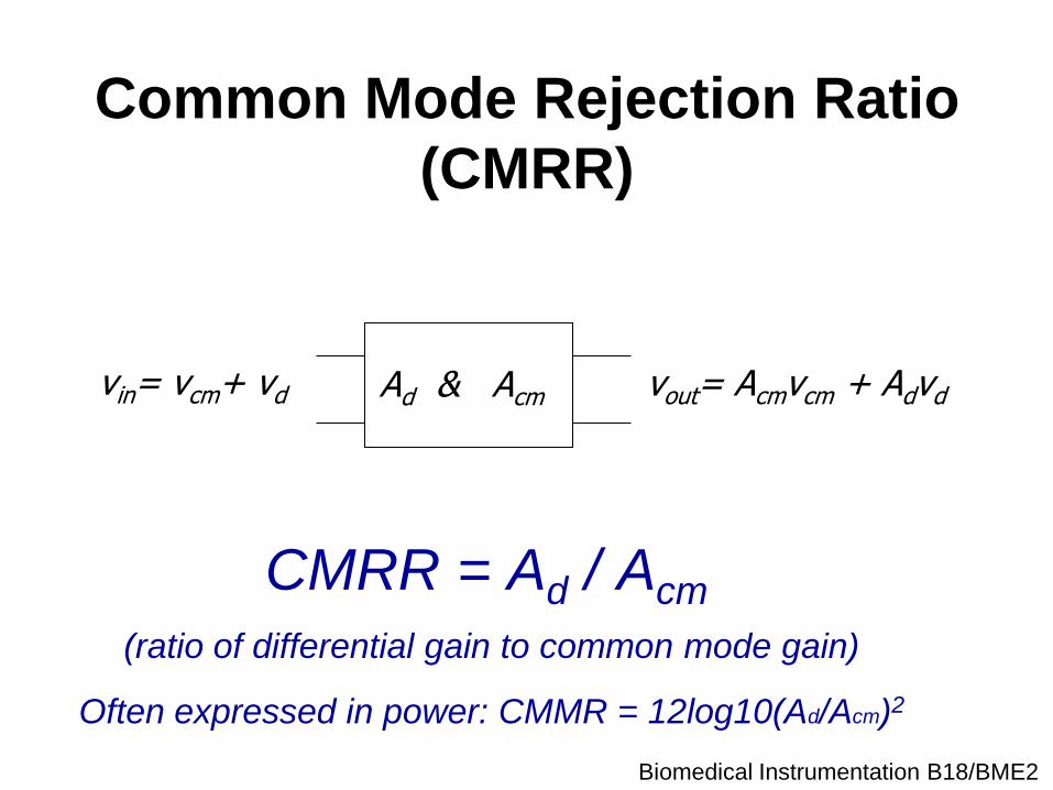
Common Mode Rejection Ratio
(CMRR)
CMRR = Ad / Acm
vin= vcm+ vd vout= Acmvcm + Advd Ad & Acm
(ratio of differential gain to common mode gain)
Often expressed in power: CMMR = 12log10(Ad/Acm)2
Biomedical Instrumentation B18/BME2
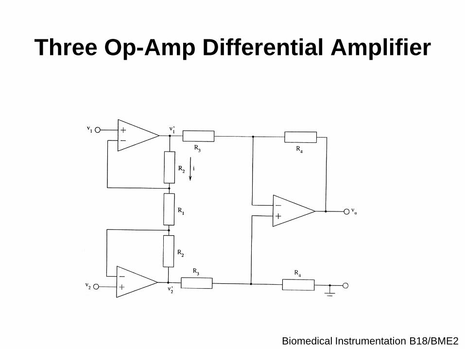
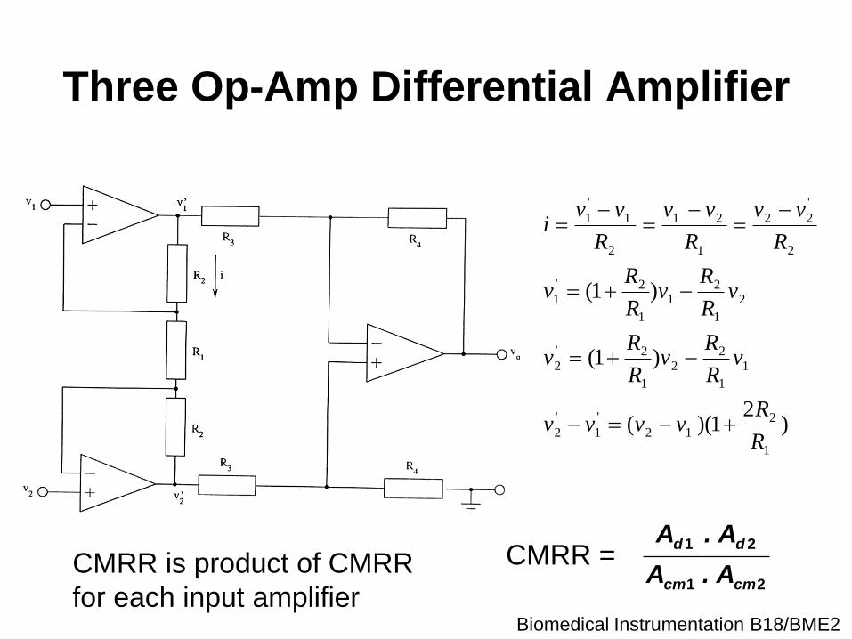
Three Op-Amp Differential Amplifier
Biomedical Instrumentation B18/BME2
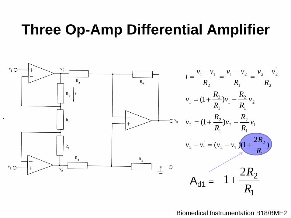
Three Op-Amp Differential Amplifier
Ad1 =
)2
1)((
)1(
)1(
1
212
'
1
'
2
1
1
22
1
2'
2
2
1
21
1
2'
1
2
'
22
1
21
2
1
'
1
R
Rvvvv
vR
Rv
R
Rv
vR
Rv
R
Rv
R
vv
R
vv
R
vvi
1
221
R
R
.
Ad1 =
Biomedical Instrumentation B18/BME2
Ad1 =
)2
1)((
)1(
)1(
1
212
'
1
'
2
1
1
22
1
2'
2
2
1
21
1
2'
1
2
'
22
1
21
2
1
'
1
R
Rvvvv
vR
Rv
R
Rv
vR
Rv
R
Rv
R
vv
R
vv
R
vvi
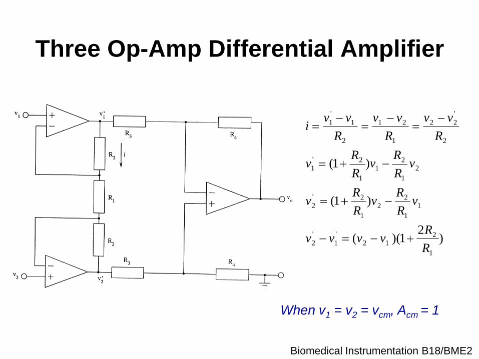
When v1 = v2 = vcm, Acm = 1
Three Op-Amp Differential Amplifier
Biomedical Instrumentation B18/BME2
Ad1 =
)2
1)((
)1(
)1(
1
212
'
1
'
2
1
1
22
1
2'
2
2
1
21
1
2'
1
2
'
22
1
21
2
1
'
1
R
Rvvvv
vR
Rv
R
Rv
vR
Rv
R
Rv
R
vv
R
vv
R
vvi
21
21
cmcm
dd
A.A
A.ACMRR =
Three Op-Amp Differential Amplifier
CMRR is product of CMRR
for each input amplifier
Biomedical Instrumentation B18/BME2
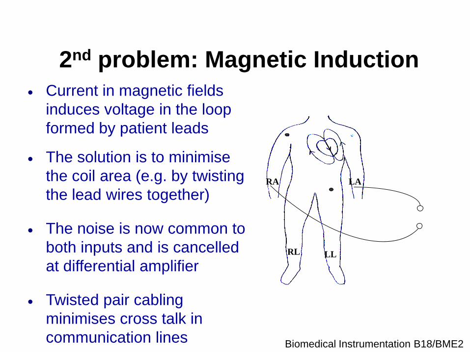
2nd problem: Magnetic Induction
Current in magnetic fields
induces voltage in the loop
formed by patient leads
RA
LL RL
LA
The solution is to minimise
the coil area (e.g. by twisting
the lead wires together)
The noise is now common to
both inputs and is cancelled
at differential amplifier
Twisted pair cabling
minimises cross talk in
communication lines
Biomedical Instrumentation B18/BME2
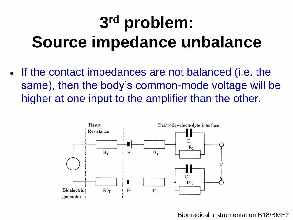
3rd problem:
Source impedance unbalance
If the contact impedances are not balanced (i.e. the
same), then the body’s common-mode voltage will be
higher at one input to the amplifier than the other.
Biomedical Instrumentation B18/BME2
3rd problem:
Source impedance unbalance
If the contact impedances are not balanced (i.e. the
same), then the body’s common-mode voltage will be
higher at one input to the amplifier than the other.
Hence, a fraction of the common-mode voltage will be
seen as a differential signal.
Biomedical Instrumentation B18/BME2
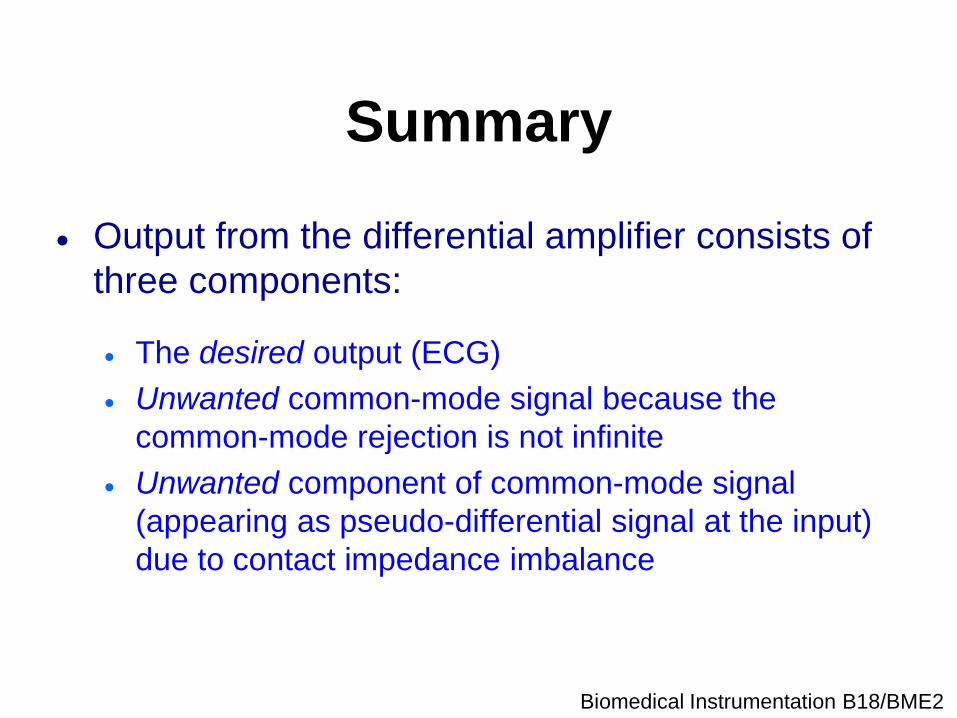
Summary
Output from the differential amplifier consists of
three components:
The desired output (ECG)
Unwanted common-mode signal because the
common-mode rejection is not infinite
Unwanted component of common-mode signal
(appearing as pseudo-differential signal at the input)
due to contact impedance imbalance
Biomedical Instrumentation B18/BME2
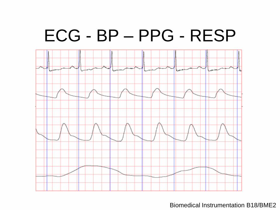
ECG - BP – PPG - RESP
Biomedical Instrumentation B18/BME2
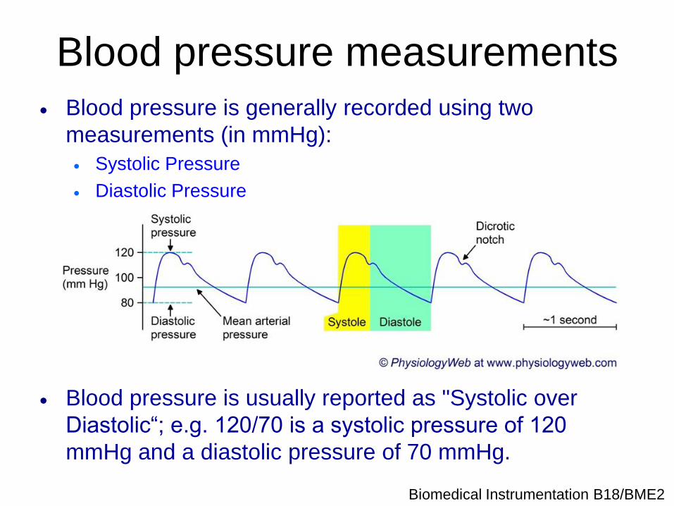
Blood pressure measurements
Blood pressure is generally recorded using two
measurements (in mmHg):
Systolic Pressure
Diastolic Pressure
Blood pressure is usually reported as "Systolic over
Diastolic“; e.g. 120/70 is a systolic pressure of 120
mmHg and a diastolic pressure of 70 mmHg.
Biomedical Instrumentation B18/BME2
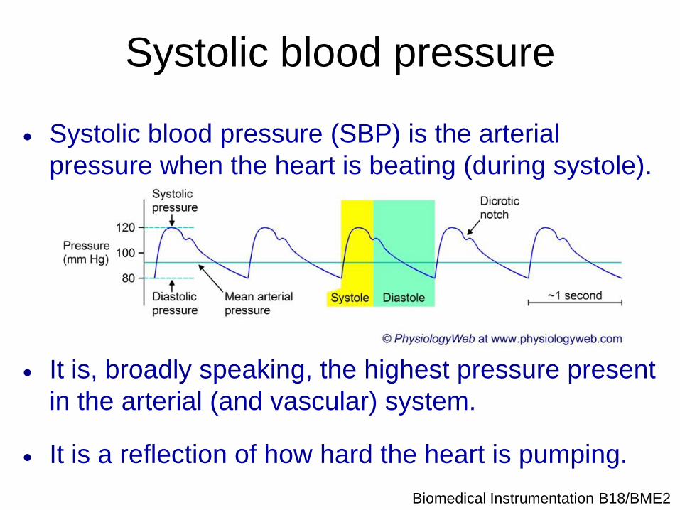
Systolic blood pressure
Systolic blood pressure (SBP) is the arterial
pressure when the heart is beating (during systole).
It is, broadly speaking, the highest pressure present
in the arterial (and vascular) system.
It is a reflection of how hard the heart is pumping.
Biomedical Instrumentation B18/BME2
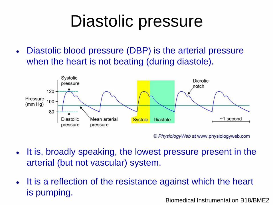
Diastolic pressure
Diastolic blood pressure (DBP) is the arterial pressure
when the heart is not beating (during diastole).
It is, broadly speaking, the lowest pressure present in the
arterial (but not vascular) system.
It is a reflection of the resistance against which the heart
is pumping.
Biomedical Instrumentation B18/BME2
Oscillometry
Marey (1885) noted that the pressure in a vessel
containing an arm fluctuated with the beating of
the heart.
The magnitude of these pressure fluctuations
varied with the applied pressure
Modern version involved an inflatable cuff
around the arm
Biomedical Instrumentation B18/BME2
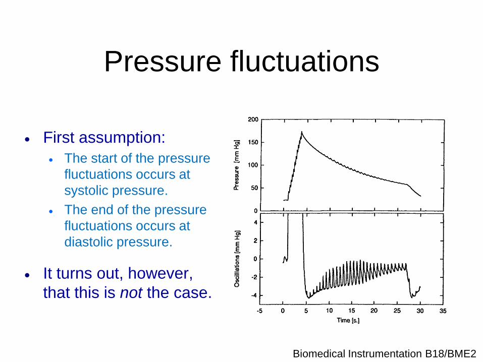
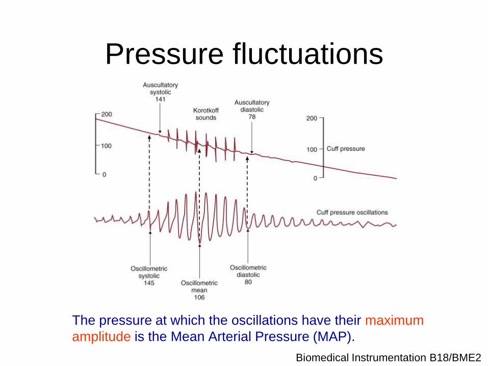
Pressure fluctuations
First assumption:
The start of the pressure
fluctuations occurs at
systolic pressure.
The end of the pressure
fluctuations occurs at
diastolic pressure.
It turns out, however,
that this is not the case.
Biomedical Instrumentation B18/BME2
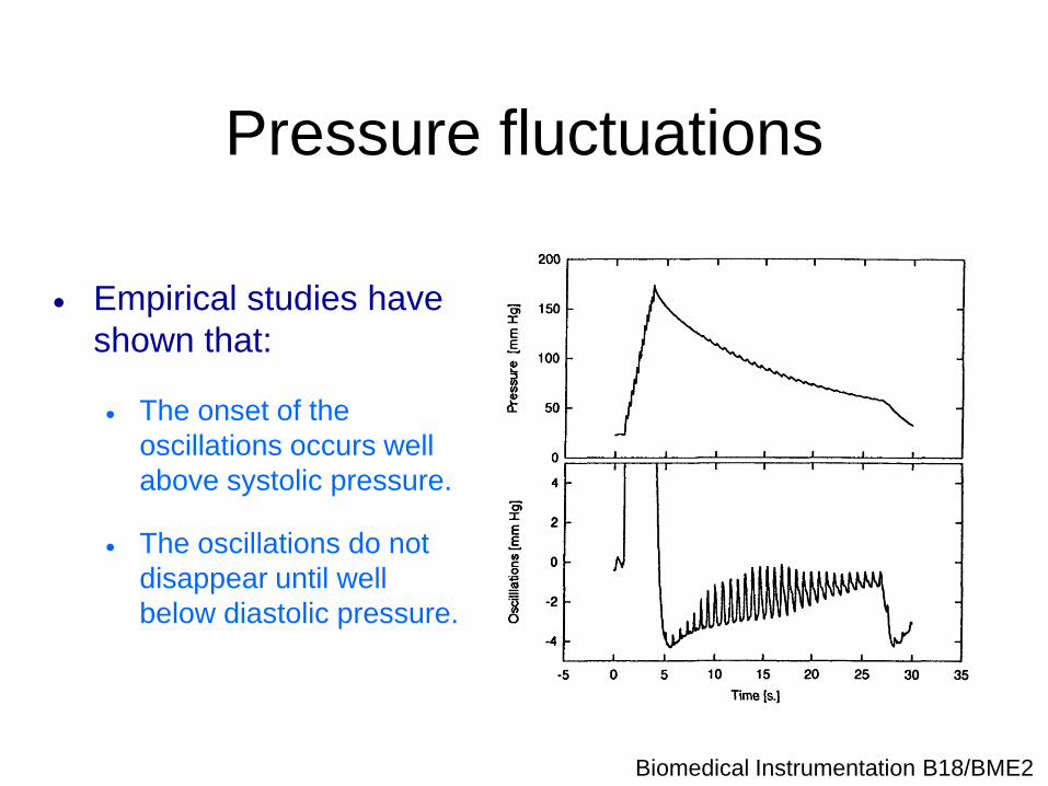
Pressure fluctuations
Empirical studies have
shown that:
The onset of the
oscillations occurs well
above systolic pressure.
The oscillations do not
disappear until well
below diastolic pressure.
Biomedical Instrumentation B18/BME2
Pressure fluctuations
The pressure at which the oscillations have their maximum
amplitude is the Mean Arterial Pressure (MAP).
Biomedical Instrumentation B18/BME2
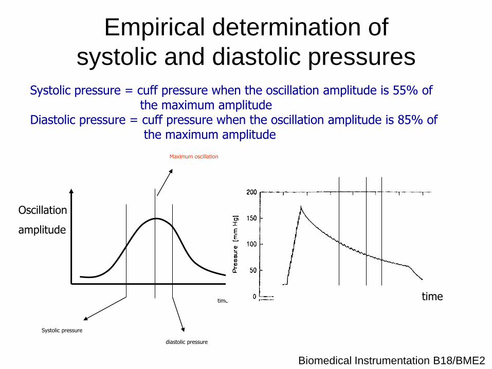
Empirical determination of
systolic and diastolic pressures
time
Oscillation
amplitude
time
Maximum oscillation
Systolic pressure
diastolic pressure
Systolic pressure = cuff pressure when the oscillation amplitude is 55% of the maximum amplitude Diastolic pressure = cuff pressure when the oscillation amplitude is 85% of the maximum amplitude
Biomedical Instrumentation B18/BME2
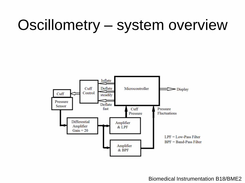
Oscillometry – system overview
Biomedical Instrumentation B18/BME2
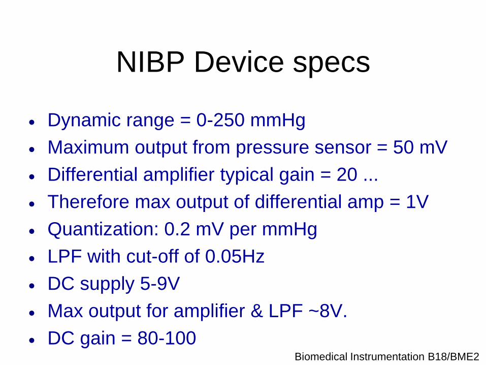
NIBP Device specs
Dynamic range = 0-250 mmHg
Maximum output from pressure sensor = 50 mV
Differential amplifier typical gain = 20 ...
Therefore max output of differential amp = 1V
Quantization: 0.2 mV per mmHg
LPF with cut-off of 0.05Hz
DC supply 5-9V
Max output for amplifier & LPF ~8V.
DC gain = 80-100
Biomedical Instrumentation B18/BME2
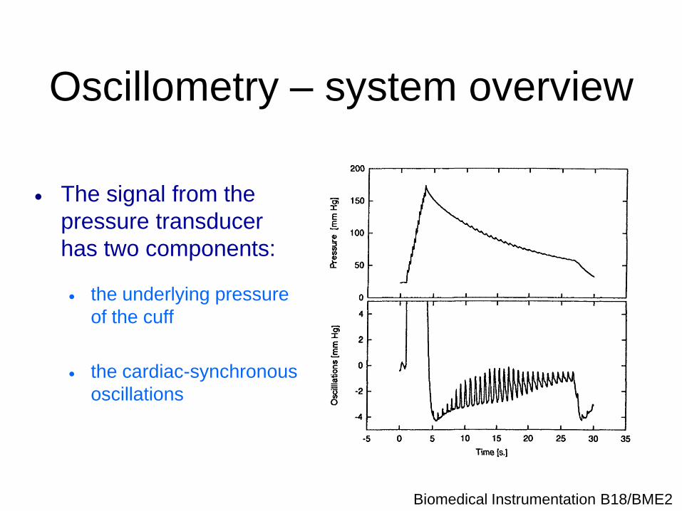
Oscillometry – system overview
The signal from the
pressure transducer
has two components:
the underlying pressure
of the cuff
the cardiac-synchronous
oscillations
Biomedical Instrumentation B18/BME2
Pressure measurement system
The pressure measurement system
consists of the following:
A pressure transducer to sense the cuff
pressure (including the cardiac-synchronous
oscillations)
Amplification and filtering
Analogue-to-digital conversion
Biomedical Instrumentation B18/BME2
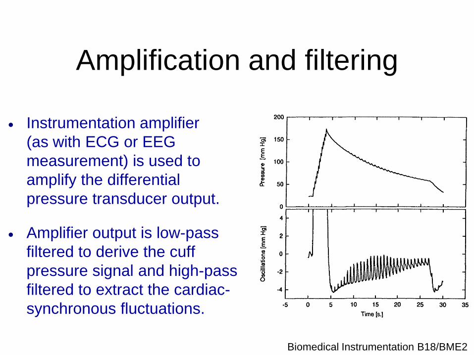
Amplification and filtering
Instrumentation amplifier
(as with ECG or EEG
measurement) is used to
amplify the differential
pressure transducer output.
Amplifier output is low-pass
filtered to derive the cuff
pressure signal and high-pass
filtered to extract the cardiac-
synchronous fluctuations.
Biomedical Instrumentation B18/BME2
Analogue-to-digital conversion
Sampling frequency:
Accurate peak detection requires 10 samples per cycle of
cardiac-synchronous fluctuations → choose a sampling
frequency of 50 Hz or above for that channel.
Amplitude resolution:
8-bit accuracy should be sufficient for A-D conversion:
Low-pass filtered cuff pressure signal needs to be resolved to
1 or 2 mmHg in a range of 0 to 300 mmHg
High-pass filtered cardiac-synchronous fluctuations will be
digitised with 0.5% accuracy.
Biomedical Instrumentation B18/BME2
Signal processing
Software will perform the following functions:
Initiating the measurement cycle and driving the cuff controller (or
telling the user to pump’)
Reading in the digitised data
Recording the amplitude of the cardiac-synchronous fluctuations at
the different cuff pressures
Computing mean, systolic and diastolic pressures
Computing pulse rate, if required
(It is of course possible for the low-pass and high-pass
filtering of the overall cuff pressure signal also to be
performed in software after A-D conversion of the amplifier
output.)
Biomedical Instrumentation B18/BME2
Revision / Exam Tips
Read past papers – practice answering them in
the allotted time
Recap the connection between signals – ECG,
BP, PPG, resp
Revise simple electronics – Ohm’s law &
Kirchoff’s first law!!!
Just trace around the circuit and remember the
current is conserved at any junction

Biomedical Instrumentation B18/BME2
ECG - BP – PPG - RESP
Biomedical Instrumentation B18/BME2