Embed Size (px)
Citation preview
5G 02 arch YJS 1
Air Interface
5G 02 arch YJS 2
Cells
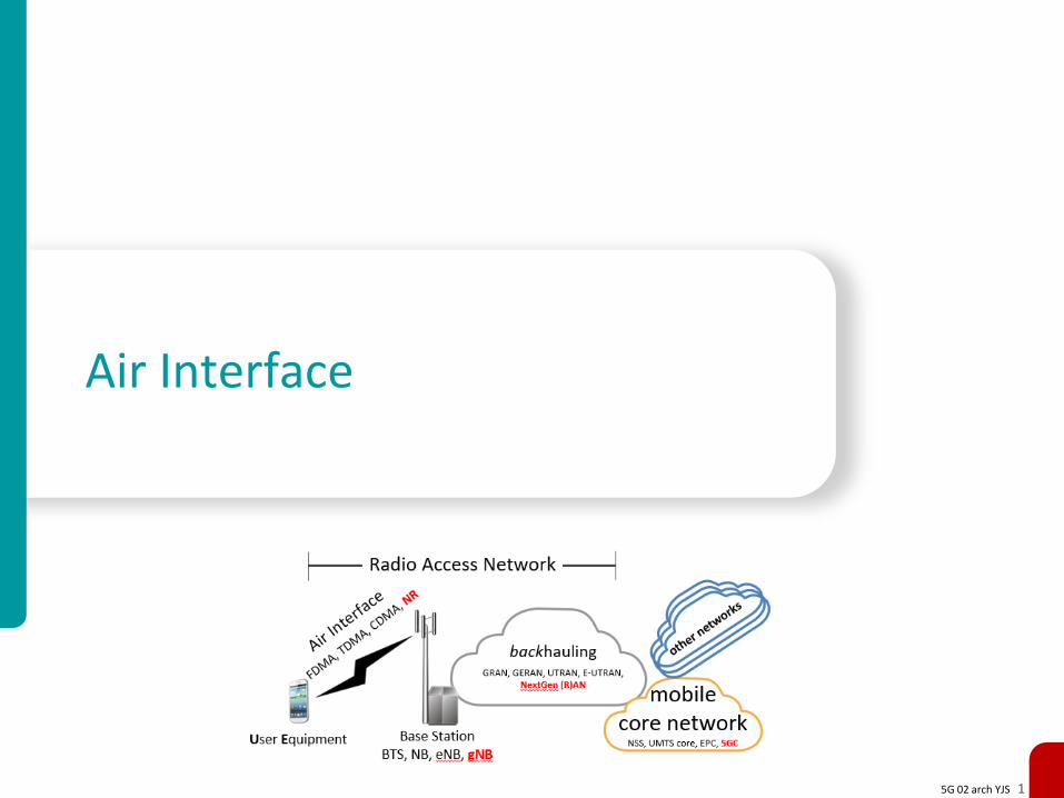
Area to be covered is tessellated with cells, each served by a BSideally circular/hexagonal, but precise pattern determined by planning
• macrocell < 35 km, typically 5-10 km (terrain dependent), about 25w
• small cells– microcell < 2 km about 5w (often used to supplement coverage)– picocell < 200 m < 1w (inside buildings, underground parking, etc.)– femtocell ≈ 10 m 100 mW (home, small businesses)
Each cell may use multiple frequencies to support multiple users in same cellbut adjacent cells do not usually use the same frequencies
Cell boundaries may be dynamice.g., cell breathing is a load balancing mechanism where overloaded cells reduce transmit power (changing service area)thus offloading subscribers neighboring cells
Cells may overlap• in CO-MIMO BSs jointly transmit/receive data to/from users• in CoMP BSs coordinate with each other to reduce interference at edges
5G 02 arch YJS 3
Handoff (handover)
True mobility is implemented by handoff (called handover in Europe) which is when an active call or data session
is transferred from one cell to anothere.g., when user moves out of serving cell’s coverage area
or when serving cell is overloaded
• in hard handoff (break before make) the existing session breaks before new connection is established if performed quickly enough the discontinuity made not be noticed
• in soft (smooth) handoff (make before break) two sessions exist during handoffno discontinuity, but more costly (consumes double resources)
To enable handoff (exact details depend on the protocol)• UE continually monitors signal strength of serving BS and neighboring BSs• UE sends these measurements to network• the network knows channel availability in each cell• the network decides if/when/how to perform handoff
5G 02 arch YJS 4
Antennas
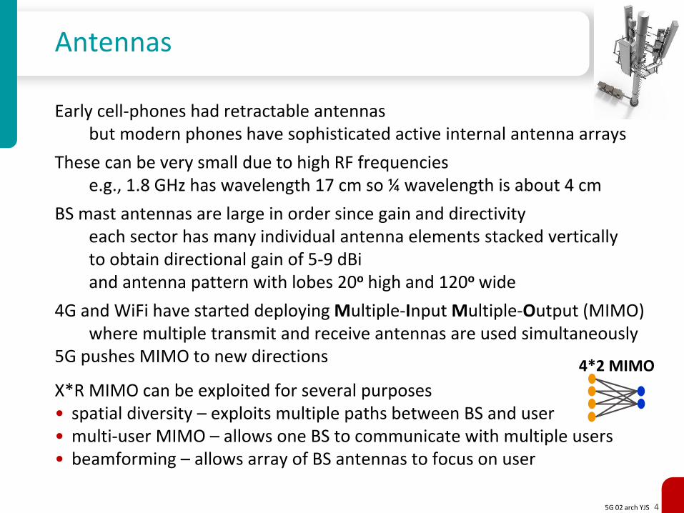
Early cell-phones had retractable antennasbut modern phones have sophisticated active internal antenna arrays
These can be very small due to high RF frequenciese.g., 1.8 GHz has wavelength 17 cm so ¼ wavelength is about 4 cm
BS mast antennas are large in order since gain and directivity each sector has many individual antenna elements stacked vertically to obtain directional gain of 5-9 dBiand antenna pattern with lobes 20o high and 120o wide
4G and WiFi have started deploying Multiple-Input Multiple-Output (MIMO)where multiple transmit and receive antennas are used simultaneously
5G pushes MIMO to new directions
X*R MIMO can be exploited for several purposes• spatial diversity – exploits multiple paths between BS and user• multi-user MIMO – allows one BS to communicate with multiple users• beamforming – allows array of BS antennas to focus on user
4*2 MIMO
5G 02 arch YJS 5
RF spectral bands
Cellular communications takes place in licensed spectral bands most common at 400,450,700,750,800,900,1800,1900,2100,2600 MHzand 5G looking at higher “mm-wave” bands
This differs from unlicensed spectral bands, such as used for WiFisuch as the Industrial, Scientific and Medical bands e.g., 2.4, 5, 24 GHz
The spectral bands available for licensing differ by: • different ITU regions (Americas, Europe, Africa, Asia) • cellular generation (2G, 3G, 4G)• modulation details (EVDO/GSM, FDD/TDD, for TDD up/down-link, etc.)
Spectrum is most often allocated to mobile SPs via auctions• initiated by the FCC in 1994 • 87 US auctions since 1994 assigned 1000s of licenses and raised >$60B• 5G auctions have commenced worldwide
although alternatives (hearings, lotteries) exist
Advantages of auctions• transparent/non-political - allocate spectrum to those who most need it• raise money provided there is enough competition
5G 02 arch YJS 6
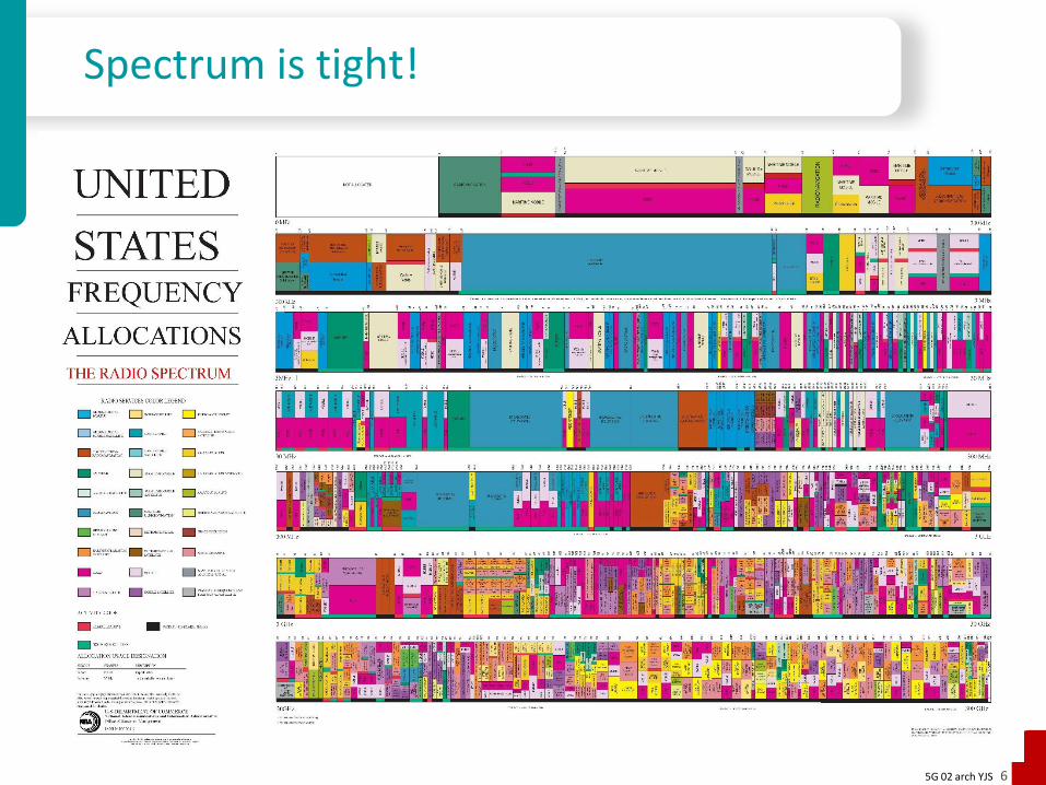
Spectrum is tight!
5G 02 arch YJS 7
Spectral efficiency
Given a spectral bandwidth the obtainable data rate depends on the spectral efficiency specified in bits/sec per Hz (b/s/Hz)
Achievable spectral efficiency for a given BW depends on path loss and noisesince Shannon’s capacity law states C = BW log2(SNR + 1)
Noise sources (see ITU-R P.372-13)• thermal noise (including that of the receiver front end)• atmospheric noise (about 40 lightning flashes per second worldwide)• cosmic background noise• man-made noise
Spectral efficiency has improved from cellular generation to generation• GSM channel spacing is 200 kHz and the digital rate is 16 kBit/sec
so the spectral efficiency is 0.08 b/s/Hz• 3G HSDPA can provide about 14 Mbps in 5 MHz bandwidth
so the spectral efficiency is 2.8 b/s/Hz• LTE R8 DL max channel bandwidth is 20 MHz and max bit rate is 300 Mbps
so the channel efficiency is 15 b/s/Hz • 5G NR may achieve > 50 b/s/Hz !
5G 02 arch YJS 8
Synchronization
BSs of neighboring cells use different frequenciesbut how are these frequency generated?
Any error in frequency will lead to spectral overlap and hence interferencebut leaving guard frequencies would lead to inefficient use of spectrum
Some modulation/duplexing/multiple access techniques additionally need accurate phase (time) in particular to enable smooth handoff
Two synchronization methods are commonly used:• deriving frequency/time from Global Navigation Satellite System (e.g., GPS)• deriving frequency/phase from the backhaul network
– frequency from physical layer - SDH or SyncE– time from time distribution protocols
e.g., IEEE 1588v2 and NTP
5G 02 arch YJS 9
Duplexing
Almost all cellular networks use Frequency Domain Duplexing• (D)AMPS 824-849 MHz uplink (UE→BS), 869-894 MHz downlink (BS→UE) • 2G GSM, e.g., 1710.2-1784.8 uplink, 1805.2-1879.8 DL• 3G UMTS and 4G LTE FDD, e.g., 1920-1980 UL 2110-2170 DL
The alternative is Time Domain Duplexing, used in:• 802.16 WiMAX• 3G TD-SCDMA (Chinese version)• 4G LTE TDD (2.3 GHz and 2.5 GHz bands)
TDD allocates UL and DL time slots in the same frequency band
TDD has advantages• easy to adapt to asymmetric data rates• efficient for bursty data• can attain higher spectral efficiency than FDD (less guard waste)• channel reciprocity• facilitates beamforming
but suffers from the need for highly accurate time synchronization
5G 02 arch YJS 10
Multiple Access
The challenge of Multiple Access in a single cellis that the sources to be muxed are (at least initially) uncoordinated
Different multiple access methods have been used in cellular standards• Frequency Domain MA (AMPS) • Orthogonal FDMA (LTE BS→UE DL, UL uses similar SC-FDMA to improve PAR)• Time Domain MA (D-AMPS)• combined FDMA and TDMA (GSM)• Code Domain MA (2G IS-95, 3G EV-DO)
In FDMA users are allocated frequencies in the frequency band
OFDMA optimizes spectral efficiency by allowing minimal channel spacing
In TDMA users are allocated time slots in a periodic frame
In GSM there are 125 different UL/DL frequency pairseach supporting 8 time slots
In CDMA users are allocated (nearly) orthogonal spreading codes
Resource allocation is performed by the RAN
5G 02 arch YJS 11
Modulation types
Hundreds of modulation techniques have been developedand any have been applied to cellular traffic
1G AMPS used analog Frequency Modulation (30 kHz channel BW)
2G GSM and GPRS (8 kbps) use Gaussian Minimum Shift Keying (PSK variant)
2.75G EDGE data (384kbps) uses 8PSK and evolved to (1.5 Mbps) 16/32-QAM
IS-136 CDMA (8 kbps) uses DQPSK, IS-95 cdmaONE (8 kbps) QPSK/OQPSK
3G UMTS WCDMA (2Mbps) BPSK,QPSK
3G CDMA2000 EV-DO (2 Mbps) uses BPSK,QPSK,16-QAM
3.5G HSPA DL (14Mbps) BPSK,QPSK,16-QAM
3.75G HSPA+ DL (168Mbps) dual carrier, 2*2 MIMO, up to 64-QAM
4G LTE DL (100 Mbps) OFDM + PSK/QAM up to 64-QAM
4.5G LTE-A (300 Mbps) improves LTE using up to 256-QAM (+ MIMO)
5G New Radio is also based on LTE’s OFDMA, but with improvements
5G 02 arch YJS 12
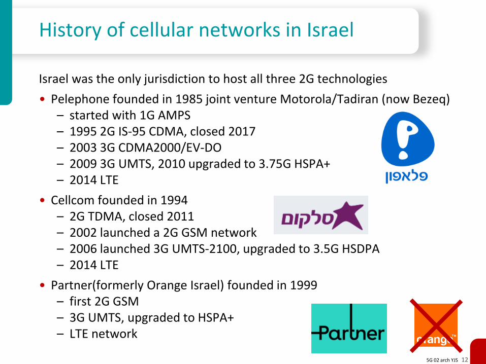
History of cellular networks in Israel
Israel was the only jurisdiction to host all three 2G technologies
• Pelephone founded in 1985 joint venture Motorola/Tadiran (now Bezeq)– started with 1G AMPS– 1995 2G IS-95 CDMA, closed 2017– 2003 3G CDMA2000/EV-DO– 2009 3G UMTS, 2010 upgraded to 3.75G HSPA+– 2014 LTE
• Cellcom founded in 1994– 2G TDMA, closed 2011– 2002 launched a 2G GSM network– 2006 launched 3G UMTS-2100, upgraded to 3.5G HSDPA– 2014 LTE
• Partner(formerly Orange Israel) founded in 1999 – first 2G GSM – 3G UMTS, upgraded to HSPA+– LTE network
5G 02 arch YJS 13
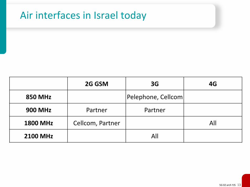
Air interfaces in Israel today
2G GSM 3G 4G
850 MHz Pelephone, Cellcom
900 MHz Partner Partner
1800 MHz Cellcom, Partner All
2100 MHz All
5G 02 arch YJS 14
Radio Access Network
5G 02 arch YJS 15
The need for backhaul
We can imagine connecting cellular base-stations directly to a core networkand modern cellular networks are indeed approaching this ideallogically if not physically
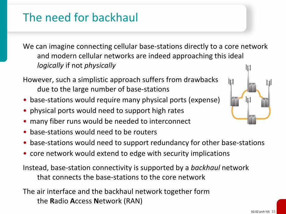
However, such a simplistic approach suffers from drawbacksdue to the large number of base-stations
• base-stations would require many physical ports (expense)
• physical ports would need to support high rates
• many fiber runs would be needed to interconnect
• base-stations would need to be routers
• base-stations would need to support redundancy for other base-stations
• core network would extend to edge with security implications
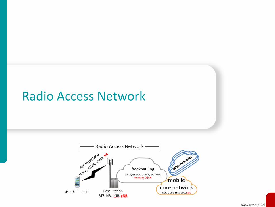
Instead, base-station connectivity is supported by a backhaul networkthat connects the base-stations to the core network
The air interface and the backhaul network together form the Radio Access Network (RAN)
5G 02 arch YJS 16
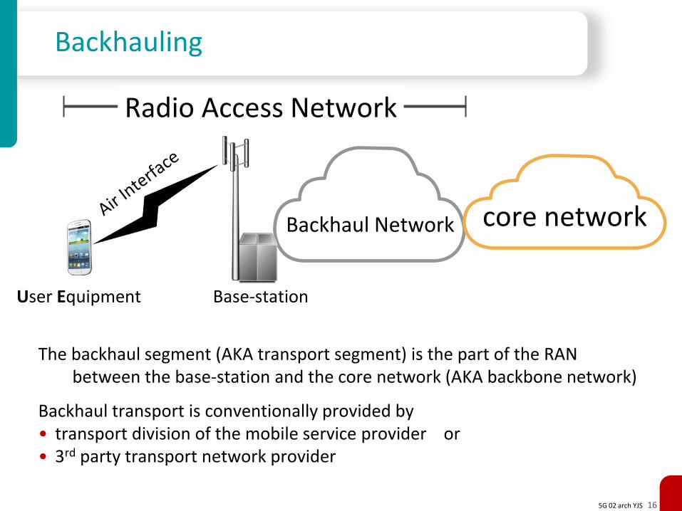
Backhauling
The backhaul segment (AKA transport segment) is the part of the RAN between the base-station and the core network (AKA backbone network)
Backhaul transport is conventionally provided by• transport division of the mobile service provider or• 3rd party transport network provider
User Equipment Base-station
Backhaul Network core network
Radio Access Network
5G 02 arch YJS 17
Backhaul topologies and protocols
Access networks are never richly connected meshes they are conventionally limited to
• star (for small backhaul networks)• daisy chain (e.g., GSM Abis chaining)• tree (implemented actively or using PON)• rings
Backhaul networks rely on various transport technologies• PDH and/or SONET/SDH and/or ATM (2G and 3G)• Point-to-point microwave • Carrier Ethernet networks• IP (IPv4 and IPv6)• MPLS • DSL• satellite
5G 02 arch YJS 18
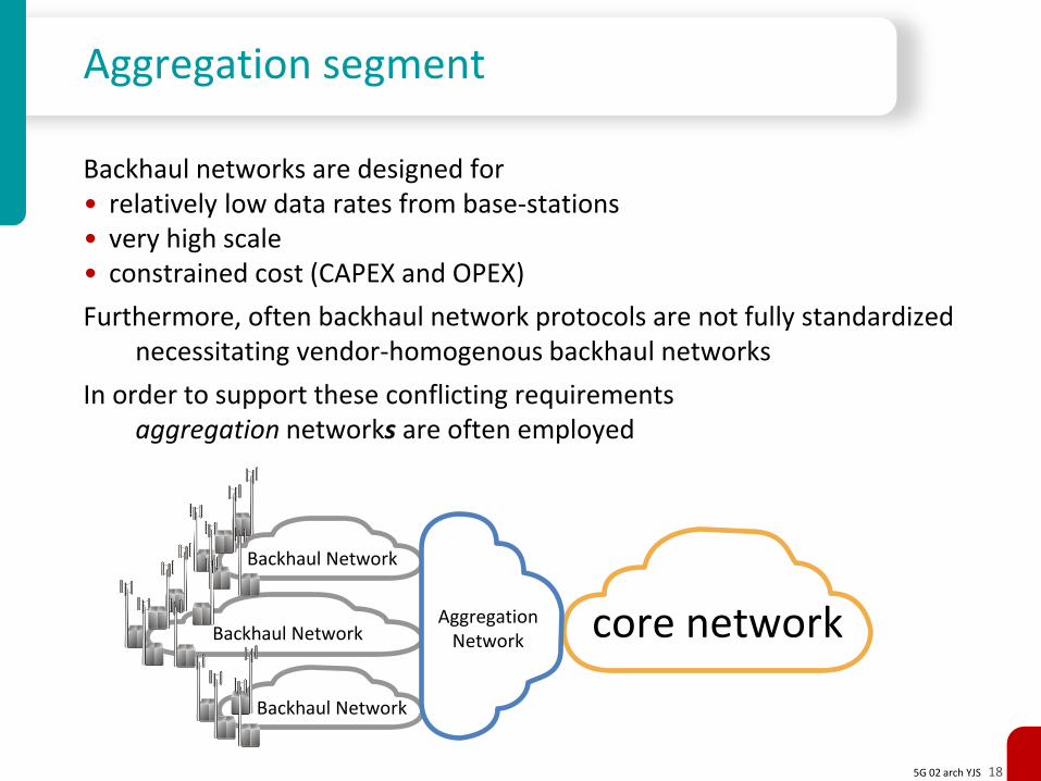
Aggregation segment
Backhaul networks are designed for• relatively low data rates from base-stations• very high scale • constrained cost (CAPEX and OPEX)
Furthermore, often backhaul network protocols are not fully standardizednecessitating vendor-homogenous backhaul networks
In order to support these conflicting requirementsaggregation networks are often employed
Backhaul Network core network
Backhaul Network
Backhaul Network
AggregationNetwork
5G 02 arch YJS 19
Fronthaul
Fronthaul was initially a solution to transport RF from the antenna at the top of a tower and the BS processing at the bottom of the tower
When transporting analog RF in coax there is signal loss and noiseto eliminate, we can perform the A/D conversion close to the antennaand transport a digital bit-stream down the tower
For this purpose 2 protocols were developed:
• Common Public Radio Interface (CPRI)– specified by forum consisting of (Nortel), Ericsson, Huawei, NEC, Nokia– uses complex (I/Q) sampling – carried over dark fiber or OTN
• Open Base Station Architecture Initiative (OBSAI)– specified by forum consisting of Hyundai, LG, Nokia, Samsung, ZTE– uses real (Nyquist) sampling
5G 02 arch YJS 20
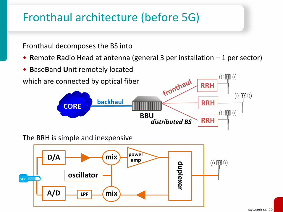
Fronthaul architecture (before 5G)
Fronthaul decomposes the BS into
• Remote Radio Head at antenna (general 3 per installation – 1 per sector)
• BaseBand Unit remotely located
which are connected by optical fiber
The RRH is simple and inexpensive
BBU
backhaulCORE
RRH
RRH
RRH
distributed BS
D/A
A/D
du
plexe
r
power amp
oscillator
mix
mix
SFP
LPF
5G 02 arch YJS 21
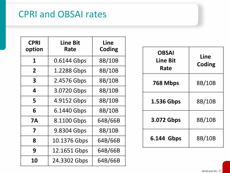
CPRI and OBSAI rates
CPRI option
Line BitRate
LineCoding
1 0.6144 Gbps 8B/10B
2 1.2288 Gbps 8B/10B
3 2.4576 Gbps 8B/10B
4 3.0720 Gbps 8B/10B
5 4.9152 Gbps 8B/10B
6 6.1440 Gbps 8B/10B
7A 8.1100 Gbps 64B/66B
7 9.8304 Gbps 8B/10B
8 10.1376 Gbps 64B/66B
9 12.1651 Gbps 64B/66B
10 24.3302 Gbps 64B/66B
OBSAILine Bit
Rate
LineCoding
768 Mbps 8B/10B
1.536 Gbps 8B/10B
3.072 Gbps 8B/10B
6.144 Gbps 8B/10B
5G 02 arch YJS 22
CRAN, CRAN, and vRAN (before 5G)
Fronthaul decomposes the BS into RRHs and a BBUbut we needn’t locate the BBU at the foot of the tower
It may make sense to have one BBU serve several base-stationsusing fronthaul links, that now need to be much longer
Baseband processing places strict limits on the round-trip delay and thus on the fronthauling distance (e.g., 20 km for LTE)
This architecture is called Centralized RAN (CRAN)and was first promoted by China Mobile in 2010in order to improve scaling of the world’s largest mobile network
Using load-balancing/resilience techniques developed for cloud computingmay allow a central site to service 100s of RRHs
This is called BBU Hotelling or Cloud RAN (CRAN)
If we are already using cloud techniqueswe may implement at least some of the BBU functionality in software(e.g., packet processing, control functionality)
running as virtual machines inside a Data Center
This architecture is called Virtualized RAN

5G 02 arch YJS 23
Mobile Core
5G 02 arch YJS 24
Mobile core networks
Mobile core networks were originally circuit switched (SDH)but have migrated to packet switching using IP technologies
However, unlike the connectionless (CL) Internetthe PSTN and mobile networks are connection oriented (CO)
and mobile cores need to maintain sessions despite mobility
Like all core networks, the mobile core handles transport of user data, with• very high data rates• relatively small number of network elements and links• relatively stable environment
But PSTN and mobile core networks are very different from other IP core networks (e.g., Internet ASes)
• the PSTN assumes dumb terminals and intelligence in the network• the Internet assumes smart terminals and dumb pipes in the network
(the end-to-end principle)
The PSTN and mobile core networks have a rich set of functionalities not present in the Internet model
5G 02 arch YJS 25
Some mobile core functionalities
Some of the functionalities of a mobile core network:
• end-to-end transport of voice traffic (at least until 4G)
• connection oriented data transport (see session management)
• maintenance of sessions despite mobility (see mobility management)
• user (not necessarily true end-user) management – authentication and registration– mobility management (tracking where users are)– user profile, home location, roaming– billing (AKA charging)
• session management (call establishment, management and termination)
• lawful interception (CALEA) and metadata collection
• QoS enforcement (network neutrality is usually not relevant for mobile)
5G 02 arch YJS 26
Elements of the core network (before 5G)
Home Subscriber Server / Home Location Register• database containing user-related and subscriber-related information• support mobility management, call/session setup, user authentication
Serving GateWay (SGSN)• transport traffic between UE and network• mobility anchor point
Packet Data GateWay (GGSN)• interconnection between mobile core and external packet networks
Policy and Charging Rules Function• software component that determines and disseminates policy rules• separated rom PCEF enforcement function
Mobility Management Entity• control plane entity handling signalling related to mobility and security • tracking and paging UEs in idle-mode
5G 02 arch YJS 27
Other Networks
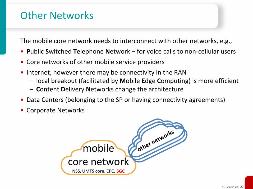
The mobile core network needs to interconnect with other networks, e.g.,
• Public Switched Telephone Network – for voice calls to non-cellular users
• Core networks of other mobile service providers
• Internet, however there may be connectivity in the RAN– local breakout (facilitated by Mobile Edge Computing) is more efficient– Content Delivery Networks change the architecture
• Data Centers (belonging to the SP or having connectivity agreements)
• Corporate Networks
mobilecore network
NSS, UMTS core, EPC, 5GC

5G 02 arch YJS 28
Architecture
5G 02 arch YJS 29
Cellular system architecture
Telecommunications systems architectures are composed of
• Network Elements or Network Functionsin general NEs may be composed of many NFs in which case the NFs may be microservices
• Interfaces or reference points between them
Architectures differ in• types of NEs/NFs• granularity of NEs/NFs • flat networks vs. hierarchical/heterogeneous• separation of user, control, and management planes
Proper (top-down) design starts with architectureand only afterwards designs protocols
5G 02 arch YJS 30
2G GSM interfaces and NEs
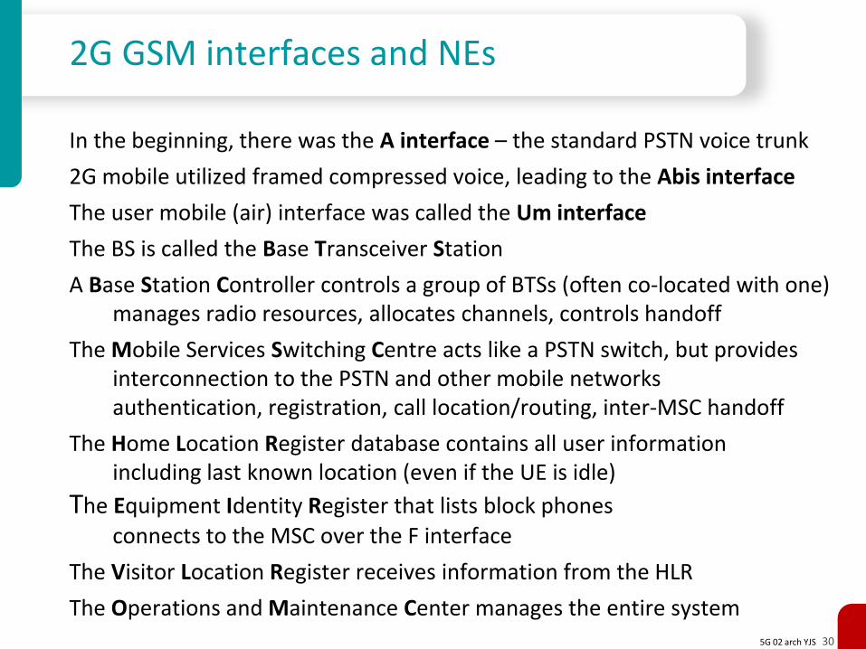
In the beginning, there was the A interface – the standard PSTN voice trunk
2G mobile utilized framed compressed voice, leading to the Abis interface
The user mobile (air) interface was called the Um interface
The BS is called the Base Transceiver Station
A Base Station Controller controls a group of BTSs (often co-located with one)manages radio resources, allocates channels, controls handoff
The Mobile Services Switching Centre acts like a PSTN switch, but provides interconnection to the PSTN and other mobile networksauthentication, registration, call location/routing, inter-MSC handoff
The Home Location Register database contains all user information including last known location (even if the UE is idle)
The Equipment Identity Register that lists block phones
connects to the MSC over the F interface
The Visitor Location Register receives information from the HLR
The Operations and Maintenance Center manages the entire system
5G 02 arch YJS 31
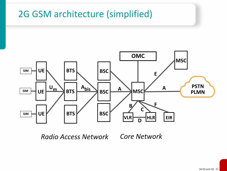
2G GSM architecture (simplified)
UESIM BTS BSC
UESIM
UESIM BTS
BTS
BSC
BSC
MSCPSTNPLMN
Um Abis A
VLR HLR
OMC
A
CB
D
MSC
E
Radio Access Network Core Network
EIR
F
5G 02 arch YJS 32
2.5/3G GPRS NEs
The General Packet Radio Service extends GSM for best effort packet service
In 3G the BTS is replaced by the NodeB
The BSC is replaced by the Radio Network Controller, whichis responsible for controlling the NBsperforms radio resource and some mobility management functions performs encryption of data sent to and from UE
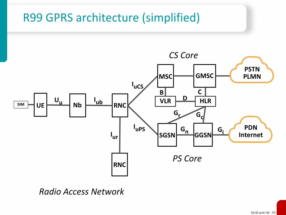
The MSC is the same as in the GSM architecture (replaced in R5 by MGW)but supplemented by a Gateway MSC to connect to the PSTN
Serving GPRS Support Node for packet traffic is similar to MSC+VLR for voiceperforms access control, security functions and tracks UE location
Gateway GPRS Support Node for packet traffic is similar to the GMSC acts as an IP router to connect to external IP networksalso handles billing, filtering and firewall functions
5G 02 arch YJS 33
2.5/3G GPRS interfaces
The Um air interface is replaced with the Uu interface
Iu-CS interface is the interface between the RNC and MSC (MGW in R5)
Iu-PS interface is the interface between the RNC and the SGSN originally over ATM but migrated to IP (SIGTRAN SS7 over IP)
Iur is an optional interface between RNCs for smooth handoff
The Gn interface transports user data and signaling between SGSN and GGSNit uses GPRS Tunnelling Protocol to tunnel through IP networks
The Gp interface is the same as Gn interface but instead to foreign networks
Other G interfaces are for mobility management (HLR, authentication), etc.
5G 02 arch YJS 34
R99 GPRS architecture (simplified)
UESIM Nb RNCUu Iub
Radio Access Network
PS Core
IuCS
IuPSSGSN GGSN
CS Core
RNC
Iur
MSC GMSCPSTNPLMN
PDNInternet
Gn Gi
HLR
C
Gr Gc
VLRB
D
5G 02 arch YJS 35
4G LTE NEs and interfaces
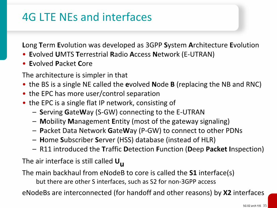
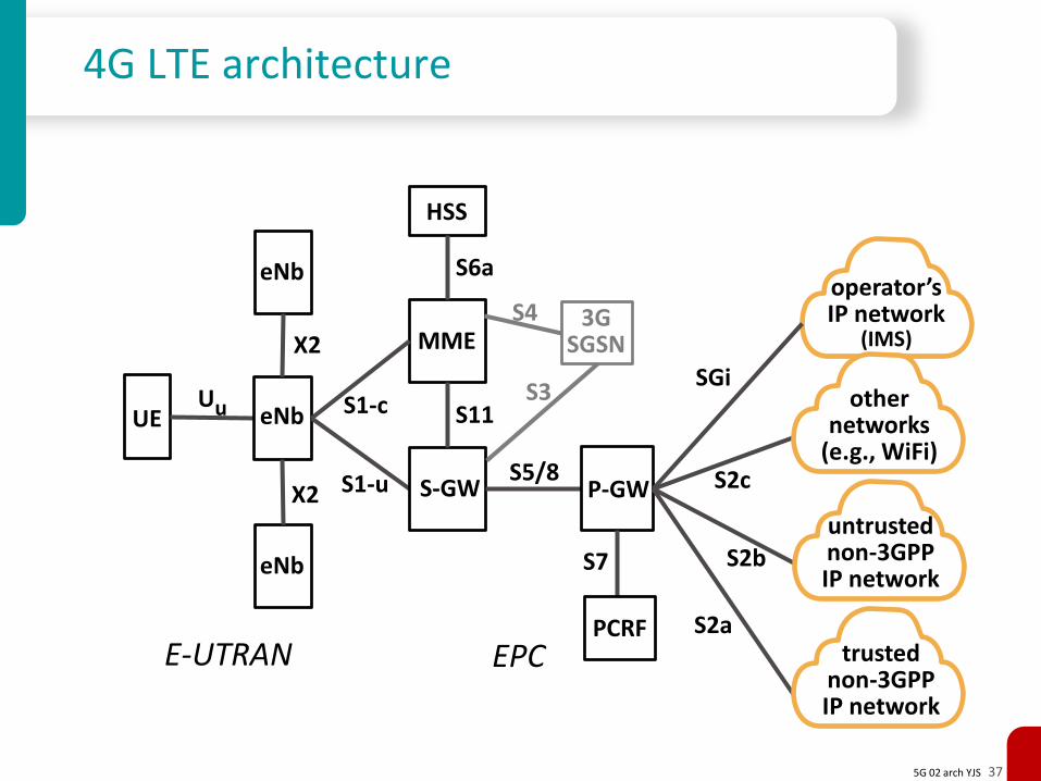
Long Term Evolution was developed as 3GPP System Architecture Evolution • Evolved UMTS Terrestrial Radio Access Network (E-UTRAN)• Evolved Packet Core
The architecture is simpler in that • the BS is a single NE called the evolved Node B (replacing the NB and RNC)• the EPC has more user/control separation• the EPC is a single flat IP network, consisting of
– Serving GateWay (S-GW) connecting to the E-UTRAN– Mobility Management Entity (most of the gateway signaling)– Packet Data Network GateWay (P-GW) to connect to other PDNs– Home Subscriber Server (HSS) database (instead of HLR)– R11 introduced the Traffic Detection Function (Deep Packet Inspection)
The air interface is still called UuThe main backhaul from eNodeB to core is called the S1 interface(s)
but there are other S interfaces, such as S2 for non-3GPP access
eNodeBs are interconnected (for handoff and other reasons) by X2 interfaces
5G 02 arch YJS 36
Functions of some EPC NEs
Mobility Management Entity (MME) • handling of security keys • transitions between idle to active states• sending paging messages to the eNodeBs• bearer setup procedures • contacting the HSS for subscriber information
Serving Gateway (S-GW) • connecting RAN to EPC• mobility anchor when UEs move between eNodeBs• terminates data tunnels between eNodeB and PDN-GW
Packet Data Network Gateway (PDN-GW) • connecting EPC to the internet (and other PDNs)• assigning IP addresses for terminals
Home Subscriber Server (HSS) • subscriber database • allow seamless roaming between networks• connects to MME via S6 interface
5G 02 arch YJS 37
4G LTE architecture
UE eNb
MME
Uu
S1-u
E-UTRAN
operator’sIP network
(IMS)
eNb
eNb
X2
X2 S-GW
S1-c
P-GWS5/8
S11
SGi
trustednon-3GPPIP network
S2a
untrustednon-3GPPIP network
S2b
S2c
othernetworks
(e.g., WiFi)
PCRF
S7
S6a
HSS
3G SGSN
S3
S4
EPC
5G 02 arch YJS 38
4G R14 and CUPS
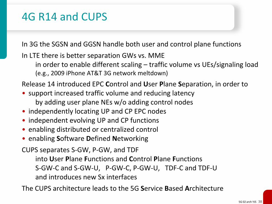
In 3G the SGSN and GGSN handle both user and control plane functions
In LTE there is better separation GWs vs. MMEin order to enable different scaling – traffic volume vs UEs/signaling load (e.g., 2009 iPhone AT&T 3G network meltdown)
Release 14 introduced EPC Control and User Plane Separation, in order to• support increased traffic volume and reducing latency
by adding user plane NEs w/o adding control nodes• independently locating UP and CP EPC nodes • independent evolving UP and CP functions• enabling distributed or centralized control• enabling Software Defined Networking
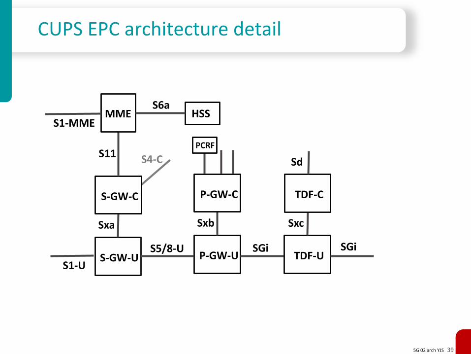
CUPS separates S-GW, P-GW, and TDFinto User Plane Functions and Control Plane Functions S-GW-C and S-GW-U, P-GW-C, P-GW-U, TDF-C and TDF-U and introduces new Sx interfaces
The CUPS architecture leads to the 5G Service Based Architecture
5G 02 arch YJS 39
CUPS EPC architecture detail
S-GW-U
Sxa
S4-C
S-GW-C
S1-UP-GW-U
Sxb
P-GW-C
S5/8-U SGiTDF-U
Sxc
TDF-C
Sd
SGi
MME
S11
S1-MME
S6aHSS
PCRF
5G 02 arch YJS 40
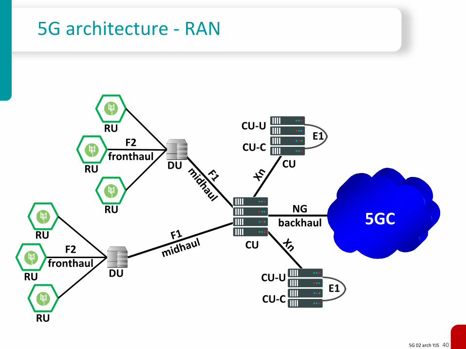
5G architecture - RAN
F2fronthaul
DU
CU
RU
DU
NGbackhaul 5GC
F2fronthaul
RU
RU
RU
RU
RU
CU
CU-C
E1
E1CU-U
CU-C
CU-U
5G 02 arch YJS 41
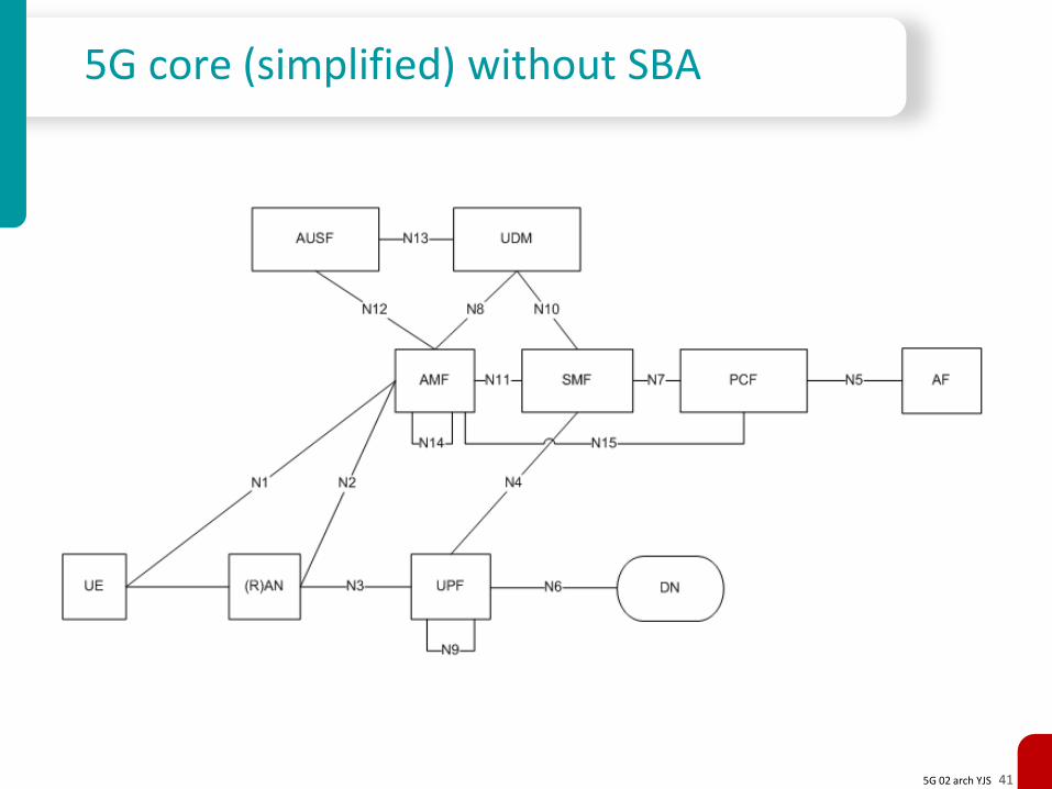
5G core (simplified) without SBA
5G 02 arch YJS 42
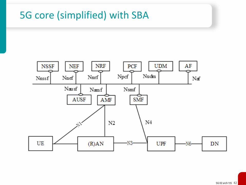
5G core (simplified) with SBA