Embed Size (px)
Citation preview

Air Guidance Note (AG8) December 2012
Page 1 of 56
Environmental Protection Agency Office of Environmental Enforcement (OEE)
Air Guidance Note for
In-house Air Monitoring Teams (AG8)
December 2012
Environmental Protection Agency Johnstown Castle Estate
Wexford, Ireland
Air Guidance Note (AG8) December 2012
Page 2 of 56
Acknowledgements
This document has been prepared on behalf of the Environmental Protection Agency by:
Stuart Newstead, Newstead Consulting Ltd. (UK)
With the assistance of: Simon Medhurst, Smedstack Environmental (UK)
The following members of Agency staff were involved in the review of this guidance note:
• Mr Tony Dolan • Dr Ian Marnane • Mr Ken Murphy • Mr Kieran Fahey
Air Guidance Note (AG8) December 2012
Page 3 of 56
Contents
Preface
1. Introduction
2. Background
3. How to use this guidance
Annex A: A model quality manual - minimum requirements for in-house stack emissions test laboratories at IPPC licensed sites Annex B: A model procedure for measurements using a portable automated measuring system (AMS) to a standard method. Annex C: A model procedure for manual extractive sampling to a standard method. References
Air Guidance Note (AG8) December 2012
Page 4 of 56
Preface
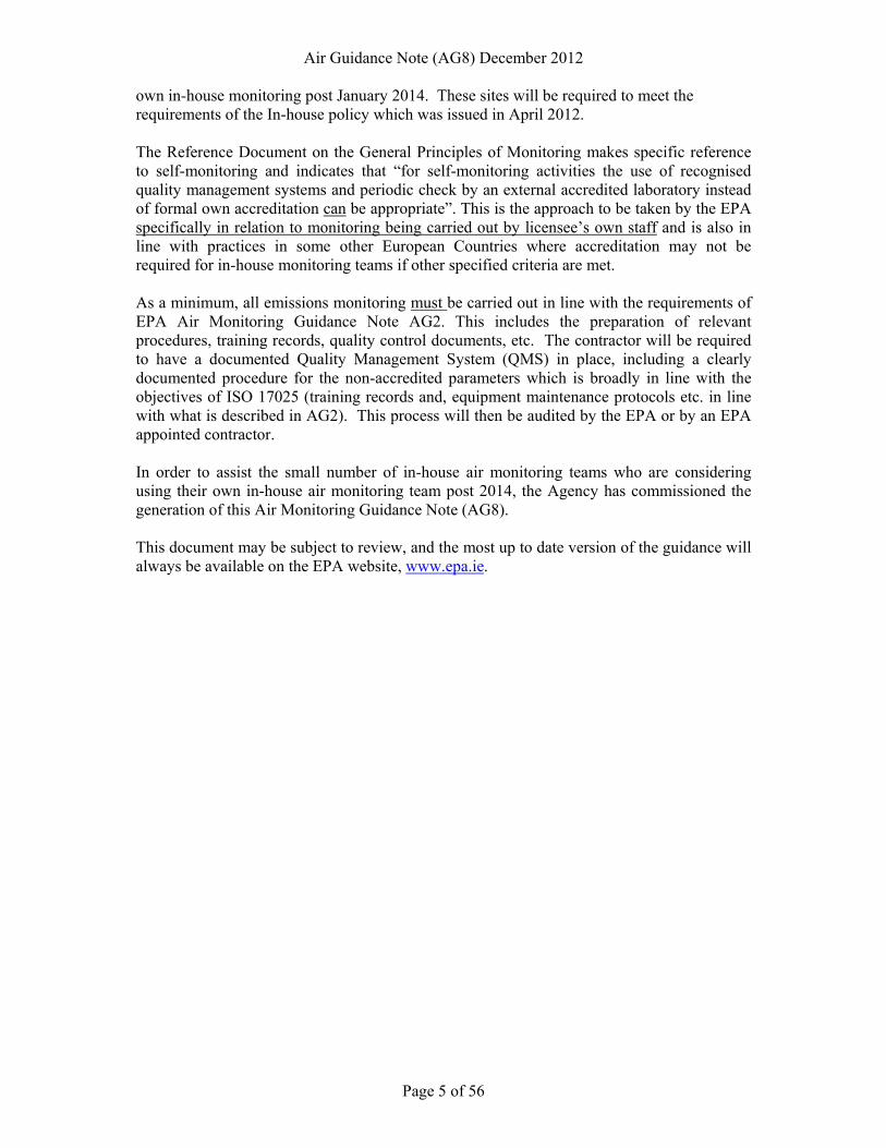
The Office of Environmental Enforcement (OEE) is an Office within the Environmental Protection Agency (EPA or Agency) dedicated to the implementation and enforcement of environmental legislation in Ireland. The Agency was aware that there were no mandatory minimum criteria specified in relation to the completion of stationary source waste gas monitoring at EPA licensed sites. This is a different situation to other European countries, where industrial air emissions monitoring at licensed/permitted sites is required to be carried out by ISO17025 accredited organisations. In addition, the use of accredited service providers is also regarded as best practice in the Reference Document on the General Principles of Monitoring This document is currently under review by the European IPPC Bureau and it is expected that references to the use of accredited monitoring contractors will be further strengthened. This is important in the context of the new Industrial Emissions Directive (2010/75/EC) which replaces existing legislation including the IPPC Directive and seeks to bring more consistency to regulation across the EU. In early 2012, the Board of the Agency approved a policy document which sets out the minimum requirements in relation to ISO 17025 accreditation for air monitoring contractors operating in Ireland. In order to ensure the generation of consistent high quality and robust stationary source emissions monitoring data from EPA licensed sites, the EPA has specified minimum acceptable criteria on this monitoring from January 1 2014 as follows: By January 2014, all air contractors carrying out monitoring of IPPC & waste licensed sites in Ireland must be accredited to ISO 17025 (with reference to IS EN 15259 and TS 15675) for the following parameters, as a minimum:
Must be accredited Jan 2014
Must be accredited Jan 2015
QMS & documented procedures
Parameters - Total particulates (low & high range),
- NOX, SO2, CO, - VOC (by FID), - Velocity and temp, - dioxins - oxygen, - moisture,
- HCL - formaldehyde - Metals - TOC as (C) - Speciated Organic
carbon ex. TA Luft organics (I, II, III)
- mercaptans, - Hydrogen
sulphide, amines, - CVOC’s, phenol - Total aldehydes - Isocyanate,
Methanol, MDI - Bioaerosols,
MIBK - Isopropanol - Isopropyl acetate - PM10 PM2.5 others - Total acids? - HF, - ammonia
The objective of requiring monitoring by accredited contractors is to generate better quality data and better quality reporting. However, there are a very small number of IPPC sites who have indicated to the Agency that there current preference is to continue to carry out their
Air Guidance Note (AG8) December 2012
Page 5 of 56
own in-house monitoring post January 2014. These sites will be required to meet the requirements of the In-house policy which was issued in April 2012. The Reference Document on the General Principles of Monitoring makes specific reference to self-monitoring and indicates that “for self-monitoring activities the use of recognised quality management systems and periodic check by an external accredited laboratory instead of formal own accreditation can be appropriate”. This is the approach to be taken by the EPA specifically in relation to monitoring being carried out by licensee’s own staff and is also in line with practices in some other European Countries where accreditation may not be required for in-house monitoring teams if other specified criteria are met. As a minimum, all emissions monitoring must be carried out in line with the requirements of EPA Air Monitoring Guidance Note AG2. This includes the preparation of relevant procedures, training records, quality control documents, etc. The contractor will be required to have a documented Quality Management System (QMS) in place, including a clearly documented procedure for the non-accredited parameters which is broadly in line with the objectives of ISO 17025 (training records and, equipment maintenance protocols etc. in line with what is described in AG2). This process will then be audited by the EPA or by an EPA appointed contractor. In order to assist the small number of in-house air monitoring teams who are considering using their own in-house air monitoring team post 2014, the Agency has commissioned the generation of this Air Monitoring Guidance Note (AG8). This document may be subject to review, and the most up to date version of the guidance will always be available on the EPA website, www.epa.ie.
Air Guidance Note (AG8) December 2012
Page 6 of 56
Air Guidance Note (AG8) December 2012
Page 7 of 56
1. Introduction This Technical Guidance Note (TGN) is one of a series published by the EPA that provides guidance on the measurement of atmospheric emissions from industrial sites licensed under Integrated Pollution & Prevention Control legislation. In March 2012 the EPA published a policy statement [1] defining its minimum acceptable criteria for atmospheric emissions monitoring that must be met from January 2014 onwards. These criteria have been set to ensure that measurements provide robust and consistently high quality results in which both the EPA and the public can have confidence.
The EPA policy statement recognises that periodic measurements of atmospheric emissions are carried out by both commercial test houses acting under contracts to IPPC site operators and by in-house teams. The policy requires commercial test houses to be accredited to IS EN ISO/IEC 17025:2005 [2] (hereafter shortened to ISO 17025) for the periodic measurement of certain pollutants from January 2014. For in-house teams accreditation to ISO 17025 is not obligatory. Instead, any licensee proposing to monitor emissions to atmosphere from a licensed emission point for assessment of compliance with a licence emission limit value must, by the 1st January 2014, have a recognised quality management system (QMS) in place and notify the EPA, using a standard form available from the Agency, of:
• The scope of monitoring proposed to be carried out by the licensee. • The parameters to be monitored at each emission point. • The methods to be used. • The expertise of the personnel carrying out the monitoring. • Any external analytical requirements. • The frequency of monitoring.
This TGN provides guidance on how to develop a QMS modelled on ISO 17025 that should meet the Agency’s minimum requirements for in-house monitoring. It also provides the basis on which the EPA will audit an operator’s conformance with its policy requirements.
2. Background
ISO 17025 defines general requirements for the competence of testing and calibration laboratories. It is applicable to all laboratories regardless of the number of personnel or the extent of scope of testing and/or calibration activities. It can be used by laboratories to develop a management system for quality, administrative and technical systems that govern their operations. Some clauses may not always be applicable – it is dependent on the scope of a laboratory’s activities. A QMS developed in accordance with ISO 17025 should consist of a Quality Manual (QM) and supporting policies, procedures, methods and instructions. The QM should define the QMS through statements of policy, assignments of responsibility, means of implementation and available documentation. Some or all of the policies and procedures may be incorporated into the QM or held in separate files. The main parts of the QM are: • A definition of the scope of activities covered by the quality management system. • A list of any documents that are indispensable (normative references) to the application of the management system. • A list of any terms and definitions that are used within the management
system.
Air Guidance Note (AG8) December 2012
Page 8 of 56
• Details of management requirements relevant to the defined scope of activities.
• Technical requirements relevant to the defined scope of activities.
I.S. ISO 9001:2000 [3] defines the requirements for a Quality Management System (QMS). Its main purpose is to provide a system for a business to manage its operations so as to meet customers' requirements through improved customer satisfaction. It is important to understand that a QMS based on ISO 9001 is not sufficient to demonstrate the competence of a laboratory to produce technically valid data and results. However, all of the requirements of ISO 9001 that are relevant to the scope of testing and calibration services are incorporated into the Management Section of ISO 17025. (But note that clause numbering is different, and that ISO 17025 includes at its Annex A cross-references to ISO 9001) Consequently, licensees that already have a QMS based on ISO 9001 should be able to:
• Either incorporate appropriate text required by this guidance note for Sections 1 to 4 into their existing ISO 9001 QM, (but note that if their ISO 9001 QMS is certified then this additional text will also have to be certified.)
• Or, make use of aspects of their ISO 9001 QM (possible by cross-referencing to a specific section in the ISO9001 QM) when drafting a QM to meet the requirements detailed in this guidance note.
• Or, if it appears simpler, use aspects of their ISO 9001 QM when drafting a stand-alone QM to meet the requirements of this guidance note.
I.S. ISO 14001: 2004 [4] defines the requirements for an Environmental Management System (EMS). Its main purpose is to identify the impact of a business on the environment and the environmental laws that are relevant to that business. As for ISO 9001, it is important to understand that an EMS based on ISO 14001 is not sufficient to demonstrate the competence of a laboratory to produce technically valid data and results. However, ISO 14001 is compatible with ISO 9001 and therefore with the Management Requirements of ISO 17025. Consequently, licensees that already have a QMS based on ISO 14001 should be able to:
• Either incorporate appropriate text required by this guidance note for Sections 1to 4 into their existing ISO 14001 QM, (but note that if their ISO 14001 QMS is certified then this additional text will also have to be certified.
• Or, make use of aspects of their ISO 14001 QM (possible by cross-referencing to a specific section in the ISO14001 QM) when drafting a QM to meet the requirements detailed in this guidance note.
• Or, if it appears simpler, use aspects of their ISO 14001 QM when drafting a stand-alone QM to meet the requirements of this guidance note.
I.S. CEN/TS 15675:2007 [5] provides guidance on the application of EN ISO/IEC 17025:2005 to periodic measurements of emissions from industrial sources. This Technical Specification adopts a wide definition of periodic emissions measurement and its relevance therefore should be considered to all measurement activities undertaken by an in-house team.
I.S. EN 15259:2007 [6] defines requirements for establishing measurement sections
and sites at waste gas ducts on industrial plants; and for determining the objective, developing a plan and reporting the results of emissions monitoring. It specifies
Air Guidance Note (AG8) December 2012
Page 9 of 56
generic principles that are designed to meet different measurement objectives applicable to both manual and automated measurements at a range of plants It is therefore a core standard for developing the technical requirements of a QMS related to the application of measurement methods.
EPA Air Monitoring Guidance Note AG1 [7] provides guidance on the sampling facilities which the licensee should provide to permit the safe and effective measurement of emissions to air. It makes specific reference to the adoption of EN 15259 within the Irish regulatory system.
EPA Air Monitoring Guidance Note AG2 [8] provides guidance on the many aspects of stack emissions monitoring that contribute to the quality of data. In particular it provides an Index of Preferred Methods for the determination of stack emissions.
Additionally, the UK Environment Agency has published a series of Technical Guidance Notes (TGN M) on monitoring, and several Standards under its Monitoring Certification Scheme (MCERTS). TGNs M1 & M2 [9 & 10] and the MCERTS documents which set out: (a) Performance requirements for laboratories carrying out stack emissions monitoring [11], (b) Personnel competency standard for manual stack-emission monitoring [12] and Method Implementation Documents [13] are relevant to this guidance note.
3. How to use this guidance
Annex A sets out a model QM that includes the EPA’s minimum requirements for in-house monitoring. Annexes B and C provide model procedures for measurements using a portable automated measuring system (AMS) to a standard method, and for manual extractive sampling to a standard method respectively. Note that the models for procedures do not follow exactly the same formats. This is to illustrate that these models are not prescriptive and should be customised to meet specific applications.
The model QM must be read in conjunction with ISO 17025 as the requirements of that standard are not repeated in this guidance note. To make cross reference easy the model broadly follows the structure of ISO 17025 with consistent numbering and titles for sections and clauses, although some sections and clauses have been compressed. It does not provide an off-the-shelf QM or a set of policies, procedures, methods and instructions. Rather it provides a structure and guides the reader through the issues that must be addressed. The EPA’s minimum requirements are specified under each section or clause heading. In most cases this is supported by guidance (in blue coloured boxes) on how to address the requirements. This includes directions to relevant text in the source documents listed above. The model also indicates where requirements of ISO 17025 are unlikely to be relevant to in-house laboratories. However, a generic guidance document of this type cannot cover every eventuality so the licensee must consider whether or not each of these requirements is relevant to their specific purposes.
The model procedures follow a similar approach but minimum requirements are not stated as these will vary with the measurement method. At each section a high level statement of what needs to be done is entered. In most cases this is supported by guidance (in blue coloured boxes) on how to address the requirements. Procedures not related to the implementation of standard measurement methods will follow a different format.
Air Guidance Note (AG8) December 2012
Page 10 of 56
A QM is likely to be about the same length as the model (i.e. ~30 pages). It is worth taking some time at the start to think about the overall structure of a QM - the policies, procedures and instructions and how many of each will be required. If they are short and not required on a daily basis they are best incorporated into the QM. If they are longer it is advisable to provide cross references to separate documents held in separate files.
As a guide, when drafting the QM, most entries under the given clause headings should not exceed half a page. Policy statements are also unlikely to exceed half a page. Procedures, particularly those associated with the implementation of standard measurement methods can be extensive (e.g.12 pages each). It is important to recognise that the role of documented in-house technical procedures is to provide clear, unambiguous instructions to staff so that technical work can be performed repeatability even if carried out by different staff at different times. They are not a restatement of published standard measurement methods but need to describe in as much detail as necessary how the requirements of the standard will be met.
The amount of time required is difficult to advise as it will vary with the number of: emission points, measurement methods, instruments, items of equipment and personnel involved in carrying out the emissions monitoring. However, to give some tentative indication: anyone who is unfamiliar with drafting quality documentation might take up to six months to complete a QMS, whereas someone with experience might do so within a month.
Air Guidance Note (AG8) December 2012
Page 11 of 56
Quality Manual
ANNEX A A MODEL QUALITY MANUAL FOR IN-HOUSE
STACK EMISSIONS TEST TEAMS AT IPPC LICENSED SITES INCLUDING THE EPA’s
MINIMUM REQUIREMENTS
Note 1: This model must be read in conjunction with ISO 17025 Note 2: If the guidance given at Section 2 Background re ISO 9001 or ISO 14001 is relevant then this model must be read in conjunction with those standards and the licencee’s existing QMs.
Air Guidance Note (AG8) December 2012
Page 12 of 56
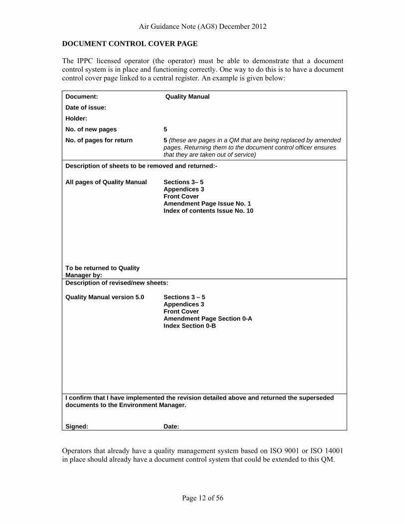
DOCUMENT CONTROL COVER PAGE The IPPC licensed operator (the operator) must be able to demonstrate that a document control system is in place and functioning correctly. One way to do this is to have a document control cover page linked to a central register. An example is given below: Document: Quality Manual
Date of issue:
Holder:
No. of new pages 5
No. of pages for return 5 (these are pages in a QM that are being replaced by amended pages. Returning them to the document control officer ensures that they are taken out of service)
Description of sheets to be removed and returned:- All pages of Quality Manual Sections 3– 5 Appendices 3 Front Cover Amendment Page Issue No. 1 Index of contents Issue No. 10 To be returned to Quality Manager by: Description of revised/new sheets: Quality Manual version 5.0 Sections 3 – 5 Appendices 3 Front Cover Amendment Page Section 0-A Index Section 0-B I confirm that I have implemented the revision detailed above and returned the superseded documents to the Environment Manager. Signed: Date:
Operators that already have a quality management system based on ISO 9001 or ISO 14001 in place should already have a document control system that could be extended to this QM.
Air Guidance Note (AG8) December 2012
Page 13 of 56
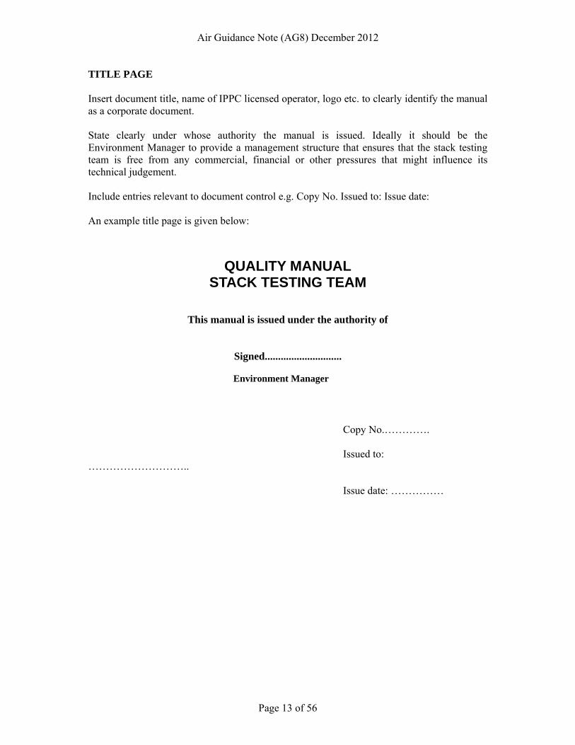
TITLE PAGE Insert document title, name of IPPC licensed operator, logo etc. to clearly identify the manual as a corporate document. State clearly under whose authority the manual is issued. Ideally it should be the Environment Manager to provide a management structure that ensures that the stack testing team is free from any commercial, financial or other pressures that might influence its technical judgement. Include entries relevant to document control e.g. Copy No. Issued to: Issue date: An example title page is given below:
QUALITY MANUAL
STACK TESTING TEAM
This manual is issued under the authority of
Signed.............................
Environment Manager Copy No.…………. Issued to: ……………………….. Issue date: ……………
Air Guidance Note (AG8) December 2012
Page 14 of 56
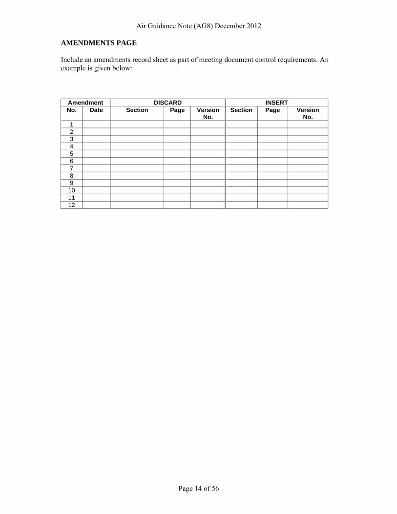
AMENDMENTS PAGE Include an amendments record sheet as part of meeting document control requirements. An example is given below:
Amendment DISCARD INSERT No. Date Section Page Version
No. Section Page Version
No. 1 2 3 4 5 6 7 8 9 10 11 12
Air Guidance Note (AG8) December 2012
Page 15 of 56
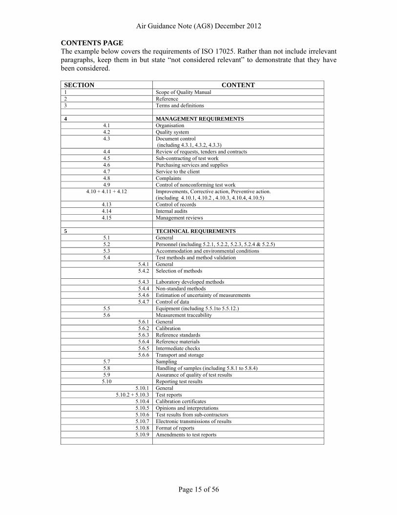
CONTENTS PAGE The example below covers the requirements of ISO 17025. Rather than not include irrelevant paragraphs, keep them in but state “not considered relevant” to demonstrate that they have been considered. SECTION CONTENT1 Scope of Quality Manual 2 Reference 3 Terms and definitions 4 MANAGEMENT REQUIREMENTS
4.1 Organisation 4.2 Quality system 4.3 Document control
(including 4.3.1, 4.3.2, 4.3.3) 4.4 Review of requests, tenders and contracts 4.5 Sub-contracting of test work 4.6 Purchasing services and supplies 4.7 Service to the client 4.8 Complaints 4.9 Control of nonconforming test work
4.10 + 4.11 + 4.12 Improvements, Corrective action, Preventive action. (including 4.10.1, 4.10.2 , 4.10.3, 4.10.4, 4.10.5)
4.13 Control of records 4.14 Internal audits 4.15 Management reviews
5 TECHNICAL REQUIREMENTS
5.1 General 5.2 Personnel (including 5.2.1, 5.2.2, 5.2.3, 5.2.4 & 5.2.5) 5.3 Accommodation and environmental conditions 5.4 Test methods and method validation
5.4.1 General 5.4.2 Selection of methods
5.4.3 Laboratory developed methods 5.4.4 Non-standard methods
5.4.6 Estimation of uncertainty of measurements 5.4.7 Control of data
5.5 Equipment (including 5.5.1to 5.5.12.) 5.6 Measurement traceability
5.6.1 General5.6.2 Calibration 5.6.3 Reference standards 5.6.4 Reference materials 5.6.5 Intermediate checks 5.6.6 Transport and storage
5.7 Sampling 5.8 Handling of samples (including 5.8.1 to 5.8.4) 5.9 Assurance of quality of test results 5.10 Reporting test results
5.10.1 General5.10.2 + 5.10.3 Test reports
5.10.4 Calibration certificates 5.10.5 Opinions and interpretations 5.10.6 Test results from sub-contractors 5.10.7 Electronic transmissions of results 5.10.8 Format of reports 5.10.9 Amendments to test reports
Air Guidance Note (AG8) December 2012
Page 16 of 56
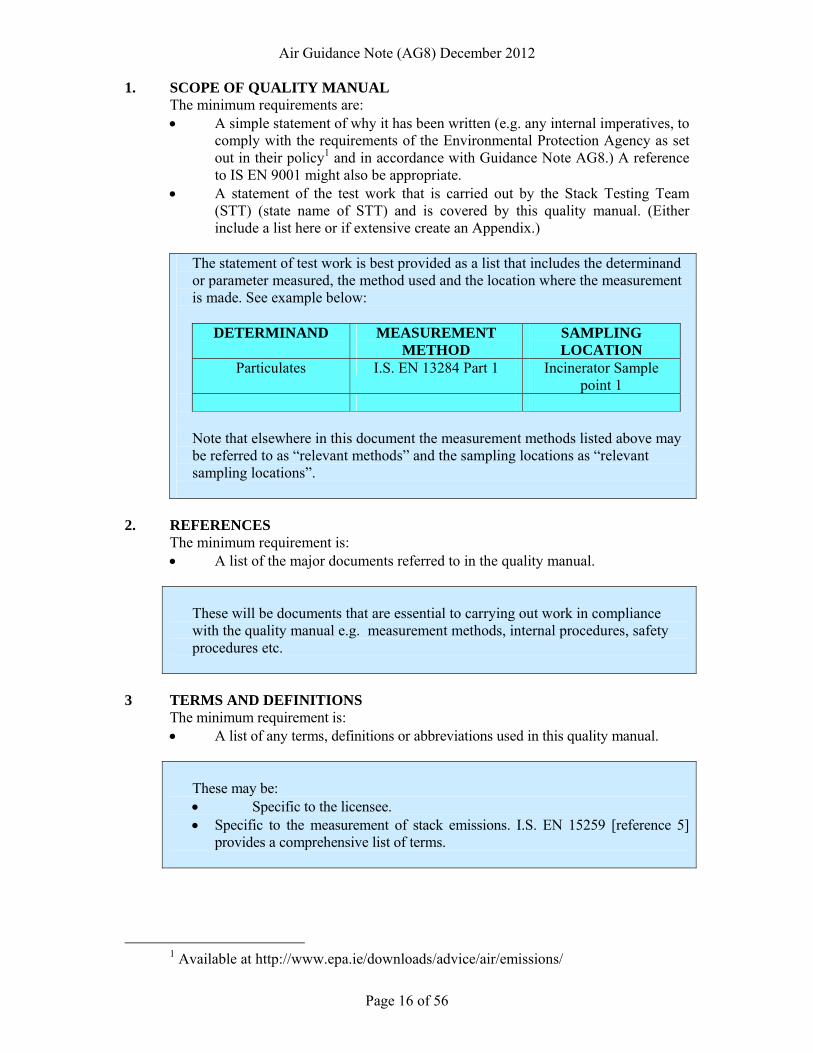
1. SCOPE OF QUALITY MANUAL The minimum requirements are:
• A simple statement of why it has been written (e.g. any internal imperatives, to comply with the requirements of the Environmental Protection Agency as set out in their policy1 and in accordance with Guidance Note AG8.) A reference to IS EN 9001 might also be appropriate. • A statement of the test work that is carried out by the Stack Testing Team (STT) (state name of STT) and is covered by this quality manual. (Either include a list here or if extensive create an Appendix.)
The statement of test work is best provided as a list that includes the determinand or parameter measured, the method used and the location where the measurement is made. See example below:
DETERMINAND MEASUREMENT
METHOD SAMPLING LOCATION
Particulates I.S. EN 13284 Part 1 Incinerator Sample point 1
Note that elsewhere in this document the measurement methods listed above may be referred to as “relevant methods” and the sampling locations as “relevant sampling locations”.
2. REFERENCES The minimum requirement is: • A list of the major documents referred to in the quality manual.
These will be documents that are essential to carrying out work in compliance with the quality manual e.g. measurement methods, internal procedures, safety procedures etc.
3 TERMS AND DEFINITIONS The minimum requirement is: • A list of any terms, definitions or abbreviations used in this quality manual.
These may be: • Specific to the licensee. • Specific to the measurement of stack emissions. I.S. EN 15259 [reference 5]
provides a comprehensive list of terms.
1 Available at http://www.epa.ie/downloads/advice/air/emissions/
Air Guidance Note (AG8) December 2012
Page 17 of 56
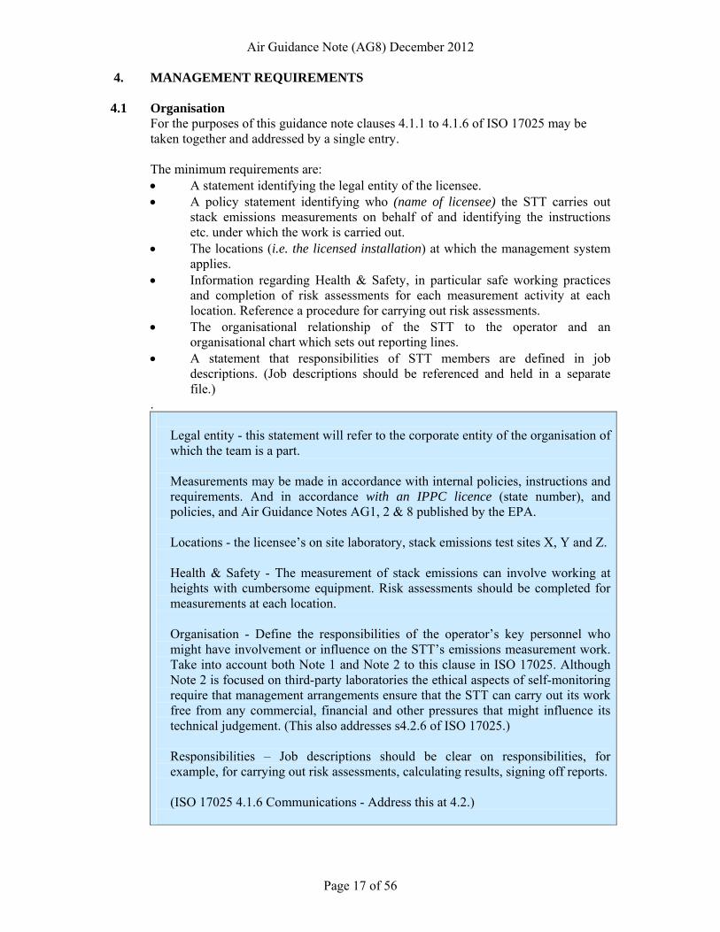
4. MANAGEMENT REQUIREMENTS
4.1 Organisation For the purposes of this guidance note clauses 4.1.1 to 4.1.6 of ISO 17025 may be taken together and addressed by a single entry. The minimum requirements are: • A statement identifying the legal entity of the licensee. • A policy statement identifying who (name of licensee) the STT carries out
stack emissions measurements on behalf of and identifying the instructions etc. under which the work is carried out.
• The locations (i.e. the licensed installation) at which the management system applies.
• Information regarding Health & Safety, in particular safe working practices and completion of risk assessments for each measurement activity at each location. Reference a procedure for carrying out risk assessments.
• The organisational relationship of the STT to the operator and an organisational chart which sets out reporting lines.
• A statement that responsibilities of STT members are defined in job descriptions. (Job descriptions should be referenced and held in a separate file.)
.
Legal entity - this statement will refer to the corporate entity of the organisation of which the team is a part. Measurements may be made in accordance with internal policies, instructions and requirements. And in accordance with an IPPC licence (state number), and policies, and Air Guidance Notes AG1, 2 & 8 published by the EPA. Locations - the licensee’s on site laboratory, stack emissions test sites X, Y and Z.
Health & Safety - The measurement of stack emissions can involve working at heights with cumbersome equipment. Risk assessments should be completed for measurements at each location. Organisation - Define the responsibilities of the operator’s key personnel who might have involvement or influence on the STT’s emissions measurement work. Take into account both Note 1 and Note 2 to this clause in ISO 17025. Although Note 2 is focused on third-party laboratories the ethical aspects of self-monitoring require that management arrangements ensure that the STT can carry out its work free from any commercial, financial and other pressures that might influence its technical judgement. (This also addresses s4.2.6 of ISO 17025.)
Responsibilities – Job descriptions should be clear on responsibilities, for example, for carrying out risk assessments, calculating results, signing off reports.
(ISO 17025 4.1.6 Communications - Address this at 4.2.)
Air Guidance Note (AG8) December 2012
Page 18 of 56
4.2 Management system For the purposes of this guidance note clauses 4.2.1 to 4.2.7 (including 4.1.6) of ISO 17025 may be taken together and addressed by a single entry.
The minimum requirements are: • A short description of the management system (e.g. QM, policies, procedures,
methods, instructions, site data sheets, electronic data recording/storage etc.) that is used to control the scope of work stated at 1 above.
• A quality policy statement. • A policy statement confirming management’s commitment to the requirement
specified at 4.2.3 in ISO 17025. • Provide a statement here about how management communicates to the STT
the importance of meeting the requirements of internal interested parties and the EPA.
• All systems change and if the changes are not controlled the management system will decay over time. State briefly here the arrangements (e.g. change procedure) that management have in place to maintain the management system
Management system - Include anything here that is pertinent to “assuring the quality of the test and/or calibration results”. Exclude matters not relevant to quality of results. Provide a description of structure and content of the management system. For example the management system is likely to include this quality manual, policy statements, procedures, instructions, standard methods, calibration certificates or data sheets, computer programmes for calculation of results, pro-forma forms etc. (This also addresses 4.1.6.) Quality policy - This should address sub-clauses a) to e) of 4.2.2 in ISO 17025. Take into account the Note at 4.2.2 in ISO 17025 re the policy being concise, use of standard methods to meet the operator’s and the EPA’s requirements. An example of standard of service could be: “…quality results based on the use of European measurement methods in accordance with our internal procedures…”. It should be issued under the authority of a senior manager (e.g. managing director). Management commitment - Evidence could be: management reviews of the effectiveness of the management system, meeting minutes, training records, management instructions. This could include issuing of documents, briefing notices and meetings, company training, periodic review meetings involving all personnel involved in emissions monitoring. Communications - State how this documentation is communicated to appropriate personnel. Maintenance of management system - This could include: • Scheduled management reviews of the effectiveness of the management
system. • Reviews prompted by external complaints, EPA audits, or internal concerns. • On-going communications and the routine activities of the quality manager.
Air Guidance Note (AG8) December 2012
Page 19 of 56
4.3 Document control For the purposes of this guidance note clauses 4.3.1 to 4.3.3 of ISO 17025 may be taken together and addressed by a single entry.
The minimum requirement is:
• A description of how documents (either internally generated or from external sources) are approved, issued and controlled, and the arrangements for reviewing documents, making revisions and controlling changes.
Documents - Internally generated documents include: policy statements, procedures, in-house calibrations. Externally generated documents, include: standard methods, calibration certificates equipment operating instructions, computer programmes.
Approval, issue, review, revision & control – Describe: • How extant documents are reviewed and approved and by whom. • Where within the QMS a master list of documents and a list recording the
distribution of documents to personnel (i.e. Who has what?) can be found. • How a list of controlled documents is maintained (e.g. version numbers, issue
dates, to whom issued, page numbers, total number of pages, and the issuing authority. Cross-reference the document control cover sheet and amendments page.
• Where authorised editions of documents are kept (e.g. master in Environmental Manager’s office, copies with STT members. Where the master is held on a computer server, all printed copies are uncontrolled.).
• The arrangements for reviewing documents and making revisions. • How invalid or obsolete/superseded documents are removed from the
management system. • How invalid or obsolete/superseded documents are retained but marked to
avoid their mistaken use as current documents. • Whose responsibility it is to ensure that the amendment procedure is
correctly followed. • Who can initiate amendments. • Who can approve amendments. • How revised text or new text is identified. (This could be by using an
amendment sheet at the front of each document and highlighting or marking with a vertical line in the right hand margin any altered text.)
• State if the document control system allows for hand amendments (i.e. hand written changes) pending issue of revised documents. If so describe how hand amendments are reviewed and revisions authorised.
• How versions of software (e.g. spreadsheets for compiling emissions data) should be used and kept under the control of an authorised person. (The spreadsheets should be password protected by the authorised person and stored on computers as read-only files. Changes can then only be made by the authorised person.)
Air Guidance Note (AG8) December 2012
Page 20 of 56
4.4 Review of requests, tenders and contracts
It is unlikely that these requirements will be relevant to in-house STTs.
This clause may be applicable where a large organisations with a multiplicity of sites but a centralised stack emission monitoring function. Under these circumstances, meeting the principal procedural requirements of ISO 17025 (clause 4.4) with respect to review of requests might be appropriate.
4.5 Subcontracting of tests and calibrations
For the purposes of this guidance note clauses 4.5.1 to 4.5.4 of ISO 17025 may be taken together and addressed by a single entry.
The minimum requirements are:
• A statement of who is responsible for the work of any sub-contractor. • A statement that a register of approved sub-contractors is maintained, including
who maintains the register and where it is kept.
This clause will only apply if external sub-contractors are employed to carryout work that otherwise might be undertaken by the in-house STT. This may arise if the STT cannot undertake the required work because of staff shortages or because it requires specialist expertise or equipment not available to the STT. EPA policy [1] requires that any external contractor to whom stack emissions measurements are sub-contracted should be ISO 17025 accredited for the relevant measurement methods. The statement should recognise this requirement.
The “customer” (see 4.5.2 of ISO 17015) will be the internal interested party
4.6 Purchasing services and supplies
For the purposes of this guidance note clauses 4.6.1 to 4.6.4 of ISO 17025 may be taken together and addressed by a single entry. The minimum requirement is: • A statement of how services and supplies are selected and purchased.
EPA policy [1] requires that sub-contractors used for analytical work or for the calibration of equipment, should be accredited to ISO 17025 for the relevant methods or if no accredited laboratories exist for a particular determinand or calibration, then a suitable competent calibration laboratory must be used e.g. one of known quality through previous use or one that has been assessed by the STT. A statement echoing this requirement should be entered here.
Include a full description of how purchasing in the statement or reference a procedure as a separate document). The statement should refer to quality requirements (e.g. I.S. ISO 9000 and/or quality specifications), and responsibilities for procurement.
Air Guidance Note (AG8) December 2012
Page 21 of 56
Requirements and checks should be carried out to ensure that new suppliers can offer goods and services of the required quality before purchase. (e.g. certification to I.S. ISO 9001, checked by audit).
Purchasing documents should specify appropriate technical data e.g. grade, specification, quality control.
A register of critical suppliers should be maintained. Procedures for accepting, checking and storing supplies should be available.
4.7 Service to the customer
For the purposes of this guidance note clauses 4.7.1 and 4.7.2 of ISO 17025 may be taken together and addressed by a single entry. This requirement will only apply where there is a clearly identifiable customer for the STT’s services. This is most likely to arise where a STT undertakes work at more than one site within the parent company’s control. If there is no identifiable internal customer this clause in ISO 17025 may be considered inapplicable. If the clause is applicable the minimum requirement is: • A statement of how the STT clarifies the customer’s requirements and engages
with the customer to seek feedback on its performance of the emissions measurement work
Note that the EPA is not a customer.
4.8 Complaints
Complaints in the context of this guidance arise from an internal customer (e.g. when the in-house team is sampling at a number of different company sites). They do not include regulatory actions or audits undertaken by the EPA. If there is no identifiable internal customer see 4.7 above then this clause in ISO 17025 may be considered inapplicable.
If the clause is applicable the minimum requirement is:
• A policy statement that also references a separate procedure for dealing with complaints
The policy and procedure should address how complaints are addressed. The procedure should include: • Assignment of responsibility for dealing with complaints. • Arrangements for recording complaints (e.g. in a Customer Feedback File),
including details of the complaint, the action proposed to resolve the complaint, the action taken, and communication(s) with the complainant.
• Arrangements for addressing cases of serious complaint that could call into question the validity of the final test results. Where it is thought likely that the validity of test work is in doubt, the internal customer and the EPA should be notified and kept informed of any remedial action that may become necessary.
Air Guidance Note (AG8) December 2012
Page 22 of 56
• Remedial action might include additional audits, amendments to reports, or repeating the test work.
4.9 Control of nonconforming testing and/or calibration work
For the purposes of this guidance note clauses 4.9.1 and 4.9.2 of ISO 17025 may be taken together and addressed by a single entry. The minimum requirement is: • A statement of how non-conforming work will be handled and a procedure
detailing the arrangements.
Nonconforming test work can occur at various places e.g. incorrect following of documented test procedures, use of un-calibrated test equipment, lack of staff supervision or training, errors in test report. Nonconforming test work may be identified by STT staff or managers, or by the internal client, or the EPA. But note that the term ‘nonconforming’ is not a reference to a non-compliant emission from the point of view of licence compliance.
The procedure should include: • Arrangements for, defining, identifying and recording nonconformities. • An evaluation of the significance of the non-conforming work. • Who is responsible for investigating the non-conformity. • Criteria for deciding whether or not to halt the work or declare the result
invalid. • Arrangements for corrective action and for restarting or repeating the work. • The circumstances under which invalid test work should be repeated.
4.10 Improvement, 4.11 Corrective action and 4.12 Preventive action For the purposes of this guidance note clauses 4.10, 4.11 and 4.12 and their sub-clauses of ISO 17025 may be taken together and addressed by a single entry. The minimum requirements are: • A short policy statement that addresses the requirements for continuous
improvement. • A policy statement of how corrective actions will be carried out and a
procedure detailing the arrangements. • A policy statement of how preventive actions will be carried out.
Continuous improvement - the statement should refer to scheduled and responsive reviews undertaken by management of the effectiveness of the management system using the tools listed at 4.10 in ISO 17025. Given the repetitive nature of in-house testing the scope for improvement may be limited. It is unlikely that a procedure will be required. Corrective actions – the statement should refer to: cause analysis, selection and implementation of corrective actions, monitoring of corrective actions, and additional audits (see 4.11.2 to 4.11.5).
Air Guidance Note (AG8) December 2012
Page 23 of 56
Corrective actions – the procedure should:
• Designate the person who is responsible for implementing corrective actions. • Take account of the Note at 4.11.2 in ISO 17025. • Provide a means to select corrective actions (i.e. those most likely to eliminate
the problem.) Note that actions should be proportionate to the magnitude and risk of the problem, so keep it simple. To what extent is the result rendered invalid?
• Provide a means for recording the instigation and closing out of corrective actions, and for assessing the effectiveness of corrective actions (e.g. judged by monitoring the quality of on-going work).
• Additional audits should not be necessary so this clause may be identified as not applicable.
• Be also applicable to the requirement for corrective actions etc. with respect to internal audits (see 4.14 below).
Preventive actions – the statement could refer to periodic checks, or audits, carried out by the STT on its own activities, to verify that its operations continue to comply with the requirements of this quality manual, and the documented procedures and ISO 17025. It is unlikely that a procedure will be required.
4.13 Control of records (4.13.1 & 4.13.2)
For the purposes of this guidance note clauses 4.13.1 to 4.13.2 and their sub-clauses of ISO 17025 may be taken together and addressed by a single entry. The minimum requirement is: • A single policy statement that the organisation will maintain a systematic and
documented record system based on the guidance provided in Technical Guidance Note AG8 and cross-reference to a procedure detailing the arrangements for implementing this policy
Procedure – This should: • Address all of the points listed at 4.13.1.1 in ISO 17025. • State the types of records and the form in which they are kept and
arrangements for their safe keeping. (Records may include: pro-forma datasheets, laboratory notebooks, a log book, outputs from continuous analysers that may be downloaded electronically. Records may be kept in mobile laboratories, main laboratories, and offices.)
• State how records are kept (i.e. paper, electronic), under the supervision of a designated person to safeguard security and confidentiality.
• Address all of the points listed at 4.13.1.4 in ISO 17025. • Address all of the points made at 4.13.2.1 in ISO 17025 including the Notes. • Detail how observations etc. (see 4.13.2.2) are made identifiable to the task
e.g. by use of assigned individual job numbers printed on log books and datasheets.
Address all of the points listed at 4.13.2.3 in ISO 17025. Also see the guidance at 4.3.3. Data recorded or stored electronically should be subject to the same safeguards to avoid loss or change to original data.
Air Guidance Note (AG8) December 2012
Page 24 of 56
4.14 Internal audits For the purposes of this guidance note clauses 4.14.1 and 4.14.2 of ISO 17025 may be taken together and addressed by a single entry.
The minimum requirements are: A policy statement that also references a procedure for carrying out internal audits.
Policy statement - State the arrangements for carrying out internal audits taking into account the details of the requirement at 4.14.1 in ISO 17025. Include: • A description of what is covered by the audit schedule. . • The frequency of carrying out audits (see the Note at 4.14.1 in ISO17025). • Who is responsible planning and carrying out audits. • The arrangements for recording the findings of audits. • The arrangements and timescales for carrying out corrective actions. • Cross-reference the procedure required at 4.11 above rather than draft a
separate procedure with regard to carrying out corrective actions, the arrangements for making and keeping records, and the arrangements for judging the effectiveness of corrective actions.
4.15 Management reviews For the purposes of this guidance note clauses 4.15.1 and 4.15.2 of ISO 17025 may be taken together and addressed by a single entry.
The minimum requirement is:
• A statement that management reviews will be carried out and a procedure describing how findings will be recorded and acted upon. (Note that all of the issues listed under these clauses should be considered when drafting the procedure but it may not be necessary to address every one.)
Reviews should be carried out once per year and findings should be recorded and fed into future planning (e.g. of the next year’s work programme). The procedure should address all of the issues listed at 4.15.1 in ISO 17025. Consider giving a typical agenda for a review meeting. State: who is responsible for organising reviews.
State how findings and actions are recorded, who is responsible for ensuring they are closed out, and how timescales are agreed (e.g. at the review meetings on a case by case basis) should be stated.
.
Air Guidance Note (AG8) December 2012
Page 25 of 56
5. TECHNICAL REQUIREMENTS 5.1 General (5.1.1 & 5.1.2)
For the purposes of this guidance note clauses 5.1.1 and 5.1.2 of ISO 17025 may be taken together and addressed by a single entry. The minimum requirement is: A simple statement describing the work done by the in-house team.
The statement should cover: what is measured, where the measurements are made, why they are made, the approach taken to achieve accuracy and minimise the uncertainties of measurements e.g. choice of measurement methods, validation if necessary, use of appropriate equipment and training of staff. It should provide a lead into the following sections.
5.2 Personnel ISO 17025 subdivides this section into five untitled subsections covering personnel competence, training, personnel status, job descriptions. and authorisations. For the purposes of this guidance note clauses 5.2.1 to 5.2.5 of ISO 17025 may be taken together and addressed by a single entry.
The minimum requirements are:
• A statement of the licensee’s competency standard(s) for its personnel carrying out stack emissions monitoring that complies with the following requirements: - All competent persons should possess a combination of technical knowledge, experience and skills relevant to the measurement method (relevant methods) listed at Section 1 Scope.
- Knowledge and understanding of the process plant, and the stack emissions from the plant, at which measurements are made as specified at Section 1 Scope.
- An in-depth understanding and experience of the relevant methods and their associated implementation procedures. - A clear understanding of the licensing requirements specified in the IPPC licence for the company’s site. - A clear understanding of all sampling equipment and instruments used when carrying out the relevant measurements. - Familiarity with any analytical methods used to analyse samples collected using the relevant methods. - An ability to perform calculations necessary to convert field data into a final result. - An ability to interpret and explain results.
• A statement regarding identifying training needs and providing training. • A statement of the employment status of the personnel carrying out the licensee’s stack emissions monitoring. • A statement that job descriptions are available for all personnel carrying out stack emissions measurements. (These may be included here or more likely reference made to a separate file.) • A statement of the means by which personnel are authorised to carry out the various activities specified in ISO 17025 that are relevant to their stack emissions measurement work.
Air Guidance Note (AG8) December 2012
Page 26 of 56
• The arrangements for record keeping: what they cover, how they are kept, where they can be found, and who is responsible for their maintenance.
Competency standards: • A competent person should be able to demonstrate his/her technical knowledge,
experience and skills during EPA audits and by reference to participation in continual professional development.
• The EPA recognises that STTs may comprise personnel with a range of competencies. Guidance Note AG2 [8] defines three levels of competency: Trainee, Technician and Team Leader.
• Further information is available in detail in IS CEN/TS 15675 [5].The “limited scope” competency requirements in the MCERTS standard [10] may be more relevant.
Training: Personnel are likely to need training to meet the licensee’s competency standard(s), and then continual professional development for both refresher purposes and to keep up with developments (e.g. introduction of a new measurement method).
Status: This guidance assumes that the personnel constituting an in-house team are permanent employees of the licensee. If, the licensee uses other non-permanent personnel, perhaps in exceptional circumstances, then this section should also state that the licensee will ensure that these staff can meet the requirements of this section of their quality manual.
Job descriptions: ISO 17025 recognises that job descriptions may be required for managerial, technical and key support staff. For personnel carrying out stack emissions measurements job descriptions should correspond to the licensee’s stated competency standards.
Authorisations – These may be stated in the job descriptions or take the form of a generic procedure.
Records should cover all the matters specified in ISO 17025 and elaborated in accordance with the guidance above for 5.2.1 to 5.2.4. They might, for example, be kept in an appropriately labelled file, in a labelled filing cabinet in a specified office and maintained by the Environment Manager.
5.3 Accommodation and environmental conditions ISO 17025 subdivides this section into five untitled subsections. This TGN derives titles for the subsections based on the relevant requirements described in ISO 17025.
5.3.1 Laboratory facilities & 5.3.2 Environmental conditions For the purposes of this guidance note clauses 5.3.1 to 5.3.2 of ISO 17025 may be taken together and addressed by a single entry.
The minimum requirement is:
Air Guidance Note (AG8) December 2012
Page 27 of 56
• A statement of the locations at which measurements are made and of the environmental conditions that pertain at these locations and any measures that need to be taken to manage these conditions.
Locations - this information will already have been given at Section 1 Scope but the entry here should also include the laboratory to which samples are taken for analysis as well as the stack locations. A fuller description should be given here taking into account the technical and environmental requirements given in the EPA’s Guidance Note AG1 [7] and the additional information available in I.S. EN 15259 [6].
Accommodation & environmental conditions: • These source documents should be used to produce (a) statement(s) as
required by ISO 17025 of the technical requirements for accommodation and environmental conditions that can affect the results of stack emissions monitoring.
• Any deviations from the requirements specified in these statements that might prevent correct performance of a measurement method, (e.g. access restricted to one port only), should be recorded.
• The statement should make clear that the effect of environmental conditions a (e.g. ambient temperature) will be managed appropriately.
5.3.3 Separation of work areas
The minimum requirement is: • A statement identifying and assessing the risk of contamination at sampling
locations and within mobile and permanent laboratories and include or cross reference to a separate policy.
Sample handling on the stack sampling platform can pose a significant risk of cross-contamination from incompatible activities in neighbouring areas. These risks should be evaluated for each location and procedures produced to minimise these risks in accordance with the source documents referenced above at 5.3.1 & 5.3.2. These procedures may include: • Erecting physical barriers to cordon off or isolate the stack sampling platform. • Creation of a clean area for setting up equipment, handling samples, and for
storing equipment. • Details on for the safe handling of samples and sampling equipment.
As it may be necessary to use these procedures on site it may be best to reference here a separate document.
5.3.4 Control of access to work areas
The minimum requirement is: • A statement of how access to work areas is restricted.
Air Guidance Note (AG8) December 2012
Page 28 of 56
Access to and use of the stack sampling platform and mobile laboratory should be restricted to essential personnel. This may require physical barriers to be erected and appropriate signage displayed. Requirements should be included in the procedures called for at 5.3.3.
5.3.5 Good housekeeping The minimum requirement is: • A statement that each location will be assessed and arrangements made to keep the
stack sampling platform, clean area, and mobile laboratory free from hazards and obstacles and clean in order to minimise the risk of cross-contamination. (These arrangements could be detailed in the procedures called for at 5.3.3.)
5.4 Test and calibration methods and method validation
5.4.1 General
The minimum requirement is: • A policy statement that commits the STT to using methods which are fit for
purpose and addresses: - The measurement methods being used. - Measurement uncertainty. - The equipment being used. - How methods and instructions are kept up to date. - How methods, instructions and procedures are made available to personnel
(see 4.3). - How deviations from these methods, instructions and procedures are
controlled and documented.
These methods, instructions and procedures will probably be best referenced in the statement and kept as separate documents. Measurement methods: should be methods specified in the Licensee’s IPPC licence or in EPA Guidance Note AG2 [8]. Consider whether these methods require procedures (See the Note to 5.4.1 in ISO 17025). If so the Method Implementation Documents (MIDs) published by the UK’s Environment Agency may be useful sources of additional information [13]. Measurement uncertainty: a procedure is required for the estimation of measurement uncertainty for each method and the statistical means for combining the data from more than one method if this is necessary to determine the concentration of a pollutant (e.g. correction to reference conditions for oxygen and moisture). Equipment: should be maintained and used in accordance with the manufacturer’s instructions. Consider whether the manufacturer’s instructions would be better redrafted as in-house procedures.
5.4.2 Selection of Methods
The minimum requirement is: • A list here or in an annex of the measurement methods used at each sampling
location.
Air Guidance Note (AG8) December 2012
Page 29 of 56
Measurement methods should be the same as those specified at Section 1 Scope but here the full title should be given. They should correspond to methods specified in the Licensee’s IPPC licence. If not specified the methods should be selected in accordance with EPA Guidance Note AG2 [8].
5.4.3 Laboratory-developed Methods It is not expected that the licensee will have developed its own methods. If it has then these methods should be validated (see Section 5.4.5) and subjected to assessment by the EPA. 5.4.4 Non-standard Methods
The minimum requirement is: • A list here or in an annex of any non-standard methods that are used at each
sampling location.
Non-standard methods are methods published by organisations other than Standards institutes - for example, trade associations. The use of such methods is subject to approval of the EPA. The Note to section 5.4.4 in ISO 17025 details the information that non-standard methods should include.
5.4.5 Validation of Methods (5.4.5.1 to 5.4.5.3) For the purposes of this guidance note clauses 5.4.5.1 to 5.4.5.3 of ISO 17025 may be taken together and addressed by a single entry. The minimum requirement is:
• A statement that: - All test methods are validated before use. - The techniques used to carry out the validation. - That all validation data is recorded. - That an estimate of the uncertainty of measurement has been made.
Clause 5.4.5.1 of ISO 17025 provides a definition of method validation.
In the case of standard methods (e.g. methods published by CEN, ISO, a national institute, or the US EPA) – the validation involves assessing that the requirements of the method (e.g. instructions, equipment, statistical performance) can be followed and achieved.
In the case of non-standard or in-house methods, or standard methods used outside of their scope, validation should be carried out in accordance with the techniques listed at Notes 1, 2 & 3 to clause 5.4.5.2. These techniques may involve detailed and extensive work and will be assessed by the EPA for their suitability.
5.4.6 Estimation of Uncertainty of Measurement (5.4.6.1 to 5.4.6.3)
Air Guidance Note (AG8) December 2012
Page 30 of 56
For the purposes of this guidance note clauses 5.4.6.1 and 5.4.6.3 of ISO 17025 may be taken together and addressed by a single entry. The minimum requirement is:
• A statement that the uncertainties of all the measurement methods listed at 5.4.2 have been estimated and state the methodology used.
Review the measurement methods being used and their application, taking into account the advice at 5.4.5. Decide if it is necessary to produce estimates of their measurement uncertainty. If so (a) procedure(s) will be required. As these procedures will be used at the sampling site it may be best to reference here a separate document. EPA Guidance Note AG2 provides generic guidance on estimating measurement uncertainty. Where a measurement method does not have a stated uncertainty, the uncertainty of the measurement should be estimated using I.S. EN ISO 14956 [14]. For periodic measurement of stack emissions this standard can be applied using the most appropriate of the following approaches: • Repeat measurements on reference materials. • Experimental work, (e.g. repeatability experiments, paired comparisons and
inter-laboratory comparisons). • Estimations based on previous results/data e.g. instrument specifications.
EPA policy note “Agency requirements for applying measurement uncertainty (MU) to periodic air monitoring” contains more detailed information [15].
The UK’s Environment Agency Guidance Note M2 [10] provides a detailed guide to the calculation of measurement uncertainties in stack emissions monitoring. Standard methods may state the uncertainty of the measurement result that can be achieved. (This is particularly true for recent CEN standards.) In order to achieve this uncertainty the requirements of the method must be complied with in full. Where validation (see 5.4.5) has shown that use of a standard method at a specified location can be fully complied with then the uncertainty stated in the method can be assumed for those measurements.
Difficulties caused by limited access to sample lines or points, or poor positioning of the sample plane may prevent the requirements of the standard method from being complied with fully. In these circumstances it can be impossible to estimate the uncertainty of the result from emissions sampling and qualifying remarks explaining the deviations from the standard method should be included in the monitoring report.
5.4.7 Control of Data (5.4.7.1 & 5.4.7.2) For the purposes of this guidance note clauses 5.4.7.1 and 5.4.7.2 of ISO 17025 may be taken together and addressed by a single entry. The minimum requirement is:
• A statement of when and by whom all calculations and data transfers are checked (e.g. by the Team Leader when signing off the results report).
Air Guidance Note (AG8) December 2012
Page 31 of 56
Describe the extent to which computers and automated equipment are used for the purposes listed at 5.4.7.2 of ISO 17025. State the arrangements used to meet the requirements of sub-clauses a), b) and c) of 5.4.7.2 taking into account the guidance in the Note to this clause.
5.5 Equipment ISO 17025 subdivides this section into five untitled subsections. This guidance note derives titles for the subsections based on the relevant requirements described in ISO 17025. 5.5.1 Equipment inventory
The minimum requirement is: • A statement confirming that an adequate supply of suitably maintained sampling and measuring equipment is available to carry out the measurements in accordance with the requirements of the methods listed at 5.4.2. and provide a comprehensive inventory of equipment as an Annex.
If some equipment is hired and therefore not under permanent control include this in the statement and explain how it is maintained and calibrated to meet the requirements below. I.S. CEN/TS 15675 [5] provides a comprehensive generic equipment check list.
5.5.2 Calibration
The minimum requirement is: • A statement confirming that equipment is capable of achieving the accuracies required by the measurement methods and that equipment is calibrated in accordance with instructions and/or procedures. These instructions and procedures will probably be best referenced here and kept as separate documents. (See guidance re 5.4.1 above)
Consider the guidance in CEN/TS 15675 [5] and confirm that equipment meets these requirements. Ensure that calibration range is at least as wide as the likely measurement range.
5.5.3 Equipment operation The minimum requirement is:
• A statement that equipment is only operated by authorised personnel and state where that authorisation is provided (e.g. in job descriptions, training records). Also confirm that instructions, manufacturer’s operating manuals etc. are available.
5.5.4 Equipment identification The minimum requirement is:
• A statement confirming that all items of equipment are uniquely identified and state how it is done.
Air Guidance Note (AG8) December 2012
Page 32 of 56
CEN/TS 15675 [5] states how equipment should be identified.
5.5.5 Records The minimum requirement is:
• A statement of how records are maintained.
ISO 17015 provides detailed requirements for record keeping at clause 5.5.5
Consider setting up an Equipment Records File where records for all significant items of testing and measuring equipment are kept. The records should include at least all of the items listed in ISO 17025 and the additional requirement in CEN/TS 15675 [5] for a traceable history of equipment use.
5.5.6 Procedures for safe handling etc. The minimum requirement is: • A statement describing the arrangements that are in place to meet this requirement and cross-reference a procedure as a separate document. CEN/TS 15675 [5] provides guidance on safe handling of equipment.
5.5.7 Suspect equipment
The minimum requirements are: • A statement of how suspect equipment as identified in ISO 17025 is managed. • A statement confirming that the implications for the reliability of measurement results obtained using suspect equipment are reviewed in accordance with 4.9 “Control of non-conforming work”.
5.5.8 Calibration labelling The minimum requirement is:
• A statement of how equipment is labelled as calibrated.
The statement should recognise that for some of the smaller equipment (e.g. thermocouples and Pitot tubes) it may not be possible to include all of the required labelling. If so include an alternative arrangement for these items. This could be an administrative responsibility on the person using the equipment to confirm its calibration status from the Equipment Records File prior to use.
5.5.9 Equipment control The minimum requirement is:
Air Guidance Note (AG8) December 2012
Page 33 of 56
• Either a statement that equipment never goes outside of the control of personnel in the STT or if equipment is loaned out then state how it is checked as being serviceable on return.
Returned equipment should be visually inspected and the calibration and performance checked.
5.5.10 Intermediate calibration checks The minimum requirement is:
• To consider whether intermediate calibration checks are necessary, if yes, state how they are carried out and cross-reference a separate procedure.
Review the need for these intermediate checks and take into account the requirement in CEN/TS 15675 [5]. If required, identify the relevant equipment (e.g. check weights on balances, calibration checks on gas analysers) and identify (a) relevant procedure(s) for doing and recording them.
5.5.11 Correction factors The minimum requirement is:
• To consider whether correction factors should be applied, if yes, state how this is carried out and if appropriate cross-reference a separate procedure.
An option is not to apply correction factors but to use an acceptance tolerance for each calibration. If the tolerance is not met then the equipment should be declared suspect and the procedure at 5.5.7 followed.
5.5.12 Safeguarding equipment The minimum requirement is:
• A statement of how equipment is safeguarded against interference that might invalidate a result.
Physical barriers to prevent adjustment may be possible. Otherwise prevention will have to be assured through administrative means. Software should be password protected to prevent alterations being made by unauthorised personnel.
5.6 Measurement traceability
5.6.1 General and 5.6.2.2 Testing For the purposes of this guidance note clauses 5.6.1 and 5.6.2.2 of ISO 17025 may be taken together and addressed by a single entry. Note that clauses 5.6.2.1 Calibration (5.6.2.1.1 & 5.6.2.1.2) apply only to calibration laboratories and therefore are not applicable to the measurement of stack emissions, except in so much as 5.6.2.1 and 5.6.2.2 cross refer to them.
Air Guidance Note (AG8) December 2012
Page 34 of 56
The minimum requirement is: • A statement confirming that that all equipment that can have a significant
contribution to the accuracy and validity of the final test results has been identified and calibrated so as to ensure that the equipment can provide the required uncertainty of measurement. Either state the programme and procedure for calibrating equipment or reference (a) separate documents.
Complete a review of all the equipment that is used when making stack emissions measurements taking into account the detailed requirements in CEN/TS 15675 [5]. Identify those items of equipment that can make a significant contribution to the accuracy and validity of the final test results. Take into account the guidance given in the note to 5.6.2.2.1 in ISO 17025 and consider which equipment must be calibrated. It is then necessary to follow the requirements specified at 5.6.2.1 in ISO 17025. Provide a further statement describing how the relevant equipment is calibrated and how records are kept. It may be necessary to reference a procedure. The following guidance should be taken into account when drafting the statement and procedure: • Calibration of measuring equipment should be undertaken by accredited
laboratories, or calibration checks made in-house using documented procedures, and using equipment that itself has been calibrated by an accredited calibration laboratory, or with calibrations traceable to the International System of Units (SI).
• A Register of Approved Suppliers of Calibration Services should be kept. • Daily or before use checks should be carried out on the balances and the
analysers. • An Equipment Records database should be used to control and record the
calibration dates of each item of measuring equipment. • Identify who is responsible for ensuring that the Equipment Records, the
computer database and calibration schedule are maintained (delegated when necessary).
• Detail in–house calibrations in (a) procedure(s). • Identify who is responsible (delegated when necessary) for arranging for
calibrations to be carried out. • State who is responsible for carrying out in-house calibrations (staff must be
suitably trained). • Individual equipment records should summarise type, calibration intervals and
arrangement e.g: Pitot tubes – 12 months – Accredited laboratory. • State how calibrations are made (e.g. by using the following: (a) equipment that is calibrated by an accredited calibration laboratory, or (b) equipment that is calibrated in-house against equipment calibrated by an accredited laboratory, or (c) reference materials that are traceable to national measurement standards. • State the procedure when there is no availability of accredited calibration
facilities or reference materials that meet the above requirements (e.g. certified reference materials provided by a competent supplier, or specified methods and/or standards are used). A specific statement regarding treatment of
Air Guidance Note (AG8) December 2012
Page 35 of 56
calibration gases might be required.
5.6.3 Reference standards and reference materials (5.6.3.1 & 5.6.3.2) For the purposes of this guidance note clauses 5.6.3.1 and 5.6.3.2 of ISO 17025 may be taken together and addressed by a single entry.
The minimum requirement is: • A statement of how reference standards are calibrated, that only reference materials traceable to SI units of measurement are used, and where applicable how internal reference materials are checked.
Some measurement equipment, (e.g. reference wet gas meters, reference liquid manometers, simulated thermocouples, reference thermocouples) may be used as standards but not for measurements. They should be calibrated by an accredited laboratory.
The MCERTS standard: “Manual stack emission monitoring - Performance standard for organisations” [11] provides detailed guidance on the use of calibration gases as reference materials.
For both reference standards and materials consider including the following information: • Name of supplier(s), (maintain a register of suppliers). • Calibration and traceability status at purchase. • Their suitable use, and by whom. • Relevant procedures e.g. for use, storage, acceptance on receipt.
5.6.3.3 Intermediate checks The minimum requirement is:
• A description of the intermediate checks that are carried out and reference relevant procedures
Intermediate checks may include: • Use of span gases to check the calibration of analysers on a daily or before
use basis. • Servicing and calibration of balances every 6-12 months by an accredited
calibration laboratory (entered in a Register of Approved Suppliers). • Daily or before use checks of balances made using a check weight that is
dedicated for use with each balance. • Prior to use checks on nozzle condition
Procedures should be available covering all intermediate checks.
5.6.3.4 Transport and Storage The minimum requirement is:
Air Guidance Note (AG8) December 2012
Page 36 of 56
• A statement confirming that procedures are in place for safe handling, transport, storage and use of reference standards and reference materials to prevent contamination or deterioration and to protect their integrity. Reference the procedures or if short provide them here.
Procedures may be required for: • Reference equipment that is used for calibration of testing equipment but not
used for any test work. The following should be noted: where the reference equipment is kept, the security arrangements, method of unique marking, calibration dates, and instructions that it is not to be removed for any test work.
• Reference gases that are used for calibrating equipment. In what form are they supplied (e.g. pressurised aluminium cylinders), storage arrangements until needed for use, storage arrangements for empty cylinders awaiting collection by the supplier, arrangements for transport when in use, hazard markings.
• Check weights that are used for calibrating balances. Where are they stored (e.g. in a clean box near the balance to which it is allocated), arrangements for storage of check weights allocated to any portable balances.
5.7 Sampling ISO 17025 subdivides this section into three untitled subsections covering sampling plan and procedures, deviations, and records. For the purposes of this guidance note clauses 5.7.1 to 5.7.3of ISO 17025 may be taken together and addressed by a single entry.
The minimum requirements are: • A statement confirming that sampling plans are produced in advance of
sampling work being conducted and provide a high level description and reference a procedure.
• A statement of the arrangements for recording and reporting any deviations from documented sampling procedures.
• A statement confirming and describing the procedures that are in place for recording all relevant data and operations related to the measurement of stack emissions. Reference the procedures which should be separate documents or software and explain how and where they are kept and under whose supervision.
Sampling plans - Describe the sampling plans and procedures that are in place to govern measurements of stack emissions. Guidance on what to include is contained in AG2 (Appendix 5) [8] and in CEN/TS 15675 [5]. For in-house STTs this should be a one-off exercise with the plans then only needing review to ensure they are up-to-date.
Deviations - Deviations from the prescribed sampling plan are likely to arise from problems caused by unforeseen access restrictions, or environmental conditions. These should be recorded in the measurement record sheets and included in the final report. Clear guidance should be included on how to treat deviations with different causes, for example deviations due to unforeseen plant operational problems should be repeated, whereas for constraints on access to the requisite
Air Guidance Note (AG8) December 2012
Page 37 of 56
number of sample points which might have been known about in advance no purpose would be served by repeating the test. It is also important to recognise the difference between deviations and non-conforming work.
Records - Ensure that the procedures capture all of the items detailed at 5.7.3 of ISO 17025 plus the cross-check against the requirements in AG2 [8] for a work file (appendix 6), monitoring records (appendix 7) and stack emission monitoring report (appendix 8) and the requirements for a reporting form at 5.10 of this AG2.
All sampling data should be recorded on controlled documents/pro forma and software. These documents should be stored in the relevant job file.
State where the master procedures for recording and any copies are kept (e.g. master in a Procedures file kept in the Quality Manager’s office and copies carried on the mobile laboratory).
5.8 Handling of test and calibration items In the context of stack emissions testing “test and calibration items” generally means samples. ISO 17025 subdivides this section into four untitled subsections. This guidance note derives titles for the subsections based on the relevant requirements described in ISO 17025.
5.8.1 Procedures The minimum requirement is:
• A statement describing the procedures that are in place for all of the processes (transportation etc.) listed at 5.8.1 of ISO 17025 that are relevant to the measurement of stack emissions. Reference the procedures which should be separate documents and explain how and where they are kept and under whose supervision.
I.S. CEN/TS 15675 [5] provides additional information relevant to the periodic measurement of stack emissions. Any specific storage or transport requirements for collected samples should be included in the relevant technical procedure and re-stated in the sampling plan.
Samples that are retained for subsequent analysis at a permanent laboratory should be labelled with the job number, sample description and sample number.
Some particulate samples may be weighed on site and not be sent for further analysis. After weighing, these samples should be retained for at least two years in secure cabinets in case analysis is required later. Any samples returned from analytical laboratories should be retained for two months.
5.8.2 Identification of items The minimum requirement is:
• A statement describing the system that is in place for identifying test items and samples including the requirements at 5.8.2 of ISO 17025 for design and operation of the system that are relevant to the measurement of stack emissions. Reference the procedures detailing the system which should be
Air Guidance Note (AG8) December 2012
Page 38 of 56
separate documents and explain how and where they are kept and under whose supervision.
The stack itself should be considered to be a measurement item and identified by a specific reference number or description.
A “chain of custody” system should be used to record all activities from sample collection through sample storage to sample analysis. For example: • At the time of sample collection a sample number should be taken from the
next available chain of custody tag. • The sample container should then be placed in a plastic bag and sealed using
the custody tag. • A chain of custody/analysis request form should then be completed, and
should accompany the sample(s) to the relevant laboratory.
Full details should be given in a procedure.
The MCERTS Standard “Manual stack emission monitoring. Performance standard for organisations” [11] provides some limited additional information on “chain of custody” systems.
5.8.3 Abnormalities and departures from specified conditions The minimum requirement is:
• A statement confirming that records of any abnormalities with samples and/or departures from procedures when collecting samples or making measurements are recorded. State where the record is made (e.g. job file)
A common departure from the method arises from measurement sites not conforming to the method requirements (e.g. access restricted to one port). Such departures should be recorded in the work file.
5.8.4 Sample integrity The minimum requirement is:
• A statement confirming that procedures are in place and facilities are available for protecting the integrity of samples. Describe the facilities and reference the procedure.
Ensure that the procedure addresses all of the requirements of 5.8.4 in ISO 17025 including the Notes. Unusual samples may require specific conditions of storage. For example samples such as resin traps from dioxin sampling should be stored in a refrigerator. This information should be recorded on the site instruction sheet in the job file.
5.9 Assuring the quality of test and calibration results (5.9.1 & 5.9.2)
Air Guidance Note (AG8) December 2012
Page 39 of 56
The minimum requirement is: • A statement confirming that quality control procedures are in place, data are analysed and corrective actions taken if necessary. Give a short description of the arrangements taking into account the list of methods given at 5.9.1 for doing this and reference (the) relevant procedure(s).
I.S. CEN/TS 15675 provides additional information on proficiency testing schemes that are relevant to the periodic measurement of stack emissions.
State where the records from participation in proficiency schemes are kept. Results should be compared with those of the other participants and any significant deviations from the mean values investigated immediately. The investigations may include a re-calibration of the analysers up to a full system audit, depending on the scale of the deviation from the mean values.
The nature of stack emissions monitoring work is such that re-testing of samples and duplicate testing under the same emission conditions, is not possible.
The use of reference (span) gases should be considered to check the calibration of analysers. Records should be kept with the job files.
National Meteorology Laboratory (NML) Ireland are hoping to provide a “calibrated gas cylinder scheme” to be run by National Physics Laboratory (NPL) initially, whereby STTs attend the NML laboratory and sample from cylinders under NML staff supervision. NML are unlikely to offer a particulates testing postal scheme, but may offer an accredited calibration scheme for some equipment such as weighing scales, pressure manometers, and temperature gauges. The EPA will liaise with INAB/NML to see what services could be provided with the aim of minimising the costs to industry. Third party measurements could provide cross-checks.
5.10 Reporting the results 5.10.1 General The minimum requirement is:
• A statement of how the results are reported and to whom. Give a short description of the arrangements taking into account the detailed requirements of 5.10.1 in ISO 17025 and reference (the) relevant procedure(s).
AG2 [8] also provides extensive information on the requirements for a monitoring report including license requirements, general requirements, data rounding and treatment of results below detection limits and good reporting practice. I.S. EN 15259 [6] provides detailed information on the requirements of a measurement report and an example form for an emission report at Annex F.
Note that the report contents, and supporting data & information will be of interest to the auditor.
Air Guidance Note (AG8) December 2012
Page 40 of 56
5.10.2 & 5.10.3 Test reports and calibration certificates The minimum requirement is:
• A statement describing the information that is included in emissions measurement results reports.
Consider the content list detailed at 5.10.2 & 5.10.3 of ISO 17025 and include those that are relevant to the emissions measurement work and the extensive guidance given in I.S. EN 15259 [6], and AG2 [8]
5.10.4 Calibration certificates (5.10.4.1 to 5.10.4.4) The requirements of these clauses only apply to in-house calibrations. If these are carried out then for the purposes of this guidance note clauses 5.6.3.1 and 5.6.3.2 of ISO 17025 may be taken together and addressed by a single entry. The minimum requirement is:
• Either a statement that in-house calibrations are not carried out or if they are a statement describing the content of calibration certificates as required under each sub-clause in 5.10.4 of ISO 17025.
Each type of in-house calibration datasheet or calibration certificate should be designed to include information that is relevant to each particular item of measuring equipment and may include the following: • Any environmental conditions that may affect the calibration result (e.g.
temperature, barometric pressure). • Uncertainty of measurement of final result. • Records of all other equipment used during calibration (ID number, date of
calibration, source of calibration). • Whether result is compliant with calibration specification or tolerances (if not,
then the calibration must be repeated, or the item serviced or scrapped). • Date when next calibration is due.
Whether the item has been adjusted, repaired or serviced before calibration. If available, the calibration results should also be reported before the adjustment, service or repair has been made.
5.10.5 Opinions and interpretations The EPA does not require opinions and interpretations as described in the notes to 5.10.5 to be included in test reports. Consequently, this clause is not applicable. 5.10.6 Testing and calibration results obtained from subcontractors
The minimum requirement is: • A statement here confirming that the results and/or calibrations from subcontractors are clearly identified in reports.

Air Guidance Note (AG8) December 2012
Page 41 of 56
The subcontracting laboratory should be identified. A statement of its accreditation status and whether the calibration and/or analysis was completed in accordance with requirements (e.g. a standard method) should be included.
5.10.7 Electronic transfer of results
The results of compliance monitoring of stack emissions will have to be submitted to the EPA using its ALDER (Application for Licensing Data and Environmental Reporting) electronic communication and reporting system from early 2013.
The minimum requirement is:
• A statement confirming that results will be submitted using the ALDER system for licencees.
Describe here how reports issued within the licensee’s organisation e.g. by paper copy, e-mail or fax. A signed, hard copy should be held by the licensee. If results of test work are requested to be transmitted by telephone, the caller’s identity must be verified. Electronic or paper transmission of reports to the EPA must only be done by a person authorised so to do.
5.10.8 Format of reports and certificates The minimum requirement is:
• A statement that the format of reports complies with the guidance given in AG2 [8].
The entry here should be consistent with that made at 5.10.1.above.
AG2 [8] also provides extensive information on the requirements for a monitoring report including license requirements, general requirements, data rounding and treatment of results below detection limits and good reporting practice.
I.S. EN 15259 [6] provides detailed information on the requirements of a measurement report and an example form for an emission report at Annex F. The pro forma for the report style(s) should be held and maintained by an authorised person. An example of results tables could be shown in an Appendix. The formats should be designed to ensure that each test is unambiguously reported and is clearly labelled with the date of test, time, and location to ensure that there is little possibility of misunderstanding or misuse of test results.
5.10.9 Amendments to test reports and calibration certificates The minimum requirement is:
• A statement and short procedure describing how amendments to reports may be made.
Air Guidance Note (AG8) December 2012
Page 42 of 56
Clause 5.10.9 of ISO 17025 is prescriptive about how amendments may be made to reports. The statement and procedure should be consistent with these requirements.
END OF MODEL QUALITY MANUAL
Air Guidance Note (AG8) December 2012
Page 43 of 56
ANNEX B A MODEL PROCEDURE FOR MEASUREMENTS USING A
PORTABLE AUTOMATED MEASURING SYSTEM (AMS) TO A STANDARD METHOD
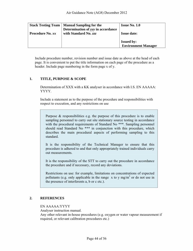
Air Guidance Note (AG8) December 2012
Page 44 of 56
Stack Testing Team Procedure No. xx
Manual Sampling for the Determination of yyy in accordance with Standard No. zzz
Issue No. 1.0 Issue date: Issued by: Environment Manager
Include procedure number, revision number and issue date as above at the head of each page. It is convenient to put the title information on each page of the procedure as a header. Include page numbering in the form page x of y.
1. TITLE, PURPOSE & SCOPE
Determination of XXX with a KK analyser in accordance with I.S. EN AAAAA: YYYY. Include a statement as to the purpose of the procedure and responsibilities with respect to execution, and any restrictions on use
Purpose & responsibilities e.g. the purpose of this procedure is to enable sampling personnel to carry out site stationary source testing in accordance with the procedural requirements of Standard No ***. Sampling personnel should read Standard No *** in conjunction with this procedure, which describes the main procedural aspects of performing sampling to this standard.
It is the responsibility of the Technical Manager to ensure that this procedure is adhered to and that only appropriately trained individuals carry out measurements.
It is the responsibility of the STT to carry out the procedure in accordance the procedure and if necessary, record any deviations.
Restrictions on use: for example, limitations on concentrations of expected pollutants (e.g. only applicable in the range x to y mg/m3 or do not use in the presence of interferents a, b or c etc.).
2. REFERENCES EN AAAAA:YYYY Analyser instruction manual. Any other relevant in-house procedures (e.g. oxygen or water vapour measurement if required, or relevant calibration procedures etc.)
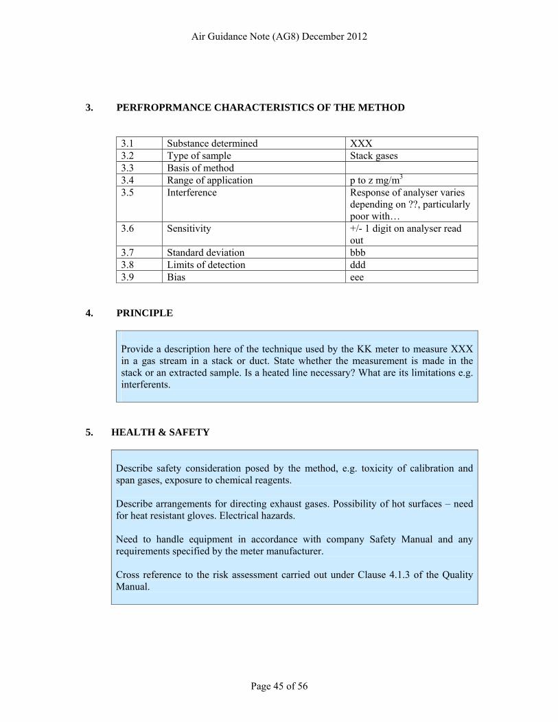
Air Guidance Note (AG8) December 2012
Page 45 of 56
3. PERFROPRMANCE CHARACTERISTICS OF THE METHOD
3.1 Substance determined XXX 3.2 Type of sample Stack gases 3.3 Basis of method 3.4 Range of application p to z mg/m3 3.5 Interference Response of analyser varies
depending on ??, particularly poor with…
3.6 Sensitivity +/- 1 digit on analyser read out
3.7 Standard deviation bbb 3.8 Limits of detection ddd 3.9 Bias eee
4. PRINCIPLE
Provide a description here of the technique used by the KK meter to measure XXX in a gas stream in a stack or duct. State whether the measurement is made in the stack or an extracted sample. Is a heated line necessary? What are its limitations e.g. interferents.
5. HEALTH & SAFETY
Describe safety consideration posed by the method, e.g. toxicity of calibration and span gases, exposure to chemical reagents. Describe arrangements for directing exhaust gases. Possibility of hot surfaces – need for heat resistant gloves. Electrical hazards. Need to handle equipment in accordance with company Safety Manual and any requirements specified by the meter manufacturer. Cross reference to the risk assessment carried out under Clause 4.1.3 of the Quality Manual.
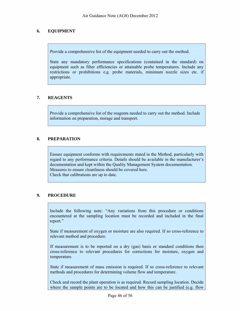
Air Guidance Note (AG8) December 2012
Page 46 of 56
6. EQUIPMENT
Provide a comprehensive list of the equipment needed to carry out the method. State any mandatory performance specifications (contained in the standard) on equipment such as filter efficiencies or attainable probe temperatures. Include any restrictions or prohibitions e.g. probe materials, minimum nozzle sizes etc. if appropriate.
7. REAGENTS
Provide a comprehensive list of the reagents needed to carry out the method. Include information on preparation, storage and transport.
8. PREPARATION
Ensure equipment conforms with requirements stated in the Method, particularly with regard to any performance criteria. Details should be available in the manufacturer’s documentation and kept within the Quality Management System documentation. Measures to ensure cleanliness should be covered here. Check that calibrations are up to date.
9. PROCEDURE
Include the following note: “Any variations from this procedure or conditions encountered at the sampling location must be recorded and included in the final report.”
State if measurement of oxygen or moisture are also required. If so cross-reference to relevant method and procedure.
If measurement is to be reported on a dry (gas) basis or standard conditions then cross-reference to relevant procedures for corrections for moisture, oxygen and temperature.
State if measurement of mass emission is required. If so cross-reference to relevant methods and procedures for determining volume flow and temperature.
Check and record the plant operation is as required. Record sampling location. Decide where the sample points are to be located and how this can be justified (e.g. flow
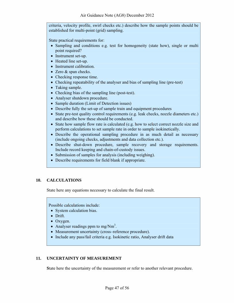
Air Guidance Note (AG8) December 2012
Page 47 of 56
criteria, velocity profile, swirl checks etc.) describe how the sample points should be established for multi-point (grid) sampling.
State practical requirements for: • Sampling and conditions e.g. test for homogeneity (state how), single or multi
point required? • Instrument set-up. • Heated line set-up. • Instrument calibration. • Zero & span checks. • Checking response time. • Checking repeatability of the analyser and bias of sampling line (pre-test) • Taking sample. • Checking bias of the sampling line (post-test). • Analyser shutdown procedure. • Sample duration (Limit of Detection issues) • Describe fully the set-up of sample train and equipment procedures • State pre-test quality control requirements (e.g. leak checks, nozzle diameters etc.)
and describe how these should be conducted. • State how sample flow rate is calculated (e.g. how to select correct nozzle size and
perform calculations to set sample rate in order to sample isokinetically. • Describe the operational sampling procedure in as much detail as necessary
(include ongoing checks, adjustments and data collection etc.). • Describe shut-down procedure, sample recovery and storage requirements.
Include record keeping and chain-of-custody issues. • Submission of samples for analysis (including weighing). • Describe requirements for field blank if appropriate.
10. CALCULATIONS
State here any equations necessary to calculate the final result. Possible calculations include: • System calculation bias. • Drift. • Oxygen. • Analyser readings ppm to mg/Nm3. • Measurement uncertainty (cross–reference procedure). • Include any pass/fail criteria e.g. Isokinetic ratio, Analyser drift data
11. UNCERTAINTY OF MEASUREMENT
State here the uncertainty of the measurement or refer to another relevant procedure.
Air Guidance Note (AG8) December 2012
Page 48 of 56
12. REVIEW DATE
State here the date on which the procedure is scheduled to be subjected to an internal review.
13. APPROVAL ARRANGEMENTS
State here the arrangements for approving the procedure for issue including by whom. If necessary cross-reference another procedure.
END OF MODEL PROCEDURE FOR MEASUREMENT USING A PORTABLE AUTOMATED MEASURING SYSYTEM (AMS) TO A STANDARD METHOD
Air Guidance Note (AG8) December 2012
Page 49 of 56
ANNEX C A MODEL PROCEDURE FOR MANUAL EXTRACTIVE
SAMPLING TO A STANDARD METHOD
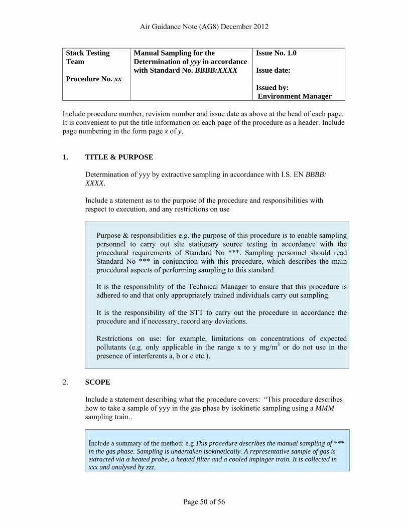
Air Guidance Note (AG8) December 2012
Page 50 of 56
Stack Testing Team Procedure No. xx
Manual Sampling for the Determination of yyy in accordance with Standard No. BBBB:XXXX
Issue No. 1.0 Issue date: Issued by: Environment Manager
Include procedure number, revision number and issue date as above at the head of each page. It is convenient to put the title information on each page of the procedure as a header. Include page numbering in the form page x of y. 1. TITLE & PURPOSE
Determination of yyy by extractive sampling in accordance with I.S. EN BBBB: XXXX. Include a statement as to the purpose of the procedure and responsibilities with respect to execution, and any restrictions on use
Purpose & responsibilities e.g. the purpose of this procedure is to enable sampling personnel to carry out site stationary source testing in accordance with the procedural requirements of Standard No ***. Sampling personnel should read Standard No *** in conjunction with this procedure, which describes the main procedural aspects of performing sampling to this standard.
It is the responsibility of the Technical Manager to ensure that this procedure is adhered to and that only appropriately trained individuals carry out sampling.
It is the responsibility of the STT to carry out the procedure in accordance the procedure and if necessary, record any deviations.
Restrictions on use: for example, limitations on concentrations of expected pollutants (e.g. only applicable in the range x to y mg/m3 or do not use in the presence of interferents a, b or c etc.).
2. SCOPE Include a statement describing what the procedure covers: “This procedure describes
how to take a sample of yyy in the gas phase by isokinetic sampling using a MMM sampling train..
Include a summary of the method: e.g This procedure describes the manual sampling of *** in the gas phase. Sampling is undertaken isokinetically. A representative sample of gas is extracted via a heated probe, a heated filter and a cooled impinger train. It is collected in xxx and analysed by zzz.
Air Guidance Note (AG8) December 2012
Page 51 of 56
3. REFERENCES Standard No. e.g. I.S. EN AAAAA:YYYY + full title Appropriate Manual Sampling Train (MST) Manual. Any other relevant in-house procedures (e.g. oxygen or water vapour measurement if required, or relevant calibration procedures etc.)
Site Review Procedure
4. DEFINITIONS Explain the meanings of any terms and acronyms used in the procedure. 5. RESPONSIBILITIES
State who is responsible for what.
For example:
• State who is responsible for ensuring that the procedure is adhered to and that personnel have had appropriate training and are competent to carry out the sampling in accordance with the procedure.
• State that the STT is responsible for carrying out the sampling in accordance with the procedure, and if necessary record any deviations.
• State who is responsible for calculating results, producing reports and for signing them off.
6. HEALTH & SAFETY
Describe safety consideration posed by the method, e.g. toxicity of calibration and span gases, exposure to chemical reagents. Describe arrangements for directing exhaust gases. Possibility of hot surfaces – need for heat resistant gloves. Electrical hazards. Need to handle equipment in accordance with company Safety Manual and any requirements specified by the meter manufacturer. Cross reference to the risk assessment carried out under Clause 4.1.3 of the Quality Manual.
7. EQUIPMENT & MATERIALS
Provide a comprehensive list of the equipment needed to carry out the method and give brief descriptions, for example: • Entry nozzle. The titanium nozzle is connected to the probe. In order to sample
isokinetically at a wide range of velocities, nozzles of different diameters will be
Air Guidance Note (AG8) December 2012
Page 52 of 56
taken on each sampling campaign. A nozzle diameter of >8mm is recommended and diameters <6mm should be avoided.
• Sample probe. Probe liners are of titanium or quartz with smooth and well-polished internal surface and designed for mechanical cleaning. The heating jacket of the probe has to be capable of maintaining the required temperature (e.g.120 ± 5oC).
• Filter holder. The out-stack filter is supported between two filter pads and housed in a quartz filter holder. The filter holder is placed in a heated box capable of maintaining the required temperature (e.g. 20oC above the flue gas dew point or 120oC whichever is the greater). An in-stack filter arrangement can be used instead of out-stack, with the filter placed between the nozzle and probe. An in-stack filter can only be used if droplets are not present in the flue gas.
• Filters. Quartz filters with proven efficiency of 99.5% on aerosol of 0.3µm diameter (or 99.9% on aerosol of 0.6µm diameter). 110mm of 25mm filter size for out-stack or in-stack respectively. Note: Glass filters cannot be used due to reactions with SO3.
• Impinger Train. A four (4) impinger train. The first two impingers containing the absorbing solution, the third an empty carryover trap with the forth containing silica gel acting as moisture trap.
• MST stack sampler with integrated pump, calibrated dry gas meter, and calibrated flow meter and readouts for stack, probe, filter box and dry gas meter temperatures.
• Probe wash recovery accessories (used to clean the nozzle liner and filter housing or recover particulate phase, if required): HPLC grade or equivalent acetone; glass storage bottles.
• Auxiliary equipment: Port sealing cap; tweezers; PTFE tape; measuring tape (stack/duct diameter); silica gel; barometer; measuring cylinder; industrial marker pen; calculator; stopwatch.
State any mandatory performance specifications (contained in the standard) on equipment such as filter efficiencies or attainable probe temperatures. Include any restrictions or prohibitions e.g. probe materials, minimum nozzle sizes etc. if appropriate.
8. REAGENTS
Provide a comprehensive list of the reagents needed to carry out the method. Include information on preparation, storage, transport and health & safety. For example: • Absorbing Solution (0.1N NaOH): To prepare 1 litre of absorbing solution,
slowly add 4g of NaOH pellets 500ml of distilled/deionised water (σ < 10µS cm-
1). Slowly stir to dissolve. When cool make up to 1litre. Store in a glass or polyethylene bottle.
• Alternatively, commercially prepared NaOH solution may be used. • When high concentrations of acidic gases are expected then 0.2N, 0.5N, 1N or
2N NaOH absorbing solution can be used. • Note: Always wear safety glasses and protective gloves when preparing our
using NaOH solutions.
Air Guidance Note (AG8) December 2012
Page 53 of 56
9. PRE – SAMPLING PROCEDURES
Include instructions and responsibilities, for example: • Ensure equipment conforms with requirements stated in the Method, particularly
with regard to any performance criteria. Details should be available in the manufacturer’s documentation and kept within the Quality Management System documentation.
• Preparatory Work (Sampling Train): Cleaning of glassware. Ensuring absence of particulate material in the nozzle, probe liner and filter housing by rinsing with acetone.
• Loading Equipment: Ensuring that all the equipment needed to complete the sampling exercise is present.
• Calibration of Equipment: Checking that any equipment used to measure emission concentration or equipment used to obtain figures required to standardise concentrations to standard reference conditions is in calibration. Assign responsibility to Team Leader.
• Arrival on site: On arrival at a site the Team Leader will examine the sampling facilities and position to ensure that the sampling team have a safe environment in which to work. If there is any safety issues associated with the existing sampling facilities or lack of sampling facilities these will be resolved before site work commences. Checking continuing validity of risk assessment in accordance with procedure ***.
• Plant status: Ascertain the nature of the plant process (e.g. steady state, cyclic). If the process can perform in a steady state, it is important that it is maintained during sampling.
• Record sampling position: Team Leader to make a sketch of the sampling position in the site logbook. The sketch should include details of the sampling position in relation to: arrestment plant; bends in duct work; fans; dampers; any obstruction that may cause a flow disturbance and the emission point.
• Possible deviations from procedure: If there is any restrictions at the sampling position (e.g. platform size, port orientation, port size) that cause sampling to deviate from the standard, these must be noted in the report.
• Lifting of equipment: If this is required, the sampling team will lift the sampling equipment to the appropriate sampling position using equipment and procedures ***.
• Reference conditions: If oxygen and/or moisture concentrations are required for correction to reference conditions, then state how the analyser should be set up and calibrated in accordance with procedure ***.
10 SAMPLING PROCEDURE
Include the following note: “Any variations from this procedure or conditions encountered at the sampling location must be recorded and included in the final report.”
Air Guidance Note (AG8) December 2012
Page 54 of 56
If measurement is to be reported on a dry (gas) basis or standard conditions then cross-reference to relevant procedures for corrections for moisture, oxygen and temperature. State if measurement of mass emission is required. If so cross-reference to relevant methods and procedures for determining volume flow and temperature. State and describe the practical requirements for: • Sample duration (Limit of Detection issues) • Sample train set-up and equipment operations • Pre-test quality control requirements (e.g. leak checks, nozzle diameters etc.)
and how these should be conducted. • Calculation of sample flow rate (e.g. how to select correct nozzle size and
perform calculations to set sample rate in order to sample isokinetically. • The operational sampling procedure in as much detail as necessary (include
ongoing checks, adjustments and data collection etc.) Describe shut-down procedure, sample recovery and storage requirements. Include record keeping and chain-of-custody issues.
• Submission of samples for analysis (including weighing) • Requirements for field blank. • Requirements for isokinetic sampling, and selection of appropriate nozzle
size and k-factor, calculated in accordance with procedure ***. • Preliminary calculation of the minimum sample volume required to verify that
the detection limit attainable is ≤10% of the emission limit value. • Sampling emissions from at least one complete cycle of a cyclic process. • Leak checking the Pitot tubes. • Measuring the stack/duct diameter and marking a relevant sized sample
probe (together with a thermocouple and Pitot tube) to take Pitot pressure and temperature readings at across each sampling traverse.
• Determining at each traverse point whether the flow direction meets the flow angle criteria of <15o .in accordance with procedure ***,.
• Checking the results from the initial traverse against requirements specified in the method to ensure compliance
• Visual checking of the nozzle and actions to be taken if there are any visible defects (e.g. placing in quarantine).
• Calculation of the isokinetic sampling rate. • Setting up the sampling and impinger train. • Modification of sampling and impinger train where high concentrations of
acidic gases are expected. • Leak-checks. • Sampling. (Any significant process variation during sampling should be
noted. Sampling must be stopped if the required sampling rate cannot be
maintained, or if the plant operation is interrupted.) • Shut-down. (This should include a post sampling leak check. • Recovery of particulate material. • Weight measurements (e.g. weight gain of each impinger for the purpose of
calculating flue gas moisture.) • Analytical requirements
• (e.g storage in dark glass jars • storage at a temperature not exceeding 4ºC (how could this be
demonstrated?)
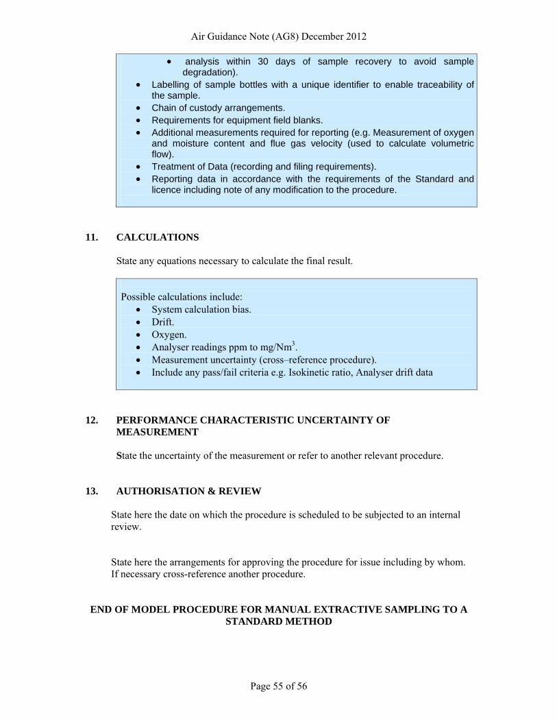
Air Guidance Note (AG8) December 2012
Page 55 of 56
• analysis within 30 days of sample recovery to avoid sample degradation).
• Labelling of sample bottles with a unique identifier to enable traceability of the sample.
• Chain of custody arrangements. • Requirements for equipment field blanks. • Additional measurements required for reporting (e.g. Measurement of oxygen
and moisture content and flue gas velocity (used to calculate volumetric flow).
• Treatment of Data (recording and filing requirements). • Reporting data in accordance with the requirements of the Standard and
licence including note of any modification to the procedure.
11. CALCULATIONS State any equations necessary to calculate the final result. Possible calculations include:
• System calculation bias. • Drift. • Oxygen. • Analyser readings ppm to mg/Nm3. • Measurement uncertainty (cross–reference procedure). • Include any pass/fail criteria e.g. Isokinetic ratio, Analyser drift data
12. PERFORMANCE CHARACTERISTIC UNCERTAINTY OF
MEASUREMENT State the uncertainty of the measurement or refer to another relevant procedure.
13. AUTHORISATION & REVIEW
State here the date on which the procedure is scheduled to be subjected to an internal review.
State here the arrangements for approving the procedure for issue including by whom. If necessary cross-reference another procedure.
END OF MODEL PROCEDURE FOR MANUAL EXTRACTIVE SAMPLING TO A STANDARD METHOD
Air Guidance Note (AG8) December 2012
Page 56 of 56
References
[1] Policy on Monitoring of Stack Emissions to Air at EPA Licensed Sites. EPA, March 2012. http://www.epa.ie/downloads/advice/air/emissions
[2] I.S. EN ISO/IEC 17025:2005 General requirements for the competence of testing and calibration
laboratories. [3] I.S. EN ISO 9001:2000 Quality management system - Requirements [4] I.S. EN ISO14001:2004 Environmental management systems. Requirements with guidance for use [5] I.S. CEN/TS 15675:2007 Air Quality – Measurement of stationary source emissions – Application
of EN ISO/IEC 17025:2005 to periodic measurements [6] I.S. EN 15259:2007 Air quality – Measurement of stationary source emissions – Requirement for
measurement sections and sites and for the measurement objective, plan and report. [7] Guidance Note on Site Safety Requirements for Air Emissions Monitoring (AG1). Rev.3, April
2010, Environmental Protection Agency, Office of Environmental Enforcement (OEE). http://www.epa.ie/downloads/advice/air/emissions/ [8] Air Emissions Monitoring Guidance Note (AG2). Environmental Protection Agency, Office of
Environmental Enforcement (OEE). http://www.epa.ie/downloads/advice/air/emissions [9] Technical Guidance Note M1, Sampling requirements for monitoring stack emissions to air.
Version 6, January 2010.Environment Agency, UK www.mcerts.net [10] Technical Guidance Note M2, Monitoring stack emissions to air. Version Draft 2012.Environment
Agency, UK www.mcerts.net [11] Manual stack emission monitoring. Performance standard for organisations. Version 7.2,
November 2011, Environment Agency, UK www.mcerts.net [12] Personnel competency standard for manual stack-emission monitoring. Version 8. April 2012,
Environment Agency, UK www.mcerts.net
[13] Method Implementation Documents. Environment Agency, UK
www.mcerts.net [14] I.S. EN ISO 14956 Evaluation of the suitability of a measurement method by comparison with a
stated measurement uncertainty [15] Agency requirements for applying measurement uncertainty (MU) to periodic air monitoring http://www.epa.ie/downloads/advice/air/emissions