Embed Size (px)
Citation preview

AFQTP 3E1X1-27 13 DECEMBER 02
AIR FORCE QUALIFICATION TRAINING PACKAGE (AFQTP)
FOR
HEATING, VENTILATION, AIR CONDITIONING/REFRIGERATION (HVAC/R)
(3E1X1)
MODULE 27
AFSC SPECIFIC CONTINGENCY RESPONSIBILITIES

AFQTP 3E1X1-27
TABLE OF CONTENTS
MODULE 27
AFSC SPECIFIC CONTINGENCY RESPONSIBILITIES
AFQTP GUIDANCE INTRODUCTION..............................................................................................27-4
AFQTP UNIT 2 TENT HEATER: PREWAY
PERFORM OPERATIONAL TESTS (27.2.1.3.3.) ............................................27-5 150 CUBIC FT REFRIGERATION UNIT
CONDUCT PRE-OPERATIONAL TEST (27.2.2.2.2.) ......................................27-9 SERVICE/PERIODIC MAINTENANCE (27.2.2.2.3.) ........................................27-9
TROUBLESHOOT USING ELECTRICAL SCHEMATIC (27.2.2.2.4.1.) .........................................27-9 MECHANICAL MALFUNCTIONS (27.2.2.2.4.2.) .............................................27-9
BARE BASE AIR CONDITIONER UNIT (A/E 32C-39) PERFORM OPERATIONAL TESTS (27.2.2.4.2.) ..........................................27-22 SERVICE/PERIODIC MAINTENANCE (27.2.2.4.3) .......................................27-22
TROUBLESHOOT USING ELECTRICAL SCHEMATIC (27.2.2.4.4.1) ........................................27-22 MECHANICAL MALFUNCTIONS (27.2.2.4.4.2.) ...........................................27-22
FIELD DEPLOYABLE ENVIRONMENTAL CONTROL UNIT (FDECU) PERFORM OPERATIONAL TESTS (27.2.2.5.2.) ..........................................27-32 SERVICE/PERIODIC MAINTENANCE (27.2.2.5.3) .......................................27-32
TROUBLESHOOT USING ELECTRICAL SCHEMATIC (27.2.2.5.4.1) ........................................27-32 MECHANICAL MALFUNCTIONS (27.2.2.5.4.2.) ...........................................27-32
SMALL SHELTER SYSTEM ENVIRONMENTAL CONTROL UNIT (SSS ECU) PERFORM OPERATIONAL TESTS (OPTIONAL).........................................27-41 SERVICE/PERIODIC MAINTENANCE (OPTIONAL) ....................................27-41
TROUBLESHOOT USING ELECTRICAL SCHEMATIC (OPTIONAL) .........................................27-41 MECHANICAL MALFUNCTIONS (OPTIONAL).............................................27-41
AFQTP UNIT 3 FIELD BOILERS (M-80)
PERFORM OPERATIONAL TESTS (27.3.2.3.) .............................................27-50 SERVICE/PERIODIC MAINTENANCE (27.3.2.4.) .........................................27-50
TROUBLESHOOT USING ELECTRICAL SCHEMATIC (27.3.2.5.1.) ..........................................27-50 MECHANICAL MALFUNCTIONS (27.3.2.5.2.) ..............................................27-50
Notice. This AFQTP is NOT intended to replace the applicable technical references nor is it intended to replace hands-on training. It is to be used in conjunction with these for training purposes only.
27-2

AFQTP 3E1X1-27
TABLE OF CONTENTS (CONTINUED)
REVIEW ANSWER KEY.......................................................................................................KEY-1
CORRECTIONS/IMPROVEMENT LETTER ............................................................. APPENDIX A
Career Field Education and Training Plan (CFETP) references from 1 July 2002 version.
OPR: HQ AFCESA/CEOF Certified by: HQ AFCESA/CEOF (SMSgt Dan Sacks) (CMSgt Myrl F. Kibbe) Supersedes AFQTP 3E1X1-27, 30 Jun 00 Pages: 61/Distribution F
Notice. This AFQTP is NOT intended to replace the applicable technical references nor is it intended to replace hands-on training. It is to be used in conjunction with these for training purposes only.
27-3

AFQTP 3E1X1-27
AIR FORCE QUALIFICATION TRAINING PACKAGES
FOR HEATING, VENTILATION, AIR CONDITIONING/REFRIGERATION
(HVAC/R)
(3E1X1)
INTRODUCTION
Before starting this AFQTP, refer to and read the “AFQTP Trainer/Trainee Guide.” AFQTPs are mandatory and must be completed to fulfill task knowledge requirements on core and diamond tasks for upgrade training. It is important for the trainer and trainee to understand that an AFQTP does not replace hands-on training, nor will completion of an AFQTP meet the requirement for core task certification. AFQTPs will be used in conjunction with applicable technical references and hands-on training. AFQTPs and Certification and Testing (CerTest) must be used as minimum upgrade requirements for Diamond tasks.
MANDATORY minimum upgrade requirements:
Core task: AFQTP completion Hands-on certification Diamond task: AFQTP completion CerTest completion (80% minimum to pass) Note: Trainees will receive hands-on certification training for Diamond Tasks when equipment becomes available either at home station or at a TDY location. Put this package to use. Subject matter experts, under the direction and guidance of HQ AFCESA/CEOF, revised this AFQTP. If you have any recommendations for improving this document, please contact the HVAC/R Career Field Manager at the address below.
HQ AFCESA/CEOF 139 Barnes Dr. Suite 1
Tyndall AFB, FL 32403-5319 DSN: 523-6445, Comm: (850) 283-6445
Fax: DSN 523-6488 Or E-mail: [email protected]
Notice. This AFQTP is NOT intended to replace the applicable technical references nor is it intended to replace hands-on training. It is to be used in conjunction with these for training purposes only.
27-4

AFQTP 3E1X1-27 27.2.1.3.3.
EXPEDIENT BEDDOWN METHODS
TENT HEATER
PREWAY
MODULE 27 AFQTP UNIT 2
PERFORM OPERATIONAL TESTS (27.2.1.3.3.)
Notice. This AFQTP is NOT intended to replace the applicable technical references nor is it intended to replace hands-on training. It is to be used in conjunction with these for training purposes only.
27-5

AFQTP 3E1X1-27 27.2.1.3.3.
PERFORM OPERATIONAL TESTS
Task Training Guide
STS Reference Number/Title:
27.2.1.3.3. - Perform operational tests on Preway tent heater.
Training References:
1. TM 5-4520-235-13, Operator, Organizational and Direct Support Maintenance Manual, Heater, Space, Preway Inc. Models 444-3A, 444-3ABJ, 444-2-ABEX, 444-4-ABJ, 444-4A, 441-4ABJ, and Montag Model SH-70B.
2. Career Development Course (CDC) HVAC/R Journeyman 3E151F, Volume 4, Unit 1, Section 1-3; Lesson 610: Setup Procedures for Preway Heaters, Lesson 611: Operation and Maintenance Procedures of a Preway Tent Heater, and Lesson 612: Troubleshooting and Regulating a Preway Tent Heater.
3. Video PIN # 613247, Part # V, Preway Space Heater. 4. CD-ROM, Air Force Qualification Training Package (AFQTP)
3E1X1, HVAC/R, Version 1.0, Aug 99: Preway Space Heater.
Prerequisites: 1. Possess a minimum of a 3E131 AFSC. 2. Review the following references:
2.1. TM 5-4520-235-13. 2.2. CDC HVAC/R Journeyman 3E151F, Volume 4, Unit 1, Section 1-3, Lessons 610, 611, and 612.
3. Complete CD-ROM, AFQTP 3E1X1, HVAC/R, Version 1.0, Aug 99: Preway Space Heater.
Equipment/Tools Required:
1. Leather gloves. 2. Fire extinguisher. 3. Adjustable wrench 8” (2 ea.). 4. Ignition source. (Note: Tissue paper only if wick is not available.)
Learning Objective:
The trainee should know the steps required to safely perform operational tests on Preway Tent Heaters.
Samples of Behavior:
Trainee will safely perform operational tests on a Preway Tent Heater.
Notes: Any safety violation is an automatic failure.
Notice. This AFQTP is NOT intended to replace the applicable technical references nor is it intended to replace hands-on training. It is to be used in conjunction with these for training purposes only.
27-6

AFQTP 3E1X1-27 27.2.1.3.3.
PERFORM OPERATIONAL TESTS
1. Background. On a contingency, one of your tasks will be to set up space heaters for the tents. The preway heaters are fuel oil burning, non-electric, high radiant type heaters having an output capacity of 50,000 to 70,000 British Thermal Units (BTU) per hour. The basic heater is shipped completely assembled and ready for installation. This unit will explain how to perform operational tests on a preway heater. 2. Complete the CD-ROM AFQTP 3E1X2 HVAC/R, Version 1.0, Aug 99: Preway Space Heater. Upon completion of the above-mentioned CD-ROM properly perform operational tests using the step-by-step procedures listed below.
NOTE: The review questions for this material are in the above-mentioned CD-ROM.
3. Procedures. Follow these steps To perform operational tests on a preway heater:
SAFETY: ENSURE THAT FIRE EXTINGUISHER IS OPERABLE AND ALWAYS AT HAND.
Step 1: Locate TM 5-4520-235-13. Step 2: Assemble heater components in accordance with (IAW) TM 5-4520-235-13, Chapter 2, Section 1, Paragraph 2-2. Step 3: Install/Set-up heater IAW TM 5-4520-235-13, Chapter 2, Section 1, Paragraph 2-3, and Figure 2-2. Step 4: Check control valve IAW TM 5-4520-235-13, Chapter 2, Section 1, Paragraph 2-4.
SAFETY: ALWAYS KEEP SAFETY PROCEDURES IN MIND WHEN DEALING WITH FIRE OR FIRE PRODUCING EQUIPMENT. KEEP YOUR FACE AND HANDS AWAY FROM THE OPENING.
Step 5: Start the heater IAW TM 5-4520-235-13, Chapter 2, Section 1, Paragraph 2-5. Step 6: Stop the heater IAW TM 5-4520-235-13, Chapter 2, Section 1, Paragraph 2-6.
Notice. This AFQTP is NOT intended to replace the applicable technical references nor is it intended to replace hands-on training. It is to be used in conjunction with these for training purposes only.
27-7

AFQTP 3E1X1-27 27.2.1.3.3.
PERFORM OPERATIONAL TESTS PERFORMANCE CHECKLIST INSTRUCTIONS:
The trainee must satisfactorily perform all parts of the task without assistance. Evaluate the trainee’s performance using this checklist.
DID THE TRAINEE…. YES NO Assembly/Install/Set-up 1. assemble heater correctly? 2. select an area/room with adequately ventilated to insure complete
combustion of fuel oil?
3. select an location for the heater installation at least three feet from combustible material? (If noncombustible shielding is used, six inches is required spacing from heater.)
4. place heater on a noncombustible board of sufficient size as to extend beyond the rear and sides of the fuel oil can?
5. level the heater and oil control valve correctly? 6. install the heater pipe elbow onto the heater flue collar correctly? 7. install smokestack, draft regulator, and rain cap correctly? (Smokestack a
minimum of 18 inches above highest point of tent/roof.)
Starting the Heater 8. check the combustion chamber for any trash or foreign objects? 9. install siphon assembly in the fuel can correctly?
10. prime the heater correctly? 11. check fuel line and connections for leaks? 12. ensure the fire extinguisher is operable and within the operating perimeter
before starting the heater?
13. successfully start the heater? (Waited 15 minute before making any flame adjustment.)
14. wait the appropriate time after make a flame adjustment? (Ten minutes.) Stopping the Heater
15. shut down heater correctly? 16. allow the heater to cool 30 minutes before relighting, if needed? 17. comply with all safety requirements? FEEDBACK: Trainer/Certifier should provide both positive and/or negative feedback to the trainee immediately after the task is performed. This will ensure the issue is still fresh in the mind of both the trainee and trainer/certifier.
Notice. This AFQTP is NOT intended to replace the applicable technical references nor is it intended to replace hands-on training. It is to be used in conjunction with these for training purposes only.
27-8
AFQTP 3E1X1-27 27.2.2.2.2. 27.2.2.2.3.
27.2.2.2.4.1. 27.2.2.2.4.2.
EXPEDIENT BEDDOWN METHODS
150 CUBIC FOOT REFRIGERATION UNIT
MODULE 27 AFQTP UNIT 2
CONDUCT PRE-OPERATIONAL TEST (27.2.2.2.2.) SERVICE/PERIODIC MAINTENANCE (27.2.2.2.3.)
TROUBLESHOOT: USING ELECTRICAL SCHEMATIC (27.2.2.2.4.1.) MECHANICAL MALFUNCTIONS (27.2.2.2.4.2.)
Notice. This AFQTP is NOT intended to replace the applicable technical references nor is it intended to replace hands-on training. It is to be used in conjunction with these for training purposes only.
27-9

AFQTP 3E1X1-27 27.2.2.2.2. 27.2.2.2.3.
27.2.2.2.4.1. 27.2.2.2.4.2.
(150 CUBIC FOOT REFRIGERATION UNIT)
CONDUCT PRE-OPERATIONAL TESTS SERVICE/PERIODIC MAINTENANCE
TROUBLESHOOT USING ELECTRICAL SCHEMATIC TROUBLESHOOT MECHANICAL MALFUNCTIONS
Task Training Guide
STS Reference Number/Title:
27.2.2.2.2. - Conduct pre-operational tests on a 150 cubic foot refrigeration unit. 27.2.2.2.3. - Perform service/periodic maintenance on a 150 cubic foot refrigeration unit. 27.2.2.2.4.1. - Troubleshoot using electrical schematic on 150 cubic foot refrigeration unit. 27.2.2.2.4.2. - Troubleshoot mechanical malfunctions on 150 cubic foot refrigeration unit.
Training References:
1. Technical Order (TO) 40R7-5-8-1, Operator and Organizational Direct Support Maintenance Manual, Refrigeration Unit, Mechanical: Panel Type, 5,000 BTU/Hr, Electric Motor Driven, ERU-5E.
2. Technical Manuals (TM) 9-4110-254-14, Operator and Organizational Direct Support Maintenance Manual, Refrigeration Unit, Mechanical, 5K BTU, Electric Model F5000RE.
3. TM 5-4110-240-13&P, Operator's Organizational and Direct Support Maintenance Manual With Repair Parts and Special Tools List, Refrigerator, Mechanical, Field, Portable, Walk-In, Plug-In (150 Cubic Foot), MDSI-150R.
4. Video PIN # 613245, Bare Base Mechanical Systems, Part # lll -Walk-In Refrigeration Units.
5. CD-ROM Air Force Qualification Training Package (AFQTP) 3E1X1, HVAC/R, Version 1.0, Jan 98: 150 Cubic Foot Refrigerator.
6. Career Development Course (CDC) HVAC/R Journeyman 3E151F, Volume 4, Unit 2, Section 2-2, Lessons 615: Characteristic and Operation of the 150 Cubic Foot Refrigeration Unit and 616: 150 Cubic Foot Refrigeration Maintenance, Troubleshooting, and Repair.
7. CDC HVAC/R Journeyman 3E151D, Volume 3, Unit 2: Electrical Diagrams, Meters, and Troubleshooting.
Notice. This AFQTP is NOT intended to replace the applicable technical references nor is it intended to replace hands-on training. It is to be used in conjunction with these for training purposes only.
27-10

AFQTP 3E1X1-27 27.2.2.2.2. 27.2.2.2.3.
27.2.2.2.4.1. 27.2.2.2.4.2.
(150 CUBIC FOOT REFRIGERATION UNIT)
Task Training Guide (CONTINUED) Prerequisites: 1. Possess a minimum of a 3E131 AFSC.
2. Review the following references: 2.1. TO 40R7-5-8-1, TMs, 9-4110-254-14, and 5-4110-240-13&P. 2.2. CDC HVAC/R Journeyman 3E151F, Volume 4, Unit 2, Section 2-2, Lessons 615 and 616. 2.3. CDC HVAC/R Journeyman 3E151D, Volume 3, Unit 2.
3. Complete CD-ROM AFQTP 3E1X1, HVAC/R, Version 1.0, Jan 98: 150 Cubic Foot Refrigerator.
Equipment/Tools Required:
1. Personnel protective equipment (PPE). 2. HVAC/R tool bag. 3. 150 Cubic Foot Refrigerator with mechanical unit.
Learning Objective:
Trainee should know the steps required to safely perform: 1. A pre-operational test on a 150 cubic foot refrigerator
mechanical unit. 2. Service/periodic maintenance on a 150 cubic foot refrigerator
mechanical unit. 3. Troubleshooting using electrical schematic. 4. Troubleshooting mechanical malfunctions.
Samples of Behavior:
Trainee will perform: 1. The required inspection on the items on a pre-operational test. 2. Service/periodic maintenance on a 150 cubic foot mechanical
unit. 3. Troubleshooting using electrical schematic on a 150 cubic foot
mechanical unit. 4. Troubleshooting mechanical malfunctions on a 150 cubic foot
mechanical unit.
Notes: 1. Any safety violation is an automatic failure. 2. Trainer must develop training scenarios to complete troubleshooting tasks.
Notice. This AFQTP is NOT intended to replace the applicable technical references nor is it intended to replace hands-on training. It is to be used in conjunction with these for training purposes only.
27-11

AFQTP 3E1X1-27 27.2.2.2.2. 27.2.2.2.3.
27.2.2.2.4.1. 27.2.2.2.4.2.
(150 CUBIC FOOT REFRIGERATION UNIT)
CONDUCT PRE-OPERATIONAL TESTS SERVICE/PERIODIC MAINTENANCE
TROUBLESHOOT USING ELECTRICAL SCHEMATIC TROUBLESHOOT MECHANICAL MALFUNCTIONS
1. Background. In the initial stages of a deployment, the troops may have to subsist on MRE's. However, if you were on that deployment, you would probably want that initial stage to be as short as possible. One of the first requirements in setting up a field kitchen is to have refrigerators to keep foods fresh. The primary piece of equipment used by the Air Force for this purpose is the one hundred fifty cubic foot refrigerator. Remember that there are two different models of mechanical units on these boxes out in the field. The older model using R-12 and the newer model using R-134a. As an HVAC technician, you should be able to maintain both of them. 2. Unit Comparison. Both the R12 and R134a mechanical units perform the same tasks and mount exactly the same on the 150 cubic foot refer box. They both have the same electrical requirements. However, there are some differences between the two other than the different refrigerants.
2.1. The R12 unit has an open type compressor whereas the R134a has a semi-hermetic. 2.2. The R12 has a single-phase fan motor and the R134a’s is three-phase (therefore, rotation must be checked). 2.3. The R12 does not have safety switches on the side panels. 2.4. The R12 has a mechanical defrost timer and the R134a’s is electronic. 2.5. Small fuses protect the control circuit on the R134a and the fuses on the R12 unit protect the entire unit. 2.6. The R134a unit has forklift openings and the R12 does not. 2.7. The compressor suction and discharge access valves on the 134a unit do not require to be “gauged”. 2.8. The R134a System “pumps down” whenever the toggle switch is turned off or the unit cycles off on the thermostat and the R12 does not.
3. Complete the CD-ROM AFQTP 3E1X1 HVAC/R, Version 1.0, Jan 98: 150 Cubic Foot Refrigerator for detailed instructions on operational tests, service/periodic maintenance, and troubleshooting of the 150 cubic foot refrigerator and R12 mechanical unit. After completing the CD-ROM AFQTP and reviewing the following information see your Unit Education and Training Manager (UETM) to take the following mandatory CerTest tests:
CerTest # CerTest Title 8065 150 Cubic Foot Refrigerator QTP - Lesson 1 8066 150 Cubic Foot Refrigerator QTP - Lesson 2 8067 150 Cubic Foot Refrigerator QTP - Lesson 3 8068 150 Cubic Foot Refrigerator QTP - Lesson 4 8069 150 Cubic Foot Refrigerator QTP - Lesson 5
Trainee must score at least 80% to meet the minimum completion requirement for diamond tasks.
Notice. This AFQTP is NOT intended to replace the applicable technical references nor is it intended to replace hands-on training. It is to be used in conjunction with these for training purposes only.
27-12

AFQTP 3E1X1-27 27.2.2.2.2. 27.2.2.2.3.
27.2.2.2.4.1. 27.2.2.2.4.2.
NOTE: 1. The review questions for the R-12 unit are in the above-mentioned CD-ROM. The review
question for the 134a unit is located in this document.
2. To increase the chances of obtaining a passing score, recommend you take each corresponding CerTest after you complete a lesson. Contact your UETM to schedule testing.
IF EQUIPMENT IS AVAILABLE, PERFORM THE FOLLOWING FOR HANDS-ON CERTIFICATION TRAINING.
4. R-12 Pre-operational Procedures. Follow this step to conduct pre-operational tests on a R-12 Mechanical Unit:
CAUTION: FAILURE TO FOLLOW PRE-OPERATIONAL CHECKS CAN RESULT IN MAJOR DAMAGE TO THE UNIT.
Step 1: Locate TO 40R7-5-8-1/TM 5-4110-239-14 and conduct pre-operational tests in accordance with (IAW) TO 40R7-5-8-1/TM 5-4110-239-14, Chapter 4, Section II, Paragraph 4-8 and 4-9.
5. R134a Pre-operational Procedures. Follow this step to conduct per-operational tests on a R134a Mechanical Unit:
Step 1: Locate TM 9-4110-254-14 and conduct pre-operational tests IAW TM 9-4110-254-14, Chapter 4, Section II, Paragraph 4-6 and 4-7.
6. R-12 Maintenance Procedures. Follow this step to perform service/periodic maintenance on a R-12 Mechanical Unit:
Step 1: Locate TO 40R7-5-8-1/TM 5-4110-239-14 and perform service/periodic maintenance IAW TO 40R7-5-8-1, Chapter 2, Section II, Paragraph 2-3 and Table 2-1..
7. R134a Maintenance Procedures. Follow this step to perform service/periodic maintenance on a R134a Mechanical Units:
Step 1: Locate TM 9-4110-254-14 and perform service/periodic maintenance IAW TM 9-4110-254-14, Chapter 2, Section III, Paragraph 4-9, 4-10, and Table 4-1..
Notice. This AFQTP is NOT intended to replace the applicable technical references nor is it intended to replace hands-on training. It is to be used in conjunction with these for training purposes only.
27-13

AFQTP 3E1X1-27 27.2.2.2.2. 27.2.2.2.3.
27.2.2.2.4.1. 27.2.2.2.4.2.
8. Troubleshooting. Since troubleshooting is a step-by-step procedure, the effectiveness depends on how much you know about the equipment and how much you think while working. The ability to troubleshoot depends on your capability to think and apply knowledge. To troubleshoot effectively, you must follow a systematic procedure. First, study the symptoms of the trouble thoroughly and ask yourself these questions:
8.1. What were the warning signs preceding the trouble? 8.2. What recent repair has been done? 8.3. Has a similar trouble occurred before? 8.4. Next, follow the basic troubleshooting procedures:
8.4.1. The first step is to perform an operational check to determine if an actual problem really exists. Follow step-by-step procedures in the technical manual for your particular item of equipment (also explained above). Perform a visual inspection of the electrical components, check wiring harness for breaks, and check relays for loose connections, evidence of over heating, cracks, or any signs of damage.
8.4.2. The second step in troubleshooting is to analyze the malfunction. Detect the trouble by sight, sound, smell, or feel. Once you are aware of a malfunction, consult the proper technical manual for normal operation. This gives one a clearer understanding of how things should be working. One can also use the troubleshooting chart located in the proper technical manual. It is in this step that one determines the type of trouble in order to determine the type of test equipment to use.
8.4.3. The third step is locating the malfunction; this is the most difficult task. In this step, one will need to stay focused on the problem and not allow frustration to set in. This can cause one to resort back to the remove and replace technique. Perform the previous steps; determine type of test equipment needed to check the performance. Understanding the operation and knowing the “how, what, when and where” is the key to locating the malfunction.
8.4.4. The fourth step is to perform corrective action, once you have located the problem; a neat and permanent repair is a necessity. If possible, use original replacement parts to make repairs.
8.4.5. The last step is to perform an operational check; this is the most rewarding step in the troubleshooting process. If you do not prove your work, you will not know if the problem is solved. Remember, one malfunction can produce more than one problem.
8.5. Troubleshooting Electrical Circuits. As previously mentioned, you must follow a systematic process to correct malfunctions on a piece of equipment. In order to correct an electrical problem, you must apply your electrical knowledge that you have learned from prior tasks. To name a few you must be able to read and interpret wiring diagrams, electrical circuit components and types, the different types of fuses, circuit breakers, and switches. Most of all you must have a thorough working knowledge of the different types of meters that can be used to help you test electrical circuits for troubles such as an open circuit, a shorted circuit, or a grounded circuit. These areas are covered in detail in the CDCs, if you need to brush up on the different electrical symbols, types of electrical circuits, and meters that youcan use in troubleshooting, refer to 3E351F, Volume 1, Unit 2.
Notice. This AFQTP is NOT intended to replace the applicable technical references nor is it intended to replace hands-on training. It is to be used in conjunction with these for training purposes only.
27-14

AFQTP 3E1X1-27 27.2.2.2.2. 27.2.2.2.3.
27.2.2.2.4.1. 27.2.2.2.4.2.
NOTE: Since the AFQTP CD-ROM does not cover the electrical portion of the R134a mechanical system we put together the sequence of events (Table 2-1) that must happen in order for a 134a mechanical unit to operate. As we explain the sequence of events that must occur in order for the unit to operate, refer to the wiring diagram (Figure 2-1) located on page 27-15.
SAFETY: MANY TIMES TROUBLESHOOTING MUST BE ACCOMPLISHED WITH THE POWER ON. USE EXTREME CAUTION AND MAKE SURE TRAINEE HAS REMOVED ALL JEWELRY.
Table 2-1. Electrical Sequence of Events for R134a Mechanical Unit.
Sequence of Events After the power and the breaker is on, the control circuit is powered through two fuses (f1 & f2) from B phase and C phase. (Note: the control circuit remains energized on the right side by C phase). From F1, B phase passes through two contact switches located in the door and wired in series. That same circuit then ties to S1-2, K3-7, K4-7, and K4-9. When the toggle switch is turned on and the thermostat is closed, K3 is energized which in turn closes the contacts on K3. At the same time L1 (liquid line solenoid valve) is energized. With the solenoid now open, the suction pressure begins to rise and the combination pressure control (S2) closes sending power through S5 (oil pressure switch) and motor starter overload (KI-OL) and on to energize K1 which energizes the compressor. At the same time K4 is energized closing contacts 7/4 and 9/6 which in turn sends power to K2 which energizes the fan. If the differential oil pressure fails to rise within 120 seconds then contact S5 will open shutting down the compressor. The defrost timer accumulates time as long as the defrost temperature switch (S4) is closed. (Note: The defrost timer is electronic and no repairs can be made to it in the field). The timer calls for defrost by switching contacts TM1 9 & 3 to 9 & 6 and 7&1 to 7&4. The compressor remains on but power is lost at K2 turning off the fan. The defrost solenoid (L2) is energized and the hot gas defrost valve opens for defrost. Defrost continues until the timer switches back or the defrost termination control opens. In either case the unit will switch back to the cooling mode.
Notice. This AFQTP is NOT intended to replace the applicable technical references nor is it intended to replace hands-on training. It is to be used in conjunction with these for training purposes only.
27-15

AFQTP 3E1X1-27 27.2.2.2.2. 27.2.2.2.3.
27.2.2.2.4.1. 27.2.2.2.4.2.
Figure 2-1. Electrical Schematic 134a.
Notice. This AFQTP is NOT intended to replace the applicable technical references nor is it intended to replace hands-on training. It is to be used in conjunction with these for training purposes only.
27-16

AFQTP 3E1X1-27 27.2.2.2.2. 27.2.2.2.3.
27.2.2.2.4.1. 27.2.2.2.4.2.
8.6. Troubleshooting Mechanical Malfunctions. As with electrical malfunctions, you must follow a systematic process to correct mechanical malfunctions on a piece of equipment. You will find that the possible mechanical problems that are associated with refrigeration systems can be of numerous and varied types. The following are some typical problems that you may encounter on any refrigeration system. The CDC covers these areas very well. If you need to brush up on the technique used in solving these problems, refer to 3E151F, Volume 2, Unit 2: Troubleshooting Refrigeration Systems.
8.6.1. Low refrigerant charge. 8.6.2. Excess refrigerant charge. 8.6.3. Inefficient evaporator. 8.6.4. Inefficient condenser. 8.6.5. Restriction in the refrigerant circuit. 8.6.6. Inefficient compressor.
NOTE TO TRAINER/CERTIFIER: In order for the trainee to complete the following tasks, you must provide the equipment and training scenarios for electrical and mechanical troubleshooting. You can use the troubleshooting section in TM 9-4110-254-14, Chapter 4, Section IV, Paragraph 4-12 to help ydevelop the troubleshooting
ou scenarios.
9. Electrical Troubleshooting Procedures. Follow these steps to perform electrical troubleshooting using schematics:
Step 1: Trainee is provided equipment and electrical malfunction problem scenario in which to perform task. Step 2: Use five step process in troubleshooting:
2.1. Perform an operational check. 2.2. Analyze the malfunction. 2.3. Locate the malfunction. 2.4. Perform corrective action. 2.5. Perform an operational check.
Step 3: Document maintenances/repairs performed. 10. Mechanical Troubleshooting Procedures. Follow these steps to perform troubleshooting of a mechanical malfunction:
Step 1: Trainee is provided equipment and mechanical malfunction problem scenario in which to perform task.
Notice. This AFQTP is NOT intended to replace the applicable technical references nor is it intended to replace hands-on training. It is to be used in conjunction with these for training purposes only.
27-17

AFQTP 3E1X1-27 27.2.2.2.2. 27.2.2.2.3.
27.2.2.2.4.1. 27.2.2.2.4.2.
Step 2: Use five-step process in troubleshooting:
2.1. Perform an operational check. 2.2. Analyze the malfunction. 2.3. Locate the malfunction. 2.4. Perform corrective action. 2.5. Perform an operational check.
Step 3: Document maintenances/repairs performed.
Notice. This AFQTP is NOT intended to replace the applicable technical references nor is it intended to replace hands-on training. It is to be used in conjunction with these for training purposes only.
27-18
AFQTP 3E1X1-27 27.2.2.2.2. 27.2.2.2.3.
27.2.2.2.4.1. 27.2.2.2.4.2.
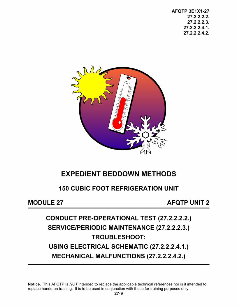
REVIEW QUESTIONS FOR
134a MECHANICAL UNIT
QUESTION ANSWER 1. How many valves must be opened for
normal operation? e. 2. f. 3. g. 4. h. 5. i. 6.
2. What valve left closed would cause the unit
to be off on low pressure?
a. Compressor discharge valve. b. Hot gas hand valve. c. Liquid line hand valve. d. Oil pressure regulating valve.
3. It is normal for the fan to shut off in the defrost mode.
a. True. b. False.
4. What is the time limit on the delay of the differential oil pressure switch?
a. 30 seconds. b. 60 seconds. c. 90 seconds. d. 120 seconds.
5. The defrost timer can be repaired in the field.
a. True. b. False.
Referring to Figure 1 on page 27-15, answer the following questions. 6. If the fan relay coil K2 fails to energize in the
cooling mode and K4 contacts 9 & 6 are closed, where would the most likely problem be?
a. Defrost timer. b. Oil pressure switch. c. Resistor. d. Thermostat.
7. Assuming all components are good. Power is applied. The door switch S7 is open and the toggle switch is on, and the thermostat is calling for cooling. What voltage reading would you get across S7?
a. 120 volts. b. 208 volts. c. 50 volts. d. 0 volts.
8. What phase rating is the fan motor running on?
a. Single phase. b. Dual phase. c. Three phase. d. No phase.
9. If fuses F1 and F2 are blown, where would the most likely problem be?
a. An overload in the compressor. b. An overload in the fan motor. c. An overload in the control circuit. d. No overload.
10. What is the purpose of DS1? a. Switch to turn on the resistor. b. Light indicating that defrost is in progress. c. Light indicating that compressor is on. d. Light indicating that fan motor is on.
Notice. This AFQTP is NOT intended to replace the applicable technical references nor is it intended to replace hands-on training. It is to be used in conjunction with these for training purposes only.
27-19

AFQTP 3E1X1-27 27.2.2.2.2. 27.2.2.2.3.
27.2.2.2.4.1. 27.2.2.2.4.2.
CONDUCT PRE-OPERATIONAL TESTS, SERVICE/PERIODIC MAINTENANCE, TROUBLESHOOT USING ELECTRICAL SCHEMATIC, AND TROUBLESHOOT MECHANICAL MALFUNCTIONS FOR 150 CUBIC FOOT REFRIGERATOR PERFORMANCE CHECKLIST INSTRUCTIONS:
The trainee must satisfactorily perform all parts of the task without assistance. Evaluate the trainee’s performance using this checklist.
DID THE TRAINEE…. YES NO Pre-Operational Tests 1. open all necessary valves to proper position? 2. set thermostat correctly? 3. set defrost timer correctly? 4. hook up electrical power correctly? 5. run unit and check for proper operation?
Service/Periodic Maintenance 1. lubricate bearings? 2. clean coils? 3. check and adjust belts as needed? 4. check electrical connections? 5. check refrigerant charge and repair as needed?
Troubleshoot Using Electrical Schematic 1. have equipment and scenario available to perform task? 2. perform an operational check? 3. analyze the malfunction? 4. locate the malfunction? 5. perform corrective action? 6. perform an operational check? 7. document maintenance action? 8. comply with all safety requirements?
Notice. This AFQTP is NOT intended to replace the applicable technical references nor is it intended to replace hands-on training. It is to be used in conjunction with these for training purposes only.
27-20

AFQTP 3E1X1-27 27.2.2.2.2. 27.2.2.2.3.
27.2.2.2.4.1. 27.2.2.2.4.2.
PERFORMANCE CHECKLIST (CONTINUED)
DID THE TRAINEE…. YES NO Troubleshoot Mechanical Malfunctions 1. have equipment and scenario available to perform task? 2. perform an operational check? 3. analyze the malfunction? 4. locate the malfunction? 5. perform corrective action? 6. perform an operational check? 7. document maintenance action? 8. comply with all safety requirements? FEEDBACK: Trainer/Certifier should provide both positive and/or negative feedback to the trainee immediately after the task is performed. This will ensure the issue is still fresh in the mind of both the trainee and trainer/certifier.
Notice. This AFQTP is NOT intended to replace the applicable technical references nor is it intended to replace hands-on training. It is to be used in conjunction with these for training purposes only.
27-21

AFQTP 3E1X1-27 27.2.2.4.2. 27.2.2.4.3.
27.2.2.4.4.1. 27.2.2.4.4.2.
EXPEDIENT BEDDOWN METHODS
BARE BASE AIR CONDITIONER
MODULE 27 AFQTP UNIT 2
PERFORM OPERATIONAL TESTS (27.2.2.4.2.) SERVICE/PERIODIC MAINTENANCE (27.2.2.4.3.)
TROUBLESHOOT: USING ELECTRICAL SCHEMATIC (27.2.2.4.4.1.) MECHANICAL MALFUNCTIONS (27.2.2.4.4.2.)
Notice. This AFQTP is NOT intended to replace the applicable technical references nor is it intended to replace hands-on training. It is to be used in conjunction with these for training purposes only.
27-22

AFQTP 3E1X1-27 27.2.2.4.2. 27.2.2.4.3.
27.2.2.4.4.1. 27.2.2.4.4.2.
(BARE BASE AIR CONDITIONER)
PERFORM OPERATIONAL TESTS SERVICE/PERIODIC MAINTENANCE
TROUBLESHOOT USING ELECTRICAL SCHEMATIC TROUBLESHOOT MECHANICAL MALFUNCTIONS
Task Training Guide
STS Reference Number/Title:
27.2.2.4.2. - Perform operational tests on bare base air conditioner. 27.2.2.4.3. - Service/periodic maintenance on bare base air conditioner. 27.2.2.4.4.1. - Troubleshoot using electrical schematic on bare base air conditioner. 27.2.2.4.4.2. - Troubleshoot mechanical malfunctions on bare base air conditioner.
Training References:
1. Technical Order (TO) 35E9-163-1, Operation and Maintenance Instructions with Illustrated Parts Breakdown, Air Conditioner, Type A/E32G-39.
2. Video PIN # 613243, Bare Base Mechanical Systems, Part # l – The Environmental Unit A/E 32C-39 Air Conditioner.
3. CD-ROM Air Force Qualification Training Package (AFQTP) 3E1X1, HVAC/R, Version 1.0, Feb 98: Air Conditioner Bare Base.
4. Career Development Course (CDC) HVAC/R Journeyman 3E151F, Volume 4, Unit 2, Section 2-3: Field Deployable Environmental Control Unit Type 1 (Bare Base Air Conditioner).
Prerequisites:
1. Possess a minimum of a 3E131 AFSC. 2. Review the following references:
2.1. TO 35E9-163-1. 2.2. CDC HVAC/R Journeyman 3E151F, Volume 4, Unit 2, Section 2-3.
3. Complete CD-ROM AFQTP 3E1X1, HVAC/R, Version 1.0, Feb 98: Air Conditioner Bare Base.
Equipment/Tools Required:
1. Personnel protective equipment (PPE). 2. HVAC/R tool bag. 3. Bare base (32C-39) air conditioner.
Learning Objective:
Trainee should know the steps required to safely perform: 1. An operational test on a bare base (-39) air conditioner. 2. Service/periodic maintenance on a bare base (-39) air
conditioner. 3. Troubleshooting using electrical schematic on a bare base (-
39) air conditioner. 4. Troubleshooting mechanical malfunctions on a bare base (-39)
air conditioner.
Notice. This AFQTP is NOT intended to replace the applicable technical references nor is it intended to replace hands-on training. It is to be used in conjunction with these for training purposes only.
27-23
AFQTP 3E1X1-27 27.2.2.4.2. 27.2.2.4.3.
27.2.2.4.4.1. 27.2.2.4.4.2.
(BARE BASE AIR CONDITIONER)
Task Training Guide (CONTINUED)
Samples of Behavior:
Trainee will perform: 1. The required inspection on the items for an operational test. 2. Service/periodic maintenance on a bare base (-39) air
conditioner. 3. Troubleshooting using electrical schematic on a bare base (-
39) air conditioner. 4. Troubleshooting mechanical malfunctions on a bare base (-39)
air conditioner. Notes: 1. Any safety violation is an automatic failure. 2. Trainer must develop training scenarios to complete troubleshooting tasks.
Notice. This AFQTP is NOT intended to replace the applicable technical references nor is it intended to replace hands-on training. It is to be used in conjunction with these for training purposes only.
27-24

AFQTP 3E1X1-27 27.2.2.4.2. 27.2.2.4.3.
27.2.2.4.4.1. 27.2.2.4.4.2.
(BARE BASE AIR CONDITIONER)
PERFORM OPERATIONAL TESTS SERVICE/PERIODIC MAINTENANCE
TROUBLESHOOT USING ELECTRICAL SCHEMATIC TROUBLESHOOT MECHANICAL MALFUNCTIONS
1. Background. With today’s technology, the Air Force has excelled into 21st Century. The latest contingency air conditioner, the Field Deployable Environmental Control Unit (FDECU), incorporates an electronic board that controls system operation. Even with the new and improved air conditioner, there is still a critical demand for the use of the older Bare Base air conditioner. There are many of these older Bare Base systems, the Environmental Control Unit (ECU), still in use at deployed locations. To be proficient, the HVAC/R technician must be well versed in setup, operational tests, and shutdown procedures of the ECU. In addition to these procedures, the HVAC/R tech must be very knowledgeable with service/periodic maintenance. 2. Complete the CD-ROM AFQTP 3E1X1 HVAC/R, Version 1.0, Feb 98: Air Conditioner Bare Base for detailed instructions on operational tests, service/periodic maintenance, and troubleshooting of the bare base air conditioner (-39). After completing the CD-ROM AFQTP see your Unit Education and Training Manager to take the mandatory CerTest # 8084, Bare Base Air Conditioner. Trainee must score at least 80% to meet the minimum completion requirement for diamond tasks.
.
IF EQUIPM 3b
Nre
NOTE: The review questions for this material are in the above-mentioned CD-ROM
SAFETY: EXTREME CAUTION IS TO BE EXERCISED TO AVOID ELECTRICAL HAZARD WHEN TESTS ARE CONDUCTED WITH THE AIR CONDITIONER IN THE “POWER ON” CONDITION.
ENT IS AVAILABLE, PERFORM THE FOLLOWING FOR HANDS-ON CERTIFICATION TRAINING.
. Operational Test Procedures. Follow these steps to perform an operational test on a bare ase air conditioner (-39):
Step 1. Locate TO 35E9-163-1. Step 2: Select site in accordance with (IAW) TO 35E9-163-1, Section III, Paragraph 3-10 through 3-12, if –39 is already installed go to step 6. Step 3. Install -39 IAW TO 35E9-163-1, Section III, Paragraph 3-13 through 3-18, if –39 is –39 is already installed go to step 6. Step 4. Setup -39 IAW TO 35E9-163-1, Section IV, Paragraph 4-31, if –39 is already installed go to step 6. Step 5. Perform operating procedures IAW TO 35E9-163-1, Section IV, Paragraph 4-32 through 4-41, if –39 is already installed go to step 6.
otice. This AFQTP is NOT intended to replace the applicable technical references nor is it intended to place hands-on training. It is to be used in conjunction with these for training purposes only.
27-25

AFQTP 3E1X1-27 27.2.2.4.2. 27.2.2.4.3.
27.2.2.4.4.1. 27.2.2.4.4.2.
Step 6. Perform operational test IAW TO 35E9-163-1, Section V, 5-5 through 5-6.
SAFETY: EXTREME CAUTION IS TO BE EXERCISED TO AVOID ELECTRICAL HAZARD WHEN TESTS ARE CONDUCTED WITH THE AIR CONDITIONER IN THE “POWER ON” CONDITION.
4. Service/Periodic Maintenance Procedures. Preventative Maintenance Checks and Services (PMCS) are essential to the efficient operation of the bare base air conditioner and prevent possible damage that might occur through neglect or failure to observe warning symptoms in time. As previous mention, you must be knowledgeable of the service/maintenance requirements for the unit you are working on. Each unit will have different inspecting/servicing requirements depending on the operating conditions. You make have to perform inspection at more frequent intervals if unusual operating or ambient conditions exist. The minimum inspection requirements for the bare base air conditioning is located in TO 35E9-163-1, Section V, Paragraph 5-4, and Table 5-1. To complete the task service/periodic maintenance on a bare base air conditioner, the trainee needs to complete the following steps outline in Table 2-2.
Table 2-2. Bare Base Air Conditioner Service/Periodic Maintenance.
STEP CONDITION SATISFIED
1. Check evaporator air filter
Clean? Yes No
2. Inspect control panel Hardware in good condition? Yes No
3. Inspect flexible ducts Duct in good condition? Yes No
4. Check attachment to outlet flanges
Hardware in good condition? Yes No
5. Check evaporator coil Securely mounted? Hardware in good condition? Fins/coils in good condition?
Yes Yes Yes
No No No
6. Check evaporator fan Securely mounted? Hardware in good condition? Proper belt tension?
Yes Yes Yes
No No No
7. Check evaporator fan motor
Securely mounted? Hardware in good condition? Good electrical connections?
Yes Yes Yes
No No No
8. Check crankcase heater
Securely mounted? Yes No
9. Check condenser coil Securely mounted? Hardware in good condition? Fins/coils in good condition?
Yes Yes Yes
No No No
Notice. This AFQTP is NOT intended to replace the applicable technical references nor is it intended to replace hands-on training. It is to be used in conjunction with these for training purposes only.
27-26

AFQTP 3E1X1-27 27.2.2.4.2. 27.2.2.4.3.
27.2.2.4.4.1. 27.2.2.4.4.2.
Table 2-2. Bare Base Air Conditioner Service/Periodic Maintenance (Continued).
STEP CONDITION SATISFIED
10. Check condenser fan and motor
Fan attached securely to motor shaft? Hardware in good condition? Good electrical connection?
Yes Yes Yes
No No No
11. Check power cable Insulation in good condition? Secure attachment to each connector? Connector pins in good condition?
Yes Yes Yes
No No No
12. Check access doors Hardware in good condition? Hinges and ¼ turn fasteners in good condition?
Yes Yes
No No
13. Check wiring Is all the wiring in good condition? Yes No
14. Check compressor unit
Securely mounted? Proper copper tubing attachment? Proper electrical attachment?
Yes Yes Yes
No No No
15. Check accumulator Securely mounted? Proper copper tubing attachment?
Yes Yes
No No
16. Check thermostatic expansion valve
Securely mounted? Proper copper tubing attachment? Is the remote bulb tubing in good condition? Sensing bulb securely attached?
Yes Yes Yes Yes
No No No No
17. Check sight glass Securely mounted? Is the sight glass in good condition?
Yes Yes
No No
18. Check quench valve Securely mounted? Proper copper tubing attachment? Is the remote bulb in good condition? Sensing bulb securely attached?
Yes Yes Yes Yes
No No No No
19. Check heater Securely mounted? Are the electrical connections in good condition?
Yes Yes
No No
5. Troubleshooting. Since troubleshooting is a step-by-step procedure, the effectiveness depends on how much you know about the equipment and how much you think while working. The ability to troubleshoot depends on your capability to think and apply knowledge. To troubleshoot effectively, you must follow a systematic procedure. First, study the symptoms of the trouble thoroughly and ask yourself these questions:
5.1. What were the warning signs preceding the trouble? 5.2. What recent repairs have been done? 5.3. Has a similar trouble occurred before?
Notice. This AFQTP is NOT intended to replace the applicable technical references nor is it intended to replace hands-on training. It is to be used in conjunction with these for training purposes only.
27-27

AFQTP 3E1X1-27 27.2.2.4.2. 27.2.2.4.3.
27.2.2.4.4.1. 27.2.2.4.4.2.
5.4. Next, follow the basic troubleshooting procedures:
5.4.1. The first step is to perform an operational check to determine if an actual problem really exists. Follow step-by-step procedures in the technical manual for your particular equipment item. Perform a visual inspection of the electrical components, check wiring harness for breaks, and check relays for loose connections, evidence of over heating, cracks, or any signs of damage.
5.4.2. The second step in troubleshooting is to analyze the malfunction. Detect the trouble by sight, sound, smell, or feel. Once you are aware of a malfunction, consult the proper technical manual for normal operation. This gives one a clearer understanding of how things should be working. One can also use the troubleshooting chart located in the proper technical manual. It is in this step that one determines the type of trouble in order to determine the type of test equipment to use.
5.4.3. The third step is locating the malfunction; this is the most difficult task. In this step, one will need to stay focused on the problem and not allow frustration to set in. This can cause one to resort back to the remove and replace technique. Perform the previous steps; determine type of test equipment needed to check the performance. Understanding the operation and knowing the “how, what, when and where” is the key to locating the malfunction.
5.4.4. The fourth step is to perform corrective action, once you have located the problem; a neat and permanent repair is a necessity. If possible, use original replacement parts to make repairs.
5.4.5. The last step is to perform an operational check; this is the most rewarding step in the troubleshooting process. If you do not prove your work, you will not know if the problem is solved. Remember, one malfunction can produce more than one problem.
5.5. Troubleshooting Electrical Circuits. As previously mentioned, you must follow a systematic process to correct malfunctions on a piece of equipment. In order to correct an electrical problem, you must apply your electrical knowledge that you have learned from prior tasks. To name a few you must be able to read and interpret wiring diagrams, electrical circuit components and types, the different types of fuses, circuit breakers, and switches. Most of all you must have a thorough working knowledge of the different types of meters that can be used to help you test electrical circuits for troubles such as an open circuit, a shorted circuit, or a grounded circuit. These areas are cover in detail the CDC. If you need to brush up on the different electrical symbols, types of electrical circuits, and meters that you can use in troubleshooting, refer to 3E351F, Volume 1, Unit 2.
5.6. Troubleshooting Mechanical Malfunctions. As with electrical malfunctions, you must follow a systematic process to correct mechanical malfunctions on a piece of equipment. You will find that the possible mechanical problems that are associated with refrigeration systems can be of numerous and varied types. The following are some typical problems that you may encounter on any refrigeration system. The CDC covers these areas very well. If you need to brush up on the technique used in solving these problems, refer to 3E151F, Volume 2, Unit 2: Troubleshooting Refrigeration Systems.
5.6.1. Low refrigerant charge. 5.6.2. Excess refrigerant charge. 5.6.3. Inefficient evaporator.
Notice. This AFQTP is NOT intended to replace the applicable technical references nor is it intended to replace hands-on training. It is to be used in conjunction with these for training purposes only.
27-28

AFQTP 3E1X1-27 27.2.2.4.2. 27.2.2.4.3.
27.2.2.4.4.1. 27.2.2.4.4.2.
5.6.4. Inefficient condenser. 5.6.5. Restriction in the refrigerant circuit. 5.6.6. Inefficient compressor.
NOTE TO TRAINER/CERTIFIER: In order for the trainee to complete the following tasks, you must provide the equipment and training scenarios for electrical and mechanical troubleshooting. You can use the troubleshooting section in TO 35E9-163-1, Section V, Paragraph 5-12 through 5-14 to help ydevelo
ou p the troubleshooting scenarios.
6. Electrical Troubleshooting Procedures. Follow these steps to perform electrical troubleshooting using schematics:
Step 1: Trainee is provided equipment and electrical problem scenario in which to perform task.
SAFETY: EXTREME CAUTION IS TO BE EXERCISED TO AVOID ELECTRICAL HAZARD WHEN TESTS ARE CONDUCTED WITH THE AIR CONDITIONER IN THE “POWER ON” CONDITION.
Step 2: Use five-step process in troubleshooting: 2.1. Perform an operational check. 2.2. Analyze the malfunction. 2.3. Locate the malfunction. 2.4. Perform corrective action. 2.5. Perform an operational check.
Step 3: Document maintenance. 7. Mechanical Troubleshooting Procedures. Follow these steps to perform troubleshooting of a mechanical malfunction:
Step 1: Trainee is provided equipment and mechanical malfunction problem scenario in which to perform task. Step 2: Use five-step process in troubleshooting:
2.1. Perform an operational check. 2.2. Analyze the malfunction. 2.3. Locate the malfunction. 2.4. Perform corrective action. 2.5. Perform an operational check.
Step 3: Document maintenance.
Notice. This AFQTP is NOT intended to replace the applicable technical references nor is it intended to replace hands-on training. It is to be used in conjunction with these for training purposes only.
27-29

AFQTP 3E1X1-27 27.2.2.4.2. 27.2.2.4.3.
27.2.2.4.4.1. 27.2.2.4.4.2.
CONDUCT OPERATIONAL TESTS, SERVICE/PERIODIC MAINTENANCE, AND TROUBLESHOOT: USING ELECTRICAL SCHEMATIC AND MECHANICAL MALFUNCTIONS FOR BARE BASE AIR CONDITIONER PERFORMANCE CHECKLIST INSTRUCTIONS:
The trainee must satisfactorily perform all parts of the task without assistance. Evaluate the trainee’s performance using this checklist.
DID THE TRAINEE…. YES NO Select/Install/Setup ECU 1. have equipment available to perform task? 2. place the ECU approximately 6 to 7 feet from the structure that will be
conditioned (if required)?
3. leave adequate room for condenser air heat exchange (if required)? (2 ft. on inlet & 5 ft. for exhaust )
4. remove air ducts from storage compartment, and install one seven-foot duct (return) and one nine-foot duct (supply) (if required)?
5. ensure that ductwork was free of kinks and obstructions(if required)? 6. open condenser intake panels and condenser exhaust panel(if required)? 7. install adapters for evaporator drain pan, and connect drain hoses(if
required)?
8. ensure that condensate water drains away from conditioned structure(if required)?
9. with the ECU in the off-position, connect 3-phase power to unit correctly? Ensure that the circuit is rated for 208 volt, 4-wire, 35 amps with a fifth wire as a ground (if required)?
Perform Operational Tests 10. observe rotation of evaporator fan, by placing mode of operation to vent?
(If incorrect, reverse any two main leads in ECU panel.)
11. rotate temperature control knob to maximum decrease (cooling) and observe system operation? 11.1. Allow at least 15-minutes for system stabilization. 11.2. Check sight glass and delta-T (difference between return/supply
temperatures) across evaporator.
12. rotate temperature control knob to maximum increase (heating) and observe system operation? 12.1. Allow at least 15-minutes for system stabilization. 12.2. Check delta-T across heaters.
13. shutdown the ECU by placing the mode selector switch in the off position? 14. comply with all safety requirements?
Notice. This AFQTP is NOT intended to replace the applicable technical references nor is it intended to replace hands-on training. It is to be used in conjunction with these for training purposes only.
27-30

AFQTP 3E1X1-27 27.2.2.4.2. 27.2.2.4.3.
27.2.2.4.4.1. 27.2.2.4.4.2.
PERFORMANCE CHECKLIST (CONTINUED)
DID THE TRAINEE…. YES NO Service/Periodic Maintenance 1. have equipment available to perform task? 2. check evaporator air filter and clean if needed? 3. inspect control panel? 4. inspect flexible ducts? 5. check attachment to outlet flanges? 6. check evaporator coil? 7. check evaporator fan? 8. check evaporator fan motor? 9. check crankcase heater?
10. check condenser coil? 11. check condenser fan and motor? 12. check power cable? 13. check access doors? 14. check wiring? 15. check compressor unit? 16. check accumulator 17. check thermostatic expansion valve? 18. check sight glass? 19. check quench valve? 20. check heater? 21. comply with all safety requirements? Troubleshoot Using Electrical Schematic 1. have equipment and scenario available to perform task? 2. perform an operational check? 3. analyze the malfunction? 4. locate the malfunction? 5. perform corrective action? 6. perform an operational check? 7. document maintenance action? 8. comply with all safety requirements? Troubleshoot Mechanical Malfunctions 1. have equipment and scenario available to perform task? 2. perform an operational check? 3. analyze the malfunction? 4. locate the malfunction? 5. perform corrective action? 6. perform an operational check? 7. document maintenance action? 8. comply with all safety requirements?
FEEDBACK: Trainer/Certifier should provide both positive and/or negative feedback to the trainee immediately after the task is performed. This will ensure the issue is still fresh in the mind of both the trainee and trainer/certifier. Notice. This AFQTP is NOT intended to replace the applicable technical references nor is it intended to replace hands-on training. It is to be used in conjunction with these for training purposes only.
27-31

AFQTP 3E1X1-27 27.2.2.5.2. 27.2.2.5.3.
27.2.2.5.4.1. 27.2.2.5.4.2.
EXPEDIENT BEDDOWN METHODS
FIELD DEPLOYABLE ENVIRONMENTAL CONTROL UNIT (FDECU)
MODULE 27 AFQTP UNIT 2
PERFORM OPERATIONAL TESTS (27.2.2.5.2.) SERVICE/PERIODIC MAINTENANCE (27.2.2.5.3.)
TROUBLESHOOT: USING ELECTRICAL SCHEMATIC (27.2.2.5.4.1.) MECHANICAL MALFUNCTIONS (27.2.2.5.4.2.)
Notice. This AFQTP is NOT intended to replace the applicable technical references nor is it intended to replace hands-on training. It is to be used in conjunction with these for training purposes only.
27-32

AFQTP 3E1X1-27 27.2.2.5.2. 27.2.2.5.3.
27.2.2.5.4.1. 27.2.2.5.4.2.
(FIELD DEPLOYABLE ENVIRONMENT CONTROL UNIT)
PERFORM OPERATIONAL TESTS SERVICE/PERIODIC MAINTENANCE
TROUBLESHOOT USING ELECTRICAL SCHEMATIC TROUBLESHOOT MECHANICAL MALFUNCTIONS
Task Training Guide
STS Reference Number/Title:
27.2.2.5.2. - Conduct pre-operational tests on FDECU. 27.2.2.5.3. - Perform service/periodic maintenance FDECU. 27.2.2.5.4.1. - Troubleshoot using electrical schematic on FDECU. 27.2.2.5.4.2. - Troubleshoot mechanical malfunctions on FDECU.
Training References:
1. Technical Order (TO) 35E9-314-1, Operator, Unit, Direct Support and General Support Maintenance Manual, Field Deployable Environmental Control Unit.
2. CD-ROM Air Force Qualification Training Package (AFQTP) 3E1X1, HVAC/R, Version 1.0, Apr 02: Field Deployable Environmental Control Unit (FDECU).
3. Career Development Course (CDC) HVAC/R Journeyman 3E151F, Volume 4, Unit 2, Section 2-4: Field Deployable Environmental Control Unit Types 2 and 3.
Prerequisites: 1. Possess a minimum of a 3E131 AFSC. 2. Review the following references:
2.1. TO 35E9-314-1. 2.2. CDC HVAC/R Journeyman 3E151F, Volume 4, Unit 2, Section 2-4.
3. Complete CD-ROM AFQTP 3E1X1, HVAC/R, Version 1.0, Apr 02: FDECU.
Equipment/Tools Required:
1. Personnel protective equipment (PPE). 2. HVAC/R tool bag. 3. FDECU.
Learning Objective:
Trainee should know the steps required to safely perform: 1. An operational test on a FDECU. 2. Service/periodic maintenance on a FDECU. 3. Troubleshooting using electrical schematic on a FDECU. 4. Troubleshooting mechanical malfunctions on a FDECU.
Samples of Behavior:
Trainee will perform: 1. The required inspection on the items for a FDECU. 2. Service/periodic maintenance on a FDECU 3. Troubleshooting using electrical schematic on a FDECU. 4. Troubleshooting mechanical malfunctions on a FDECU.
Notes: Any safety violation is an automatic failure.
Notice. This AFQTP is NOT intended to replace the applicable technical references nor is it intended to replace hands-on training. It is to be used in conjunction with these for training purposes only.
27-33

AFQTP 3E1X1-27 27.2.2.5.2. 27.2.2.5.3.
27.2.2.5.4.1. 27.2.2.5.4.2.
(FIELD DEPLOYABLE ENVIRONMENT CONTROL UNIT)
PERFORM OPERATIONAL TESTS SERVICE/PERIODIC MAINTENANCE
TROUBLESHOOT USING ELECTRICAL SCHEMATIC TROUBLESHOOT MECHANICAL MALFUNCTIONS
1. Background. The Field Deployable Environmental Control Unit (FDECU) is a horizontal configured, electric motor driven, heat pump. This new age system is equipped with electric resistive heaters that supplement the direct expansion heat pump during low ambient conditions. An electronic control board maintains system operation by receiving control point data thru resistive temperature sensors (thermistor). With its Nuclear/Biological/Chemical (NBC) air filtration capabilities, the FDECU provides expeditionary combat support while maintaining proper temperatures in a conditioned space.
2. Complete the CD-ROM AFQTP 3E1X1 HVAC/R, Version 1.0, Apr 02: Field Deployable Environmental Control Unit (FDECU) for detailed instructions on operational tests, service/periodic maintenance, and troubleshooting of the FDECU. After completing the CD-ROM AFQTP see your Unit Education and Training Manager (UETM) to take the following mandatory CerTest tests:
CerTest # CerTest Title 8209 FDECU - Lesson 1 8210 FDECU - Lesson 2 8211 FDECU - Lesson 3 8212 FDECU - Lesson 4
Trainee must score at least 80% to meet the minimum completion requirement for diamond tasks.
.
IF EQUIPM3
Nre
NOTE: The review questions for this material are in the above-mentioned CD-ROM
SAFETY: EXTREME CAUTION IS TO BE EXERCISED TO AVOID ELECTRICAL HAZARD WHEN TESTS ARE CONDUCTED WITH THE AIR CONDITIONER IN THE “POWER ON” CONDITION.
ENT IS AVAILABLE, PERFORM THE FOLLOWING FOR HANDS-ON CERTIFICATION TRAINING. . Operational Procedures. Follow these steps to perform FDECU operational tests:
Step 1: Locate TO 35E9-314-1. Step 2: Select site in accordance with (IAW) TO 35E9-314-1, Chapter 4, Section I, Paragraph 4-1, if FDECU is already installed go to step 5.
otice. This AFQTP is NOT intended to replace the applicable technical references nor is it intended to place hands-on training. It is to be used in conjunction with these for training purposes only.
27-34

AFQTP 3E1X1-27 27.2.2.5.2. 27.2.2.5.3.
27.2.2.5.4.1. 27.2.2.5.4.2.
Step 3: Install FDECU IAW TO 35E9-314-1, Chapter 4, Section l, Paragraph 4-4, if FDECU is already installed go to step 5. Step 4: Perform preliminary service and adjustment to the FDECU IAW TO 35E9-314-1, Chapter 4, Section l, Paragraph 4-5, if FDECU is already installed go to step 5. Step 5: Perform operational tests IAW TO 35E9-314-1, Chapter 2, Section lll, Paragraph 2.4. Step 6: Shutdown FDECU IAW TO 35E9-314-1, Chapter 2, Section lll, Paragraph 2.4.4.
SAFETY: EXTREME CAUTION IS TO BE EXERCISED TO AVOID ELECTRICAL HAZARD WHEN TESTS ARE CONDUCTED WITH THE AIR CONDITIONER IN THE “POWER ON” CONDITION.
4. Service/Periodic Maintenance Procedures. Preventative Maintenance Checks and Services (PMCS) are essential to the efficient operation of the FDECU, and it is used to prevent possible damage that may occur through neglect or failure to observe warning symptoms. Checks and services performed by unit maintenance personnel are located in Table 4-1 (TO 35E9-314-1). This table lists the inspections and care of the FDECU required to maintain good operating condition. The procedures must be accomplished if the equipment is used periodically and/or during the interval period. If the equipment has been in storage and is to be used, perform all of the procedures prior to putting it back into service. To complete the task service/periodic maintenance on a FDECU, follow these steps:
Step 1: Locate TO 35E9-314-1 (FDECU). Step 2: Complete all service/periodic maintenance tasks identified in TO 35E9-314-1, Chapter 2, Section II, Paragraph 4.6.1 through 4.6.4 and Table 4-1.
5. Troubleshooting. Since troubleshooting is a step-by-step procedure, the effectiveness depends on how much you know about the equipment and how much you think while working. The ability to troubleshoot depends on your capability to think and apply knowledge. To troubleshoot effectively, you must follow a systematic procedure. First, study the symptoms of the trouble thoroughly and ask yourself these questions:
5.1. What were the warning signs preceding the trouble?
5.2. What recent repairs have been done?
5.3. Has a similar trouble occurred before?
5.4. Next, follow the basic troubleshooting procedures:
5.4.1. The first step is to perform an operational check to determine if an actual problem really exists. Follow step-by-step procedures in the technical manual for your particular item of equipment. Perform a visual inspection of the electrical components, check wiring harness for breaks, and check relays for loose connections, evidence of over heating, cracks, or any signs of damage.
Notice. This AFQTP is NOT intended to replace the applicable technical references nor is it intended to replace hands-on training. It is to be used in conjunction with these for training purposes only.
27-35

AFQTP 3E1X1-27 27.2.2.5.2. 27.2.2.5.3.
27.2.2.5.4.1. 27.2.2.5.4.2.
5.4.2. The second step in troubleshooting is to analyze the malfunction. Detect the trouble by sight, sound, smell, or feel. Once you are aware of a malfunction, consult the proper technical manual for normal operation. This gives one a clearer understanding of how things should be working. One can also use the troubleshooting chart located in the proper technical manual. It is in this step that one determines the type of trouble in order to determine the type of test equipment to use.
5.4.3. The third step is locating the malfunction; this is the most difficult task. In this step, one will need to stay focused on the problem and not allow frustration to set in. This can cause one to resort back to the remove and replace technique. Perform the previous steps; determine type of test equipment needed to check the performance. Understanding the operation and knowing the “how, what, when and where” is the key to locating the malfunction.
5.4.4. The fourth step is to perform corrective action, once you have located the problem; a neat and permanent repair is a necessity. If possible, use original replacement parts to make repairs.
5.4.5. The last step is to perform an operational check; this is the most rewarding step in the troubleshooting process. If you do not prove your work, you will not know if the problem is solved. Remember, one malfunction can produce more than one problem.
5.5. Troubleshooting Electrical Circuits. As previously mentioned, you must follow a systematic process to correct malfunctions on a piece of equipment. In order to correct an electrical problem, you must apply your electrical knowledge that you have learned from prior tasks. To name a few you must be able to read and interpret wiring diagrams, electrical circuit components and types, the different types of fuses, circuit breakers, and switches. Most of all you must have a thorough working knowledge of the different types of meters that can be used to help you test electrical circuits for troubles such as an open circuit, a shorted circuit, or a grounded circuit. These areas are cover in detail in the CDCs. If you need to brush brush up on the different electrical symbols, types of electrical circuits, and meters that you can use in troubleshooting, refer to 3E351F, Volume 1, Unit 2.
5.6. Troubleshooting Mechanical Malfunctions. As with electrical malfunctions, you must follow a systematic process to correct mechanical malfunctions on a piece of equipment. You will find that the possible mechanical problems that are associated with refrigeration systems can be of numerous and varied types. The following are some typical problems that you may encounter on any refrigeration system. The CDC covers these areas very well. If you need to brush up on the technique used in solving these problems, refer to 3E151F, Volume 2, Unit 2: Troubleshooting Refrigeration Systems.
5.6.1. Low refrigerant charge. 5.6.2. Excess refrigerant charge. 5.6.3. Inefficient evaporator. 5.6.4. Inefficient condenser. 5.6.5. Restriction in the refrigerant circuit. 5.6.6. Inefficient compressor.
Notice. This AFQTP is NOT intended to replace the applicable technical references nor is it intended to replace hands-on training. It is to be used in conjunction with these for training purposes only.
27-36

AFQTP 3E1X1-27 27.2.2.5.2. 27.2.2.5.3.
27.2.2.5.4.1. 27.2.2.5.4.2.
6. Electrical Troubleshooting Procedures. Follow these steps to perform troubleshooting using electrical schematic:
Step 1: Trainee is provided equipment and electrical problem scenario in which to perform task.
NOTE TO TRAINER/CERTIFIER: In order for the trainee to complete the following tasks, you must provide the equipment and training scenarios for electrical and mechanical troubleshooting. You can use the troubleshooting section in TO 35E9-314-1, Chapter 3, Section ll, Table 3-1 and Chapter 4, Section lll, Paragraph 4-7 through 4-17 to help you develop the troubleshooting scenarios.
SAFETY: LETHAL VOLTAGE LEVELS ARE USED IN OPERATING THE FDECU. BE SURE POWER HAS BEEN DISCONNECTED PRIOR TO SERVICING THE UNIT. INJURY OR DEATH CAN OCCUR IF PERSONNEL CONTACT ANY ELECTRICAL TERMINAL WHILE THE UNIT IS CONNECTED TO POWER SOURCE.
Step 2: Use five-step process in troubleshooting: 2.1. Perform an operational check. 2.2. Analyze the malfunction. 2.3. Locate the malfunction. 2.4. Perform corrective action. 2.5. Perform an operational check.
Step 3: Document maintenance.
7. Mechanical Troubleshooting Procedures. Follow these steps to perform troubleshooting of a mechanical malfunction:
Step 1: Trainee is provided equipment and mechanical malfunction problem scenario in which to perform task.
SAFETY: LETHAL VOLTAGE LEVELS ARE USED IN OPERATING THE FDECU. BE SURE POWER HAS BEEN DISCONNECTED PRIOR TO SERVICING THE UNIT. INJURY OR DEATH CAN OCCUR IF PERSONNEL CONTACT ANY ELECTRICAL TERMINAL WHILE THE UNIT IS CONNECTED TO POWER SOURCE.
SAFETY: THE FDECU COVER IS HEAVY. BE SURE THE COVER-RETAINING ROD IS IN PLACE AND PROPERLY SECURED WITH HAIRPIN COTTER. INJURY CAN OCCUR IF COVER DROPS.
Notice. This AFQTP is NOT intended to replace the applicable technical references nor is it intended to replace hands-on training. It is to be used in conjunction with these for training purposes only.
27-37

AFQTP 3E1X1-27 27.2.2.5.2. 27.2.2.5.3.
27.2.2.5.4.1. 27.2.2.5.4.2.
Step 2: Use five-step process in troubleshooting:
2.1. Perform an operational check. 2.2. Analyze the malfunction. 2.3. Locate the malfunction. 2.4. Perform corrective action. 2.5. Perform an operational check.
Step 3: Document maintenance.
Notice. This AFQTP is NOT intended to replace the applicable technical references nor is it intended to replace hands-on training. It is to be used in conjunction with these for training purposes only.
27-38

AFQTP 3E1X1-27 27.2.2.5.2. 27.2.2.5.3.
27.2.2.5.4.1. 27.2.2.5.4.2.
CONDUCT OPERATIONAL TESTS, SERVICE/PERIODIC MAINTENANCE, AND TROUBLESHOOT: USING ELECTRICAL SCHEMATIC AND MECHANICAL MALFUNCTIONS FOR FDECU PERFORMANCE CHECKLIST INSTRUCTIONS:
The trainee must satisfactorily perform all parts of the task without assistance. Evaluate the trainee’s performance using this checklist.
DID THE TRAINEE…. YES NO Initial Install/Setup 1. have equipment available to perform task? 2. position the FDECU on a level surface and at least (4) feet from any
obstructions? If required.
3. correctly install/remove the safety pins for the covers? If required. 4. correctly remove insulated ducts and drain hose? If required. 5. correctly unwind power cable and guide cable and install them through the
opening on side panel? If required.
6. correctly install supply and return ducts? If required. 7. correctly connect the power cable to a three-phase, 208 Volt alternating
current (VAC), 60 Amp power supply with ground? If required.
Operational Tests 8. access the control Power Box and turn on unit disconnect? 9. set Master Control panel to “THIS PANEL” position?
10. observe rotation of evaporator fan by placing mode of operation in the “VENT MODE ON” position? If incorrect, reverse any two main leads in FDECU Power Box.
11. set the “TEMPERATURE” control knob in the cooling position (counter-clockwise) and place unit in the “CLIMATE CONTROL MODE ON” position?
12. allow 15-minutes for system stabilization before checking the delta-T (difference between return and supply temperatures) across indoor coil?
13. set the “CONTROL SELECTION” switch to “REMOTE BOX” position? 14. set the “TEMPERATURE” control knob (remote box) in the heating position
(clockwise) and place unit in the “CLIMATE CONTROL MODE ON” position?
15. observe rotation of outdoor fan? 16. allow 15-minutes for system stabilization before checking delta-T across
indoor coil?
17. comply with all safety requirements? Shutdown
18. set “CONTROL SELECTION” switch to “THIS PANEL” position? 19. place unit in “VENT MODE OFF” position? 20. place unit in “CLIMATE CONTROL MODE OFF” position?
Notice. This AFQTP is NOT intended to replace the applicable technical references nor is it intended to replace hands-on training. It is to be used in conjunction with these for training purposes only.
27-39

AFQTP 3E1X1-27 27.2.2.5.2. 27.2.2.5.3.
27.2.2.5.4.1. 27.2.2.5.4.2.
PERFORMANCE CHECKLIST (CONTINUED)
DID THE TRAINEE…. YES NO Service/Periodic Maintenance 1. have equipment available to perform task? 2. inspect/clean inside blower? 3. inspect/clean outside fan? 4. inspect/clean condensate drain hose? 5. inspect/repair/replace wires, cables, harness, and tighten electrical
connections?
6. check electrical system components? 7. inspect/clean heater assembly? 8. check refrigeration system components, tubing, and fittings for damage or
leaks?
9. check outside coil for damage or leaks? 10. comply with all safety requirements? Troubleshoot Using Electrical Schematic: 1. have equipment and scenario available to perform task? 2. perform an operational check? 3. analyze the malfunction? 4. locate the malfunction? 5. perform corrective action? 6. perform an operational check? 7. document maintenance action? 8. comply with all safety requirements? Troubleshoot Mechanical Malfunctions 1. have equipment and scenario available to perform task? 2. perform an operational check? 3. analyze the malfunction? 4. locate the malfunction? 5. perform corrective action? 6. perform an operational check? 7. document maintenance action? 8. comply with all safety requirements? FEEDBACK: Trainer/Certifier should provide both positive and/or negative feedback to the trainee immediately after the task is performed. This will ensure the issue is still fresh in the mind of both the trainee and trainer/certifier.
Notice. This AFQTP is NOT intended to replace the applicable technical references nor is it intended to replace hands-on training. It is to be used in conjunction with these for training purposes only.
27-40

AFQTP 3E1X1-27 OPTIONAL SSS ECU
EXPEDIENT BEDDOWN METHODS
SMALL SHELTER SYSTEM ENVIRONMENTAL CONTROL UNIT (SSS ECU)
MODULE 27 AFQTP UNIT 2
PERFORM OPERATIONAL TESTS SERVICE/PERIODIC MAINTENANCE
TROUBLESHOOT: USING ELECTRICAL SCHEMATIC MECHANICAL MALFUNCTIONS
Notice. This AFQTP is NOT intended to replace the applicable technical references nor is it intended to replace hands-on training. It is to be used in conjunction with these for training purposes only.
27-41

AFQTP 3E1X1-27 OPTIONAL SSS ECU
PERFORM OPERATIONAL TESTS
SERVICE/PERIODIC MAINTENANCE TROUBLESHOOT USING ELECTRICAL SCHEMATIC TROUBLESHOOT MECHANICAL MALFUNCTIONS
Task Training Guide STS Reference Number/Title:
Not listed. - Perform operational tests. Not listed. - Service/periodic maintenance. Not listed. - Troubleshoot using electrical schematic. Not listed. - Troubleshoot mechanical malfunctions, optional training.
Training References:
1. Technical Order (TO) 35E9-163-11, Operation and Maintenance Instructions with Illustrated Parts Breakdown, Air Conditioner, Type HAC-36-V4B.
2. CD-ROM Air Force Qualification Training Package (AFQTP) 3E1X1, HVAC/R, Version 1.0, Mar 01: Small Shelter System Environmental Control Unit (SSS ECU).
Prerequisites: 4. Possess a minimum of a 3E131 AFSC. 5. Review TO 35E9-163-11. 6. Complete CD-ROM AFQTP 3E1X1, HVAC/R, Version 1.0, Mar
01: SSS ECU. Equipment/Tools Required:
4. Personnel protective equipment (PPE). 5. HVAC/R tool bag. 6. HAC-36-V4B Air Conditioner
Learning Objective:
Trainee should know the steps required to safely perform: 1. An operational test on a HAC-36-V4B air conditioner. 2. Service/periodic maintenance 3. Troubleshooting using electrical schematic 4. Troubleshooting mechanical malfunctions
Samples of Behavior:
Trainee will perform the following on a HAC-36V4B air conditioner: 5. The required inspection on the items for an operational test. 6. Service/periodic maintenance 7. Troubleshooting using electrical schematic 8. Troubleshooting mechanical malfunctions
Notes: Any safety violation is an automatic failure.
Notice. This AFQTP is NOT intended to replace the applicable technical references nor is it intended to replace hands-on training. It is to be used in conjunction with these for training purposes only.
27-42

AFQTP 3E1X1-27 OPTIONAL SSS ECU
PERFORM OPERATIONAL TESTS SERVICE/PERIODIC MAINTENANCE
TROUBLESHOOT USING ELECTRICAL SCHEMATIC TROUBLESHOOT MECHANICAL MALFUNCTIONS
1. Background. With the development of the new Small Shelter System there arose the need for a specialized air conditioner to control its internal environment. The old Bare base unit (-39) is phasing out and the new FDECU really would not work well in this structure since it has nearly twice the cfm at the evaporator discharge air. The –36 was developed to fill this need. This new unit is a very simple system to install, maintain, and troubleshoot. To be proficient, the HVAC/R technician must be well versed in setup, operational tests, and shutdown procedures. In addition to these procedures, the HVAC/R tech must be very knowledgeable about service and periodic maintenance. 2. Complete the CD-ROM AFQTP 3E1X1, Version 1.0, Mar 01: SSS ECU for detailed instructions on operational tests, service/periodic maintenance, and troubleshooting of the -36 air conditioner. After completing the CD-ROM AFQTP see your Unit Education and Training Manager to take the mandatory CerTest tests # 8124, (SSS) ECU HAC-36-V4B and # 8133, Small Shelter System (SSS) HVAC Support. Trainee must score at least 80% to meet the minimum completion requirement for diamond tasks.
.
IF EQUIPM3E
Nre
NOTE: The review questions for this material are in the above-mentioned CD-ROM
SAFETY: EXTREME CAUTION IS TO BE EXERCISED TO AVOID ELECTRICAL HAZARD WHEN TESTS ARE CONDUCTED WITH THE AIR CONDITIONER IN THE “POWER ON” CONDITION.
ENT IS AVAILABLE, PERFORM THE FOLLOWING FOR HANDS-ON CERTIFICATION TRAINING. . Operational Procedures. Follow these steps to perform operational tests on a HAC-36-VAB CU:
Step 1: Locate TO 35E9-163-11. Step 2: Select site in accordance with (IAW) TO 35E9-163-11, Chapter 2, Paragraph 2.1.2, if -36 is already installed go to step 4. Step 3: Install FDECU IAW TO 35E9-314-1, Chapter 2, Paragraph 2.1.3, if -36 is already installed go to step 4. Step 4: Perform operational tests IAW TO 35E9-314-1, Chapter 3, Paragraph 3.1.
otice. This AFQTP is NOT intended to replace the applicable technical references nor is it intended to place hands-on training. It is to be used in conjunction with these for training purposes only.
27-43

AFQTP 3E1X1-27 OPTIONAL SSS ECU
4. Service/Periodic Maintenance Procedures. Preventative Maintenance Checks and Services (PMCS) are essential to the efficient operation of the unit, and it is used to prevent possible damage that may occur through neglect or failure to observe warning symptoms. Checks and services performed by unit maintenance personnel are located in Table 4-1 (TO 35E9-163-11). This table lists the inspections and care of the -36 required to maintain good operating condition. The procedures must be accomplished if the equipment is used periodically and/or during the interval period. If the equipment has been in storage and is to be used, perform all of the procedures prior to putting it back into service. To complete the task service/periodic maintenance on a –36 air conditioner, the trainee needs to complete the following steps outline in Table 1-1. Table 1-1. Preventive Maintenance Checks and Services (PMCS).
STEP ITEM TO BE INSPECTED/SERVICED PROCEDURES
1 Return Air Filter
Fresh Air Filter
Remove, Clean, Inspect, and Service
Discard/replace damaged or unserviceable filter
2 Evaporator Coil(s)
Examine for accumulated dirt and dust.
Use a soft brush or vacuum sweeper (if available) to remove dirt from face and surrounding areas of the coils.
3 Condenser and Compressor Section
Examine the following areas for accumulated dirt and dust: 1. Condenser fan 2. Condenser coil 3. Condenser air inlet grilles and outlet grill 4. Surrounding areas 5. Condenser motor 6. Compressor
Use a soft brush, cloth, or vacuum sweeper (if available) as appropriate to clean dirt from components in the condenser section.
4 Evaporator Blower Section
Examine the following components for accumulated dirt and dust: 1. Evaporator Coil 2. Heater 3. Evaporator blower motor 4. Evaporator blower 5. Surrounding area
Use a soft brush, cloth, or vacuum sweeper (if available) as appropriate to clean dirt from components in the condenser section.
5 Condensate Drain Hoses
Pour approximately one quart of clean water into the condensate drain pan and watch for it to flow through the drain line in the bottom of the unit.
If water does not drain, check pan and hoses for blockages. Inspect Drain “kazoo” for flexibility and operation.
6 Refrigerant Charge
Using the sight glass, inspect refrigerant while unit is running in COOL mode.
If low on charge, check for refrigerant leaks, recover refrigerant, repair leak, and recharge system.
Notice. This AFQTP is NOT intended to replace the applicable technical references nor is it intended to replace hands-on training. It is to be used in conjunction with these for training purposes only.
27-44

AFQTP 3E1X1-27 OPTIONAL SSS ECU
Table 1-1. Preventive Maintenance Checks and Services (PMCS) (Continued).
STEP ITEM TO BE INSPECTED/SERVICED PROCEDURES
7 Wiring Examine for evidence of chafing, loose connections, or other obvious damage.
Repair as necessary.
8 Brackets, Mounts, Hardware, etc Examine for loose or missing attaching hardware or other obvious damage.
9 V-Belts Examine for tightness and general condition
Tighten or replace as needed
10 Outside Surfaces Check outside surfaces for accumulations of dust, dirt, or salt.
Clean as required
11 Reassemble Install all components and panels removed during PMCS. Ensure all items are back in place and secure.
5. Troubleshooting. Since troubleshooting is a step-by-step procedure, the effectiveness depends on how much you know about the equipment. The ability to troubleshoot depends on your capability to think and apply knowledge. To troubleshoot effectively, you must follow a systematic procedure. First, study the symptoms of the trouble thoroughly and ask yourself these questions:
5.1. What were the warning signs preceding the trouble? 5.2. What recent repairs have been done? 5.3. Has a similar trouble occurred before? 5.4. Next, follow the basic troubleshooting procedures:
5.4.1. The first step is to perform an operational check to determine if an actual problem really exists. Follow step-by-step procedures in the Technical Order (TO 35E9-163-11) for the ECU. Perform a visual inspection of the electrical components, check wiring harness for breaks, and check relays for loose connections, evidence of over heating, cracks, or any signs of damage.
5.4.2. The second step in troubleshooting is to analyze the malfunction. Detect the trouble by sight, sound, smell, or feel. Once you are aware of a malfunction, consult the Technical Order for normal operation. This gives a clear understanding of how things should be working. In addition, the technician must use the troubleshooting chart located in the Technical Order (chapter 6).
5.4.3. The third step is locating the malfunction; this is the most difficult task. In this step, one will need to stay focused on the problem and not allow frustration to set in. This can cause one to resort back to the remove and replace technique. Perform the previous steps; determine type of test equipment needed to check the performance. Understanding the operation and knowing the “how, what, when and where” is the key to locating the malfunction.
Notice. This AFQTP is NOT intended to replace the applicable technical references nor is it intended to replace hands-on training. It is to be used in conjunction with these for training purposes only.
27-45

AFQTP 3E1X1-27 OPTIONAL SSS ECU
5.4.4. The fourth step is to perform corrective action, once you have located the problem; a neat and permanent repair is a necessity. If possible, use original replacement parts to make repairs.
5.4.5. The last step is to perform an operational check; this is the most rewarding step in the troubleshooting process. If you do not prove your work, you will not know if the problem is solved. Remember, one malfunction can produce more than one problem.
5.5. Troubleshooting Electrical Circuits. As previously mentioned, you must follow a systematic process to correct malfunctions on a piece of equipment. In order to correct an electrical problem, you must apply your electrical knowledge that you have learned from prior tasks. To name a few you must be able to read and interpret wiring diagrams, electrical circuit components and types, the different types of fuses, circuit breakers, and switches. Most of all you must have a thorough working knowledge of the different types of meters that can be used to help you test electrical circuits for troubles such as an open circuit, a shorted circuit, or a grounded circuit. These areas are cover in detail the CDCs. If you need to brush up on the different electrical symbols, types of electrical circuits, and meters that you can use in troubleshooting, refer to 3E351F, Volume 1, Unit 2.
5.6. Troubleshooting Mechanical Malfunctions. As with electrical malfunctions, you must follow a systematic process to correct mechanical malfunctions on a piece of equipment. You will find that the possible mechanical problems that are associated with refrigeration systems can be of numerous and varied types. The following are some typical problems that you may encounter on any refrigeration system. The CDC covers these areas very well. If you need to brush up on the technique used in solving these problems refer to 3E151F, Volume 2, Unit 2: Troubleshooting Refrigeration Systems.
5.6.1. Low refrigerant charge. 5.6.2. Excess refrigerant charge. 5.6.3. Inefficient evaporator. 5.6.4. Inefficient condenser. 5.6.5. Restriction in the refrigerant circuit. 5.6.6. Inefficient compressor.
6. Electrical Troubleshooting Procedures. Follow these steps to perform troubleshooting using electrical schematic:
Step 1: Trainee is provided equipment and electrical problem scenario in which to perform task.
NOTE TO TRAINER/CERTIFIER: In order for the trainee to complete the following tasks, you must provide the equipment and training scenarios for electrical and mechanical troubleshooting. You can use the troubleshooting section in TO 35E9-163-11, Chapter 6 to help you develop the troubleshooting scenarios.
SAFETY: EXTREME CAUTION IS TO BE EXERCISED TO AVOID ELECTRICAL HAZARD WHEN TESTS ARE CONDUCTED WITH THE AIR CONDITIONER IN THE “POWER ON” CONDITION.
Notice. This AFQTP is NOT intended to replace the applicable technical references nor is it intended to replace hands-on training. It is to be used in conjunction with these for training purposes only.
27-46

AFQTP 3E1X1-27 OPTIONAL SSS ECU
Step 2: Use five-step process in troubleshooting:
2.1. Perform an operational check. 2.2. Analyze the malfunction. 2.3. Locate the malfunction. 2.4. Perform corrective action. 2.5. Perform an operational check.
Step 3: Document maintenance.
7. Mechanical Troubleshooting Procedures. Follow these steps to perform troubleshooting on a mechanical malfunction:
Step 1: Trainee is provided equipment and mechanical malfunction problem scenario in which to perform task.
SAFETY: EXTREME CAUTION IS TO BE EXERCISED TO AVOID ELECTRICAL HAZARD WHEN TESTS ARE CONDUCTED WITH THE AIR CONDITIONER IN THE “POWER ON” CONDITION.
Step 2: Use five-step process in troubleshooting:
2.1. Perform an operational check. 2.2. Analyze the malfunction. 2.3. Locate the malfunction. 2.4. Perform corrective action. 2.5. Perform an operational check.
Step 3: Document maintenance.
Notice. This AFQTP is NOT intended to replace the applicable technical references nor is it intended to replace hands-on training. It is to be used in conjunction with these for training purposes only.
27-47

AFQTP 3E1X1-27 OPTIONAL SSS ECU
CONDUCT OPERATIONAL TESTS, SERVICE/PERIODIC MAINTENANCE, AND TROUBLESHOOT: USING ELECTRICAL SCHEMATIC AND MECHANICAL MALFUNCTIONS FOR HAC-36-VAB ECU PERFORMANCE CHECKLIST INSTRUCTIONS:
The trainee must satisfactorily perform all parts of the task without assistance. Evaluate the trainee’s performance using this checklist.
DID THE TRAINEE…. YES NO Install Install/Setup 1. have equipment available to perform task? 2. position the ECU approximately 12-18 inches from the structure that will be
conditioned? If required.
3. remove air ducts from storage compartment, and install one two foot (return) and one two foot (supply) ducts? If required.
4. open condenser exhaust? If required? 5. with the ECU in the off-position, correctly connect 3-phase power to unit?
Ensure that the circuit is rated for 208 volt, 5-wire system (bare base cannon plug). If required.
Operational Tests 6. observe rotation of evaporator fan, by placing mode of operation to vent? If
incorrect, reverse main L1 & L3 leads in electric panel.
7. rotate the mode of operation to heat and turn thermostat to higher setting and observe the discharge air temperature?
8. rotate the mode of operation to cool and turn thermostat to a lower setting and observe discharge air temperature?
9. rotate mode selector switch to auto and rotate thermostat between heat and cool and check discharge air temperature respectively allowing time for system equalizing?
10. correctly shutdown the unit by placing mode selector switch in the off position, then disconnect power?
Service/Periodic Maintenance 1. have equipment available to perform task? 2. remove, clean, inspect, and service the return and fresh air filter? 3. inspect and clean evaporator coils? 4. inspect and clean condenser and compressor section? 5. inspect and clean condensate drain hoses? 6. check refrigerant charge? 7. check wiring and tighten connections? 8. check brackets, mounts, hardware for damage? 9. inspect v-belts for wear and tightness?
10. check and clean outside surfaces? 11. re-install all components and panels removed during PMCS? 12. comply with all safety requirements?
Notice. This AFQTP is NOT intended to replace the applicable technical references nor is it intended to replace hands-on training. It is to be used in conjunction with these for training purposes only.
27-48

AFQTP 3E1X1-27 OPTIONAL SSS ECU
PERFORMANCE CHECKLIST (CONTINUED) DID THE TRAINEE…. YES NO Troubleshoot Using Electrical Schematic 1. have equipment and scenario available to perform task? 2. perform an operational check? 3. analyze the malfunction? 4. locate the malfunction? 5. perform corrective action? 6. perform an operational check? 7. document maintenance action? 8. comply with all safety requirements? Troubleshoot Mechanical Malfunctions 1. have equipment and scenario available to perform task? 2. perform an operational check? 3. analyze the malfunction? 4. locate the malfunction? 5. perform corrective action? 6. perform an operational check? 7. document maintenance action? 8. comply with all safety requirements? FEEDBACK: Trainer/Certifier should provide both positive and/or negative feedback to the trainee immediately after the task is performed. This will ensure the issue is still fresh in the mind of both the trainee and trainer/certifier.
Notice. This AFQTP is NOT intended to replace the applicable technical references nor is it intended to replace hands-on training. It is to be used in conjunction with these for training purposes only.
27-49
AFQTP 3E1X1-27 27.3.2.3. 27.3.2.4.
27.3.2.5.1. 27.3.2.5.2.
MISCELLANEOUS SUPPORT
FIELD BOILERS (M-80)
MODULE 27 AFQTP UNIT 3
CONDUCT OPERATIONAL TESTS (27.3.2.3.) SERVICE/PERIODIC MAINTENANCE (27.3.2.4.)
TROUBLESHOOT: USING ELECTRICAL SCHEMATIC (27.3.2.5.1.) MECHANICAL MALFUNCTIONS (27.3.2.5.2.)
Notice. This AFQTP is NOT intended to replace the applicable technical references nor is it intended to replace hands-on training. It is to be used in conjunction with these for training purposes only.
27-50

AFQTP 3E1X1-27 27.3.2.3. 27.3.2.4.
27.3.2.5.1. 27.3.2.5.2.
(FIELD BOILER M-80)
CONDUCT OPERATIONAL TESTS SERVICE/PERIODIC MAINTENANCE
TROUBLESHOOT USING ELECTRICAL SCHEMATIC TROUBLESHOOT MECHANICAL MALFUNCTIONS
Task Training Guide
STS Reference Number/Title:
27.3.2.3. - Conduct operational tests on M-80 field boiler. 27.3.2.4. - Service/periodic maintenance on M-80 field boiler. 27.3.2.5.1. - Troubleshoot using electrical schematic on M-80 field boiler. 27.3.2.5.2. - Troubleshoot mechanical malfunctions on M-80 field boiler.
Training References:
1. Technical Manual (TM) 10-4510-206-14, Operator, Organizational, Direct Support, and General Support Maintenance Manual, Bath Unit, Portable, Automated, Multi-Head Model PBU100.
2. CD-ROM Air Force Qualification Training Package (AFQTP) 3E1X1, HVAC/R, Version 1.0, Feb 98: M-80 Field Boiler.
3. Video PIN # 613246, Bare Base Mechanical Systems, Part # lV– M-80 Water Heater.
4. Career Development Course (CDC) HVAC/R Journeyman 3E151F, Volume 4, Unit 3, Section 3-2: Field Boilers.
Prerequisites: 1. Possess a minimum of a 3E131 AFSC.
2. Review the following references: 2.1. TM 10-4510-206-14. 2.2. CDC HVAC/R Journeyman 3E151F, Volume 4, Unit 3, Section 3-2.
3. Complete CD-ROM AFQTP 3E1X1, HVAC/R, Version 1.0, Feb 98: M-80 Field Boiler.
Equipment/Tools Required:
1. Personnel protective equipment (PPE). 2. HVAC/R tool bag. 3. M-80 Field Boiler.
Learning Objective:
Trainee should know the steps required to safely perform: 1. An operational test on a M-80 field boiler. 2. Service/periodic maintenance on a M-80 field boiler. 3. Troubleshooting using electrical schematic on a M-80 field
boiler. 4. Troubleshooting mechanical malfunctions on a M-80 field
boiler.
Notice. This AFQTP is NOT intended to replace the applicable technical references nor is it intended to replace hands-on training. It is to be used in conjunction with these for training purposes only.
27-51

AFQTP 3E1X1-27 27.3.2.3. 27.3.2.4.
27.3.2.5.1. 27.3.2.5.2.
(FIELD BOILER M-80)
Task Training Guide (CONTINUED)
Samples of Behavior:
Trainee will perform: 1. The required inspection on the items for a M-80 field boiler. 2. Service/periodic maintenance on a M-80 field boiler. 3. Troubleshooting using electrical schematic on a M-80 field
boiler. 4. Troubleshooting mechanical malfunctions on a M-80 field
boiler.
Notes: Any safety violation is an automatic failure.
Notice. This AFQTP is NOT intended to replace the applicable technical references nor is it intended to replace hands-on training. It is to be used in conjunction with these for training purposes only.
27-52

AFQTP 3E1X1-27 27.3.2.3. 27.3.2.4.
27.3.2.5.1. 27.3.2.5.2.
(M-80 FIELD BOILER)
CONDUCT OPERATIONAL TESTS SERVICE/PERIODIC MAINTENANCE
TROUBLESHOOT USING ELECTRICAL SCHEMATIC TROUBLESHOOT MECHANICAL MALFUNCTIONS
1. Background. With the many requirements for hot water in contingency operations, the M-80 Water Heater, also referred to as a boiler, has taken on the task for many years. It’s simplicity and durability has withstood the test of time. It is considered to be a multi-fueled system and can use anything from diesel fuel to mo-gas (mixed with oil). Understanding its basic operation will help the technician maintain this equipment and keep it dependable. 2. Complete the CD-ROM AFQTP 3E1X1 HVAC/R, Version 1.0, Feb 98: M-80 Field Boiler for detailed instructions on operational tests, service/periodic maintenance, and troubleshooting of the field boiler. After completing the CD-ROM AFQTP see your Unit Education and Training Manager (UETM) to take the following mandatory CerTest tests.
CerTest # CerTest Title 8055 M-80 Field Boiler QTP - Lesson 1 8056 M-80 Field Boiler QTP - Lesson 2 8057 M-80 Field Boiler QTP - Lesson 3 8058 M-80 Field Boiler QTP - Lesson 4 8059 M-80 Field Boiler QTP - Lesson 5
Trainee must score at least 80% to meet the minimum completion requirement for diamond tasks.
NOTE: 1. The review questions for this material are in the above-mentioned CD-ROM.
2. To increase the chances of obtaining a passing score, recommend you take each corresponding CerTest after you complete a lesson. Contact your UETM to schedule testing.
IF EQUIPMENT IS AVAILABLE, PERFORM THE FOLLOWING FOR HANDS-ON CERTIFICATION TRAINING.
3. Operational Procedures. Follow these steps to perform operational tests on a M-80 Water Heater:
Nre
NOTE: The following procedures are specific to the M-80 water heater with a bath unit. According to the water heater application additional hoses and equipment may be required.
Step 1: Locate TM 10-4510-206-14. Step 2: Setup heater in accordance with (IAW) TM 10-4510-206-14, Chapter 2, Section lll, Paragraph 2-7, if water heater is already installed go to step 3.
otice. This AFQTP is NOT intended to replace the applicable technical references nor is it intended to place hands-on training. It is to be used in conjunction with these for training purposes only.
27-53

AFQTP 3E1X1-27 27.3.2.3. 27.3.2.4.
27.3.2.5.1. 27.3.2.5.2.
Step 3: Perform operational tests IAW TM 10-4510-206-14, Chapter 2, Section lll, Paragraph 2-10. Step 4: Shut down water heater IAW TM 10-4510-206-14, Chapter 2, Section lll, Paragraph 2-11.
4. Service/Periodic Maintenance Procedures. Preventative Maintenance Checks and Services (PMCS) are essential to the efficient operation of the M-80 Water Heater and to prevent possible damage that might occur through neglect or failure to observe warning symptoms in a timely manner. The minimum inspection requirements for the water heater is located in TM 10-4510-206-14, Chapter 4, Section lll, Table 4-1, Item # 4. To complete the task service/periodic maintenance on a M-80 Water Heater, the trainee needs to complete the following steps outline in Table 3-1. Table 3-1. M-80 Water Heater PMCS.
ITEM TO BE INSPECTED/SERVICED PROCEDURES
1. Check burner head assembly for damage. Check air hose for dirt or corrosion accumulation. Check burner nozzle for carbon and electrodes for carbon deposit.
2. Check manifold assembly for damaged or inoperative pressure relief valve, cracks, or leaks.
3. Check ignition cable assembly for proper spark. 4. Check blower and motor assembly for tight mounting
hardware. Check air shutter spring-loader rivet for weakness.
5. Check fuel pump assembly for damage and leaks, service pump assembly by replacing or cleaning fuel filter.
6. Check boiler tank assembly for dents, breaks, cracks, and leaks. Evacuate to DS or GS maintenance if any of these conditions are evident.
7. Service boiler tank and skid by painting scratched or rusted areas.
Water Heater Assembly
8. Check ultraviolet scanner assembly for sight and scanner tube instructions. Check the scanner mounting is tight.
5. Troubleshooting. Since troubleshooting is a step-by-step procedure, the effectiveness depends on how much you know about the equipment and how much you think while working. The ability to troubleshoot depends on your capability to think and apply knowledge. To troubleshoot effectively, you must follow a systematic procedure. First, study the symptoms of the trouble thoroughly and ask yourself these questions:
5.1. What were the warning signs preceding the trouble?
5.2. What recent repairs have been done?
5.3. Has a similar trouble occurred before? Notice. This AFQTP is NOT intended to replace the applicable technical references nor is it intended to replace hands-on training. It is to be used in conjunction with these for training purposes only.
27-54

AFQTP 3E1X1-27 27.3.2.3. 27.3.2.4.
27.3.2.5.1. 27.3.2.5.2.
5.4. Next, follow the basic troubleshooting procedures:
5.4.1. The first step is to perform an operational check to determine if an actual problem really exists. Follow step-by-step procedures in the technical manual for your particular item of equipment. Perform a visual inspection of the electrical components, check wiring harness for breaks, and check relays for loose connections, evidence of over heating, cracks, or any signs of damage.
5.4.2. The second step in troubleshooting is to analyze the malfunction. Detect the trouble by sight, sound, smell, or feel. Once you are aware of a malfunction, consult the proper technical manual for normal operation. This gives one a clearer understanding of how things should be working. One can also use the troubleshooting chart located in the proper technical manual. It is in this step that one determines the type of trouble in order to determine the type of test equipment to use.
5.4.3. The third step is locating the malfunction; this is the most difficult task. In this step, one will need to stay focused on the problem and not allow frustration to set in. This can cause one to resort back to the remove and replace technique. Perform the previous steps; determine type of test equipment needed to check the performance. Understanding the operation and knowing the “how, what, when and where” is the key to locating the malfunction.
5.4.4. The fourth step is to perform corrective action, once you have located the problem; a neat and permanent repair is a necessity. If possible, use original replacement parts to make repairs.
5.4.5. The last step is to perform an operational check; this is the most rewarding step in the troubleshooting process. If you do not prove your work, you will not know if the problem is solved. Remember, one malfunction can produce more than one problem.
5.5. Troubleshooting Electrical Circuits. As previously mentioned, you must follow a systematic process to correct malfunctions on a piece of equipment. In order to correct an electrical problem, you must apply your electrical knowledge that you have learned from prior tasks. To name a few you must be able to read and interpret wiring diagrams, electrical circuit components and types, the different types of fuses, circuit breakers, and switches. Most of all you must have a thorough working knowledge of the different types of meters that can be used to help you test electrical circuits for troubles such as an open circuit, a shorted circuit, or a grounded circuit. These areas are cover in detail the CDC. If you need to brush up on the different electrical symbols, types of electrical circuits, and meters that you can use in troubleshooting, refer to 3E351F, Volume 1, Unit 2.
5.6. Troubleshooting Mechanical Malfunctions. As with electrical malfunctions, you must follow a systematic process to correct mechanical malfunctions on a piece of equipment. You will find that the possible mechanical problems that are associated with the water heater can be of numerous and varied types. The main consideration when troubleshooting a water heater is to follow the recommendations and procedures provided by the manufacturer. Troubleshooting procedures for the M-80 Water Heater is located in TM 10-4510-206-14, Chapter 4, Section lV, Paragraph 4-8.
Notice. This AFQTP is NOT intended to replace the applicable technical references nor is it intended to replace hands-on training. It is to be used in conjunction with these for training purposes only.
27-55

AFQTP 3E1X1-27 27.3.2.3. 27.3.2.4.
27.3.2.5.1. 27.3.2.5.2.
NOTE TO TRAINER/CERTIFIER: In order for the trainee to complete the following tasks, you must provide the equipment and training scenarios for electrical and mechanical troubleshooting. You can use the troubleshooting section in TM 10-4510-206-14, Chapter 4, Section lV, Table 4-2 to help ydevelop the troubleshooting s
ou cenarios.
6. Electrical Troubleshooting Procedures. Follow these steps to perform troubleshooting using electrical schematic:
Step 1: Trainee is provided equipment and electrical problem scenario in which to perform task. Step 2: Use five-step process in troubleshooting:
2.1. Perform an operational check. 2.2. Analyze the malfunction. 2.3. Locate the malfunction. 2.4. Perform corrective action. 2.5. Perform an operational check.
Step 3: Document maintenance.
7. Mechanical Troubleshooting Procedures. Follow these steps to perform troubleshooting of mechanical malfunction:
Step 1: Trainee is provided equipment and mechanical malfunction problem scenario in which to perform task. Step 2: Use five-step process in troubleshooting:
2.1. Perform an operational check. 2.2. Analyze the malfunction. 2.3. Locate the malfunction. 2.4. Perform corrective action. 2.5. Perform an operational check.
Step 3: Document maintenance.
Notice. This AFQTP is NOT intended to replace the applicable technical references nor is it intended to replace hands-on training. It is to be used in conjunction with these for training purposes only.
27-56

AFQTP 3E1X1-27 27.3.2.3. 27.3.2.4.
27.3.2.5.1. 27.3.2.5.2.
CONDUCT OPERATIONAL TESTS, SERVICE/PERIODIC MAINTENANCE, AND TROUBLESHOOT: USING ELECTRICAL SCHEMATIC AND MECHANICAL MALFUNCTIONS FOR M-80 FIELD BOILER PERFORMANCE CHECKLIST INSTRUCTIONS:
The trainee must satisfactorily perform all parts of the task without assistance. Evaluate the trainee’s performance using this checklist.
DID THE TRAINEE…. YES NO Operational Inspection and Tests 1. have equipment available to perform task? 2. inspect scanner for cleanliness and good connections? 3. inspect blower motor to insure all screws, bolts, and electrical connections
were tight?
4. check connections for fuel leaks? 5. check control setting? 6. hook up all necessary water hoses? If required. 7. hook up supply and return fuel lines to heater and fuel container? If
required.
8. hook up power source (208 volt, 3 phase, 5 pin twist lock) to heater and water pump?
9. turn on water pump and fill heater with water? 10. check rotation and prime water system before turn on heater? 11. turn on heater and allow to come up to set temperature? 12. check rotation of blower assembly? 13. check fuel pressure (100 psi)? 14. observe combustion through large sight glass? 15. adjust air band so exhaust air is clear? 16. shutdown heater by turning off fuel valve, load limit switch, and water
pump?
17. comply with all safety requirements? Service/Periodic Maintenance 1. have equipment available to perform task? 2. check and clean burner head? 3. check and clean air hose? 4. clean and adjust burner nozzle and electrode assembly? 5. check manifold assembly? 6. check and clean ignition cable? 7. check and clean blower and motor assembly? 8. check air shutter spring-loader rivet for weakness? 9. check and clean fuel system?
Notice. This AFQTP is NOT intended to replace the applicable technical references nor is it intended to replace hands-on training. It is to be used in conjunction with these for training purposes only.
27-57

AFQTP 3E1X1-27 27.3.2.3. 27.3.2.4.
27.3.2.5.1. 27.3.2.5.2.
PERFORMANCE CHECKLIST (CONTINUED)
DID THE TRAINEE….? YES NO Service/Periodic Maintenance (Continued)
10. check boiler tank assembly? Paint areas that were scratched or rusted. 11. check ultraviolet assembly? 12. comply with all safety requirements? Troubleshoot Using Electrical Schematic 1. have equipment and scenario available to perform task? 2. perform an operational check? 3. analyze the malfunction? 4. locate the malfunction? 5. perform corrective action? 6. perform an operational check? 7. document maintenance action? 8. comply with all safety requirements? Troubleshoot Mechanical Malfunctions 1. have equipment and scenario available to perform task? 2. perform an operational check? 3. analyze the malfunction? 4. locate the malfunction? 5. perform corrective action? 6. perform an operational check? 7. document maintenance action? 8. comply with all safety requirements? FEEDBACK: Trainer/Certifier should provide both positive and/or negative feedback to the trainee immediately after the task is performed. This will ensure the issue is still fresh in the mind of both the trainee and trainer/certifier.
Notice. This AFQTP is NOT intended to replace the applicable technical references nor is it intended to replace hands-on training. It is to be used in conjunction with these for training purposes only.
27-58
AFQTP 3E1X1-27 KEY
Air Force Civil Engineer
QUALIFICATION TRAINING PACKAGE (QTP)
REVIEW ANSWER KEY
FOR
HEATING, VENTILATION, AIR CONDITIONING/REFRIGERATION (HVAC/R)
(3E1X1)
MODULE 27
AFSC SPECIFIC CONTINGENCY RESPONSIBILITIES
Notice. This AFQTP is NOT intended to replace the applicable technical references nor is it intended to replace hands-on training. It is to be used in conjunction with these for training purposes only.
KEY-1
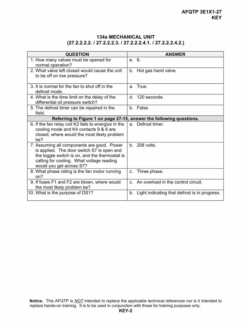
AFQTP 3E1X1-27 KEY
134a MECHANICAL UNIT (27.2.2.2.2. / 27.2.2.2.3. / 27.2.2.2.4.1. / 27.2.2.2.4.2.)
QUESTION ANSWER
1. How many valves must be opened for normal operation?
e. 6.
2. What valve left closed would cause the unit to be off on low pressure?
b. Hot gas hand valve.
3. It is normal for the fan to shut off in the defrost mode.
a. True.
4. What is the time limit on the delay of the differential oil pressure switch?
d. 120 seconds.
5. The defrost timer can be repaired in the field.
b. False.
Referring to Figure 1 on page 27-15, answer the following questions. 6. If the fan relay coil K2 fails to energize in the
cooling mode and K4 contacts 9 & 6 are closed, where would the most likely problem be?
a. Defrost timer.
7. Assuming all components are good. Power is applied. The door switch S7 is open and the toggle switch is on, and the thermostat is calling for cooling. What voltage reading would you get across S7?
b. 208 volts.
8. What phase rating is the fan motor running on?
c. Three phase.
9. If fuses F1 and F2 are blown, where would the most likely problem be?
c. An overload in the control circuit.
10. What is the purpose of DS1? b. Light indicating that defrost is in progress.
Notice. This AFQTP is NOT intended to replace the applicable technical references nor is it intended to replace hands-on training. It is to be used in conjunction with these for training purposes only.
KEY-2

APPENDIX A
MEMORANDUM FOR HQ AFCESA/CEOF
139 Barnes Drive Suite 1 Tyndall AFB, FL 32403-5319
FROM: SUBJECT: Air Force Qualification Training Package Improvement 1. Identify module.
Module # and title__________________________________________________ 2. Identify improvement/correction section(s)
_____ STS Task Reference ______ Performance Checklist _____ Training Reference ______ Feedback _____ Evaluation Instructions ______ Format _____ Performance Resources ______ Other _____ Steps in Task Performance
3. Recommended changes--use a continuation sheet if necessary.
________________________________________________________________________________________________________________________________________________________________________________________________________________________________________________________________________________________________________________________________________________________________________________________________________________________________________________________________________________________________________________________________________________________________________________________________________
4. You may choose to call in your recommendations to DSN 523-6445 or FAX
DSN/Commercial 523-6488 or (850) 283-6488 or email [email protected]. 5. Thank you for your time and interest.
YOUR NAME, RANK, USAF Title/Position