Embed Size (px)
Citation preview

A I R - D R I V E N D O U B L E D I A P H R A G M P U M P S

A D V A N T A G E S . . . M A K E A L L - F L O F I R S T C H O I C E :
• Pumps Anything That Will Pour• Wide Range of Pump Types and Sizes• Patented Lube-Free Air System• Will Not Stall at Slow Speeds• 100% Tested Prior to Shipment• Self-Priming• Non-Electrical • Runs Dry Without Damage• Infinitely Variable Flow Rate• Intermittent Operation or Continuous Duty• Pumps Fluids Which Contain Particles• Pumps High Viscosity Fluids• Reduced Solvent Flash-Off• Simple Modular Design• Dual Manifold Capability for 1/4˝ to 1˝ Models• Parts Interchangeable Between Models and Sizes
A B O U TA L L - F L O
ALL-FLO is committed to thepursuit of designing and man-ufacturing the highest qualityproduct available to industry. Since the beginning in 1986,ALL-FLO engineers have usedtheir extensive knowledge oftoday’s engineered materials,advanced air system logic andmanufacturing techniques todevelop the superior group oflube-free, air-operateddiaphragm pumps found inthis catalog. Every pump isperformance engineered andquality built to provide trouble-free service under thetoughest conditions.
S I M P L E O P E R A T I O NDouble diaphragm pumps areoperated by compressed air orany non-flammable com-pressed gas. The pumpingstroke begins as air is deliv-ered by the air distributionsystem, putting pressure onone diaphragm and then theopposite diaphragm. The twodiaphragms are linked togetherby a common rod. The pump-ing stroke on one side issimultaneously the suctionstroke on the opposingdiaphragm alternately drawingfluid in one side while dis-charging fluid from the otherside.
PATENTED -
Covered by one or both:
Patent No. 5758563
Patent No. 5232352
P E R F O R M A N C E E N G I N E E R E D
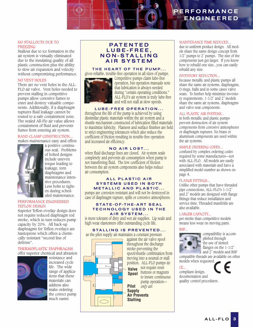
NO STALLOUTS DUE TO FREEZINGStallout due to ice formation in theair system is virtually eliminateddue to the insulating quality of allplastic construction plus the abilityto slow air expansion and velocitywithout compromising performance.
NO VENT HOLESThere are no vent holes in the ALL-FLO air valve. Vent holes needed toprevent stalling in competitivepumps allow corrosive fumes toenter and destroy valuable compo-nents. Additionally, if a diaphragmruptures fluid leakage cannot berouted to a safe containment zone.The sealed All-Flo air value allowscontainment of fluid and preventsfumes from entering air system.
BAND CLAMP CONSTRUCTION...makes maintenance easy and offers
a positive continu-ous seal. Problemsof bolted designsinclude uneventorque leading toleakage, torndiaphragms andmaintenance inten-sive procedures.Less bolts to tight-en during sched-uled maintenance.
PERFORMANCE ENGINEEREDTEFLON DESIGNSuperior Teflon overlay design doesnot require reduced diaphragm rodstroke, which in turn reduces pumpcapacity by 20%. All back-updiaphragms for Teflon overlays areSantoprene which offers a chemi-cally resistant “second line ofdefense”.
THERMOPLASTIC DIAPHRAGMSoffer superior chemical and abrasion
resistance andincreased cyclelife. The widerange of applica-tions that thesematerials canaddress alsomake orderingthe correct pumpmuch easier.
P A T E N T E D L U B E - F R E E ,
N O N - S T A L L I N G A I R S Y S T E M
T H E H E A R T O F T H E P U M P . . .gives reliable, trouble-free operation in all sizes of pumps.
Competitive pumps claim lube-freeoperation, but operation manuals notethat lubrication is always needed during “certain operating conditions.”ALL-FLO’s air system is truly lube-freeand will not stall at slow speeds.
L U B E - F R E E O P E R A T I O N . . .throughout the life of the pump is achieved by using dissimilar plastic materials within the air system and a shuttle mechanism constructed of lubrication filled materialsto maximize lubricity. Flatness and surface finishes are heldto strict engineering tolerances which also reduce the coefficient of friction resulting in trouble-free operation and increased air efficiency.
N O A I R L O S T . . .when fluid discharge lines are closed. Air system sealscompletely and prevents air consumption when pump is not transferring fluid. The low coefficient of frictionbetween the air system components also helps reduce air consumption.
A L L P L A S T I C A I R S Y S T E M S U S E D I N B O T H
M E T A L L I C A N D P L A S T I C . . .pumps are corrosion resistant and will not be destroyed incase of diaphragm rupture, spills or corrosive atmospheres.
S T A T E - O F - T H E - A R T S E A L T E C H N O L O G Y U S E D I N T H E
A I R S Y S T E M . . .is more tolerant of dirty and wet air supplies. Lip seals andhigh wear elastomers offer outstanding cycle life.
S T A L L I N G I S P R E V E N T E D . . .as the pilot supply air maintains a constant pressure
against the air valve spoolthroughout the dischargestroke preventing thespool/shuttle combination frommoving into a neutral or stallposition. ALL-FLO pumps do
not require reset buttons or magnets to insure continuouspump operation–– only air.
MAINTENANCE TIME REDUCED...due to uniform product design. All mod-els share the same design concept from1/2˝ pumps to 2˝ pumps. The size of thecomponents just get larger. If you knowhow to rebuild one size...you can easilyrebuild any size.
INVENTORY REDUCTION...because metallic and plastic pumps allshare the same air systems, diaphragms,O-rings, balls and in some cases valveseats. To further help minimize invento-ry requirements, 1-1/2˝ and 2˝ modelsshare the same air systems, diaphragmsand valve seat components.
ALL PLASTIC AIR SYSTEMS...in both metallic and plastic pumps prevent destruction of air system components from corrosive atmospheresor diaphragm ruptures. No brass or aluminum components are used withinthe air systems.
SIMPLE ORDERING CODES...confused by complex ordering codesrequired by some manufactures—not with ALL-FLO. All models are easilyassociated with materials and have asimplified model number as shown onpage 4.
FLANGE FITTINGS...Unlike other pumps that have threadedpipe connections, ALL-FLO’s 1-1/2˝and 2˝ models are designed with flangefittings that reduce installation and service time. Threaded manifolds are also available.
LARGER CAPACITY...per stroke than competitive modelsmeans less wear on moving parts.
BSP...compatibility is accom-plished through the use of slotted flanges on the 1-1/2˝ and 2˝ models and BSP
compatible threads are available on other models when requested.
CE...compliant design,documentation and quality control procedures.
3
ValveSpool
PilotSupplyAir PreventsStalling
A L L - F L O

P R O D U C T A N DM A T E R I A L S G U I D E
NOTE: Always check chemical resistance guide for compatibility. Do not use aluminum with halogenated solvents. Chemical resistance values may vary for fiberglass reinforced plastic. See your distributor for material substitutions.
NC The NC Model is the most economical choice for all non-aggressive,water-based liquids and slurries. Water-based inks, paints, adhesives andceramic slurries are some common applications. Polypropylene offersexcellent abrasion resistance and zero water absorption.
BK The BK Model is often used in corrosive environments. Inorganicacids, bases, plating solutions, alcohols and most water-soluble chemicals.The 1˝ and larger polypropylene pumps have fiberglass reinforcement forstructural integrity. Do not use with hydrofluoric acid or other fluids notrecommended for use with fiberglass.
RD The RD Model is often used for lubricants, oils and fats (both animaland vegetable types) hydrocarbons. Nylon offers superior resistance to thatof acetal in the area of solvents and solvent-based products. Groundableconductive nylon is also available for the transfer of flammable fluids.
KN PVDF used in the KN Model handles a wide range of chemicals,strong acids, bases, phenols, organic and inorganic chemicals at tempera-tures up to 200o F (93o C). PVDF complies with the FDA 3A materialspecifications.
AL The aluminum Model contains aluminum that is an A380 class material that does not require anodizing, impregnation or painting forappearance or wear characteristics. Do not use aluminum with halogenatedsolvents. Aluminum/Teflon models are built with nylon valve seats. Otheraluminum models are built with polypropylene valve seats. Note: Nitrile (Buna-N) and EPDM valve seats are available for 1-1/2 ˝ and 2 ˝ models.
ST 316 Stainless Steel Models are used where the mechanical propertiesof 316 stainless steel are required.
1/4˝ 1/2˝ 1˝ 1-1/2˝ 2 ˝ Wetted Material Air System 0-4 GPM 0-14 GPM 0-40 GPM 0-95 GPM 0-150 GPM
Page 6 Page 7 Page 8 Page 9 Page 10
Polypropylene w/Geolast* (Nitrile) Polypropylene NC-025 NC-5 NC-10 NC-15 NC-20Polypropylene w/Teflon* Polypropylene BK-025 BK-5 BK-10 BK-15 BK-20Polypropylene w/Santoprene* (EPDM) Polypropylene NC-025E BK-5E BK-10E BK-15E BK-20EPolypropylene w/Viton* Polypropylene BK-5V BK-10V
Nylon w/Teflon Nylon or Polypropylene RD-025 RD-5 RD-10 RD-20Conductive Nylon w/Teflon Nylon or Polypropylene CN-025 CN-5Conductive Nylon w/Geolast (Nitrile) Nylon or Polypropylene CN-025B CN-5B
PVDF w/Teflon Polypropylene KN-025 KN-5 KN-10 KN-15 KN-20PVDF w/Santoprene (EPDM) Polypropylene KN-025E KN-5E KN-10E KN-15E KN-20EPVDF W/Viton Polypropylene KN-5V KN-10V
Aluminum w/Geolast (Nitrile)/Polypro Polypropylene AL-5 AL-10 AL-15 AL-20Aluminum w/Teflon/Nylon Nylon or Polypropylene AL-5T AL-10T AL-15T AL-20TAluminum w/Santoprene(EDPM)/Polypro Polypropylene AL-5E AL-10E AL-15E AL-20E316 Stainless Steel w/Teflon Polypropylene ST-5 ST-10 ST-15 ST-20316 Stainless Steel w/Santoprene(EPDM) Polypropylene ST-5E ST-10E ST-15E ST-20E316 Stainless Steel w/Geolast (Nitrile) Polypropylene ST-5B ST-10B ST-15B ST-20B
* Note: For 2 ˝ Aluminum w/ Threaded Port Add -P28 to Model No.
FASTENER MATERIAL NC Plated & 302-304 Stainless Steel RD Plated & 302-304 Stainless Steel KN 302-304 Stainless SteelAL Plated & 302-304 Stainless Steel BK 302-304 Stainless SteelST 302-304 Stainless Steel * Teflon Coated Fasteners Available
4 A L L - F L O
D I A P H R A G M N O T E SGeolast is a nitrile based thermoplastic elastomer used in place of nitrile (Buna-N) orneoprene and urethane for non-aggressive water-based applications.Santoprene is an EPDM-based thermoplastic elastomer and is resistant to mild acids,some solvents and bases.Both Geolast and Santoprene offer superior cycle life, abrasion resistance and extend-ed chemical resistance in comparison to cloth reinforced rubber diaphragms.Teflon–stock models feature a two part diaphragm system. Bonded single piece diaphragms are available.*Santoprene and Geolast are registered trademarks of Advanced Elastomer Systems. Teflon and Viton are registered trademarks of DuPont Dow Elastomers.
ACCESSORIESA I R O P E R AT E DP I N C H VA LV E S
D R U M K I T S
Pinch valves are ideal for any fluidthat is abrasive or contains debris orlarge solid particles that would damage conventional valves.Available in 1/2 ˝ and 1˝ sizes in acomplete range of engineered plastics.
Filter/Regulators and SurgeSuppressors are available.
Drum pump kits are available for1/4 ˝ 1/2 ˝ and 1 ˝ plastic pumps.The pumps are supplied with bungadapter and suction tube. Manifoldsare prepositioned for immediateassembly.

S E L E C T I O N G U I D E
As you can see from the diagram above, as viscositiesincrease, the capacity of the pump decreases. Do notexceed 22,000 centapoise or 100,000 saybolt seconds onall 1/2˝ to 2˝ pumps. Do not exceed 10,000 centapoise or50,000 saybolt seconds on 1/4˝ models.
Some points to remember when pumping high viscosities:
1. Position the pump close to or below the level of the fluid source.
2. Suction lines should be increased in size–up to threetimes the size of the pump manifold inlet. Dual mani-folds may be used when available.
3. Start the pump slowly using a control valve on the air line.
4. Maximum air pressure required is reached when increasing the air pressure does not increase the flowrate.
5. If greater capacity is required, select a larger pump.
READING THE PUMP CURVEYou must know the following data:1. Required discharge pressure.2. Air pressure available at the
air inlet of the pump.3. Required flow rate.
TO OBTAIN DISCHARGE PRESSURE:Using the performance chart for a 1/2˝pump shown: If 80 psi is available at theair inlet and the required capacity of thepump is 6 GPM. Follow the blue concavecurve at 80 psi as it slopes to the rightand intersects with the 6 GPM vertical line
By tracking horizontally back to the left(Y) axis, the discharge pressure is ascer-tained--65 psi . (Right axis converts PSIto feet/meters).
TO OBTAIN REQUIRED AIR INLETPRESSURE:Reverse the steps above:Choose required discharge pressure (65 psi) on left (Y) axis,go directly across the graph to the intersection of the correct flowrate (6 GPM) , then track up and back toward the left (Y) axisalong the blue curve; and the correct required air pressure can beobtained (80 psi).Note: If greater outlet pressure vs. air inlet pressure is required--select a larger pump.
TO OBTAIN AIR CONSUMPTION:The convex red lines represent the air consumption (standardcubic feet per minute), and the closest red line to where the blueline and the flow rate intersect represents the air capacityrequired. On our example, the air consumption would be approx-imately 6 SCFM.
To convert SCFM to m3/h (N) multiply by 1.7
0 6 102
DISCHARGE FLOW-Liters/Min.7,6 15,2 60,8
20(1,3)
40(2,7)
60(4,1)
80(5,4)
100(6,8)
230(69,9)
184(55,9)
138(41,9)
92(27,9)
46(13,9)
TOTA
L H
EA
D IN
FE
ET
(M
ET
ER
S)
PR
ES
SU
RE
INL
ET
/OU
TL
ET
PS
IG (
BA
RS
)
15
52 10
DISCHARGE FLOW-U.S. Gals./Min (GPM)
53,222,8 30,4 45,638,0
4 8 12 14 16
AIR CONSUMPTION - SCFM
123
INSTALLATION1. A lube-free, clean, dry compressed air source (or any non-flammable, compressed gas) is recommended. Use a filter thatis capable of filtering out particles larger than 50 microns.
2. Pumps should be mounted in an upright position with theexception of the 1/4˝ models which may be rotated 360° tosuit the application.
3. Install a particle fluid filter on the fluid suction line whenparticles in the fluid exceed the maximum particle size specifi-cation of the pump or particles are sharp enough to cut thediaphragms.
4. Never restrict fluid suction lines by means of a reduced pipesize (smaller than pump inlet size) or control the pump withvalves on the fluid inlet side of the pump.
5. Limit fluid inlet pressure to 10 PSIG or (.68 BAR)
Performance Chart
20000
20%
40%
60%
80%
100%
Centapoise
Saybolt Seconds40000 60000 80000 100000
2000 4000 6000 8000 10000 12000 14000 16000 18000 20000 22000
Ca
pa
cit
y
5A L L - F L O
1
2
2
3
3
2
1
HIGH VISCOSITY APPLICATIONS

0 2 3 4 51
DISCHARGE FLOW-Liters/Min.3,8 7,6 11,4 15,2 19,0
20(1,3)
40(2,7)
60(4,1)
80(5,4)
100(6,8)
230(69,9)
184(55,9)
138(41,9)
92(27,9)
46(13,9)
TOTA
L H
EA
D IN
FE
ET
(M
ET
ER
S)
PR
ES
SU
RE
INL
ET
/OU
TL
ET
PS
IG (
BA
RS
)
43
21AIR CONSUMPTION - SCFM
DISCHARGE FLOW-U.S. Gals./Min.
PLASTIC MODELS:NC-025 (Polypropylene/Geolast*) 5 lbs. (2,3 kg.)BK-025 (Polypropylene/Teflon) 5 lbs. (2,3 kg.)RD-025 (Nylon/Teflon) 5 lbs. (2,3 kg.)KN-025 (PVDF/Teflon) 7 lbs. (3,2 kg.)Optional elastomers and conductive nylon are available.* Geolast properties are similar to that of Nitrile (Buna-N)
See page 4 for complete model listing.
SPECIFICATIONS:Capacity:Adjustable. . . . . . 0 to 4.3 GPM (16,3 liters/min.)
Maximum Temperature:KN-025 Model . . . . . . . . . . . . . . . . 200°F (93°C)Other Models . . . . . . . . . . . . . . . . . 150°F (66°C)
Maximum Air Pressure:All Models . . . . . . . . . . . . . . . 100 PSI (6,8 bars)
Minimum Air Pressure:All Models . . . . . . . . . . . . . . . . 20 PSI (1,2 bars)
Dry Lift Capacity @ 100 PSI (6,8 bars):Models w/Teflon Seats . . . . . . . . 17 ft. (5 meters)Other Models . . . . . . . . . . . . . . . 20 ft. (6 meters)
Maximum Solids: . . . . . . . . . . . 1⁄16˝ or (1,6 mm)Air Supply:Inlet . . . . . . . . . . . . . . . . . . . . . 1⁄4˝ NPT FemaleOutlet . . . . . . . . . . . . . . . . . . . . 1⁄4˝ NPT Female(Air flow control valve, 1/4˝ NPT Female)
Fluid Inlet/Discharge: . . . . . . . . . . . . . . . 1⁄4˝ NPT
Footnotes:• Muffler supplied with each pump• BSP threads available upon request• 1/4˝ pumps are not shipped with an air flow
control valve.• Dual manifold inlet/outlet capability may be ordered from the factory
PERFORMANCE CURVE (Based on water-flooded suction)
2.38(60.5)
AIREXHAUST
6.38(162.0)
7.25(184.2)
.38 DIA-4 SLOTS(9.6)
1.63(41.4)
4.75(121.0)
5.34(135.6)
AIR INLET
7.63(193.8)
2.88(73.2)
( )
DISCHARGE
SUCTION
4.59(116.8)
5.50*(139.7)
1.15(29.2)
PLASTIC Dimensions in inches and (mm).
*Approximate Dimension with Muffler–– 06.18 (157.0)
1 ⁄4”
Front ViewSide View
Rear View Footprint
6 A L L - F L O

PLASTIC MODELS:NC-5 (Polypropylene/Geolast*) 8 lbs. (3,6 kg.)BK-5 (Polypropylene/Teflon) 8 lbs. (3,6 kg.)RD-5 (Nylon/Teflon) 8 lbs. (3,6 kg.)SL-5 (Acetal/Geolast) 8 lbs. (3,6 kg.)KN-5 (PVDF/Teflon) 11 lbs. (4,9 kg.)
METALLIC MODELS:AL-5 (Aluminum) 8.5 lbs. (3,8 kg.)ST-5 (316 Stainless Steel) 16 lbs. (7,2 kg.)Optional elastomers and conductive nylon available.* Geolast properties are similar to that of Nitrile (Buna-N)
See page 4 for complete model listing.
SPECIFICATIONS:Capacity:Adjustable . . . . . . 0 to 14 GPM (53,2 liters/min.)
Maximum Temperature:KN-5 Model . . . . . . . . . . . . . . . . . . 200°F (93°C)Other Plastic Models . . . . . . . . . . . . 150°F (66°C)Metallic Models . . . . . . . . . . . . . . . 200°F (93°C)
Maximum Air Pressure:All Models . . . . . . . . . . . . . . . 100 PSI (6,8 bars)
Minimum Air Pressure:All Models . . . . . . . . . . . . . . . . 20 PSI (1,2 bars)
Dry Lift Capacity @ 100 PSI (6,8 bars):Models w/Teflon Balls . . . . . . . . 10 ft. (3 meters)Other Models . . . . . . . . . . . . . 15 ft. (4,5 meters)
Maximum Solids: . . . . . . . . . . . . 1⁄8˝ or (3,1 mm)Air Supply:Inlet . . . . . . . . . . . . . . . . . . . . . 1⁄4˝ NPT FemaleOutlet . . . . . . . . . . . . . . . . . . . . 3⁄8˝ NPT Female(Air flow control valve, 1/4˝ NPT or 1/2˝ BSP Female)
Fluid Inlet/Discharge:Plastic Models . . . . . . . . . . . . . . 1⁄2˝ NPS FemaleMetallic Models. . . 1⁄2˝ NPS Female & 3/4˝ NPS Male(BSP or NPT Compatible)
Footnotes:• Muffler supplied with each pump• Air flow control valve supplied with each pump• Dual manifold inlet/outlet capability
0 6 102
DISCHARGE FLOW-Liters/Min.7,6 15,2 60,8
20(1,3)
40(2,7)
60(4,1)
80(5,4)
100(6,8)
230(69,9)
184(55,9)
138(41,9)
92(27,9)
46(13,9)
TOTA
L H
EA
D IN
FE
ET
(M
ET
ER
S)
PR
ES
SU
RE
INL
ET
/OU
TL
ET
PS
IG (
BA
RS
)
15
52 10
DISCHARGE FLOW-U.S. Gals./Min.
53,222,8 30,4 45,638,0
4 8 12 14 16
AIR CONSUMPTION - SCFM
PERFORMANCE CURVE (Based on water-flooded suction)
10.75(273.0)
AIR INLET
9.76(248.0)
9.38(238.0)
5.70(145.0)
DISCHARGE
SUCTION
0.31 DIA-4 SLOTS(8.0)
6.19(157.2)
1.38(35.0)
6.70(170.0)
4.00(102.0)
7.50*(190.5)
5.12(130.0)
AIREXHAUST
3.26(102.0)
PLASTIC Dimensions in inches and (mm). Ports shown facing front for dimensional purposes.
*Approximate Dimension with Muffler–– 8.00 (203.2)
7A L L - F L O
1 ⁄2”
8.34(212.0)
AIR INLET
10.86(276.0)
7.82(198.6)
4.40(112.0)
DISCHARGE
INLET
0.28 DIA-4 SLOTS(7.0)
5.21(132.0)
28.6(1.13)
5.40(137.0)
5.43(138.0)
METALLIC
4.00(102.0)
7.50*(190.5)
4.14(105.0)
AIREXHAUST
3.24(82.0)

0 10 25 405
DISCHARGE FLOW-Liters/Min.19 38 152
20(1,3)
40(2,7)
60(4,1)
80(5,4)
100(6,8)
230(69,9)
184(55,9)
138(41,9)
92(27,9)
46(13,9)
TOTA
L H
EA
D IN
FE
ET
(M
ET
ER
S)
PR
ES
SU
RE
INL
ET
/OU
TL
ET
PS
IG (
BA
RS
)
10
DISCHARGE FLOW-U.S. Gals./Min.
13357 76 11495
15 20 3530
1520
40
30 AIR CONSUMPTION - SCFM
PLASTIC MODELS:NC-10 (Polypropylene/Geolast*) 19 lbs. (8,6 kg.)BK-10 (Polypropylene/Teflon) 19 lbs. (8,6 kg.)RD-10 (Nylon/Teflon) 19 lbs. (8,6 kg.)SL-10 (Acetal/Geolast) 19 lbs. (8,6 kg.)KN-10(PVDF/Teflon) 22 lbs. (9,9 kg.)
METALLIC MODELS:AL-10 (Aluminum) 19 lbs. (8,6 kg.)ST-10 (316 Stainless Steel) 42 lbs. (19,1kg.)Optional elastomers available.* Geolast properties are similar to that of Nitrile (Buna-N)
See page 4 for complete model listing.
SPECIFICATIONS:Capacity:Adjustable. . . . . . . 0 to 40 GPM (152 liters/min.)
Maximum Temperature:KN-10 Model . . . . . . . . . . . . . . . . . 200°F (93°C)Other Plastic Models. . . . . . . . . . . . 150°F (66°C)Metallic Models . . . . . . . . . . . . . . . 200°F (93°C)
Maximum Air Pressure:KN-10 Model . . . . . . . . . . . . . . 70 PSI (4,8 bars)Other Models . . . . . . . . . . . . . 100 PSI (6,8 bars)
Minimum Air Pressure:All Models . . . . . . . . . . . . . . . . 20 PSI (1,2 bars)
Dry Lift Capacity @ 100 PSI (6,8 bars):Models w/Teflon Balls . . . . . . . . 10 ft. (3 meters)Other Models . . . . . . . . . . . . . 15 ft. (4,5 meters)
Maximum Solids: . . . . . . . . . . . . 1⁄4˝ or (6,4 mm)Air Supply:Inlet . . . . . . . . . . . . . . . . . . . . . 1⁄4˝ NPT FemaleOutlet . . . . . . . . . . . . . . . . . . . . 3⁄4˝ NPT Female(Air flow control valve, 1/4˝ NPT or 1/2˝ BSP Female)
Fluid Inlet/Discharge: . . . . . . . . . . . . . . . . 1˝ NPT
Footnotes:• Muffler supplied with each pump• Air flow control valve supplied with each pump• Dual manifold inlet/outlet capability –
Plastic models only• BSP threads available upon request
PERFORMANCE CURVE
AIR INLET
12.00(305.0)
DISCHARGE
SUCTION
15.50(394.0)
13.50(343.0)
2.00(51.0)
5.74(146.0)
7.62(194.0)
.44 DIA-4 HOLES(11.2)
8.30(211.0)
8.30(211.0)
4.18(106.0)
6.00(152.4)
AIREXHAUST
9.90*(252.0)
PLASTIC
AIR INLET
6.00(153.0)
12.00(305.0)
DISCHARGE
SUCTION
1.44(37.0)
12.69(322.0)
11.78(299.0)
6.76(172.0) .44 DIA-4 HOLES
(11.2)
7.14(181.0)
7.80(198.0)
5.68(144.0)
9.95*(253.0)
5.00(127.0)
AIREXHAUST
4.18(106.0)
METALLIC
Dimensions in inches and (mm). Ports shown facing front for dimensional purposes.1”
8 A L L - F L O
*Approximate Dimension with Muffler–– 11.57 (293.9)
*Approximate Dimension with Muffler–– 11.57 (293.9)

*Approximate Dimension with Muffler–– 14.88 (378.0)
0 40 6020
DISCHARGE FLOW-Liters/Min.76
20(1,3)
40(2,7)
60(4,1)
80(5,4)
100(6,8)
230(69,9)
184(55,9)
138(41,9)
92(27,9)
46(13,9)
TOTA
L H
EA
D IN
FE
ET
(M
ET
ER
S)
PR
ES
SU
RE
INL
ET
/OU
TL
ET
PS
IG (
BA
RS
)
DISCHARGE FLOW-U.S. Gals./Min.80 100
AIR CONSUMPTION - SCFM
152 228 304 380
3050
10
70
PLASTIC MODELS:NC-15 (Polypropylene/Geolast*) 52 lbs. (23,6 kg.)BK-15 (Polypropylene/Teflon) 52 lbs. (23,6 kg.)KN-15 (PVDF/Teflon) 66 lbs. (30 kg.)
METALLIC MODELS:AL-15 (Aluminum) 61 lbs. (27,7 kg.)ST-15 (316 Stainless Steel) 131 lbs. (59 kg.)Optional elastomers available.* Geolast properties are similar to that of Nitrile (Buna-N)
See page 4 for complete model listing.
SPECIFICATIONS:Capacity:Adjustable. . . . . . 0 to 150 GPM (569 liters/min.)
Maximum Temperature:KN-15 Model . . . . . . . . . . . . . . . . . 200°F (93°C)Other Plastic Models. . . . . . . . . . . . 150°F (66°C)Metallic Models . . . . . . . . . . . . . . . 200°F (93°C)
Maximum Air Pressure:KN-15 Model . . . . . . . . . . . . . . 70 PSI (4,8 bars)Other Models . . . . . . . . . . . . . 100 PSI (6,8 bars)
Minimum Air Pressure:All Models . . . . . . . . . . . . . . . . 20 PSI (1,2 bars)
Dry Lift Capacity @ 100 PSI (6,8 bars):Models w/Teflon Balls . . . . . . . . 10 ft. (3 meters)Other Models . . . . . . . . . . . . . 15 ft. (4,5 meters)
Maximum Solids: . . . . . . . . . . . . 1⁄4˝ or (6,4 mm)Air Supply:Inlet . . . . . . . . . . . . . . . . . . . . . 3⁄4˝ NPT FemaleOutlet . . . . . . . . . . . . . . . . . . . . 3⁄4˝ NPT Female(Air flow control valve, 3/4˝ NPT or BSP Female)
Footnotes:• Muffler supplied with each pump• Air flow control valve supplied with each pump• Flanges are ANSI and DIN compatible• Flange mounting requires (4) bolts: 5/8˝x 4-1/2˝• Threaded companion flanges available
PERFORMANCE CURVE
AIRINLET
19.50(495.0)
DISCHARGE
SUCTION
20.50(518.0)
17.50(445.0)
11.50(292.0)
11.15(283.0)
3.19(81.0)
0.56 DIA-4 SLOTS(14.2)
9.31(236.4)
11.56*(302.0)
6.00(152.4)
5.00(63.5)
11.00(279.4)
AIREXHAUST
METALLIC
11⁄2”
9A L L - F L O
AIRINLET
20.34(516.6)
DISCHARGE
SUCTION
21.12(536.5)
18.25(463.6)
11.47(291.4)
11.18(284.0)
3.12(79.2)
0.56 DIA-4 SLOTS(14.2)
9.34(237.2)
11.88(302.0)
8.06(204.8)
7.06(179.2)
11.47(291.4)
AIREXHAUST
PLASTIC Dimensions in inches and (mm).). Ports shown facing front for dimensional purposes.

0 40 6020
DISCHARGE FLOW-Liters/Min.76
20(1,3)
40(2,7)
60(4,1)
80(5,4)
100(6,8) 230
(69,9)
184(55,9)
138(41,9)
92(27,9)
46(13,9)
TOTA
L H
EA
D IN
FE
ET
(M
ET
ER
S)
PR
ES
SU
RE
INL
ET
/OU
TL
ET
PS
IG (
BA
RS
)
30
DISCHARGE FLOW-U.S. Gals./Min.80 100 120 140 160
AIR CONSUMPTION - SCFM
152 228 304 380 456 532 608
50
70
PLASTIC MODELS:NC-20 (Polypropylene/Geolast*) 54 lbs. (23,6 kg.)BK-20 (Polypropylene/Teflon) 54 lbs. (23,6 kg.)RD-20 (Nylon/Teflon) 54 lbs. (23,6 kg.)KN-20 (PVDF/Teflon) 68 lbs. (30 kg.)
METALLIC MODELS:AL-20 (Aluminum) 61 lbs. (27,7 kg.)ST-20 (316 Stainless Steel) 131 lbs. (59 kg.)Optional elastomers available.* Geolast properties are similar to that of Nitrile (Buna-N)
See page 4 for complete model listing.
SPECIFICATIONS:Capacity:Adjustable. . . . . . 0 to 150 GPM (569 liters/min.)
Maximum Temperature:KN-20 Model . . . . . . . . . . . . . . . . . 200°F (93°C)Other Plastic Models. . . . . . . . . . . . 150°F (66°C)Metallic Models . . . . . . . . . . . . . . . 200°F (93°C)
Maximum Air Pressure:KN-20 Model . . . . . . . . . . . . . . 70 PSI (4,8 bars)Other Models . . . . . . . . . . . . . 100 PSI (6,8 bars)
Minimum Air Pressure:All Models . . . . . . . . . . . . . . . . 20 PSI (1,2 bars)
Dry Lift Capacity @ 100 PSI (6,8 bars):Models w/Teflon Balls . . . . . . . . 10 ft. (3 meters)Other Models . . . . . . . . . . . . . 15 ft. (4,5 meters)
Maximum Solids: . . . . . . . . . . . . 1⁄4˝ or (6,4 mm)Air Supply:Inlet . . . . . . . . . . . . . . . . . . . . . 3⁄4˝ NPT FemaleOutlet . . . . . . . . . . . . . . . . . . . . 3⁄4˝ NPT Female(Air flow control valve, 3/4˝ NPT or 3/4˝ BSP Female)
Add -P28 to Model No. for 2˝(51mm) NPT Female
Fluid Inlet/Discharge: . . . . . . . . 2˝ (51mm)FlangeFootnotes:• Muffler supplied with each pump• Air flow control valve supplied with each pump• Flanges are ANSI and DIN compatible• Flange mounting requires (4) bolts: 5/8˝ x 4-1/2˝• Threaded companion flanges available
PERFORMANCE CURVE
20.62(523.80)
DISCHARGE
SUCTION
26.00(660.4)
23.00(584.2)
13.25(336.6)
14.00(355.6)
0.56 DIA- 4 SLOTS(14.2)
3.50(89.0)
12.00(304.8)
AIREXHAUST
11.56*(302.0)
6.00(152.4)
12.75(324.0)
5.00(63.5)
PLASTIC
AIRINLET
A
DISCHARGE
SUCTION
E
D
C
G
B
FH DIA- 4 SLOTS
M
L
AIREXHAUST
K
J
METALLIC flange or threaded
2”
10 A L L - F L O
Dimensions in inches and (mm). Ports shown facing front for dimensional purposes.
*Approximate Dimension with Muffler–– 14.88 (378.0)
*Approximate Dimension with Muffler–– 14.88 (378.0)
MODEL DIMENSIONS Inches / (mm)SIZE (Inlet/Outlet) A B C D E F G H J K L M
AL-20 Flanged 19.50 3.50 13.25 21.62 24.62 12.00 13.85 0.56 11.88 12.75 5.00 6.002˝ Flange 2˝ Flange (495.0) (89.0) (336.6) (549.2) (625.3) (304.8) (351.5) (14.2) (301.8) (324.0) (63.5) (152.4)AL-20-P28 Threaded 19.50 1.88 13.25 24.75 26.10 10.06 12.00 0.56 11.88 12.75 5.00 6.00
2˝ NPT 2˝ NPT (495.0) (47.6) (336.6) (629.0) (663.0) (255.5) (304.8) (14.2) (301.8) (324.0) (63.5) (152.4)

Thousands of ALL-FLO pumps are providing trouble-free service on all types of applications throughout industry. Whatever the application, industry or operating environment,
your ALL-FLO distributor is ready to help you select the right pumpfor your application and work with you to ensure trouble-free operation.
E A C H A L L - F L O P U M P I S B A C K E D B Y A 5 - Y E A R W A R R A N T Y A N D T E S T E D B E F O R E S H I P M E N T .
Your All-Flo Double Diaphragm Pump is warranted to the original user against defects in workmanship or materials under normal use (rental useexcluded) for five years after purchase date. Any pump which is determined to be defective in material and workmanship andreturned to All-Flo Pump Co., shipping costs prepaid, will be repaired or replaced at All-Flo's option.
This warranty does not cover failure of parts or components due to normal wear or damage or failure which in thejudgment of All-Flo arises from misuse, abrasion, corrosion, negligence, accidental damage, faulty installation ortampering. If All-Flo inspection discloses no defect in material or workmanship, repair or replacement and return willbe made at customary charges.
All-Flo has made a diligent effort to accurately illustrate and describe its product in this literature. However, such illustra-tions and descriptions are not a warranty. THE ABOVE EXPRESS WARRANTY IS IN LIEU OF AND EXCLUDES ALLOTHER WARRANTIES, EXPRESS OR IMPLIED, INCLUDING, WITHOUT LIMITATION, MERCHANTABILITY OR FITNESS FOR A PARTICULARPURPOSE.
Purchaser shall give written notice of any claim to All-Flo within ten days after discovery of any alleged defect. ALL-FLO SHALL NOT BELIABLE FOR CONSEQUENTIAL DAMAGES, LOSSES, DELAYS, LABOR COSTS OR ANY OTHER EXPENSE DIRECTLY OR INDIRECTLY ARISINGFROM USE OF THE PUMP, ITS LIABILITY BEING EXPRESSLY LIMITED TO THE REPLACEMENT OR REPAIR OF ANY DEFECTIVE PUMP ORAN ALLOWANCE OF CREDIT THEREFORE. THE REMEDY AND RECOVERY OF THE PURCHASER ON ANY CLAIM AGAINST ALL-FLO,WHETHER BASED ON CONTRACT, THIS WARRANTY OR ANY ALLEGED NEGLIGENCE SHALL BE AS STATED AND LIMITED HEREIN ANDSHALL BE EXCLUSIVE.
5YEAR
WARRANTY
11A L L - F L O
B U I L T F O R T H ER E A L W O R L D

A L L - F L O P U M P C O M P A N Y , I N C .9321 Pineneedle DriveMentor, Ohio 44060
Phone: 440.354.1700 Fax: 440.354.9466
Business Site: www.all-flo.com E-Mail: [email protected] AF-111
Printed in U.S.A.


![Air Purification Keeps Pets and People Happy · "Since installing the air purification equipment in our HVAC equipment, odors [in our] greeting and gift shop [areas] have been eliminated,”](https://img.pdfslide.us/doc/110x75/5ff59ab7d788ca0d163972f2/air-purification-keeps-pets-and-people-happy-since-installing-the-air-purification.jpg)