Embed Size (px)
Citation preview
Inverter PairWall Mounted Type E-Series
[Applied Models]Inverter Pair : Heat Pump
SiBE04 - 624
SiBE04-624
Table of Contents i
Inverter PairE-Series
Heat Pump
Indoor Units
FTXR28EV1BFTXR42EV1BFTXR50EV1B
Outdoor Units
RXR28EV1BRXR42EV1BRXR50EV1B
SiBE04-624
ii Table of Contents
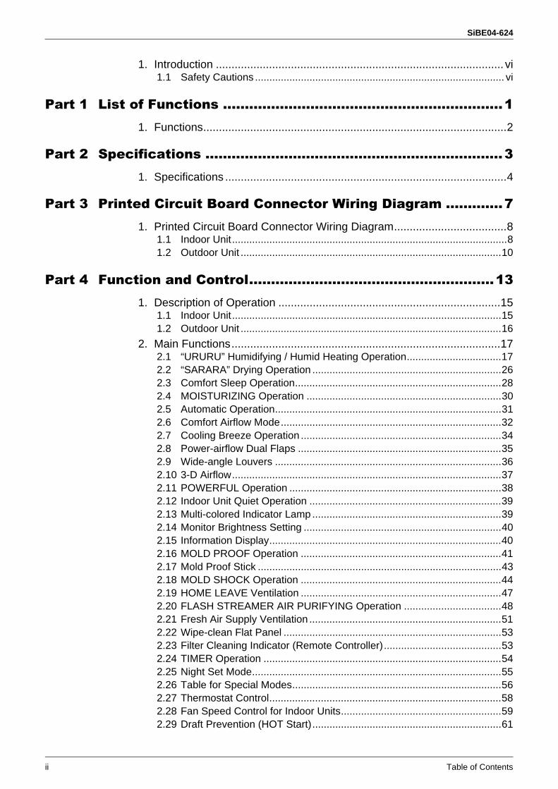
1. Introduction ............................................................................................ vi1.1 Safety Cautions ....................................................................................... vi
Part 1 List of Functions ................................................................11. Functions.................................................................................................2
Part 2 Specifications ....................................................................31. Specifications ..........................................................................................4
Part 3 Printed Circuit Board Connector Wiring Diagram .............71. Printed Circuit Board Connector Wiring Diagram....................................8
1.1 Indoor Unit................................................................................................81.2 Outdoor Unit ...........................................................................................10
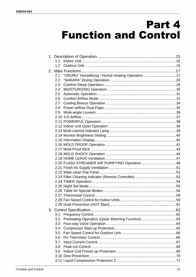
Part 4 Function and Control........................................................131. Description of Operation .......................................................................15
1.1 Indoor Unit..............................................................................................151.2 Outdoor Unit ...........................................................................................16
2. Main Functions......................................................................................172.1 “URURU” Humidifying / Humid Heating Operation.................................172.2 “SARARA” Drying Operation ..................................................................262.3 Comfort Sleep Operation........................................................................282.4 MOISTURIZING Operation ....................................................................302.5 Automatic Operation...............................................................................312.6 Comfort Airflow Mode.............................................................................322.7 Cooling Breeze Operation ......................................................................342.8 Power-airflow Dual Flaps .......................................................................352.9 Wide-angle Louvers ...............................................................................362.10 3-D Airflow..............................................................................................372.11 POWERFUL Operation ..........................................................................382.12 Indoor Unit Quiet Operation ...................................................................392.13 Multi-colored Indicator Lamp ..................................................................392.14 Monitor Brightness Setting .....................................................................402.15 Information Display.................................................................................402.16 MOLD PROOF Operation ......................................................................412.17 Mold Proof Stick .....................................................................................432.18 MOLD SHOCK Operation ......................................................................442.19 HOME LEAVE Ventilation ......................................................................472.20 FLASH STREAMER AIR PURIFYING Operation ..................................482.21 Fresh Air Supply Ventilation ...................................................................512.22 Wipe-clean Flat Panel ............................................................................532.23 Filter Cleaning Indicator (Remote Controller).........................................532.24 TIMER Operation ...................................................................................542.25 Night Set Mode.......................................................................................552.26 Table for Special Modes.........................................................................562.27 Thermostat Control.................................................................................582.28 Fan Speed Control for Indoor Units........................................................592.29 Draft Prevention (HOT Start)..................................................................61
SiBE04-624
Table of Contents iii
3. Control Specification .............................................................................623.1 Frequency Control..................................................................................623.2 Preheating Operation (Quick Warming Function) ..................................633.3 Four-way Valve Operation......................................................................643.4 Compressor Start up Protection .............................................................653.5 Fan Speed Control for Outdoor Unit.......................................................663.6 Fin Thermistor Control............................................................................663.7 Input Current Control..............................................................................673.8 Peak-cut Control.....................................................................................683.9 Indoor Coil Freeze-up Protection ...........................................................693.10 Dew Prevention ......................................................................................703.11 Liquid Compression Protection 2 ...........................................................713.12 Discharge Pipe Temperature Control.....................................................723.13 Automatic Defrosting ..............................................................................733.14 Electronic Expansion Valve Control .......................................................75
Part 5 System Configuration.......................................................811. Installation Manual ................................................................................82
1.1 Indoor Units ............................................................................................821.2 Outdoor Units .........................................................................................96
2. System Configuration..........................................................................1063. Instruction............................................................................................107
3.1 Safety Precautions ...............................................................................1073.2 Names and Functions of Parts .............................................................1083.3 Preparation before Operation...............................................................1103.4 Cooling · “SARARA” DRYING Operation .............................................1123.5 Heating · “URURU” HUMIDIFYING Operation .....................................1133.6 AUTO / MOISTURIZING Operation .....................................................1143.7 Adjusting Airflow Direction · Comfort Airflow Mode · Cooling Breeze ·
Airflow Rate ..........................................................................................1153.8 FLASH STREAMER AIR PURIFYING · FRESH AIR SUPPLY
VENTILATION Operation / HOME LEAVE VENTILATION ..................1163.9 TIMER Operation .................................................................................1173.10 COMFORT SLEEP / POWERFUL Operation ......................................1183.11 SET UP ................................................................................................1193.12 MOLD PROOF Operation ....................................................................1203.13 MOLD SHOCK Operation / INFORMATION DISPLAY ........................1213.14 Care and Cleaning ...............................................................................1223.15 Troubleshooting....................................................................................130
Part 6 Service Diagnosis...........................................................1351. Convenient Service Check Function ...................................................1372. Troubleshooting ..................................................................................139
2.1 Error Code Indication by Remote Controller ........................................1392.2 Air conditioner does not run. ................................................................1412.3 Air conditioner runs but does not get cooling (heating). .......................1432.4 When operation starts, safety breaker works. ......................................1452.5 Air conditioner makes big noise and vibration......................................1472.6 Air does not humidified enough............................................................1482.7 Indoor Unit PCB Fault ..........................................................................1502.8 Peak-cut Control or Freeze-up Protection............................................151
SiBE04-624
iv Table of Contents
2.9 Fan Motor System (DC Motor) Fault ....................................................1532.10 Streamer Unit Fault ..............................................................................1552.11 Thermistor System Fault ......................................................................1572.12 Front Panel Open / Close Fault............................................................1582.13 Humidity Sensor Fault ..........................................................................1592.14 Signal Transmission Error (Indoor Unit - Outdoor Unit) .......................1602.15 Incompatible Power Supply between Indoor Unit and Outdoor Unit ....1622.16 Incomplete Setting for Hose Length .....................................................1632.17 Outdoor Unit PCB Fault........................................................................1642.18 OL Activation (Compressor Overload) .................................................1652.19 Compressor Lock .................................................................................1662.20 DC Fan Lock ........................................................................................1672.21 Input Over Current Detection ...............................................................1682.22 Four Way Valve Fault...........................................................................1702.23 Discharge Pipe Temperature Control...................................................1722.24 High Pressure Control in Cooling .........................................................1732.25 Compressor Sensor System Fault .......................................................1752.26 Damper Fault........................................................................................1762.27 Position Sensor Fault ...........................................................................1772.28 DC Voltage / DC Current Sensor Fault ................................................1792.29 Thermistor System Fault ......................................................................1802.30 Abnormal Temperature in Electrical Box..............................................1822.31 Temperature Rise in Radiation Fin.......................................................1842.32 Output Overcurrent...............................................................................1862.33 Insufficient Gas.....................................................................................1882.34 Over Voltage Protection / Low Voltage Protection ...............................1902.35 Outdoor Unit PCB Fault or Communication Circuit Fault .....................1912.36 Signal Transmission Error on Outdoor Unit PCB .................................1942.37 Fan Motor System Fault / Fan Lock .....................................................1962.38 Heater Wire Fault .................................................................................1972.39 Humidification Fan Outlet Thermistor Fault /
Abnormal Heater Temperature.............................................................1992.40 Lights-out of Microcomputer Status Lamp............................................201
3. Check ..................................................................................................2023.1 Thermistor Resistance Check ..............................................................2023.2 Installation Condition Check.................................................................2033.3 Outdoor Fan System Check (DC Motor) ..............................................2033.4 Power Supply Waveform Check...........................................................2043.5 Capacitor Voltage Check......................................................................2043.6 Main Circuit Electrolytic Capacitor Check ............................................2053.7 Refrigerant System Check ...................................................................2053.8 “Inverter Checker” Check .....................................................................2063.9 Power Transistor Check .......................................................................2073.10 Discharge Pressure Check...................................................................2083.11 Electronic Expansion Valve Check.......................................................2093.12 Indoor Unit PCB Output Check ............................................................2103.13 Rotating Pulse Input on Outdoor Unit PCB Check ...............................2113.14 Humidity Sensor Check........................................................................2123.15 Main Circuit Short Check......................................................................2123.16 Four-way Valve Performance Check....................................................2133.17 Solenoid Valve for Dehumidification Check .........................................214
SiBE04-624
Table of Contents v
Part 7 Removal Procedure ........................................................2151. Indoor Unit...........................................................................................216
1.1 Removal of the Air Filters / Front panel................................................2161.2 Removal of the Upper Panel ................................................................2221.3 Removal of the Front Grille ..................................................................2251.4 Removal of the Assembly of the Open/Close Mechanism ...................2281.5 Removal of the Assembly of the Reduction Motor ...............................2301.6 Removal of the Electrical Box ..............................................................2331.7 Removal of the PCB.............................................................................2381.8 Removal of the Dehumidifying Solenoid Valve Coil .............................2441.9 Removal of the Connecting Duct..........................................................2451.10 Removal of the Drain Hose ..................................................................2471.11 Removal of the Swing Motor ................................................................2491.12 Removal of the Heat Exchanger ..........................................................2511.13 Removal of the Propeller Fan / Fan Motor ...........................................2541.14 Removal of Horizontal Blades / Vertical Blades ...................................2571.15 Removal of the Streamer Unit ..............................................................259
2. Outdoor Unit........................................................................................2632.1 Removal of the Humidify Unit...............................................................2632.2 Removal of the Heater Assembly / Humidifying Rotor
(Moisture Absorption Element) / Humidifying Rotor Motor ...................2662.3 Removal of the Humidifying Assembly.................................................2702.4 Removal of the Moisture Absorption Fan Motor...................................2732.5 Removal of the Propeller Fan / Fan Motor ...........................................2742.6 Removal of the Duct in Humidifier........................................................2792.7 Removal of the Electrical Box ..............................................................2802.8 Removal of the PCB.............................................................................2842.9 Removal of the Sound Blanket.............................................................2872.10 Remove the Thermistor Assembly .......................................................2892.11 Removal of the Reactor / Partition Plate ..............................................2912.12 Removal of the Four Way Valve...........................................................2922.13 Removal of the Expansion Valve .........................................................2942.14 Removal of the Compressor.................................................................295
Part 8 Others .............................................................................2971. Others .................................................................................................298
1.1 Test Run from the Remote Controller ..................................................2981.2 Field Setting .........................................................................................299
Part 9 Appendix.........................................................................3011. Piping Diagrams..................................................................................302
1.1 Indoor Units ..........................................................................................3021.2 Outdoor Units .......................................................................................302
2. Wiring Diagrams..................................................................................3032.1 Indoor Units ..........................................................................................3032.2 Outdoor Units .......................................................................................303
SiBE04-624
vi Table of Contents
Index ............................................................................................. i
Drawings & Flow Charts ............................................................... iii
SiBE04-624 Introduction
vii
1. Introduction1.1 Safety Cautions
Cautions and Warnings
Be sure to read the following safety cautions before conducting repair work.The caution items are classified into “ Warning” and “ Caution”. The “ Warning” items are especially important since they can lead to death or serious injury if they are not followed closely. The “ Caution” items can also lead to serious accidents under some conditions if they are not followed. Therefore, be sure to observe all the safety caution items described below.About the pictograms
This symbol indicates an item for which caution must be exercised. The pictogram shows the item to which attention must be paid.
This symbol indicates a prohibited action. The prohibited item or action is shown inside or near the symbol.
This symbol indicates an action that must be taken, or an instruction. The instruction is shown inside or near the symbol.
After the repair work is complete, be sure to conduct a test operation to ensure that the equipment operates normally, and explain the cautions for operating the product to the customer.
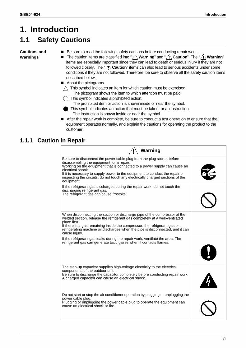
1.1.1 Caution in Repair
Warning
Be sure to disconnect the power cable plug from the plug socket before disassembling the equipment for a repair.Working on the equipment that is connected to a power supply can cause an electrical shook.If it is necessary to supply power to the equipment to conduct the repair or inspecting the circuits, do not touch any electrically charged sections of the equipment.
If the refrigerant gas discharges during the repair work, do not touch the discharging refrigerant gas.The refrigerant gas can cause frostbite.
When disconnecting the suction or discharge pipe of the compressor at the welded section, release the refrigerant gas completely at a well-ventilated place first.If there is a gas remaining inside the compressor, the refrigerant gas or refrigerating machine oil discharges when the pipe is disconnected, and it can cause injury.
If the refrigerant gas leaks during the repair work, ventilate the area. The refrigerant gas can generate toxic gases when it contacts flames.
The step-up capacitor supplies high-voltage electricity to the electrical components of the outdoor unit.Be sure to discharge the capacitor completely before conducting repair work.A charged capacitor can cause an electrical shock.
Do not start or stop the air conditioner operation by plugging or unplugging the power cable plug.Plugging or unplugging the power cable plug to operate the equipment can cause an electrical shock or fire.
Introduction SiBE04-624
viii
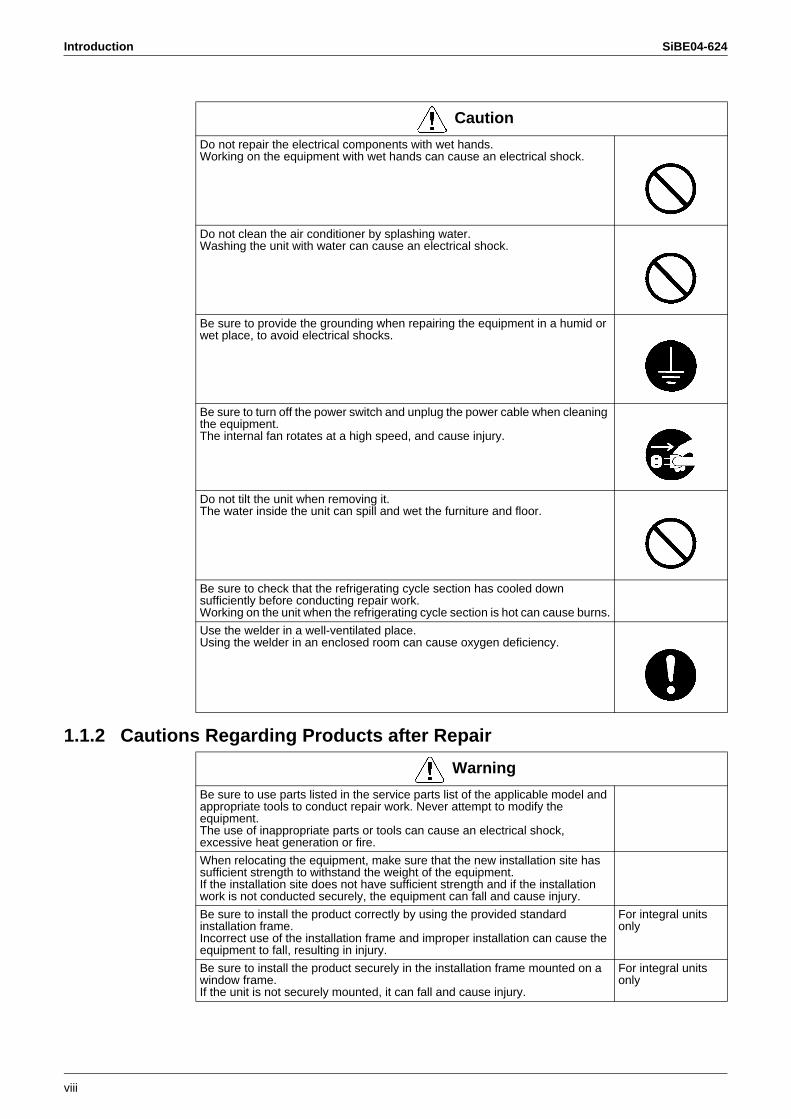
1.1.2 Cautions Regarding Products after Repair
Caution
Do not repair the electrical components with wet hands.Working on the equipment with wet hands can cause an electrical shock.
Do not clean the air conditioner by splashing water.Washing the unit with water can cause an electrical shock.
Be sure to provide the grounding when repairing the equipment in a humid or wet place, to avoid electrical shocks.
Be sure to turn off the power switch and unplug the power cable when cleaning the equipment.The internal fan rotates at a high speed, and cause injury.
Do not tilt the unit when removing it.The water inside the unit can spill and wet the furniture and floor.
Be sure to check that the refrigerating cycle section has cooled down sufficiently before conducting repair work.Working on the unit when the refrigerating cycle section is hot can cause burns.
Use the welder in a well-ventilated place.Using the welder in an enclosed room can cause oxygen deficiency.
Warning
Be sure to use parts listed in the service parts list of the applicable model and appropriate tools to conduct repair work. Never attempt to modify the equipment. The use of inappropriate parts or tools can cause an electrical shock, excessive heat generation or fire.
When relocating the equipment, make sure that the new installation site has sufficient strength to withstand the weight of the equipment.If the installation site does not have sufficient strength and if the installation work is not conducted securely, the equipment can fall and cause injury.
Be sure to install the product correctly by using the provided standard installation frame.Incorrect use of the installation frame and improper installation can cause the equipment to fall, resulting in injury.
For integral units only
Be sure to install the product securely in the installation frame mounted on a window frame.If the unit is not securely mounted, it can fall and cause injury.
For integral units only
SiBE04-624 Introduction
ix
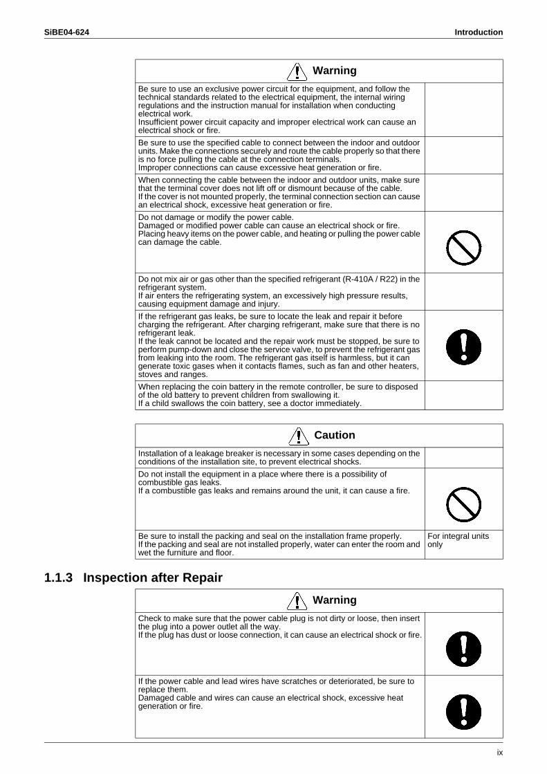
1.1.3 Inspection after Repair
Be sure to use an exclusive power circuit for the equipment, and follow the technical standards related to the electrical equipment, the internal wiring regulations and the instruction manual for installation when conducting electrical work.Insufficient power circuit capacity and improper electrical work can cause an electrical shock or fire.
Be sure to use the specified cable to connect between the indoor and outdoor units. Make the connections securely and route the cable properly so that there is no force pulling the cable at the connection terminals.Improper connections can cause excessive heat generation or fire.
When connecting the cable between the indoor and outdoor units, make sure that the terminal cover does not lift off or dismount because of the cable.If the cover is not mounted properly, the terminal connection section can cause an electrical shock, excessive heat generation or fire.
Do not damage or modify the power cable.Damaged or modified power cable can cause an electrical shock or fire.Placing heavy items on the power cable, and heating or pulling the power cable can damage the cable.
Do not mix air or gas other than the specified refrigerant (R-410A / R22) in the refrigerant system.If air enters the refrigerating system, an excessively high pressure results, causing equipment damage and injury.
If the refrigerant gas leaks, be sure to locate the leak and repair it before charging the refrigerant. After charging refrigerant, make sure that there is no refrigerant leak. If the leak cannot be located and the repair work must be stopped, be sure to perform pump-down and close the service valve, to prevent the refrigerant gas from leaking into the room. The refrigerant gas itself is harmless, but it can generate toxic gases when it contacts flames, such as fan and other heaters, stoves and ranges.
When replacing the coin battery in the remote controller, be sure to disposed of the old battery to prevent children from swallowing it.If a child swallows the coin battery, see a doctor immediately.
Warning
Caution
Installation of a leakage breaker is necessary in some cases depending on the conditions of the installation site, to prevent electrical shocks.
Do not install the equipment in a place where there is a possibility of combustible gas leaks.If a combustible gas leaks and remains around the unit, it can cause a fire.
Be sure to install the packing and seal on the installation frame properly.If the packing and seal are not installed properly, water can enter the room and wet the furniture and floor.
For integral units only
Warning
Check to make sure that the power cable plug is not dirty or loose, then insert the plug into a power outlet all the way.If the plug has dust or loose connection, it can cause an electrical shock or fire.
If the power cable and lead wires have scratches or deteriorated, be sure to replace them.Damaged cable and wires can cause an electrical shock, excessive heat generation or fire.
Introduction SiBE04-624
x
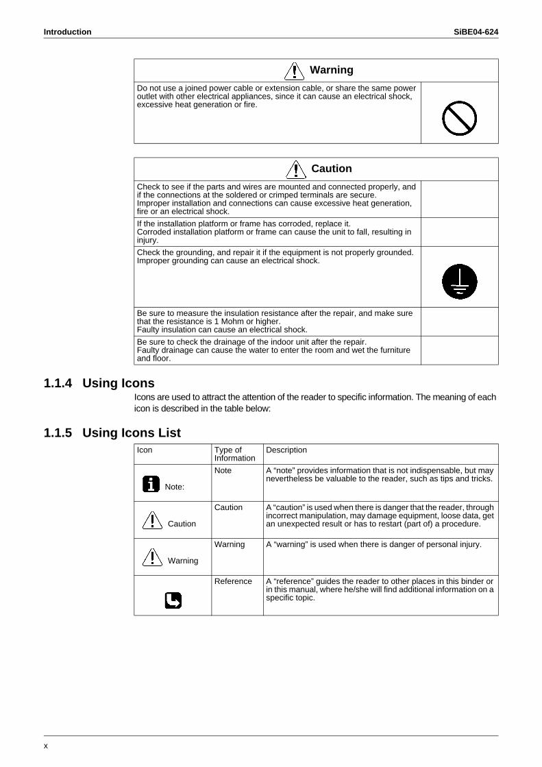
1.1.4 Using IconsIcons are used to attract the attention of the reader to specific information. The meaning of each icon is described in the table below:
1.1.5 Using Icons List
Do not use a joined power cable or extension cable, or share the same power outlet with other electrical appliances, since it can cause an electrical shock, excessive heat generation or fire.
Warning
Caution
Check to see if the parts and wires are mounted and connected properly, and if the connections at the soldered or crimped terminals are secure.Improper installation and connections can cause excessive heat generation, fire or an electrical shock.
If the installation platform or frame has corroded, replace it.Corroded installation platform or frame can cause the unit to fall, resulting in injury.
Check the grounding, and repair it if the equipment is not properly grounded.Improper grounding can cause an electrical shock.
Be sure to measure the insulation resistance after the repair, and make sure that the resistance is 1 Mohm or higher.Faulty insulation can cause an electrical shock.
Be sure to check the drainage of the indoor unit after the repair.Faulty drainage can cause the water to enter the room and wet the furniture and floor.
Icon Type of Information
Description
Note:
Note A “note” provides information that is not indispensable, but may nevertheless be valuable to the reader, such as tips and tricks.
Caution
Caution A “caution” is used when there is danger that the reader, through incorrect manipulation, may damage equipment, loose data, get an unexpected result or has to restart (part of) a procedure.
Warning
Warning A “warning” is used when there is danger of personal injury.
Reference A “reference” guides the reader to other places in this binder or in this manual, where he/she will find additional information on a specific topic.
SiBE04-624
List of Functions 1
Part 1List of Functions
1. Functions.................................................................................................2
Functions SiBE04-624
2 List of Functions
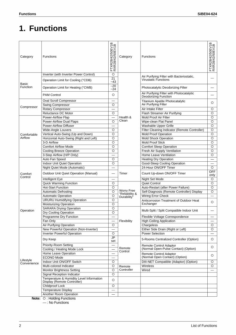
1. Functions
Category Functions
FT
XR
28/4
2/50
EV
1BR
XR
28/4
2/50
EV
1B
Category Functions
FT
XR
28/4
2/50
EV
1BR
XR
28/4
2/50
EV
1B
Basic Function
Inverter (with Inverter Power Control)
Health & Clean
Air Purifying Filter with Bacteriostatic, Virustatic Functions —
Operation Limit for Cooling (°CDB) 21~43
Operation Limit for Heating (°CWB) –20~24 Photocatalytic Deodorizing Filter —
PAM Control Air Purifying Filter with Photocatalytic Deodorizing Function —
Compressor
Oval Scroll Compressor — Titanium Apatite Photocatalytic Air Purifying FilterSwing Compressor
Rotary Compressor — Air Intake FilterReluctance DC Motor Flash Streamer Air Purifying
Comfortable Airflow
Power-Airflow Flap — Mold Proof Air FilterPower-Airflow Dual Flaps Wipe-clean Flat PanelPower-Airflow Diffuser — Washable Upper GrilleWide-Angle Louvers Filter Cleaning Indicator (Remote Controller)Vertical Auto-Swing (Up and Down) Mold Proof OperationHorizontal Auto-Swing (Right and Left) Mold Shock Operation3-D Airflow Mold Proof StickComfort Airflow Mode Comfort Sleep OperationCooling Breeze Operation Fresh Air Supply Ventilation3-Step Airflow (H/P Only) — Home Leave Ventilation
Comfort Control
Auto Fan Speed Heating Dry Operation —Indoor Unit Quiet Operation Good-Sleep Cooling Operation —Night Quiet Mode (Automatic) —
Timer
24-Hour ON/OFF Timer
Outdoor Unit Quiet Operation (Manual) — Count Up-down ON/OFF Timer OFF only
Intelligent Eye — Night Set ModeQuick Warming Function
Worry Free “Reliability & Durability”
Quiet ControlHot-Start Function Auto-Restart (after Power Failure)Automatic Defrosting Self-Diagnosis (Remote Controller) Display
Operation
Automatic Operation Wiring Error Check —URURU Humidifying Operation Anticorrosion Treatment of Outdoor Heat
ExchangerMoisturizing OperationSARARA Drying Operation
Flexibility
Multi-Split / Split Compatible Indoor Unit —Dry Cooling OperationProgramme Dry Function — Flexible Voltage Correspondence —Fan Only — High Ceiling Application —Air Purifying Operation Chargeless
Lifestyle Convenience
New Powerful Operation (Non-Inverter) — Either Side Drain (Right or Left)Inverter Powerful Operation Power Selection —
Dry Keep JPset
Remote Control
5-Rooms Centralized Controller (Option)
Priority-Room Setting — Remote Control Adaptor(Normal Open-Pulse Contact) (Option)Cooling / Heating Mode Lock —
Home Leave Operation — Remote Control Adaptor (Normal Open Contact) (Option)ECONO Mode —
Indoor Unit ON/OFF Switch DIII-NET Compatible (Adaptor) (Option)Multi-colored Indicator Remote
ControllerWireless
Monitor Brightness Setting Wired —Signal Reception IndicatorTemperature & Humidity Level Information Display (Remote Controller)Childproof LockTemperature Display —Another Room Operation —
Note: : Holding Functions— : No Functions
SiBE04-624
Specifications 3
Part 2Specifications
1. Specifications ..........................................................................................4
Specifications SiBE04-624
4 Room Air Conditioners E-Series
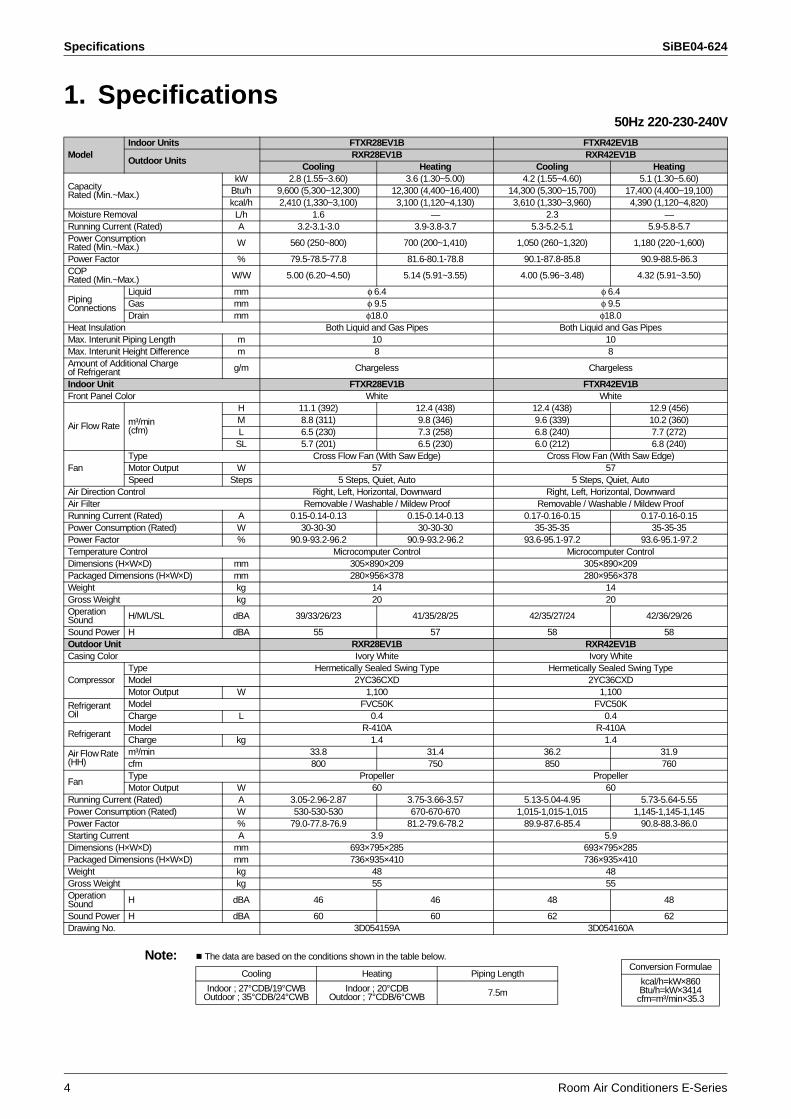
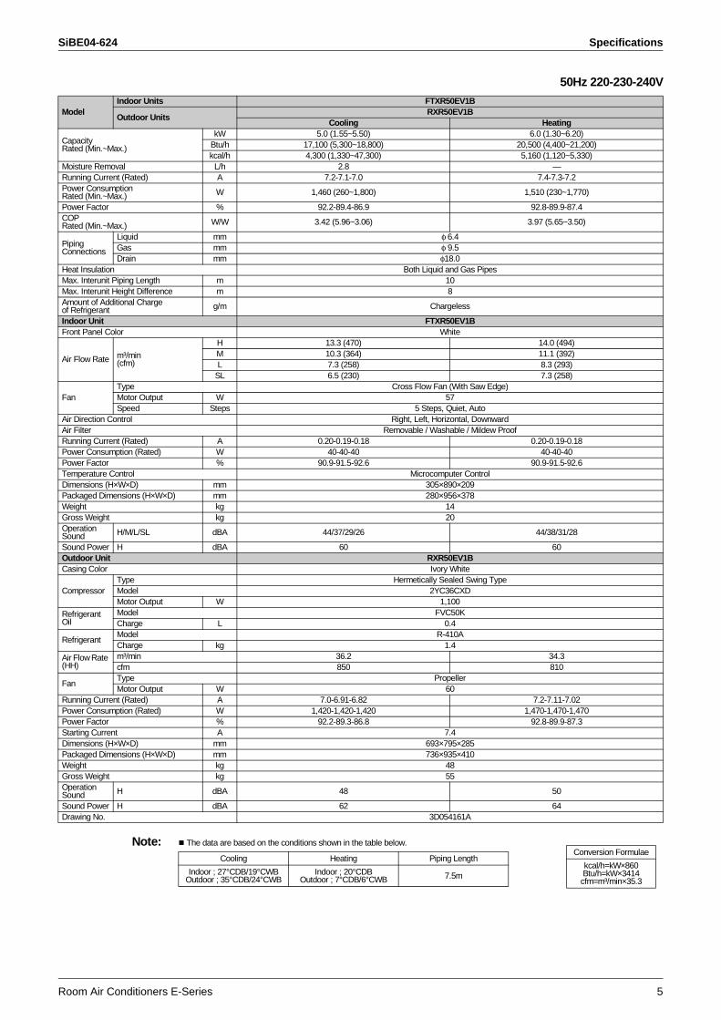
1. Specifications50Hz 220-230-240V
Note: The data are based on the conditions shown in the table below.
ModelIndoor Units FTXR28EV1B FTXR42EV1B
Outdoor UnitsRXR28EV1B RXR42EV1B
Cooling Heating Cooling Heating
Capacity Rated (Min.~Max.)
kW 2.8 (1.55~3.60) 3.6 (1.30~5.00) 4.2 (1.55~4.60) 5.1 (1.30~5.60)Btu/h 9,600 (5,300~12,300) 12,300 (4,400~16,400) 14,300 (5,300~15,700) 17,400 (4,400~19,100)kcal/h 2,410 (1,330~3,100) 3,100 (1,120~4,130) 3,610 (1,330~3,960) 4,390 (1,120~4,820)
Moisture Removal L/h 1.6 — 2.3 —Running Current (Rated) A 3.2-3.1-3.0 3.9-3.8-3.7 5.3-5.2-5.1 5.9-5.8-5.7Power Consumption Rated (Min.~Max.) W 560 (250~800) 700 (200~1,410) 1,050 (260~1,320) 1,180 (220~1,600)
Power Factor % 79.5-78.5-77.8 81.6-80.1-78.8 90.1-87.8-85.8 90.9-88.5-86.3COP Rated (Min.~Max.) W/W 5.00 (6.20~4.50) 5.14 (5.91~3.55) 4.00 (5.96~3.48) 4.32 (5.91~3.50)
Piping Connections
Liquid mm φ 6.4 φ 6.4Gas mm φ 9.5 φ 9.5Drain mm φ18.0 φ18.0
Heat Insulation Both Liquid and Gas Pipes Both Liquid and Gas PipesMax. Interunit Piping Length m 10 10Max. Interunit Height Difference m 8 8Amount of Additional Charge of Refrigerant g/m Chargeless Chargeless
Indoor Unit FTXR28EV1B FTXR42EV1BFront Panel Color White White
Air Flow Rate m³/min (cfm)
H 11.1 (392) 12.4 (438) 12.4 (438) 12.9 (456)M 8.8 (311) 9.8 (346) 9.6 (339) 10.2 (360)L 6.5 (230) 7.3 (258) 6.8 (240) 7.7 (272)
SL 5.7 (201) 6.5 (230) 6.0 (212) 6.8 (240)
FanType Cross Flow Fan (With Saw Edge) Cross Flow Fan (With Saw Edge)Motor Output W 57 57Speed Steps 5 Steps, Quiet, Auto 5 Steps, Quiet, Auto
Air Direction Control Right, Left, Horizontal, Downward Right, Left, Horizontal, DownwardAir Filter Removable / Washable / Mildew Proof Removable / Washable / Mildew ProofRunning Current (Rated) A 0.15-0.14-0.13 0.15-0.14-0.13 0.17-0.16-0.15 0.17-0.16-0.15Power Consumption (Rated) W 30-30-30 30-30-30 35-35-35 35-35-35Power Factor % 90.9-93.2-96.2 90.9-93.2-96.2 93.6-95.1-97.2 93.6-95.1-97.2Temperature Control Microcomputer Control Microcomputer ControlDimensions (H×W×D) mm 305×890×209 305×890×209Packaged Dimensions (H×W×D) mm 280×956×378 280×956×378Weight kg 14 14Gross Weight kg 20 20Operation Sound H/M/L/SL dBA 39/33/26/23 41/35/28/25 42/35/27/24 42/36/29/26
Sound Power H dBA 55 57 58 58Outdoor Unit RXR28EV1B RXR42EV1BCasing Color Ivory White Ivory White
CompressorType Hermetically Sealed Swing Type Hermetically Sealed Swing TypeModel 2YC36CXD 2YC36CXDMotor Output W 1,100 1,100
Refrigerant Oil
Model FVC50K FVC50KCharge L 0.4 0.4
RefrigerantModel R-410A R-410ACharge kg 1.4 1.4
Air Flow Rate (HH)
m³/min 33.8 31.4 36.2 31.9cfm 800 750 850 760
FanType Propeller PropellerMotor Output W 60 60
Running Current (Rated) A 3.05-2.96-2.87 3.75-3.66-3.57 5.13-5.04-4.95 5.73-5.64-5.55Power Consumption (Rated) W 530-530-530 670-670-670 1,015-1,015-1,015 1,145-1,145-1,145Power Factor % 79.0-77.8-76.9 81.2-79.6-78.2 89.9-87.6-85.4 90.8-88.3-86.0Starting Current A 3.9 5.9Dimensions (H×W×D) mm 693×795×285 693×795×285Packaged Dimensions (H×W×D) mm 736×935×410 736×935×410Weight kg 48 48Gross Weight kg 55 55Operation Sound H dBA 46 46 48 48
Sound Power H dBA 60 60 62 62Drawing No. 3D054159A 3D054160A
Conversion Formulae
kcal/h=kW×860Btu/h=kW×3414
cfm=m³/min×35.3
Cooling Heating Piping Length
Indoor ; 27°CDB/19°CWB Outdoor ; 35°CDB/24°CWB
Indoor ; 20°CDBOutdoor ; 7°CDB/6°CWB 7.5m
SiBE04-624 Specifications
Room Air Conditioners E-Series 5
50Hz 220-230-240V
Note: The data are based on the conditions shown in the table below.
ModelIndoor Units FTXR50EV1B
Outdoor UnitsRXR50EV1B
Cooling Heating
Capacity Rated (Min.~Max.)
kW 5.0 (1.55~5.50) 6.0 (1.30~6.20)Btu/h 17,100 (5,300~18,800) 20,500 (4,400~21,200)kcal/h 4,300 (1,330~47,300) 5,160 (1,120~5,330)
Moisture Removal L/h 2.8 —Running Current (Rated) A 7.2-7.1-7.0 7.4-7.3-7.2Power Consumption Rated (Min.~Max.) W 1,460 (260~1,800) 1,510 (230~1,770)
Power Factor % 92.2-89.4-86.9 92.8-89.9-87.4COP Rated (Min.~Max.) W/W 3.42 (5.96~3.06) 3.97 (5.65~3.50)
Piping Connections
Liquid mm φ 6.4Gas mm φ 9.5Drain mm φ18.0
Heat Insulation Both Liquid and Gas PipesMax. Interunit Piping Length m 10Max. Interunit Height Difference m 8Amount of Additional Charge of Refrigerant g/m Chargeless
Indoor Unit FTXR50EV1BFront Panel Color White
Air Flow Rate m³/min (cfm)
H 13.3 (470) 14.0 (494)M 10.3 (364) 11.1 (392)L 7.3 (258) 8.3 (293)
SL 6.5 (230) 7.3 (258)
FanType Cross Flow Fan (With Saw Edge)Motor Output W 57Speed Steps 5 Steps, Quiet, Auto
Air Direction Control Right, Left, Horizontal, DownwardAir Filter Removable / Washable / Mildew ProofRunning Current (Rated) A 0.20-0.19-0.18 0.20-0.19-0.18Power Consumption (Rated) W 40-40-40 40-40-40Power Factor % 90.9-91.5-92.6 90.9-91.5-92.6Temperature Control Microcomputer ControlDimensions (H×W×D) mm 305×890×209Packaged Dimensions (H×W×D) mm 280×956×378Weight kg 14Gross Weight kg 20Operation Sound H/M/L/SL dBA 44/37/29/26 44/38/31/28
Sound Power H dBA 60 60Outdoor Unit RXR50EV1BCasing Color Ivory White
CompressorType Hermetically Sealed Swing TypeModel 2YC36CXDMotor Output W 1,100
Refrigerant Oil
Model FVC50KCharge L 0.4
RefrigerantModel R-410ACharge kg 1.4
Air Flow Rate (HH)
m³/min 36.2 34.3cfm 850 810
FanType PropellerMotor Output W 60
Running Current (Rated) A 7.0-6.91-6.82 7.2-7.11-7.02Power Consumption (Rated) W 1,420-1,420-1,420 1,470-1,470-1,470Power Factor % 92.2-89.3-86.8 92.8-89.9-87.3Starting Current A 7.4Dimensions (H×W×D) mm 693×795×285Packaged Dimensions (H×W×D) mm 736×935×410Weight kg 48Gross Weight kg 55Operation Sound H dBA 48 50
Sound Power H dBA 62 64Drawing No. 3D054161A
Conversion Formulae
kcal/h=kW×860Btu/h=kW×3414
cfm=m³/min×35.3
Cooling Heating Piping Length
Indoor ; 27°CDB/19°CWB Outdoor ; 35°CDB/24°CWB
Indoor ; 20°CDBOutdoor ; 7°CDB/6°CWB 7.5m
Specifications SiBE04-624
6 Room Air Conditioners E-Series
SiBE04-624
Printed Circuit Board Connector Wiring Diagram 7
Part 3Printed Circuit Board
Connector Wiring Diagram
1. Printed Circuit Board Connector Wiring Diagram....................................81.1 Indoor Unit................................................................................................81.2 Outdoor Unit ...........................................................................................10
Printed Circuit Board Connector Wiring Diagram SiBE04-624
8 Printed Circuit Board Connector Wiring Diagram
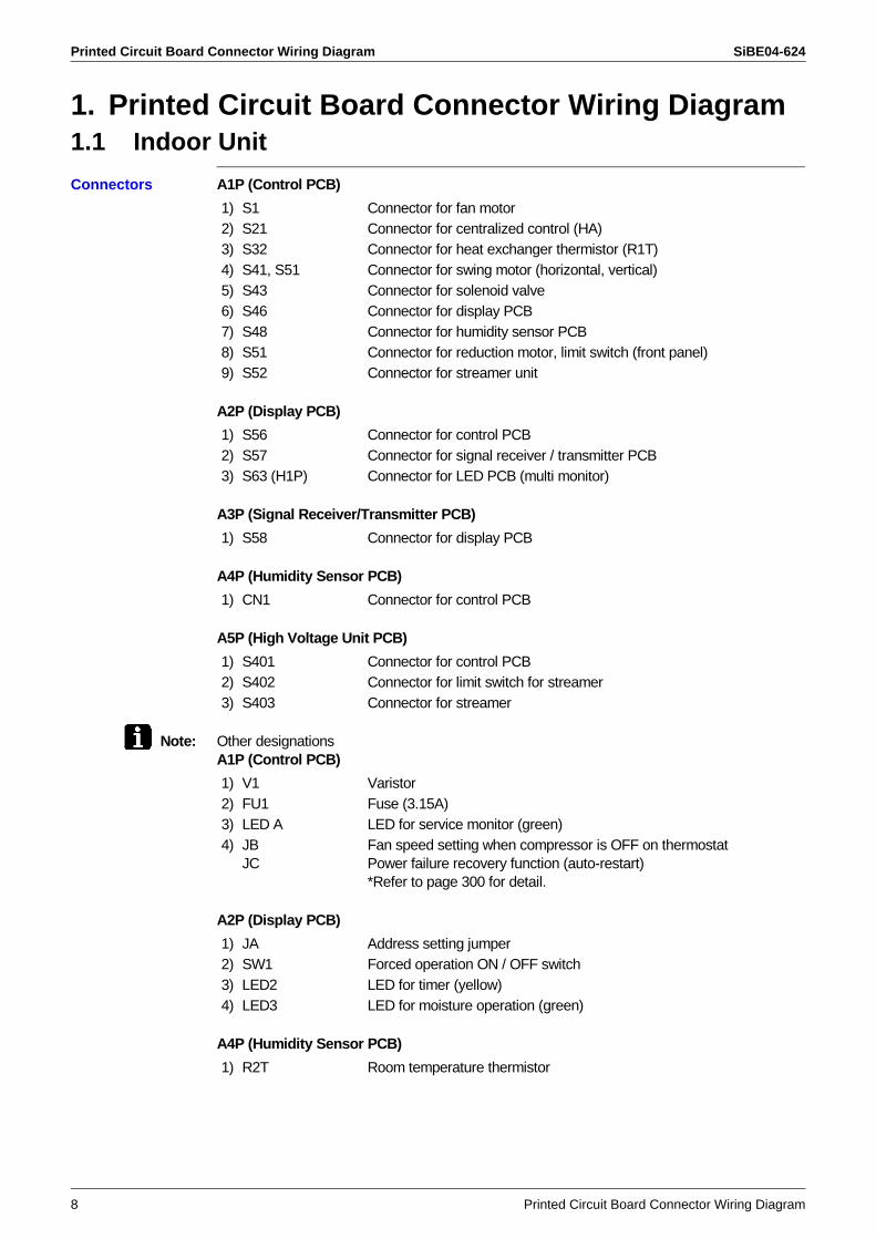
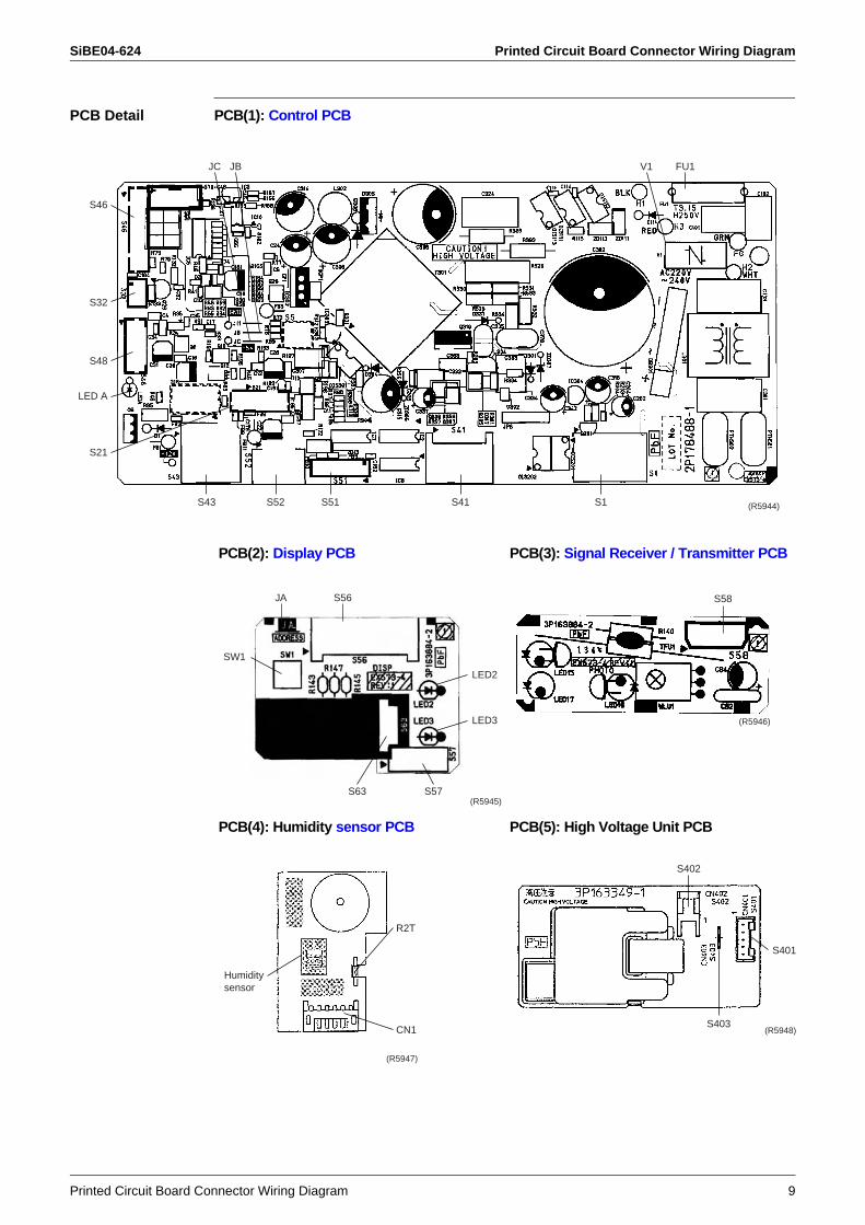
1. Printed Circuit Board Connector Wiring Diagram1.1 Indoor Unit
Connectors A1P (Control PCB)
A2P (Display PCB)
A3P (Signal Receiver/Transmitter PCB)
A4P (Humidity Sensor PCB)
A5P (High Voltage Unit PCB)
Note: Other designationsA1P (Control PCB)
A2P (Display PCB)
A4P (Humidity Sensor PCB)
1) S1 Connector for fan motor2) S21 Connector for centralized control (HA)3) S32 Connector for heat exchanger thermistor (R1T)4) S41, S51 Connector for swing motor (horizontal, vertical)5) S43 Connector for solenoid valve6) S46 Connector for display PCB7) S48 Connector for humidity sensor PCB8) S51 Connector for reduction motor, limit switch (front panel)9) S52 Connector for streamer unit
1) S56 Connector for control PCB2) S57 Connector for signal receiver / transmitter PCB3) S63 (H1P) Connector for LED PCB (multi monitor)
1) S58 Connector for display PCB
1) CN1 Connector for control PCB
1) S401 Connector for control PCB2) S402 Connector for limit switch for streamer3) S403 Connector for streamer
1) V1 Varistor2) FU1 Fuse (3.15A)3) LED A LED for service monitor (green)4) JB
JCFan speed setting when compressor is OFF on thermostatPower failure recovery function (auto-restart)*Refer to page 300 for detail.
1) JA Address setting jumper2) SW1 Forced operation ON / OFF switch3) LED2 LED for timer (yellow)4) LED3 LED for moisture operation (green)
1) R2T Room temperature thermistor
SiBE04-624 Printed Circuit Board Connector Wiring Diagram
Printed Circuit Board Connector Wiring Diagram 9
PCB Detail PCB(1): Control PCB
FU1V1JBJC
S32
S48
S21
S43
LED A
S46
S52 S41 S1S51 (R5944)
PCB(2): Display PCB PCB(3): Signal Receiver / Transmitter PCB
PCB(4): Humidity sensor PCB PCB(5): High Voltage Unit PCB
JA S56
SW1
LED2
LED3
S57S63(R5945)
S58
(R5946)
R2T
CN1
Humidity sensor
(R5947)
S403
S401
S402
(R5948)
Printed Circuit Board Connector Wiring Diagram SiBE04-624
10 Printed Circuit Board Connector Wiring Diagram
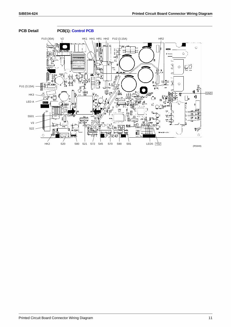
1.2 Outdoor Unit
Connectors
Note: Other designations
1) S20 Connector for electronic expansion valve coil2) S21 Connector for rotor motor3) S22 Connector for damper motor4) S45 Connector for thermal fuse5) S70 Connector for DC fan motor6) S72 Connector for humidification fan motor7) S80 Connector for four way valve coil8) S90 Connector for thermistor (outdoor, heat exchanger,
discharge pipe)9) S91 Connector for humidifying thermistor10)S501 Connector for limit switch11)HR1, HR2 Connector for reactor12)HK1, HK2, HK3 Connector for fan motor13)HH1, HH2 Connector for heater
1) FU1, FU2 Fuse (3.15A)2) FU3 Fuse (30A)3) V2, V3 Varistor4) LED A, LED5 LED for service monitor (green)
SiBE04-624 Printed Circuit Board Connector Wiring Diagram
Printed Circuit Board Connector Wiring Diagram 11
PCB Detail PCB(1): Control PCB
HR2FU2 (3.15A)HH2HH1HK1V2FU3 (30A) HR1
FU1 (3.15A)
HK3
LED A
S501
S22
HK2 S20 S80 S21 S72 S45 S70
V3
S90 S91 LED5 +5V(R5949)
GND
Printed Circuit Board Connector Wiring Diagram SiBE04-624
12 Printed Circuit Board Connector Wiring Diagram
SiBE04-624
Function and Control 13
Part 4Function and Control
1. Description of Operation .......................................................................151.1 Indoor Unit..............................................................................................151.2 Outdoor Unit ...........................................................................................16
2. Main Functions......................................................................................172.1 “URURU” Humidifying / Humid Heating Operation.................................172.2 “SARARA” Drying Operation ..................................................................262.3 Comfort Sleep Operation........................................................................282.4 MOISTURIZING Operation ....................................................................302.5 Automatic Operation...............................................................................312.6 Comfort Airflow Mode.............................................................................322.7 Cooling Breeze Operation ......................................................................342.8 Power-airflow Dual Flaps .......................................................................352.9 Wide-angle Louvers ...............................................................................362.10 3-D Airflow..............................................................................................372.11 POWERFUL Operation ..........................................................................382.12 Indoor Unit Quiet Operation ...................................................................392.13 Multi-colored Indicator Lamp ..................................................................392.14 Monitor Brightness Setting .....................................................................402.15 Information Display.................................................................................402.16 MOLD PROOF Operation ......................................................................412.17 Mold Proof Stick .....................................................................................432.18 MOLD SHOCK Operation ......................................................................442.19 HOME LEAVE Ventilation ......................................................................472.20 FLASH STREAMER AIR PURIFYING Operation ..................................482.21 Fresh Air Supply Ventilation ...................................................................512.22 Wipe-clean Flat Panel ............................................................................532.23 Filter Cleaning Indicator (Remote Controller).........................................532.24 TIMER Operation ...................................................................................542.25 Night Set Mode.......................................................................................552.26 Table for Special Modes.........................................................................562.27 Thermostat Control.................................................................................582.28 Fan Speed Control for Indoor Units........................................................592.29 Draft Prevention (HOT Start)..................................................................61
3. Control Specification .............................................................................623.1 Frequency Control..................................................................................623.2 Preheating Operation (Quick Warming Function) ..................................633.3 Four-way Valve Operation......................................................................643.4 Compressor Start up Protection .............................................................653.5 Fan Speed Control for Outdoor Unit.......................................................663.6 Fin Thermistor Control............................................................................663.7 Input Current Control..............................................................................673.8 Peak-cut Control.....................................................................................683.9 Indoor Coil Freeze up Protection............................................................693.10 Dew Prevention ......................................................................................703.11 Liquid Compression Protection 2 ...........................................................71
SiBE04-624
14 Function and Control
3.12 Discharge Pipe Temperature Control.....................................................723.13 Automatic Defrosting ..............................................................................733.14 Electronic Expansion Valve Control .......................................................75
SiBE04-624 Description of Operation
Function and Control 15
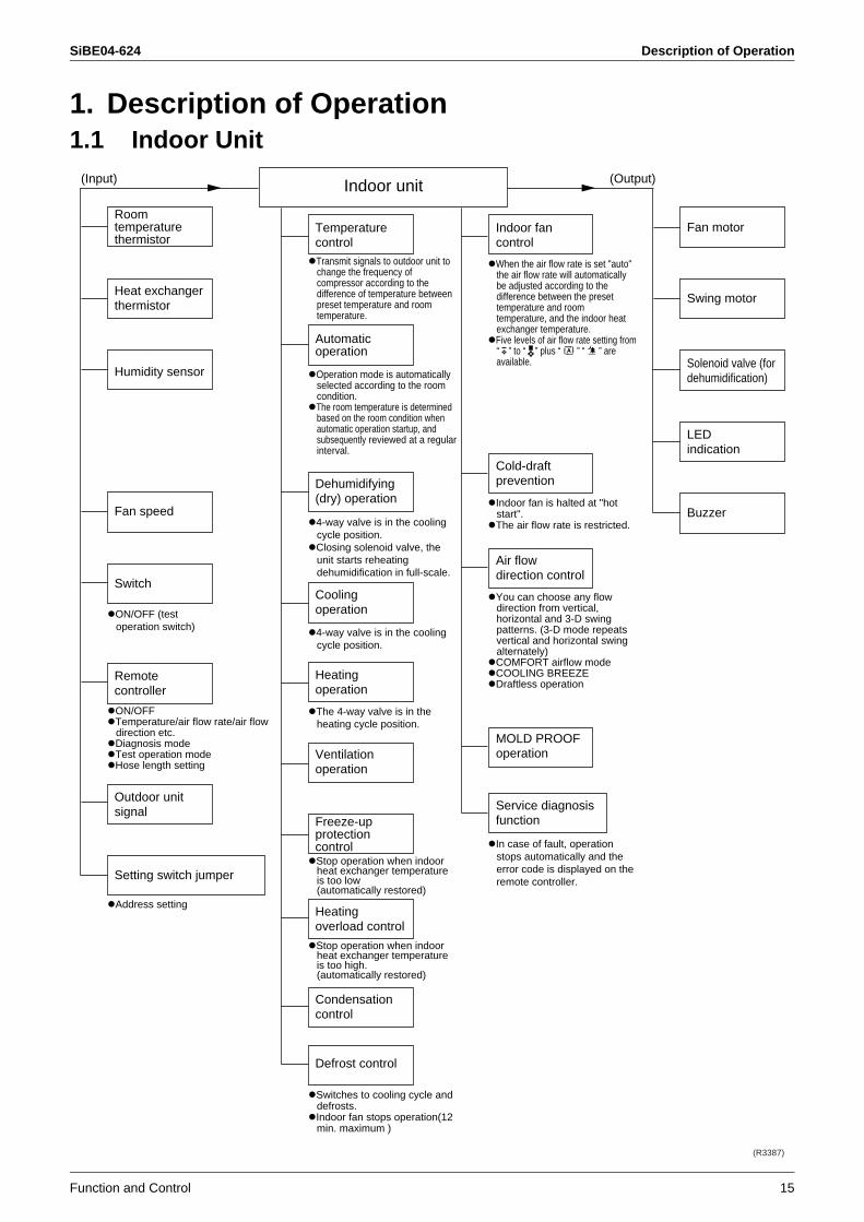
1. Description of Operation1.1 Indoor Unit
(Input) (Output)
Room temperature thermistor
Temperature control
Indoor fan control
Fan motor
Swing motor
LED indication
Buzzer
Solenoid valve (for dehumidification)
Cold-draft prevention
Air flow direction control
MOLD PROOF operation
Service diagnosis function
Automatic operation
Dehumidifying (dry) operation
Cooling operation
Heating operation
Ventilation operation
Freeze-up protection control
Heating overload control
Condensation control
Defrost control
Indoor unit
Heat exchanger thermistor
Humidity sensor
Fan speed
Switch
ON/OFF (test operation switch)
Transmit signals to outdoor unit to change the frequency of compressor according to the difference of temperature between preset temperature and room temperature.
When the air flow rate is set "auto" the air flow rate will automatically be adjusted according to the difference between the preset temperature and room temperature, and the indoor heat exchanger temperature.Five levels of air flow rate setting from “ ” to “ ” plus “ ” “ ” are available.
Indoor fan is halted at "hot start".The air flow rate is restricted.
You can choose any flow direction from vertical, horizontal and 3-D swing patterns. (3-D mode repeats vertical and horizontal swing alternately)COMFORT airflow modeCOOLING BREEZEDraftless operation
In case of fault, operation stops automatically and the error code is displayed on the remote controller.
Operation mode is automatically selected according to the room condition.The room temperature is determined based on the room condition when automatic operation startup, and subsequently reviewed at a regular interval.
4-way valve is in the cooling cycle position.Closing solenoid valve, the unit starts reheating dehumidification in full-scale.
4-way valve is in the cooling cycle position.
The 4-way valve is in the heating cycle position.
Stop operation when indoor heat exchanger temperature is too low(automatically restored)
Stop operation when indoor heat exchanger temperature is too high.(automatically restored)
Switches to cooling cycle and defrosts.Indoor fan stops operation(12 min. maximum )
Remote controller
Setting switch jumper
Outdoor unit signal
ON/OFFTemperature/air flow rate/air flow direction etc.Diagnosis modeTest operation modeHose length setting
Address setting
(R3387)
Description of Operation SiBE04-624
16 Function and Control
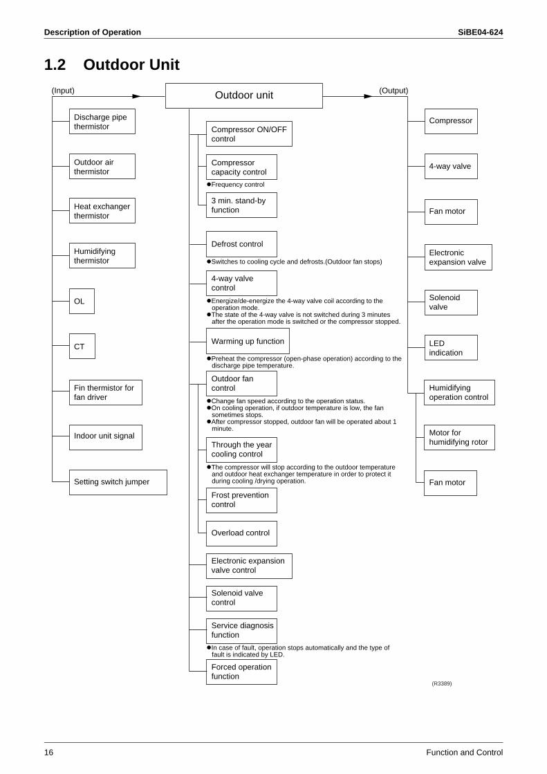
1.2 Outdoor Unit
(Input) (Output)
Compressor ON/OFF control
Compressor
4-way valve
Fan motor
Electronic expansion valve
Solenoid valve
LED indication
Humidifying operation control
Motor for humidifying rotor
Fan motor
Compressor capacity control
3 min. stand-by function
Defrost control
4-way valve control
Warming up function
Outdoor fan control
Through the year cooling control
Frost prevention control
Overload control
Electronic expansion valve control
Solenoid valve control
Service diagnosis function
Forced operation function
Outdoor air thermistor
Discharge pipe thermistor
Heat exchanger thermistor
Humidifying thermistor
Fin thermistor for fan driver
Indoor unit signal
Setting switch jumper
OL
Outdoor unit
Frequency control
Switches to cooling cycle and defrosts.(Outdoor fan stops)
Energize/de-energize the 4-way valve coil according to the operation mode.The state of the 4-way valve is not switched during 3 minutes after the operation mode is switched or the compressor stopped.
Preheat the compressor (open-phase operation) according to the discharge pipe temperature.
Change fan speed according to the operation status.On cooling operation, if outdoor temperature is low, the fan sometimes stops.After compressor stopped, outdoor fan will be operated about 1 minute.
The compressor will stop according to the outdoor temperature and outdoor heat exchanger temperature in order to protect it during cooling /drying operation.
In case of fault, operation stops automatically and the type of fault is indicated by LED.
CT
(R3389)
SiBE04-624 Main Functions
Function and Control 17
2. Main Functions2.1 “URURU” Humidifying / Humid Heating Operation
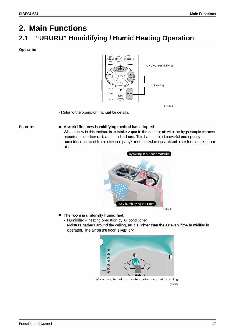
Operation
∗ Refer to the operation manual for details.
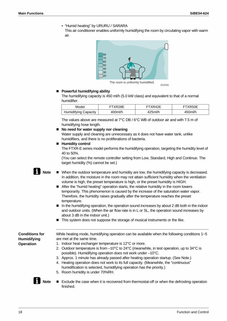
Features A world first new humidifying method has adoptedWhat is new in this method is to intake vapor in the outdoor air with the hygroscopic element mounted in outdoor unit, and send indoors. This has enabled powerful and speedy humidification apart from other company's methods which just absorb moisture in the indoor air.
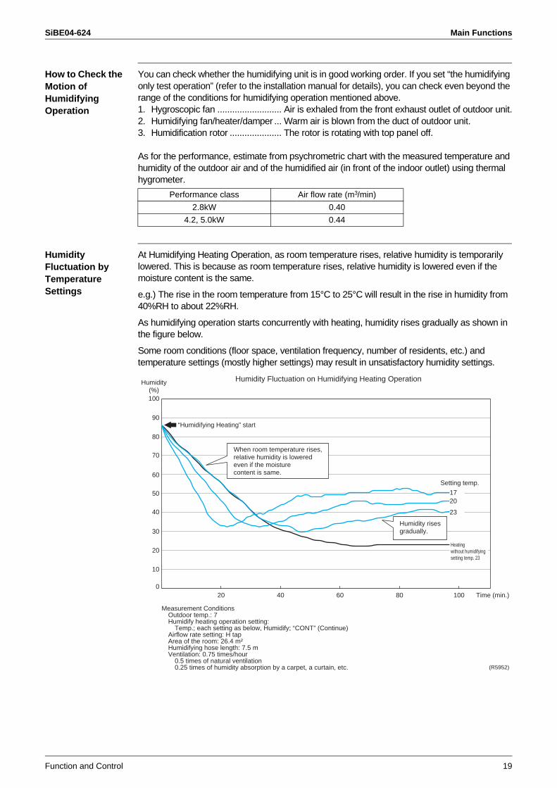
The room is uniformly humidified.• Humidifier + heating operation by air conditioner
Moisture gathers around the ceiling, as it is lighter than the air even if the humidifier is operated. The air on the floor is kept dry.
"URURU" Humidifying
Humid Heating
(R5951)
by taking in outdoor moisture
fully humidifying the room
(R3324)
When using humidifier, moisture gathers around the ceiling.
80706050403020
(R3325)
Main Functions SiBE04-624
18 Function and Control
• “Humid heating” by URURU / SARARAThis air conditioner enables uniformly humidifying the room by circulating vapor with warm air.
Powerful humidifying abilityThe humidifying capacity is 450 ml/h (5.0 kW class) and equivalent to that of a normal humidifier.
The values above are measured at 7°C DB / 6°C WB of outdoor air and with 7.5 m of humidifying hose length.No need for water supply nor cleaningWater supply and cleaning are unnecessary as it does not have water tank, unlike humidifiers, and there is no proliferations of bacteria.Humidity controlThe FTXR-E series model performs the humidifying operation, targeting the humidity level of 40 to 50%.(You can select the remote controller setting from Low, Standard, High and Continue. The target humidity (%) cannot be set.)
Note When the outdoor temperature and humidity are low, the humidifying capacity is decreased. In addition, the moisture in the room may not attain sufficient humidity when the ventilation volume is high, the preset temperature is high, or the preset humidity is HIGH.After the “humid heating” operation starts, the relative humidity in the room lowers temporarily. This phenomenon is caused by the increase of the saturation water vapor. Therefore, the humidity raises gradually after the temperature reaches the preset temperature.In the humidifying operation, the operation sound increases by about 2 dB both in the indoor and outdoor units. (When the air flow rate is in L or SL, the operation sound increases by about 3 dB in the indoor unit.)This system does not suppose the storage of musical instruments or the like.
Conditions for Humidifying Operation
While heating mode, humidifying operation can be available when the following conditions 1~5 are met at the same time.1. Indoor heat exchanger temperature is 12°C or more.2. Outdoor temperature is from –10°C to 24°C (meanwhile, in test operation, up to 34°C is
possible). Humidifying operation does not work under –10°C.3. Approx. 1 minute has already passed after heating operation startup. (See Note.)4. Heating operation does not work to its full capacity. (Meanwhile, the “continuous”
humidification is selected, humidifying operation has the priority.)5. Room humidity is under 70%RH.
Note Exclude the case when it is recovered from thermostat-off or when the defrosting operation finished.
Model FTXR28E FTXR42E FTXR50E
Humidifying Capacity 400ml/h 425ml/h 450ml/h
80706050403020
(R3326)The room is uniformly humidified.
SiBE04-624 Main Functions
Function and Control 19
How to Check the Motion of Humidifying Operation
You can check whether the humidifying unit is in good working order. If you set “the humidifying only test operation” (refer to the installation manual for details), you can check even beyond the range of the conditions for humidifying operation mentioned above.1. Hygroscopic fan .......................... Air is exhaled from the front exhaust outlet of outdoor unit.2. Humidifying fan/heater/damper ... Warm air is blown from the duct of outdoor unit.3. Humidification rotor ..................... The rotor is rotating with top panel off.
As for the performance, estimate from psychrometric chart with the measured temperature and humidity of the outdoor air and of the humidified air (in front of the indoor outlet) using thermal hygrometer.
Humidity Fluctuation by Temperature Settings
At Humidifying Heating Operation, as room temperature rises, relative humidity is temporarily lowered. This is because as room temperature rises, relative humidity is lowered even if the moisture content is the same.
e.g.) The rise in the room temperature from 15°C to 25°C will result in the rise in humidity from 40%RH to about 22%RH.
As humidifying operation starts concurrently with heating, humidity rises gradually as shown in the figure below.
Some room conditions (floor space, ventilation frequency, number of residents, etc.) and temperature settings (mostly higher settings) may result in unsatisfactory humidity settings.
Performance class Air flow rate (m3/min)
2.8kW 0.40
4.2, 5.0kW 0.44
90
100
Humidity(%)
80
70
60
50
40
30
20
10
020 40 60 80 100 Time (min.)
17
Setting temp.
“Humidifying Heating” start
20
23
Heatingwithout humidifyingsetting temp. 23
Humidity Fluctuation on Humidifying Heating Operation
When room temperature rises,relative humidity is loweredeven if the moisturecontent is same.
Humidity risesgradually.
(R5952)
Measurement ConditionsOutdoor temp.: 7Humidify heating operation setting:
Temp.; each setting as below, Humidify; “CONT” (Continue)Airflow rate setting: H tapArea of the room: 26.4 m²Humidifying hose length: 7.5 mVentilation: 0.75 times/hour
0.5 times of natural ventilation0.25 times of humidity absorption by a carpet, a curtain, etc.
Main Functions SiBE04-624
20 Function and Control
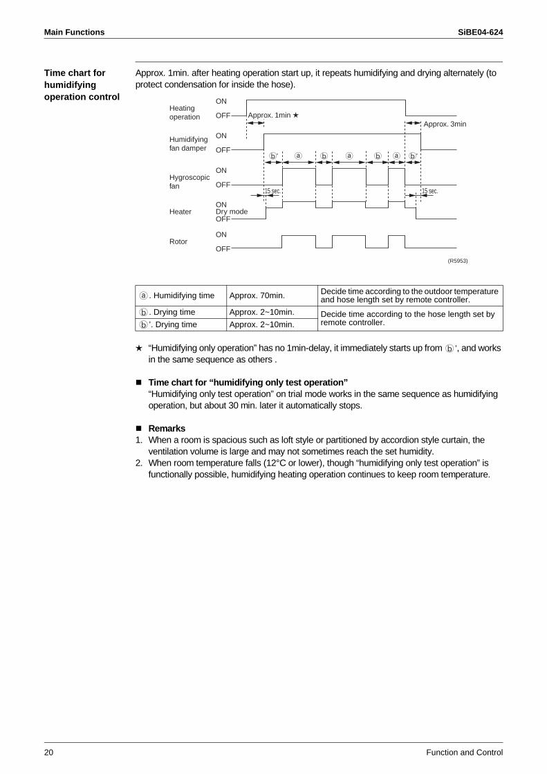
Time chart for humidifying operation control
Approx. 1min. after heating operation start up, it repeats humidifying and drying alternately (to protect condensation for inside the hose).
“Humidifying only operation” has no 1min-delay, it immediately starts up from ’, and works in the same sequence as others .
Time chart for “humidifying only test operation”“Humidifying only test operation” on trial mode works in the same sequence as humidifying operation, but about 30 min. later it automatically stops.
Remarks1. When a room is spacious such as loft style or partitioned by accordion style curtain, the
ventilation volume is large and may not sometimes reach the set humidity.2. When room temperature falls (12°C or lower), though “humidifying only test operation” is
functionally possible, humidifying heating operation continues to keep room temperature.
. Humidifying time Approx. 70min. Decide time according to the outdoor temperature and hose length set by remote controller.
. Drying time Approx. 2~10min. Decide time according to the hose length set by remote controller.’. Drying time Approx. 2~10min.
Heatingoperation
ON
OFF
Humidifyingfan damper
ON
OFF
Hygroscopicfan
ON
OFF
HeaterON
OFF
RotorON
OFF
Approx. 1min Approx. 3min
15 sec. 15 sec.
Dry mode
b' b'a a ab b
(R5953)
SiBE04-624 Main Functions
Function and Control 21
Humidification performance by outdoor temperature
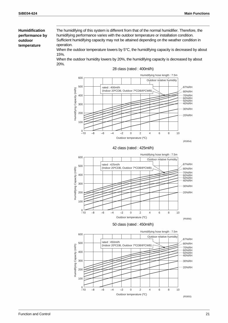
The humidifying of this system is different from that of the normal humidifier. Therefore, the humidifying performance varies with the outdoor temperature or installation condition.Sufficient humidifying capacity may not be attained depending on the weather condition in operation.When the outdoor temperature lowers by 5°C, the humidifying capacity is decreased by about 15%.When the outdoor humidity lowers by 20%, the humidifying capacity is decreased by about 20%.
28 class (rated : 400ml/h)
42 class (rated : 425ml/h)
50 class (rated : 450ml/h)
00 2 4 6 8 10
100
200
300
400
500
600H
umid
ifyin
g C
apac
ity (
ml/h
)
Outdoor temperature (ºC)
Humidifying hose length : 7.5m
Outdoor relative humidity
87%RH
80%RH
70%RH60%RH50%RH40%RH
30%RH
20%RH
rated : 400ml/h(Indoor 20ºCDB, Outdoor 7ºCDB/6ºCWB)
(R5954)
00 2 4 6 8 10
100
200
300
400
500
600
Hum
idify
ing
Cap
acity
(m
l/h)
Outdoor temperature (ºC)
Humidifying hose length : 7.5m
Outdoor relative humidity
87%RH
80%RH
70%RH60%RH50%RH40%RH
30%RH
20%RH
rated : 425ml/h(Indoor 20ºCDB, Outdoor 7ºCDB/6ºCWB)
(R5956)
00 2 4 6 8 10
100
200
300
400
500
600
Hum
idify
ing
Cap
acity
(m
l/h)
Outdoor temperature (ºC)
Humidifying hose length : 7.5m
87%RH
80%RH
70%RH60%RH50%RH40%RH
30%RH
20%RH
Outdoor relative humidity
rated : 450ml/h(Indoor 20ºCDB, Outdoor 7ºCDB/6ºCWB)
(R5955)
Main Functions SiBE04-624
22 Function and Control
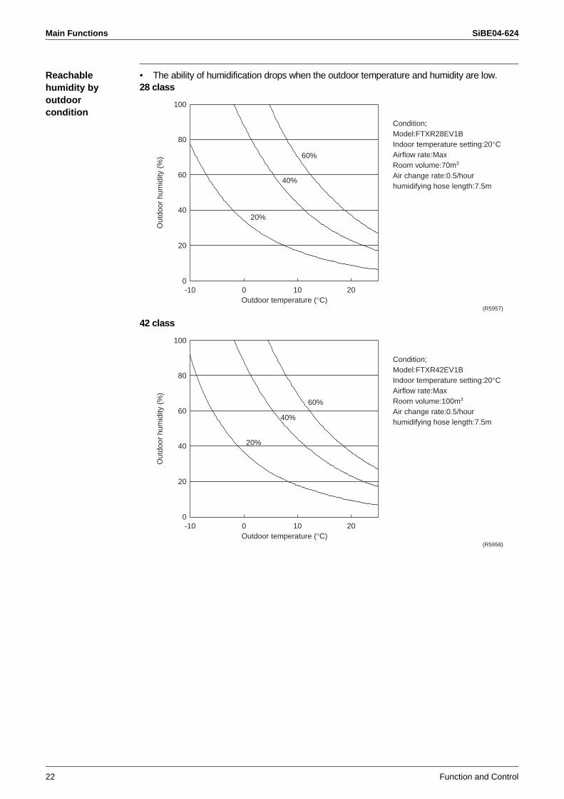
Reachable humidity by outdoor condition
• The ability of humidification drops when the outdoor temperature and humidity are low.28 class
42 class
100
80
60
40
20
0-10 0 10 20
20%
40%
60%O
utdo
or h
umid
ity (
%)
Outdoor temperature (°C)(R5957)
Condition;Model:FTXR28EV1BIndoor temperature setting:20°CAirflow rate:MaxRoom volume:70m3
Air change rate:0.5/hourhumidifying hose length:7.5m
100
80
60
40
20
0-10 0 10 20
20%
40%
60%
Out
door
hum
idity
(%
)
Outdoor temperature (°C)(R5958)
Condition;Model:FTXR42EV1BIndoor temperature setting:20°CAirflow rate:MaxRoom volume:100m3
Air change rate:0.5/hourhumidifying hose length:7.5m
SiBE04-624 Main Functions
Function and Control 23
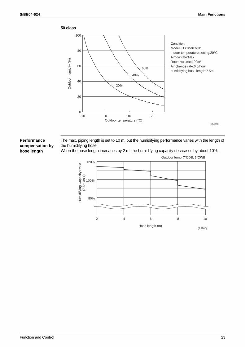
50 class
Performance compensation by hose length
The max. piping length is set to 10 m, but the humidifying performance varies with the length of the humidifying hose. When the hose length increases by 2 m, the humidifying capacity decreases by about 10%.
100
80
60
40
20
0-10 0 10 20
20%
40%
60%O
utdo
or h
umid
ity (
%)
Outdoor temperature (°C)(R5959)
Condition;Model:FTXR50EV1BIndoor temperature setting:20°CAirflow rate:MaxRoom volume:120m3
Air change rate:0.5/hourhumidifying hose length:7.5m
2 4 6 8 10
80%
100%
120%
Hose length (m)
Hum
idify
ing
Cap
acity
Rat
io(7
.5m
as
1)
(R5960)
Main Functions SiBE04-624
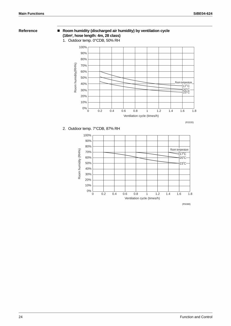
24 Function and Control
Reference Room humidity (discharged air humidity) by ventilation cycle (16m2, hose length: 4m, 28 class)1. Outdoor temp. 0°CDB, 50% RH
2. Outdoor temp. 7°CDB, 87% RH
(R3335)
100%
90%
80%
70%
60%
50%
40%
30%
20%
10%
0%
Ventilation cycle (times/h)
17˚C20˚C23˚C
0 0.2 0.4 0.6 0.8 1 1.2 1.4 1.6 1.8
Roo
m h
umid
ity(R
H%
)
Room temperature
100%
0%
10%
20%
30%
40%
50%
60%
70%
80%
90%
0 0.2 0.4 0.6 0.8 1.2 1.4 1.61 1.8
Room temperature17˚C20˚C
23˚C
Ventilation cycle (times/h)
Roo
m h
umid
ity (
RH
%)
(R5088)
SiBE04-624 Main Functions
Function and Control 25
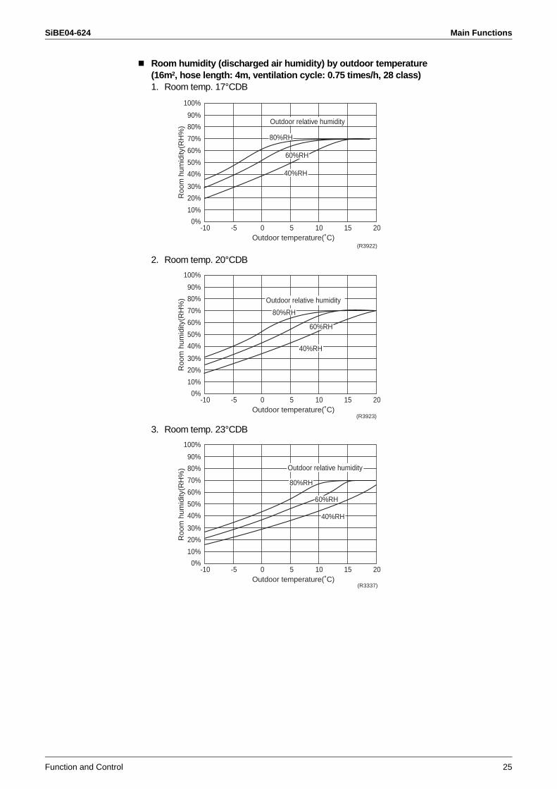
Room humidity (discharged air humidity) by outdoor temperature (16m2, hose length: 4m, ventilation cycle: 0.75 times/h, 28 class)1. Room temp. 17°CDB
2. Room temp. 20°CDB
3. Room temp. 23°CDB
0%-10 -5 0 5 10 15 20
10%
20%
30%
40%
50%
60%
70%
80%
90%
100%
Roo
m h
umid
ity(R
H%
)
Outdoor temperature(˚C)
Outdoor relative humidity
80%RH
60%RH
40%RH
(R3922)
0%-10 -5 0 5 10 15 20
10%
20%
30%
40%
50%
60%
70%
80%
90%
100%
Roo
m h
umid
ity(R
H%
)
Outdoor temperature(˚C)
Outdoor relative humidity
80%RH
60%RH
40%RH
(R3923)
0%-10 -5 0 5 10 15 20
10%
20%
30%
40%
50%
60%
70%
80%
90%
100%
Roo
m h
umid
ity(R
H%
)
Outdoor temperature(˚C)
Outdoor relative humidity
80%RH
60%RH
40%RH
(R3337)
Main Functions SiBE04-624
26 Function and Control
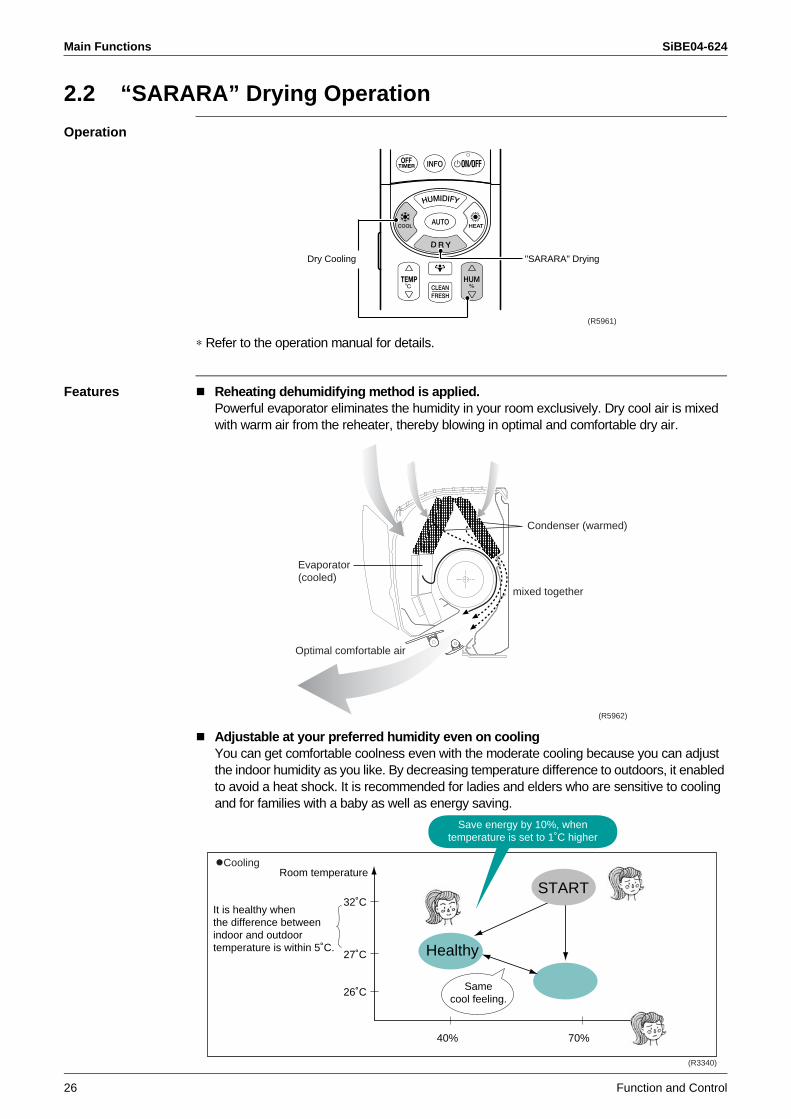
2.2 “SARARA” Drying Operation
Operation
∗ Refer to the operation manual for details.
Features Reheating dehumidifying method is applied.Powerful evaporator eliminates the humidity in your room exclusively. Dry cool air is mixed with warm air from the reheater, thereby blowing in optimal and comfortable dry air.
Adjustable at your preferred humidity even on coolingYou can get comfortable coolness even with the moderate cooling because you can adjust the indoor humidity as you like. By decreasing temperature difference to outdoors, it enabled to avoid a heat shock. It is recommended for ladies and elders who are sensitive to cooling and for families with a baby as well as energy saving.
"SARARA" DryingDry Cooling
(R5961)
Condenser (warmed)
mixed together
Evaporator(cooled)
Optimal comfortable air
(R5962)
32˚C
27˚C
26˚C
40% 70%
Room temperature
Healthy
START
Samecool feeling.
It is healthy whenthe difference between indoor and outdoor temperature is within 5˚C.
Cooling
Save energy by 10%, whentemperature is set to 1˚C higher
(R3340)
SiBE04-624 Main Functions
Function and Control 27
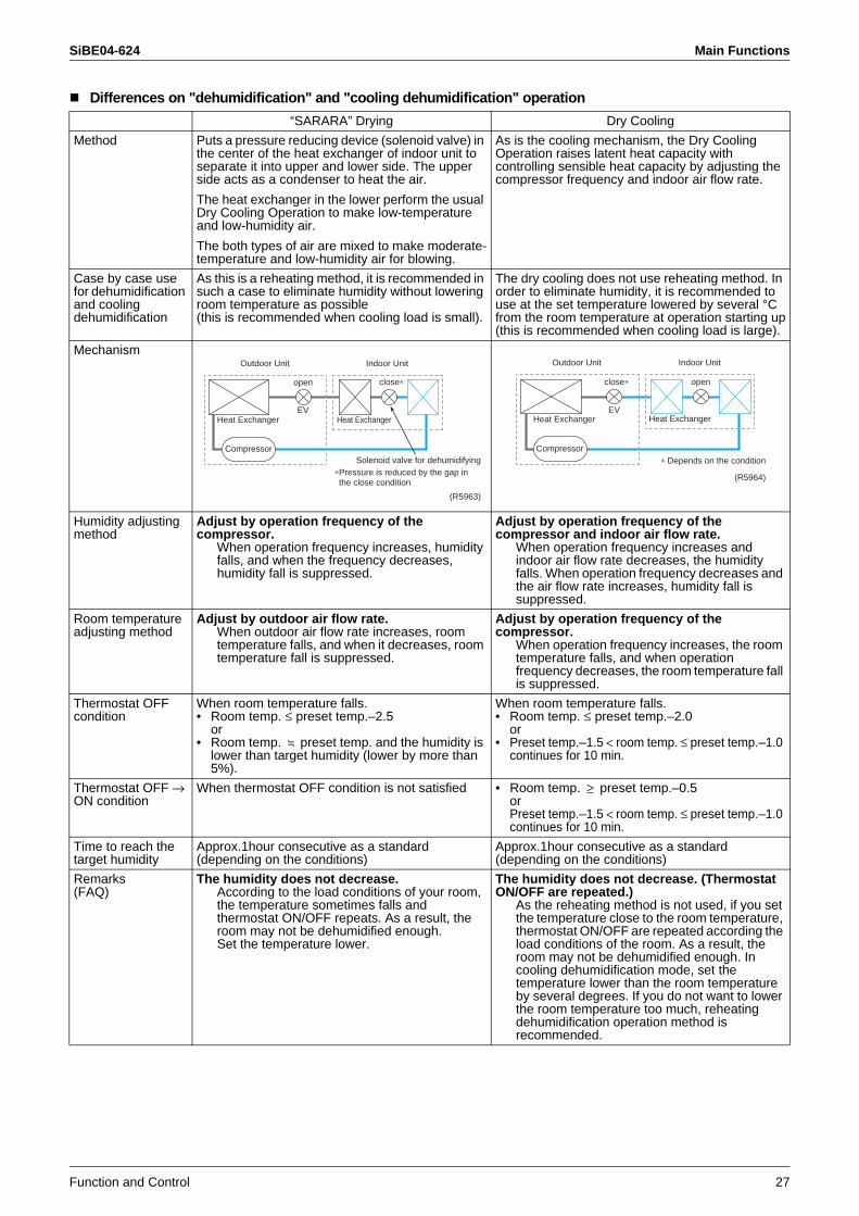
Differences on "dehumidification" and "cooling dehumidification" operation
“SARARA” Drying Dry Cooling
Method Puts a pressure reducing device (solenoid valve) in the center of the heat exchanger of indoor unit to separate it into upper and lower side. The upper side acts as a condenser to heat the air.
The heat exchanger in the lower perform the usual Dry Cooling Operation to make low-temperature and low-humidity air.
The both types of air are mixed to make moderate-temperature and low-humidity air for blowing.
As is the cooling mechanism, the Dry Cooling Operation raises latent heat capacity with controlling sensible heat capacity by adjusting the compressor frequency and indoor air flow rate.
Case by case use for dehumidification and cooling dehumidification
As this is a reheating method, it is recommended in such a case to eliminate humidity without lowering room temperature as possible(this is recommended when cooling load is small).
The dry cooling does not use reheating method. In order to eliminate humidity, it is recommended to use at the set temperature lowered by several °C from the room temperature at operation starting up(this is recommended when cooling load is large).
Mechanism
Humidity adjusting method
Adjust by operation frequency of the compressor.
When operation frequency increases, humidity falls, and when the frequency decreases, humidity fall is suppressed.
Adjust by operation frequency of the compressor and indoor air flow rate.
When operation frequency increases and indoor air flow rate decreases, the humidity falls. When operation frequency decreases and the air flow rate increases, humidity fall is suppressed.
Room temperature adjusting method
Adjust by outdoor air flow rate.When outdoor air flow rate increases, room temperature falls, and when it decreases, room temperature fall is suppressed.
Adjust by operation frequency of the compressor.
When operation frequency increases, the room temperature falls, and when operation frequency decreases, the room temperature fall is suppressed.
Thermostat OFF condition
When room temperature falls.• Room temp. ≤ preset temp.–2.5
or• Room temp. preset temp. and the humidity is
lower than target humidity (lower by more than 5%).
When room temperature falls.• Room temp. ≤ preset temp.–2.0
or• Preset temp.–1.5 < room temp. ≤ preset temp.–1.0
continues for 10 min.
Thermostat OFF → ON condition
When thermostat OFF condition is not satisfied • Room temp. preset temp.–0.5orPreset temp.–1.5 < room temp. ≤ preset temp.–1.0 continues for 10 min.
Time to reach the target humidity
Approx.1hour consecutive as a standard (depending on the conditions)
Approx.1hour consecutive as a standard (depending on the conditions)
Remarks(FAQ)
The humidity does not decrease.According to the load conditions of your room, the temperature sometimes falls and thermostat ON/OFF repeats. As a result, the room may not be dehumidified enough.Set the temperature lower.
The humidity does not decrease. (Thermostat ON/OFF are repeated.)
As the reheating method is not used, if you set the temperature close to the room temperature, thermostat ON/OFF are repeated according the load conditions of the room. As a result, the room may not be dehumidified enough. In cooling dehumidification mode, set the temperature lower than the room temperature by several degrees. If you do not want to lower the room temperature too much, reheating dehumidification operation method is recommended.
∗Pressure is reduced by the gap in the close condition
Solenoid valve for dehumidifying
close∗open
Heat ExchangerEV
Heat Exchanger
Outdoor Unit Indoor Unit
Compressor
(R5963)
Outdoor Unit Indoor Unit
openclose∗
Compressor∗ Depends on the condition
Heat ExchangerEV
Heat Exchanger
(R5964)
Main Functions SiBE04-624
28 Function and Control
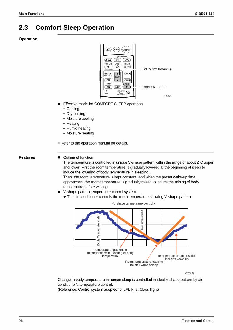
2.3 Comfort Sleep Operation
Operation
Effective mode for COMFORT SLEEP operation• Cooling• Dry cooling• Moisture cooling• Heating• Humid heating• Moisture heating
∗ Refer to the operation manual for details.
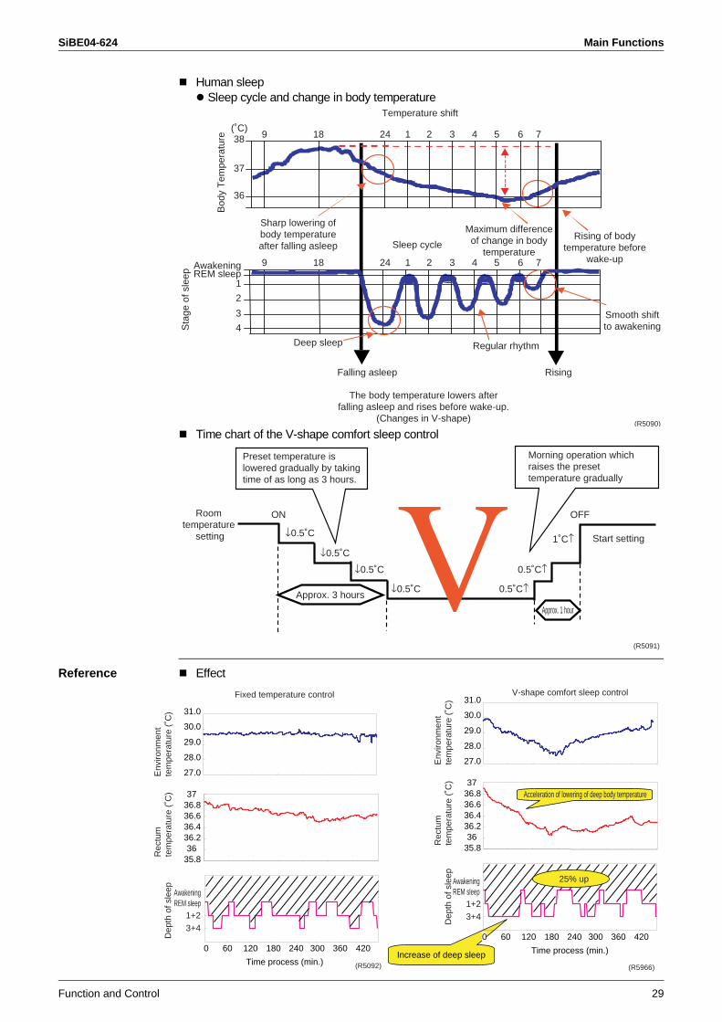
Features Outline of functionThe temperature is controlled in unique V-shape pattern within the range of about 2°C upper and lower. First the room temperature is gradually lowered at the beginning of sleep to induce the lowering of body temperature in sleeping.Then, the room temperature is kept constant, and when the preset wake-up time approaches, the room temperature is gradually raised to induce the raising of body temperature before waking.V-shape pattern temperature control system
The air conditioner controls the room temperature showing V-shape pattern.
Change in body temperature in human sleep is controlled in ideal V-shape pattern by air-conditioner’s temperature control.(Reference: Control system adopted for JAL First Class flight)
Set the time to wake up.
COMFORT SLEEP
(R5965)
<V shape temperature control>
Bod
y Te
mpe
ratu
re s
hift
Room
temp
eratur
e shif
t
Temperature gradient in accordance with lowering of body
temperature
Room temperature causing no chill while asleep
Temperature gradient which induces wake-up
(R5089)
SiBE04-624 Main Functions
Function and Control 29
Human sleep Sleep cycle and change in body temperature
Time chart of the V-shape comfort sleep control
Reference Effect
(˚C)38
37
36
Bod
y T
empe
ratu
re 9 18 24 1 2 3 4 5 6 7
9 18 24 1
1
2
3
4
2 3 4 5 6 7
Sleep cycle
Deep sleep Regular rhythm
Falling asleep Rising
Temperature shift
Sharp lowering of body temperature after falling asleep
Maximum difference of change in body
temperature
Rising of body temperature before
wake-up
Smooth shift to awakening
The body temperature lowers after falling asleep and rises before wake-up.
(Changes in V-shape)
AwakeningREM sleep
Sta
ge o
f sle
ep
(R5090)
Preset temperature is lowered gradually by taking time of as long as 3 hours.
Morning operation which raises the preset temperature gradually
Room temperature
setting
ON
Approx. 3 hours
Approx. 1 hour
Start setting
OFF
↓0.5˚C
↓0.5˚C1˚C↑
↓0.5˚C 0.5˚C↑
↓0.5˚C 0.5˚C↑
(R5091)
3736.836.636.436.2
35.836
0 60 120 180 240 300 360 420
Time process (min.)
27.0
28.0
29.0
30.0
31.0
Dep
th o
f sle
ep AwakeningREM sleep
1+2
3+4
Rec
tum
te
mpe
ratu
re (
˚C)
Env
ironm
ent
tem
pera
ture
(˚C
)
(R5092)
Fixed temperature control
Time process (min.)Increase of deep sleep
3736.836.636.436.2
35.836
27.0
28.0
29.0
30.0
31.0
Dep
th o
f sle
ep
AwakeningREM sleep
1+2
3+4
Rec
tum
te
mpe
ratu
re (
˚C)
Env
ironm
ent
tem
pera
ture
(˚C
)
0 60 120 180 240 300 360 420
25% up
Acceleration of lowering of deep body temperature
V-shape comfort sleep control
(R5966)
Main Functions SiBE04-624
30 Function and Control
2.4 MOISTURIZING Operation
Operation
Effective mode for MOISTURE COOLING• Cooling• Dry coolingEffective mode for MOISTURE HEATING• Heating• Humid heating
∗ Refer to the operation manual for details.
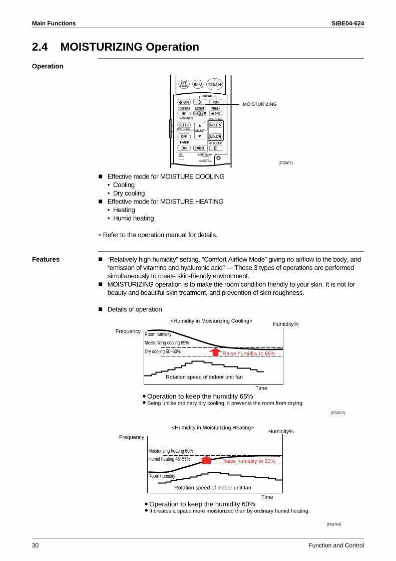
Features “Relatively high humidity” setting, “Comfort Airflow Mode” giving no airflow to the body, and “emission of vitamins and hyaluronic acid” --- These 3 types of operations are performed simultaneously to create skin-friendly environment.MOISTURIZING operation is to make the room condition friendly to your skin. It is not for beauty and beautiful skin treatment, and prevention of skin roughness.
Details of operation
MOISTURIZING
(R5967)
Frequency
Time
Moisturizing cooling 65%
Dry cooling 50~60%
Room humidity
Rotation speed of indoor unit fan
<Humidity in Moisturizing Cooling>
Raise humidity to 65%
Humidity%
Operation to keep the humidity 65% Being unlike ordinary dry cooling, it prevents the room from drying.
(R5093)
Frequency
Time
Moisturizing heating 60%
Humid heating 45~55%
Room humidity
Rotation speed of indoor unit fan
<Humidity in Moisturizing Heating>
Raise humidity to 60%
Humidity%
Operation to keep the humidity 60% It creates a space more moisturized than by ordinary humid heating.
(R5094)
SiBE04-624 Main Functions
Function and Control 31
2.5 Automatic Operation
Operation
∗ Refer to the operation manual for details.
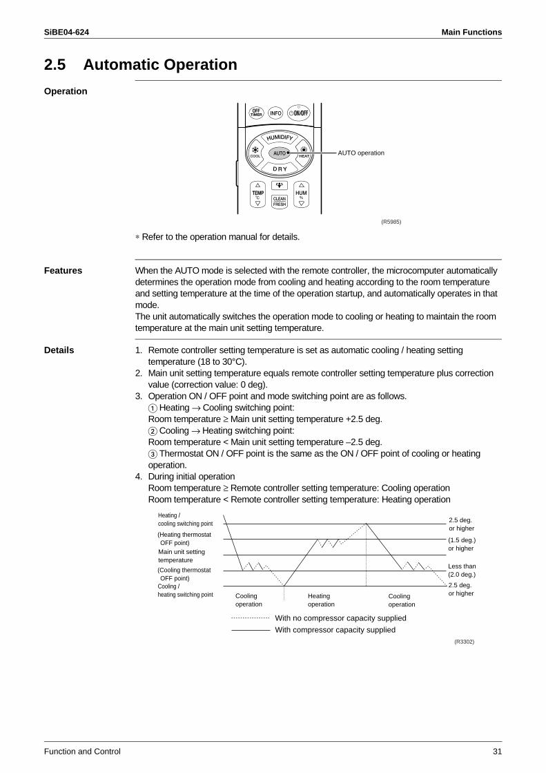
Features When the AUTO mode is selected with the remote controller, the microcomputer automatically determines the operation mode from cooling and heating according to the room temperature and setting temperature at the time of the operation startup, and automatically operates in that mode.The unit automatically switches the operation mode to cooling or heating to maintain the room temperature at the main unit setting temperature.
Details 1. Remote controller setting temperature is set as automatic cooling / heating setting temperature (18 to 30°C).
2. Main unit setting temperature equals remote controller setting temperature plus correction value (correction value: 0 deg).
3. Operation ON / OFF point and mode switching point are as follows. Heating → Cooling switching point: Room temperature ≥ Main unit setting temperature +2.5 deg. Cooling → Heating switching point: Room temperature < Main unit setting temperature –2.5 deg. Thermostat ON / OFF point is the same as the ON / OFF point of cooling or heating operation.
4. During initial operationRoom temperature ≥ Remote controller setting temperature: Cooling operationRoom temperature < Remote controller setting temperature: Heating operation
AUTO operation
(R5985)
Heating / cooling switching point 2.5 deg.
or higher(Heating thermostat OFF point)
Main unit settingtemperature
(Cooling thermostat OFF point)
Cooling /heating switching point Cooling
operationHeating operation
Cooling operation
With no compressor capacity supplied
With compressor capacity supplied
(1.5 deg.) or higher
Less than (2.0 deg.)
2.5 deg. or higher
(R3302)
Main Functions SiBE04-624
32 Function and Control
2.6 Comfort Airflow Mode
Operation
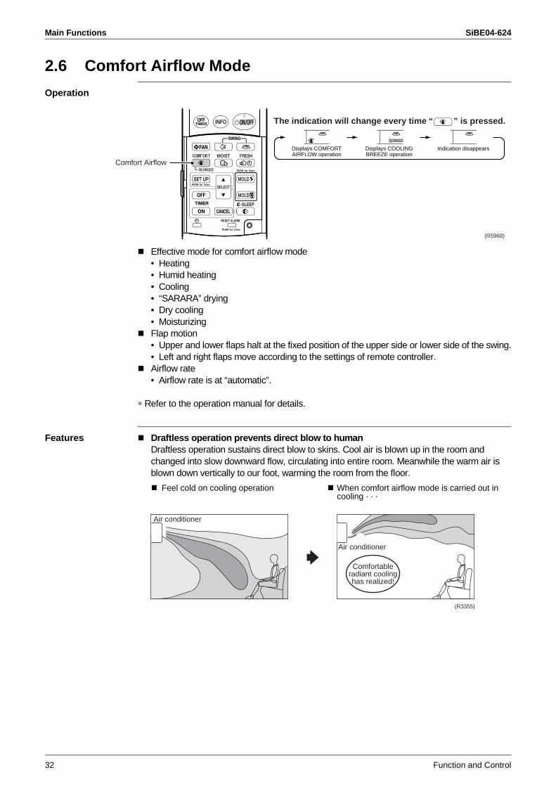
Effective mode for comfort airflow mode• Heating• Humid heating• Cooling• “SARARA” drying• Dry cooling• MoisturizingFlap motion• Upper and lower flaps halt at the fixed position of the upper side or lower side of the swing.• Left and right flaps move according to the settings of remote controller.Airflow rate• Airflow rate is at “automatic”.
∗ Refer to the operation manual for details.
Features Draftless operation prevents direct blow to humanDraftless operation sustains direct blow to skins. Cool air is blown up in the room and changed into slow downward flow, circulating into entire room. Meanwhile the warm air is blown down vertically to our foot, warming the room from the floor.
Comfort Airflow
The indication will change every time “ ” is pressed.
Displays COMFORTAIRFLOW operation
Displays COOLINGBREEZE operation
Indication disappears
(R5968)
Feel cold on cooling operation When comfort airflow mode is carried out in cooling · · ·
Comfortableradiant coolinghas realized!
(R3355)
Air conditioner
Air conditioner
SiBE04-624 Main Functions
Function and Control 33
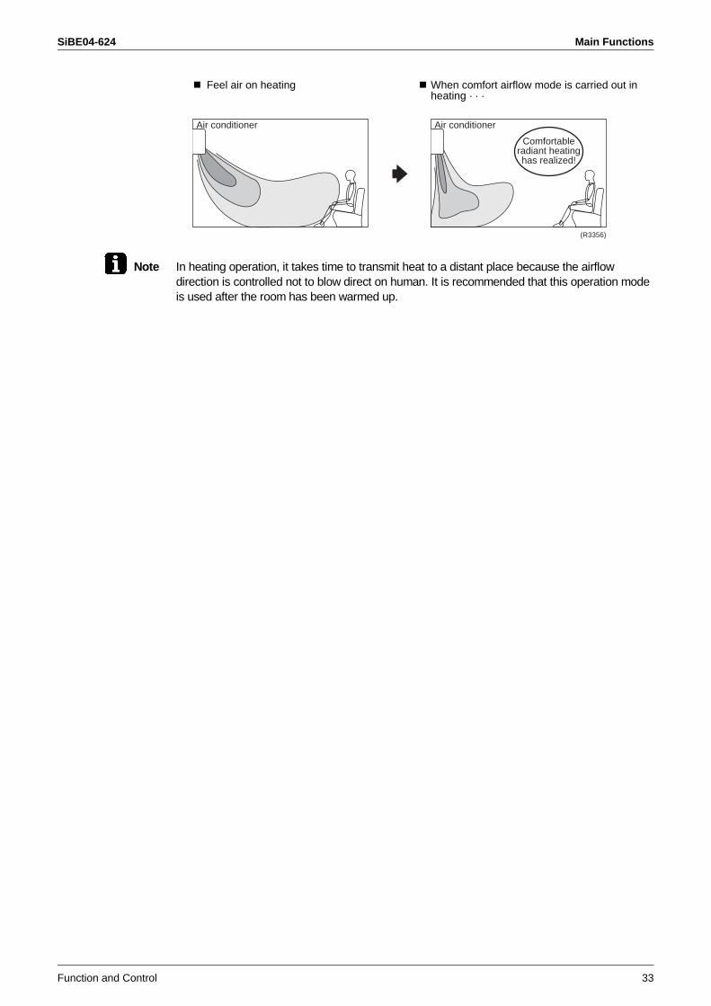
Note In heating operation, it takes time to transmit heat to a distant place because the airflow direction is controlled not to blow direct on human. It is recommended that this operation mode is used after the room has been warmed up.
Feel air on heating When comfort airflow mode is carried out in heating · · ·
Air conditioner
Comfortableradiant heatinghas realized!
(R3356)
Air conditioner
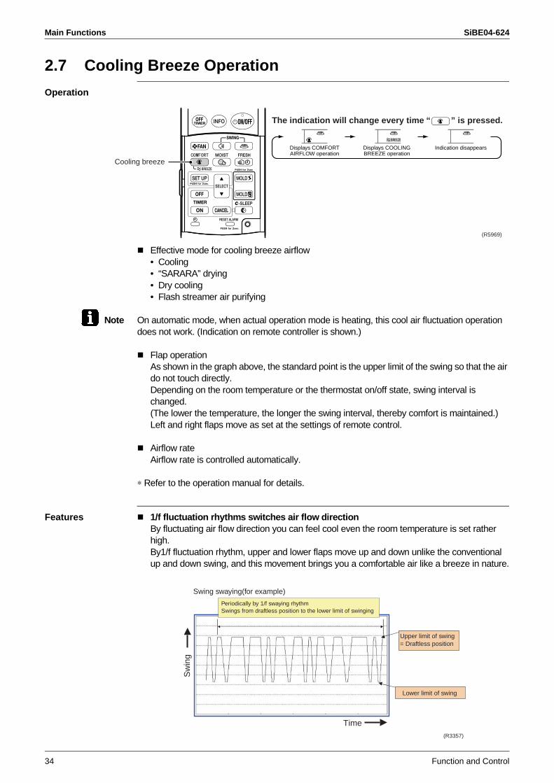
Main Functions SiBE04-624
34 Function and Control
2.7 Cooling Breeze Operation
Operation
Effective mode for cooling breeze airflow• Cooling• “SARARA” drying• Dry cooling• Flash streamer air purifying
Note On automatic mode, when actual operation mode is heating, this cool air fluctuation operation does not work. (Indication on remote controller is shown.)
Flap operationAs shown in the graph above, the standard point is the upper limit of the swing so that the air do not touch directly.Depending on the room temperature or the thermostat on/off state, swing interval is changed.(The lower the temperature, the longer the swing interval, thereby comfort is maintained.)Left and right flaps move as set at the settings of remote control.
Airflow rateAirflow rate is controlled automatically.
∗ Refer to the operation manual for details.
Features 1/f fluctuation rhythms switches air flow directionBy fluctuating air flow direction you can feel cool even the room temperature is set rather high. By1/f fluctuation rhythm, upper and lower flaps move up and down unlike the conventional up and down swing, and this movement brings you a comfortable air like a breeze in nature.
Cooling breeze
The indication will change every time “ ” is pressed.
Displays COMFORTAIRFLOW operation
Displays COOLINGBREEZE operation
Indication disappears
(R5969)
Sw
ing
Time
Upper limit of swing= Draftless position
Swing swaying(for example)
Periodically by 1/f swaying rhythmSwings from draftless position to the lower limit of swinging
Lower limit of swing
(R3357)
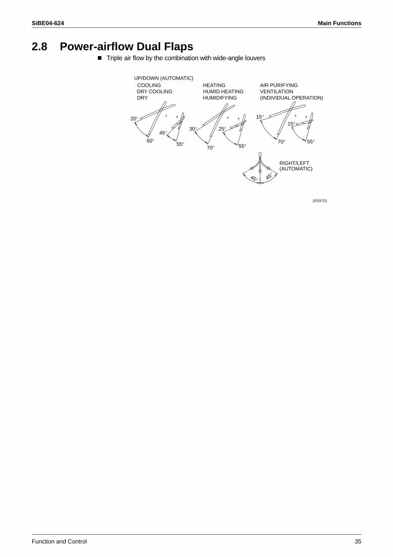
SiBE04-624 Main Functions
Function and Control 35
2.8 Power-airflow Dual FlapsTriple air flow by the combination with wide-angle louvers
(R5970)
45° 45°
15°
70° 55°
15°25°
55°70°
30°
60° 55°
20°
45°
RIGHT/LEFT(AUTOMATIC)
AIR PURIFYINGVENTILATION(INDIVIDUAL OPERATION)
UP/DOWN (AUTOMATIC)COOLINGDRY COOLINGDRY
HEATINGHUMID HEATINGHUMIDIFYING
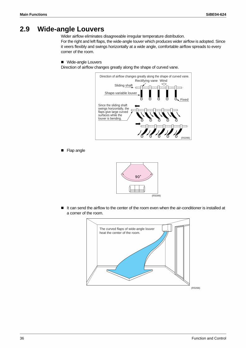
Main Functions SiBE04-624
36 Function and Control
2.9 Wide-angle LouversWider airflow eliminates disagreeable irregular temperature distribution.For the right and left flaps, the wide-angle louver which produces wider airflow is adopted. Since it veers flexibly and swings horizontally at a wide angle, comfortable airflow spreads to every corner of the room.
Wide-angle LouversDirection of airflow changes greatly along the shape of curved vane.
Flap angle
It can send the airflow to the center of the room even when the air-conditioner is installed at a corner of the room.
Direction of airflow changes greatly along the shape of curved vane.Rectifying vane Wind
Sliding shaft
Shape-variable louver
Fixed
Since the sliding shaftswings horizontally, theflaps give large curvedsurfaces while thelouver is bending.
(R5096)
(R5099)
The curved flaps of wide-angle louverheat the center of the room.
(R5098)
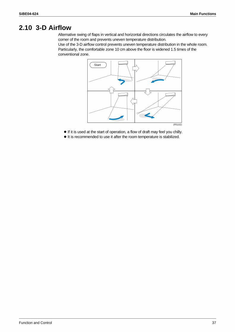
SiBE04-624 Main Functions
Function and Control 37
2.10 3-D AirflowAlternative swing of flaps in vertical and horizontal directions circulates the airflow to every corner of the room and prevents uneven temperature distribution.Use of the 3-D airflow control prevents uneven temperature distribution in the whole room. Particularly, the comfortable zone 10 cm above the floor is widened 1.5 times of the conventional zone.
If it is used at the start of operation, a flow of draft may feel you chilly. It is recommended to use it after the room temperature is stabilized.
Start
(R5102)
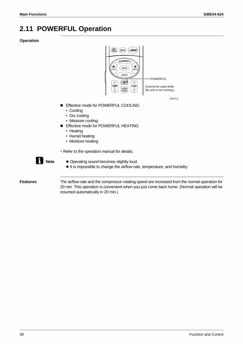
Main Functions SiBE04-624
38 Function and Control
2.11 POWERFUL Operation
Operation
Effective mode for POWERFUL COOLING• Cooling• Dry cooling• Moisture coolingEffective mode for POWERFUL HEATING• Heating• Humid heating• Moisture heating
∗ Refer to the operation manual for details.
Note Operating sound becomes slightly loud. It is impossible to change the airflow rate, temperature, and humidity.
Features The airflow rate and the compressor rotating speed are increased from the normal operation for 20 min. This operation is convenient when you just come back home. (Normal operation will be resumed automatically in 20 min.)
POWERFUL
(Cannot be used while the unit is not running.)
(R5971)
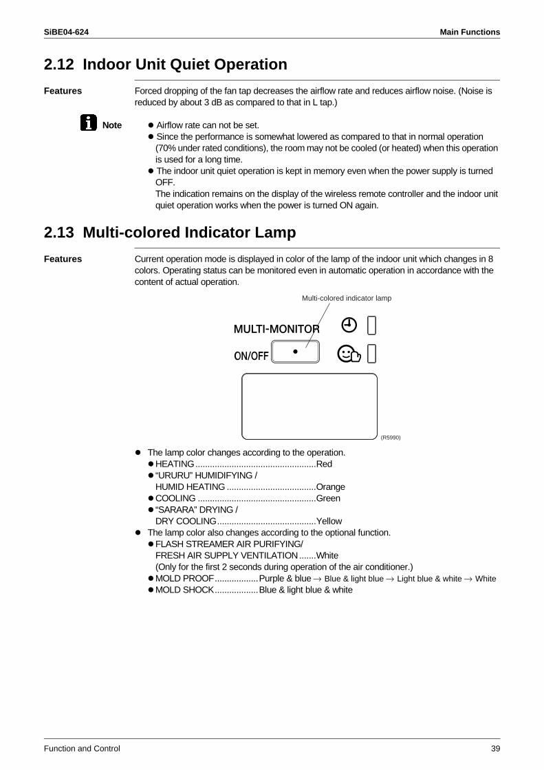
SiBE04-624 Main Functions
Function and Control 39
2.12 Indoor Unit Quiet Operation
Features Forced dropping of the fan tap decreases the airflow rate and reduces airflow noise. (Noise is reduced by about 3 dB as compared to that in L tap.)
Note Airflow rate can not be set. Since the performance is somewhat lowered as compared to that in normal operation (70% under rated conditions), the room may not be cooled (or heated) when this operation is used for a long time. The indoor unit quiet operation is kept in memory even when the power supply is turned OFF.The indication remains on the display of the wireless remote controller and the indoor unit quiet operation works when the power is turned ON again.
2.13 Multi-colored Indicator Lamp
Features Current operation mode is displayed in color of the lamp of the indoor unit which changes in 8 colors. Operating status can be monitored even in automatic operation in accordance with the content of actual operation.
The lamp color changes according to the operation.HEATING..................................................Red“URURU” HUMIDIFYING /HUMID HEATING .....................................OrangeCOOLING .................................................Green“SARARA” DRYING / DRY COOLING.........................................Yellow
The lamp color also changes according to the optional function.FLASH STREAMER AIR PURIFYING/FRESH AIR SUPPLY VENTILATION.......White(Only for the first 2 seconds during operation of the air conditioner.)MOLD PROOF..................Purple & blue Blue & light blue Light blue & white WhiteMOLD SHOCK..................Blue & light blue & white
(R5990)
Multi-colored indicator lamp
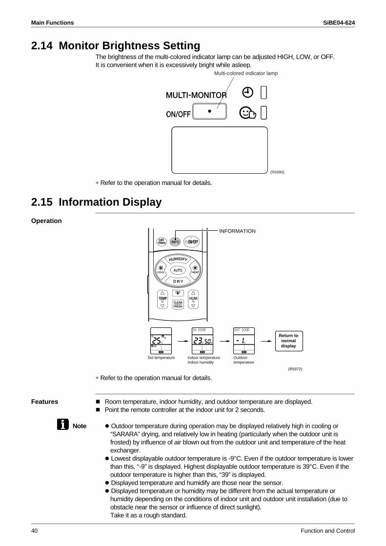
Main Functions SiBE04-624
40 Function and Control
2.14 Monitor Brightness SettingThe brightness of the multi-colored indicator lamp can be adjusted HIGH, LOW, or OFF.It is convenient when it is excessively bright while asleep.
∗ Refer to the operation manual for details.
2.15 Information Display
Operation
∗ Refer to the operation manual for details.
Features Room temperature, indoor humidity, and outdoor temperature are displayed.Point the remote controller at the indoor unit for 2 seconds.
Note Outdoor temperature during operation may be displayed relatively high in cooling or “SARARA” drying, and relatively low in heating (particularly when the outdoor unit is frosted) by influence of air blown out from the outdoor unit and temperature of the heat exchanger. Lowest displayable outdoor temperature is -9°C. Even if the outdoor temperature is lower than this, “-9” is displayed. Highest displayable outdoor temperature is 39°C. Even if the outdoor temperature is higher than this, “39” is displayed. Displayed temperature and humidify are those near the sensor. Displayed temperature or humidity may be different from the actual temperature or humidity depending on the conditions of indoor unit and outdoor unit installation (due to obstacle near the sensor or influence of direct sunlight).Take it as a rough standard.
(R5990)
Multi-colored indicator lamp
INFORMATION
(R5972)
Return tonormaldisplay
Set temperature Indoor temperatureIndoor humidity
Outdoortemperature
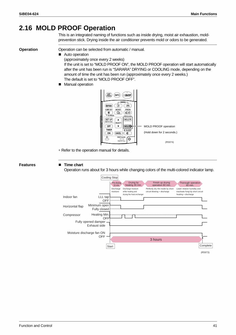
SiBE04-624 Main Functions
Function and Control 41
2.16 MOLD PROOF OperationThis is an integrated naming of functions such as inside drying, moist air exhaustion, mold-prevention stick. Drying inside the air conditioner prevents mold or odors to be generated.
Operation Operation can be selected from automatic / manual.Auto operation(approximately once every 2 weeks)If the unit is set to “MOLD PROOF ON”, the MOLD PROOF operation will start automatically after the unit has been run is “SARARA” DRYING or COOLING mode, depending on the amount of time the unit has been run (approximately once every 2 weeks.)The default is set to “MOLD PROOF OFF”.Manual operation
∗ Refer to the operation manual for details.
Features Time chartOperation runs about for 3 hours while changing colors of the multi-colored indicator lamp.
MOLD PROOF operation
(Hold down for 2 seconds.)
(R5974)
Indoor fan
Dischargemoisture
Horizontal flap
Pre-drying10 min.
Drying byheating 30 min.
Finish up dryingoperation 80 min.
Thorough operation60 min.
Discharge moisturewhile heating anddrying the heat exchanger
Perfectly dry the inside by shortcircuit blowing + discharge
Lower relative humidity and inactivate fungi by short circuit heating + discharge
Compressor
Fully opened damperExhaust side
Moisture discharge fan ONOFF
Start Complete
Cooling Stop
LLL tapOFF
Minimum openFully closed
Heating Min.OFF
3 hours
(R5973)
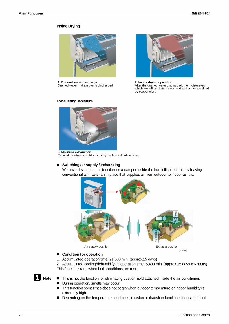
Main Functions SiBE04-624
42 Function and Control
Inside Drying
Exhausting Moisture
Switching air supply / exhaustingWe have developed this function on a damper inside the humidification unit, by leaving conventional air intake fan in place that supplies air from outdoor to indoor as it is.
Condition for operation1. Accumulated operation time: 21,600 min. (approx.15 days)2. Accumulated cooling/dehumidifying operation time: 5,400 min. (approx.15 days x 6 hours)This function starts when both conditions are met.
Note This is not the function for eliminating dust or mold attached inside the air conditioner.During operation, smells may occur.This function sometimes does not begin when outdoor temperature or indoor humidity is extremely high.Depending on the temperature conditions, moisture exhaustion function is not carried out.
1. Drained water dischargeDrained water in drain pan is discharged.
2. Inside drying operationAfter the drained water discharged, the moisture etc. which are left on drain pan or heat exchanger are dried by evaporation.
3. Moisture exhaustionExhaust moisture to outdoors using the humidification hose.
Air supply position Exhaust position
To O
utdo
or
To In
door
From
Indo
or
From
Out
door
(R3374)
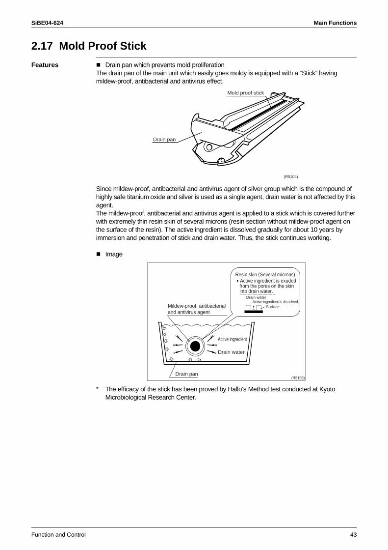
SiBE04-624 Main Functions
Function and Control 43
2.17 Mold Proof Stick
Features Drain pan which prevents mold proliferationThe drain pan of the main unit which easily goes moldy is equipped with a “Stick” having mildew-proof, antibacterial and antivirus effect.
Since mildew-proof, antibacterial and antivirus agent of silver group which is the compound of highly safe titanium oxide and silver is used as a single agent, drain water is not affected by this agent.The mildew-proof, antibacterial and antivirus agent is applied to a stick which is covered further with extremely thin resin skin of several microns (resin section without mildew-proof agent on the surface of the resin). The active ingredient is dissolved gradually for about 10 years by immersion and penetration of stick and drain water. Thus, the stick continues working.
Image
* The efficacy of the stick has been proved by Hallo’s Method test conducted at Kyoto Microbiological Research Center.
Mold proof stick
Drain pan
(R5104)
Mildew-proof, antibacterial and antivirus agent
Active ingredient
Drain water
Drain pan
Drain waterActive ingredient is dissolved.
Surface
Resin skin (Several microns) Active ingredient is exuded from the pores on the skininto drain water.
(R5105)
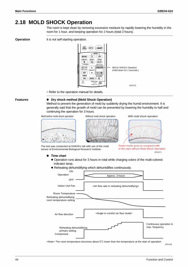
Main Functions SiBE04-624
44 Function and Control
2.18 MOLD SHOCK OperationThe room is kept clean by removing excessive moisture by rapidly lowering the humidity in the room for 1 hour, and keeping operation for 2 hours (total 3 hours).
Operation It is not self-starting operation.
∗ Refer to the operation manual for details.
Features Dry shock method (Mold Shock Operation)Method to prevent the generation of mold by suddenly drying the humid environment. It is generally said that the growth of mold can be prevented by lowering the humidity to half and continuing the operation for 3 hours.
Time chart Operation runs about for 3 hours in rotal while charging colors of the multi-colored indicator lamp. Reheating dehumidifying which dehumidifies continuously.
MOLD SHOCK Opeation(Hold down for 2 seconds.)
(R5975)
Mold before mold shock operation
Fewer molds grow as compared within the case without Mold Shock Operation.
Without mold shock operation With mold shock operation
(R5107)
The test was conducted at DAIKIN’s lab with use of the mold sensor of Environmental Biological Research Institute.
OperationON
<Air flow rate in reheating dehumidifying>Indoor Unit Fan
Reheating dehumidifyingroom temperature setting
Room Temperature
Air flow direction <Angle in comfort air flow mode>
Compressor
Continuous operation inmax. frequencyReheating dehumidifying
primary setting.
OFF
Approx. 3 hours
(R5108)<Note> The room temperature becomes about 5˚C lower than the temperature at the start of operation.
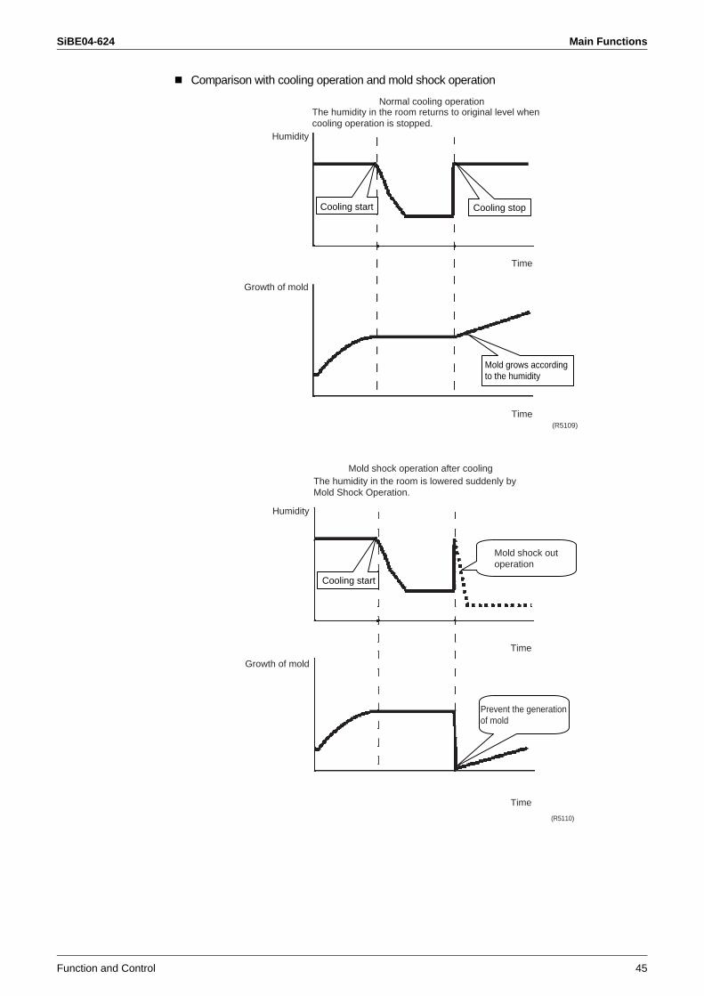
SiBE04-624 Main Functions
Function and Control 45
Comparison with cooling operation and mold shock operation
The humidity in the room returns to original level whencooling operation is stopped.
Cooling start
Humidity
Normal cooling operation
Growth of mold
Cooling stop
Mold grows according to the humidity
Time
Time(R5109)
The humidity in the room is lowered suddenly byMold Shock Operation.
Humidity
Mold shock operation after cooling
Growth of mold
Mold shock out operation
Prevent the generation of mold
Cooling start
Time
Time
(R5110)
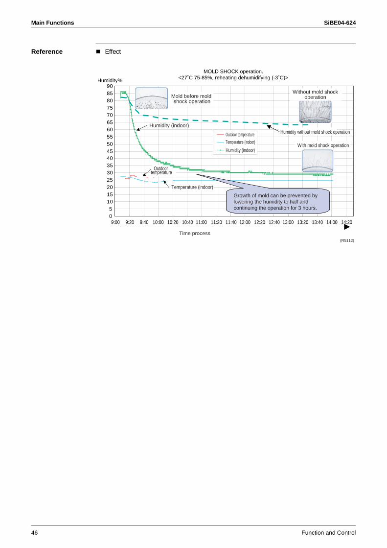
Main Functions SiBE04-624
46 Function and Control
Reference Effect
05
1015202530354045505560657075808590
9:00 9:20 9:40 10:00 10:20 10:40 11:00 11:20 11:40 12:00 12:20 12:40 13:00 13:20 13:40 14:00 14:20
Humidity%
Temperature (indoor)
Outdoor temperature
MOLD SHOCK operation.<27˚C 75-85%, reheating dehumidifying (-3˚C)>
Mold before mold shock operation
Without mold shockoperation
Humidity (indoor)Humidity without mold shock operationOutdoor temperature
Temperature (indoor)
Humidity (indoor)With mold shock operation
(R5112)
Growth of mold can be prevented by lowering the humidity to half and continuing the operation for 3 hours.
Time process
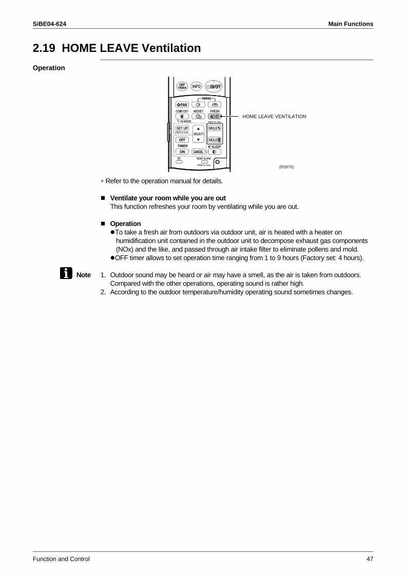
SiBE04-624 Main Functions
Function and Control 47
2.19 HOME LEAVE Ventilation
Operation
∗ Refer to the operation manual for details.
Ventilate your room while you are outThis function refreshes your room by ventilating while you are out.
OperationTo take a fresh air from outdoors via outdoor unit, air is heated with a heater on humidification unit contained in the outdoor unit to decompose exhaust gas components (NOx) and the like, and passed through air intake filter to eliminate pollens and mold.OFF timer allows to set operation time ranging from 1 to 9 hours (Factory set: 4 hours).
Note 1. Outdoor sound may be heard or air may have a smell, as the air is taken from outdoors. Compared with the other operations, operating sound is rather high.
2. According to the outdoor temperature/humidity operating sound sometimes changes.
HOME LEAVE VENTILATION
(R5976)
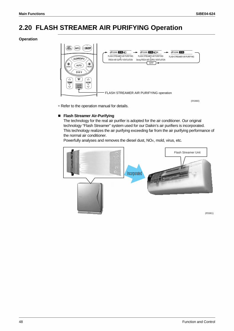
Main Functions SiBE04-624
48 Function and Control
2.20 FLASH STREAMER AIR PURIFYING Operation
Operation
∗ Refer to the operation manual for details.
Flash Streamer Air-PurifyingThe technology for the real air purifier is adopted for the air conditioner. Our original technology “Flash Streamer” system used for our Daikin’s air purifiers is incorporated.This technology realizes the air purifying exceeding far from the air purifying performance of the normal air conditioner.Powerfully analyses and removes the diesel dust, NOX, mold, virus, etc.
FLASH STREAMER AIR PURIFYING operation
FLASH STREAMER AIR PURIFYING+
FRESH AIR SUPPLY VENTILATION
FLASH STREAMER AIR PURIFYING+
Strong FRESH AIR SUPPLY VENTILATIONFLASH STREAMER AIR PURIFYING
OFF
(R5980)
Flash Streamer Unit
Incorporated
(R5981)
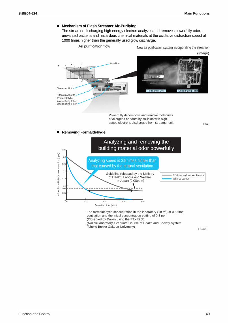
SiBE04-624 Main Functions
Function and Control 49
Mechanism of Flash Streamer Air-PurifyingThe streamer discharging high energy electron analyzes and removes powerfully odor, unwanted bacteria and hazardous chemical materials at the oxidative distraction speed of 1000 times higher than the generally used glow discharge.
Removing Formaldehyde
Powerfully decompose and remove molecules of allergens or odors by collision with high-speed electrons discharged from streamer unit.
Air purification flow New air purification system incorporating the streamer
Pre-filter
Streamer Unit Deodorizing FilterStreamer Unit
Titanium Apatite Photocatalytic Air-purifying FilterDeodorizing Filter
(Image)
(R5982)
0.35
0.3
0.25
0.2
0.15
0.10.08
0.05
01000 200 300 400
Analyzing and removing the building material odor powerfully
The formaldehyde concentration in the laboratory (10 m2) at 0.5-time ventilation and the initial concentration setting of 0.3 ppm (Observed by Daikin using the FTXR28E)(Nozaki laboratory, Graduate Course of Health and Society System, Tohoku Bunka Gakuen University)
0.5-time natural ventilationWith streamer
Analyzing speed is 3.5 times higher than that caused by the natural ventilation.
Guideline released by the Ministry of Health, Labour and Welfare
in Japan (0.08ppm)
Indo
or fo
rmal
dehy
de c
once
ntra
tion
(ppm
)
Operation time (min.)
(R5983)
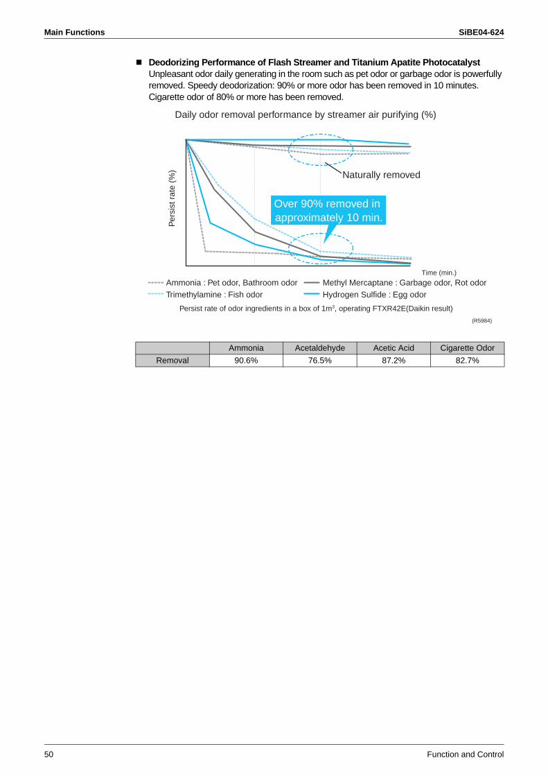
Main Functions SiBE04-624
50 Function and Control
Deodorizing Performance of Flash Streamer and Titanium Apatite PhotocatalystUnpleasant odor daily generating in the room such as pet odor or garbage odor is powerfully removed. Speedy deodorization: 90% or more odor has been removed in 10 minutes.Cigarette odor of 80% or more has been removed.
Ammonia Acetaldehyde Acetic Acid Cigarette Odor
Removal 90.6% 76.5% 87.2% 82.7%
Daily odor removal performance by streamer air purifying (%)
Persist rate of odor ingredients in a box of 1m3, operating FTXR42E(Daikin result)
Per
sist
rat
e (%
)
Ammonia : Pet odor, Bathroom odorTrimethylamine : Fish odor
Methyl Mercaptane : Garbage odor, Rot odorHydrogen Sulfide : Egg odor
Time (min.)
Over 90% removed in approximately 10 min.
Naturally removed
(R5984)
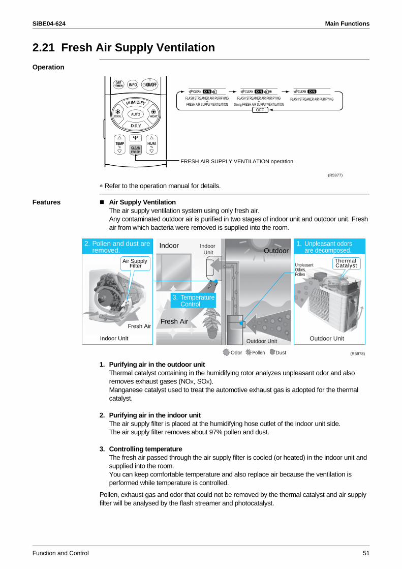
SiBE04-624 Main Functions
Function and Control 51
2.21 Fresh Air Supply Ventilation
Operation
∗ Refer to the operation manual for details.
Features Air Supply VentilationThe air supply ventilation system using only fresh air.Any contaminated outdoor air is purified in two stages of indoor unit and outdoor unit. Fresh air from which bacteria were removed is supplied into the room.
1. Purifying air in the outdoor unitThermal catalyst containing in the humidifying rotor analyzes unpleasant odor and also removes exhaust gases (NOX, SOX).Manganese catalyst used to treat the automotive exhaust gas is adopted for the thermal catalyst.
2. Purifying air in the indoor unitThe air supply filter is placed at the humidifying hose outlet of the indoor unit side.The air supply filter removes about 97% pollen and dust.
3. Controlling temperatureThe fresh air passed through the air supply filter is cooled (or heated) in the indoor unit and supplied into the room.You can keep comfortable temperature and also replace air because the ventilation is performed while temperature is controlled.
Pollen, exhaust gas and odor that could not be removed by the thermal catalyst and air supply filter will be analysed by the flash streamer and photocatalyst.
FRESH AIR SUPPLY VENTILATION operation
FLASH STREAMER AIR PURIFYING+
FRESH AIR SUPPLY VENTILATION
FLASH STREAMER AIR PURIFYING+
Strong FRESH AIR SUPPLY VENTILATIONFLASH STREAMER AIR PURIFYING
OFF
(R5977)
OutdoorIndoor
Odor Pollen Dust
Indoor Unit
Fresh AirFresh Air
Air Supply Filter
Thermal Catalyst
Outdoor UnitOutdoor Unit
Indoor Unit
Unpleasant Odors, Pollen
2. Pollen and dust are removed.
3. Temperature Control
1. Unpleasant odors are decomposed.
(R5978)
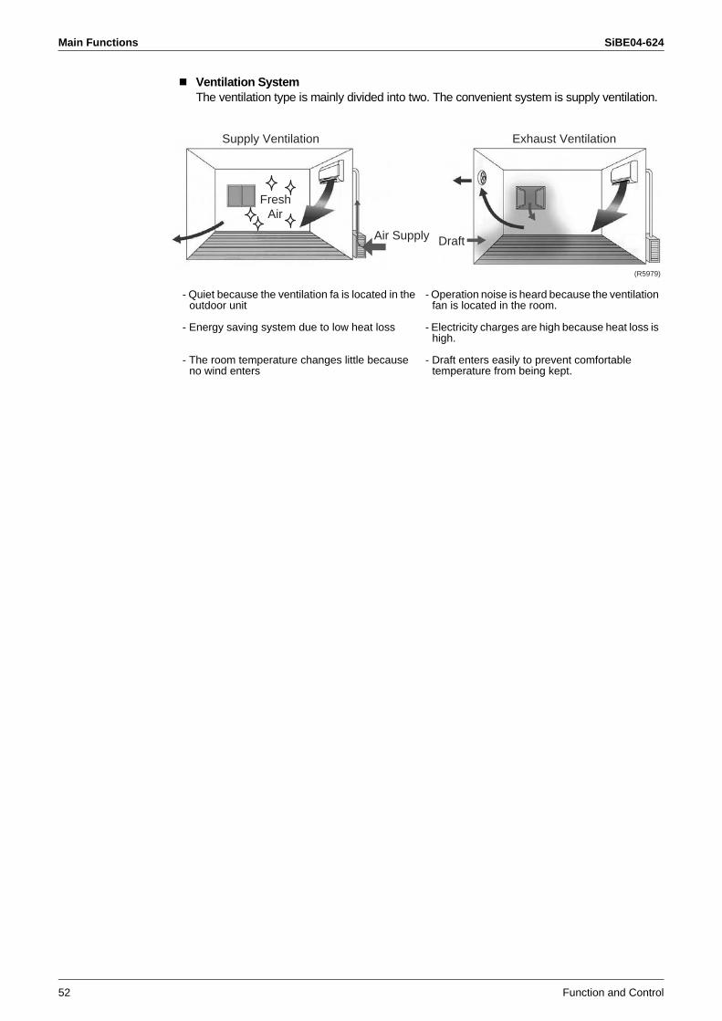
Main Functions SiBE04-624
52 Function and Control
Ventilation SystemThe ventilation type is mainly divided into two. The convenient system is supply ventilation.
- Quiet because the ventilation fa is located in the outdoor unit
- Energy saving system due to low heat loss
- The room temperature changes little because no wind enters
- Operation noise is heard because the ventilation fan is located in the room.
- Electricity charges are high because heat loss is high.
- Draft enters easily to prevent comfortable temperature from being kept.
Exhaust Ventilation
Air Supply Draft
Air
Supply Ventilation
Fresh
(R5979)
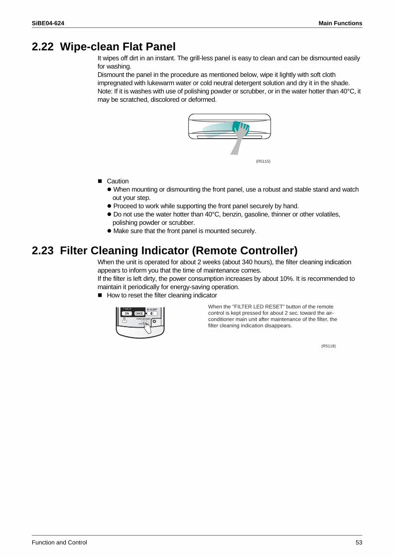
SiBE04-624 Main Functions
Function and Control 53
2.22 Wipe-clean Flat PanelIt wipes off dirt in an instant. The grill-less panel is easy to clean and can be dismounted easily for washing.Dismount the panel in the procedure as mentioned below, wipe it lightly with soft cloth impregnated with lukewarm water or cold neutral detergent solution and dry it in the shade.Note: If it is washes with use of polishing powder or scrubber, or in the water hotter than 40°C, it may be scratched, discolored or deformed.
Caution When mounting or dismounting the front panel, use a robust and stable stand and watch out your step. Proceed to work while supporting the front panel securely by hand. Do not use the water hotter than 40°C, benzin, gasoline, thinner or other volatiles, polishing powder or scrubber. Make sure that the front panel is mounted securely.
2.23 Filter Cleaning Indicator (Remote Controller)When the unit is operated for about 2 weeks (about 340 hours), the filter cleaning indication appears to inform you that the time of maintenance comes.If the filter is left dirty, the power consumption increases by about 10%. It is recommended to maintain it periodically for energy-saving operation.
How to reset the filter cleaning indicator
(R5115)
(R5118)
When the "FILTER LED RESET" button of the remote control is kept pressed for about 2 sec. toward the air-conditioner main unit after maintenance of the filter, the filter cleaning indication disappears.
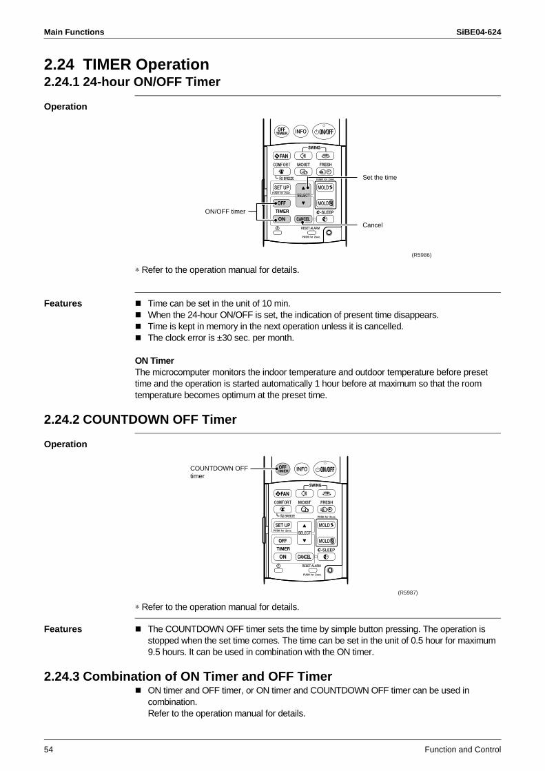
Main Functions SiBE04-624
54 Function and Control
2.24 TIMER Operation2.24.1 24-hour ON/OFF Timer
Operation
∗ Refer to the operation manual for details.
Features Time can be set in the unit of 10 min.When the 24-hour ON/OFF is set, the indication of present time disappears.Time is kept in memory in the next operation unless it is cancelled.The clock error is ±30 sec. per month.
ON TimerThe microcomputer monitors the indoor temperature and outdoor temperature before preset time and the operation is started automatically 1 hour before at maximum so that the room temperature becomes optimum at the preset time.
2.24.2 COUNTDOWN OFF Timer
Operation
∗ Refer to the operation manual for details.
Features The COUNTDOWN OFF timer sets the time by simple button pressing. The operation is stopped when the set time comes. The time can be set in the unit of 0.5 hour for maximum 9.5 hours. It can be used in combination with the ON timer.
2.24.3 Combination of ON Timer and OFF TimerON timer and OFF timer, or ON timer and COUNTDOWN OFF timer can be used in combination.Refer to the operation manual for details.
Set the time
Cancel
ON/OFF timer
(R5986)
COUNTDOWN OFFtimer
(R5987)
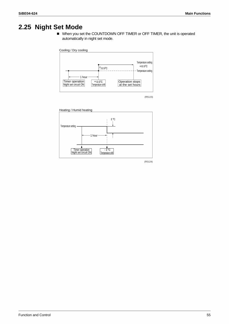
SiBE04-624 Main Functions
Function and Control 55
2.25 Night Set ModeWhen you set the COUNTDOWN OFF TIMER or OFF TIMER, the unit is operated automatically in night set mode.
Cooling / Dry cooling
Temperature setting
Temperature setting
1 hourTimer operationNight set circuit ON
+ Temperature shift
Operation stops at the set hours
(R5123)
Heating / Humid heating
Temperature setting
1 hour
Timer operationNight set circuit ON
- Temperature shift
(R5124)
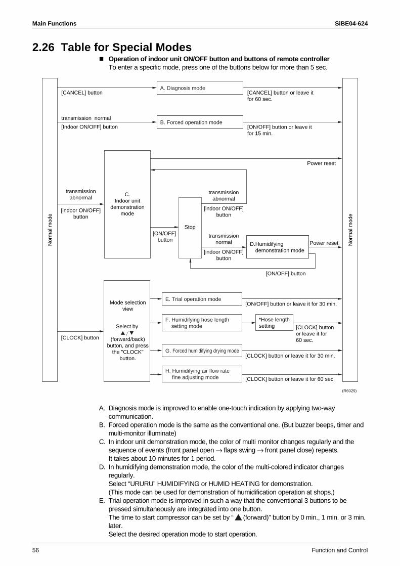
Main Functions SiBE04-624
56 Function and Control
2.26 Table for Special ModesOperation of indoor unit ON/OFF button and buttons of remote controller To enter a specific mode, press one of the buttons below for more than 5 sec.
A. Diagnosis mode is improved to enable one-touch indication by applying two-way communication.
B. Forced operation mode is the same as the conventional one. (But buzzer beeps, timer and multi-monitor illuminate)
C. In indoor unit demonstration mode, the color of multi monitor changes regularly and the sequence of events (front panel open → flaps swing → front panel close) repeats.It takes about 10 minutes for 1 period.
D. In humidifying demonstration mode, the color of the multi-colored indicator changes regularly.Select “URURU” HUMIDIFYING or HUMID HEATING for demonstration.(This mode can be used for demonstration of humidification operation at shops.)
E. Trial operation mode is improved in such a way that the conventional 3 buttons to be pressed simultaneously are integrated into one button.The time to start compressor can be set by “ (forward)” button by 0 min., 1 min. or 3 min. later.Select the desired operation mode to start operation.
Nor
mal
mod
e
Nor
mal
mod
e
A. Diagnosis mode
B. Forced operation mode
E. Trial operation mode
*Hose length setting
D.Humidifying demonstration mode
F. Humidifying hose length setting mode
G. Forced humidifying drying mode
H. Humidifying air flow rate fine adjusting mode
Stop
[CANCEL] button or leave it for 60 sec.
[ON/OFF] button or leave it for 15 min.
[ON/OFF] button or leave it for 30 min.
[CLOCK] button or leave it for 30 min.
[CLOCK] button or leave it for 60 sec.
transmissionabnormal
[indoor ON/OFF]button
transmissionabnormal
[indoor ON/OFF]button
transmissionnormal
[indoor ON/OFF]button
[CLOCK] button or leave it for 60 sec.
transmission normal
[Indoor ON/OFF] button
[CANCEL] button
[ON/OFF] button
[ON/OFF] button
Power reset
Power reset
C.Indoor unit
demonstrationmode
(R6029)
[CLOCK] button
Mode selection view
Select by
(forward/back) button, and press
the "CLOCK" button.
SiBE04-624 Main Functions
Function and Control 57
F. For humidifying hose length setting(*), refer to page 93.G. In forced humidifying drying mode, drying operation continues for approx. 30 min. for
service.Start this operation after removing all moisture inside the hose.During forced drying operation, cooling, heating or dehumidifying operation is unavailable.
H. Humidifying air flow rate fine adjusting mode allows to fine-tune the speed of the humidification fan around ±10 % relative to AUTO. If you want to increase the air flow rate, set to [H], and to decrease the air flow rate, set to [L].
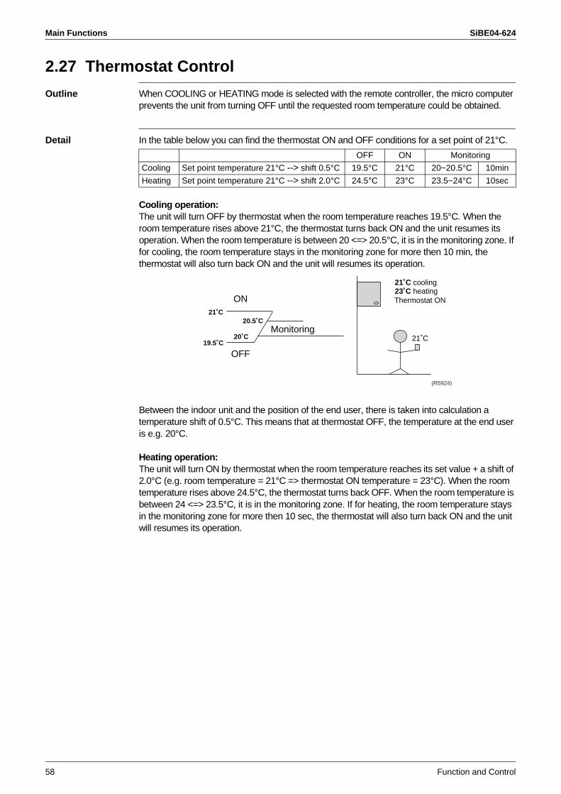
Main Functions SiBE04-624
58 Function and Control
2.27 Thermostat Control
Outline When COOLING or HEATING mode is selected with the remote controller, the micro computer prevents the unit from turning OFF until the requested room temperature could be obtained.
Detail In the table below you can find the thermostat ON and OFF conditions for a set point of 21°C.
Cooling operation:The unit will turn OFF by thermostat when the room temperature reaches 19.5°C. When the room temperature rises above 21°C, the thermostat turns back ON and the unit resumes its operation. When the room temperature is between 20 <=> 20.5°C, it is in the monitoring zone. If for cooling, the room temperature stays in the monitoring zone for more then 10 min, the thermostat will also turn back ON and the unit will resumes its operation.
Between the indoor unit and the position of the end user, there is taken into calculation a temperature shift of 0.5°C. This means that at thermostat OFF, the temperature at the end user is e.g. 20°C.
Heating operation:The unit will turn ON by thermostat when the room temperature reaches its set value + a shift of 2.0°C (e.g. room temperature = 21°C => thermostat ON temperature = 23°C). When the room temperature rises above 24.5°C, the thermostat turns back OFF. When the room temperature is between 24 <=> 23.5°C, it is in the monitoring zone. If for heating, the room temperature stays in the monitoring zone for more then 10 sec, the thermostat will also turn back ON and the unit will resumes its operation.
OFF ON Monitoring
Cooling Set point temperature 21°C --> shift 0.5°C 19.5°C 21°C 20~20.5°C 10min
Heating Set point temperature 21°C --> shift 2.0°C 24.5°C 23°C 23.5~24°C 10sec
21˚C cooling 23˚C heatingThermostat ON
21˚C
21˚C20.5˚C
20˚C19.5˚C
ON
OFF
Monitoring
(R5924)
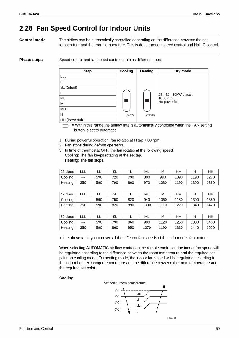
SiBE04-624 Main Functions
Function and Control 59
2.28 Fan Speed Control for Indoor Units
Control mode The airflow can be automatically controlled depending on the difference between the set temperature and the room temperature. This is done through speed control and Hall IC control.
Phase steps Speed control and fan speed control contains different steps:.
= Within this range the airflow rate is automatically controlled when the FAN setting button is set to automatic.
1. During powerful operation, fan rotates at H tap + 80 rpm.2. Fan stops during defrost operation.3. In time of thermostat OFF, the fan rotates at the following speed.
Cooling: The fan keeps rotating at the set tap.Heating: The fan stops.
In the above table you can see all the different fan speeds of the indoor units fan motor.
When selecting AUTOMATIC air flow control on the remote controller, the indoor fan speed will be regulated according to the difference between the room temperature and the required set point on cooling mode. On heating mode, the indoor fan speed will be regulated according to the indoor heat exchanger temperature and the difference between the room temperature and the required set point.
Cooling
Step Cooling Heating Dry mode
LLL
28 · 42 · 50kW class : 1000 rpmNo powerful
LL
SL (Silent)
L
ML
M
MH
H
HH (Powerful)(R4085) (R4085)
28 class LLL LL SL L ML M HM H HH
Cooling --- 590 720 790 890 990 1090 1190 1270
Heating 350 590 790 860 970 1080 1190 1300 1380
42 class LLL LL SL L ML M HM H HH
Cooling --- 590 750 820 940 1060 1180 1300 1380
Heating 350 590 820 890 1000 1110 1220 1340 1420
50 class LLL LL SL L ML M HM H HH
Cooling --- 590 790 860 990 1120 1250 1380 1460
Heating 350 590 860 950 1070 1190 1310 1440 1520
L
LM
M
MH3˚C
2˚C
1˚C
0˚C
Set point - room temperature
(R5925)
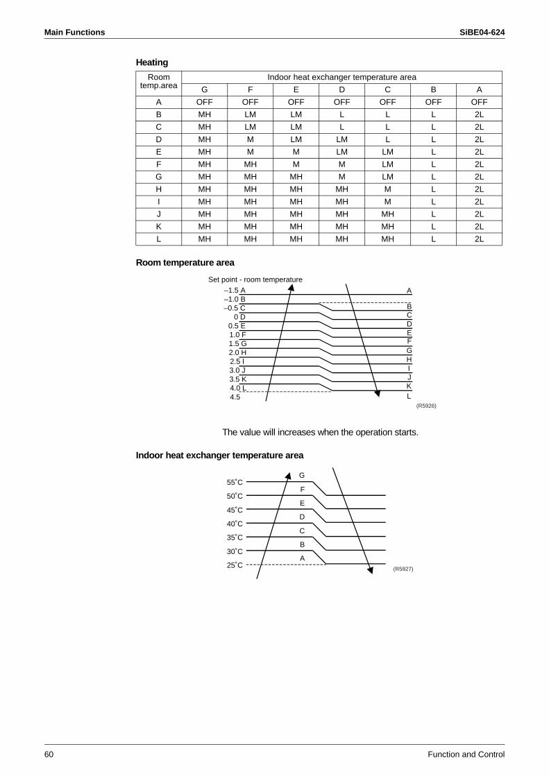
Main Functions SiBE04-624
60 Function and Control
Heating
Room temperature area
The value will increases when the operation starts.
Indoor heat exchanger temperature area
Roomtemp.area
Indoor heat exchanger temperature area
G F E D C B A
A OFF OFF OFF OFF OFF OFF OFF
B MH LM LM L L L 2L
C MH LM LM L L L 2L
D MH M LM LM L L 2L
E MH M M LM LM L 2L
F MH MH M M LM L 2L
G MH MH MH M LM L 2L
H MH MH MH MH M L 2L
I MH MH MH MH M L 2L
J MH MH MH MH MH L 2L
K MH MH MH MH MH L 2L
L MH MH MH MH MH L 2L
C
E
G
IJ
A
K
B
D
F
H
L
–1.0 B
0 D
1.0 F
2.0 H
3.0 J
4.0 L
–1.5 A
–0.5 C
0.5 E
1.5 G
2.5 I
3.5 K
4.5
Set point - room temperature
(R5926)
55˚C
50˚C
45˚C
40˚C
35˚C
30˚C
25˚C
G
F
E
D
C
B
A(R5927)
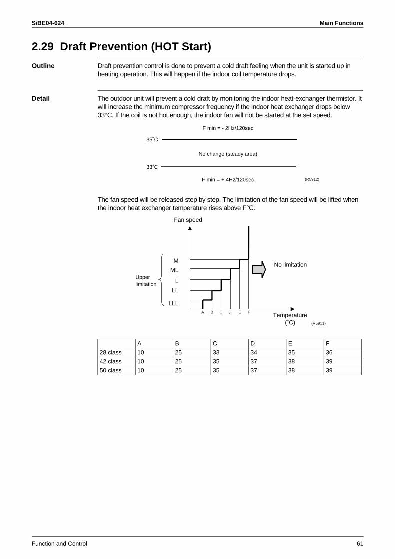
SiBE04-624 Main Functions
Function and Control 61
2.29 Draft Prevention (HOT Start)
Outline Draft prevention control is done to prevent a cold draft feeling when the unit is started up in heating operation. This will happen if the indoor coil temperature drops.
Detail The outdoor unit will prevent a cold draft by monitoring the indoor heat-exchanger thermistor. It will increase the minimum compressor frequency if the indoor heat exchanger drops below 33°C. If the coil is not hot enough, the indoor fan will not be started at the set speed.
The fan speed will be released step by step. The limitation of the fan speed will be lifted when the indoor heat exchanger temperature rises above F°C.
A B C D E F
28 class 10 25 33 34 35 36
42 class 10 25 35 37 38 39
50 class 10 25 35 37 38 39
No change (steady area)
35˚C
33˚C
F min = + 4Hz/120sec
F min = - 2Hz/120sec
(R5912)
LLL
LL
L
ML
M
A B C D E F
No limitation
Fan speed
Temperature(˚C)
Upperlimitation
(R5911)
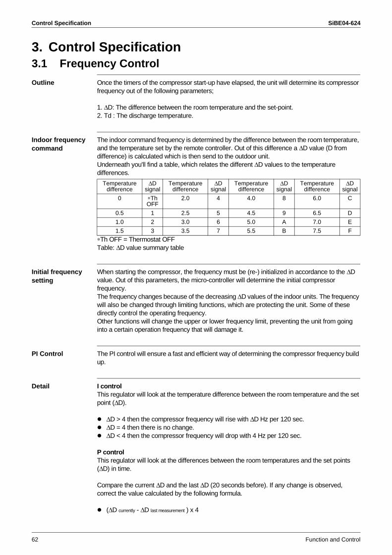
Control Specification SiBE04-624
62 Function and Control
3. Control Specification3.1 Frequency Control
Outline Once the timers of the compressor start-up have elapsed, the unit will determine its compressor frequency out of the following parameters;
1. ∆D: The difference between the room temperature and the set-point.2. Td : The discharge temperature.
Indoor frequency command
The indoor command frequency is determined by the difference between the room temperature, and the temperature set by the remote controller. Out of this difference a ∆D value (D from difference) is calculated which is then send to the outdoor unit. Underneath you'll find a table, which relates the different ∆D values to the temperature differences.
∗Th OFF = Thermostat OFFTable: ∆D value summary table
Initial frequency setting
When starting the compressor, the frequency must be (re-) initialized in accordance to the ∆D value. Out of this parameters, the micro-controller will determine the initial compressor frequency.The frequency changes because of the decreasing ∆D values of the indoor units. The frequency will also be changed through limiting functions, which are protecting the unit. Some of these directly control the operating frequency. Other functions will change the upper or lower frequency limit, preventing the unit from going into a certain operation frequency that will damage it.
PI Control The PI control will ensure a fast and efficient way of determining the compressor frequency build up.
Detail I controlThis regulator will look at the temperature difference between the room temperature and the set point (∆D).
∆D > 4 then the compressor frequency will rise with ∆D Hz per 120 sec.∆D = 4 then there is no change.∆D < 4 then the compressor frequency will drop with 4 Hz per 120 sec.
P controlThis regulator will look at the differences between the room temperatures and the set points (∆D) in time.
Compare the current ∆D and the last ∆D (20 seconds before). If any change is observed, correct the value calculated by the following formula.
(∆D currently - ∆D last measurement ) x 4
Temperature difference
∆D signal
Temperature difference
∆D signal
Temperature difference
∆D signal
Temperature difference
∆D signal
0 ∗Th OFF
2.0 4 4.0 8 6.0 C
0.5 1 2.5 5 4.5 9 6.5 D
1.0 2 3.0 6 5.0 A 7.0 E
1.5 3 3.5 7 5.5 B 7.5 F
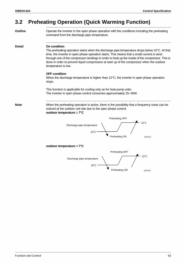
SiBE04-624 Control Specification
Function and Control 63
3.2 Preheating Operation (Quick Warming Function)
Outline Operate the inverter in the open phase operation with the conditions including the preheating command from the discharge pipe temperature.
Detail On conditionThe preheating operation starts when the discharge pipe temperature drops below 10°C. At that time, the inverter in open phase operation starts. This means that a small current is send through one of the compressor windings in order to heat up the inside of the compressor. This is done in order to prevent liquid compression at start up of the compressor when the outdoor temperature is low.
OFF conditionWhen the discharge temperature is higher than 12°C, the inverter in open phase operation stops.
This function is applicable for cooling only as for heat pump units.The inverter in open phase control consumes approximately 25~40W.
Note When the preheating operation is active, there is the possibility that a frequency noise can be noticed at the outdoor unit site due to the open phase control.outdoor temperature ≥ 7°C
outdoor temperature < 7°C
10˚C
Preheating ON
Preheating OFF
12˚CDischarge pipe temperature
(R5922)
20˚C
Preheating ON
Preheating OFF
22˚CDischarge pipe temperature
(R5923)
Control Specification SiBE04-624
64 Function and Control
3.3 Four-way Valve Operation
Outline Because the four-way valve only operates properly when there is an adequate pressure difference, the four-way valve compensation function has been implemented to insure this minimal pressure difference.
Detail The four-way valve compensation function insures a good four-way valve operation by demanding a certain minimal operation frequency for a certain time. By doing this, the unit is ensuring the switching of the four-way valve.When this function is enabled, the unit will not look at the other safeties (with the exception of input current control).
The four-way valve function compensation is engaged in four casesWhen starting the compressor for heating.When the operation mode is changed.When starting the compressor for defrosting.When starting the compressor after a power failure (auto-restart).
No power to the valve --> cooling.Power to the valve --> heating.
Frequency [Hz] Time [sec]
Cooling 52
60Heating
outdoor temperature < 16°C 52
outdoor temperature ≥ 16°C - 0.9 x outdoor temperature + 68
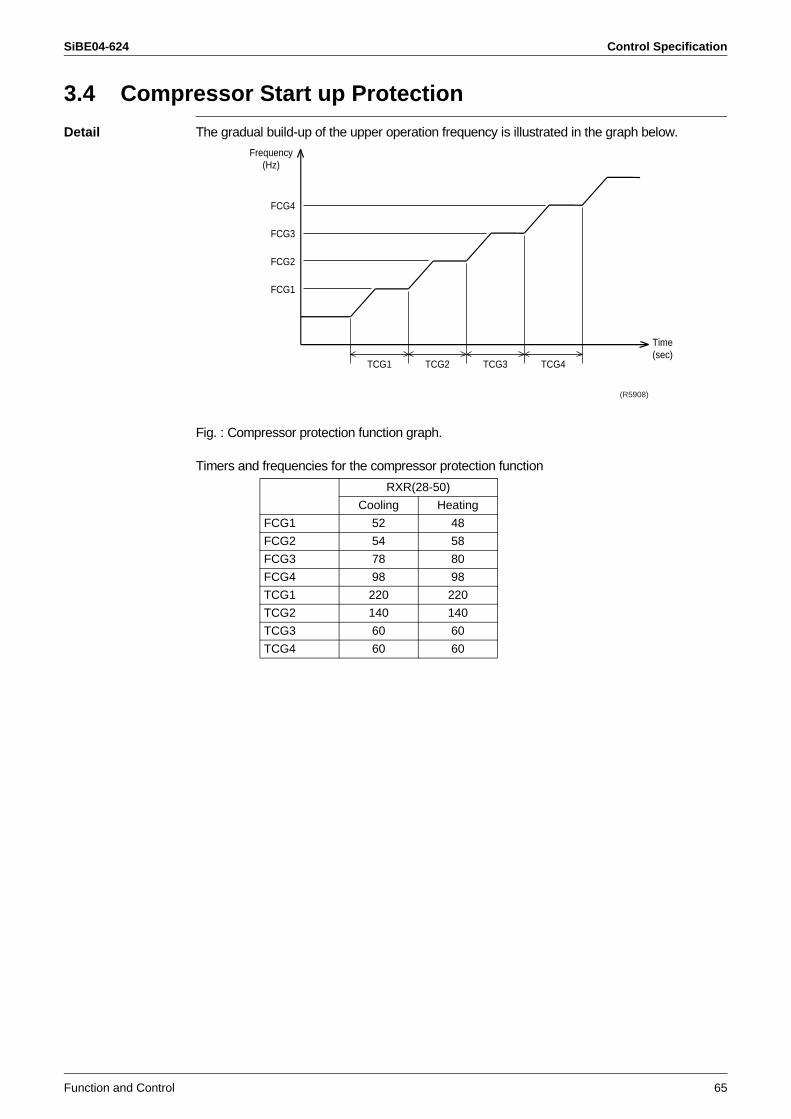
SiBE04-624 Control Specification
Function and Control 65
3.4 Compressor Start up Protection
Detail The gradual build-up of the upper operation frequency is illustrated in the graph below.
Fig. : Compressor protection function graph.
Timers and frequencies for the compressor protection function
RXR(28-50)
Cooling Heating
FCG1 52 48
FCG2 54 58
FCG3 78 80
FCG4 98 98
TCG1 220 220
TCG2 140 140
TCG3 60 60
TCG4 60 60
TCG1 TCG2 TCG3 TCG4
FCG4
Frequency(Hz)
FCG3
FCG2
FCG1
(R5908)
Time(sec)
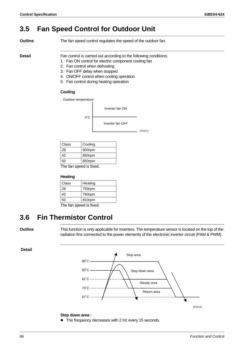
Control Specification SiBE04-624
66 Function and Control
3.5 Fan Speed Control for Outdoor Unit
Outline The fan speed control regulates the speed of the outdoor fan.
Detail Fan control is carried out according to the following conditions.1. Fan ON control for electric component cooling fan2. Fan control when defrosting3. Fan OFF delay when stopped 4. ON/OFF control when cooling operation5. Fan control during heating operation
Cooling
The fan speed is fixed.
Heating
The fan speed is fixed.
3.6 Fin Thermistor Control
Outline This function is only applicable for inverters. The temperature sensor is located on the top of the radiation fins connected to the power elements of the electronic inverter circuit (PAM & PWM).
Detail
Step down area : The frequency decreases with 2 Hz every 15 seconds.
Class Cooling
28 800rpm
42 850rpm
50 850rpm
Class Heating
28 750rpm
42 760rpm
50 810rpm
Inverter fan OFF
Inverter fan ON
Outdoor temperature
0˚C
(R5921)
Stop area
Steady area
Return area
Step down area
86˚C
83˚C
81˚C
73˚C
67˚C
(R5916)
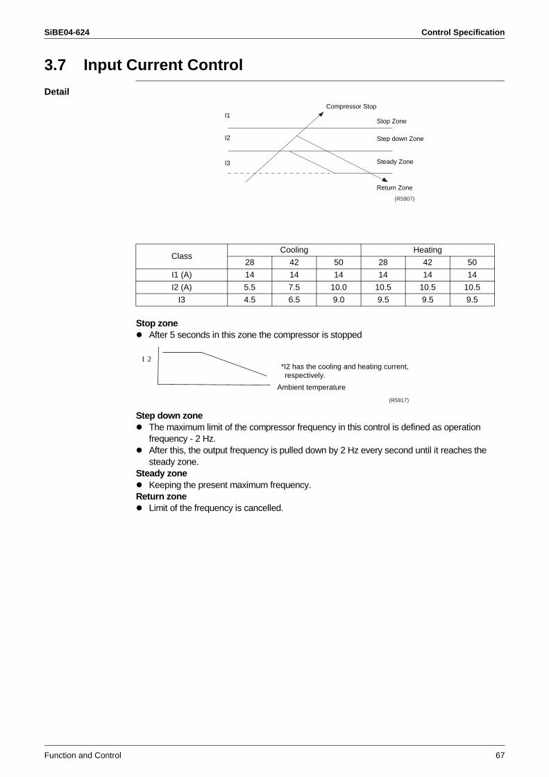
SiBE04-624 Control Specification
Function and Control 67
3.7 Input Current Control
Detail
Stop zoneAfter 5 seconds in this zone the compressor is stopped
Step down zoneThe maximum limit of the compressor frequency in this control is defined as operation frequency - 2 Hz.After this, the output frequency is pulled down by 2 Hz every second until it reaches the steady zone.
Steady zoneKeeping the present maximum frequency.
Return zoneLimit of the frequency is cancelled.
ClassCooling Heating
28 42 50 28 42 50
I1 (A) 14 14 14 14 14 14
I2 (A) 5.5 7.5 10.0 10.5 10.5 10.5
I3 4.5 6.5 9.0 9.5 9.5 9.5
Compressor Stop
Step down Zone
Stop Zone
Steady Zone
Return Zone
I1
I2
I3
(R5907)
Ambient temperature
I 2*I2 has the cooling and heating current, respectively.
(R5917)
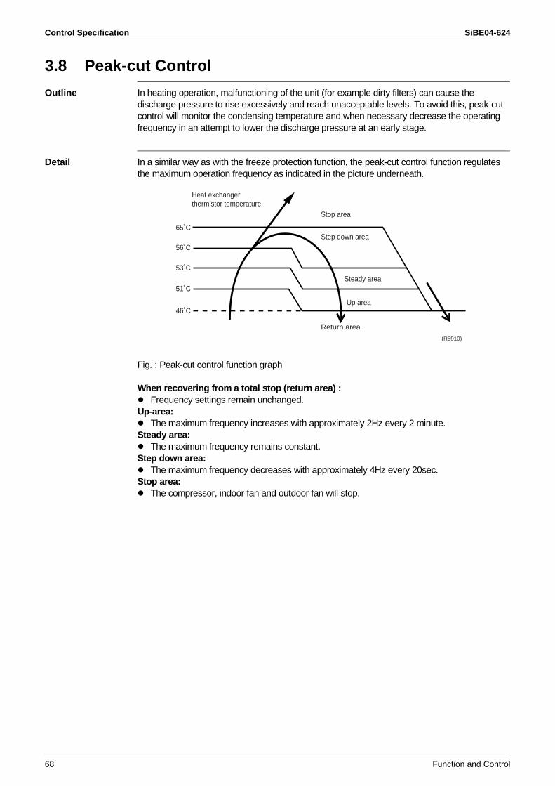
Control Specification SiBE04-624
68 Function and Control
3.8 Peak-cut Control
Outline In heating operation, malfunctioning of the unit (for example dirty filters) can cause the discharge pressure to rise excessively and reach unacceptable levels. To avoid this, peak-cut control will monitor the condensing temperature and when necessary decrease the operating frequency in an attempt to lower the discharge pressure at an early stage.
Detail In a similar way as with the freeze protection function, the peak-cut control function regulates the maximum operation frequency as indicated in the picture underneath.
Fig. : Peak-cut control function graph
When recovering from a total stop (return area) : Frequency settings remain unchanged.
Up-area:The maximum frequency increases with approximately 2Hz every 2 minute.
Steady area:The maximum frequency remains constant.
Step down area:The maximum frequency decreases with approximately 4Hz every 20sec.
Stop area:The compressor, indoor fan and outdoor fan will stop.
Heat exchangerthermistor temperature
65˚C
56˚C
53˚C
51˚C
46˚C
Stop area
Step down area
Steady area
Up area
Return area
(R5910)
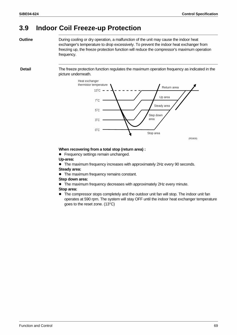
SiBE04-624 Control Specification
Function and Control 69
3.9 Indoor Coil Freeze-up Protection
Outline During cooling or dry operation, a malfunction of the unit may cause the indoor heat exchanger's temperature to drop excessively. To prevent the indoor heat exchanger from freezing up, the freeze protection function will reduce the compressor's maximum operation frequency.
Detail The freeze protection function regulates the maximum operation frequency as indicated in the picture underneath.
When recovering from a total stop (return area) : Frequency settings remain unchanged.
Up-area:The maximum frequency increases with approximately 2Hz every 90 seconds.
Steady area:The maximum frequency remains constant.
Step down area:The maximum frequency decreases with approximately 2Hz every minute.
Stop area:The compressor stops completely and the outdoor unit fan will stop. The indoor unit fan operates at 590 rpm. The system will stay OFF until the indoor heat exchanger temperature goes to the reset zone. (13°C)
(R5909)
Heat exchangerthermistor temperature
13˚C
7˚C
5˚C
3˚C
0˚CStop area
Step down area
Steady area
Up area
Return area
Control Specification SiBE04-624
70 Function and Control
3.10 Dew Prevention
Outline Cooling the air around us means that the air is dehumidified (condensation of water on the coil). But because the air is cooled down, less water can be absorbed by the air and as a consequence the relative humidity of the air rises. When the relative humidity of the outlet air nears 100%, you will have water being blown in. To prevent this from happening, the unit will, under certain circumstances, change its target evaporating temperature and the frequency of the compressor. Normally speaking, even under these conditions (dew prevention safety active), the room should still be cooled down, only slower. Of course, if the indoor unit is rather on the small size in comparison to the heat load, this will not be the case and capacity shortage complaints will follow.
Detail 1. Conditions for initiating the dew prevention function. Operation mode is in cooling/dry. Compressor is running.
When the temperature of indoor heat exchanger is lower than the target temperature of heat exchanger, the compressor frequency will be pulled down by 2 Hz in every minute. The target temperature of heat exchanger is calculated by the following formula with using the room temperature and indoor humidity.
Target temp. of heat exchanger = 0.94 x room temp. + 0.27 x indoor humidity – 32.5
2. Conditions for ending the dew prevention function Operation mode is not in cooling/dry. Compressor is not running.
SiBE04-624 Control Specification
Function and Control 71
3.11 Liquid Compression Protection 2
Outline The function will ensure a pressure differential between the high pressure and the low pressure. This is required when cooling with low outdoor ambient temperature because HP gets weak and you will have small capacity and a high power input.The compressor stops according to the conditions of the outdoor ambient temperature and the outdoor heat exchanger temperature.
Details Outdoor ambient temperature and outdoor heat exchanger temperatureCooling or Dry modeCompressor onOutdoor ambient < 10°COutdoor heat exchanger < 17°C
If all of these are fulfilled for 11 minutes, the compressor is stopped, the system is reset and restarted after 3 minutes.
Outdoor ambient temperature onlyCooling or Dry modeNot in forced cooling modeOutdoor ambient < 0°C
If all of these are fulfilled , the compressor is stopped, the system resumes operation when the outdoor ambient temperature rises above 0°C.

Control Specification SiBE04-624
72 Function and Control
3.12 Discharge Pipe Temperature Control
Outline Overheating has a negative influence on the operating lifetime of a compressor. That's why this function will limit the maximum operating frequency of the compressor if deemed necessary.
Detail Discharge pipe temperature (°C)
Correction value (a) = correction value by operation frequency (b) +correction value by outdoor temperature (c)
Correction value by operation frequency (b)
Correction value by outdoor temperature (c)
When recovering from a total stop (return area) : Frequency settings remain unchanged.
Up-area:The maximum frequency increases with 2Hz / 60 seconds
Steady area:Present frequency is maximum frequency.
Step down area:The maximum frequency decreases with 4Hz per 30 seconds.
Stop area:The compressor stops and will only restart when the sensor senses a temperature below set point.
108 - correction value (a)
118 - correction value (a)
103 - correction value (a)
97 - correction value (a)
85 - correction value (a)
Stop
Step down
Steady
Up
Return
(R5913)
Correction value (b) = 8 deg
Correction value (b) = 0 deg
Correction value (b) = 12 deg
50rps
35rps
45rps
30rps
Operation frequency
(R5914)
Correction value (c) = 0 deg
Correction value (c) = 7 deg
-10˚C
-9˚COutdoor temperature
(R5915)
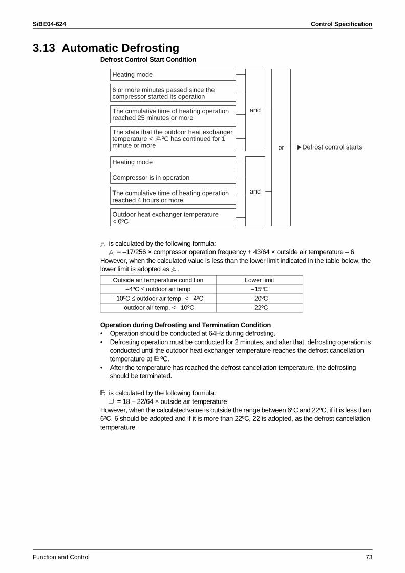
SiBE04-624 Control Specification
Function and Control 73
3.13 Automatic DefrostingDefrost Control Start Condition
is calculated by the following formula: = –17/256 × compressor operation frequency + 43/64 × outside air temperature – 6
However, when the calculated value is less than the lower limit indicated in the table below, the lower limit is adopted as .
Operation during Defrosting and Termination Condition• Operation should be conducted at 64Hz during defrosting.• Defrosting operation must be conducted for 2 minutes, and after that, defrosting operation is
conducted until the outdoor heat exchanger temperature reaches the defrost cancellation temperature at ºC.
• After the temperature has reached the defrost cancellation temperature, the defrosting should be terminated.
is calculated by the following formula: = 18 – 22/64 × outside air temperature
However, when the calculated value is outside the range between 6ºC and 22ºC, if it is less than 6ºC, 6 should be adopted and if it is more than 22ºC, 22 is adopted, as the defrost cancellation temperature.
Outside air temperature condition Lower limit
–4ºC ≤ outdoor air temp –15ºC
–10ºC ≤ outdoor air temp. < –4ºC –20ºC
outdoor air temp. < –10ºC –22ºC
Defrost control starts
and
or
Heating mode
and
Heating mode
Compressor is in operation
6 or more minutes passed since the compressor started its operation
The cumulative time of heating operation reached 25 minutes or more
The cumulative time of heating operation reached 4 hours or more
Outdoor heat exchanger temperature < 0ºC
The state that the outdoor heat exchanger temperature < ºC has continued for 1 minute or more
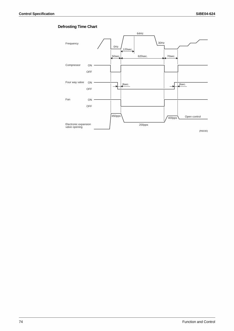
Control Specification SiBE04-624
74 Function and Control
Defrosting Time Chart
ON
OFF
Frequency
Compressor
ON
OFF
Four way valve
ON
OFF
Fan
Electronic expansionvalve opening
0Hz30Hz
64Hz
120sec.
50sec.
450pps400pps Open control
200pps
8sec. 8sec.
70sec.620sec.
(R6030)
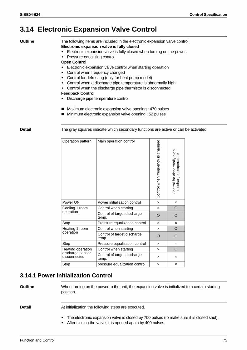
SiBE04-624 Control Specification
Function and Control 75
3.14 Electronic Expansion Valve Control
Outline The following items are included in the electronic expansion valve control.Electronic expansion valve is fully closed
Electronic expansion valve is fully closed when turning on the power.Pressure equalizing control
Open ControlElectronic expansion valve control when starting operationControl when frequency changedControl for defrosting (only for heat pump model)Control when a discharge pipe temperature is abnormally highControl when the discharge pipe thermistor is disconnected
Feedback ControlDischarge pipe temperature control
Maximum electronic expansion valve opening : 470 pulsesMinimum electronic expansion valve opening : 52 pulses
Detail The gray squares indicate which secondary functions are active or can be activated.
3.14.1 Power Initialization Control
Outline When turning on the power to the unit, the expansion valve is initialized to a certain starting position.
Detail At initialization the following steps are executed.
The electronic expansion valve is closed by 700 pulses (to make sure it is closed shut). After closing the valve, it is opened again by 400 pulses.
Operation pattern Main operation control
Con
trol
whe
n fr
eque
ncy
is c
hang
ed
Con
trol
for
abno
rmal
ly h
igh
disc
harg
e te
mpe
ratu
re
Power ON Power initialization control × ×
Cooling 1 room operation
Control when starting ×
Control of target discharge temp.
Stop Pressure equalization control × ×
Heating 1 room operation
Control when starting ×
Control of target discharge temp.
Stop Pressure equalization control × ×
Heating operationdischarge sensor disconnected
Control when starting ×
Control of target discharge temp. × ×
Stop pressure equalization control × ×
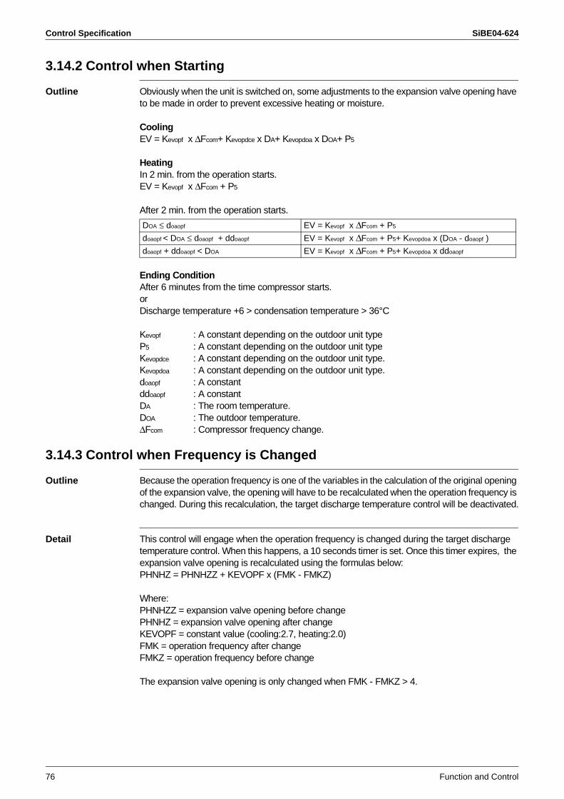
Control Specification SiBE04-624
76 Function and Control
3.14.2 Control when Starting
Outline Obviously when the unit is switched on, some adjustments to the expansion valve opening have to be made in order to prevent excessive heating or moisture.
CoolingEV = Kevopf x ∆Fcom+ Kevopdce x DA+ Kevopdoa x DOA+ P5
HeatingIn 2 min. from the operation starts.EV = Kevopf x ∆Fcom + P5
After 2 min. from the operation starts.
Ending ConditionAfter 6 minutes from the time compressor starts.orDischarge temperature +6 > condensation temperature > 36°C
Kevopf : A constant depending on the outdoor unit type P5 : A constant depending on the outdoor unit type Kevopdce : A constant depending on the outdoor unit type.Kevopdoa : A constant depending on the outdoor unit type.doaopf : A constantddoaopf : A constant DA : The room temperature.DOA : The outdoor temperature.∆Fcom : Compressor frequency change.
3.14.3 Control when Frequency is Changed
Outline Because the operation frequency is one of the variables in the calculation of the original opening of the expansion valve, the opening will have to be recalculated when the operation frequency is changed. During this recalculation, the target discharge temperature control will be deactivated.
Detail This control will engage when the operation frequency is changed during the target discharge temperature control. When this happens, a 10 seconds timer is set. Once this timer expires, the expansion valve opening is recalculated using the formulas below:PHNHZ = PHNHZZ + KEVOPF x (FMK - FMKZ)
Where:PHNHZZ = expansion valve opening before changePHNHZ = expansion valve opening after changeKEVOPF = constant value (cooling:2.7, heating:2.0)FMK = operation frequency after changeFMKZ = operation frequency before change
The expansion valve opening is only changed when FMK - FMKZ > 4.
DOA ≤ doaopf EV = Kevopf x ∆Fcom + P5
doaopf < DOA ≤ doaopf + ddoaopf EV = Kevopf x ∆Fcom + P5+ Kevopdoa x (DOA - doaopf )
doaopf + ddoaopf < DOA EV = Kevopf x ∆Fcom + P5+ Kevopdoa x ddoaopf
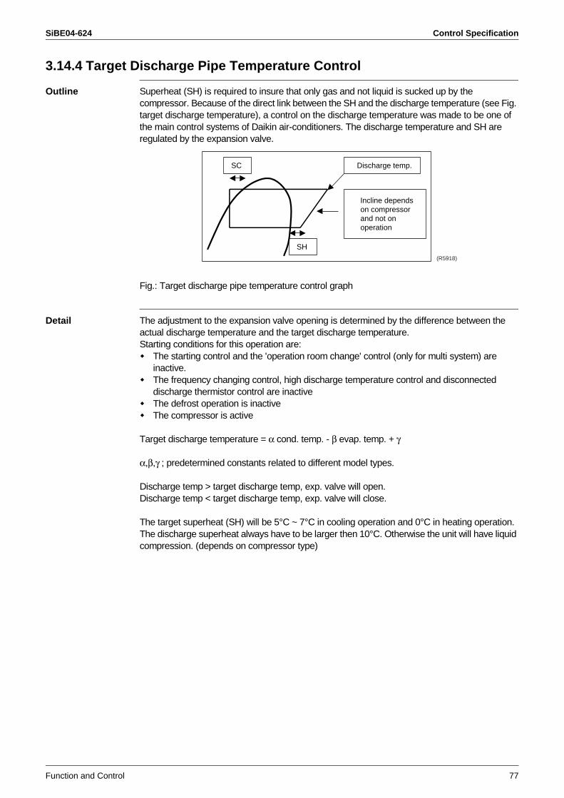
SiBE04-624 Control Specification
Function and Control 77
3.14.4 Target Discharge Pipe Temperature Control
Outline Superheat (SH) is required to insure that only gas and not liquid is sucked up by the compressor. Because of the direct link between the SH and the discharge temperature (see Fig. target discharge temperature), a control on the discharge temperature was made to be one of the main control systems of Daikin air-conditioners. The discharge temperature and SH are regulated by the expansion valve.
Fig.: Target discharge pipe temperature control graph
Detail The adjustment to the expansion valve opening is determined by the difference between the actual discharge temperature and the target discharge temperature.Starting conditions for this operation are:
The starting control and the 'operation room change' control (only for multi system) are inactive.The frequency changing control, high discharge temperature control and disconnected discharge thermistor control are inactiveThe defrost operation is inactiveThe compressor is active
Target discharge temperature = α cond. temp. - β evap. temp. + γ
α,β,γ ; predetermined constants related to different model types.
Discharge temp > target discharge temp, exp. valve will open.Discharge temp < target discharge temp, exp. valve will close.
The target superheat (SH) will be 5°C ~ 7°C in cooling operation and 0°C in heating operation. The discharge superheat always have to be larger then 10°C. Otherwise the unit will have liquid compression. (depends on compressor type)
SC
SH
Discharge temp.
Incline depends on compressor and not on operation
(R5918)
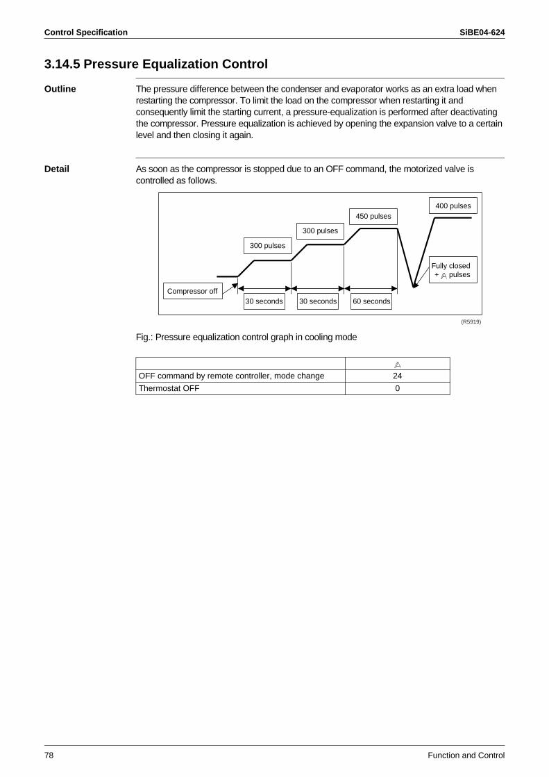
Control Specification SiBE04-624
78 Function and Control
3.14.5 Pressure Equalization Control
Outline The pressure difference between the condenser and evaporator works as an extra load when restarting the compressor. To limit the load on the compressor when restarting it and consequently limit the starting current, a pressure-equalization is performed after deactivating the compressor. Pressure equalization is achieved by opening the expansion valve to a certain level and then closing it again.
Detail As soon as the compressor is stopped due to an OFF command, the motorized valve is controlled as follows.
Fig.: Pressure equalization control graph in cooling mode
OFF command by remote controller, mode change 24
Thermostat OFF 0
300 pulses
300 pulses
30 seconds 30 seconds 60 seconds
450 pulses400 pulses
Fully closed+ pulses
Compressor off
(R5919)
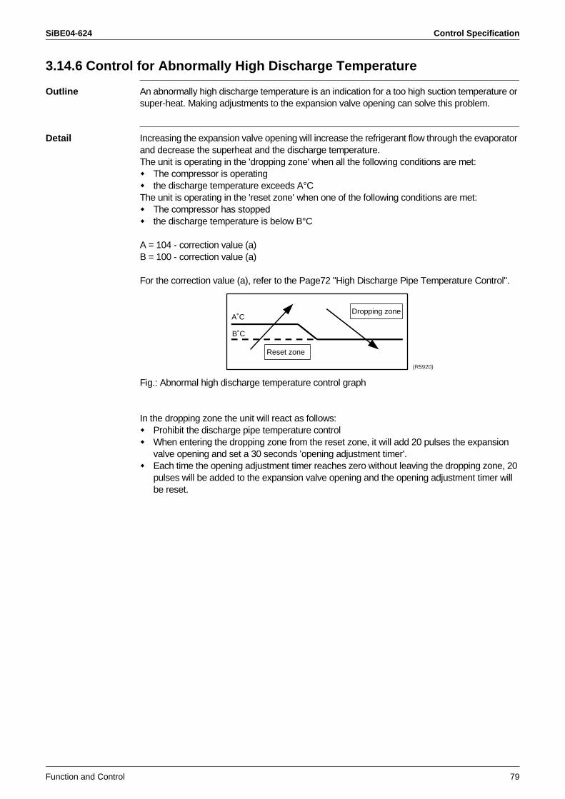
SiBE04-624 Control Specification
Function and Control 79
3.14.6 Control for Abnormally High Discharge Temperature
Outline An abnormally high discharge temperature is an indication for a too high suction temperature or super-heat. Making adjustments to the expansion valve opening can solve this problem.
Detail Increasing the expansion valve opening will increase the refrigerant flow through the evaporator and decrease the superheat and the discharge temperature.The unit is operating in the 'dropping zone' when all the following conditions are met:
The compressor is operatingthe discharge temperature exceeds A°C
The unit is operating in the 'reset zone' when one of the following conditions are met:The compressor has stoppedthe discharge temperature is below B°C
A = 104 - correction value (a)B = 100 - correction value (a)
For the correction value (a), refer to the Page72 "High Discharge Pipe Temperature Control".
Fig.: Abnormal high discharge temperature control graph
In the dropping zone the unit will react as follows:Prohibit the discharge pipe temperature controlWhen entering the dropping zone from the reset zone, it will add 20 pulses the expansion valve opening and set a 30 seconds 'opening adjustment timer'.Each time the opening adjustment timer reaches zero without leaving the dropping zone, 20 pulses will be added to the expansion valve opening and the opening adjustment timer will be reset.
A˚C
B˚C
Reset zone
Dropping zone
(R5920)
Control Specification SiBE04-624
80 Function and Control
SiBE04-624
System Configuration 81
Part 5System Configuration
1. Installation Manual ................................................................................821.1 Indoor Units ............................................................................................821.2 Outdoor Units .........................................................................................96
2. System Configuration..........................................................................1063. Instruction............................................................................................107
3.1 Safety Precautions ...............................................................................1073.2 Names and Functions of Parts .............................................................1083.3 Preparation before Operation...............................................................1103.4 Cooling · “SARARA” DRYING Operation .............................................1123.5 Heating · “URURU” HUMIDIFYING Operation .....................................1133.6 AUTO / MOISTURIZING Operation .....................................................1143.7 Adjusting Airflow Direction · Comfort Airflow Mode · Cooling Breeze ·
Airflow Rate ..........................................................................................1153.8 FLASH STREAMER AIR PURIFYING · FRESH AIR SUPPLY
VENTILATION Operation / HOME LEAVE VENTILATION .................1163.9 TIMER Operation .................................................................................1173.10 COMFORT SLEEP / POWERFUL Operation ......................................1183.11 SET UP ................................................................................................1193.12 MOLD PROOF Operation ....................................................................1203.13 MOLD SHOCK Operation / INFORMATION DISPLAY ........................1213.14 Care and Cleaning ...............................................................................1223.15 Troubleshooting....................................................................................130
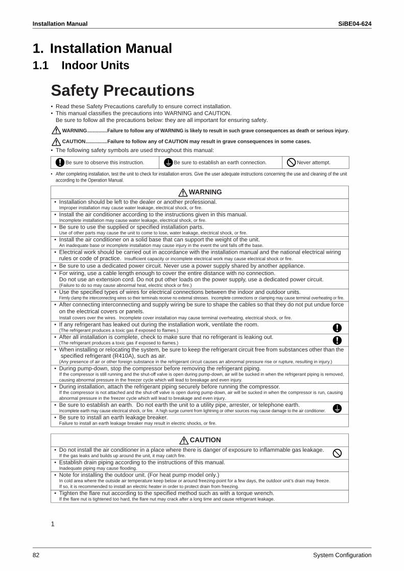
Installation Manual SiBE04-624
82 System Configuration
1. Installation Manual1.1 Indoor Units
1
Safety Precautions• Read these Safety Precautions carefully to ensure correct installation.• This manual classifies the precautions into WARNING and CAUTION.
Be sure to follow all the precautions below: they are all important for ensuring safety.
WARNING...............Failure to follow any of WARNING is likely to result in such grave consequences as death or serious injury.
CAUTION...............Failure to follow any of CAUTION may result in grave consequences in some cases.
• The following safety symbols are used throughout this manual:
• After completing installation, test the unit to check for installation errors. Give the user adequate instructions concerning the use and cleaning of the unit according to the Operation Manual.
Be sure to observe this instruction. Be sure to establish an earth connection. Never attempt.
WARNING• Installation should be left to the dealer or another professional.
Improper installation may cause water leakage, electrical shock, or fire.
• Install the air conditioner according to the instructions given in this manual.Incomplete installation may cause water leakage, electrical shock, or fire.
• Be sure to use the supplied or specified installation parts.Use of other parts may cause the unit to come to lose, water leakage, electrical shock, or fire.
• Install the air conditioner on a solid base that can support the weight of the unit.An inadequate base or incomplete installation may cause injury in the event the unit falls off the base.
• Electrical work should be carried out in accordance with the installation manual and the national electrical wiringrules or code of practice. Insufficient capacity or incomplete electrical work may cause electrical shock or fire.
• Be sure to use a dedicated power circuit. Never use a power supply shared by another appliance.• For wiring, use a cable length enough to cover the entire distance with no connection.
Do not use an extension cord. Do not put other loads on the power supply, use a dedicated power circuit.(Failure to do so may cause abnormal heat, electric shock or fire.)
• Use the specified types of wires for electrical connections between the indoor and outdoor units.Firmly clamp the interconnecting wires so their terminals receive no external stresses. Incomplete connections or clamping may cause terminal overheating or fire.
• After connecting interconnecting and supply wiring be sure to shape the cables so that they do not put undue force on the electrical covers or panels.Install covers over the wires. Incomplete cover installation may cause terminal overheating, electrical shock, or fire.
• If any refrigerant has leaked out during the installation work, ventilate the room.(The refrigerant produces a toxic gas if exposed to flames.)
• After all installation is complete, check to make sure that no refrigerant is leaking out.(The refrigerant produces a toxic gas if exposed to flames.)
• When installing or relocating the system, be sure to keep the refrigerant circuit free from substances other than the specified refrigerant (R410A), such as air.
(Any presence of air or other foreign substance in the refrigerant circuit causes an abnormal pressure rise or rupture, resulting in injury.)
• During pump-down, stop the compressor before removing the refrigerant piping.If the compressor is still running and the shut-off valve is open during pump-down, air will be sucked in when the refrigerant piping is removed, causing abnormal pressure in the freezer cycle which will lead to breakage and even injury.
• During installation, attach the refrigerant piping securely before running the compressor.If the compressor is not attached and the shut-off valve is open during pump-down, air will be sucked in when the compressor is run, causing abnormal pressure in the freezer cycle which will lead to breakage and even injury.
• Be sure to establish an earth. Do not earth the unit to a utility pipe, arrester, or telephone earth.Incomplete earth may cause electrical shock, or fire. A high surge current from lightning or other sources may cause damage to the air conditioner.
• Be sure to install an earth leakage breaker.Failure to install an earth leakage breaker may result in electric shocks, or fire.
CAUTION• Do not install the air conditioner in a place where there is danger of exposure to inflammable gas leakage.
If the gas leaks and builds up around the unit, it may catch fire.
• Establish drain piping according to the instructions of this manual.Inadequate piping may cause flooding.
• Note for installing the outdoor unit. (For heat pump model only.)In cold area where the outside air temperature keep below or around freezing-point for a few days, the outdoor unit’s drain may freeze. If so, it is recommended to install an electric heater in order to protect drain from freezing.
• Tighten the flare nut according to the specified method such as with a torque wrench.If the flare nut is tightened too hard, the flare nut may crack after a long time and cause refrigerant leakage.
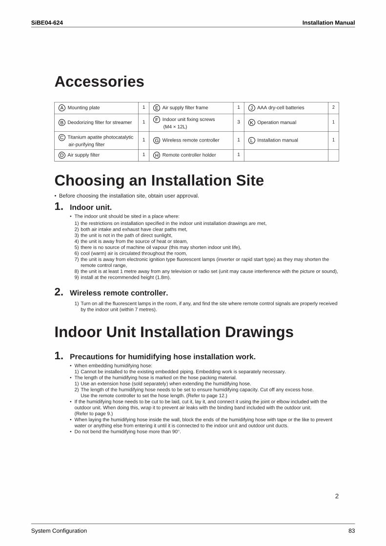
SiBE04-624 Installation Manual
System Configuration 83
2
Accessories
Choosing an Installation Site• Before choosing the installation site, obtain user approval.
1. Indoor unit.• The indoor unit should be sited in a place where:
1) the restrictions on installation specified in the indoor unit installation drawings are met,2) both air intake and exhaust have clear paths met,3) the unit is not in the path of direct sunlight,4) the unit is away from the source of heat or steam,5) there is no source of machine oil vapour (this may shorten indoor unit life),6) cool (warm) air is circulated throughout the room,7) the unit is away from electronic ignition type fluorescent lamps (inverter or rapid start type) as they may shorten the
remote control range,8) the unit is at least 1 metre away from any television or radio set (unit may cause interference with the picture or sound),9) install at the recommended height (1.8m).
2. Wireless remote controller.1) Turn on all the fluorescent lamps in the room, if any, and find the site where remote control signals are properly received
by the indoor unit (within 7 metres).
Indoor Unit Installation Drawings1. Precautions for humidifying hose installation work.
• When embedding humidifying hose:1) Cannot be installed to the existing embedded piping. Embedding work is separately necessary.
• The length of the humidifying hose is marked on the hose packing material.1) Use an extension hose (sold separately) when extending the humidifying hose.2) The length of the humidifying hose needs to be set to ensure humidifying capacity. Cut off any excess hose.
Use the remote controller to set the hose length. (Refer to page 12.)• If the humidifying hose needs to be cut to be laid, cut it, lay it, and connect it using the joint or elbow included with the
outdoor unit. When doing this, wrap it to prevent air leaks with the binding band included with the outdoor unit.(Refer to page 9.)
• When laying the humidifying hose inside the wall, block the ends of the humidifying hose with tape or the like to prevent water or anything else from entering it until it is connected to the indoor unit and outdoor unit ducts.
• Do not bend the humidifying hose more than 90°.
Mounting plate 1 Air supply filter frame 1 AAA dry-cell batteries 2
Deodorizing filter for streamer 1 Indoor unit fixing screws
(M4 × 12L)3 Operation manual 1
Titanium apatite photocatalytic
air-purifying filter1 Wireless remote controller 1 Installation manual 1
Air supply filter 1 Remote controller holder 1
A E J
BF
K
CG L
D H
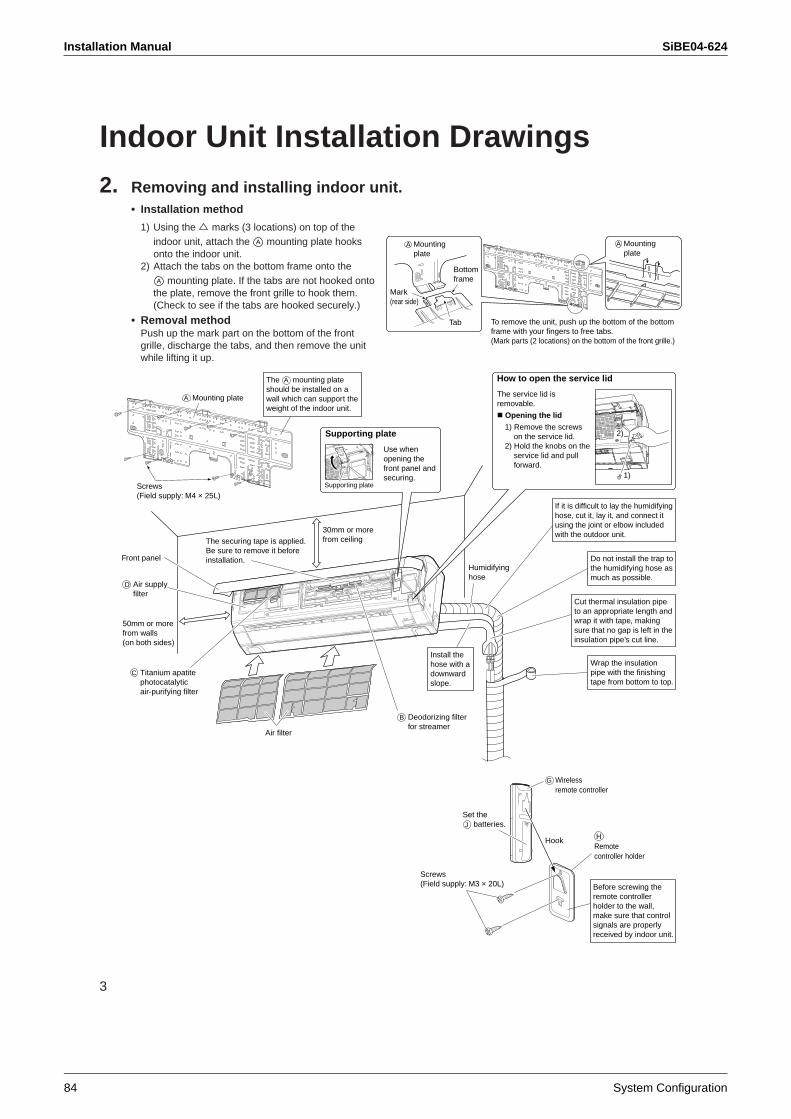
Installation Manual SiBE04-624
84 System Configuration
3
Indoor Unit Installation Drawings2. Removing and installing indoor unit.
• Installation method
1) Using the marks (3 locations) on top of the indoor unit, attach the mounting plate hooks onto the indoor unit.
2) Attach the tabs on the bottom frame onto the mounting plate. If the tabs are not hooked onto
the plate, remove the front grille to hook them. (Check to see if the tabs are hooked securely.)
• Removal method Push up the mark part on the bottom of the front grille, discharge the tabs, and then remove the unit while lifting it up.
Tab
Bottomframe
Mark(rear side)
A Mountingplate
To remove the unit, push up the bottom of the bottom frame with your fingers to free tabs. (Mark parts (2 locations) on the bottom of the front grille.)
A Mountingplate
A
A
HRemotecontroller holder
Screws(Field supply: M3 × 20L)
Air supply filter
D
Wrap the insulation pipe with the finishing tape from bottom to top.
Install the hose with a downward slope.
Do not install the trap to the humidifying hose as much as possible.
If it is difficult to lay the humidifying hose, cut it, lay it, and connect it using the joint or elbow included with the outdoor unit.
Cut thermal insulation pipe to an appropriate length and wrap it with tape, making sure that no gap is left in the insulation pipe’s cut line.
30mm or more from ceiling
50mm or more from walls (on both sides)
Screws (Field supply: M4 × 25L)
A Mounting plate
The mounting plate should be installed on a wall which can support the weight of the indoor unit.
Use when opening the front panel and securing.
Supporting plate
Supporting plate
How to open the service lid
Front panel
Air filter
2)
1)
The service lid is removable.
Opening the lid
1) Remove the screws on the service lid.
2) Hold the knobs on the service lid and pull forward.
Humidifyinghose
Before screwing the remote controller holder to the wall, make sure that control signals are properly received by indoor unit.
C Titanium apatite photocatalyticair-purifying filter
B Deodorizing filter for streamer
Hook
G Wirelessremote controller
Set the batteries.J
The securing tape is applied. Be sure to remove it before installation.
A
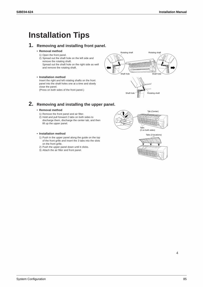
SiBE04-624 Installation Manual
System Configuration 85
4
Installation Tips1. Removing and installing front panel.
• Removal method 1) Open the front panel.2) Spread out the shaft hole on the left side and
remove the rotating shaft. Spread out the shaft hole on the right side as well and remove the rotating shaft.
• Installation method Insert the right and left rotating shafts on the front panel into the shaft holes one at a time and slowly close the panel. (Press on both sides of the front panel.)
2. Removing and installing the upper panel.• Removal method
1) Remove the front panel and air filter.2) Hold and pull forward 2 tabs on both sides to
discharge them, discharge the center tab, and then lift up the upper panel.
• Installation method 1) Push in the upper panel along the guide on the top
of the front grille and insert the 3 tabs into the slots on the front grille.
2) Push the upper panel down until it clicks. 3) Attach the air filter and front panel.
Rotating shaft
Shaft hole
Rotating shaft
Shaft hole
Rotating shaftShaft hole
Tabs (2 on both sides)
Tab (Center)
Tabs (3 locations)
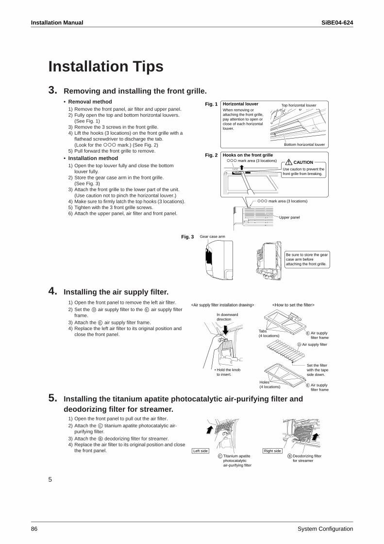
Installation Manual SiBE04-624
86 System Configuration
5
Installation Tips3. Removing and installing the front grille.
• Removal method 1) Remove the front panel, air filter and upper panel.2) Fully open the top and bottom horizontal louvers.
(See Fig. 1)3) Remove the 3 screws in the front grille. 4) Lift the hooks (3 locations) on the front grille with a
flathead screwdriver to discharge the tab. (Look for the mark.) (See Fig. 2)
5) Pull forward the front grille to remove.
• Installation method 1) Open the top louver fully and close the bottom
louver fully.2) Store the gear case arm in the front grille.
(See Fig. 3)3) Attach the front grille to the lower part of the unit.
(Use caution not to pinch the horizontal louver.) 4) Make sure to firmly latch the top hooks (3 locations). 5) Tighten with the 3 front grille screws. 6) Attach the upper panel, air filter and front panel.
4. Installing the air supply filter.1) Open the front panel to remove the left air filter. 2) Set the air supply filter to the air supply filter
frame.3) Attach the air supply filter frame. 4) Replace the left air filter to its original position and
close the front panel.
5. Installing the titanium apatite photocatalytic air-purifying filter and deodorizing filter for streamer.
1) Open the front panel to pull out the air filter. 2) Attach the titanium apatite photocatalytic air-
purifying filter.3) Attach the deodorizing filter for streamer.4) Replace the air filter to its original position and close
the front panel.
Upper panel
mark area (3 locations)
mark area (3 locations)Fig. 2
Fig. 1 Horizontal louver
Hooks on the front grille
When removing or attaching the front grille, pay attention to open or close of each horizontal louver.
Bottom horizontal louver
Top horizontal louver
CAUTION
Use caution to prevent the front grille from breaking.
Gear case arm
Be sure to store the gear case arm before attaching the front grille.
Fig. 3
<How to set the filter><Air supply filter installation drawing>
Tabs (4 locations)
Holes(4 locations)
In downward direction
• Hold the knob to insert.
Set the filter with the tape side down.
D Air supply filter
E Air supply filter frame
E Air supply filter frame
D E
E
Right sideDeodorizing filter for streamer
B
Left sideC Titanium apatite
photocatalyticair-purifying filter
C
B
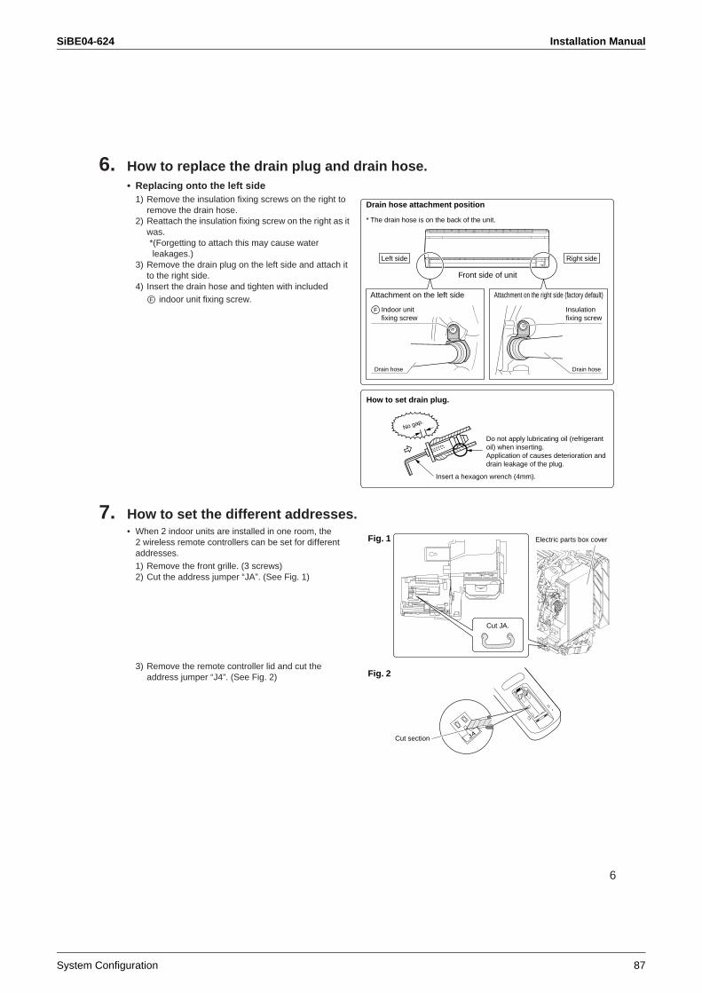
SiBE04-624 Installation Manual
System Configuration 87
6
6. How to replace the drain plug and drain hose.• Replacing onto the left side
1) Remove the insulation fixing screws on the right to remove the drain hose.
2) Reattach the insulation fixing screw on the right as it was.*(Forgetting to attach this may cause water leakages.)
3) Remove the drain plug on the left side and attach it to the right side.
4) Insert the drain hose and tighten with included indoor unit fixing screw.
7. How to set the different addresses.• When 2 indoor units are installed in one room, the
2 wireless remote controllers can be set for different addresses. 1) Remove the front grille. (3 screws)2) Cut the address jumper “JA”. (See Fig. 1)
3) Remove the remote controller lid and cut the address jumper “J4”. (See Fig. 2)
Attachment on the right side (factory default)
Drain hose
Attachment on the left side
* The drain hose is on the back of the unit.
Front side of unit
Drain hose
Drain hose attachment position
Right sideLeft side
Indoor unit fixing screw
F Insulationfixing screw
How to set drain plug.
No gap.
Do not apply lubricating oil (refrigerant oil) when inserting.Application of causes deterioration and drain leakage of the plug.
Insert a hexagon wrench (4mm).
F
Electric parts box cover
Cut JA.
Fig. 1
J4
Fig. 2
Cut section
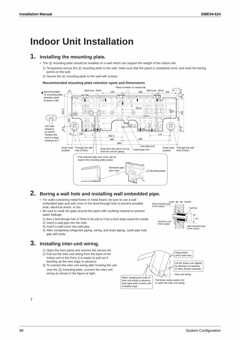
Installation Manual SiBE04-624
88 System Configuration
7
Indoor Unit Installation1. Installing the mounting plate.
• The mounting plate should be installed on a wall which can support the weight of the indoor unit.
1) Temporarily secure the mounting plate to the wall, make sure that the panel is completely level, and mark the boring points on the wall.
2) Secure the mounting plate to the wall with screws.
Recommended mounting plate retention spots and Dimensions
2. Boring a wall hole and installing wall embedded pipe.• For walls containing metal frame or metal board, be sure to use a wall
embedded pipe and wall cover in the feed-through hole to prevent possible heat, electrical shock, or fire.
• Be sure to caulk the gaps around the pipes with caulking material to prevent water leakage.
1) Bore a feed-through hole of 70mm in the wall so it has a down slope toward the outside.2) Insert a wall pipe into the hole.3) Insert a wall cover into wall pipe.4) After completing refrigerant piping, wiring, and drain piping, caulk pipe hole
gap with putty.
3. Installing inter-unit wiring.1) Open the front panel and remove the service lid. 2) Pull out the inter-unit wiring from the back of the
indoor unit to the front. It is easier to pull out if bending up the wire edge in advance.
3) To connect the inter-unit wiring after hooking the unit onto the mounting plate, connect the inter-unit wiring as shown in the figure at right.
A
A
A
(Bolt size : M10)165 285 145
4514
.530
544
.5
260.
544
.5
37
150
100
385 385
170302.5
343.5343.5
393.5
15
890
12
120
120
Removed pipe port cover A Mounting plate
* The removed pipe port cover can be kept in the mounting plate pocket.
Use tape measureas shown. Position the end of a tape measure at ∇.
Liquid pipe endGas pipe end
Keep here the piece cut out from the unit for piping
Through the wall hole φ70mm
Drain hose position
Through the wall hole φ70mm
Drain hose position
φ70 φ70
Place a leveler on raised tab.
Recommended mounting plate retention spots (9 spots in all)
(Bolt size : M10)
A
Inside Outside
Caulking
Wall embedded pipe (Field supply)
Wall hole cover(Field supply)
Wall embedded pipe (Field supply)
φ70
Inter-unit wiring
Hang indoor unit’s hook here.
Lift the indoor unit slightly by placing it on packing or other similar materials.
When stripping the ends of inter-unit wiring in advance, bind right ends of wires with insulation tape.
Pull down using caution not to catch the inter-unit wiring.
A
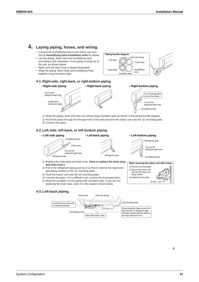
SiBE04-624 Installation Manual
System Configuration 89
8
4. Laying piping, hoses, and wiring.• Connect the humidifying hose to the indoor unit duct.
See 5. Humidifying hose installation work for details. • Lay the piping, drain hose and humidifying hose
according to the orientation of the piping coming out of the unit, as shown below.
• Make sure the drain hose is sloped downward.• Wrap the piping, drain hose and humidifying hose
together using insulation tape.
4-1. Right-side, right-back, or right-bottom piping.
1) Wrap the piping, hose and inter-unit wiring using insulation tape as shown in the piping bundle diagram.2) Put all the pipes through the through-hole in the wall and hook the indoor unit onto the mounting plate.3) Connect the pipes.
4-2. Left-side, left-back, or left-bottom piping.
1) Replace the drain plug and drain hose. (How to replace the drain plug and drain hose.)
2) Pull in the refrigerant piping and lay it so that it matches the liquid and gas piping marked on the mounting plate.
3) Hook the indoor unit onto the mounting plate. 4) Connect the pipes. If it is difficult to do, remove the front panel first.5) Wrap the insulation on the piping with insulation tape. If you are not
replacing the drain hose, store it in the location shown below.
4-3. Left-back piping.
Drain hoseGas pipe
Liquid pipe
Inter-unit wiring
Humidifyinghose
Insulation tape
Piping bundle diagram
Cut out the piping-through hole.
Install with a downward slope.
Cut out the piping-through hole.
• Right-back piping • Right-bottom piping• Right-side piping
Humidifying hose
It is recommended to use the elbow.
A
• Left-back piping • Left-bottom piping• Left-side piping
Cut out the piping-through hole.
Refrigerant pipe
Drain hose
Humidifying hose
Refrigerant pipe
Cut out the piping-through hole.
Humidifying hose
Refrigerant pipe
F M4 × 12L
1) Remove the front grille.
2) Secure the indoor unit with the indoor unit fixing screws.
3) Install the front grille.
When securing the indoor unit with screws
FA
A
Inter-unit wiring
Humidifying hose
Drain hose
Caulk this hole with putty or caulking material.
Bind with plastic tape.
Wrap insulation tape around the bent portion of refrigerant pipe. Overlap at least half the width of the tape with each turn.
Mounting plateA
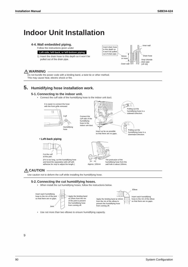
Installation Manual SiBE04-624
90 System Configuration
9
Indoor Unit Installation4-4. Wall embedded piping.
Follow the instructions given under
.
1) Insert the drain hose to this depth so it won’t be pulled out of the drain pipe.
WARNINGDo not bundle the power code with a binding band, a twist tie or other method. This may cause heat, electric shock or fire.
5. Humidifying hose installation work.
5-1. Connecting to the indoor unit. • Connect the cuff side of the humidifying hose to the indoor unit duct.
CAUTIONUse caution not to deform the cuff while installing the humidifying hose.
5-2. Connecting the cut humidifying hoses.• When install the cut humidifying hoses, follow the instructions below.
• Use not more than two elbows to ensure humidifying capacity.
Inner wall
Vinyl chloride drain pipe (VP-30)
Drain hose50mmor more
Outer wall
Insert drain hose to this depth so it won’t be pulled out of drain pipe.
Left-side, left-back, or left-bottom piping
Insert as far as possible so that there are no gaps.
Cut the cuff at this part.
• Left-back piping
It is easier to connect the hose with the front grille removed.
Cuff
Humidifyinghose
Connect the cuff side of the humidifyinghose to the indoor unit duct.
The protrusion of the humidifying hose from the wall hole is about 100mm.
(If it is too long, cut the humidifying hose and bond the separately sold cuff with adhesive for vinyl to adjust the length.)
Pulling out the humidifying hose in a downward direction.
Pulling out the humidifying hose in a sideward direction.
Approx. 100mm
Apply the binding band at 10mm from the rim of the joint to prevent the humidifying hose from coming off.
Insert each humidifying hose to the rim of the joint so that there are no gaps. Apply the binding band at 10mm
from the rim of the elbow to prevent the humidifying hose from coming off.
Insert each humidifying hose to the rim of the elbow so that there are no gaps.
Elbow
Joint
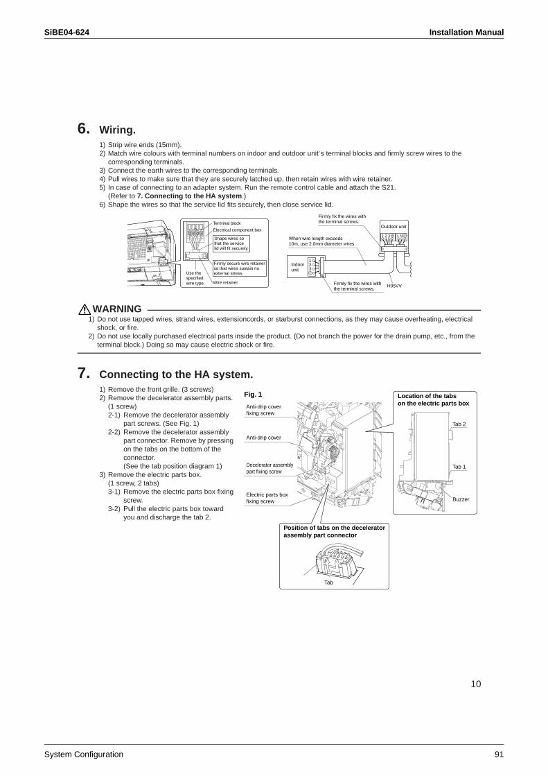
SiBE04-624 Installation Manual
System Configuration 91
10
6. Wiring.1) Strip wire ends (15mm).2) Match wire colours with terminal numbers on indoor and outdoor unit’s terminal blocks and firmly screw wires to the
corresponding terminals.3) Connect the earth wires to the corresponding terminals.4) Pull wires to make sure that they are securely latched up, then retain wires with wire retainer.5) In case of connecting to an adapter system. Run the remote control cable and attach the S21.
(Refer to 7. Connecting to the HA system.)6) Shape the wires so that the service lid fits securely, then close service lid.
WARNING1) Do not use tapped wires, strand wires, extensioncords, or starburst connections, as they may cause overheating, electrical
shock, or fire.2) Do not use locally purchased electrical parts inside the product. (Do not branch the power for the drain pump, etc., from the
terminal block.) Doing so may cause electric shock or fire.
7. Connecting to the HA system.1) Remove the front grille. (3 screws) 2) Remove the decelerator assembly parts.
(1 screw)2-1) Remove the decelerator assembly
part screws. (See Fig. 1)2-2) Remove the decelerator assembly
part connector. Remove by pressing on the tabs on the bottom of the connector. (See the tab position diagram 1)
3) Remove the electric parts box. (1 screw, 2 tabs)3-1) Remove the electric parts box fixing
screw.3-2) Pull the electric parts box toward
you and discharge the tab 2.
Shape wires so that the service lid will fit securely.
Terminal block
Electrical component box
Wire retainer
Firmly secure wire retainer so that wires sustain no external stress.Use the
specifiedwire type.
123
1 2 3 L NWhen wire length exceeds 10m, use 2.0mm diameter wires.
H05VV
Firmly fix the wires with the terminal screws.
Outdoor unit
Indoorunit
Firmly fix the wires with the terminal screws.
Fig. 1
Decelerator assembly part fixing screw
Anti-drip cover
Electric parts box fixing screw
Anti-drip cover fixing screw
Position of tabs on the decelerator assembly part connector
Location of the tabs on the electric parts box
Tab
Tab 2
Tab 1
Buzzer
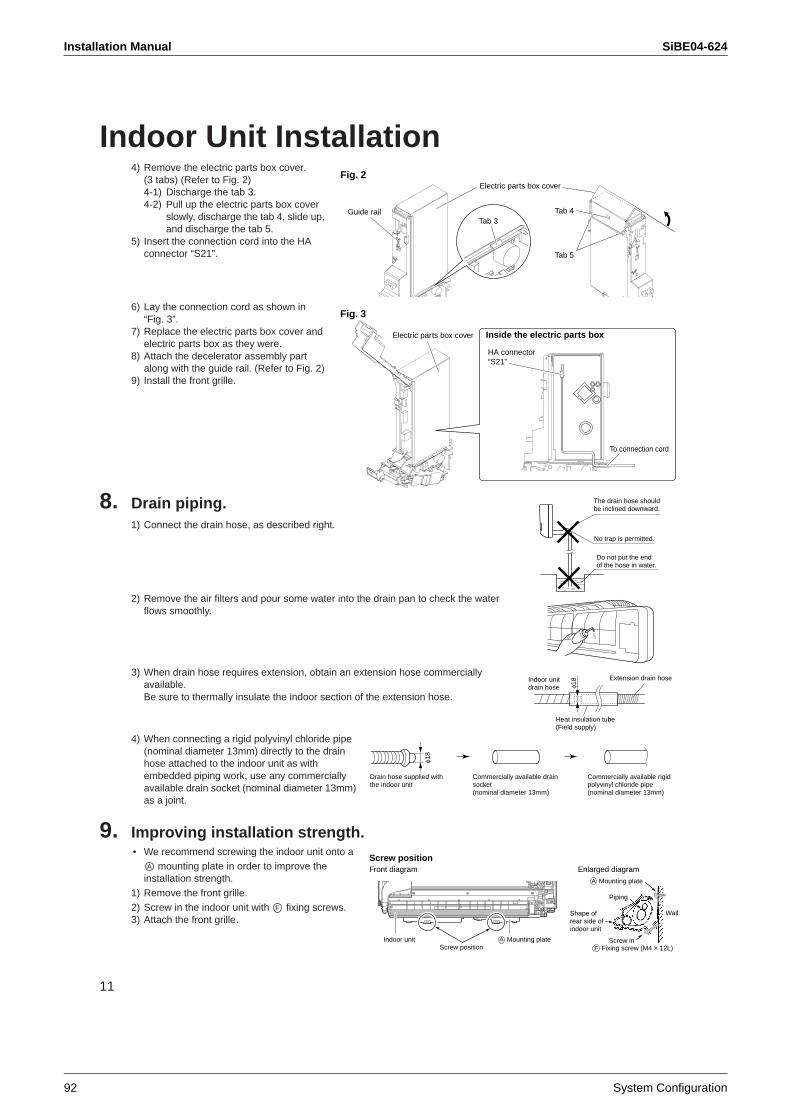
Installation Manual SiBE04-624
92 System Configuration
11
Indoor Unit Installation4) Remove the electric parts box cover.
(3 tabs) (Refer to Fig. 2)4-1) Discharge the tab 3.4-2) Pull up the electric parts box cover
slowly, discharge the tab 4, slide up, and discharge the tab 5.
5) Insert the connection cord into the HA connector “S21”.
6) Lay the connection cord as shown in “Fig. 3”.
7) Replace the electric parts box cover and electric parts box as they were.
8) Attach the decelerator assembly part along with the guide rail. (Refer to Fig. 2)
9) Install the front grille.
8. Drain piping.1) Connect the drain hose, as described right.
2) Remove the air filters and pour some water into the drain pan to check the water flows smoothly.
3) When drain hose requires extension, obtain an extension hose commercially available. Be sure to thermally insulate the indoor section of the extension hose.
4) When connecting a rigid polyvinyl chloride pipe (nominal diameter 13mm) directly to the drain hose attached to the indoor unit as with embedded piping work, use any commercially available drain socket (nominal diameter 13mm) as a joint.
9. Improving installation strength.• We recommend screwing the indoor unit onto a
mounting plate in order to improve the installation strength.
1) Remove the front grille.2) Screw in the indoor unit with fixing screws.3) Attach the front grille.
Tab 3
Electric parts box cover
Guide rail Tab 4
Tab 5
Fig. 2
Inside the electric parts box
Fig. 3
Electric parts box cover
HA connector “S21”
To connection cord
The drain hose should be inclined downward.
No trap is permitted.
Do not put the end of the hose in water.
Indoor unit drain hose φ1
8 Extension drain hose
Heat insulation tube(Field supply)
Drain hose supplied with the indoor unit
Commercially available drain socket (nominal diameter 13mm)
Commercially available rigid polyvinyl chloride pipe(nominal diameter 13mm)
φ18
Shape of rear side of indoor unit
Wall
Piping
Indoor unitScrew position
A Mounting plate
A Mounting plate
Screw inF Fixing screw (M4 × 12L)
Front diagram Enlarged diagramScrew position
A
F
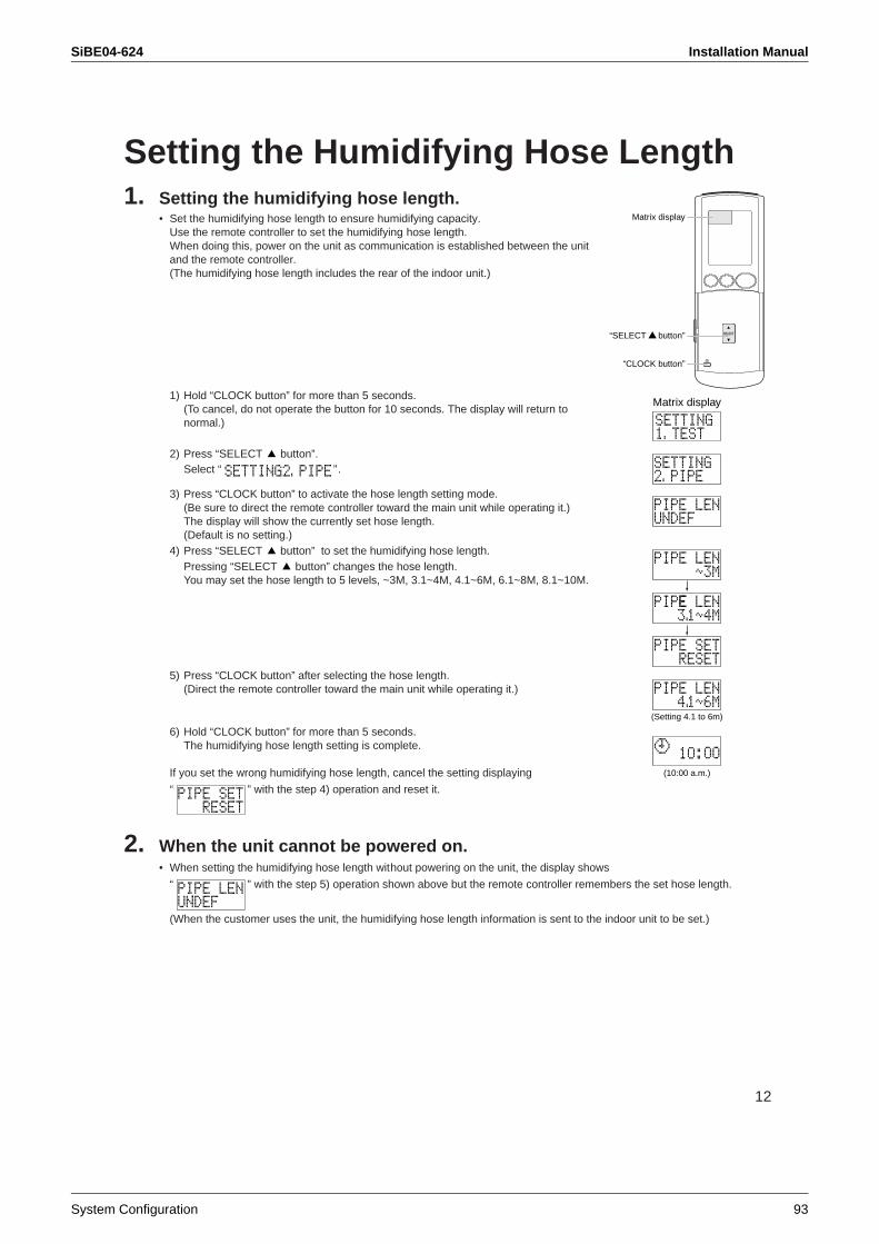
SiBE04-624 Installation Manual
System Configuration 93
12
Setting the Humidifying Hose Length1. Setting the humidifying hose length.
• Set the humidifying hose length to ensure humidifying capacity. Use the remote controller to set the humidifying hose length. When doing this, power on the unit as communication is established between the unit and the remote controller. (The humidifying hose length includes the rear of the indoor unit.)
1) Hold “CLOCK button” for more than 5 seconds. (To cancel, do not operate the button for 10 seconds. The display will return to normal.)
2) Press “SELECT button”. Select “ ”.
3) Press “CLOCK button” to activate the hose length setting mode. (Be sure to direct the remote controller toward the main unit while operating it.)The display will show the currently set hose length. (Default is no setting.)
4) Press “SELECT button” to set the humidifying hose length. Pressing “SELECT button” changes the hose length. You may set the hose length to 5 levels, ~3M, 3.1~4M, 4.1~6M, 6.1~8M, 8.1~10M.
5) Press “CLOCK button” after selecting the hose length. (Direct the remote controller toward the main unit while operating it.)
6) Hold “CLOCK button” for more than 5 seconds. The humidifying hose length setting is complete.
If you set the wrong humidifying hose length, cancel the setting displaying
“ ” with the step 4) operation and reset it.
2. When the unit cannot be powered on.• When setting the humidifying hose length without powering on the unit, the display shows
“ ” with the step 5) operation shown above but the remote controller remembers the set hose length.
(When the customer uses the unit, the humidifying hose length information is sent to the indoor unit to be set.)
“CLOCK button”
Matrix display
“SELECT button”
Matrix display
(Setting 4.1 to 6m)
(10:00 a.m.)
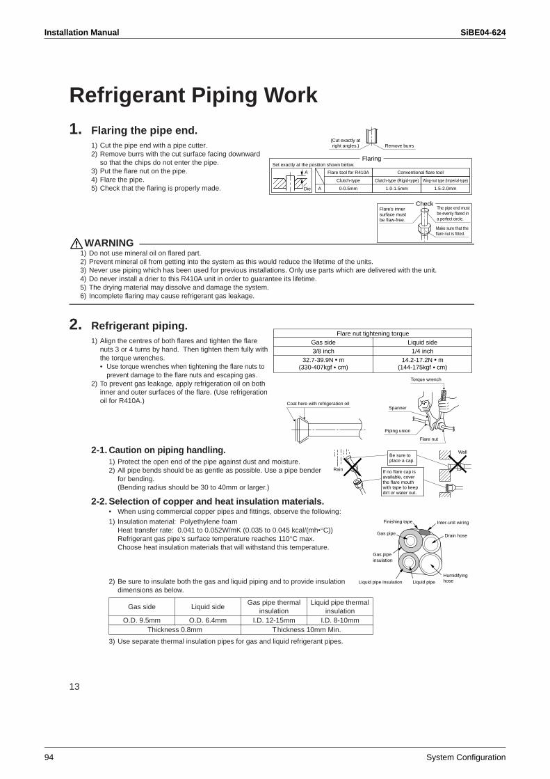
Installation Manual SiBE04-624
94 System Configuration
13
Refrigerant Piping Work1. Flaring the pipe end.
1) Cut the pipe end with a pipe cutter.2) Remove burrs with the cut surface facing downward
so that the chips do not enter the pipe.3) Put the flare nut on the pipe.4) Flare the pipe.5) Check that the flaring is properly made.
WARNING1) Do not use mineral oil on flared part.2) Prevent mineral oil from getting into the system as this would reduce the lifetime of the units.3) Never use piping which has been used for previous installations. Only use parts which are delivered with the unit.4) Do never install a drier to this R410A unit in order to guarantee its lifetime.5) The drying material may dissolve and damage the system.6) Incomplete flaring may cause refrigerant gas leakage.
2. Refrigerant piping.1) Align the centres of both flares and tighten the flare
nuts 3 or 4 turns by hand. Then tighten them fully with the torque wrenches.• Use torque wrenches when tightening the flare nuts to
prevent damage to the flare nuts and escaping gas.2) To prevent gas leakage, apply refrigeration oil on both
inner and outer surfaces of the flare. (Use refrigeration oil for R410A.)
2-1. Caution on piping handling. 1) Protect the open end of the pipe against dust and moisture.2) All pipe bends should be as gentle as possible. Use a pipe bender
for bending. (Bending radius should be 30 to 40mm or larger.)
2-2. Selection of copper and heat insulation materials.• When using commercial copper pipes and fittings, observe the following:
1) Insulation material: Polyethylene foamHeat transfer rate: 0.041 to 0.052W/mK (0.035 to 0.045 kcal/(mh•°C))Refrigerant gas pipe’s surface temperature reaches 110°C max.Choose heat insulation materials that will withstand this temperature.
2) Be sure to insulate both the gas and liquid piping and to provide insulation dimensions as below.
3) Use separate thermal insulation pipes for gas and liquid refrigerant pipes.
Gas side Liquid sideGas pipe thermal
insulationLiquid pipe thermal
insulationO.D. 9.5mm O.D. 6.4mm I.D. 12-15mm I.D. 8-10mm
Thickness 0.8mm Thickness 10mm Min.
Set exactly at the position shown below.
A
Flaring
Die A 0-0.5mm
Clutch-type
Flare tool for R410A
1.0-1.5mm
Clutch-type (Rigid-type)
1.5-2.0mm
Wing-nut type (Imperial-type)
Conventional flare tool
(Cut exactly at right angles.) Remove burrs
CheckFlare’s inner surface must be flaw-free.
The pipe end must be evenly flared in a perfect circle.
Make sure that the flare nut is fitted.
32.7-39.9N m(330-407kgf cm)
14.2-17.2N m(144-175kgf cm)
Flare nut tightening torqueGas side Liquid side3/8 inch 1/4 inch
Coat here with refrigeration oil
Torque wrench
Piping union
Flare nut
Spanner
Wall
If no flare cap is available, cover the flare mouth with tape to keep dirt or water out.
Be sure to place a cap.
Rain
Finishing tape
Liquid pipe insulation
Inter-unit wiring
Gas pipe insulation
Gas pipe
Humidifyinghose
Drain hose
Liquid pipe
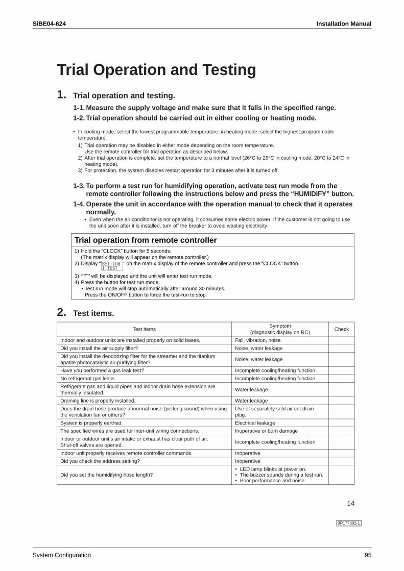
SiBE04-624 Installation Manual
System Configuration 95
14
Trial Operation and Testing1. Trial operation and testing.
1-1. Measure the supply voltage and make sure that it falls in the specified range.
1-2. Trial operation should be carried out in either cooling or heating mode.
• In cooling mode, select the lowest programmable temperature; in heating mode, select the highest programmable temperature.
1) Trial operation may be disabled in either mode depending on the room temperature.Use the remote controller for trial operation as described below.
2) After trial operation is complete, set the temperature to a normal level (26°C to 28°C in cooling mode, 20°C to 24°C in heating mode).
3) For protection, the system disables restart operation for 3 minutes after it is turned off.
1-3. To perform a test run for humidifying operation, activate test run mode from the remote controller following the instructions below and press the “HUMIDIFY” button.
1-4. Operate the unit in accordance with the operation manual to check that it operates normally.
• Even when the air conditioner is not operating, it consumes some electric power. If the customer is not going to use the unit soon after it is installed, turn off the breaker to avoid wasting electricity.
2. Test items.
Test itemsSymptom
(diagnostic display on RC)Check
Indoor and outdoor units are installed properly on solid bases. Fall, vibration, noise
Did you install the air supply filter? Noise, water leakage
Did you install the deodorizing filter for the streamer and the titanium apatite photocatalytic air-purifying filter?
Noise, water leakage
Have you performed a gas leak test? Incomplete cooling/heating function
No refrigerant gas leaks. Incomplete cooling/heating function
Refrigerant gas and liquid pipes and indoor drain hose extension are thermally insulated.
Water leakage
Draining line is properly installed. Water leakage
Does the drain hose produce abnormal noise (perking sound) when using the ventilation fan or others?
Use of separately sold air cut drain plug.
System is properly earthed. Electrical leakage
The specified wires are used for inter-unit wiring connections. Inoperative or burn damage
Indoor or outdoor unit’s air intake or exhaust has clear path of air.Shut-off valves are opened.
Incomplete cooling/heating function
Indoor unit properly receives remote controller commands. Inoperative
Did you check the address setting? Inoperative
Did you set the humidifying hose length?• LED lamp blinks at power on.• The buzzer sounds during a test run.• Poor performance and noise
1) Hold the “CLOCK” button for 5 seconds. (The matrix display will appear on the remote controller.)
2) Display “ ” on the matrix display of the remote controller and press the “CLOCK” button.
3) “ ” will be displayed and the unit will enter test run mode.4) Press the button for test run mode.
• Test run mode will stop automatically after around 30 minutes. Press the ON/OFF button to force the test-run to stop.
Trial operation from remote controller
3P177302-1
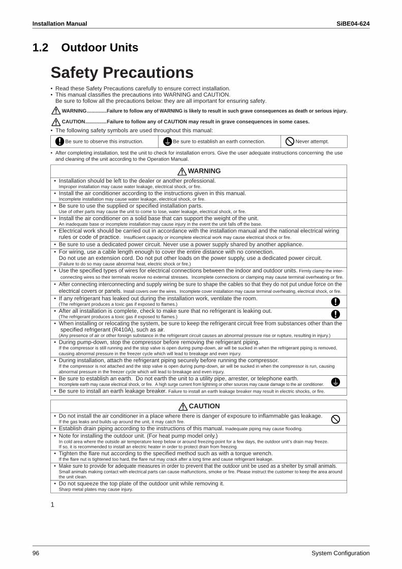
Installation Manual SiBE04-624
96 System Configuration
1.2 Outdoor Units
1
Safety Precautions• Read these Safety Precautions carefully to ensure correct installation.• This manual classifies the precautions into WARNING and CAUTION.
Be sure to follow all the precautions below: they are all important for ensuring safety.
WARNING...............Failure to follow any of WARNING is likely to result in such grave consequences as death or serious injury.
CAUTION...............Failure to follow any of CAUTION may result in grave consequences in some cases.
• The following safety symbols are used throughout this manual:
• After completing installation, test the unit to check for installation errors. Give the user adequate instructions concerning the use and cleaning of the unit according to the Operation Manual.
Be sure to observe this instruction. Be sure to establish an earth connection. Never attempt.
WARNING• Installation should be left to the dealer or another professional.
Improper installation may cause water leakage, electrical shock, or fire.
• Install the air conditioner according to the instructions given in this manual.Incomplete installation may cause water leakage, electrical shock, or fire.
• Be sure to use the supplied or specified installation parts.Use of other parts may cause the unit to come to lose, water leakage, electrical shock, or fire.
• Install the air conditioner on a solid base that can support the weight of the unit.An inadequate base or incomplete installation may cause injury in the event the unit falls off the base.
• Electrical work should be carried out in accordance with the installation manual and the national electrical wiringrules or code of practice. Insufficient capacity or incomplete electrical work may cause electrical shock or fire.
• Be sure to use a dedicated power circuit. Never use a power supply shared by another appliance.• For wiring, use a cable length enough to cover the entire distance with no connection.
Do not use an extension cord. Do not put other loads on the power supply, use a dedicated power circuit.(Failure to do so may cause abnormal heat, electric shock or fire.)
• Use the specified types of wires for electrical connections between the indoor and outdoor units. Firmly clamp the inter-connecting wires so their terminals receive no external stresses. Incomplete connections or clamping may cause terminal overheating or fire.
• After connecting interconnecting and supply wiring be sure to shape the cables so that they do not put undue force on the electrical covers or panels. Install covers over the wires. Incomplete cover installation may cause terminal overheating, electrical shock, or fire.
• If any refrigerant has leaked out during the installation work, ventilate the room.(The refrigerant produces a toxic gas if exposed to flames.)
• After all installation is complete, check to make sure that no refrigerant is leaking out.(The refrigerant produces a toxic gas if exposed to flames.)
• When installing or relocating the system, be sure to keep the refrigerant circuit free from substances other than the specified refrigerant (R410A), such as air.
(Any presence of air or other foreign substance in the refrigerant circuit causes an abnormal pressure rise or rupture, resulting in injury.)
• During pump-down, stop the compressor before removing the refrigerant piping.If the compressor is still running and the stop valve is open during pump-down, air will be sucked in when the refrigerant piping is removed, causing abnormal pressure in the freezer cycle which will lead to breakage and even injury.
• During installation, attach the refrigerant piping securely before running the compressor.If the compressor is not attached and the stop valve is open during pump-down, air will be sucked in when the compressor is run, causing abnormal pressure in the freezer cycle which will lead to breakage and even injury.
• Be sure to establish an earth. Do not earth the unit to a utility pipe, arrester, or telephone earth.Incomplete earth may cause electrical shock, or fire. A high surge current from lightning or other sources may cause damage to the air conditioner.
• Be sure to install an earth leakage breaker. Failure to install an earth leakage breaker may result in electric shocks, or fire.
CAUTION• Do not install the air conditioner in a place where there is danger of exposure to inflammable gas leakage.
If the gas leaks and builds up around the unit, it may catch fire.
• Establish drain piping according to the instructions of this manual. Inadequate piping may cause flooding.
• Note for installing the outdoor unit. (For heat pump model only.)In cold area where the outside air temperature keep below or around freezing-point for a few days, the outdoor unit’s drain may freeze. If so, it is recommended to install an electric heater in order to protect drain from freezing.
• Tighten the flare nut according to the specified method such as with a torque wrench.If the flare nut is tightened too hard, the flare nut may crack after a long time and cause refrigerant leakage.
• Make sure to provide for adequate measures in order to prevent that the outdoor unit be used as a shelter by small animals.Small animals making contact with electrical parts can cause malfunctions, smoke or fire. Please instruct the customer to keep the area around the unit clean.
• Do not squeeze the top plate of the outdoor unit while removing it.Sharp metal plates may cause injury.
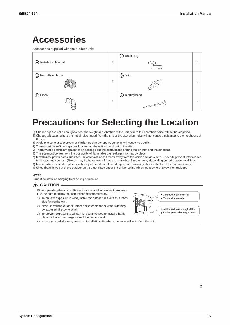
SiBE04-624 Installation Manual
System Configuration 97
2
AccessoriesAccessories supplied with the outdoor unit:
Precautions for Selecting the Location1) Choose a place solid enough to bear the weight and vibration of the unit, where the operation noise will not be amplified.2) Choose a location where the hot air discharged from the unit or the operation noise will not cause a nuisance to the neighbors of
the user.3) Avoid places near a bedroom or similar, so that the operation noise will cause no trouble.4) There must be sufficient spaces for carrying the unit into and out of the site.5) There must be sufficient space for air passage and no obstructions around the air inlet and the air outlet.6) The site must be free from the possibility of flammable gas leakage in a nearby place.7) Install units, power cords and inter-unit cables at least 3 meter away from television and radio sets. This is to prevent interference
to images and sounds. (Noises may be heard even if they are more than 3 meter away depending on radio wave conditions.)8) In coastal areas or other places with salty atmosphere of sulfate gas, corrosion may shorten the life of the air conditioner.9) Since drain flows out of the outdoor unit, do not place under the unit anything which must be kept away from moisture.
NOTECannot be installed hanging from ceiling or stacked.
CAUTIONWhen operating the air conditioner in a low outdoor ambient tempera-ture, be sure to follow the instructions described below.1) To prevent exposure to wind, install the outdoor unit with its suction
side facing the wall.2) Never install the outdoor unit at a site where the suction side may
be exposed directly to wind.3) To prevent exposure to wind, it is recommended to install a baffle
plate on the air discharge side of the outdoor unit.4) In heavy snowfall areas, select an installation site where the snow will not affect the unit.
Installation Manual 1
Drain plug
1
Humidifying hose
1
Joint
1
Elbow
1
Binding band
5
A
B
C D
E F
Construct a large canopy.Construct a pedestal.
Install the unit high enough off the ground to prevent burying in snow.
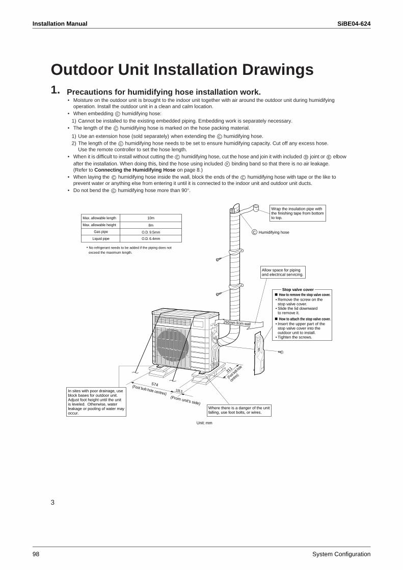
Installation Manual SiBE04-624
98 System Configuration
3
Outdoor Unit Installation Drawings1. Precautions for humidifying hose installation work.
• Moisture on the outdoor unit is brought to the indoor unit together with air around the outdoor unit during humidifying operation. Install the outdoor unit in a clean and calm location.
• When embedding humidifying hose: 1) Cannot be installed to the existing embedded piping. Embedding work is separately necessary.
• The length of the humidifying hose is marked on the hose packing material.
1) Use an extension hose (sold separately) when extending the humidifying hose.2) The length of the humidifying hose needs to be set to ensure humidifying capacity. Cut off any excess hose.
Use the remote controller to set the hose length.• When it is difficult to install without cutting the humidifying hose, cut the hose and join it with included joint or elbow
after the installation. When doing this, bind the hose using included binding band so that there is no air leakage. (Refer to Connecting the Humidifying Hose on page 8.)
• When laying the humidifying hose inside the wall, block the ends of the humidifying hose with tape or the like to prevent water or anything else from entering it until it is connected to the indoor unit and outdoor unit ducts.
• Do not bend the humidifying hose more than 90°.
C
C
C
C
C D E
F
C C
C
Wrap the insulation pipe with the finishing tape from bottom to top.
In sites with poor drainage, use block bases for outdoor unit. Adjust foot height until the unit is leveled. Otherwise, water leakage or pooling of water may occur.
574(Foot bolt-hole centres)(From unit’s side)
Where there is a danger of the unit falling, use foot bolts, or wires.
(Foot bolt-hole
centres)311
250mm from wall
Unit: mm
How to remove the stop valve cover.Remove the screw on the stop valve cover.Slide the lid downward to remove it.
How to attach the stop valve cover.Insert the upper part of the stop valve cover into the outdoor unit to install.Tighten the screws.
Stop valve cover
O.D. 9.5mmGas pipe
Liquid pipe O.D. 6.4mm
8m
10mMax. allowable length
Max. allowable height
* No refrigerant needs to be added if the piping does not exceed the maximum length.
105.5
Humidifying hoseC
Allow space for piping and electrical servicing.
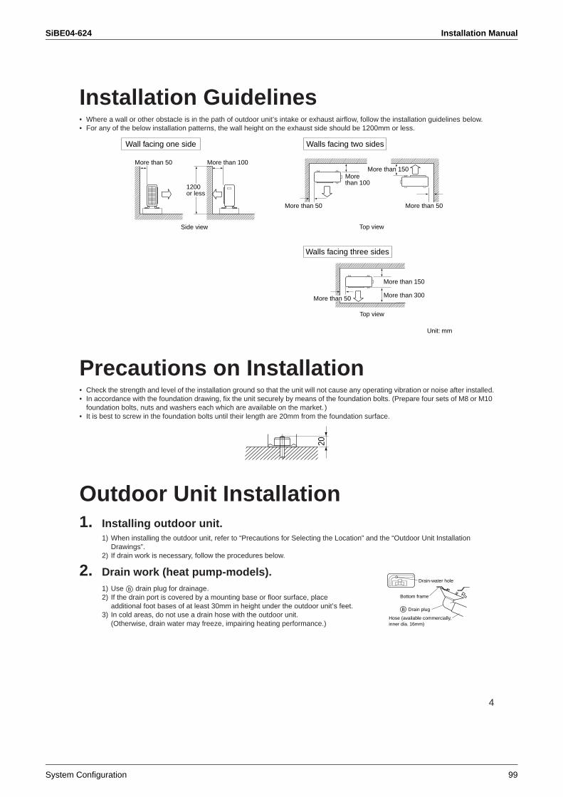
SiBE04-624 Installation Manual
System Configuration 99
4
Installation Guidelines• Where a wall or other obstacle is in the path of outdoor unit’s intake or exhaust airflow, follow the installation guidelines below.• For any of the below installation patterns, the wall height on the exhaust side should be 1200mm or less.
Precautions on Installation• Check the strength and level of the installation ground so that the unit will not cause any operating vibration or noise after installed.• In accordance with the foundation drawing, fix the unit securely by means of the foundation bolts. (Prepare four sets of M8 or M10
foundation bolts, nuts and washers each which are available on the market. )• It is best to screw in the foundation bolts until their length are 20mm from the foundation surface.
Outdoor Unit Installation1. Installing outdoor unit.
1) When installing the outdoor unit, refer to “Precautions for Selecting the Location” and the “Outdoor Unit Installation Drawings”.
2) If drain work is necessary, follow the procedures below.
2. Drain work (heat pump-models).1) Use drain plug for drainage.2) If the drain port is covered by a mounting base or floor surface, place
additional foot bases of at least 30mm in height under the outdoor unit’s feet.3) In cold areas, do not use a drain hose with the outdoor unit.
(Otherwise, drain water may freeze, impairing heating performance.)
Top view
Unit: mm
More than 150
More than 300More than 50
Walls facing three sides
More than 50 More than 50
More than 150
Top view
Morethan 100
Walls facing two sides
More than 50 More than 100
Side view
1200or less
Wall facing one side
20
Drain-water hole
Bottom frame
Hose (available commercially,inner dia. 16mm)
Drain plugB
B
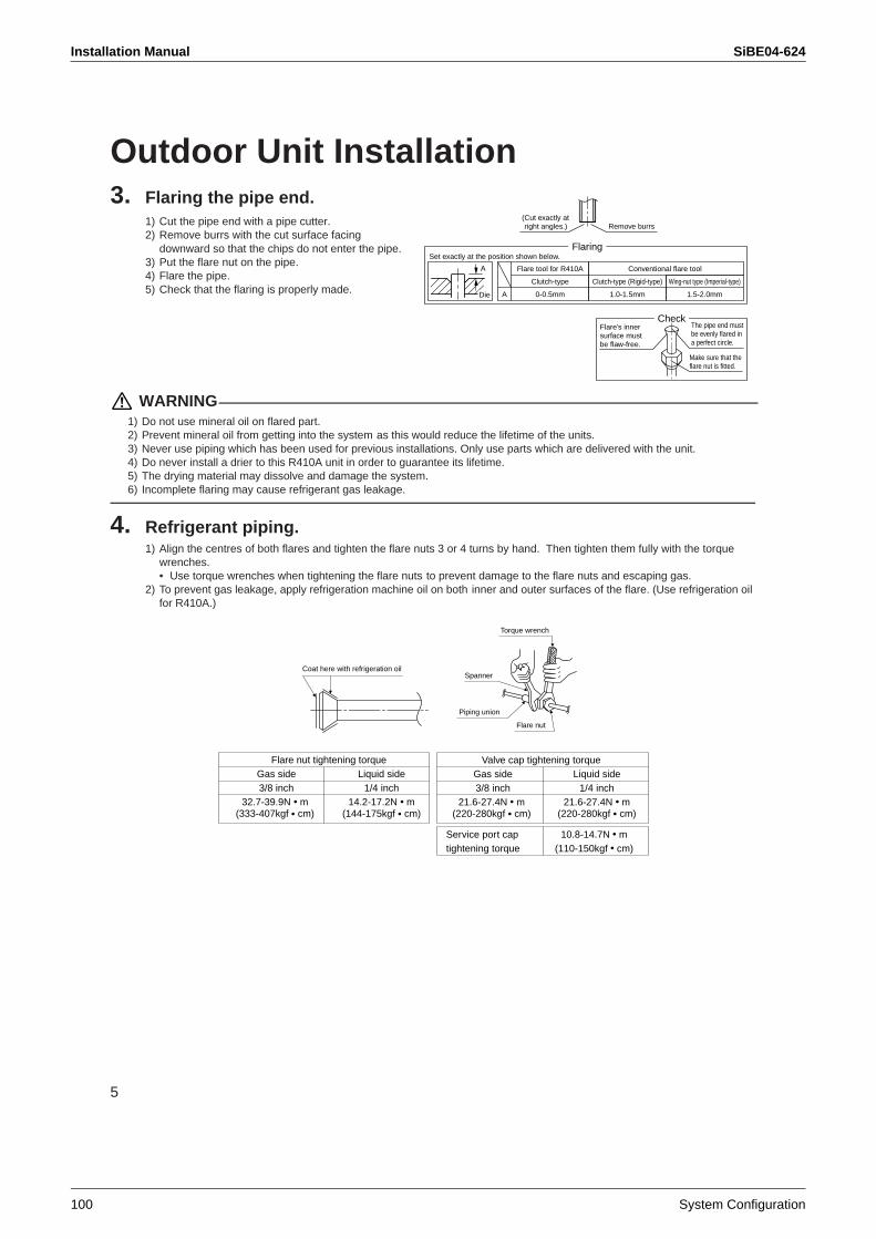
Installation Manual SiBE04-624
100 System Configuration
5
Outdoor Unit Installation3. Flaring the pipe end.
1) Cut the pipe end with a pipe cutter.2) Remove burrs with the cut surface facing
downward so that the chips do not enter the pipe.3) Put the flare nut on the pipe.4) Flare the pipe.5) Check that the flaring is properly made.
WARNING1) Do not use mineral oil on flared part.2) Prevent mineral oil from getting into the system as this would reduce the lifetime of the units.3) Never use piping which has been used for previous installations. Only use parts which are delivered with the unit.4) Do never install a drier to this R410A unit in order to guarantee its lifetime.5) The drying material may dissolve and damage the system.6) Incomplete flaring may cause refrigerant gas leakage.
4. Refrigerant piping.1) Align the centres of both flares and tighten the flare nuts 3 or 4 turns by hand. Then tighten them fully with the torque
wrenches.• Use torque wrenches when tightening the flare nuts to prevent damage to the flare nuts and escaping gas.
2) To prevent gas leakage, apply refrigeration machine oil on both inner and outer surfaces of the flare. (Use refrigeration oilfor R410A.)
(Cut exactly at right angles.) Remove burrs
Set exactly at the position shown below.
A
Flaring
Die
CheckFlare’s inner surface must be flaw-free.
The pipe end must be evenly flared in a perfect circle.
Make sure that the flare nut is fitted.
A 0-0.5mm
Clutch-type
Flare tool for R410A
1.0-1.5mm
Clutch-type (Rigid-type)
1.5-2.0mm
Wing-nut type (Imperial-type)
Conventional flare tool
Coat here with refrigeration oil
Torque wrench
Piping union
Flare nut
Spanner
Flare nut tightening torque Gas side Liquid side 3/8 inch 1/4 inch 32.7-39.9N m 14.2-17.2N m
(333-407kgf cm) (144-175kgf cm)
Valve cap tightening torque Gas side Liquid side 3/8 inch 1/4 inch 21.6-27.4N m 21.6-27.4N m
(220-280kgf cm) (220-280kgf cm)
Service port cap 10.8-14.7N mtightening torque (110-150kgf cm)
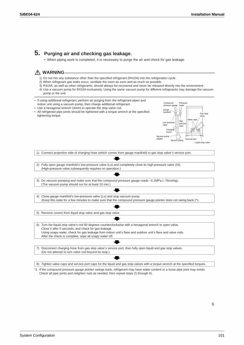
SiBE04-624 Installation Manual
System Configuration 101
6
5. Purging air and checking gas leakage.• When piping work is completed, it is necessary to purge the air and check for gas leakage.
WARNING1) Do not mix any substance other than the specified refrigerant (R410A) into the refrigeration cycle.2) When refrigerant gas leaks occur, ventilate the room as soon and as much as possible.3) R410A, as well as other refrigerants, should always be recovered and never be released directly into the environment .4) Use a vacuum pump for R410A exclusively. Using the same vacuum pump for different refrigerants may damage the vacuum
pump or the unit.
• If using additional refrigerant, perform air purging from the refrigerant pipes and indoor unit using a vacuum pump, then charge additional refrigerant.
• Use a hexagonal wrench (4mm) to operate the stop valve rod.• All refrigerant pipe joints should be tightened with a torque wrench at the specified
tightening torque.
*1. If the compound pressure gauge pointer swings back, refrigerant may have water content or a loose pipe joint may exists. Check all pipe joints and retighten nuts as needed, then repeat steps 2) through 4) .
1) Connect projection side of charging hose (which comes from gauge manifold) to gas stop valve ’s service port.
2) Fully open gauge manifold’s low-pressure valve (Lo) and completely close its high-pressure valve (Hi). (High-pressure valve subsequently requires no operation.)
3) Do vacuum pumping and make sure that the compound pressure gauge reads –0.1MPa (–76cmHg).(The vacuum pump should run for at least 10 min.)
4) Close gauge manifold’s low-pressure valve (Lo) and stop vacuum pump. (Keep this state for a few minutes to make sure that the compound pressure gauge pointer does not swing back.)*1.
5) Remove covers from liquid stop valve and gas stop valve.
6) Turn the liquid stop valve’s rod 90 degrees counterclockwise with a hexagonal wrench to open valve. Close it after 5 seconds, and check for gas leakage.Using soapy water, check for gas leakage from indoor unit’s flare and outdoor unit’s flare and valve rods. After the check is complete, wipe all soapy water off.
7) Disconnect charging hose from gas stop valve’s service port, then fully open liquid and gas stop valves.(Do not attempt to turn valve rod beyond its stop.)
8) Tighten valve caps and service port caps for the liquid and gas stop valves with a torque wrench at the specified torques.
Compoundpressure gauge
Pressuremeter
High-pressurevalve
Low-pressure valve
Vacuum pump adapter
Vacuum pumpService port
Gas stop valve
Valve caps
Liquid stop valve
Charginghoses
Gaugemanifold
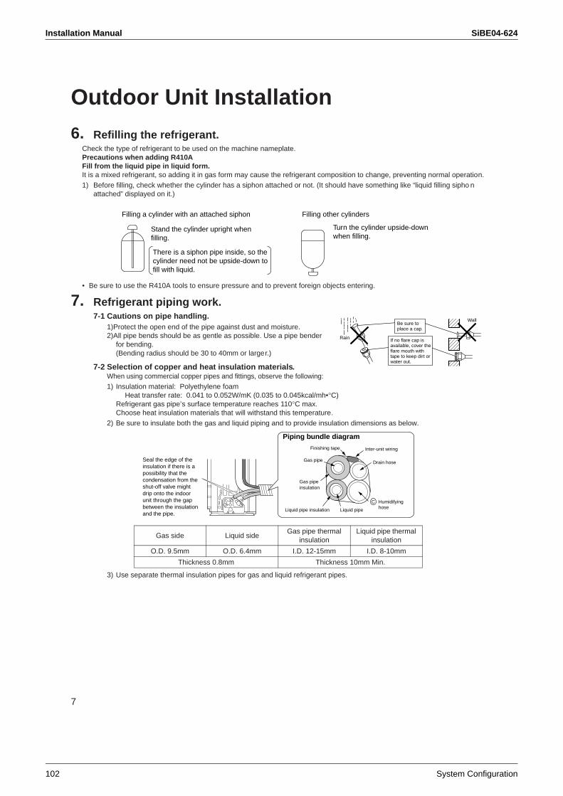
Installation Manual SiBE04-624
102 System Configuration
7
Outdoor Unit Installation
6. Refilling the refrigerant.Check the type of refrigerant to be used on the machine nameplate.Precautions when adding R410AFill from the liquid pipe in liquid form.It is a mixed refrigerant, so adding it in gas form may cause the refrigerant composition to change, preventing normal operation.
1) Before filling, check whether the cylinder has a siphon attached or not. (It should have something like “liquid filling sipho nattached” displayed on it.)
• Be sure to use the R410A tools to ensure pressure and to prevent foreign objects entering.
7. Refrigerant piping work.7-1 Cautions on pipe handling.
1)Protect the open end of the pipe against dust and moisture.2)All pipe bends should be as gentle as possible. Use a pipe bender
for bending.(Bending radius should be 30 to 40mm or larger.)
7-2 Selection of copper and heat insulation materials.When using commercial copper pipes and fittings, observe the following:
1) Insulation material: Polyethylene foam Heat transfer rate: 0.041 to 0.052W/mK (0.035 to 0.045kcal/mh•°C)
Refrigerant gas pipe’s surface temperature reaches 110°C max.Choose heat insulation materials that will withstand this temperature.
2) Be sure to insulate both the gas and liquid piping and to provide insulation dimensions as below.
3) Use separate thermal insulation pipes for gas and liquid refrigerant pipes.
Gas side Liquid sideGas pipe thermal
insulationLiquid pipe thermal
insulation
O.D. 9.5mm O.D. 6.4mm I.D. 12-15mm I.D. 8-10mm
Thickness 0.8mm Thickness 10mm Min.
Filling a cylinder with an attached siphon
Stand the cylinder upright when filling.
There is a siphon pipe inside, so the cylinder need not be upside-down to fill with liquid.
Filling other cylinders
Turn the cylinder upside-down when filling.
Wall
If no flare cap is available, cover the flare mouth with tape to keep dirt or water out.
Be sure to place a cap.
Rain
Piping bundle diagram
Finishing tape
Liquid pipe insulation
Inter-unit wiring
Gas pipe insulation
Gas pipe
Humidifyinghose
C
Drain hose
Liquid pipe
Seal the edge of the insulation if there is a possibility that the condensation from the shut-off valve might drip onto the indoor unit through the gap between the insulation and the pipe.
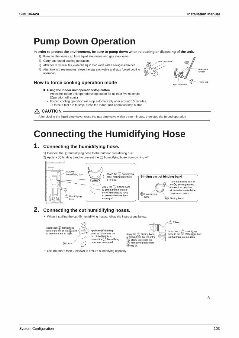
SiBE04-624 Installation Manual
System Configuration 103
8
Pump Down OperationIn order to protect the environment, be sure to pump down when relocating or disposing of the unit.
1) Remove the valve cap from liquid stop valve and gas stop valve.
2) Carry out forced cooling operation.3) After five to ten minutes, close the liquid stop valve with a hexagonal wrench.
4) After two to three minutes, close the gas stop valve and stop forced cooling operation.
How to force cooling operation modeUsing the indoor unit operation/stop button
Press the indoor unit operation/stop button for at least five seconds. (Operation will start.)
• Forced cooling operation will stop automatically after around 15 minutes. To force a test run to stop, press the indoor unit operation/stop button.
CAUTIONAfter closing the liquid stop valve, close the gas stop valve within three minutes, then stop the forced operation .
Connecting the Humidifying Hose1. Connecting the humidifying hose.
1) Connect the humidifying hose to the outdoor humidifying duct. 2) Apply a binding band to prevent the humidifying hose from coming off.
2. Connecting the cut humidifying hoses.• When installing the cut humidifying hoses, follow the instructions below.
• Use not more than 2 elbows to ensure humidifying capacity.
Liquid stop valveValve cap
Hexagonal wrench
CloseGas stop valve
C
F C
Outdoorhumidifying duct
Turn the binding part of the binding band to the outdoor unit side. (It is easier to attach the stop valve cover.)
Binding part of binding bandAttach the humidifying hose, making sure there is no gap.
Apply the binding band at 10mm from the top of the humidifying hose to prevent the hose from coming off.
Humidifyinghose
CHumidifyinghose
C
Binding bandF
C
C
FF
C
Apply the binding band at 10mm from the rim of the joint to prevent the humidifying hose from coming off.
Insert each humidifying hose to the rim of the joint so that there are no gaps. Apply the binding band
at 10mm from the rim of the elbow to prevent the humidifying hose from
coming off.
Insert each humidifying hose to the rim of the elbow so that there are no gaps.
C
C
C
CF
ElbowE
F
JointD
D
D
E
E
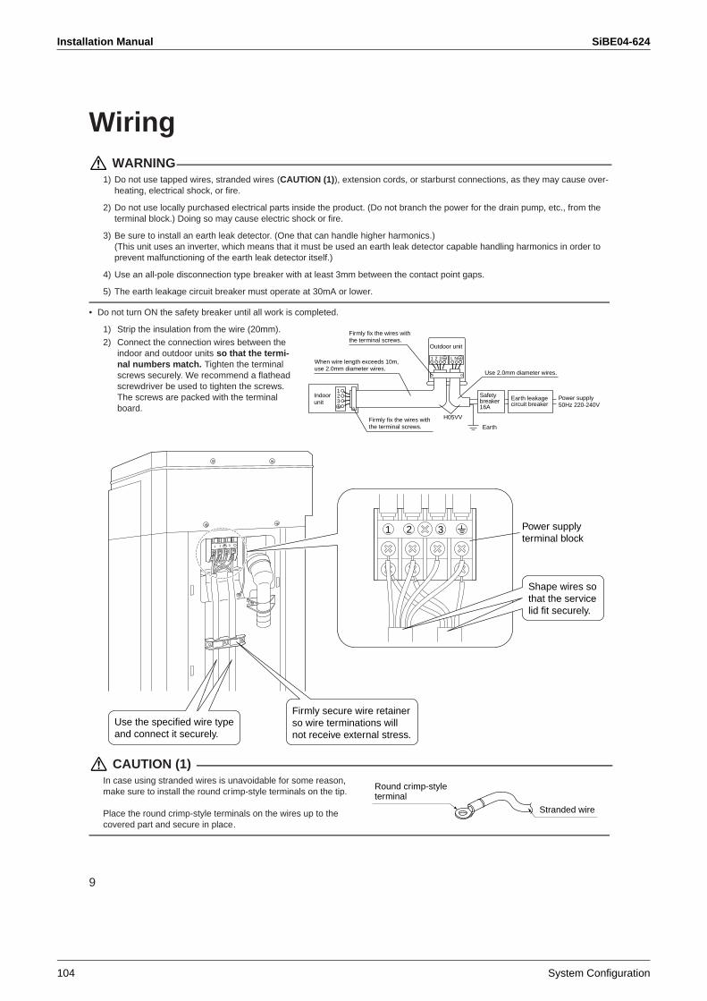
Installation Manual SiBE04-624
104 System Configuration
9
Wiring WARNING
1) Do not use tapped wires, stranded wires (CAUTION (1)), extension cords, or starburst connections, as they may cause over-heating, electrical shock, or fire.
2) Do not use locally purchased electrical parts inside the product. (Do not branch the power for the drain pump, etc., from theterminal block.) Doing so may cause electric shock or fire.
3) Be sure to install an earth leak detector. (One that can handle higher harmonics.)(This unit uses an inverter, which means that it must be used an earth leak detector capable handling harmonics in order to prevent malfunctioning of the earth leak detector itself.)
4) Use an all-pole disconnection type breaker with at least 3mm between the contact point gaps.
5) The earth leakage circuit breaker must operate at 30mA or lower.
• Do not turn ON the safety breaker until all work is completed.
1) Strip the insulation from the wire (20mm).
2) Connect the connection wires between the indoor and outdoor units so that the termi-nal numbers match. Tighten the terminal screws securely. We recommend a flathead screwdriver be used to tighten the screws. The screws are packed with the terminal board.
CAUTION (1)In case using stranded wires is unavoidable for some reason, make sure to install the round crimp-style terminals on the tip.
Place the round crimp-style terminals on the wires up to the covered part and secure in place.
123
1 2 3 L N
Safety breaker 16A
Earth leakage circuit breaker
Earth
When wire length exceeds 10m, use 2.0mm diameter wires.
H05VV
Firmly fix the wires with the terminal screws.
Outdoor unit
Indoorunit
Power supply50Hz 220-240V
Firmly fix the wires with the terminal screws.
Use 2.0mm diameter wires.
1 2 3
1 2 3
Use the specified wire type and connect it securely.
Firmly secure wire retainer so wire terminations will not receive external stress.
Shape wires so that the service lid fit securely.
Power supplyterminal block
Stranded wire
Round crimp-styleterminal
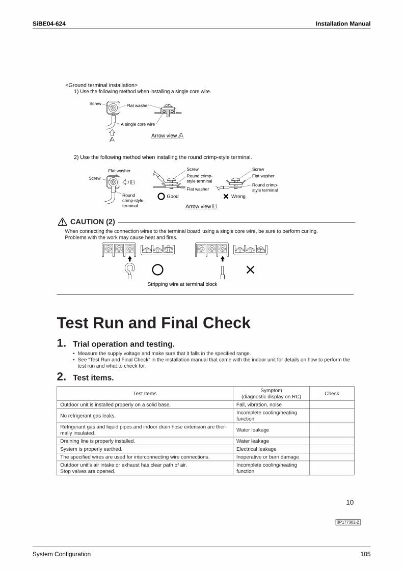
SiBE04-624 Installation Manual
System Configuration 105
10
CAUTION (2)When connecting the connection wires to the terminal board using a single core wire, be sure to perform curling. Problems with the work may cause heat and fires.
Test Run and Final Check1. Trial operation and testing.
• Measure the supply voltage and make sure that it falls in the specified range.• See “Test Run and Final Check” in the installation manual that came with the indoor unit for details on how to perform the
test run and what to check for.
2. Test items.
Test ItemsSymptom
(diagnostic display on RC)Check
Outdoor unit is installed properly on a solid base. Fall, vibration, noise
No refrigerant gas leaks.Incomplete cooling/heating function
Refrigerant gas and liquid pipes and indoor drain hose extension are ther-mally insulated.
Water leakage
Draining line is properly installed. Water leakage
System is properly earthed. Electrical leakage
The specified wires are used for interconnecting wire connections. Inoperative or burn damage
Outdoor unit’s air intake or exhaust has clear path of air.Stop valves are opened.
Incomplete cooling/heating function
2) Use the following method when installing the round crimp-style terminal.
Arrow view
<Ground terminal installation>1) Use the following method when installing a single core wire.
A single core wire
Flat washerScrew
Arrow view
Flat washer
Screw
Roundcrimp-style terminal
Good
Round crimp-style terminal
Flat washer
Screw
Wrong
Flat washer
Round crimp-style terminal
Screw
Stripping wire at terminal block
3P177302-2
System Configuration SiBE04-624
106 System Configuration
2. System ConfigurationAfter the installation and test operation of the room air conditioner have been completed, it should be operated and handled as described below. Every user would like to know the correct method of operation of the room air conditioner, to check if it is capable of cooling (or heating) well, and to know a clever method of using it.In order to meet this expectation of the users, giving sufficient explanations taking enough time can be said to reduce about 80% of the requests for servicing. However good the installation work is and however good the functions are, the customer may blame either the room air conditioner or its installation work because of improper handling. The installation work and handing over of the unit can only be considered to have been completed when its handling has been explained to the user without using technical terms but giving full knowledge of the equipment.
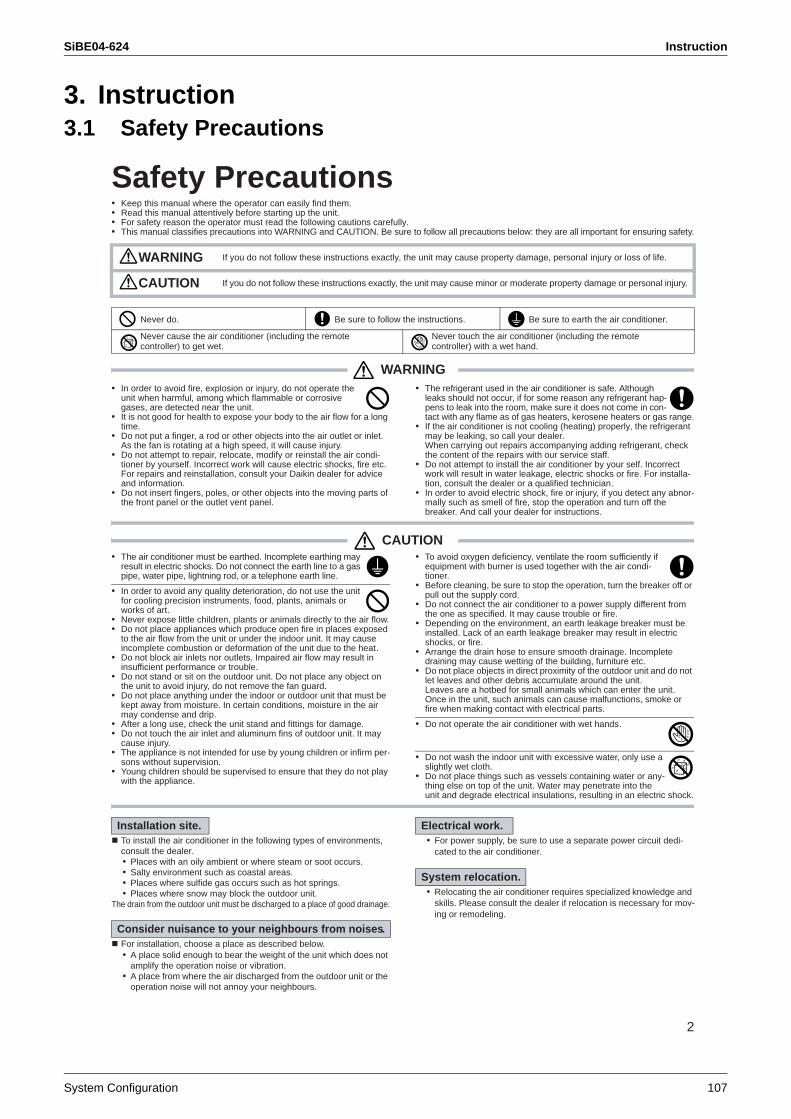
SiBE04-624 Instruction
System Configuration 107
3. Instruction3.1 Safety Precautions
2
Safety Precautions• Keep this manual where the operator can easily find them.• Read this manual attentively before starting up the unit.• For safety reason the operator must read the following cautions carefully.• This manual classifies precautions into WARNING and CAUTION. Be sure to follow all precautions below: they are all important for ensuring safety.
WARNING• In order to avoid fire, explosion or injury, do not operate the
unit when harmful, among which flammable or corrosive gases, are detected near the unit.
• It is not good for health to expose your body to the air flow for a long time.
• Do not put a finger, a rod or other objects into the air outlet or inlet. As the fan is rotating at a high speed, it will cause injury.
• Do not attempt to repair, relocate, modify or reinstall the air condi-tioner by yourself. Incorrect work will cause electric shocks, fire etc. For repairs and reinstallation, consult your Daikin dealer for advice and information.
• Do not insert fingers, poles, or other objects into the moving parts of the front panel or the outlet vent panel.
• The refrigerant used in the air conditioner is safe. Although leaks should not occur, if for some reason any refrigerant hap-pens to leak into the room, make sure it does not come in con-tact with any flame as of gas heaters, kerosene heaters or gas range.
• If the air conditioner is not cooling (heating) properly, the refrigerant may be leaking, so call your dealer.When carrying out repairs accompanying adding refrigerant, check the content of the repairs with our service staff.
• Do not attempt to install the air conditioner by your self. Incorrect work will result in water leakage, electric shocks or fire. For installa-tion, consult the dealer or a qualified technician.
• In order to avoid electric shock, fire or injury, if you detect any abnor-mally such as smell of fire, stop the operation and turn off the breaker. And call your dealer for instructions.
CAUTION• The air conditioner must be earthed. Incomplete earthing may
result in electric shocks. Do not connect the earth line to a gas pipe, water pipe, lightning rod, or a telephone earth line.
• In order to avoid any quality deterioration, do not use the unit for cooling precision instruments, food, plants, animals or works of art.
• Never expose little children, plants or animals directly to the air flow.• Do not place appliances which produce open fire in places exposed
to the air flow from the unit or under the indoor unit. It may cause incomplete combustion or deformation of the unit due to the heat.
• Do not block air inlets nor outlets. Impaired air flow may result in insufficient performance or trouble.
• Do not stand or sit on the outdoor unit. Do not place any object on the unit to avoid injury, do not remove the fan guard.
• Do not place anything under the indoor or outdoor unit that must be kept away from moisture. In certain conditions, moisture in the air may condense and drip.
• After a long use, check the unit stand and fittings for damage.• Do not touch the air inlet and aluminum fins of outdoor unit. It may
cause injury.• The appliance is not intended for use by young children or infirm per-
sons without supervision.• Young children should be supervised to ensure that they do not play
with the appliance.
• To avoid oxygen deficiency, ventilate the room sufficiently if equipment with burner is used together with the air condi-tioner.
• Before cleaning, be sure to stop the operation, turn the breaker off or pull out the supply cord.
• Do not connect the air conditioner to a power supply different from the one as specified. It may cause trouble or fire.
• Depending on the environment, an earth leakage breaker must be installed. Lack of an earth leakage breaker may result in electric shocks, or fire.
• Arrange the drain hose to ensure smooth drainage. Incomplete draining may cause wetting of the building, furniture etc.
• Do not place objects in direct proximity of the outdoor unit and do not let leaves and other debris accumulate around the unit.Leaves are a hotbed for small animals which can enter the unit. Once in the unit, such animals can cause malfunctions, smoke or fire when making contact with electrical parts.
• Do not operate the air conditioner with wet hands.
• Do not wash the indoor unit with excessive water, only use a slightly wet cloth.
• Do not place things such as vessels containing water or any-thing else on top of the unit. Water may penetrate into the unit and degrade electrical insulations, resulting in an electric shock.
To install the air conditioner in the following types of environments, consult the dealer.• Places with an oily ambient or where steam or soot occurs.• Salty environment such as coastal areas.• Places where sulfide gas occurs such as hot springs.• Places where snow may block the outdoor unit.
The drain from the outdoor unit must be discharged to a place of good drainage.
For installation, choose a place as described below.• A place solid enough to bear the weight of the unit which does not
amplify the operation noise or vibration.• A place from where the air discharged from the outdoor unit or the
operation noise will not annoy your neighbours.
• For power supply, be sure to use a separate power circuit dedi-cated to the air conditioner.
• Relocating the air conditioner requires specialized knowledge and skills. Please consult the dealer if relocation is necessary for mov-ing or remodeling.
WARNING If you do not follow these instructions exactly, the unit may cause property damage, personal injury or loss of life.
CAUTION If you do not follow these instructions exactly, the unit may cause minor or moderate property damage or personal injury.
Never do. Be sure to follow the instructions. Be sure to earth the air conditioner.
Never cause the air conditioner (including the remote controller) to get wet.
Never touch the air conditioner (including the remote controller) with a wet hand.
Installation site.
Consider nuisance to your neighbours from noises.
Electrical work.
System relocation.
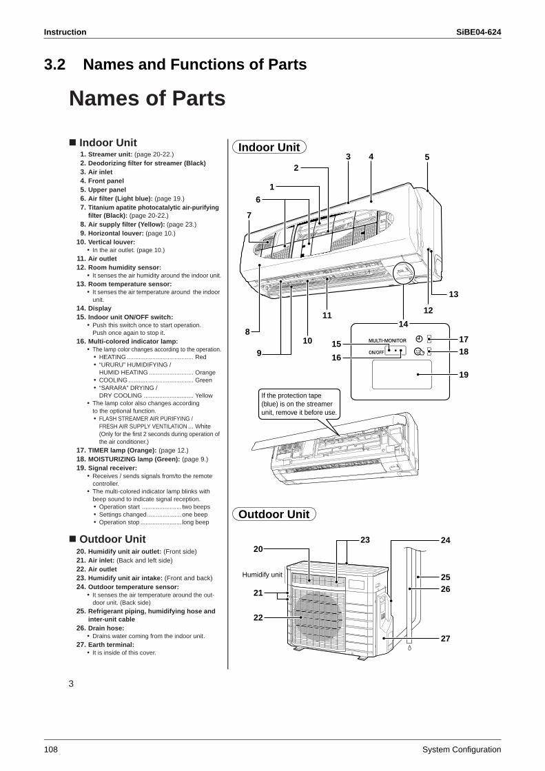
Instruction SiBE04-624
108 System Configuration
3.2 Names and Functions of Parts
3
Names of Parts
Indoor Unit1. Streamer unit: (page 20-22.)2. Deodorizing filter for streamer (Black)3. Air inlet4. Front panel5. Upper panel6. Air filter (Light blue): (page 19.)7. Titanium apatite photocatalytic air-purifying
filter (Black): (page 20-22.)8. Air supply filter (Yellow): (page 23.)9. Horizontal louver: (page 10.)
10. Vertical louver: • In the air outlet. (page 10.)
11. Air outlet12. Room humidity sensor:
• It senses the air humidity around the indoor unit.13. Room temperature sensor:
• It senses the air temperature around the indoor unit.
14. Display15. Indoor unit ON/OFF switch:
• Push this switch once to start operation. Push once again to stop it.
16. Multi-colored indicator lamp:• The lamp color changes according to the operation.
• HEATING....................................... Red• “URURU” HUMIDIFYING /
HUMID HEATING .......................... Orange• COOLING ...................................... Green• “SARARA” DRYING /
DRY COOLING ............................. Yellow• The lamp color also changes according
to the optional function.• FLASH STREAMER AIR PURIFYING /
FRESH AIR SUPPLY VENTILATION ... White(Only for the first 2 seconds during operation of the air conditioner.)
17. TIMER lamp (Orange): (page 12.)18. MOISTURIZING lamp (Green): (page 9.)19. Signal receiver:
• Receives / sends signals from/to the remote controller.
• The multi-colored indicator lamp blinks with beep sound to indicate signal reception.• Operation start ....................... two beeps• Settings changed....................one beep• Operation stop ........................ long beep
Outdoor Unit20. Humidify unit air outlet: (Front side)21. Air inlet: (Back and left side)22. Air outlet23. Humidify unit air intake: (Front and back)24. Outdoor temperature sensor:
• It senses the air temperature around the out-door unit. (Back side)
25. Refrigerant piping, humidifying hose and inter-unit cable
26. Drain hose:• Drains water coming from the indoor unit.
27. Earth terminal:• It is inside of this cover.
Indoor Unit
1
15
16
6
7
10
11
13
12
8
9
23 4 5
1718
19
14
If the protection tape (blue) is on the streamer unit, remove it before use.
Outdoor Unit
20
22
23
21
Humidify unit 25
24
26
27
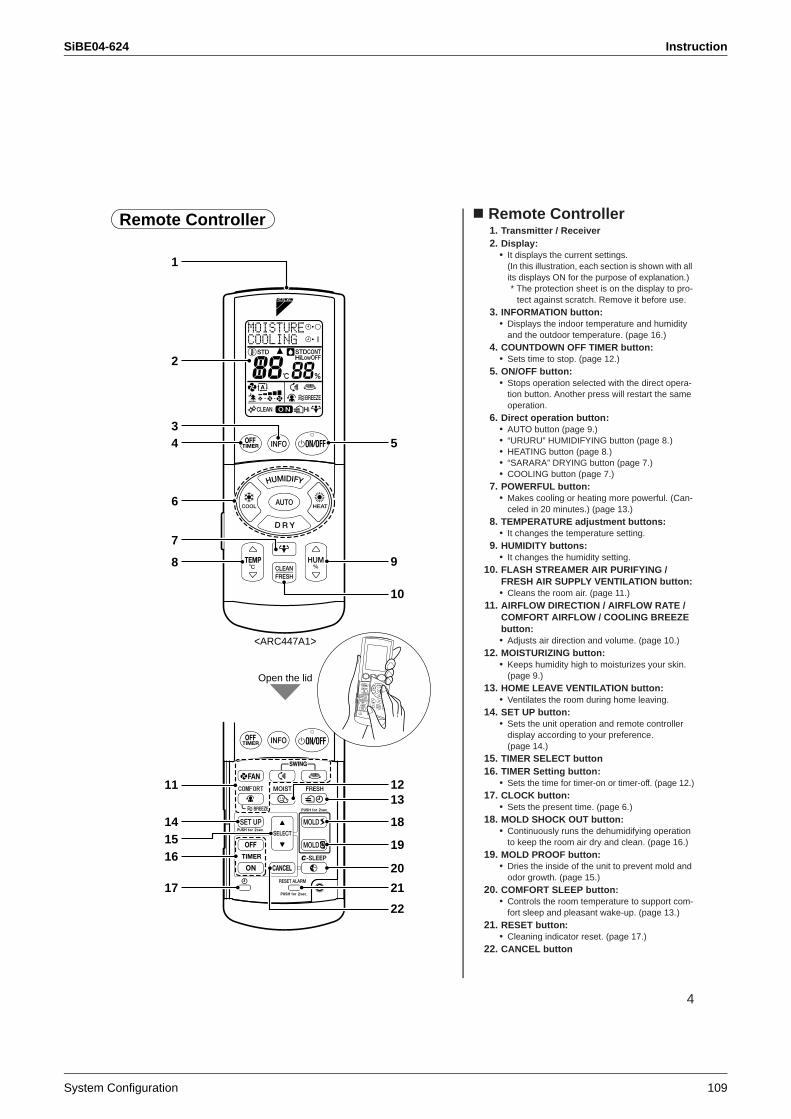
SiBE04-624 Instruction
System Configuration 109
4
Remote Controller1. Transmitter / Receiver2. Display:
• It displays the current settings. (In this illustration, each section is shown with all its displays ON for the purpose of explanation.)* The protection sheet is on the display to pro-
tect against scratch. Remove it before use.3. INFORMATION button:
• Displays the indoor temperature and humidity and the outdoor temperature. (page 16.)
4. COUNTDOWN OFF TIMER button:• Sets time to stop. (page 12.)
5. ON/OFF button:• Stops operation selected with the direct opera-
tion button. Another press will restart the same operation.
6. Direct operation button:• AUTO button (page 9.)• “URURU” HUMIDIFYING button (page 8.)• HEATING button (page 8.)• “SARARA” DRYING button (page 7.)• COOLING button (page 7.)
7. POWERFUL button:• Makes cooling or heating more powerful. (Can-
celed in 20 minutes.) (page 13.)8. TEMPERATURE adjustment buttons:
• It changes the temperature setting.9. HUMIDITY buttons:
• It changes the humidity setting.10. FLASH STREAMER AIR PURIFYING /
FRESH AIR SUPPLY VENTILATION button:• Cleans the room air. (page 11.)
11. AIRFLOW DIRECTION / AIRFLOW RATE / COMFORT AIRFLOW / COOLING BREEZE button:• Adjusts air direction and volume. (page 10.)
12. MOISTURIZING button:• Keeps humidity high to moisturizes your skin.
(page 9.)13. HOME LEAVE VENTILATION button:
• Ventilates the room during home leaving.14. SET UP button:
• Sets the unit operation and remote controller display according to your preference. (page 14.)
15. TIMER SELECT button16. TIMER Setting button:
• Sets the time for timer-on or timer-off. (page 12.)17. CLOCK button:
• Sets the present time. (page 6.)18. MOLD SHOCK OUT button:
• Continuously runs the dehumidifying operation to keep the room air dry and clean. (page 16.)
19. MOLD PROOF button:• Dries the inside of the unit to prevent mold and
odor growth. (page 15.)20. COMFORT SLEEP button:
• Controls the room temperature to support com-fort sleep and pleasant wake-up. (page 13.)
21. RESET button:• Cleaning indicator reset. (page 17.)
22. CANCEL button
Remote Controller
1
3
11
7
Open the lid
<ARC447A1>
2
4
6
8
1415
17
16
5
9
10
1312
22
18
19
20
21
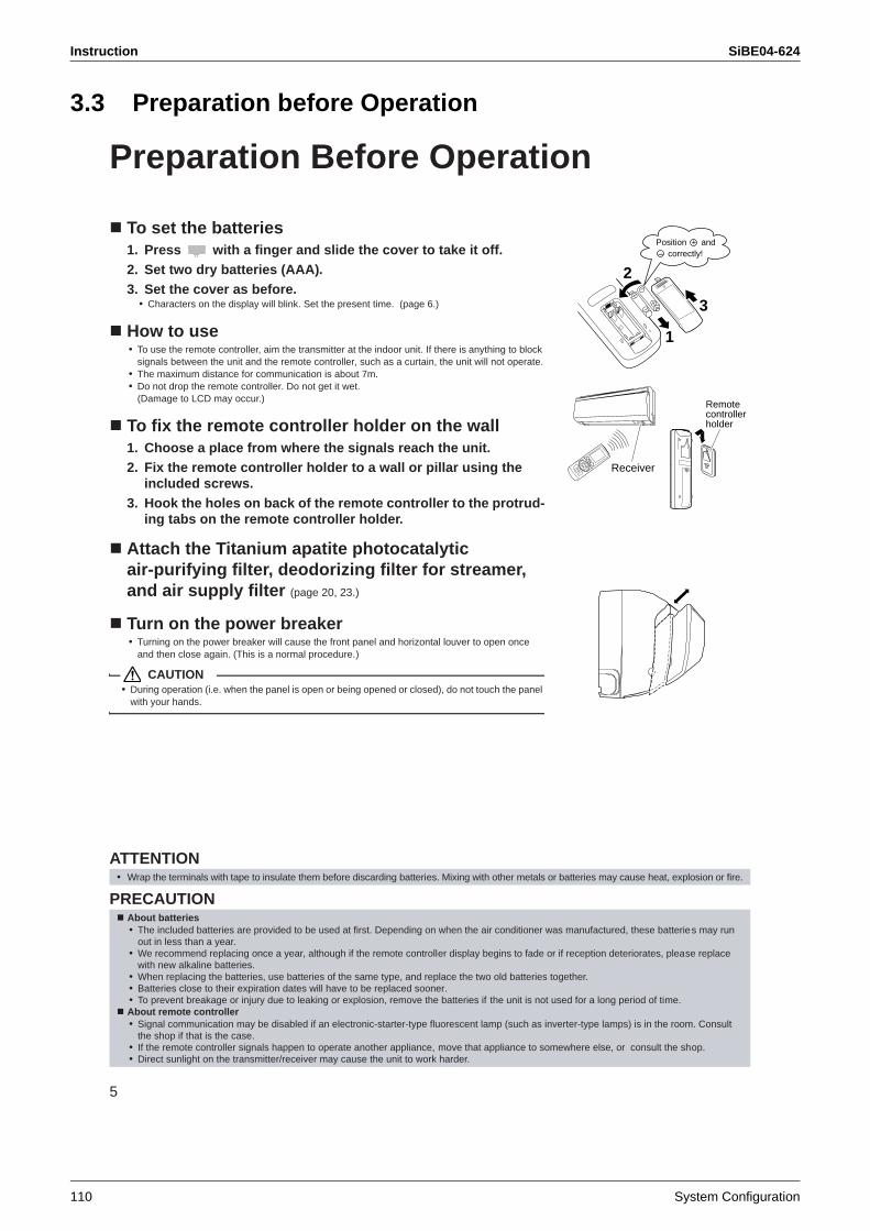
Instruction SiBE04-624
110 System Configuration
3.3 Preparation before Operation
5
Preparation Before Operation
To set the batteries1. Press with a finger and slide the cover to take it off.2. Set two dry batteries (AAA).3. Set the cover as before.
• Characters on the display will blink. Set the present time. (page 6.)
How to use• To use the remote controller, aim the transmitter at the indoor unit. If there is anything to block
signals between the unit and the remote controller, such as a curtain, the unit will not operate.• The maximum distance for communication is about 7m.• Do not drop the remote controller. Do not get it wet.
(Damage to LCD may occur.)
To fix the remote controller holder on the wall1. Choose a place from where the signals reach the unit.2. Fix the remote controller holder to a wall or pillar using the
included screws.3. Hook the holes on back of the remote controller to the protrud-
ing tabs on the remote controller holder.
Attach the Titanium apatite photocatalytic air-purifying filter, deodorizing filter for streamer, and air supply filter (page 20, 23.)
Turn on the power breaker• Turning on the power breaker will cause the front panel and horizontal louver to open once
and then close again. (This is a normal procedure.)
CAUTION• During operation (i.e. when the panel is open or being opened or closed), do not touch the panel
with your hands.
ATTENTION
PRECAUTION
• Wrap the terminals with tape to insulate them before discarding batteries. Mixing with other metals or batteries may cause heat, explosion or fire.
About batteries• The included batteries are provided to be used at first. Depending on when the air conditioner was manufactured, these batteries may run
out in less than a year.• We recommend replacing once a year, although if the remote controller display begins to fade or if reception deteriorates, please replace
with new alkaline batteries.• When replacing the batteries, use batteries of the same type, and replace the two old batteries together.• Batteries close to their expiration dates will have to be replaced sooner.• To prevent breakage or injury due to leaking or explosion, remove the batteries if the unit is not used for a long period of time.About remote controller• Signal communication may be disabled if an electronic-starter-type fluorescent lamp (such as inverter-type lamps) is in the room. Consult
the shop if that is the case.• If the remote controller signals happen to operate another appliance, move that appliance to somewhere else, or consult the shop.• Direct sunlight on the transmitter/receiver may cause the unit to work harder.
2
3
1
Position + and – correctly!
Receiver
Remotecontrollerholder
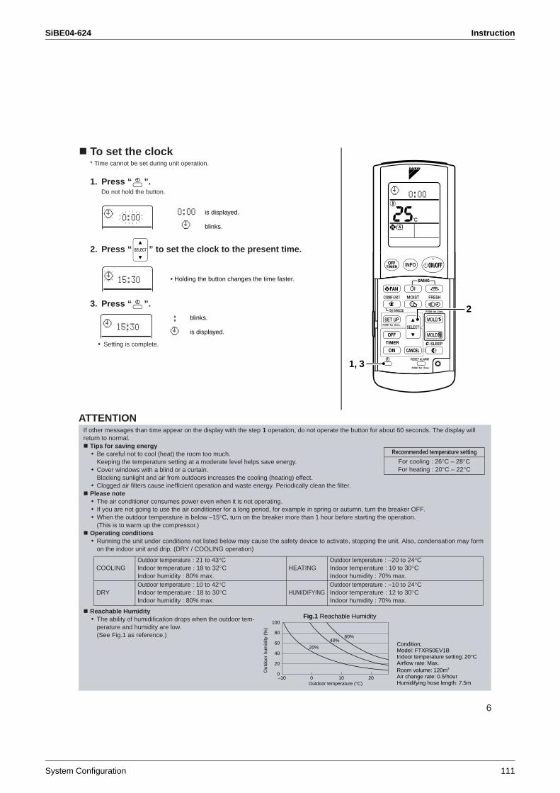
SiBE04-624 Instruction
System Configuration 111
6
To set the clock* Time cannot be set during unit operation.
1. Press “ ”.Do not hold the button.
2. Press “ ” to set the clock to the present time.
3. Press “ ”.
• Setting is complete.
1, 3
2
is displayed.
blinks.
• Holding the button changes the time faster.
blinks.
is displayed.
ATTENTIONIf other messages than time appear on the display with the step 1 operation, do not operate the button for about 60 seconds. The display will return to normal.
Tips for saving energy• Be careful not to cool (heat) the room too much.
Keeping the temperature setting at a moderate level helps save energy.• Cover windows with a blind or a curtain.
Blocking sunlight and air from outdoors increases the cooling (heating) effect.• Clogged air filters cause inefficient operation and waste energy. Periodically clean the filter.Please note• The air conditioner consumes power even when it is not operating.• If you are not going to use the air conditioner for a long period, for example in spring or autumn, turn the breaker OFF.• When the outdoor temperature is below –15°C, turn on the breaker more than 1 hour before starting the operation.
(This is to warm up the compressor.)Operating conditions• Running the unit under conditions not listed below may cause the safety device to activate, stopping the unit. Also, condensation may form
on the indoor unit and drip. (DRY / COOLING operation)
Reachable Humidity • The ability of humidification drops when the outdoor tem-
perature and humidity are low. (See Fig.1 as reference.)
Recommended temperature setting
For cooling : 26°C – 28°CFor heating : 20°C – 22°C
COOLINGOutdoor temperature : 21 to 43°CIndoor temperature : 18 to 32°CIndoor humidity : 80% max.
HEATINGOutdoor temperature : –20 to 24°CIndoor temperature : 10 to 30°CIndoor humidity : 70% max.
DRYOutdoor temperature : 10 to 42°CIndoor temperature : 18 to 30°CIndoor humidity : 80% max.
HUMIDIFYINGOutdoor temperature : –10 to 24°CIndoor temperature : 12 to 30°CIndoor humidity : 70% max.
Condition; Model: FTXR50EV1BIndoor temperature setting: 20°CAirflow rate: Max.Room volume: 120m3
Air change rate: 0.5/hourHumidifying hose length: 7.5m
Fig.1 Reachable Humidity
Outdoor temperature (°C)–100
20
40
60
80
100
0 10 20
20%
40%60%
Out
door
hum
idity
(%
)
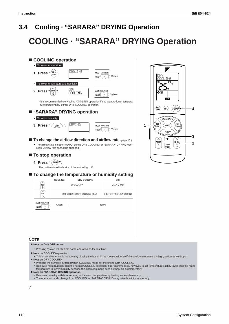
Instruction SiBE04-624
112 System Configuration
3.4 Cooling · “SARARA” DRYING Operation
7
COOLING · “SARARA” DRYING Operation
COOLING operation•
1. Press “ ”.
•
2. Press “ ”.
* It is recommended to switch to COOLING operation if you want to lower tempera-ture preferentially during DRY COOLING operation.
“SARARA” DRYING operation•
3. Press “ ”.
To change the airflow direction and airflow rate (page 10.)
• The airflow rate is set to “AUTO” during DRY COOLING or “SARARA” DRYING oper-ation. Airflow rate cannot be changed.
To stop operation
4. Press “ ”. The multi-colored indicator of the unit will go off.
To change the temperature or humidity setting
1
3
2
4
To lower temperature
Green
To lower temperature and humidity
Yellow
To lower humidity
Yellow
COOLING
Green Yellow
18°C – 32°C –3°C – STD
OFF HIGH STD LOW CONT HIGH STD LOW CONT
DRY COOLING DRY
NOTENote on ON / OFF button
• Pressing “ ” will start the same operation as the last time.
Note on COOLING operation• This air conditioner cools the room by blowing the hot air in the room outside, so if the outside temperature is high, performance drops. Note on DRY COOLING• Pressing the humidity button down in COOLING mode set the unit to DRY COOLING. • Removes more humidity than the normal COOLING operation. It is recommended, however, to set temperature slightly lower than the room
temperature to lower humidity because this operation mode does not heat air supplementary.Note on “SARARA” DRYING operation• Removes humidity with less lowering of the room temperature by heating air supplementary.• The operation mode change from COOLING to “SARARA” DRYING may raise humidity temporarily.
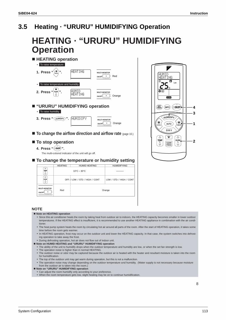
SiBE04-624 Instruction
System Configuration 113
3.5 Heating · “URURU” HUMIDIFYING Operation
8
HEATING · “URURU” HUMIDIFYING Operation
HEATING operation•
1. Press “ ”.
•
2. Press “ ”.
“URURU” HUMIDIFYING operation•
3. Press “ ”.
To change the airflow direction and airflow rate (page 10.)
To stop operation4. Press “ ”.
The multi-colored indicator of the unit will go off.
To change the temperature or humidity setting
3
2
4
1
To raise temperature
Red
To raise temperature and humidity
Orange
To raise humidity
Orange
HEATING
Red Orange
10°C – 30°C ––––––
OFF LOW STD HIGH CONT LOW STD HIGH CONT
HUMID HEATING HUMIDIFYING
NOTENote on HEATING operation• Since this air conditioner heats the room by taking heat from outdoor air to indoors, the HEATING capacity becomes smaller in lower outdoor
temperatures. If the HEATING effect is insufficient, it is recommended to use another HEATING appliance in combination with the air condi-tioner.
• The heat pump system heats the room by circulating hot air around all parts of the room. After the start of HEATING operation, it takes some time before the room gets warmer.
• In HEATING operation, frost may occur on the outdoor unit and lower the HEATING capacity. In that case, the system switches into defrost-ing operation to take away the frost.
• During defrosting operation, hot air does not flow out of indoor unit.Note on HUMID HEATING and “URURU” HUMIDIFYING operation• The ability of the unit to humidify drops when the outdoor temperature and humidity are low, or when the set fan strength is low.• The operation noise is higher than in normal HEATING.• The outdoor noise or odor may be captured because the outdoor air is heated with the heater and resultant moisture is taken into the room
for humidification.• The top of the outdoor unit may get warm during operation, but this is not a malfunction.• The operation noise may change depending on the outdoor temperature and humidity. (Water supply is not necessary because moisture
from the outdoor air is taken into the room.)Note on “URURU” HUMIDIFYING operation• Can adjust the room humidify only according to your preference.• When the room temperature gets low, slight heating may be on to continue humidification.
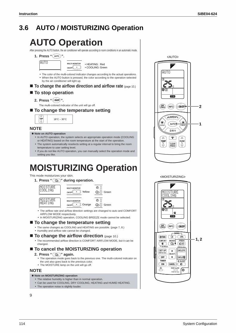
Instruction SiBE04-624
114 System Configuration
3.6 AUTO / MOISTURIZING Operation
9
AUTO OperationAfter pressing the AUTO button, the air conditioner will operate according to room conditions in an automatic mode.
1. Press “ ”.
• The color of the multi-colored indicator changes according to the actual operations.• When the AUTO button is pressed, the color according to the operation selected
by the air conditioner will light up.
To change the airflow direction and airflow rate (page 10.)
To stop operation
2. Press “ ”.The multi-colored indicator of the unit will go off.
To change the temperature setting
NOTE
MOISTURIZING OperationThis mode moisturizes your skin.
1. Press “ ” during operation.
• The airflow rate and airflow direction settings are changed to auto and COMFORT AIRFLOW MODE respectively.
• In MOISTURIZING operation, COOLING BREEZE mode cannot be selected.
To change the temperature setting• The same changes as COOLING and HEATING are possible. (page 7, 8.)• Humidity and airflow rate cannot be changed.
To change the airflow direction (page 10.)• The recommended airflow direction is COMFORT AIRFLOW MODE, but it can be
changed.
To cancel the MOISTURIZING operation2. Press “ ” again.
• The operation mode goes back to the previous one. The multi-colored indicator on the unit also goes back to the previous color.
• The MOISTURE lamp on the unit will go off.
NOTE
Note on AUTO operation• In AUTO operation, the system selects an appropriate operation mode (COOLING
or HEATING) based on the room temperature at the start of the operation.• The system automatically reselects setting at a regular interval to bring the room
temperature to user setting level.• If you do not like AUTO operation, you can manually select the operation mode and
setting you like.
Note on MOISTURIZING operation• The relative humidity is higher than in normal operation.• Can be used for COOLING, DRY COOLING, HEATING and HUMID HEATING.• The operation noise is slightly louder.
• HEATING: Red• COOLING: Green
18°C – 30°C
<MOISTURIZING>
1, 2
1
2
<AUTO>
Yellow Green
Orange Green
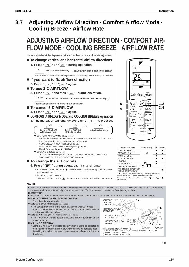
SiBE04-624 Instruction
System Configuration 115
3.7 Adjusting Airflow Direction · Comfort Airflow Mode · Cooling Breeze · Airflow Rate
10
ADJUSTING AIRFLOW DIRECTION · COMFORT AIR-FLOW MODE · COOLING BREEZE · AIRFLOW RATEMore comfortable airflow is provided with airflow direction and airflow rate adjustment .
To change vertical and horizontal airflow directions 1. Press “ ” or “ ” during operation.
The horizontal and vertical louvers respectively move vertically and horizontally automatically.
If you want to fix airflow direction2. Press “ ” or “ ” again.
To use 3-D AIRFLOW3. Press “ ” and then “ ” during operation.
The horizontal and vertical louvers move alternately.
To cancel 3-D AIRFLOW4. Press “ ” or “ ” again.
COMFORT AIRFLOW MODE and COOLING BREEZE operation5. The indication will change every time “ ” is pressed.
COMFORT AIRFLOW MODE operation• The airflow direction and airflow rate are adjusted so that the air from the unit
does not blow directly on the occupants of the room.• < COOLING/DRYING> The flap will go up.• <HEATING/HUMIDIFYING> The flap will go down.• The airflow rate is set to “AUTO”.COOLING BREEZE operation• COOLING BREEZE operation is for COOLING, “SARARA” DRYING and
FLASH STREAMER AIR PURIFYING operation.
To change the airflow rate6. Press “ ” during operation. (Refer to right table.)
• COOLING or HEATING with “ ” or other weak airflow rate may not cool or heat the room sufficiently.
• Indoor unit quiet operationWhen the air flow is set to “ ”, the noise from the indoor unit will become quieter.
6
5
1, 23, 4
• The airflow direction indication will display.(In case of vertical direction)
• The vertical and horizontal airflow direction indications will display.
Displays COMFORTAIRFLOW operation
Displays COOLINGBREEZE operation
Indication disappears
Operating mode
“SARARA” DRYING DRY COOLINGMOISTURIZINGAUTO / COOLINGHEATINGHUMID HEATING“URURU” HUMIDIFYINGFLASH STREAMER AIR PURIFYING / FRESH AIR SUPPLY VENTILATION
Airflow rate setting
••••••
•••
•: COMFORT AIRFLOW MODE operation is possible. : COOLING BREEZE operation is possible.
Five levels of air flow rate setting from “ ” to “ ” plus “ ” “ ” are available.
NOTE• If the unit is operated with the horizontal louvers pointed down and stopped in COOLING, “SARARA” DRYING, or DRY COOLING operation,
the louvers will move automatically after about one hour. (This it to prevent condensation from forming on them.)ATTENTION
• Be sure to use the remote controller to adjust the airflow direction. Manual operation of the louvers may cause it to work improperly.Note on COMFORT AIRFLOW MODE operation• The airflow direction is as fig. 1; Note on COOLING BREEZE operation• The vertical movement of the horizontal louvers with “1/ f breeze”
rhythm provides comfort air like natural breeze. The room temperature is felt cooler with cooling breeze.
Note on Adjusting the vertical airflow direction• The movable area for the horizontal louver is different depending on the
operation mode.Note on 3-D AIRFLOW• Using 3-D AIRFLOW circulates cold air, which tends to be collected at
the bottom of the room, and hot air, which tends to be collected near the ceiling, throughout the room, preventing areas of cold and hot from developing.
A) FLASH STREAMER AIR PURIFYING · FRESH AIR SUPPLY VENTILATION · Individual operation
B) “SARARA” DRYING · COOLINGC) HEATING · “URURU” HUMIDIFYING
A) 15– 70°B) 20– 60°C) 30– 70°
A) 15– 55°B) 45– 55°
C) 25– 55°
STOP
COMFORTAIRFLOWCOOLING 15°
COMFORT AIRFLOWCOOLING 15°
COMFORT AIRFLOWHEATING 75°
COMFORT AIRFLOWHEATING 65°
Fig.1
Fig.2
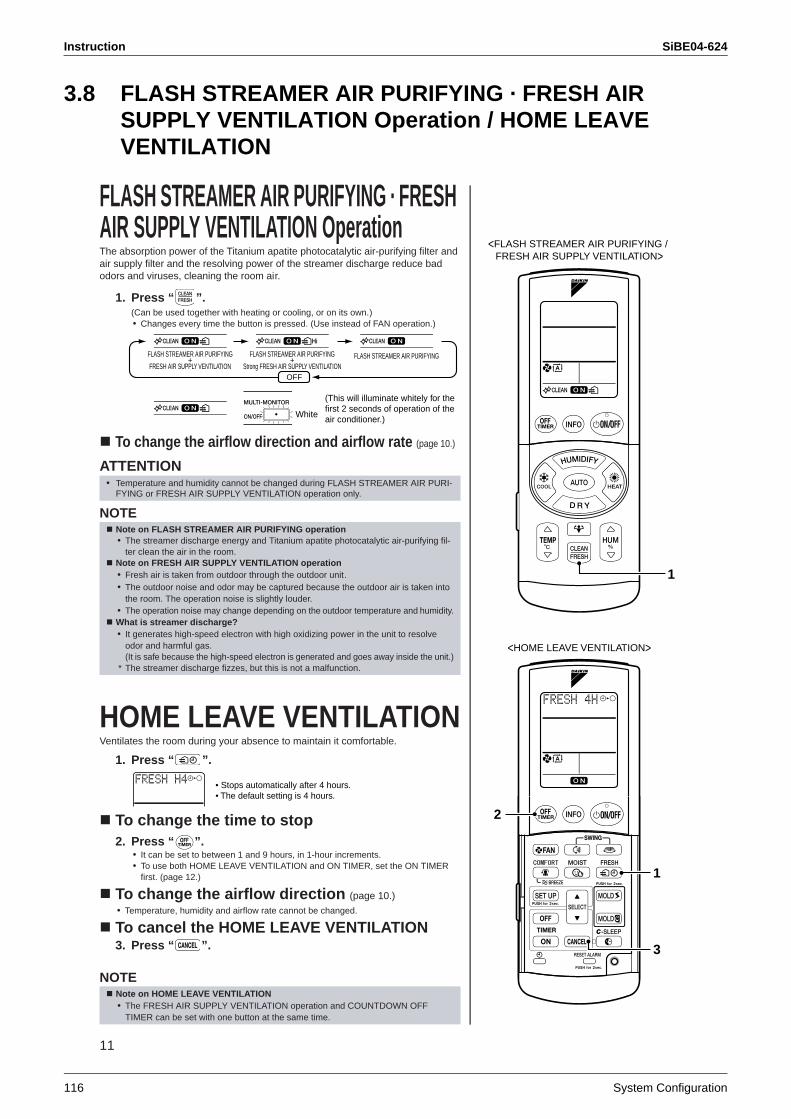
Instruction SiBE04-624
116 System Configuration
3.8 FLASH STREAMER AIR PURIFYING · FRESH AIR SUPPLY VENTILATION Operation / HOME LEAVE VENTILATION
11
FLASH STREAMER AIR PURIFYING · FRESH AIR SUPPLY VENTILATION OperationThe absorption power of the Titanium apatite photocatalytic air-purifying filter and air supply filter and the resolving power of the streamer discharge reduce bad odors and viruses, cleaning the room air.
1. Press “ ”.(Can be used together with heating or cooling, or on its own.)• Changes every time the button is pressed. (Use instead of FAN operation.)
To change the airflow direction and airflow rate (page 10.)
ATTENTION
NOTE
HOME LEAVE VENTILATIONVentilates the room during your absence to maintain it comfortable.
1. Press “ ”.
To change the time to stop2. Press “ ”.
• It can be set to between 1 and 9 hours, in 1-hour increments.• To use both HOME LEAVE VENTILATION and ON TIMER, set the ON TIMER
first. (page 12.)
To change the airflow direction (page 10.)• Temperature, humidity and airflow rate cannot be changed.
To cancel the HOME LEAVE VENTILATION3. Press “ ”.
NOTE
• Temperature and humidity cannot be changed during FLASH STREAMER AIR PURI-FYING or FRESH AIR SUPPLY VENTILATION operation only.
Note on FLASH STREAMER AIR PURIFYING operation• The streamer discharge energy and Titanium apatite photocatalytic air-purifying fil-
ter clean the air in the room.Note on FRESH AIR SUPPLY VENTILATION operation• Fresh air is taken from outdoor through the outdoor unit.• The outdoor noise and odor may be captured because the outdoor air is taken into
the room. The operation noise is slightly louder. • The operation noise may change depending on the outdoor temperature and humidity.What is streamer discharge?• It generates high-speed electron with high oxidizing power in the unit to resolve
odor and harmful gas. (It is safe because the high-speed electron is generated and goes away inside the unit.)
* The streamer discharge fizzes, but this is not a malfunction.
Note on HOME LEAVE VENTILATION• The FRESH AIR SUPPLY VENTILATION operation and COUNTDOWN OFF
TIMER can be set with one button at the same time.
1
<FLASH STREAMER AIR PURIFYING / FRESH AIR SUPPLY VENTILATION>
3
1
2
<HOME LEAVE VENTILATION>
FLASH STREAMER AIR PURIFYING+
FRESH AIR SUPPLY VENTILATION
FLASH STREAMER AIR PURIFYING+
Strong FRESH AIR SUPPLY VENTILATIONFLASH STREAMER AIR PURIFYING
OFF
White
(This will illuminate whitely for the first 2 seconds of operation of the air conditioner.)
• Stops automatically after 4 hours.• The default setting is 4 hours.
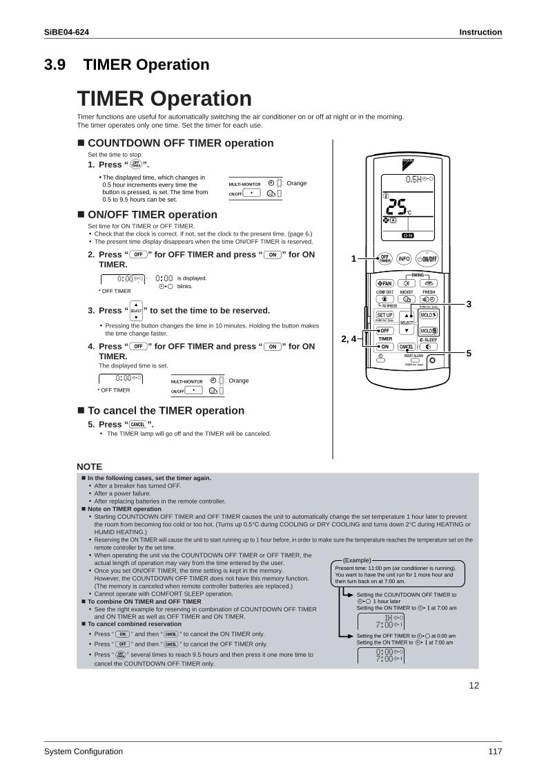
SiBE04-624 Instruction
System Configuration 117
3.9 TIMER Operation
12
TIMER OperationTimer functions are useful for automatically switching the air conditioner on or off at night or in the morning. The timer operates only one time. Set the timer for each use.
COUNTDOWN OFF TIMER operationSet the time to stop.
1. Press “ ”.
ON/OFF TIMER operationSet time for ON TIMER or OFF TIMER.• Check that the clock is correct. If not, set the clock to the present time. (page 6.)• The present time display disappears when the time ON/OFF TIMER is reserved.
2. Press “ ” for OFF TIMER and press “ ” for ON TIMER.
3. Press “ ” to set the time to be reserved.
• Pressing the button changes the time in 10 minutes. Holding the button makes the time change faster.
4. Press “ ” for OFF TIMER and press “ ” for ON TIMER.The displayed time is set.
To cancel the TIMER operation5. Press “ ”.
• The TIMER lamp will go off and the TIMER will be canceled.
1
2, 4
3
5
• The displayed time, which changes in 0.5 hour increments every time the button is pressed, is set. The time from 0.5 to 9.5 hours can be set.
Orange
* OFF TIMER
is displayed.
blinks.
* OFF TIMER
Orange
NOTEIn the following cases, set the timer again.• After a breaker has turned OFF.• After a power failure.• After replacing batteries in the remote controller.Note on TIMER operation• Starting COUNTDOWN OFF TIMER and OFF TIMER causes the unit to automatically change the set temperature 1 hour later to prevent
the room from becoming too cold or too hot. (Turns up 0.5°C during COOLING or DRY COOLING and turns down 2°C during HEATING or HUMID HEATING.)
• Reserving the ON TIMER will cause the unit to start running up to 1 hour before, in order to make sure the temperature reaches the temperature set on the remote controller by the set time.
• When operating the unit via the COUNTDOWN OFF TIMER or OFF TIMER, the actual length of operation may vary from the time entered by the user.
• Once you set ON/OFF TIMER, the time setting is kept in the memory. However, the COUNTDOWN OFF TIMER does not have this memory function. (The memory is canceled when remote controller batteries are replaced.)
• Cannot operate with COMFORT SLEEP operation.To combine ON TIMER and OFF TIMER• See the right example for reserving in combination of COUNTDOWN OFF TIMER
and ON TIMER as well as OFF TIMER and ON TIMER.To cancel combined reservation
• Press “ ” and then “ ” to cancel the ON TIMER only.
• Press “ ” and then “ ” to cancel the OFF TIMER only.
• Press “ ” several times to reach 9.5 hours and then press it one more time to
cancel the COUNTDOWN OFF TIMER only.
(Example)Present time: 11:00 pm (air conditioner is running). You want to have the unit run for 1 more hour and then turn back on at 7:00 am.
Setting the COUNTDOWN OFF TIMER to 1 hour laterSetting the ON TIMER to at 7:00 am
Setting the OFF TIMER to at 0:00 amSetting the ON TIMER to at 7:00 am
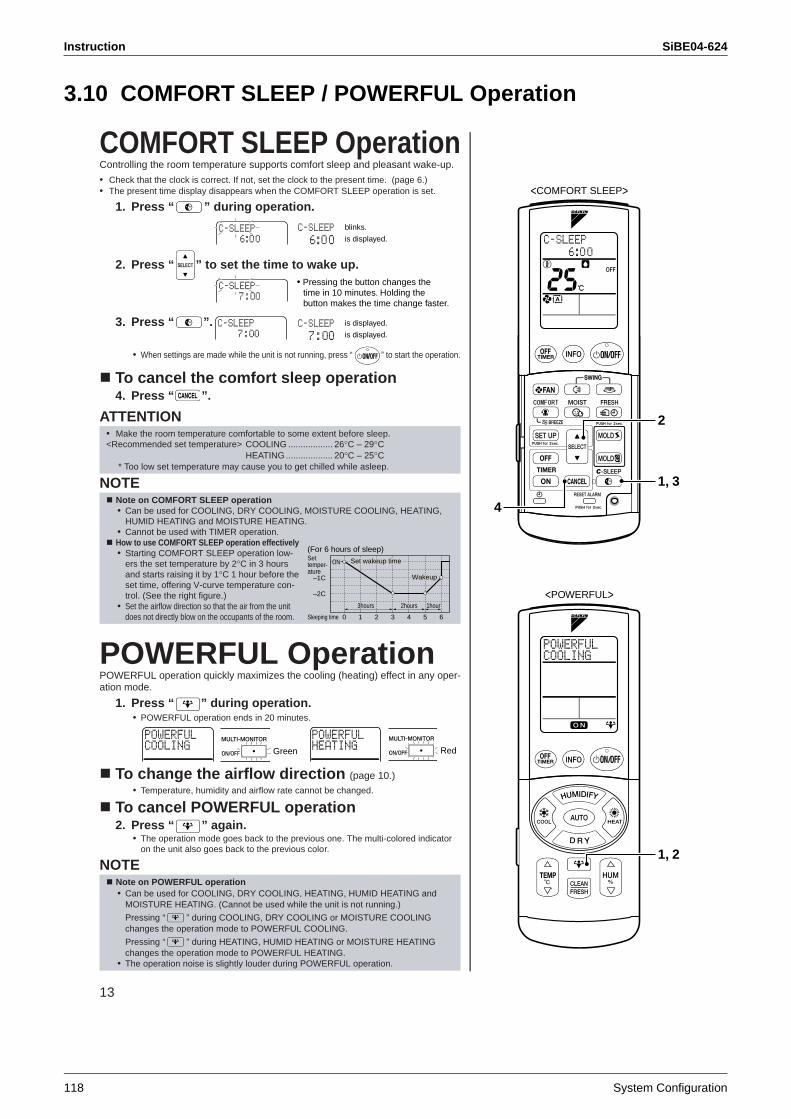
Instruction SiBE04-624
118 System Configuration
3.10 COMFORT SLEEP / POWERFUL Operation
13
COMFORT SLEEP OperationControlling the room temperature supports comfort sleep and pleasant wake-up.
• Check that the clock is correct. If not, set the clock to the present time. (page 6.)• The present time display disappears when the COMFORT SLEEP operation is set.
1. Press “ ” during operation.
2. Press “ ” to set the time to wake up.
3. Press “ ”.
• When settings are made while the unit is not running, press “ ” to start the operation.
To cancel the comfort sleep operation4. Press “ ”.
ATTENTION
NOTE
POWERFUL OperationPOWERFUL operation quickly maximizes the cooling (heating) effect in any oper-ation mode.
1. Press “ ” during operation.• POWERFUL operation ends in 20 minutes.
To change the airflow direction (page 10.)• Temperature, humidity and airflow rate cannot be changed.
To cancel POWERFUL operation2. Press “ ” again.
• The operation mode goes back to the previous one. The multi-colored indicator on the unit also goes back to the previous color.
NOTE
• Make the room temperature comfortable to some extent before sleep.<Recommended set temperature> COOLING .................. 26°C – 29°C
HEATING................... 20°C – 25°C * Too low set temperature may cause you to get chilled while asleep.
Note on COMFORT SLEEP operation• Can be used for COOLING, DRY COOLING, MOISTURE COOLING, HEATING,
HUMID HEATING and MOISTURE HEATING.• Cannot be used with TIMER operation.How to use COMFORT SLEEP operation effectively• Starting COMFORT SLEEP operation low-
ers the set temperature by 2°C in 3 hours and starts raising it by 1°C 1 hour before the set time, offering V-curve temperature con-trol. (See the right figure.)
• Set the airflow direction so that the air from the unit does not directly blow on the occupants of the room.
Note on POWERFUL operation• Can be used for COOLING, DRY COOLING, HEATING, HUMID HEATING and
MOISTURE HEATING. (Cannot be used while the unit is not running.)
Pressing “ ” during COOLING, DRY COOLING or MOISTURE COOLING changes the operation mode to POWERFUL COOLING.
Pressing “ ” during HEATING, HUMID HEATING or MOISTURE HEATING changes the operation mode to POWERFUL HEATING.
• The operation noise is slightly louder during POWERFUL operation.
<COMFORT SLEEP>
1, 3
2
4
1, 2
<POWERFUL>
blinks.
is displayed.
• Pressing the button changes the time in 10 minutes. Holding the button makes the time change faster.
is displayed.
is displayed.
0Sleeping time
(For 6 hours of sleep)Settemper-ature
2hours2hours2hours
1
ONON
2 3 4 5 6
–1C
ON
–2C
Set wakeup timeSet wakeup time
WakeupWakeup
Set wakeup time
Wakeup
1hour1hour1hour3hours3hours3hours
Green Red
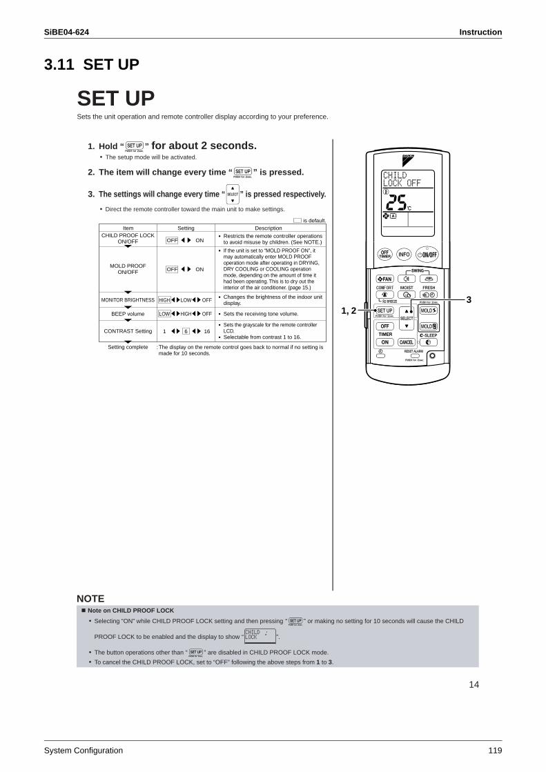
SiBE04-624 Instruction
System Configuration 119
3.11 SET UP
14
SET UPSets the unit operation and remote controller display according to your preference.
1. Hold “ ” for about 2 seconds.• The setup mode will be activated.
2. The item will change every time “ ” is pressed.
3. The settings will change every time “ ” is pressed respectively.
• Direct the remote controller toward the main unit to make settings.
1, 23
Item Setting Descriptionis default.
CHILD PROOF LOCKON/OFF
MOLD PROOFON/OFF
MONITOR BRIGHTNESS
BEEP volume
CONTRAST Setting
Setting complete :The display on the remote control goes back to normal if no setting is made for 10 seconds.
• Restricts the remote controller operations to avoid misuse by children. (See NOTE.)
• If the unit is set to “MOLD PROOF ON”, it may automatically enter MOLD PROOF operation mode after operating in DRYING, DRY COOLING or COOLING operation mode, depending on the amount of time it had been operating. This is to dry out the interior of the air conditioner. (page 15.)
• Changes the brightness of the indoor unit display.
• Sets the receiving tone volume.
• Sets the grayscale for the remote controller LCD.
• Selectable from contrast 1 to 16.
OFF ON
OFF ON
HIGH LOW OFF
LOW HIGH OFF
1 6 16
NOTENote on CHILD PROOF LOCK
• Selecting “ON” while CHILD PROOF LOCK setting and then pressing “ ” or making no setting for 10 seconds will cause the CHILD
PROOF LOCK to be enabled and the display to show “ ”.
• The button operations other than “ ” are disabled in CHILD PROOF LOCK mode.
• To cancel the CHILD PROOF LOCK, set to “OFF” following the above steps from 1 to 3.
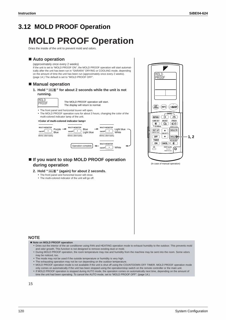
Instruction SiBE04-624
120 System Configuration
3.12 MOLD PROOF Operation
15
MOLD PROOF OperationDries the inside of the unit to prevent mold and odors.
Auto operation (approximately once every 2 weeks)If the unit is set to “MOLD PROOF ON”, the MOLD PROOF operation will start automat-ically after the unit has been run in “SARARA” DRYING or COOLING mode, depending on the amount of time the unit has been run (approximately once every 2 weeks). (page 14.) The default is set to “MOLD PROOF OFF”.
Manual operation1. Hold “ ” for about 2 seconds while the unit is not
running.
• The front panel and horizontal louver will open.• The MOLD PROOF operation runs for about 3 hours, changing the color of the
multi-colored indicator lamp of the unit.
If you want to stop MOLD PROOF operation during operation2. Hold “ ” (again) for about 2 seconds.
• The front panel and horizontal louver will close.• The multi-colored indicator of the unit will go off.
(In case of manual operation)
1, 2
The MOLD PROOF operation will start.The display will return to normal.
<Color of multi-colored indicator lamp>
Blinks alternately.
Operation complete
PurpleBlue
Blinks alternately.
BlueLight blue
Blinks alternately.
Light blueWhite
White
NOTENote on MOLD PROOF operation• Dries out the interior of the air conditioner using FAN and HEATING operation mode to exhaust humidity to the outdoor. This prevents mold
and odor growth. This function is not designed to remove existing dust or mold.• During MOLD PROOF operation, the room temperature may rise and humidity from the machine may be sent into the room. Some odors
may be noticed, too. • The mode may not be used if the outside temperature or humidity is very high.• The exhausting operation may not be run depending on the outdoor temperature.• MOLD PROOF operation mode is not available if the unit is shut off using the COUNTDOWN OFF TIMER. MOLD PROOF operation mode
only comes on automatically if the unit has been stopped using the operation/stop switch on the remote controller or the main unit.• If MOLD PROOF operation is stopped during AUTO mode, the operation comes on automatically next time, depending on the amount of
time the unit had been operating. To cancel the AUTO mode, set to “MOLD PROOF OFF”. (page 14.)
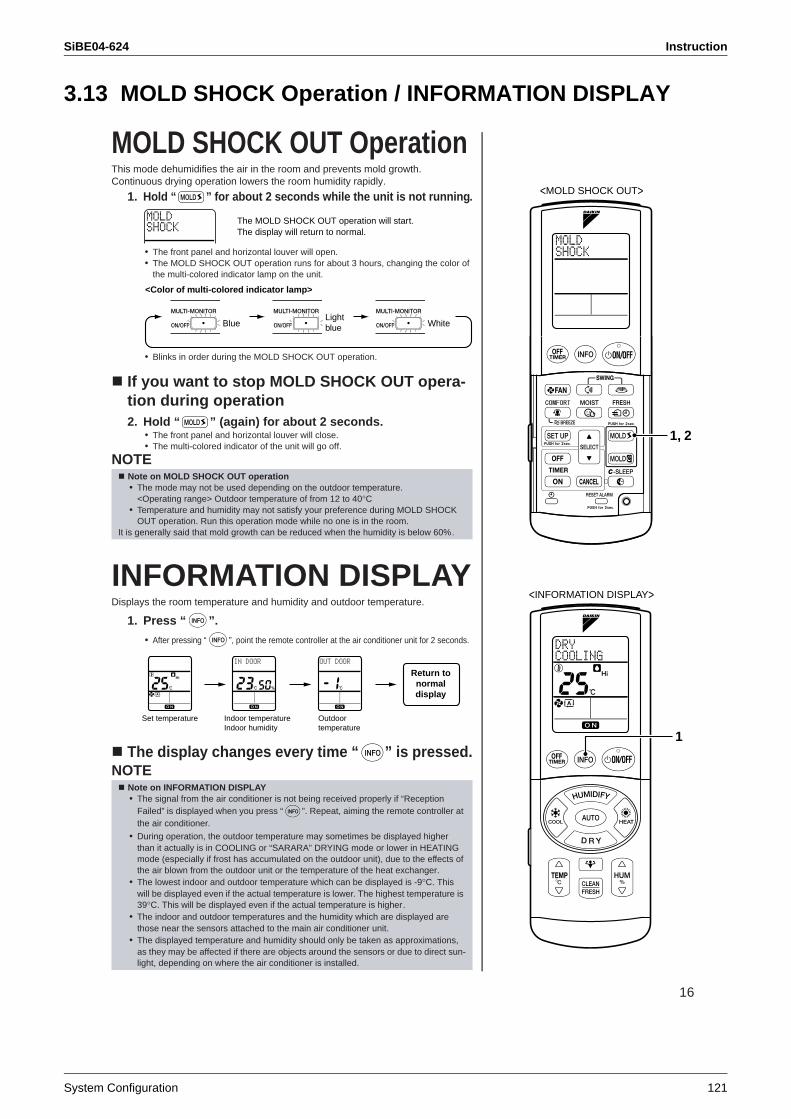
SiBE04-624 Instruction
System Configuration 121
3.13 MOLD SHOCK Operation / INFORMATION DISPLAY
16
MOLD SHOCK OUT OperationThis mode dehumidifies the air in the room and prevents mold growth.Continuous drying operation lowers the room humidity rapidly.
1. Hold “ ” for about 2 seconds while the unit is not running.
• The front panel and horizontal louver will open.• The MOLD SHOCK OUT operation runs for about 3 hours, changing the color of
the multi-colored indicator lamp on the unit.
• Blinks in order during the MOLD SHOCK OUT operation.
If you want to stop MOLD SHOCK OUT opera-tion during operation2. Hold “ ” (again) for about 2 seconds.
• The front panel and horizontal louver will close.• The multi-colored indicator of the unit will go off.
NOTE
INFORMATION DISPLAYDisplays the room temperature and humidity and outdoor temperature.
1. Press “ ”.
• After pressing “ ”, point the remote controller at the air conditioner unit for 2 seconds.
The display changes every time “ ” is pressed.NOTE
Note on MOLD SHOCK OUT operation• The mode may not be used depending on the outdoor temperature.
<Operating range> Outdoor temperature of from 12 to 40°C• Temperature and humidity may not satisfy your preference during MOLD SHOCK
OUT operation. Run this operation mode while no one is in the room.It is generally said that mold growth can be reduced when the humidity is below 60%.
Note on INFORMATION DISPLAY• The signal from the air conditioner is not being received properly if “Reception
Failed” is displayed when you press “ ”. Repeat, aiming the remote controller at the air conditioner.
• During operation, the outdoor temperature may sometimes be displayed higher than it actually is in COOLING or “SARARA” DRYING mode or lower in HEATING mode (especially if frost has accumulated on the outdoor unit), due to the effects of the air blown from the outdoor unit or the temperature of the heat exchanger.
• The lowest indoor and outdoor temperature which can be displayed is -9°C. This will be displayed even if the actual temperature is lower. The highest temperature is 39°C. This will be displayed even if the actual temperature is higher.
• The indoor and outdoor temperatures and the humidity which are displayed are those near the sensors attached to the main air conditioner unit.
• The displayed temperature and humidity should only be taken as approximations, as they may be affected if there are objects around the sensors or due to direct sun-light, depending on where the air conditioner is installed.
1, 2
<MOLD SHOCK OUT>
1
<INFORMATION DISPLAY>
The MOLD SHOCK OUT operation will start.The display will return to normal.
<Color of multi-colored indicator lamp>
Blue WhiteLightblue
Return tonormaldisplay
Set temperature Indoor temperatureIndoor humidity
Outdoortemperature
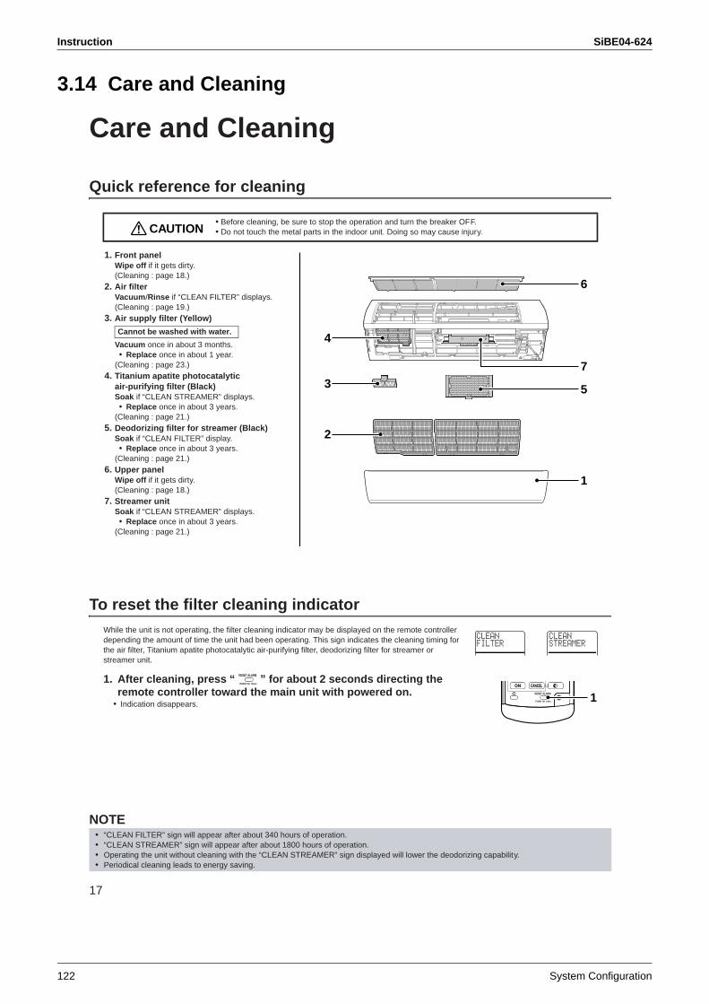
Instruction SiBE04-624
122 System Configuration
3.14 Care and Cleaning
17
Care and Cleaning
Quick reference for cleaning
1. Front panelWipe off if it gets dirty.(Cleaning : page 18.)
2. Air filterVacuum/Rinse if “CLEAN FILTER” displays.(Cleaning : page 19.)
3. Air supply filter (Yellow)
Vacuum once in about 3 months.• Replace once in about 1 year.
(Cleaning : page 23.)4. Titanium apatite photocatalytic
air-purifying filter (Black)Soak if “CLEAN STREAMER” displays.• Replace once in about 3 years.
(Cleaning : page 21.)5. Deodorizing filter for streamer (Black)
Soak if “CLEAN FILTER” display.• Replace once in about 3 years.
(Cleaning : page 21.)6. Upper panel
Wipe off if it gets dirty.(Cleaning : page 18.)
7. Streamer unitSoak if “CLEAN STREAMER” displays.• Replace once in about 3 years.
(Cleaning : page 21.)
To reset the filter cleaning indicatorWhile the unit is not operating, the filter cleaning indicator may be displayed on the remote controller depending the amount of time the unit had been operating. This sign indicates the cleaning timing for the air filter, Titanium apatite photocatalytic air-purifying filter, deodorizing filter for streamer or streamer unit.
1. After cleaning, press “ ” for about 2 seconds directing the remote controller toward the main unit with powered on.
• Indication disappears.
NOTE
• Before cleaning, be sure to stop the operation and turn the breaker OFF.• Do not touch the metal parts in the indoor unit. Doing so may cause injury.
Cannot be washed with water.
• “CLEAN FILTER” sign will appear after about 340 hours of operation.• “CLEAN STREAMER” sign will appear after about 1800 hours of operation.• Operating the unit without cleaning with the “CLEAN STREAMER” sign displayed will lower the deodorizing capability.• Periodical cleaning leads to energy saving.
CAUTION
1
6
2
3
4
5
7
1
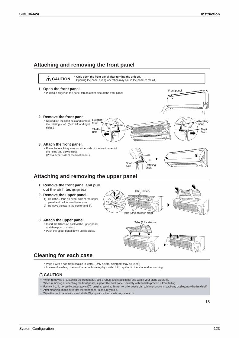
SiBE04-624 Instruction
System Configuration 123
18
Attaching and removing the front panel
1. Open the front panel.• Placing a finger on the panel tab on either side of the front panel.
2. Remove the front panel.• Spread out the shaft hole and remove
the rotating shaft. (Both left and right sides.)
3. Attach the front panel. • Place the revolving axes on either side of the front panel into
the holes and slowly close. (Press either side of the front panel.)
Attaching and removing the upper panel
1. Remove the front panel and pull out the air filter. (page 19.)
2. Remove the upper panel.1) Hold the 2 tabs on either side of the upper
panel and pull forward to remove. 2) Remove the tab in the center and lift.
3. Attach the upper panel.• Insert the 3 tabs on back of the upper panel
and then push it down.• Push the upper panel down until it clicks.
Cleaning for each case• Wipe it with a soft cloth soaked in water. (Only neutral detergent may be used.)• In case of washing the front panel with water, dry it with cloth, dry it up in the shade after washing.
CAUTION
• Only open the front panel after turning the unit off. Opening the panel during operation may cause the panel to fall off.
• When removing or attaching the front panel, use a robust and stable stool and watch your steps carefully. • When removing or attaching the front panel, support the front panel securely with hand to prevent it from falling.• For cleaning, do not use hot water above 40˚C, benz ine, gasoline, thinner, nor other volatile oils, polishing compound, scrubbing brushes, nor other hand stuff.• After cleaning, make sure that the front panel is securely fixed.• Wipe the front panel with a soft cloth. Wiping with a hard cloth may scratch it.
CAUTION
Front panel
Rotatingshaft Rotating
shaft
Shafthole
Shafthole
Shafthole Rotating
shaft
Tabs (One on each side)
Tab (Center)
Tabs (3 locations)
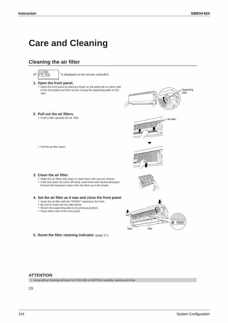
Instruction SiBE04-624
124 System Configuration
19
Care and Cleaning
Cleaning the air filter
(If “ ” is displayed on the remote controller)
1. Open the front panel. • Open the front panel by placing a finger on the panel tab on either side
of the front panel and then secure it using the supporting plate on the right.
2. Pull out the air filters.• Push a little upwards the air filter.
• Pull the air filter down.
3. Clean the air filter.• Wash the air filters with water or clean them with vacuum cleaner.• If the dust does not come off easily, wash them with neutral detergent
thinned with lukewarm water, then dry them up in the shade.
4. Set the air filter as it was and close the front panel.• Insert the air filter with the “FRONT” marking to the front.• Be sure to insert the two tabs below.• Return the supporting plate to its previous position.• Press either side of the front panel.
5. Reset the filter cleaning indicator. (page 17.)
ATTENTION• Using without cleaning will lower the COOLING or HEATING capability, wasting electricity.
Supporting plate
Air filter
TabsTabs
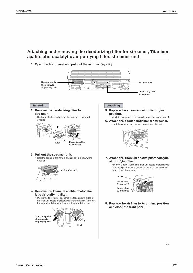
SiBE04-624 Instruction
System Configuration 125
20
Attaching and removing the deodorizing filter for streamer, Titanium apatite photocatalytic air-purifying filter, streamer unit
1. Open the front panel and pull out the air filter. (page 19.)
2. Remove the deodorizing filter for streamer.• Discharge the tab and pull out the knob in a downward
direction.
3. Pull out the streamer unit.• Hold the center of the handle and pull out in a downward
direction.
4. Remove the Titanium apatite photocata-lytic air-purifying filter.• Pull up the filter frame, discharge the tabs on both sides of
the Titanium apatite photocatalytic air-purifying filter from the hooks, and pull down the filter in a downward direction.
5. Replace the streamer unit to its original position.• Attach the streamer unit in opposite procedure to removing 3.
6. Attach the deodorizing filter for streamer.• Insert the deodorizing filter for streamer until it clicks.
7. Attach the Titanium apatite photocatalytic air-purifying filter.• Insert the 2 upper tabs on the Titanium apatite photocatalytic
air-purifying filter into the guides on the main unit and then hook up the 2 lower tabs.
8. Replace the air filter to its original position and close the front panel.
Titanium apatite photocatalyticair-purifying filter
Streamer unit
Deodorizing filter for streamer
Removing
TabKnob Deodorizing filter
for streamer
Streamer unit
Titanium apatite photocatalyticair-purifying filter Tab
Hook
Attaching
Guide
Upper tabs(2 locations)
Lower tabs(2 locations)
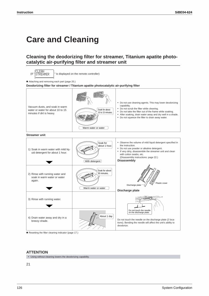
Instruction SiBE04-624
126 System Configuration
21
Care and Cleaning
Cleaning the deodorizing filter for streamer, Titanium apatite photo-catalytic air-purifying filter and streamer unit
(If “ ” is displayed on the remote controller)
Attaching and removing each part (page 20.)
Deodorizing filter for streamer / Titanium apatite photocatalytic air-purifying filter
Streamer unit
Resetting the filter cleaning indicator (page 17.)
ATTENTION
Vacuum dusts, and soak in warm water or water for about 10 to 15 minutes if dirt is heavy.
• Do not use cleaning agents. This may lower deodorizing capability.
• Do not scrub the filter while cleaning.• Do not take the filter out of the frame while soaking.• After soaking, drain water away and dry well in a shade.• Do not squeeze the filter to drain away water.
1) Soak in warm water with mild liq-uid detergent for about 1 hour.
• Observe the volume of mild liquid detergent specified in the instruction.
• Do not use powder or alkaline detergent.• If very dirty, disassemble the streamer unit and clean
with cotton swabs, etc. (Disassembly instructions: page 22.)
Disassembly
Discharge plate
Do not touch the needle on the discharge plate (2 loca-tions). Bending the needle will affect the unit’s ability to deodorize.
2) Rinse with running water and soak in warm water or water again.
3) Rinse with running water.
4) Drain water away and dry in a breezy shade.
• Using without cleaning lowers the deodorizing capability.
Warm water or water
Soak for about 10 to 15 minutes.
Soak for about 1 hour.
With detergent
Discharge platePlastic cover
Do not touch the needle on the discharge plate.
Soak for about 30 minutes.
Warm water or water
About 1 day
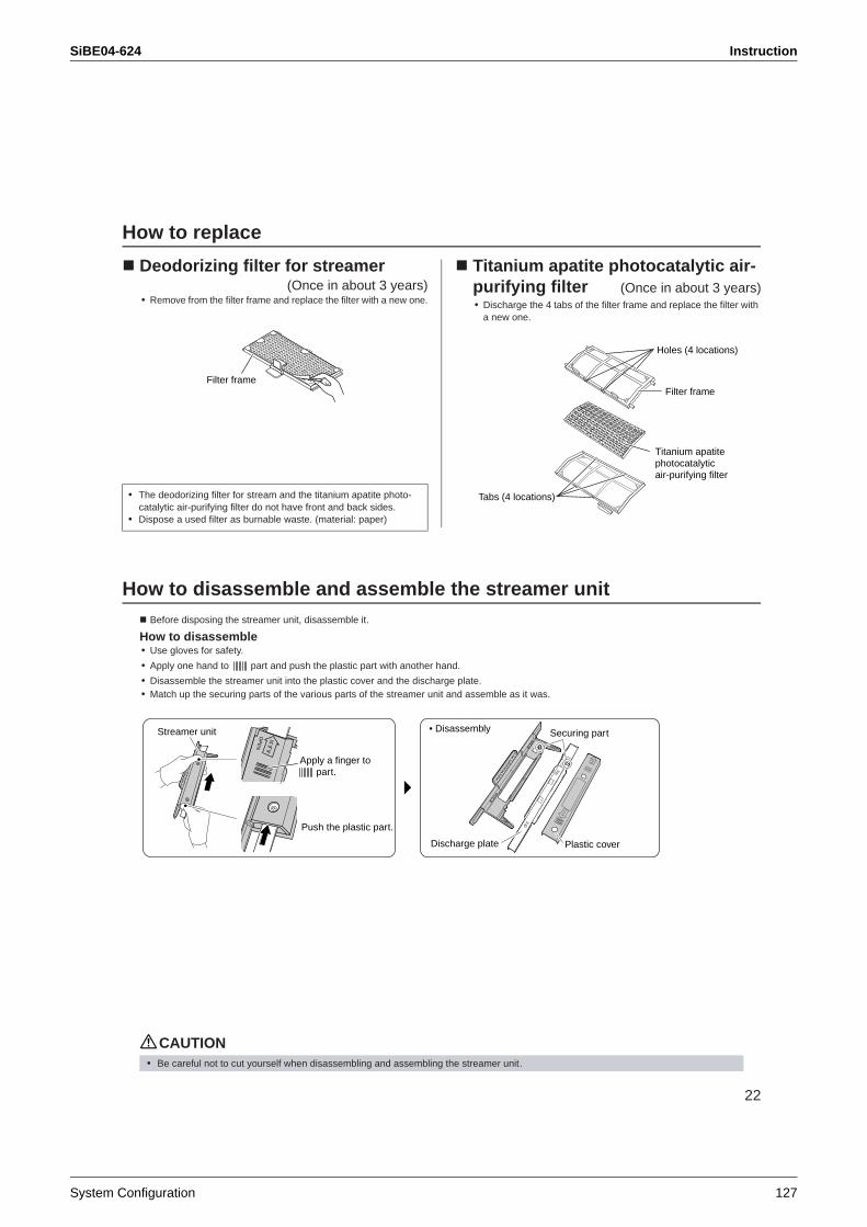
SiBE04-624 Instruction
System Configuration 127
22
How to replace
Deodorizing filter for streamer(Once in about 3 years)
• Remove from the filter frame and replace the filter with a new one.
Titanium apatite photocatalytic air-purifying filter (Once in about 3 years)• Discharge the 4 tabs of the filter frame and replace the filter with
a new one.
How to disassemble and assemble the streamer unitBefore disposing the streamer unit, disassemble it.
How to disassemble• Use gloves for safety.
• Apply one hand to part and push the plastic part with another hand.
• Disassemble the streamer unit into the plastic cover and the discharge plate.• Match up the securing parts of the various parts of the streamer unit and assemble as it was.
CAUTION
• The deodorizing filter for stream and the titanium apatite photo-catalytic air-purifying filter do not have front and back sides.
• Dispose a used filter as burnable waste. (material: paper)
Filter frame
Titanium apatite photocatalyticair-purifying filter
Filter frame
Holes (4 locations)
Tabs (4 locations)
OP
EN
Apply a finger to part.
Streamer unit
Push the plastic part.
• Disassembly
Discharge plate Plastic cover
Securing part
• Be careful not to cut yourself when disassembling and assembling the streamer unit.
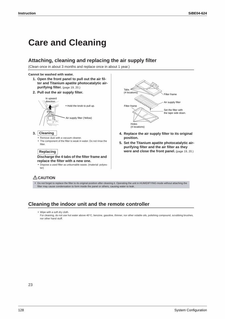
Instruction SiBE04-624
128 System Configuration
23
Care and Cleaning
Attaching, cleaning and replacing the air supply filter(Clean once in about 3 months and replace once in about 1 year.)
Cannot be washed with water.1. Open the front panel to pull out the air fil-
ter and Titanium apatite photocatalytic air-purifying filter. (page 19, 20.)
2. Pull out the air supply filter.
3.• Remove dust with a vacuum cleaner.• The component of the filter is weak in water. Do not rinse the
filter.
Discharge the 4 tabs of the filter frame and replace the filter with a new one.• Dispose a used filter as unburnable waste. (material: polyes-
ter)
4. Replace the air supply filter to its original position.
5. Set the Titanium apatite photocatalytic air-purifying filter and the air filter as they were and close the front panel. (page 19, 20.)
CAUTION
Cleaning the indoor unit and the remote controller• Wipe with a soft dry cloth.
For cleaning, do not use hot water above 40°C, benzine, gasoline, thinner, nor other volatile oils, polishing compound, scrubbing brushes, nor other hand stuff.
In upward direction
• Hold the knob to pull up.
Air supply filter (Yellow)
Cleaning
Replacing
Set the filter with the tape side down.
Holes(4 locations)
Tabs (4 locations)
Filter frame
Filter frameAir supply filter
• Do not forget to replace the filter to its original position after cleaning it. Operating the unit in HUMIDIFYING mode without attaching the filter may cause condensation to form inside the panel or others, causing water to leak.
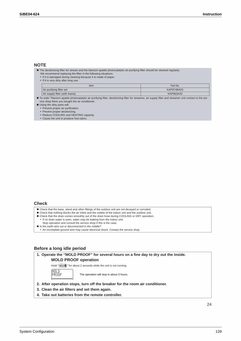
SiBE04-624 Instruction
System Configuration 129
24
NOTE
Check
Before a long idle period
The deodorizing filter for stream and the titanium apatite photocatalytic air-purifying filter should be cleaned regularly. We recommend replacing the filter in the following situations.• If it is damaged during cleaning because it is made of paper.• If it is very dirty after long use.
To order Titanium apatite photocatalytic air-purifying filter, deodorizing filter for streamer, air supply filter and streamer unit contact to the ser-vice shop there you bought the air conditioner.Using the dirty parts will:• Prevent proper air purification.• Prevent proper deodorizing.• Reduce COOLING and HEATING capacity.• Cause the unit to produce foul odors.
Check that the base, stand and other fittings of the outdoor unit are not decayed or corroded.Check that nothing blocks the air inlets and the outlets of the indoor unit and the outdoor unit.Check that the drain comes smoothly out of the drain hose during COOLING or DRY operation.• If no drain water is seen, water may be leaking from the indoor unit.
Stop operation and consult the service shop if this is the case.Is the earth wire out or disconnected in the middle?• An incomplete ground wire may cause electrical shock. Contact the service shop.
1. Operate the “MOLD PROOF” for several hours on a fine day to dry out the inside.MOLD PROOF operationHold “ ” for about 2 seconds while the unit is not running.
2. After operation stops, turn off the breaker for the room air conditioner.3. Clean the air filters and set them again.4. Take out batteries from the remote controller.
Item Part No.
Air purifying filter set KAF974B42S
Air supply filter (with frame) KAF963A43
The operation will stop in about 3 hours.
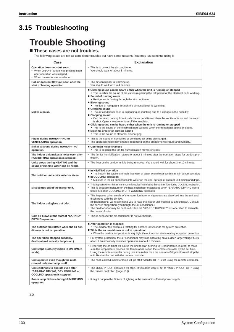
Instruction SiBE04-624
130 System Configuration
3.15 Troubleshooting
25
TROUBLE SHOOTING
Trouble ShootingThese cases are not troubles.The following cases are not air conditioner troubles but have some reasons. You may just continue using it.
Case ExplanationOperation does not start soon.• When ON/OFF button was pressed soon
after operation was stopped.• When the mode was reselected.
• This is to protect the air conditioner.You should wait for about 3 minutes.
Hot air does not flow out soon after the start of heating operation.
• The air conditioner is warming up. You should wait for 1 to 4 minutes.
Makes a noise.
Clicking sound can be heard either when the unit is running or stopped• This is either the sound of the valves regulating the refrigerant or the electrical parts working.Sound of running water• Refrigerant is flowing through the air conditioner.Blowing sound• The flow of refrigerant through the air conditioner is switching.Creaking sound• The air conditioner itself is expanding or shrinking due to a change in the humidity.Clopping sound• Can be heard coming from inside the air conditioner when the ventilator is on and the room
is shut. Open a window or turn off the ventilator.Clicking sound can be heard either when the unit is running or stopped• This is the sound of the electrical parts working when the front panel opens or closes.Blowing, cracky or burning sound• This is the sound of streamer discharging.
Fizzes during HUMIDIFYING or VENTILATING operation.
• This is the sound of humidified or ventilated air being discharged.• The operation noise may change depending on the outdoor temperature and humidity.
Makes a sound during HUMIDIFYING operation.
Operation noise changes• This is because the fan for humidification moves or stops.
The indoor unit makes a noise even after HUMIDIFYING operation is stopped.
• The fan for humidification rotates for about 3 minutes after the operation stops for product pro-tection.
Units stops during HEATING and the sound of running water can be heard.
• The frost on the outdoor unit is being removed. You should wait for about 3 to 10 minutes.
The outdoor unit emits water or steam.
In HEATING operation• The frost on the outdoor unit melts into water or steam when the air conditioner is in defrost operation.In COOLING operation• Moisture in the air condenses into water on the cool surface of outdoor unit piping and drips.
Mist comes out of the indoor unit.• This happens when the air in the room is cooled into mist by the cold air flow during COOLING operation.• This is because moisture on the heat exchanger evaporates when “SARARA” DRYING opera-
tion is run after COOLING or DRY COOLING operation.
The indoor unit gives out odor.
• This happens when smells of the room, furniture, or cigarettes are absorbed into the unit and discharged with the air flow.(If this happens, we recommend you to have the indoor unit washed by a technician. Consult the service shop where you bought the air conditioner.)
• The outdoor odor may be captured. Stop the “URURU” HUMIDIFYING operation to eliminate the cause of odor.
Cold air blows at the start of “SARARA” DRYING operation.
• This is because the air conditioner is not warmed up.
The outdoor fan rotates while the air con-ditioner is not in operation.
After operation is stopped:• The outdoor fan continues rotating for another 60 seconds for system protection.While the air conditioner is not in operation:• When the outdoor temperature is very high, the outdoor fan starts rotating for system protection.
The operation stopped suddenly.(Multi-colored indicator lamp is on.)
• For system protection, the air conditioner may stop operating on a sudden large voltage fluctu-ation. It automatically resumes operation in about 3 minutes.
Unit stops suddenly (when in ON TIMER mode).
• Reserving the on timer will cause the unit to start running up 1 hour before, in order to make sure the temperature reaches the temperature set on the remote controller by the set time. Using the remote controller during this time (other than the operation/stop button) will stop the unit. Restart the unit with the remote controller.
Unit operates even though the multi-colored indicator lamp is off.
• The multi-colored indicator lamp will go off if “Monitor OFF” is set using the remote controller.
Unit continues to operate even after “SARARA” DRYING, DRY COOLING or COOLING operation is stopped.
• The MOLD PROOF operation will start. (If you don’t want it, set to “MOLD PROOF OFF” using the remote controller. (page 15.))
Room lamp flickers during HUMIDIFYING operation.
• It might happen the flickers of lighting in the case of insufficient power supply.
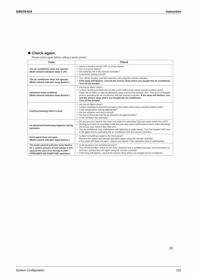
SiBE04-624 Instruction
System Configuration 131
26
Check again.Please check again before calling a repair person.
Case Check
The air conditioner does not operate.(Multi-colored indicator lamp is off.)
• Hasn’t a breaker turned OFF or a fuse blown?• Isn’t it a power failure?• Are batteries set in the remote controller?• Is the timer setting correct?
The air conditioner does not operate.(Multi-colored indicator lamp flashes.)
• Turn off the breaker and then start the unit using the remote controller.• If the lamp still flashes, consult the service shop where you bought the air conditioner.
Turn off the breaker.
Operation stops suddenly.(Multi-colored indicator lamp flashes.)
• Are the air filters clean?• Is there anything to block the air inlet or the outlet of the indoor and the outdoor units?
Clean the air filters or take all obstacles away and turn the breaker OFF. Then turn it ON again and try operating the air conditioner with the remote controller. If the lamp still flashes, con-sult the service shop where you bought the air conditioner.Turn off the breaker.
Cooling (Heating) effect is poor.
• Are the air filters clean?• Is there anything to block the air inlet or the outlet of the indoor and the outdoor units?• Is the temperature setting appropriate?• Are the windows and doors closed?• Are the air flow rate and the air direction set appropriately?• Is the ventilator fan spinning?
An abnormal functioning happens during operation.
• Do you put your hand in the main unit while it is operating? (Do you touch inside the unit?)• Putting your hand (or touching) inside the unit may cause malfunctions due to static discharge.
Do not put your hand in the main unit.• The air conditioner may malfunction with lightning or radio waves. Turn the breaker OFF, turn
it ON again and try operating the air conditioner with the remote controller.
Front panel does not open.(Multi-colored indicator lamp flashes.)
• Is there something caught in the front panel?Remove the object and attempt operation again using the remote controller. If the panel still does not open, contact your dealer if the operation lamp is still flashing.
The multi-colored indicator lamp flashes for a certain amount of time (about 2 min-utes) at the start of or during FLASH STREAMER AIR PURIFYING operation.
• Is the streamer unit installed securely?• Turn off the breaker, check to see if the streamer unit is installed securely, turn the power on,
and then operate the unit again using the remote controller.• If the lamp still flashes, consult the service shop where you bought the air conditioner.
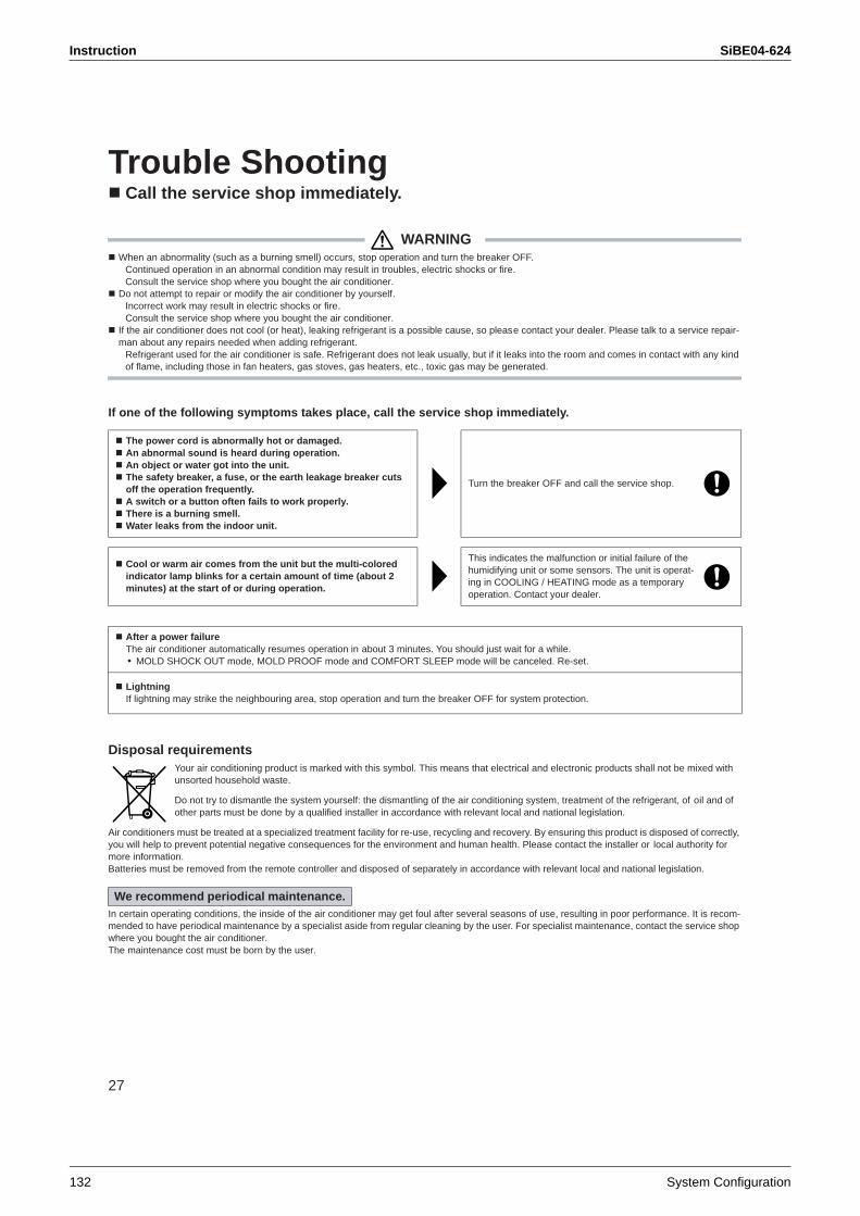
Instruction SiBE04-624
132 System Configuration
27
Trouble ShootingCall the service shop immediately.
WARNINGWhen an abnormality (such as a burning smell) occurs, stop operation and turn the breaker OFF.
Continued operation in an abnormal condition may result in troubles, electric shocks or fire.Consult the service shop where you bought the air conditioner.
Do not attempt to repair or modify the air conditioner by yourself.Incorrect work may result in electric shocks or fire.Consult the service shop where you bought the air conditioner.
If the air conditioner does not cool (or heat), leaking refrigerant is a possible cause, so please contact your dealer. Please talk to a service repair-man about any repairs needed when adding refrigerant.
Refrigerant used for the air conditioner is safe. Refrigerant does not leak usually, but if it leaks into the room and comes in contact with any kind of flame, including those in fan heaters, gas stoves, gas heaters, etc., toxic gas may be generated.
If one of the following symptoms takes place, call the service shop immediately.
Disposal requirementsYour air conditioning product is marked with this symbol. This means that electrical and electronic products shall not be mixed with unsorted household waste.
Do not try to dismantle the system yourself: the dismantling of the air conditioning system, treatment of the refrigerant, of oil and of other parts must be done by a qualified installer in accordance with relevant local and national legislation.
Air conditioners must be treated at a specialized treatment facility for re-use, recycling and recovery. By ensuring this product is disposed of correctly, you will help to prevent potential negative consequences for the environment and human health. Please contact the installer or local authority for more information. Batteries must be removed from the remote controller and disposed of separately in accordance with relevant local and national legislation.
In certain operating conditions, the inside of the air conditioner may get foul after several seasons of use, resulting in poor performance. It is recom-mended to have periodical maintenance by a specialist aside from regular cleaning by the user. For specialist maintenance, contact the service shop where you bought the air conditioner.The maintenance cost must be born by the user.
The power cord is abnormally hot or damaged.An abnormal sound is heard during operation.An object or water got into the unit.The safety breaker, a fuse, or the earth leakage breaker cuts off the operation frequently. A switch or a button often fails to work properly.There is a burning smell.Water leaks from the indoor unit.
Turn the breaker OFF and call the service shop.
Cool or warm air comes from the unit but the multi-colored indicator lamp blinks for a certain amount of time (about 2 minutes) at the start of or during operation.
This indicates the malfunction or initial failure of the humidifying unit or some sensors. The unit is operat-ing in COOLING / HEATING mode as a temporary operation. Contact your dealer.
After a power failureThe air conditioner automatically resumes operation in about 3 minutes. You should just wait for a while.• MOLD SHOCK OUT mode, MOLD PROOF mode and COMFORT SLEEP mode will be canceled. Re-set.
LightningIf lightning may strike the neighbouring area, stop operation and turn the breaker OFF for system protection.
We recommend periodical maintenance.
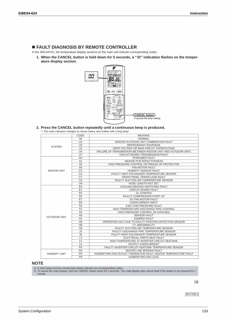
SiBE04-624 Instruction
System Configuration 133
28
FAULT DIAGNOSIS BY REMOTE CONTROLLERIn the ARC447A1, the temperature display sections on the main unit indicate corresponding codes.
1. When the CANCEL button is held down for 5 seconds, a “ ” indication flashes on the temper-ature display section.
2. Press the CANCEL button repeatedly until a continuous beep is produced. • The code indication changes as shown below, and notifies with a long beep.
NOTE
CODE MEANING
SYSTEM
00 NORMALUA INDOOR-OUTDOOR UNIT COMBINATION FAULTU0 REFRIGERANT SHORTAGEU2 DROP VOLTAGE OR MAIN CIRCUIT OVERVOLTAGEU4 FAILURE OF TRANSMISSION (BETWEEN INDOOR UNIT AND OUTDOOR UNIT)U7 CIRCUIT BOARD TRANSMISSION FAULT
INDOOR UNIT
AH STREAMER FAULTA1 INDOOR PCB DEFECTIVENESSA5 HIGH PRESSURE CONTROL OR FREEZE-UP PROTECTORA6 FAN MOTOR FAULTCC HUMIDITY SENSOR FAULTC4 FAULTY HEAT EXCHANGER TEMPERATURE SENSORC7 FRONT PANEL OPEN/CLOSE FAULTC9 FAULTY SUCTION AIR TEMPERATURE SENSORUA HOSE LENGTH NOT SET
OUTDOOR UNIT
EA COOLING-HEATING SWITCHING FAULTE1 CIRCUIT BOARD FAULTE5 OL STARTEDE6 FAULTY COMPRESSOR START UPE7 DC FAN MOTOR FAULTE8 OVERCURRENT INPUTFA EJECTION PRESSURE FAULTF3 HIGH TEMPERATURE DISCHARGE PIPE CONTROLF6 HIGH PRESSURE CONTROL (IN COOLING)H0 SENSOR FAULTH1 DAMPER FAULTH6 OPERATION HALT DUE TO FAULTY POSITION DETECTION SENSORH8 CT ABNORMALITYH9 FAULTY SUCTION AIR TEMPERATURE SENSORJ3 FAULTY DISCHARGE PIPE TEMPERATURE SENSORJ6 FAULTY HEAT EXCHANGER TEMPERATURE SENSORL3 ELECTRICAL PARTS HEAT FAULTL4 HIGH TEMPERATURE AT INVERTER CIRCUIT HEATSINKL5 OUTPUT OVERCURRENTP4 FAULTY INVERTER CIRCUIT HEATSINK TEMPERATURE SENSOR
HUMIDIFY UNITPA HEATER LINE BROKEN FAULTPH HUMIDIFYING FAN OUTLET THERMISTOR FAULT, HEATER TEMPERATURE FAULTP9 HUMIDIFYING FAN LOCK
1) A short beep and two consecutive beeps indicate non-corresponding codes.2) To cancel the code display, hold the CANCEL button down for 5 seconds. The code display also cancel itself if the button is not pressed for 1
minute.
CANCEL buttonIt cancels the timer setting.
3P177300-1
Instruction SiBE04-624
134 System Configuration
SiBE04-624
Service Diagnosis 135
Part 6 Service Diagnosis
1. Convenient Service Check Function ...................................................1372. Troubleshooting ..................................................................................139
2.1 Error Code Indication by Remote Controller ........................................1392.2 Air conditioner does not run. ................................................................1412.3 Air conditioner runs but does not get cooling (heating). .......................1432.4 When operation starts, safety breaker works. ......................................1452.5 Air conditioner makes big noise and vibration......................................1472.6 Air does not humidified enough............................................................1482.7 Indoor Unit PCB Fault ..........................................................................1502.8 Peak-cut Control or Freeze-up Protection............................................1512.9 Fan Motor System (DC Motor) Fault ....................................................1532.10 Streamer Unit Fault ..............................................................................1552.11 Thermistor System Fault ......................................................................1572.12 Front Panel Open / Close Fault............................................................1582.13 Humidity Sensor Fault ..........................................................................1592.14 Signal Transmission Error (Indoor Unit - Outdoor Unit) .......................1602.15 Incompatible Power Supply between Indoor Unit and Outdoor Unit ....1622.16 Incomplete Setting for Hose Length .....................................................1632.17 Outdoor Unit PCB Fault........................................................................1642.18 OL Activation (Compressor Overload) .................................................1652.19 Compressor Lock .................................................................................1662.20 DC Fan Lock ........................................................................................1672.21 Input Over Current Detection ...............................................................1682.22 Four Way Valve Fault...........................................................................1702.23 Discharge Pipe Temperature Control...................................................1722.24 High Pressure Control in Cooling .........................................................1732.25 Compressor Sensor System Fault .......................................................1752.26 Damper Fault........................................................................................1762.27 Position Sensor Fault ...........................................................................1772.28 DC Voltage / DC Current Sensor Fault ................................................1792.29 Thermistor System Fault ......................................................................1802.30 Abnormal Temperature in Electrical Box..............................................1822.31 Temperature Rise in Radiation Fin.......................................................1842.32 Output Overcurrent...............................................................................1862.33 Insufficient Gas.....................................................................................1882.34 Over Voltage Protection / Low Voltage Protection ...............................1902.35 Outdoor Unit PCB Fault or Communication Circuit Fault .....................1912.36 Signal Transmission Error on Outdoor Unit PCB .................................1942.37 Fan Motor System Fault / Fan Lock .....................................................1962.38 Heater Wire Fault .................................................................................1972.39 Humidification Fan Outlet Thermistor Fault /
Abnormal Heater Temperature.............................................................1992.40 Lights-out of Microcomputer Status Lamp............................................201
3. Check ..................................................................................................2023.1 Thermistor Resistance Check ..............................................................202
SiBE04-624
136 Service Diagnosis
3.2 Installation Condition Check.................................................................2033.3 Outdoor Fan System Check (DC Motor) ..............................................2033.4 Power Supply Waveform Check...........................................................2043.5 Capacitor Voltage Check......................................................................2043.6 Main Circuit Electrolytic Capacitor Check ............................................2053.7 Refrigerant System Check ...................................................................2053.8 “Inverter Checker” Check .....................................................................2063.9 Power Transistor Check .......................................................................2073.10 Discharge Pressure Check...................................................................2083.11 Electronic Expansion Valve Check.......................................................2093.12 Indoor Unit PCB Output Check ............................................................2103.13 Rotating Pulse Input on Outdoor Unit PCB Check ...............................2113.14 Humidity Sensor Check........................................................................2123.15 Main Circuit Short Check......................................................................2123.16 Four-way Valve Performance Check....................................................2133.17 Solenoid Valve for Dehumidification Check .........................................214
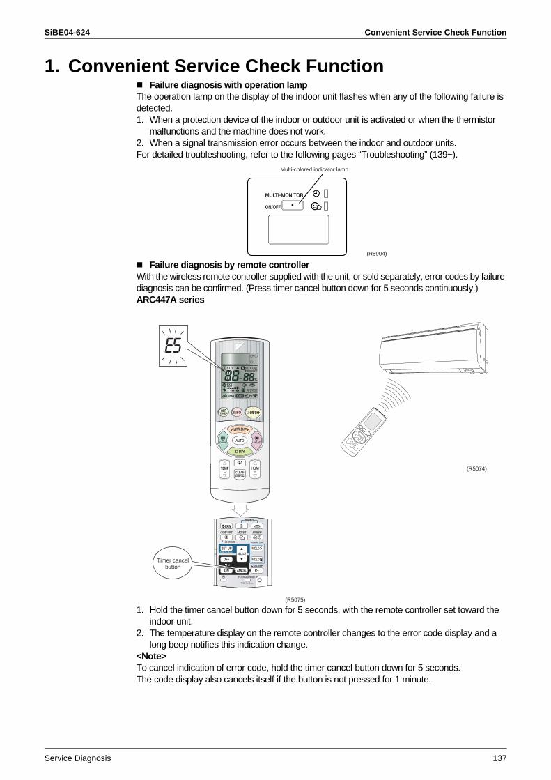
SiBE04-624 Convenient Service Check Function
Service Diagnosis 137
1. Convenient Service Check FunctionFailure diagnosis with operation lamp
The operation lamp on the display of the indoor unit flashes when any of the following failure is detected.1. When a protection device of the indoor or outdoor unit is activated or when the thermistor
malfunctions and the machine does not work.2. When a signal transmission error occurs between the indoor and outdoor units.For detailed troubleshooting, refer to the following pages “Troubleshooting” (139~).
Failure diagnosis by remote controllerWith the wireless remote controller supplied with the unit, or sold separately, error codes by failure diagnosis can be confirmed. (Press timer cancel button down for 5 seconds continuously.)ARC447A series
1. Hold the timer cancel button down for 5 seconds, with the remote controller set toward the indoor unit.
2. The temperature display on the remote controller changes to the error code display and a long beep notifies this indication change.
<Note>To cancel indication of error code, hold the timer cancel button down for 5 seconds.The code display also cancels itself if the button is not pressed for 1 minute.
Multi-colored indicator lamp
(R5904)
E5
(R5075)
Timer cancel button
(R5074)
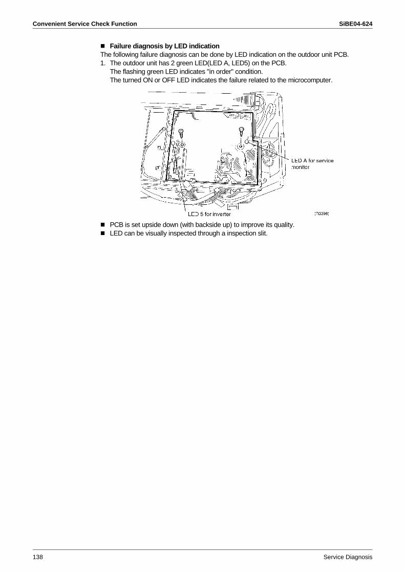
Convenient Service Check Function SiBE04-624
138 Service Diagnosis
Failure diagnosis by LED indicationThe following failure diagnosis can be done by LED indication on the outdoor unit PCB.1. The outdoor unit has 2 green LED(LED A, LED5) on the PCB.
The flashing green LED indicates "in order" condition.The turned ON or OFF LED indicates the failure related to the microcomputer.
PCB is set upside down (with backside up) to improve its quality.LED can be visually inspected through a inspection slit.
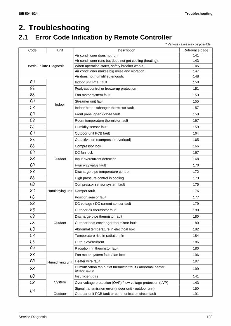
SiBE04-624 Troubleshooting
Service Diagnosis 139
2. Troubleshooting2.1 Error Code Indication by Remote Controller
* Various cases may be possible.
Code Unit Description Reference page
Basic Failure Diagnosis
Air conditioner does not run. 141
Air conditioner runs but does not get cooling (heating). 143
When operation starts, safety breaker works. 145
Air conditioner makes big noise and vibration. 147
Air does not humidified enough. 148
A1
Indoor
Indoor unit PCB fault 150
A5 Peak-cut control or freeze-up protection 151
A6 Fan motor system fault 153
AH Streamer unit fault 155
C4 Indoor heat exchanger thermistor fault 157
C7 Front panel open / close fault 158
C9 Room temperature thermistor fault 157
CC Humidity sensor fault 159
E1
Outdoor
Outdoor unit PCB fault 164
E5 OL activation (compressor overload) 165
E6 Compressor lock 166
E7 DC fan lock 167
E8 Input overcurrent detection 168
EA Four way valve fault 170
F3 Discharge pipe temperature control 172
F6 High pressure control in cooling 173
H0 Compressor sensor system fault 175
H1 Humidifying unit Damper fault 176
H6
Outdoor
Position sensor fault 177
H8 DC voltage / DC current sensor fault 179
H9 Outdoor air thermistor fault 180
J3 Discharge pipe thermistor fault 180
J6 Outdoor heat exchanger thermistor fault 180
L3 Abnormal temperature in electrical box 182
L4 Temperature rise in radiation fin 184
L5 Output overcurrent 186
P4 Radiation fin thermistor fault 180
P9
Humidifying unit
Fan motor system fault / fan lock 196
PA Heater wire fault 197
PH Humidification fan outlet thermistor fault / abnormal heater temperature 199
U0
System
Insufficient gas 141
U2 Over voltage protection (OVP) / low voltage protection (LVP) 143
U4Signal transmission error (indoor unit - outdoor unit) 160
Outdoor Outdoor unit PCB fault or communication circuit fault 191
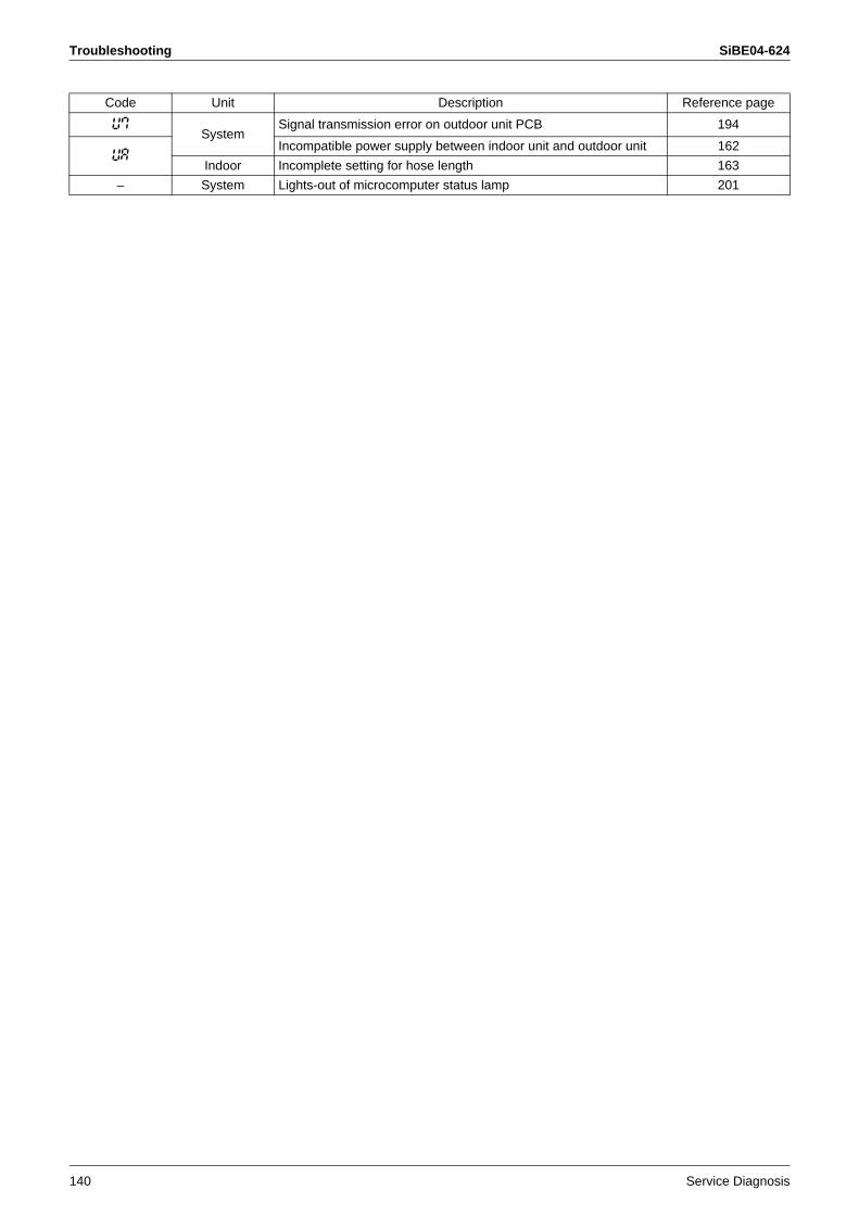
Troubleshooting SiBE04-624
140 Service Diagnosis
U7System
Signal transmission error on outdoor unit PCB 194
UAIncompatible power supply between indoor unit and outdoor unit 162
Indoor Incomplete setting for hose length 163
– System Lights-out of microcomputer status lamp 201
Code Unit Description Reference page
SiBE04-624 Troubleshooting
Service Diagnosis 141
2.2 Air conditioner does not run.
Method of Malfunction Detection
Malfunction Decision Conditions
Supposed Causes
Power supply is OFFImproper power supply voltageImproper connection of wireIncorrect combination of indoor unit and outdoor unitBattery shortage of remote controllerInvalid address settingProtection device works(dirty air filter, insufficient gas, over filling, mixed air, etc.)Transmission error between indoor unit and outdoor unit(Defective PCB on outdoor unit)
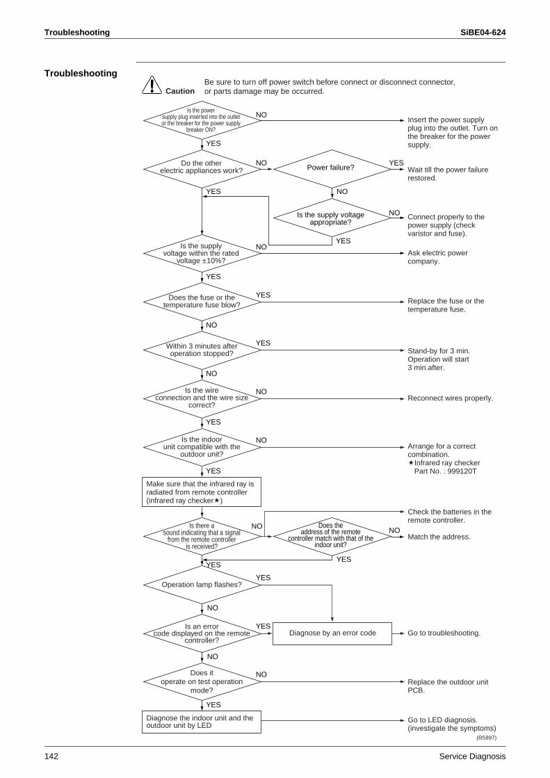
Troubleshooting SiBE04-624
142 Service Diagnosis
Troubleshooting
YES
YES
YES
YES
Insert the power supply plug into the outlet. Turn on the breaker for the power supply.
Wait till the power failure restored.
Connect properly to the power supply (check varistor and fuse).
Ask electric power company.
Replace the fuse or the temperature fuse.
Stand-by for 3 min.Operation will start3 min.after.
Reconnect wires properly.
Arrange for a correct combination.
Infrared ray checkerPart No. : 999120T
Check the batteries in the remote controller.
Match the address.
Go to troubleshooting.
Replace the outdoor unit PCB.
Go to LED diagnosis.(investigate the symptoms)
Is the powersupply plug inserted into the outletor the breaker for the power supply
breaker ON?
(R5997)
CautionBe sure to turn off power switch before connect or disconnect connector, or parts damage may be occurred.
Do the otherelectric appliances work?
Is the supplyvoltage within the rated
voltage ±10%?
NO
NO
NO
NO
NO YES
NO
NO
YES
YES
Does the fuse or the temperature fuse blow?
NO
Within 3 minutes after operation stopped?
NO
Is the wireconnection and the wire size
correct?
YES
Is the indoorunit compatible with the
outdoor unit?
YES
YES
NO
NO
YES
Is there asound indicating that a signal
from the remote controlleris received?
YESYES
Operation lamp flashes?
Is an errorcode displayed on the remote
controller?
NODoes itoperate on test operation
mode?
Power failure?
Is the supply voltage appropriate?
NO NODoes the
address of the remotecontroller match with that of the
indoor unit?
Make sure that the infrared ray is radiated from remote controller (infrared ray checker )
YES
Diagnose the indoor unit and the outdoor unit by LED
Diagnose by an error code
SiBE04-624 Troubleshooting
Service Diagnosis 143
2.3 Air conditioner runs but does not get cooling (heating).
Method of Malfunction Detection
Malfunction Decision Conditions
Supposed Causes
Incorrect temperature settingIncorrect combination of indoor unit and outdoor unitBlocked air filterInsufficient powerRefrigerant piping is too longImproper setting of piping lengthDefective field piping (squeezed, etc.)
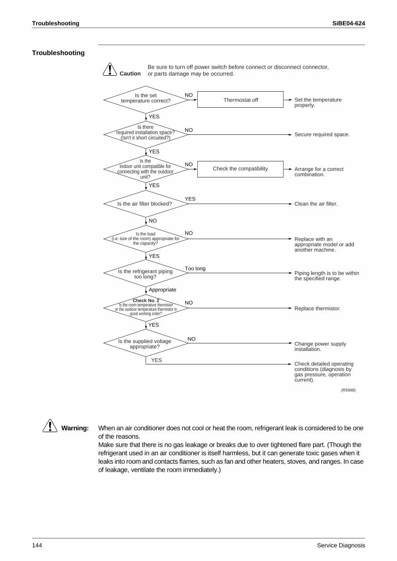
Troubleshooting SiBE04-624
144 Service Diagnosis
Troubleshooting
Warning: When an air conditioner does not cool or heat the room, refrigerant leak is considered to be one of the reasons.Make sure that there is no gas leakage or breaks due to over tightened flare part. (Though the refrigerant used in an air conditioner is itself harmless, but it can generate toxic gases when it leaks into room and contacts flames, such as fan and other heaters, stoves, and ranges. In case of leakage, ventilate the room immediately.)
Set the temperature properly.
Secure required space.
Arrange for a correct combination.
Clean the air filter.
Replace with an appropriate model or add another machine.
Piping length is to be within the specified range.
Replace thermistor.
Change power supply installation.
Check detailed operating conditions (diagnosis by gas pressure, operation current).
Is the settemperature correct?
Is the supplied voltage appropriate?
(R5998)
YES
NO
CautionBe sure to turn off power switch before connect or disconnect connector, or parts damage may be occurred.
Is thererequired installation space?
(Isn't it short circuited?)
Thermostat off
Check the compatibility.
Is theindoor unit compatible for
connecting with the outdoorunit?
NO
NO
NO
NO
NO
YES
YES
YES
YES
YES
Appropriate
NO
Is the air filter blocked?
YES
Is the load(i.e. size of the room) appropriate for
the capacity?
Is the refrigerant piping too long?
Too long
Check No. 2Is the room temperature thermistor
or the outdoor temperature thermistor ingood working order?
SiBE04-624 Troubleshooting
Service Diagnosis 145
2.4 When operation starts, safety breaker works.
Method of Malfunction Detection
Malfunction Decision Conditions
Supposed Causes
Insufficient capacity of safety breakerEarth leakage breaker is too sensitiveNot exclusive circuitThe supply voltage is not within rated voltage ±10%.The size of connecting wire is thin (indoor power supply unit)Air is mixed (over filling)Damaged outdoor unit PCB (short circuit)
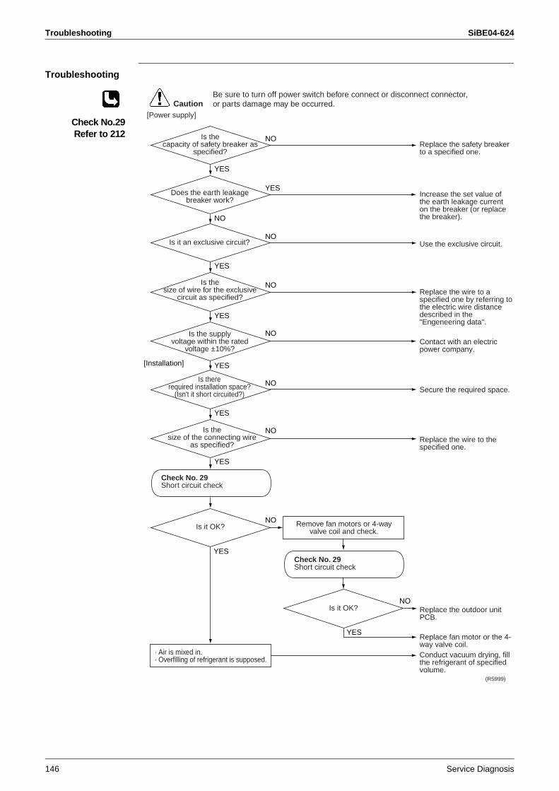
Troubleshooting SiBE04-624
146 Service Diagnosis
Troubleshooting
Check No.29Refer to 212
Replace the safety breaker to a specified one.
Increase the set value of the earth leakage current on the breaker (or replace the breaker).
Use the exclusive circuit.
Replace the wire to a specified one by referring to the electric wire distance described in the "Engeneering data".
Contact with an electric power company.
Secure the required space.
Replace the wire to the specified one.
Replace the outdoor unit PCB.
Replace fan motor or the 4-way valve coil.Conduct vacuum drying, fill the refrigerant of specified volume.
Is thecapacity of safety breaker as
specified?
(R5999)
CautionBe sure to turn off power switch before connect or disconnect connector, or parts damage may be occurred.
Does the earth leakage breaker work?
Remove fan motors or 4-way valve coil and check.
· Air is mixed in.· Overfilling of refrigerant is supposed.
Is it an exclusive circuit?NO
NO
NO
NO
NO
YES
NO
NO
YES
NO
YES
YES[Installation]
YES
YES
YES
Is thesize of wire for the exclusive
circuit as specified?
YES
Is the supplyvoltage within the rated
voltage ±10%?
Is thererequired installation space?
(Isn't it short circuited?)
NO
Is thesize of the connecting wire
as specified?
Is it OK?
Is it OK?
Check No. 29Short circuit check
YES
Check No. 29Short circuit check
[Power supply]
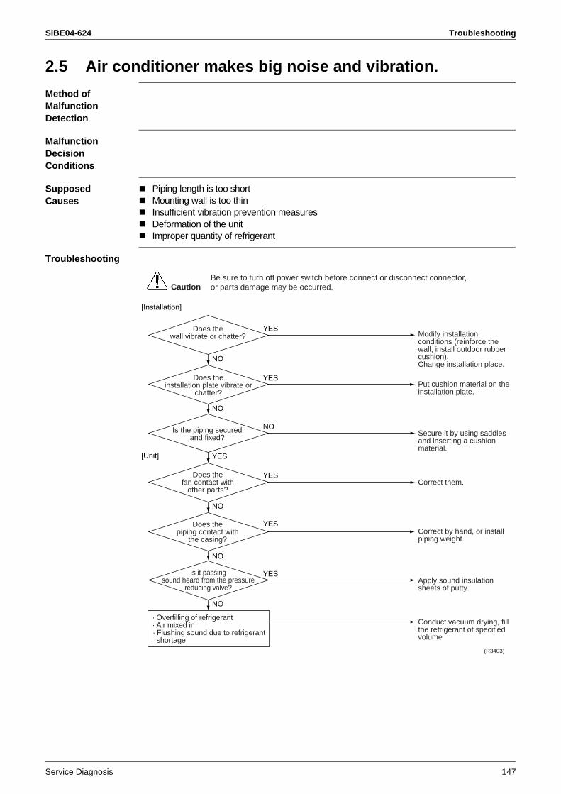
SiBE04-624 Troubleshooting
Service Diagnosis 147
2.5 Air conditioner makes big noise and vibration.
Method of Malfunction Detection
Malfunction Decision Conditions
Supposed Causes
Piping length is too shortMounting wall is too thinInsufficient vibration prevention measuresDeformation of the unitImproper quantity of refrigerant
Troubleshooting
Modify installation conditions (reinforce the wall, install outdoor rubber cushion).Change installation place.
Put cushion material on the installation plate.
Secure it by using saddles and inserting a cushion material.
Correct them.
Correct by hand, or install piping weight.
Apply sound insulation sheets of putty.
Conduct vacuum drying, fill the refrigerant of specified volume
Does thewall vibrate or chatter?
(R3403)
CautionBe sure to turn off power switch before connect or disconnect connector, or parts damage may be occurred.
Does theinstallation plate vibrate or
chatter?
· Overfilling of refrigerant· Air mixed in· Flushing sound due to refrigerant shortage
Is the piping securedand fixed?
NO
YES
YES
YES
YES
NO
NO
YES
NO
[Unit]
[Installation]
NO
NO
Does thefan contact with
other parts?
Does thepiping contact with
the casing?
Is it passingsound heard from the pressure
reducing valve?
YES
Troubleshooting SiBE04-624
148 Service Diagnosis
2.6 Air does not humidified enough.
Method of Malfunction Detection
Malfunction Decision Conditions
Supposed Causes
Hose length is not setIncorrect settingShort circuited at outdoor unitBlocked humidification filterInsufficient heat insulation of ductIndoor ventilation is made too often Ceiling is very high.
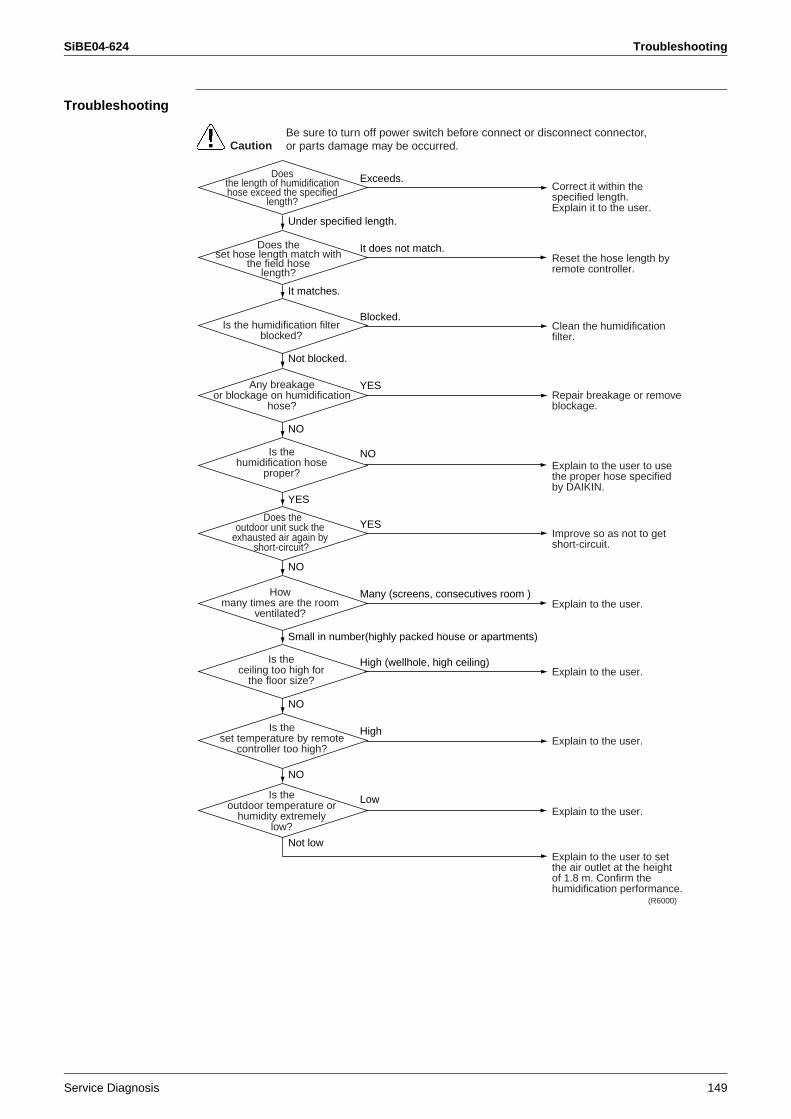
SiBE04-624 Troubleshooting
Service Diagnosis 149
Troubleshooting
Correct it within the specified length.Explain it to the user.
Reset the hose length by remote controller.
Clean the humidification filter.
Repair breakage or remove blockage.
Explain to the user to use the proper hose specified by DAIKIN.
Improve so as not to get short-circuit.
Explain to the user.
Explain to the user.
Explain to the user.
Explain to the user.
Explain to the user to set the air outlet at the height of 1.8 m. Confirm the humidification performance.
Doesthe length of humidificationhose exceed the specified
length?
(R6000)
CautionBe sure to turn off power switch before connect or disconnect connector, or parts damage may be occurred.
Does theset hose length match with
the field hoselength?
Is the humidification filter blocked?
Blocked.
NO
It does not match.
Exceeds.
YES
Under specified length.
It matches.
Not blocked.
YES
NO
Any breakageor blockage on humidification
hose?
Is thehumidification hose
proper?
Does theoutdoor unit suck the
exhausted air again by short-circuit?
YES
Howmany times are the room
ventilated?
Is theceiling too high for
the floor size?
High (wellhole, high ceiling)
Low
Many (screens, consecutives room )
High
NO
Small in number(highly packed house or apartments)
NO
Not low
NO
Is theset temperature by remote
controller too high?
Is theoutdoor temperature or
humidity extremelylow?
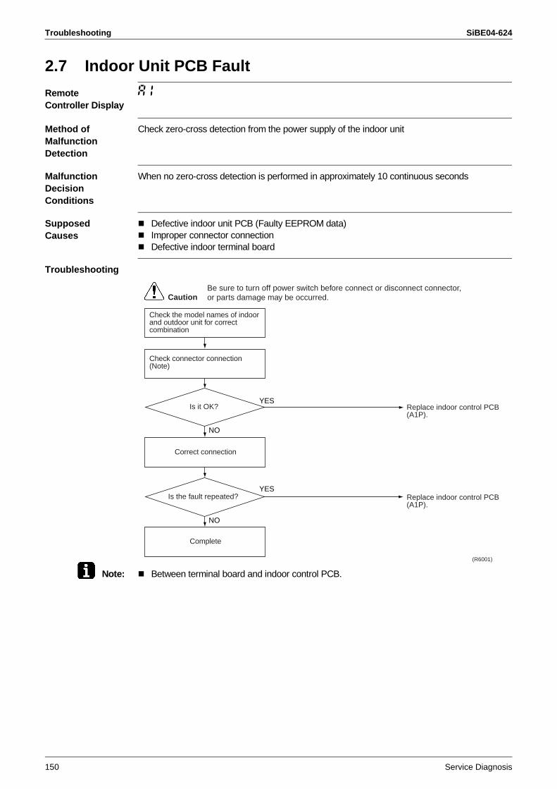
Troubleshooting SiBE04-624
150 Service Diagnosis
2.7 Indoor Unit PCB Fault
Remote Controller Display
A1
Method of Malfunction Detection
Check zero-cross detection from the power supply of the indoor unit
Malfunction Decision Conditions
When no zero-cross detection is performed in approximately 10 continuous seconds
Supposed Causes
Defective indoor unit PCB (Faulty EEPROM data)Improper connector connectionDefective indoor terminal board
Troubleshooting
Note: Between terminal board and indoor control PCB.
Replace indoor control PCB (A1P).
Replace indoor control PCB (A1P).
(R6001)
CautionBe sure to turn off power switch before connect or disconnect connector, or parts damage may be occurred.
Complete
Check the model names of indoor and outdoor unit for correct combination
Check connector connection (Note)
Correct connection
Is it OK?YES
YES
NO
NO
Is the fault repeated?
SiBE04-624 Troubleshooting
Service Diagnosis 151
2.8 Peak-cut Control or Freeze-up Protection
Remote Controller Display
A5
Method of Malfunction Detection
Peak-cut control (high pressure control)During heating operation, the temperature detected by the indoor heat exchanger thermistor is used for the high pressure control (stop, outdoor fan stop, etc.).Freeze-up protection control (operation halt) is activated during cooling operation according to the temperature detected by the indoor heat exchanger thermistor.
Malfunction Decision Conditions
Peak-cut controlOn heating operation, when indoor heat exchanger temperature is about 65°C or moreFreeze-up protectionOn cooling operation, indoor heat exchanger temperature is 0°C or less
Supposed Causes
Halt due to dirty indoor unit filterHalt due to dirty indoor heat exchangerHalt due to short circuitFaulty detection due to defective indoor heat exchanger thermistorReheating dehumidification solenoid valve remains closed (on cooling operation)Faulty detection due to defective indoor unit PCB
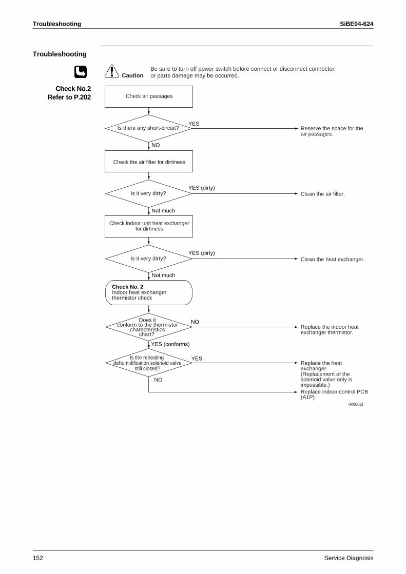
Troubleshooting SiBE04-624
152 Service Diagnosis
Troubleshooting
Check No.2Refer to P.202
Reserve the space for the air passages.
Clean the air filter.
Clean the heat exchanger.
Replace the indoor heat exchanger thermistor.
Replace the heat exchanger.(Replacement of the solenoid valve only is impossible.)Replace indoor control PCB (A1P)
(R6002)
CautionBe sure to turn off power switch before connect or disconnect connector, or parts damage may be occurred.
Check indoor unit heat exchanger for dirtiness
Check air passages
Check the air filter for dirtiness
Is there any short-circuit?YES
YES (dirty)
NO
Not much
Is it very dirty?
YES (dirty)Is it very dirty?
Not much
Is the reheating dehumidification solenoid valve
still closed?
NO
YES
Check No. 2Indoor heat exchanger thermistor check
NODoes itconform to the thermistor
characteristicschart?
YES (conforms)
SiBE04-624 Troubleshooting
Service Diagnosis 153
2.9 Fan Motor System (DC Motor) Fault
Remote Controller Display
A6
Method of Malfunction Detection
The fan speed detected by the Hall IC during operation of high-pressure fan motor is used to determine abnormal fan operation.
Malfunction Decision Conditions
When the detected fan speed is less than 50% of the HH tap under maximum fan motor rpm demanded
Supposed Causes
Halt due to rare short circuit inside the fan motorHalt due to breakage of wire inside the fan motorHalt due to breakage of the lead wire of fan motorFaulty detection due to defective indoor control PCB
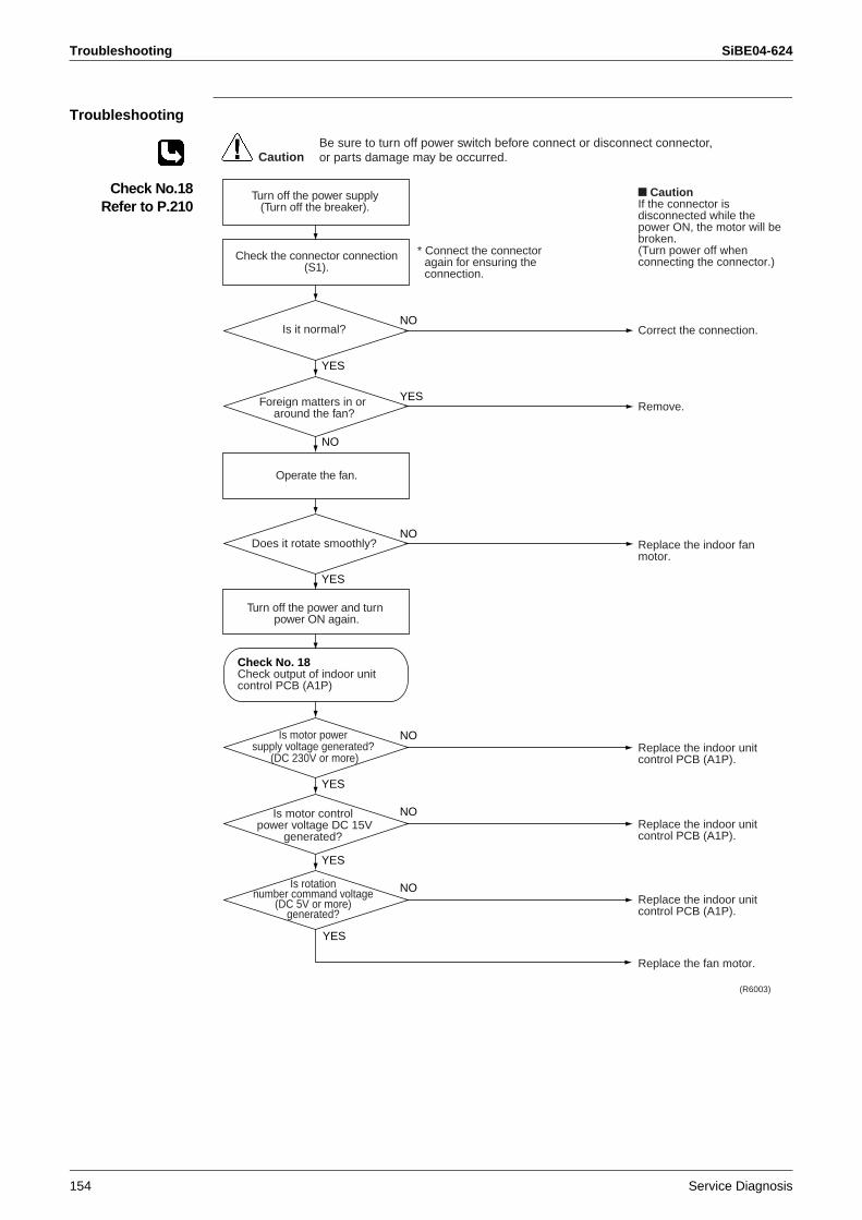
Troubleshooting SiBE04-624
154 Service Diagnosis
Troubleshooting
Check No.18Refer to P.210
Correct the connection.
Remove.
Replace the indoor fan motor.
Replace the indoor unit control PCB (A1P).
Replace the indoor unit control PCB (A1P).
Replace the indoor unit control PCB (A1P).
Replace the fan motor.
CautionIf the connector is disconnected while the power ON, the motor will be broken.(Turn power off when connecting the connector.)
(R6003)
CautionBe sure to turn off power switch before connect or disconnect connector, or parts damage may be occurred.
Turn off the power supply (Turn off the breaker).
Is it normal?NO
NO
YES
YES
Foreign matters in or around the fan?
YES
NO
Does it rotate smoothly?NO
YES
Check the connector connection (S1).
* Connect the connector again for ensuring the connection.
Operate the fan.
Turn off the power and turn power ON again.
Is motor power supply voltage generated?
(DC 230V or more)
NO
YES
Is motor control power voltage DC 15V
generated?
NOIs rotation number command voltage
(DC 5V or more) generated?
YES
Check No. 18Check output of indoor unit control PCB (A1P)
SiBE04-624 Troubleshooting
Service Diagnosis 155
2.10 Streamer Unit Fault
Remote Controller Display
AH
Method of Malfunction Detection
Malfunction Decision Conditions
If the error repeats 3 times in air purifying operation.Clearing condition: Continuous run for about 2 minutes (normal).
Supposed Causes
Short circuit caused by the dust or drip of water on the streamer unit electrode part. Scratch or crack in the harness for the streamer unit.Faulty indoor unit PCB
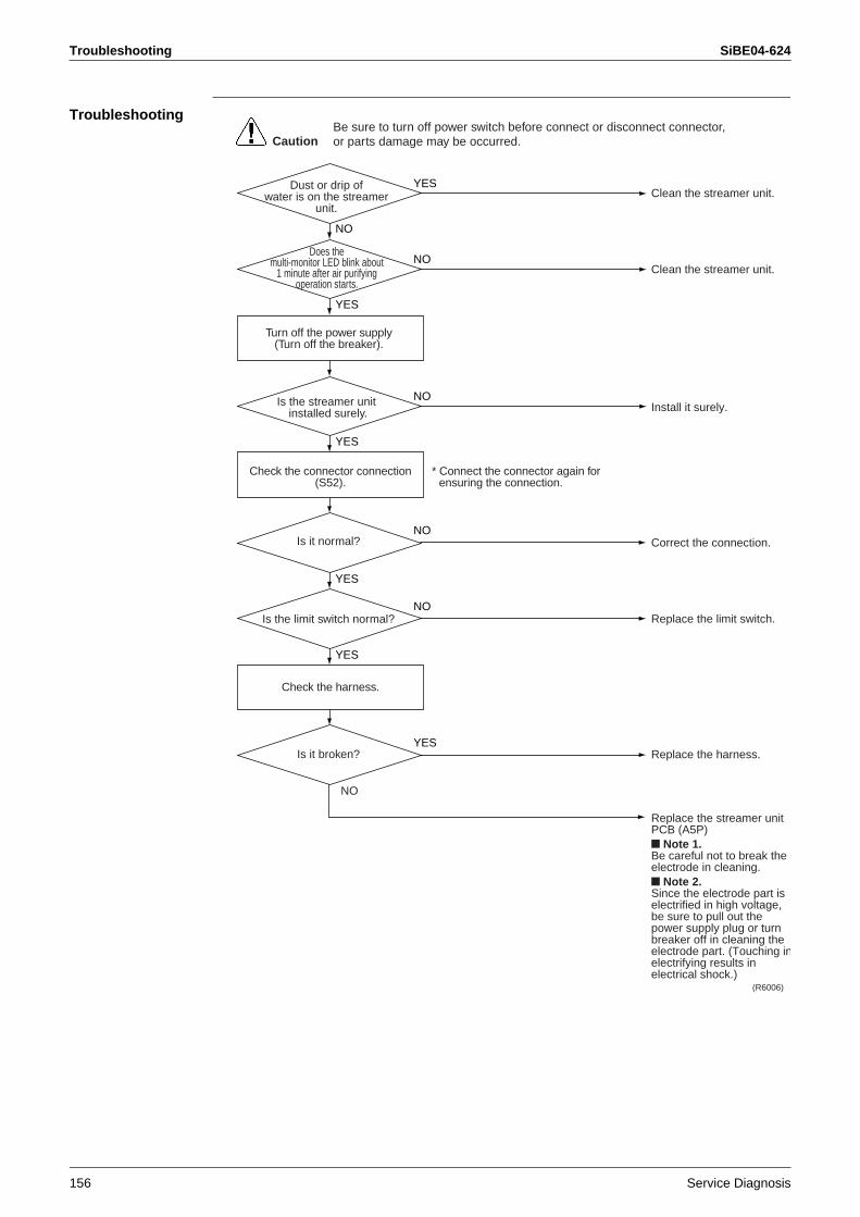
Troubleshooting SiBE04-624
156 Service Diagnosis
Troubleshooting
Clean the streamer unit.
Clean the streamer unit.
Install it surely.
Correct the connection.
Replace the limit switch.
Replace the harness.
Replace the streamer unit PCB (A5P)
Note 1.Be careful not to break the electrode in cleaning.
Note 2.Since the electrode part is electrified in high voltage, be sure to pull out the power supply plug or turn breaker off in cleaning the electrode part. (Touching inelectrifying results in electrical shock.)
(R6006)
CautionBe sure to turn off power switch before connect or disconnect connector, or parts damage may be occurred.
Dust or drip of water is on the streamer
unit.
YES
NO
NO
YES
Does the multi-monitor LED blink about
1 minute after air purifying operation starts.
NO
YES
Is the streamer unit installed surely.
NO
YES
Turn off the power supply (Turn off the breaker).
Check the connector connection (S52).
* Connect the connector again for ensuring the connection.
Check the harness.
Is it normal?
NO
YES
Is the limit switch normal?
YESIs it broken?
NO
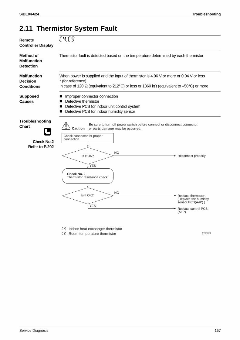
SiBE04-624 Troubleshooting
Service Diagnosis 157
2.11 Thermistor System Fault
Remote Controller Display
C4, C9
Method of Malfunction Detection
Thermistor fault is detected based on the temperature determined by each thermistor
Malfunction Decision Conditions
When power is supplied and the input of thermistor is 4.96 V or more or 0.04 V or less* (for reference)In case of 120 Ω (equivalent to 212°C) or less or 1860 kΩ (equivalent to –50°C) or more
Supposed Causes
Improper connector connectionDefective thermistorDefective PCB for indoor unit control systemDefective PCB for indoor humidity sensor
Troubleshooting Chart
Check No.2Refer to P.202
Reconnect properly.
Replace thermistor.(Replace the humidity sensor PCB(A4P).)
Replace control PCB (A1P).
Is it OK?
(R6005)
CautionBe sure to turn off power switch before connect or disconnect connector, or parts damage may be occurred.
Check connector for proper connection
Is it OK?
NO
NO
YES
YES
Check No. 2Thermistor resistance check
C4 : Indoor heat exchanger thermistorC9 : Room temperature thermistor
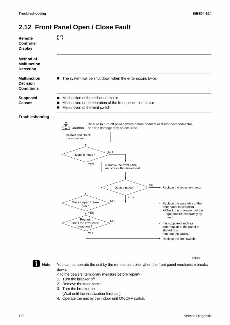
Troubleshooting SiBE04-624
158 Service Diagnosis
2.12 Front Panel Open / Close Fault
Remote Controller Display
C7
Method of Malfunction Detection
Malfunction Decision Conditions
The system will be shut down when the error occurs twice.
SupposedCauses
Malfunction of the reduction motorMalfunction or deterioration of the front panel mechanismMalfunction of the limit switch
Troubleshooting
Note: You cannot operate the unit by the remote controller when the front panel mechanism breaks down.<To the dealers: temporary measure before repair>1. Turn the breaker off.2. Remove the front panel.3. Turn the breaker on.
(Wait until the initialization finishes.)4. Operate the unit by the indoor unit ON/OFF switch.
Restart and checkthe movement.
YES
YES
YES
YES
Remove the front paneland check the movement.
Does it move?
Does it open / closefully?
Restart.Does the error code
reappear?
Does it move?
NO
NO
NO
NO
Replace the reduction motor.
Replace the assembly of the front panel mechanism.
Check the movement of the right and left separately by hand.
It is supposed such as deformation of the panel or stuffed dust.Find out the cause.
Replace the limit switch.
(R3313)
CautionBe sure to turn off power switch before connect or disconnect connector, or parts damage may be occurred.
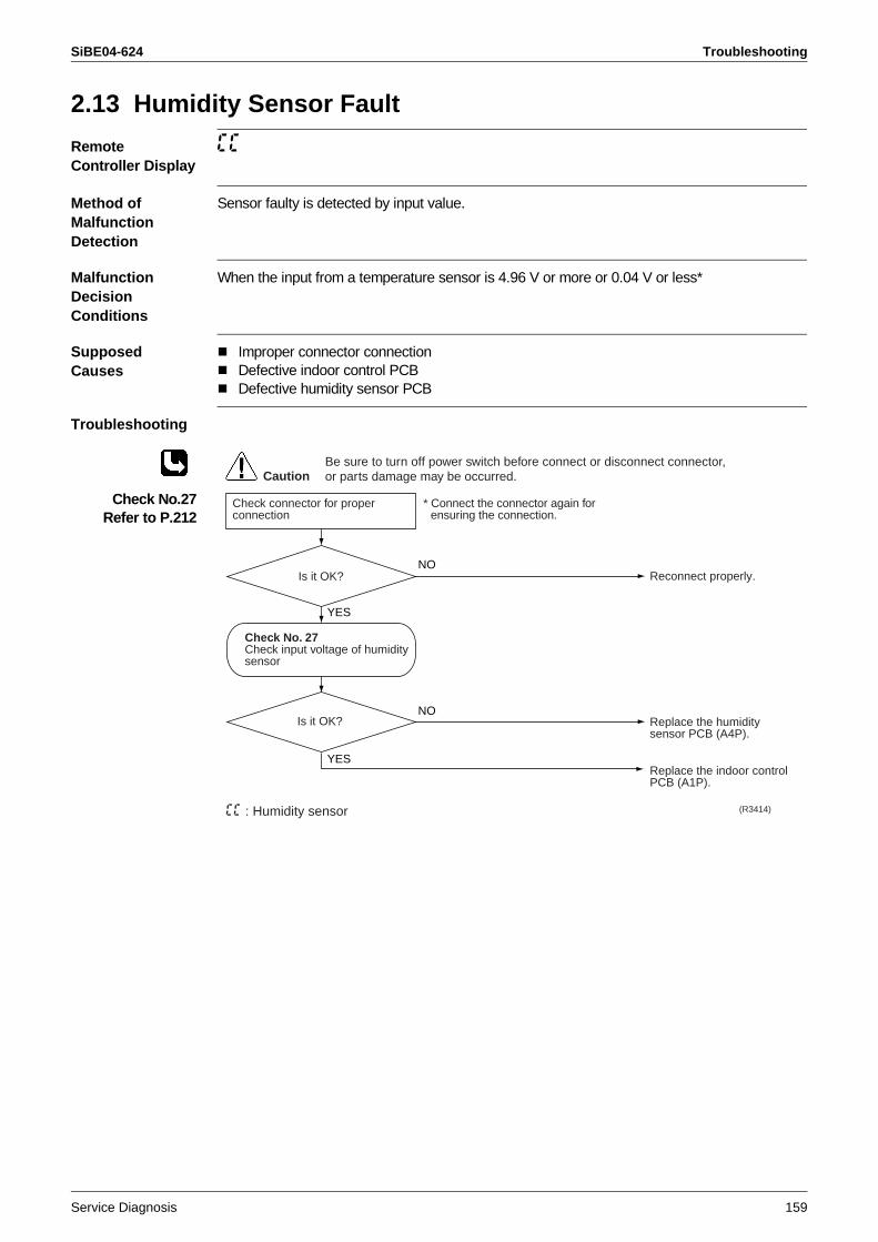
SiBE04-624 Troubleshooting
Service Diagnosis 159
2.13 Humidity Sensor Fault
Remote Controller Display
CC
Method of Malfunction Detection
Sensor faulty is detected by input value.
Malfunction Decision Conditions
When the input from a temperature sensor is 4.96 V or more or 0.04 V or less*
Supposed Causes
Improper connector connectionDefective indoor control PCBDefective humidity sensor PCB
Troubleshooting
Check No.27Refer to P.212
Reconnect properly.
Replace the humidity sensor PCB (A4P).
Replace the indoor control PCB (A1P).
Is it OK?
(R3414)
CautionBe sure to turn off power switch before connect or disconnect connector, or parts damage may be occurred.
Check connector for proper connection
Is it OK?
NO
NO
YES
YES
Check No. 27Check input voltage of humidity sensor
CC : Humidity sensor
* Connect the connector again for ensuring the connection.
Troubleshooting SiBE04-624
160 Service Diagnosis
2.14 Signal Transmission Error (Indoor Unit - Outdoor Unit)
Remote Controller Display
U4
Method of Malfunction Detection
The data sent from the outdoor unit is checked for problem.
Malfunction Decision Conditions
When the data sent from the outdoor unit can not be received without error, or when the disable status of signal transmission continues for 15 sec. and the same status continuously repeats 3 times.
Supposed Causes
Defective outdoor unit PCB Defective indoor unit PCBSignal transmission error between indoor and outdoor unit due to improper wiringSignal transmission error between indoor and outdoor unit due to breakage of relay wire (transmission wire)
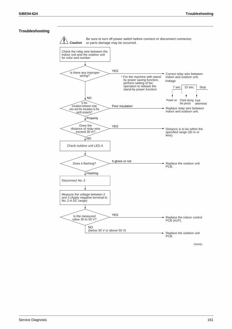
SiBE04-624 Troubleshooting
Service Diagnosis 161
Troubleshooting
NO
Correct relay wire between indoor and outdoor unit.
Replace relay wire between indoor and outdoor unit.
Distance is to be within the specified range (30 m or less).
Replace the outdoor unit PCB.
Replace the indoor control PCB (A1P).
Replace the outdoor unit PCB.
Does thedistance of relay wire
exceed 30 m?
(R6006)
YES
CautionBe sure to turn off power switch before connect or disconnect connector, or parts damage may be occurred.
Check the relay wire between the indoor unit and the outdoor unit for color and number
Check outdoor unit LED A
Is there any improperwiring?
YES
Poor insulationIs the
insulation between relaywire and the insulation to the
earth properly?
Properly
Is the measured value 30 to 50 V?
NO(below 30 V or above 50 V)
YES
NO
Does it flashing?It glows or not
Disconnect No. 3
Flashing
Measure the voltage between 2 and 3 (Apply negative terminal to No. 2 in DC range)
* For the machine with stand-by power saving function, perform setting of fan operation to release the stand-by power function.
Voltage 7 sec.
Faultdetermined
Power on Check duringthis period
15 sec. Stop
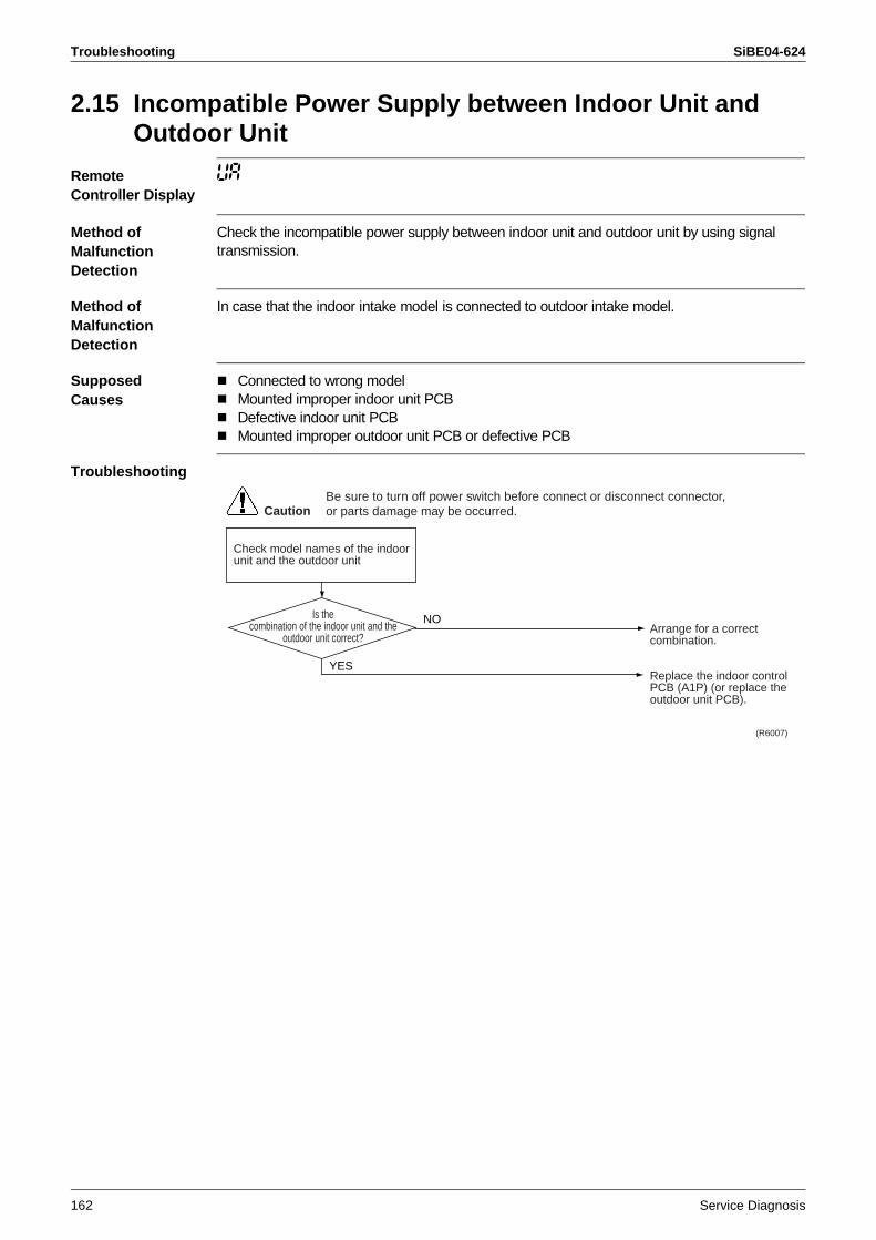
Troubleshooting SiBE04-624
162 Service Diagnosis
2.15 Incompatible Power Supply between Indoor Unit and Outdoor Unit
Remote Controller Display
UA
Method of Malfunction Detection
Check the incompatible power supply between indoor unit and outdoor unit by using signal transmission.
Method of Malfunction Detection
In case that the indoor intake model is connected to outdoor intake model.
Supposed Causes
Connected to wrong modelMounted improper indoor unit PCBDefective indoor unit PCBMounted improper outdoor unit PCB or defective PCB
Troubleshooting
Arrange for a correct combination.
Replace the indoor control PCB (A1P) (or replace the outdoor unit PCB).
(R6007)
CautionBe sure to turn off power switch before connect or disconnect connector, or parts damage may be occurred.
Check model names of the indoor unit and the outdoor unit
Is thecombination of the indoor unit and the
outdoor unit correct?
YES
NO
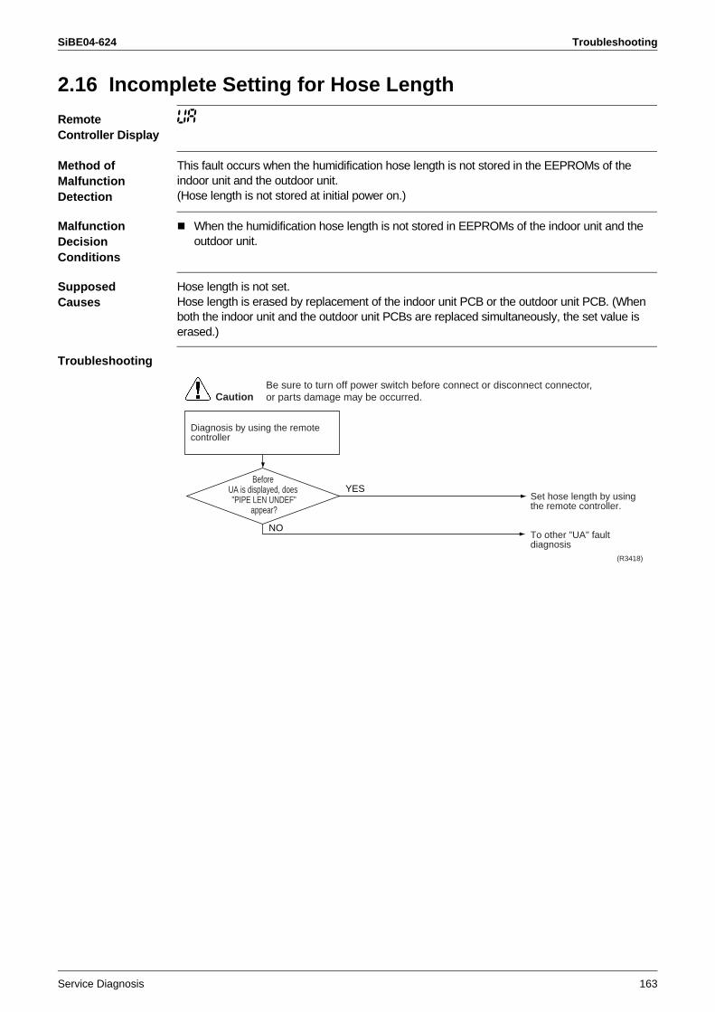
SiBE04-624 Troubleshooting
Service Diagnosis 163
2.16 Incomplete Setting for Hose Length
Remote Controller Display
UA
Method of Malfunction Detection
This fault occurs when the humidification hose length is not stored in the EEPROMs of the indoor unit and the outdoor unit.(Hose length is not stored at initial power on.)
Malfunction Decision Conditions
When the humidification hose length is not stored in EEPROMs of the indoor unit and the outdoor unit.
Supposed Causes
Hose length is not set.Hose length is erased by replacement of the indoor unit PCB or the outdoor unit PCB. (When both the indoor unit and the outdoor unit PCBs are replaced simultaneously, the set value is erased.)
Troubleshooting
Set hose length by using the remote controller.
To other "UA" fault diagnosis
(R3418)
CautionBe sure to turn off power switch before connect or disconnect connector, or parts damage may be occurred.
Diagnosis by using the remote controller
Before UA is displayed, does "PIPE LEN UNDEF"
appear?
NO
YES
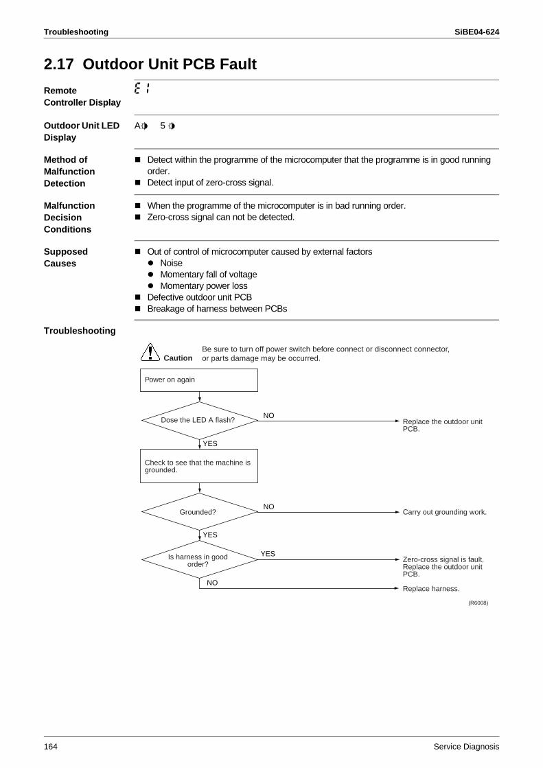
Troubleshooting SiBE04-624
164 Service Diagnosis
2.17 Outdoor Unit PCB Fault
Remote Controller Display
E1
Outdoor Unit LED Display
A5 5 5
Method of Malfunction Detection
Detect within the programme of the microcomputer that the programme is in good running order.Detect input of zero-cross signal.
Malfunction Decision Conditions
When the programme of the microcomputer is in bad running order.Zero-cross signal can not be detected.
Supposed Causes
Out of control of microcomputer caused by external factors NoiseMomentary fall of voltageMomentary power loss
Defective outdoor unit PCBBreakage of harness between PCBs
Troubleshooting
Replace the outdoor unit PCB.
Carry out grounding work.
Zero-cross signal is fault.Replace the outdoor unit PCB.
Replace harness.
(R6008)
CautionBe sure to turn off power switch before connect or disconnect connector, or parts damage may be occurred.
Power on again
NODose the LED A flash?
YES
Is harness in good order?
NO
YES
Check to see that the machine is grounded.
NOGrounded?
YES
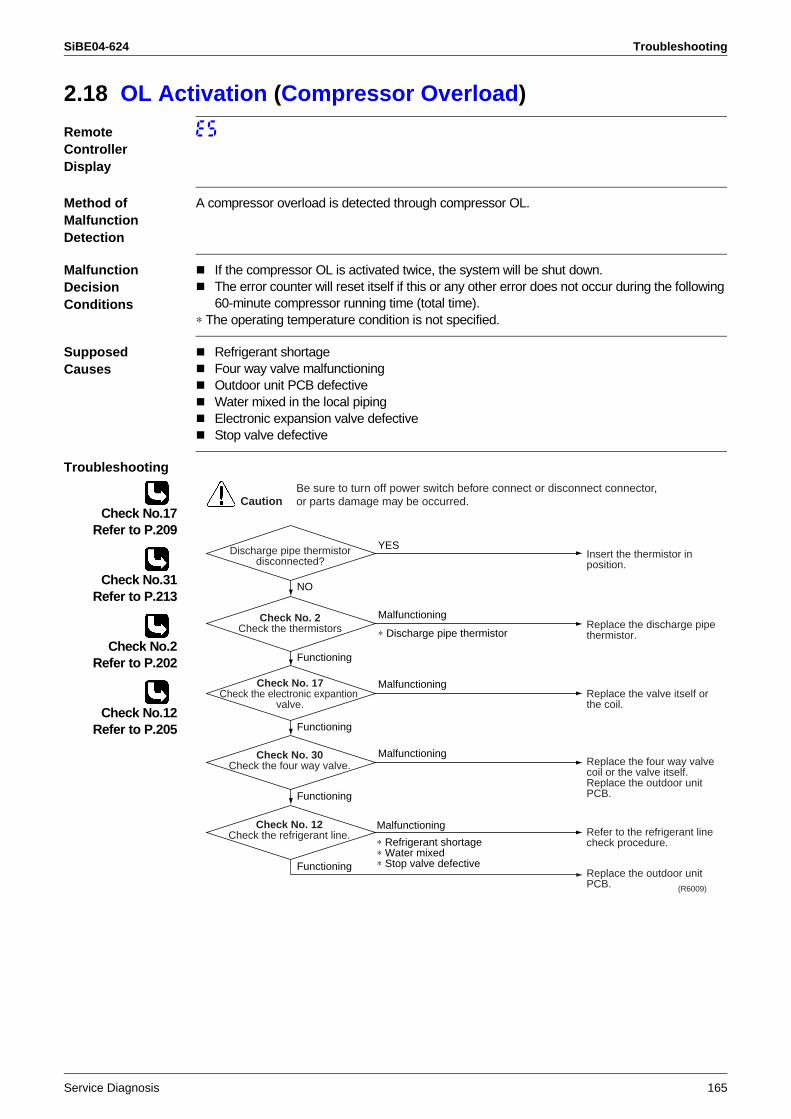
SiBE04-624 Troubleshooting
Service Diagnosis 165
2.18 OL Activation (Compressor Overload)
Remote Controller Display
E5
Method of Malfunction Detection
A compressor overload is detected through compressor OL.
Malfunction Decision Conditions
If the compressor OL is activated twice, the system will be shut down.The error counter will reset itself if this or any other error does not occur during the following 60-minute compressor running time (total time).
∗ The operating temperature condition is not specified.
Supposed Causes
Refrigerant shortageFour way valve malfunctioningOutdoor unit PCB defectiveWater mixed in the local pipingElectronic expansion valve defectiveStop valve defective
Troubleshooting
Check No.17Refer to P.209
Check No.31Refer to P.213
Check No.2Refer to P.202
Check No.12Refer to P.205
Insert the thermistor in position.
Replace the discharge pipe thermistor.
Replace the valve itself or the coil.
Replace the four way valve coil or the valve itself.Replace the outdoor unit PCB.
Refer to the refrigerant line check procedure.
Replace the outdoor unit PCB. (R6009)
CautionBe sure to turn off power switch before connect or disconnect connector, or parts damage may be occurred.
Discharge pipe thermistor disconnected?
YES
Malfunctioning
∗ Discharge pipe thermistor
NO
Functioning
Functioning
Check No. 12Check the refrigerant line.
Malfunctioning
∗ Refrigerant shortage∗ Water mixed∗ Stop valve defective
Check No. 2Check the thermistors
Malfunctioning
Functioning
Check No. 17Check the electronic expantion
valve.
Malfunctioning
Functioning
Check No. 30Check the four way valve.
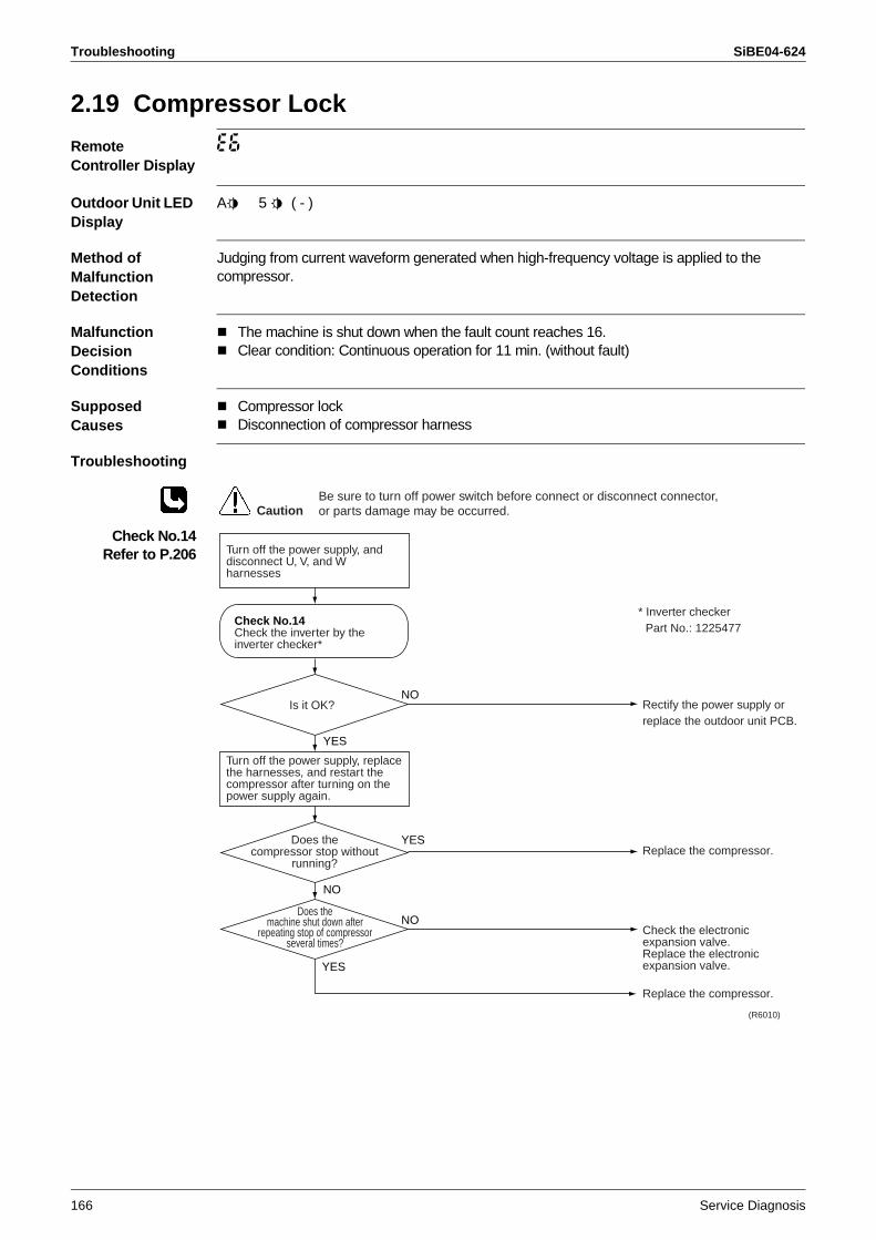
Troubleshooting SiBE04-624
166 Service Diagnosis
2.19 Compressor Lock
Remote Controller Display
E6
Outdoor Unit LED Display
A5 5 5 ( - )
Method of Malfunction Detection
Judging from current waveform generated when high-frequency voltage is applied to the compressor.
Malfunction Decision Conditions
The machine is shut down when the fault count reaches 16.Clear condition: Continuous operation for 11 min. (without fault)
Supposed Causes
Compressor lockDisconnection of compressor harness
Troubleshooting
Check No.14Refer to P.206
* Inverter checkerPart No.: 1225477
Rectify the power supply orreplace the outdoor unit PCB.
Replace the compressor.
Check the electronic expansion valve.Replace the electronic expansion valve.
Replace the compressor.
(R6010)
CautionBe sure to turn off power switch before connect or disconnect connector, or parts damage may be occurred.
Turn off the power supply, and disconnect U, V, and W harnesses
Does themachine shut down after
repeating stop of compressorseveral times?
YES
NO
YES
YES
NO
NOIs it OK?
Does thecompressor stop without
running?
Turn off the power supply, replace the harnesses, and restart the compressor after turning on the power supply again.
Check No.14Check the inverter by the inverter checker*
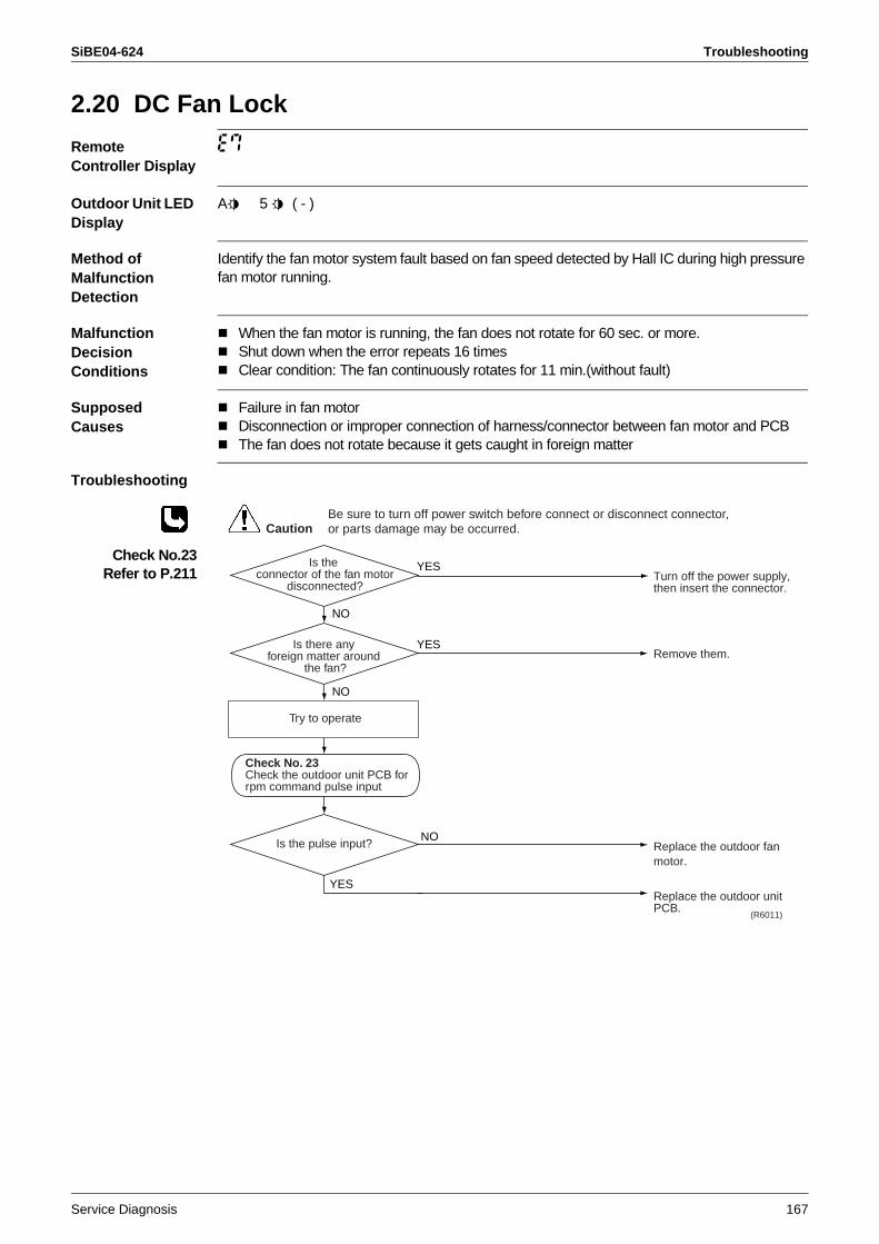
SiBE04-624 Troubleshooting
Service Diagnosis 167
2.20 DC Fan Lock
Remote Controller Display
E7
Outdoor Unit LED Display
A5 5 5 ( - )
Method of Malfunction Detection
Identify the fan motor system fault based on fan speed detected by Hall IC during high pressure fan motor running.
Malfunction Decision Conditions
When the fan motor is running, the fan does not rotate for 60 sec. or more.Shut down when the error repeats 16 timesClear condition: The fan continuously rotates for 11 min.(without fault)
Supposed Causes
Failure in fan motorDisconnection or improper connection of harness/connector between fan motor and PCBThe fan does not rotate because it gets caught in foreign matter
Troubleshooting
Check No.23Refer to P.211 Turn off the power supply,
then insert the connector.
Remove them.
Replace the outdoor fan motor.
Replace the outdoor unit PCB.
(R6011)
Is the connector of the fan motor
disconnected?
Is there any foreign matter around
the fan?
Check No. 23Check the outdoor unit PCB for rpm command pulse input
Is the pulse input?
Try to operate
CautionBe sure to turn off power switch before connect or disconnect connector, or parts damage may be occurred.
YES
NO
YES
YES
NO
NO
Troubleshooting SiBE04-624
168 Service Diagnosis
2.21 Input Over Current Detection
Remote Controller Display
E8
Outdoor Unit LED Display
A5 5 5 ( - )
Method of Malfunction Detection
Detect an input overcurrent by checking the inverter power consumption or the input current detected by CT with the compressor running.
Malfunction Decision Conditions
When 14 A or more of inverter power consumption or CT input continues for 5 sec.The compressor stops if the error occurs, and restarts automatically after 3 minutes standby.
Supposed Causes
Overcurrent due to defective compressorOvercurrent due to defective power transistorOvercurrent due to defective electrolytic capacitor of inverter main circuitOvercurrent due to defective outdoor unit PCBDetection error due to defective outdoor unit PCBOvercurrent due to short circuit
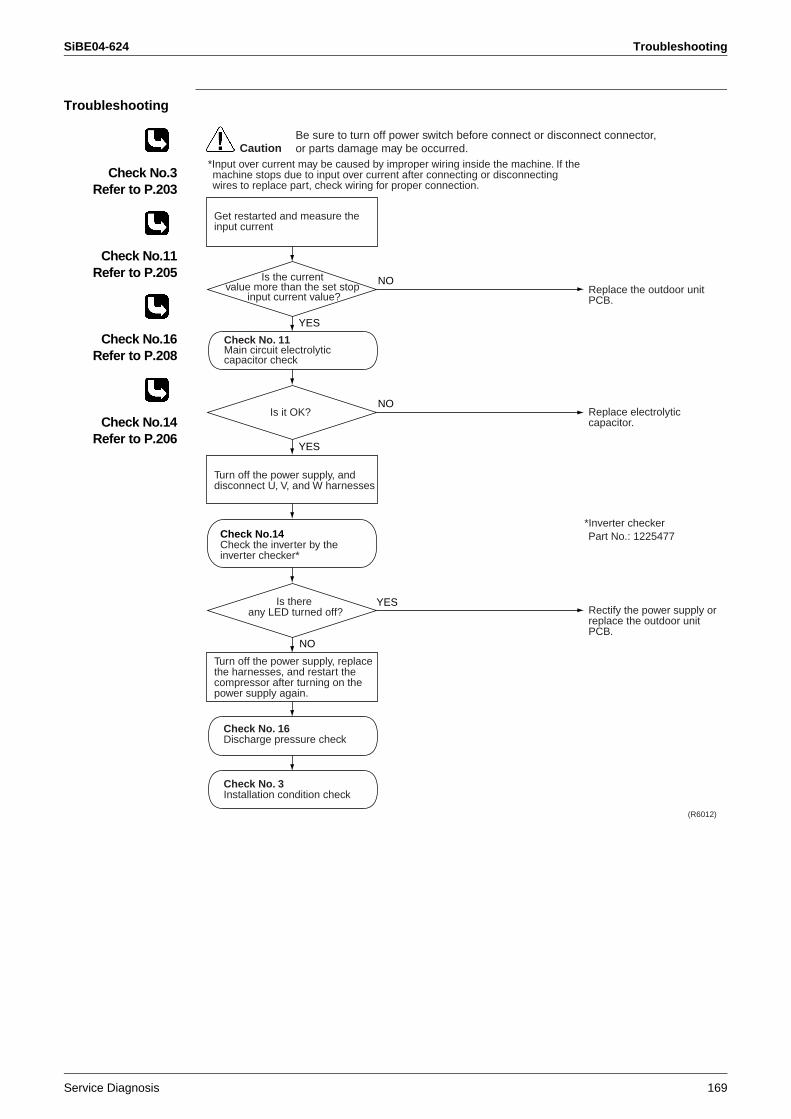
SiBE04-624 Troubleshooting
Service Diagnosis 169
Troubleshooting
Check No.3Refer to P.203
Check No.11Refer to P.205
Check No.16Refer to P.208
Check No.14Refer to P.206
Check No.14Check the inverter by the inverter checker*
Replace the outdoor unit PCB.
Replace electrolytic capacitor.
Rectify the power supply orreplace the outdoor unit PCB.
(R6012)
Get restarted and measure the input current
Is the current value more than the set stop
input current value?
Turn off the power supply, and disconnect U, V, and W harnesses
Is there any LED turned off?
Check No. 16Discharge pressure check
Check No. 3Installation condition check
Turn off the power supply, replace the harnesses, and restart the compressor after turning on the power supply again.
Check No. 11Main circuit electrolytic capacitor check
Is it OK?
CautionBe sure to turn off power switch before connect or disconnect connector, or parts damage may be occurred.
YES
YES
YES
NO
NO
NO
*Input over current may be caused by improper wiring inside the machine. If the machine stops due to input over current after connecting or disconnecting wires to replace part, check wiring for proper connection.
*Inverter checkerPart No.: 1225477
Troubleshooting SiBE04-624
170 Service Diagnosis
2.22 Four Way Valve Fault
Remote Controller Display
EA
Outdoor Unit LED Display
A5 5 5 ( - )
Method of Malfunction Detection
The room temperature thermistor, the indoor heat exchanger thermistor, the outdoor air thermistor, and the outdoor heat exchanger thermistor are checked to see if they function within their normal ranges in the operating mode.
Malfunction Decision Conditions
When one of the follow condition continues for 10 min, the compressor stops, and restarts automatically after 3 minutes standby.
Cooling / drying(Room temperature – temperature of indoor heat exchanger) < – 5°CHeating(Temperature of indoor heat exchanger – room temperature ) < – 5°C
Shut down when the error repeats twiceClear condition : Continuous operation for 60 minutes.
Supposed Causes
Improper connector connectionDefective thermistorDefective outdoor unit PCBDefective coil or harness of 4-way valve Defective 4-way valveInsufficient gasForeign substance mixed in refrigerant
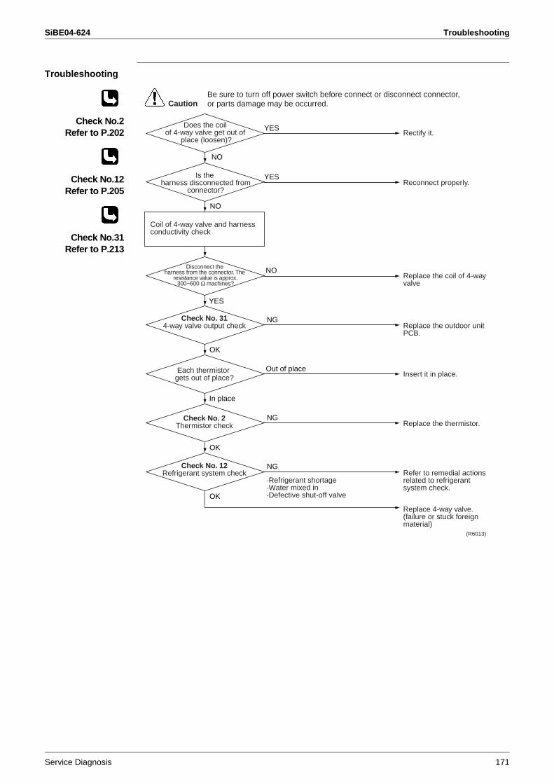
SiBE04-624 Troubleshooting
Service Diagnosis 171
Troubleshooting
Check No.2Refer to P.202
Check No.12Refer to P.205
Check No.31Refer to P.213
Rectify it.
Reconnect properly.
Replace the coil of 4-way valve
Replace the outdoor unit PCB.
Insert it in place.
Replace the thermistor.
Refer to remedial actions related to refrigerant system check.
Replace 4-way valve.(failure or stuck foreign material)
(R6013)
Does the coil of 4-way valve get out of
place (loosen)?
Is the harness disconnected from
connector?
Check No. 314-way valve output check
Each thermistor gets out of place?
Check No. 2Thermistor check
Check No. 12Refrigerant system check
Coil of 4-way valve and harness conductivity check
Disconnect the harness from the connector. The
resistance value is approx.300~600 Ω machines?
CautionBe sure to turn off power switch before connect or disconnect connector, or parts damage may be occurred.
NO
NO
NO
NG
NG
Out of place
In place
OK
OK
NG
OK
YES
YES
YES
·Refrigerant shortage·Water mixed in·Defective shut-off valve
Troubleshooting SiBE04-624
172 Service Diagnosis
2.23 Discharge Pipe Temperature Control
Remote Controller Display
F3
Outdoor Unit LED Display
A5 55 ( - )
Method of Malfunction Detection
Discharge pipe temperature control (stop, frequency attenuation, etc.) is executed based on the temperature detected by the discharge pipe thermistor.
Malfunction Decision Conditions
The compressor stops when the discharge pipe temperature is 118°C or more. (Fault condition is cleared when the discharge pipe temperature is below 85°C)Shut down when the error repeats 4 timesClear condition : Continuous operation for 60 minutes
Supposed Causes
Insufficient gasFaulty operation of 4-way valveDefective discharge pipe thermistor(Defective heat exchanger thermistor or outdoor air thermistor)Defective outdoor unit PCBWater mixed in the field pipingDefective electronic expansion valveDefective stop valveDefective indoor solenoid valve
Troubleshooting
Check No.2Refer to P.202
Check No.12Refer to P.205
Check No.17Refer to P.209
Replace the thermistor.
Replace main body or coil of electronic expansion valve.
Refer to remedial actions related to refrigerantsystem check.
Replace the outdoor unit PCB.
(R3431)
Check No. 2Thermistor check
Check No. 17Electronic expansion valve
check
Check No. 12Refrigerant system check
CautionBe sure to turn off power switch before connect or disconnect connector, or parts damage may be occurred.
NG
OK
NG
OK
NG
OK
·Discharge pipe thermistor·Outdoor heat exchanger thermistor·Outdoor air thermistor
·Insufficient gas·Faulty operation of 4-way valve·Water mixed in·Defective stop valve
SiBE04-624 Troubleshooting
Service Diagnosis 173
2.24 High Pressure Control in Cooling
Remote Controller Display
F6
Outdoor Unit LED Display
A5 55 ( - )
Method of Malfunction Detection
During cooling, high pressure control (stop, frequency attenuation, etc.) is executed according to the temperature detected by the heat exchanger thermistor.
Malfunction Decision Conditions
During cooling, when the temperature detected by the heat exchanger thermistor is 63°C or more. (Fault condition is cleared when the temperature is below 52°C.)
Supposed Causes
Insufficient installation spaceDefective outdoor fanDefective electronic expansion valveDefective heat exchanger thermistorDefective outdoor unit PCB Defective stop valveDefective solenoid valve for dehumidification
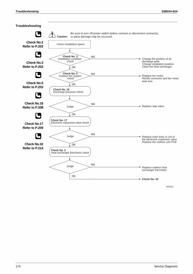
Troubleshooting SiBE04-624
174 Service Diagnosis
Troubleshooting
Check No.2Refer to P.202
Check No.3Refer to P.203
Check No.5Refer to P.203
Check No.16Refer to P.208
Check No.17Refer to P.209
Check No.32Refer to P.214
Change the position of air discharge grille.Change installation position.Clean the heat exchanger.
Replace fan motor.Rectify connector and fan motor lead wire.
Replace stop valve.
Replace main body or coil of the electronic expansion valve.Replace the outdoor unit PCB.
Replace outdoor heat exchanger thermistor.
Check No. 32
(R3433)
Check installation space
Check No. 3Installation condition
check
Check No. 5Outdoor fan system
check
Check No. 17Electronic expansion valve check
Check No. 2Heat exchanger thermistor check
Judge
Judge
Judge
Check No. 16Discharge pressure check
OK
NG
OK
NG
OK
NG
OK
NG
OK
NG
Be sure to turn off power switch before connect or disconnect connector, or parts damage may be occurred.Caution
SiBE04-624 Troubleshooting
Service Diagnosis 175
2.25 Compressor Sensor System Fault
Remote Controller Display
H0
Outdoor Unit LED Display
A5 55 ( - )
Method of Malfunction Detection
Fault condition is identified by DC current which is detected before compressor startup.
Malfunction Decision Conditions
When the DC current before compressor startup is other than 0.5 to 4.5 V (detected by converting the sensor output to voltage), or the DC voltage is 50 V or less.
Supposed Causes
Defective PCBHarness disconnection / defective connection
Troubleshooting
Replace the outdoor unit PCB.
CautionBe sure to turn off power switch before connect or disconnect connector, or parts damage may be occurred.
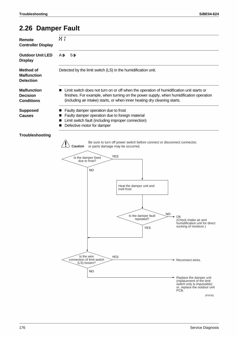
Troubleshooting SiBE04-624
176 Service Diagnosis
2.26 Damper Fault
Remote Controller Display
H1
Outdoor Unit LED Display
A5 55
Method of Malfunction Detection
Detected by the limit switch (LS) in the humidification unit.
Malfunction Decision Conditions
Limit switch does not turn on or off when the operation of humidification unit starts or finishes. For example, when turning on the power supply, when humidification operation (including air intake) starts, or when inner heating dry cleaning starts.
Supposed Causes
Faulty damper operation due to frost Faulty damper operation due to foreign materialLimit switch fault (including improper connection)Defective motor for damper
Troubleshooting
OK (Check intake air and humidification unit for direct sucking of moisture.)
Reconnect wires.
Replace the damper unit(replacement of the limit switch only is impossible) or, replace the outdoor unit PCB.
Is the damper fixeddue to frost?
(R3435)
CautionBe sure to turn off power switch before connect or disconnect connector, or parts damage may be occurred.
Heat the damper unit andmelt frost
Is the damper faultrepeated?
NO
YES
YES
Is the wireconnection of limit switch
(LS) loosen?
NO
NO
YES
SiBE04-624 Troubleshooting
Service Diagnosis 177
2.27 Position Sensor Fault
Remote Controller Display
H6
Outdoor Unit LED Display
A5 55 ( - )
Method of Malfunction Detection
Startup failure of the compressor is identified by rpm information of the compressor and by electric component position detector.
Malfunction Decision Conditions
When the compressor does not run for 15 sec. after receiving operation start commandThe machine shuts down if the fault occurs 16 times Clear condition: The compressor continuously runs for 10 min. without fault
Supposed Causes
Detection error due to disconnection of compressor harnessStartup failure due to defective compressorStartup failure due to defective outdoor unit PCBStartup failure due to closed stop valveInput voltage fault
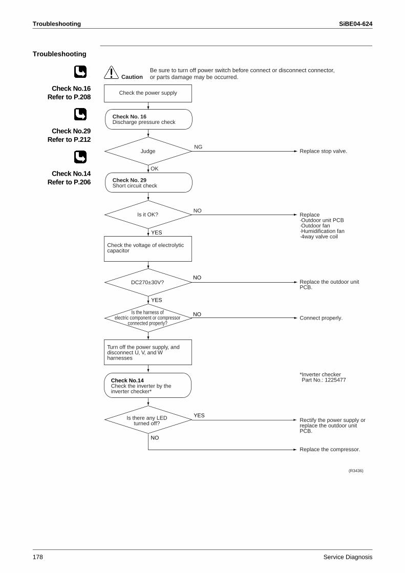
Troubleshooting SiBE04-624
178 Service Diagnosis
Troubleshooting
Check No.16Refer to P.208
Check No.29Refer to P.212
Check No.14Refer to P.206
YES
YES
Replace stop valve.
Replace·Outdoor unit PCB·Outdoor fan·Humidification fan·4way valve coil
Replace the outdoor unit PCB.
Connect properly.
*Inverter checkerPart No.: 1225477
Rectify the power supply orreplace the outdoor unit PCB.
Replace the compressor.
Judge
Is there any LED turned off?
(R3436)
Check No. 16Discharge pressure check
NO
CautionBe sure to turn off power switch before connect or disconnect connector, or parts damage may be occurred.
Is it OK?
Check the voltage of electrolytic capacitor
DC270±30V?NO
Check No. 29Short circuit check
Is the harness ofelectric component or compressor
connected properly?
NO
Turn off the power supply, and disconnect U, V, and W harnesses
Check the power supply
NG
OK
NO
YES
Check No.14Check the inverter by the inverter checker*
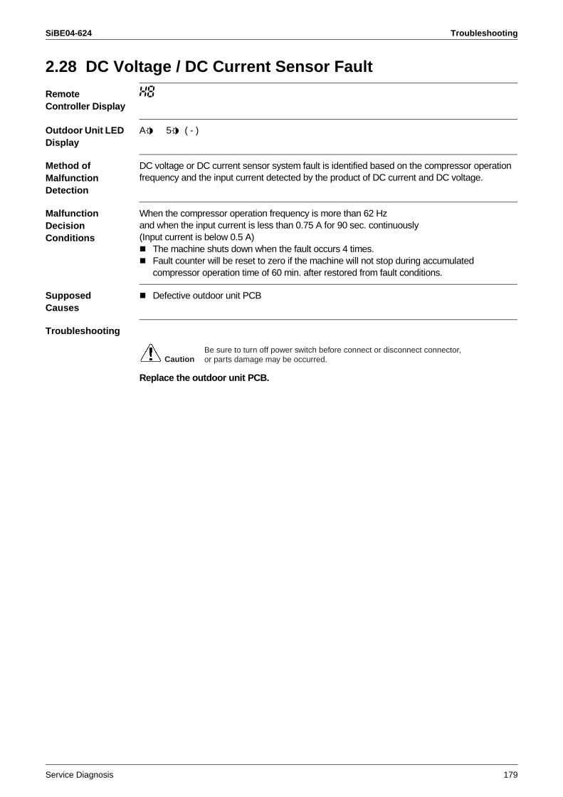
SiBE04-624 Troubleshooting
Service Diagnosis 179
2.28 DC Voltage / DC Current Sensor Fault
Remote Controller Display
H8
Outdoor Unit LED Display
A5 55 ( - )
Method of Malfunction Detection
DC voltage or DC current sensor system fault is identified based on the compressor operation frequency and the input current detected by the product of DC current and DC voltage.
Malfunction Decision Conditions
When the compressor operation frequency is more than 62 Hzand when the input current is less than 0.75 A for 90 sec. continuously(Input current is below 0.5 A)
The machine shuts down when the fault occurs 4 times.Fault counter will be reset to zero if the machine will not stop during accumulated compressor operation time of 60 min. after restored from fault conditions.
Supposed Causes
Defective outdoor unit PCB
Troubleshooting
Replace the outdoor unit PCB.
CautionBe sure to turn off power switch before connect or disconnect connector, or parts damage may be occurred.
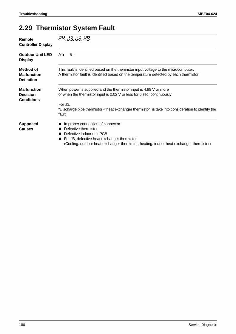
Troubleshooting SiBE04-624
180 Service Diagnosis
2.29 Thermistor System Fault
Remote Controller Display
P4, J3, J6, H9
Outdoor Unit LED Display
A5 5 -
Method of Malfunction Detection
This fault is identified based on the thermistor input voltage to the microcomputer.A thermistor fault is identified based on the temperature detected by each thermistor.
Malfunction Decision Conditions
When power is supplied and the thermistor input is 4.98 V or moreor when the thermistor input is 0.02 V or less for 5 sec. continuously
For J3,“Discharge pipe thermistor < heat exchanger thermistor” is take into consideration to identify the fault.
Supposed Causes
Improper connection of connectorDefective thermistorDefective indoor unit PCBFor J3, defective heat exchanger thermistor (Cooling: outdoor heat exchanger thermistor, heating: indoor heat exchanger thermistor)
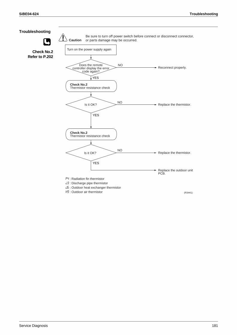
SiBE04-624 Troubleshooting
Service Diagnosis 181
Troubleshooting
Check No.2Refer to P.202
YES
Reconnect properly.
Replace the thermistor.
Replace the thermistor.
Replace the outdoor unit PCB.
Does the remotecontroller display the error
code again?
Is it OK?
(R3441)
CautionBe sure to turn off power switch before connect or disconnect connector, or parts damage may be occurred.
Is it OK?
Check No.2Thermistor resistance check
Check No.2Thermistor resistance check
Turn on the power supply again
NO
YES
NO
YES
NO
P4 : Radiation fin thermistorJ3 : Discharge pipe thermistorJ6 : Outdoor heat exchanger thermistorH9 : Outdoor air thermistor
Troubleshooting SiBE04-624
182 Service Diagnosis
2.30 Abnormal Temperature in Electrical Box
Remote Controller Display
L3
Outdoor Unit LED Display
A5 5 -
Method of Malfunction Detection
Temperature rise in the electrical box is identified based on the temperature of the radiation fin detected by the fin thermistor with the compressor off.
Malfunction Decision Conditions
When the temperature of the radiation fin is 122°C or more during the compressor off. (When the temperature drops below 113°C, fault condition is cleared.)
Supposed Causes
Fin temperature rise due to defective outdoor fanFin temperature rise due to short circuitDetection error due to defective fin thermistorDetection error due to improper connection of connectorDetection error due to defective outdoor unit PCB
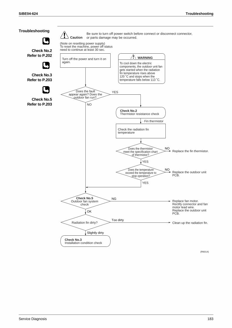
SiBE04-624 Troubleshooting
Service Diagnosis 183
Troubleshooting
Check No.2Refer to P.202
Check No.3Refer to P.203
Check No.5Refer to P.203
Replace the fin thermistor.
Replace the outdoor unit PCB.
Replace fan motor.Rectify connector and fan motor lead wire. Replace the outdoor unit PCB.
Clean up the radiation fin.
Does the faultappear again? Does the
outdoor fan run?
Check No.5Outdoor fan system
check
(R6014)
OK
CautionBe sure to turn off power switch before connect or disconnect connector, or parts damage may be occurred.
Does the thermistormeet the specification chart
of thermistor?
NO
Check No.2Thermistor resistance check
Turn off the power and turn it on again.
YES
NO
NG
Check the radiation fin temperature
Does the temperatureexceed the temperature to
stop operation?
YES
NO
YES
(Note on resetting power supply)To reset the machine, power off status need to continue at least 30 sec.
Radiation fin dirty?
Slightly dirty
Too dirty
Check No.3Installation condition check
To cool down the electric components, the outdoor unit fan gets started when the radiation fin temperature rises above 120 ˚C and stops when the temperature falls below 113 ˚C.
WARNING
· Fin thermistor
Troubleshooting SiBE04-624
184 Service Diagnosis
2.31 Temperature Rise in Radiation Fin
Remote Controller Display
L4
Outdoor Unit LED Display
A5 55
Method of Malfunction Detection
Temperature rise in the radiation fin is identified based on the temperature of the radiation fin detected by the fin thermistor with the compressor on.
Malfunction Decision Conditions
The compressor stops when the radiation fin temperature is 86 °C or more. (Fault condition is cleared when the radiation fin temperature is below 67 °C.)Shut down when the error repeats 255 timesClear condition : Continuous operation for 60 minutes
Supposed Causes
Fin temperature rise due to defective outdoor fanFin temperature rise due to short circuitDetection error due to defective fin thermistorDetection error due to improper connection of connectorDetection error due to defective outdoor unit PCB
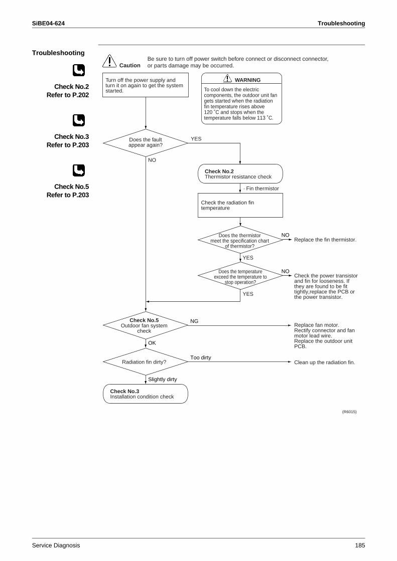
SiBE04-624 Troubleshooting
Service Diagnosis 185
Troubleshooting
Check No.2Refer to P.202
Check No.3Refer to P.203
Check No.5Refer to P.203
Replace the fin thermistor.
Check the power transistor and fin for looseness. If they are found to be fit tightly,replace the PCB or the power transistor.
Replace fan motor.Rectify connector and fan motor lead wire.Replace the outdoor unit PCB.
Clean up the radiation fin.
Does the faultappear again?
Check No.5Outdoor fan system
check
(R6015)
OK
CautionBe sure to turn off power switch before connect or disconnect connector, or parts damage may be occurred.
Does the thermistormeet the specification chart
of thermistor?
NO
Check No.2Thermistor resistance check
Turn off the power supply and turn it on again to get the system started.
YES
NO
NG
Check the radiation fin temperature
Does the temperatureexceed the temperature to
stop operation?
YES
NO
YES
Radiation fin dirty?
Slightly dirty
Too dirty
Check No.3Installation condition check
To cool down the electric components, the outdoor unit fan gets started when the radiation fin temperature rises above 120 ˚C and stops when the temperature falls below 113 ˚C.
WARNING
· Fin thermistor
Troubleshooting SiBE04-624
186 Service Diagnosis
2.32 Output Overcurrent
Remote Controller Display
L5
Outdoor Unit LED Display
A5 55
Method of Malfunction Detection
An output overcurrent is detected by checking the current that flows in the inverter DC section.
Malfunction Decision Conditions
A position signal error occurs while the compressor is running.A speed error occurs while the compressor is running.The machine shuts down when the signal of output overcurrent is sent 8 times from the output overcurrent detection circuit to the microcomputer.Clear condition: The machine continuously runs for about 11 min. (without fault)
Supposed Causes
Overcurrent due to defective power transistorOvercurrent due to wrong internal wiring Overcurrent due to abnormal supply voltageOvercurrent due to defective PCBDetection error due to defective PCBOvercurrent due to closed stop valveOvercurrent due to defective compressorOvercurrent due to poor installation condition Defective indoor solenoid valve
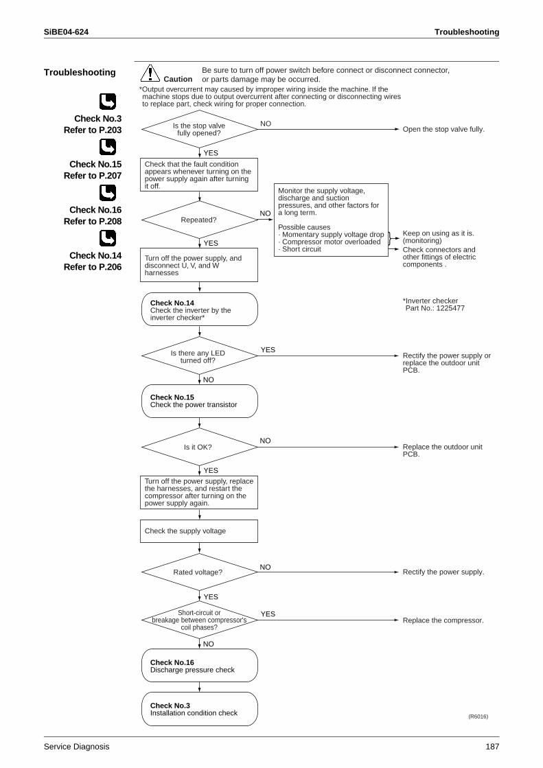
SiBE04-624 Troubleshooting
Service Diagnosis 187
Troubleshooting
Check No.3Refer to P.203
Check No.15Refer to P.207
Check No.16Refer to P.208
Check No.14Refer to P.206
YES
YES
Open the stop valve fully.
Keep on using as it is. (monitoring)Check connectors and other fittings of electric components .
*Inverter checkerPart No.: 1225477
Rectify the power supply orreplace the outdoor unit PCB.
Replace the outdoor unit PCB.
Rectify the power supply.
Replace the compressor.
Is there any LED turned off?
(R6016)
NO
CautionBe sure to turn off power switch before connect or disconnect connector, or parts damage may be occurred.
Is the stop valvefully opened?
Check that the fault condition appears whenever turning on the power supply again after turning it off.
Repeated?NO
YES
NO
YES
NO
Turn off the power supply, and disconnect U, V, and W harnesses
Turn off the power supply, replace the harnesses, and restart the compressor after turning on the power supply again.
Check the supply voltage
NO
YES
*Output overcurrent may caused by improper wiring inside the machine. If the machine stops due to output overcurrent after connecting or disconnecting wires to replace part, check wiring for proper connection.
Check No.15Check the power transistor
Check No.14Check the inverter by the inverter checker*
Check No.16Discharge pressure check
Is it OK?
Rated voltage?
Short-circuit orbreakage between compressor's
coil phases?
NO
YES
Check No.3Installation condition check
Monitor the supply voltage, discharge and suction pressures, and other factors for a long term.
Possible causes· Momentary supply voltage drop· Compressor motor overloaded· Short circuit
Troubleshooting SiBE04-624
188 Service Diagnosis
2.33 Insufficient Gas
Remote Controller Display
U0
Outdoor Unit LED Display
A5 55 ( - )
Method of Malfunction Detection
Gas shortage detection I:Gas shortage is detected by checking the input current value and the compressor running frequency. If the gas is short, the input current is smaller than the normal value.
Gas shortage detection III:Gas shortage is detected by checking the difference between ambient temperature and heat exchanger temperature. If the gas is short, the difference is smaller than the normal value.
Malfunction Decision Conditions
Gas shortage detection I: The following conditions continue for 7 minutes.
Input current × input voltage ≤ 2800 / 256 × output frequency –350 (W)Output frequency > 54 (Hz)
Gas shortage detection III:When the difference of the temperature is smaller than , it is regarded as insufficient gas.
If a gas shortage error takes place 4 times straight, the system will be shut down. The error counter will reset itself if this or any other error does not occur during the following 60-minute compressor running time (total time).
Supposed Causes
Refrigerant shortage (refrigerant leakage)Refrigerant heat exchanger driftPoor compression performance of compressorClosed stop valve Defective electronic expansion valveDefective solenoid valve for dehumidifying
Coolingroom temperature − indoor heat exchanger temperature 4.0°C
outdoor heat exchanger temperature − outdoor temperature 4.0°C
Heatingindoor heat exchanger temperature − room temperature 4.0°C
outdoor temperature − outdoor heat exchanger temperature 4.0°C
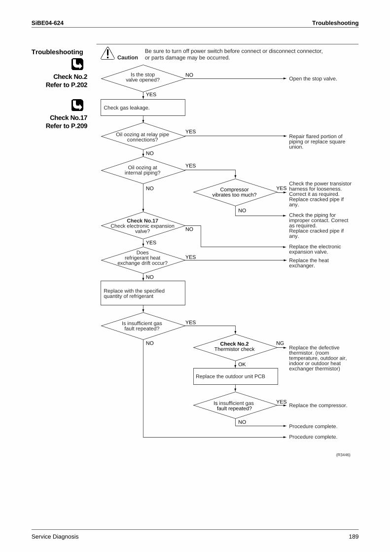
SiBE04-624 Troubleshooting
Service Diagnosis 189
Troubleshooting
Check No.2Refer to P.202
Check No.17Refer to P.209
NO
YES
Open the stop valve.
Repair flared portion of piping or replace square union.
Check the power transistor harness for looseness. Correct it as required.Replace cracked pipe if any.
Check the piping for improper contact. Correct as required.Replace cracked pipe if any.
Replace the electronic expansion valve.
Replace the heat exchanger.
Replace the defective thermistor. (room temperature, outdoor air, indoor or outdoor heat exchanger thermistor)
Replace the compressor.
Procedure complete.
Procedure complete.
(R3446)
CautionBe sure to turn off power switch before connect or disconnect connector, or parts damage may be occurred.
Is the stopvalve opened?
Check gas leakage.
Oil oozing at relay pipe connections?
YES
NO
NO
Oil oozing atinternal piping?
YES
NO
YES
Check No.17Check electronic expansion
valve?
Compressorvibrates too much?
NO
Is insufficient gas fault repeated?
Check No.2Thermistor check
OK
NG
YES
Doesrefrigerant heat
exchange drift occur?
Is insufficient gas fault repeated?
NO
NO
NO
YES
YES
YES
Replace with the specified quantity of refrigerant
Replace the outdoor unit PCB
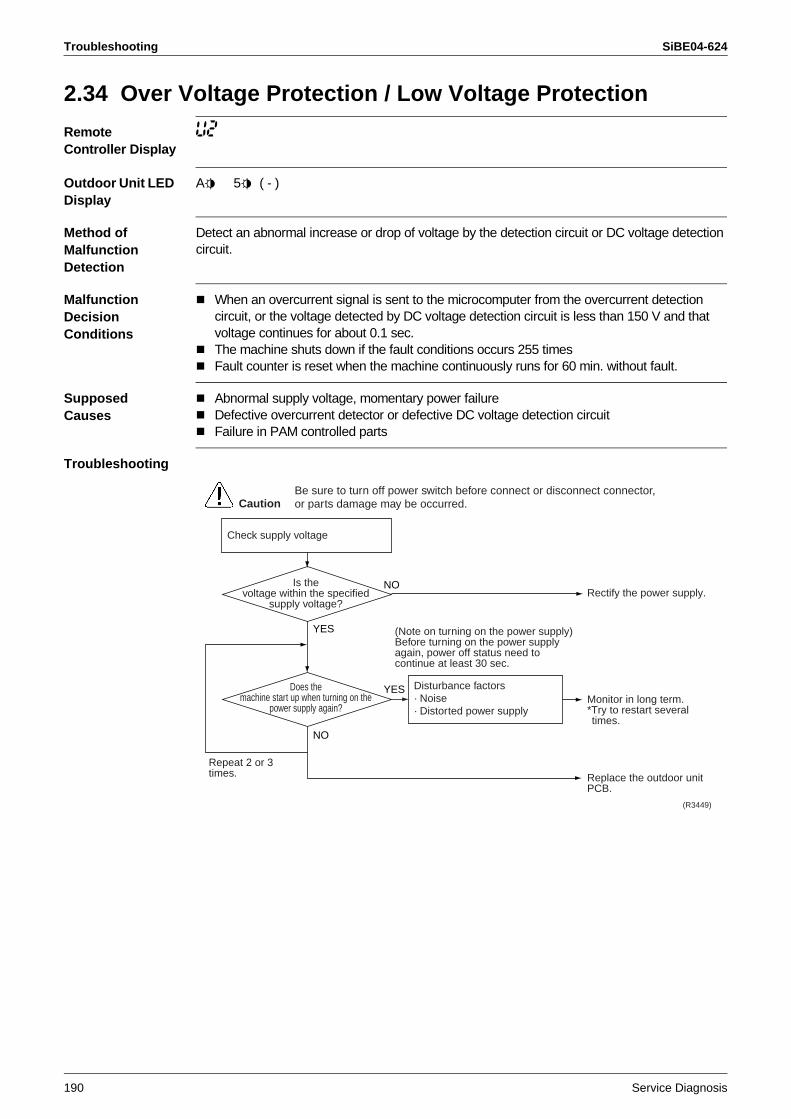
Troubleshooting SiBE04-624
190 Service Diagnosis
2.34 Over Voltage Protection / Low Voltage Protection
Remote Controller Display
U2
Outdoor Unit LED Display
A5 55 ( - )
Method of Malfunction Detection
Detect an abnormal increase or drop of voltage by the detection circuit or DC voltage detection circuit.
Malfunction Decision Conditions
When an overcurrent signal is sent to the microcomputer from the overcurrent detection circuit, or the voltage detected by DC voltage detection circuit is less than 150 V and that voltage continues for about 0.1 sec.The machine shuts down if the fault conditions occurs 255 timesFault counter is reset when the machine continuously runs for 60 min. without fault.
Supposed Causes
Abnormal supply voltage, momentary power failureDefective overcurrent detector or defective DC voltage detection circuitFailure in PAM controlled parts
Troubleshooting
YES
Rectify the power supply.
Monitor in long term.*Try to restart several times.
Replace the outdoor unit PCB.
(R3449)
CautionBe sure to turn off power switch before connect or disconnect connector, or parts damage may be occurred.
Check supply voltage
Disturbance factors· Noise· Distorted power supply
(Note on turning on the power supply)Before turning on the power supply again, power off status need to continue at least 30 sec.
Repeat 2 or 3 times.
Is thevoltage within the specified
supply voltage?
NO
YES
NO
Does themachine start up when turning on the
power supply again?
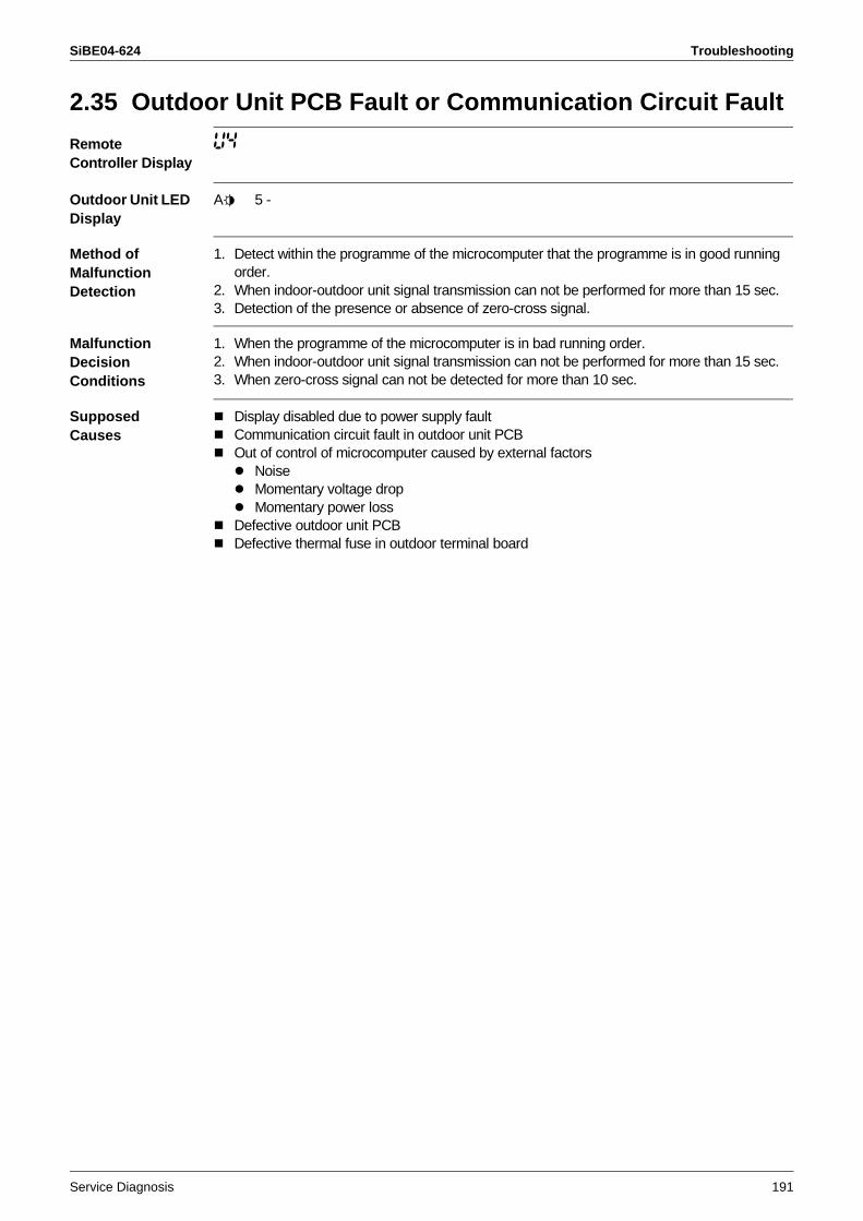
SiBE04-624 Troubleshooting
Service Diagnosis 191
2.35 Outdoor Unit PCB Fault or Communication Circuit Fault
Remote Controller Display
U4
Outdoor Unit LED Display
A5 5 -
Method of Malfunction Detection
1. Detect within the programme of the microcomputer that the programme is in good running order.
2. When indoor-outdoor unit signal transmission can not be performed for more than 15 sec.3. Detection of the presence or absence of zero-cross signal.
Malfunction Decision Conditions
1. When the programme of the microcomputer is in bad running order.2. When indoor-outdoor unit signal transmission can not be performed for more than 15 sec.3. When zero-cross signal can not be detected for more than 10 sec.
Supposed Causes
Display disabled due to power supply faultCommunication circuit fault in outdoor unit PCBOut of control of microcomputer caused by external factors
NoiseMomentary voltage dropMomentary power loss
Defective outdoor unit PCBDefective thermal fuse in outdoor terminal board
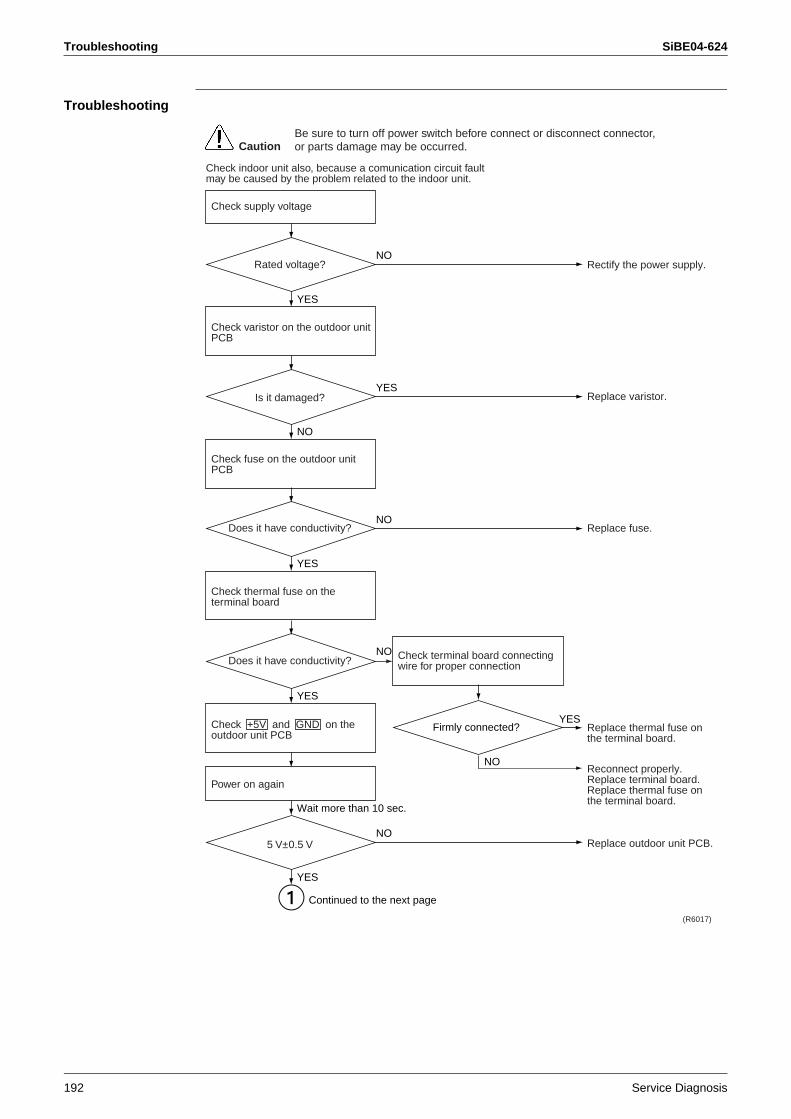
Troubleshooting SiBE04-624
192 Service Diagnosis
Troubleshooting
YES
Rectify the power supply.
Replace varistor.
Replace fuse.
Replace thermal fuse on the terminal board.
Reconnect properly. Replace terminal board. Replace thermal fuse on the terminal board.
Replace outdoor unit PCB.
(R6017)
CautionBe sure to turn off power switch before connect or disconnect connector, or parts damage may be occurred.
Check supply voltage
Check indoor unit also, because a comunication circuit fault may be caused by the problem related to the indoor unit.
Rated voltage?NO
NO
Firmly connected?
NO
NO
Check varistor on the outdoor unit PCB
Is it damaged?YES
YES
Check fuse on the outdoor unit PCB
Check terminal board connecting wire for proper connection
Does it have conductivity?NO
YES
Wait more than 10 sec.
Check thermal fuse on the terminal board
Does it have conductivity?
YES
Continued to the next page
YES
5 V±0.5 VNO
Check +5V and GND on the outdoor unit PCB
Power on again
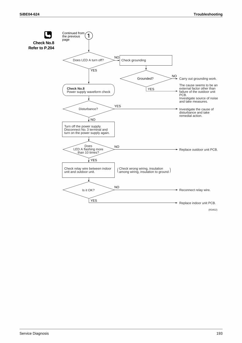
SiBE04-624 Troubleshooting
Service Diagnosis 193
Check No.8Refer to P.204
NO
Carry out grounding work.
The cause seems to be an external factor other than failure of the outdoor unit PCB.Investigate source of noise and take measures.
Investigate the cause of disturbance and take remedial action.
Replace outdoor unit PCB.
Reconnect relay wire.
Replace indoor unit PCB.
(R3452)
Disturbance?YES
NO
Grounded?
YES
YES
Turn off the power supply. Disconnect No. 3 terminal and turn on the power supply again.
DoesLED A flashing more
than 10 times?
NO
YES
Check relay wire between indoor unit and outdoor unit.
Check wrong wiring, insulation among wiring, insulation to ground
Check grounding
Is it OK?NO
YES
Does LED A turn off?
Continued fromthe previouspage
NO
Check No.8Power supply waveform check
( )
Troubleshooting SiBE04-624
194 Service Diagnosis
2.36 Signal Transmission Error on Outdoor Unit PCB
Remote Controller Display
U7
Outdoor Unit LED Display
A5 55 ( - )
Method of Malfunction Detection
Communication error between microcomputer mounted on the main body and inverter.
Malfunction Decision Conditions
When the data sent from the microcomputer of the inverter can not be received 15 times successively or for 15 sec, the machine shuts down.Fault counter is reset when the data from the microcomputer of the inverter can be successfully received.
Supposed Causes
Defective outdoor unit PCBDisconnection or breakage of harness between PCBs
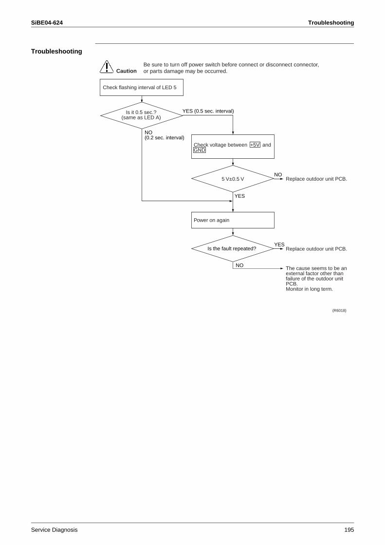
SiBE04-624 Troubleshooting
Service Diagnosis 195
Troubleshooting
Replace outdoor unit PCB.
Replace outdoor unit PCB.
The cause seems to be an external factor other than failure of the outdoor unit PCB.Monitor in long term.
(R6018)
CautionBe sure to turn off power switch before connect or disconnect connector, or parts damage may be occurred.
Is the fault repeated?
NO
NO(0.2 sec. interval)
Check flashing interval of LED 5
Is it 0.5 sec.?(same as LED A)
YES (0.5 sec. interval)
5 V±0.5 V
Check voltage between +5V and GND
YES
NO
YES
Power on again
Troubleshooting SiBE04-624
196 Service Diagnosis
2.37 Fan Motor System Fault / Fan Lock
Remote Controller Display
P9
Outdoor Unit LED Display
A5 55
Method of Malfunction Detection
During humidification fan motor running, fan motor system fault is identified based on the fan speed (rpm) detected by Hall IC.
Malfunction Decision Conditions
<Humidification fan>When fan speed does not reach 100 rpm within 7 sec. after fan motor start up.
Supposed Causes
<Humidification fan>Defective motor for humidification fanBreakage of relay harness or loose connectorDetection fault of fan speed due to defective outdoor unit PCB
Troubleshooting
Check No.23Refer to P.211
(R6019)
CautionBe sure to turn off power switch before connect or disconnect connector, or parts damage may be occurred.
YES
YES
YES
YES
Reconnect properly.
Replace hymidifying fan assembly.
Replace outdoor fan, humidification fan, outdoor unit PCB.
Replace outdoor unit PCB.
Procedure complete.
Is humidificationfan harness S72
connected?
<Others>
<Humidification fan>
<Humidification fan>
Rotate fan by handafter removing it
Check No.23Check for the rotation pulse input of outdoor unit PCB
NO
NO
NO
NO
Does it rotate?
Stop
Is fuse forpower supply of fan(FU2)
blown?
Does it rotate smoothly?
After assembling, run the fan
Run the humidifying operation.
SiBE04-624 Troubleshooting
Service Diagnosis 197
2.38 Heater Wire Fault
Remote Controller Display
PA
Outdoor Unit LED Display
A5 55
Method of Malfunction Detection
A fault is identified when the outlet temperature of humidification fan does not reach a certain temperature within a given time after the heater turned on.
Malfunction Decision Conditions
When the temperature detected by the thermistor is lower than the outdoor temperature (at heater turned off) + 6°C, and this condition continues for 30 min.
Supposed Causes
Breakage of heater filamentBreakage of heater harnessAbnormal temperature detected by outdoor temperature thermistorAbnormal temperature detected by humidification fan outlet thermistorDamaged main relayBlown thermal fuseDamaged heater control partExtremely low voltage
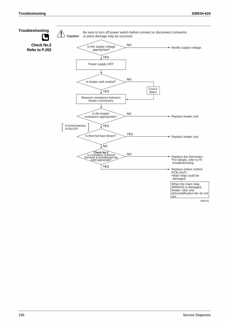
Troubleshooting SiBE04-624
198 Service Diagnosis
Troubleshooting
Check No.2Refer to P.202
(R6020)
CautionBe sure to turn off power switch before connect or disconnect connector, or parts damage may be occurred.
YES
YES
YES
Modify supply voltage.
Replace heater unit.
Replace heater unit.
Replace the thermistor.*For details, refer to PH troubleshooting
Replace indoor control PCB (A1P).*Main relay could be damaged.
When the main relay (MRM10) is damaged, heater, rotor and dehumidification fan do not run.
Is the supply voltage appropriate?
Power supply OFF
YES
NO
NO
NO
NO
Is the heaterresistance appropriate?
At normal temperature:44.6Ω±10%[ ]
Is thermal fuse blown?
NO
YES
Check No.2Is a resistance of thermal
thermistor at humidification fanoutlet appropriate?
Is heater well cooled?
Cool it down.
Measure resistance betweenheater connectors
SiBE04-624 Troubleshooting
Service Diagnosis 199
2.39 Humidification Fan Outlet Thermistor Fault / Abnormal Heater Temperature
Remote Controller Display
PH
Outdoor Unit LED Display
A5 55
Method of Malfunction Detection
Detect short circuit and wire breakage of humidification thermistor.When humidification fan outlet temperature becomes high, this condition is identified as an abnormal heater temperature fault.
Malfunction Decision Conditions
When power is supplied and the thermistor input is 4.90 V or more, or 0.06 V or less.If the humidification fan outlet temperature is more than 90°C, this condition is identified as abnormal heater temperature fault.
Supposed Causes
Short circuit and wire breakage of humidification thermistorDisconnected connectorHeater has a high powerThermistor temperature detection errorDefective rotor motorDefective dehumidification fan motorDefective heater control partDefective humidification fan
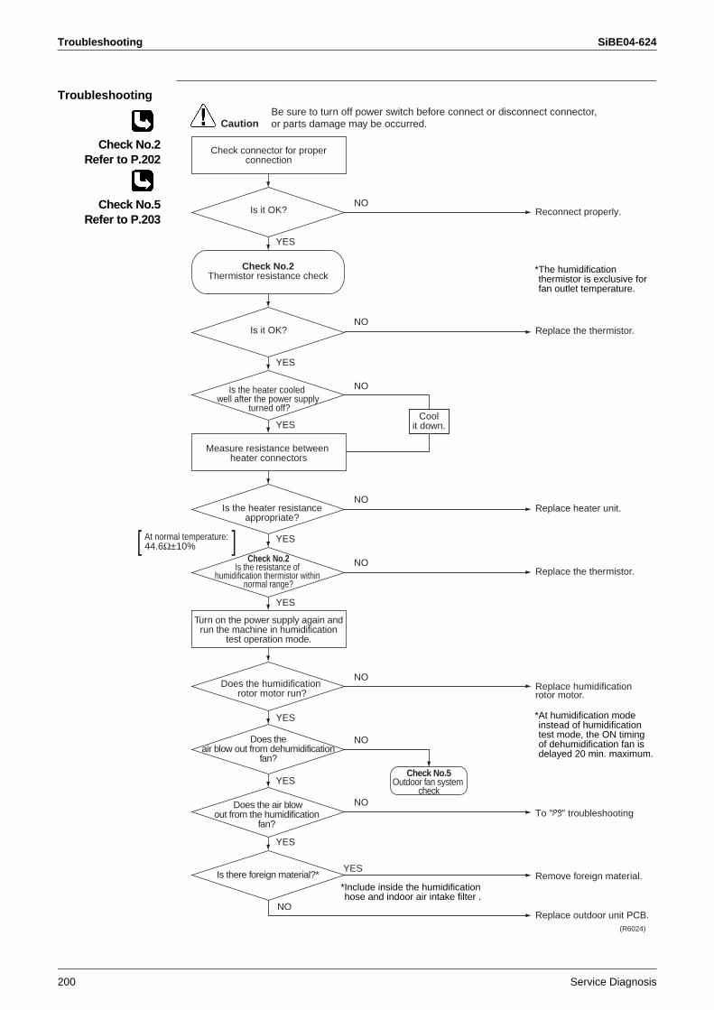
Troubleshooting SiBE04-624
200 Service Diagnosis
Troubleshooting
Check connector for proper connection
Is it OK?
Is it OK?
Coolit down.
Check No.5Outdoor fan system
check
YES
YES
YES
YES
YES
YES
YES
YES
YES
NO
NO
NO
NO
NO
NO
NO
NO
NO
Measure resistance between heater connectors
Turn on the power supply again and run the machine in humidification
test operation mode.
Is the heater resistance appropriate?
Does the humidification rotor motor run?
Does theair blow out from dehumidification
fan?
Does the air blowout from the humidification
fan?
Is there foreign material?*
Check No.2Is the resistance of
humidification thermistor within normal range?
Check No.2Thermistor resistance check
Is the heater cooled well after the power supply
turned off?
Reconnect properly.
*The humidification thermistor is exclusive for fan outlet temperature.
Replace the thermistor.
Replace heater unit.
Replace the thermistor.
Replace humidification rotor motor.
*At humidification mode instead of humidification test mode, the ON timing of dehumidification fan is delayed 20 min. maximum.
To "P9" troubleshooting
Remove foreign material.
Replace outdoor unit PCB.
*Include inside the humidification hose and indoor air intake filter .
CautionBe sure to turn off power switch before connect or disconnect connector, or parts damage may be occurred.
(R6024)
At normal temperature:44.6Ω±10%[ ]
Check No.2Refer to P.202
Check No.5Refer to P.203
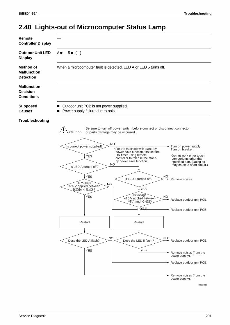
SiBE04-624 Troubleshooting
Service Diagnosis 201
2.40 Lights-out of Microcomputer Status Lamp
Remote Controller Display
—
Outdoor Unit LED Display
A1 51 ( - )
Method of Malfunction Detection
When a microcomputer fault is detected, LED A or LED 5 turns off.
Malfunction Decision Conditions
Supposed Causes
Outdoor unit PCB is not power suppliedPower supply failure due to noise
Troubleshooting
CautionBe sure to turn off power switch before connect or disconnect connector, or parts damage may be occurred.
(R6021)
Is correct power supplied?*For the machine with stand-by power save function, first set the ON timer using remote controller to release the stand-by power save function.
Is LED A turned off?
Is LED 5 turned off?
YES
YES YES
YES
YES
YES
YES
Dose the LED A flash? Dose the LED 5 flash?NO
Is voltageof 5 V applied between
+5V and GND ?
Restart Restart
NO
NO
NO
NO
NO
NO
Is voltageof 5 V applied between
+5V and GND ?
Turn on power supply.Turn on breaker.
*Do not work on or touch components other than specified part. (Doing so may cause a short circuit.)
Remove noises.
Replace outdoor unit PCB.
Replace outdoor unit PCB.
Replace outdoor unit PCB.
Remove noises (from the power supply).
Replace outdoor unit PCB.
Remove noises (from the power supply).
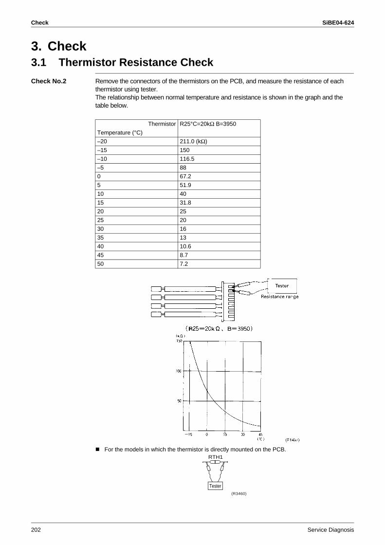
Check SiBE04-624
202 Service Diagnosis
3. Check3.1 Thermistor Resistance Check
Check No.2 Remove the connectors of the thermistors on the PCB, and measure the resistance of each thermistor using tester.The relationship between normal temperature and resistance is shown in the graph and the table below.
For the models in which the thermistor is directly mounted on the PCB.
Thermistor R25°C=20kΩ B=3950
Temperature (°C)
–20 211.0 (kΩ)
–15 150
–10 116.5
–5 88
0 67.2
5 51.9
10 40
15 31.8
20 25
25 20
30 16
35 13
40 10.6
45 8.7
50 7.2
RTH1
Tester(R3460)
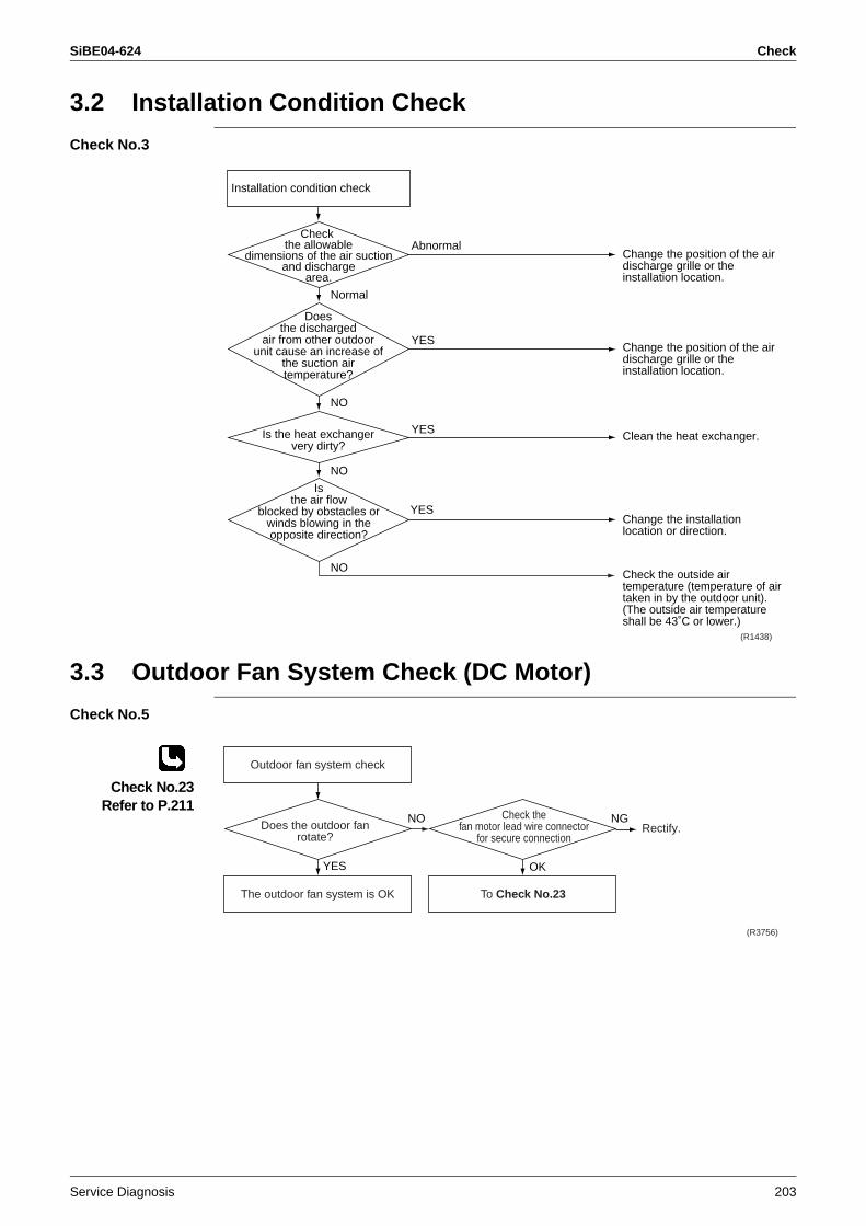
SiBE04-624 Check
Service Diagnosis 203
3.2 Installation Condition Check
Check No.3
3.3 Outdoor Fan System Check (DC Motor)
Check No.5
Check No.23Refer to P.211
Installation condition check
Normal
Change the position of the air discharge grille or the installation location.
Change the position of the air discharge grille or the installation location.
Clean the heat exchanger.
Change the installation location or direction.
Check the outside air temperature (temperature of air taken in by the outdoor unit). (The outside air temperature shall be 43˚C or lower.)
Check the allowable
dimensions of the air suctionand discharge
area.
Isthe air flow
blocked by obstacles orwinds blowing in theopposite direction?
(R1438)
Abnormal
YES
YES
YES
Doesthe discharged
air from other outdoorunit cause an increase of
the suction airtemperature?
NO
NO
NO
Is the heat exchangervery dirty?
Rectify.
(R3756)
The outdoor fan system is OK
Outdoor fan system check
To Check No.23
NO NGDoes the outdoor fan
rotate?
YES
Check thefan motor lead wire connector
for secure connection
OK
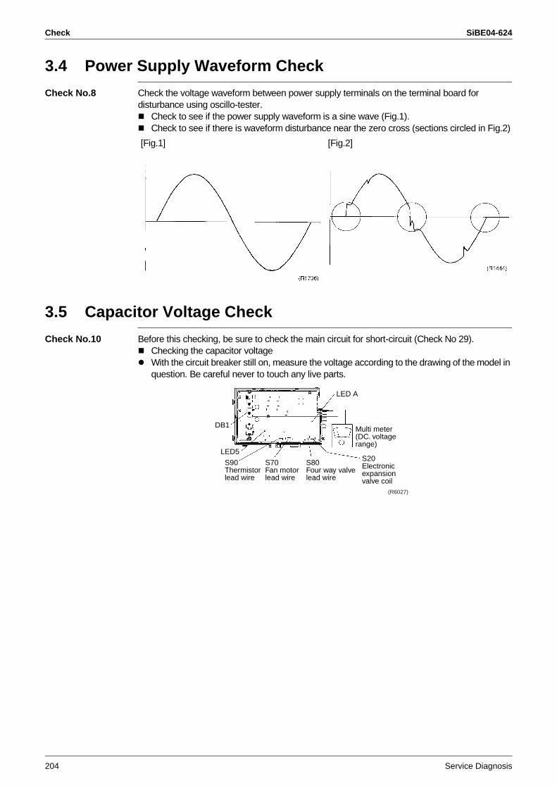
Check SiBE04-624
204 Service Diagnosis
3.4 Power Supply Waveform Check
Check No.8 Check the voltage waveform between power supply terminals on the terminal board for disturbance using oscillo-tester.
Check to see if the power supply waveform is a sine wave (Fig.1).Check to see if there is waveform disturbance near the zero cross (sections circled in Fig.2)
3.5 Capacitor Voltage Check
Check No.10 Before this checking, be sure to check the main circuit for short-circuit (Check No 29).Checking the capacitor voltageWith the circuit breaker still on, measure the voltage according to the drawing of the model in question. Be careful never to touch any live parts.
[Fig.1] [Fig.2]
DB1
LED A
LED5
S90Thermistorlead wire
S70Fan motorlead wire
S80Four way valvelead wire
S20Electronicexpansionvalve coil
Multi meter (DC. voltage range)
(R6027)
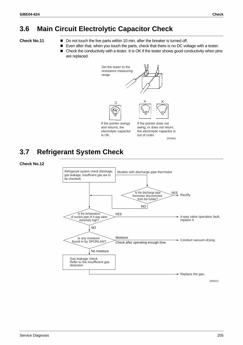
SiBE04-624 Check
Service Diagnosis 205
3.6 Main Circuit Electrolytic Capacitor Check
Check No.11 Do not touch the live parts within 10 min. after the breaker is turned off.Even after that, when you touch the parts, check that there is no DC voltage with a tester.Check the conductivity with a tester. It is OK if the tester shows good conductivity when pins are replaced.
3.7 Refrigerant System Check
Check No.12
Set the tester to the resistance measuring range
If the pointer swings and returns, the electrolytic capacitor is OK.
If the pointer does not swing, or does not return, the electrolytic capacitor is out of order.
(R3466)
Rectify.
4-way valve operation fault, replace it.
Conduct vacuum drying.
Replace the gas.
(R6022)
Refrigerant system check (blockage, gas leakage, insufficient gas are to be checked)
Is the temperatureof suction pipe of 4-way valve
extremely high?
Gas leakage checkRefer to the insufficient gas detection
NO
YES
NO
Is the discharge pipethermistor disconnected
from the holder?
YES
Is any moisture found in by SPORLAN?
No moisture
Moisture
Check after operating enough time.
Models with discharge pipe thermistor
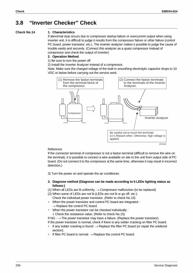
Check SiBE04-624
206 Service Diagnosis
3.8 “Inverter Checker” Check
Check No.14 1. CharacteristicsIf abnormal stop occurs due to compressor startup failure or overcurrent output when using inverter unit, it is difficult to judge it results from the compressor failure or other failure (control PC board, power transistor, etc.). The inverter analyzer makes it possible to judge the cause of trouble easily and securely. (Connect this analyzer as a quasi compressor instead of compressor and check the output of inverter)2. Operation Method1) Be sure to turn the power off.2) Install the Inverter Analyzer instead of a compressor.Note: Make sure the charged voltage of the built-in smoothing electrolytic capacitor drops to 10 VDC or below before carrying out the service work.
ReferenceIf the connector terminal of compressor is not a faston terminal (difficult to remove the wire on the terminal), it is possible to connect a wire available on site to the unit from output side of PC board. (Do not connect it to the compressor at the same time, otherwise it may result in incorrect detection.)
3) Turn the power on and operate the air conditioner.
3. Diagnose method (Diagnose can be made according to 6 LEDs lighting status as follows:)
(1) When all LEDs are lit uniformly, → Compressor malfunction (to be replaced)(2) When some of LEDs are not lit (LEDs are not lit or go off, etc.):
Check the individual power transistor. (Refer to check No.15)∗ When the power transistor and control PC board are integrated :
→ Replace the control PC board.∗ When the power transistor can be checked individually :
↓ Check the resistance value. (Refer to check No.15)If NG : → The power transistor may have a failure. (Replace the power transistor).If the power transistor is normal, check if there is any solder cracking on filter PC board.∗ If any solder cracking is found: → Replace the filter PC board (or repair the soldered
section).∗ If filter PC board is normal: → Replace the control PC board.
(1) Remove the faston terminalsfrom the terminal block ofthe compressor.
(2) Connect the faston terminalsto the terminals of the InverterAnalyzer.
Inverter Analyzer
Be careful not to touch the terminals(U,V,W)each other. Otherwise, high voltage is applied.
Compressor
(R5160)
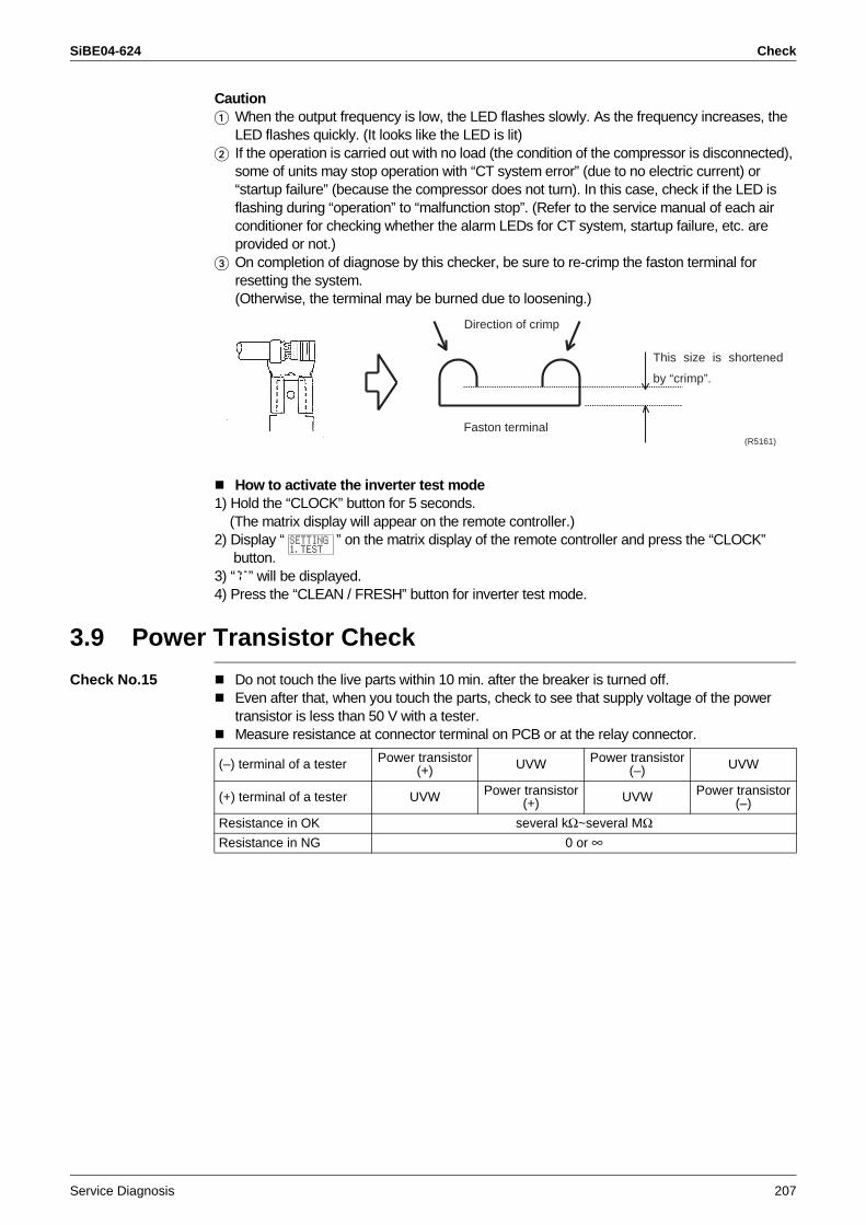
SiBE04-624 Check
Service Diagnosis 207
Caution When the output frequency is low, the LED flashes slowly. As the frequency increases, the
LED flashes quickly. (It looks like the LED is lit) If the operation is carried out with no load (the condition of the compressor is disconnected),
some of units may stop operation with “CT system error” (due to no electric current) or “startup failure” (because the compressor does not turn). In this case, check if the LED is flashing during “operation” to “malfunction stop”. (Refer to the service manual of each air conditioner for checking whether the alarm LEDs for CT system, startup failure, etc. are provided or not.)
On completion of diagnose by this checker, be sure to re-crimp the faston terminal for resetting the system.(Otherwise, the terminal may be burned due to loosening.)
How to activate the inverter test mode1) Hold the “CLOCK” button for 5 seconds. (The matrix display will appear on the remote controller.)2) Display “ ” on the matrix display of the remote controller and press the “CLOCK” button.3) “T” will be displayed.4) Press the “CLEAN / FRESH” button for inverter test mode.
3.9 Power Transistor Check
Check No.15 Do not touch the live parts within 10 min. after the breaker is turned off.Even after that, when you touch the parts, check to see that supply voltage of the power transistor is less than 50 V with a tester.Measure resistance at connector terminal on PCB or at the relay connector.
Direction of crimp
This size is shortened
by “crimp”.
Faston terminal(R5161)
(–) terminal of a tester Power transistor(+) UVW Power transistor
(–) UVW
(+) terminal of a tester UVW Power transistor(+) UVW Power transistor
(–)
Resistance in OK several kΩ~several MΩResistance in NG 0 or ∞
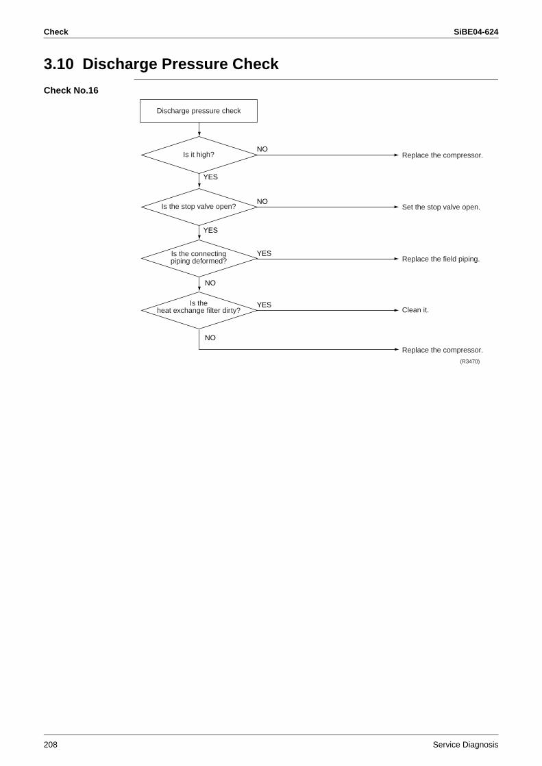
Check SiBE04-624
208 Service Diagnosis
3.10 Discharge Pressure Check
Check No.16
Replace the compressor.
Set the stop valve open.
Replace the field piping.
Clean it.
Replace the compressor.
Discharge pressure check
Is it high?
YES
YES
NO
NO
NO
NOIs the stop valve open?
Is the connectingpiping deformed?
Is theheat exchange filter dirty?
YES
YES
(R3470)
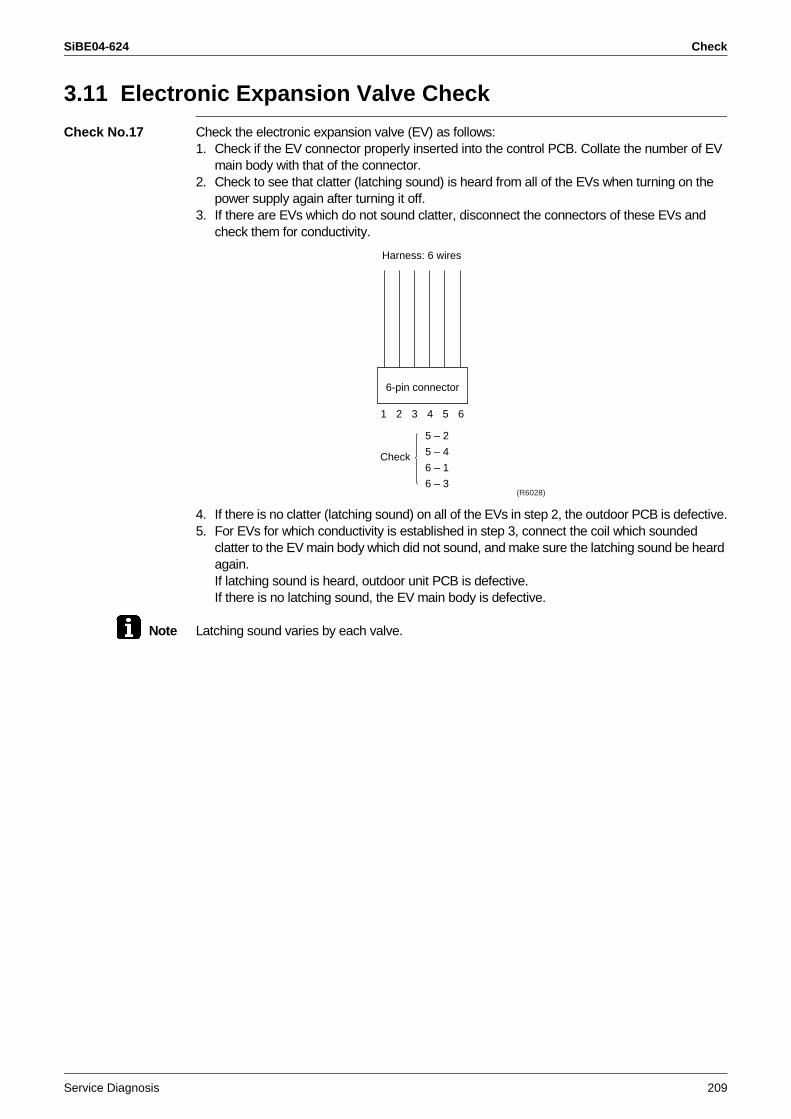
SiBE04-624 Check
Service Diagnosis 209
3.11 Electronic Expansion Valve Check
Check No.17 Check the electronic expansion valve (EV) as follows:1. Check if the EV connector properly inserted into the control PCB. Collate the number of EV
main body with that of the connector.2. Check to see that clatter (latching sound) is heard from all of the EVs when turning on the
power supply again after turning it off.3. If there are EVs which do not sound clatter, disconnect the connectors of these EVs and
check them for conductivity.
4. If there is no clatter (latching sound) on all of the EVs in step 2, the outdoor PCB is defective.5. For EVs for which conductivity is established in step 3, connect the coil which sounded
clatter to the EV main body which did not sound, and make sure the latching sound be heard again.If latching sound is heard, outdoor unit PCB is defective.If there is no latching sound, the EV main body is defective.
Note Latching sound varies by each valve.
6-pin connector
1 2 3 4 5 6
Harness: 6 wires
Check
5 – 2
5 – 4
6 – 1
6 – 3(R6028)
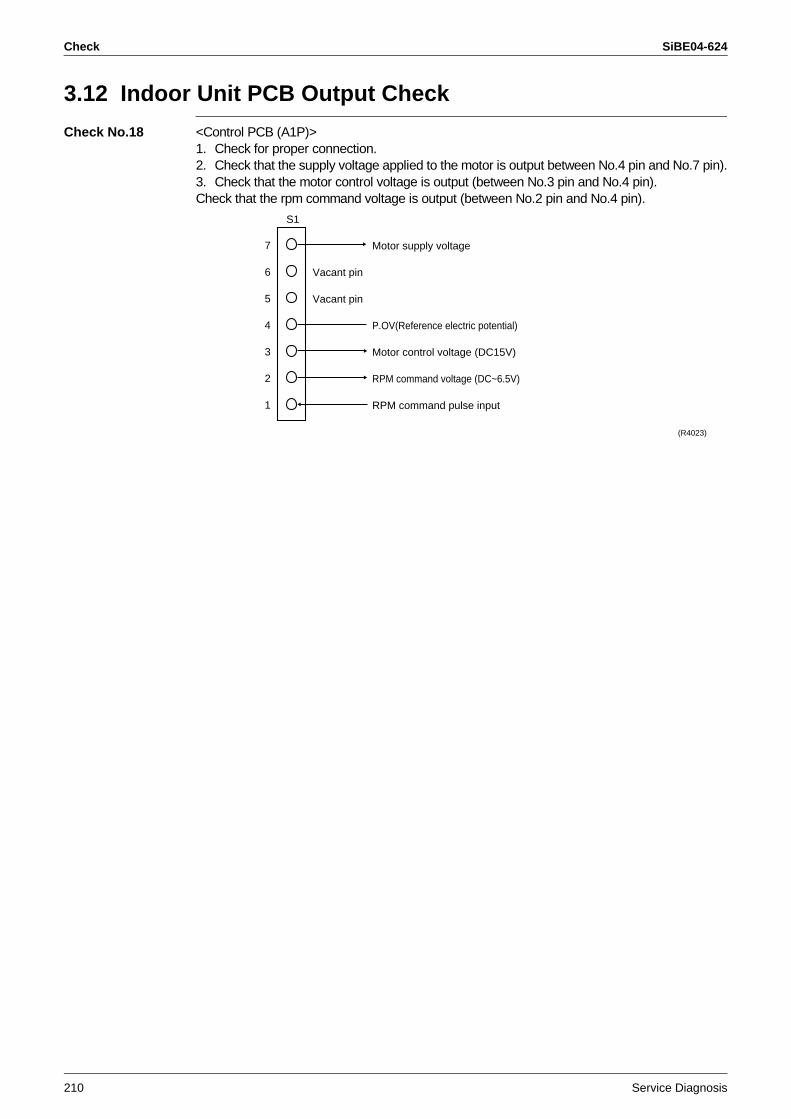
Check SiBE04-624
210 Service Diagnosis
3.12 Indoor Unit PCB Output Check
Check No.18 <Control PCB (A1P)>1. Check for proper connection.2. Check that the supply voltage applied to the motor is output between No.4 pin and No.7 pin).3. Check that the motor control voltage is output (between No.3 pin and No.4 pin).Check that the rpm command voltage is output (between No.2 pin and No.4 pin).
(R4023)
7
6
5
4
3
2
1
Motor supply voltage
Vacant pin
Vacant pin
P.OV(Reference electric potential)
Motor control voltage (DC15V)
RPM command voltage (DC~6.5V)
RPM command pulse input
S1
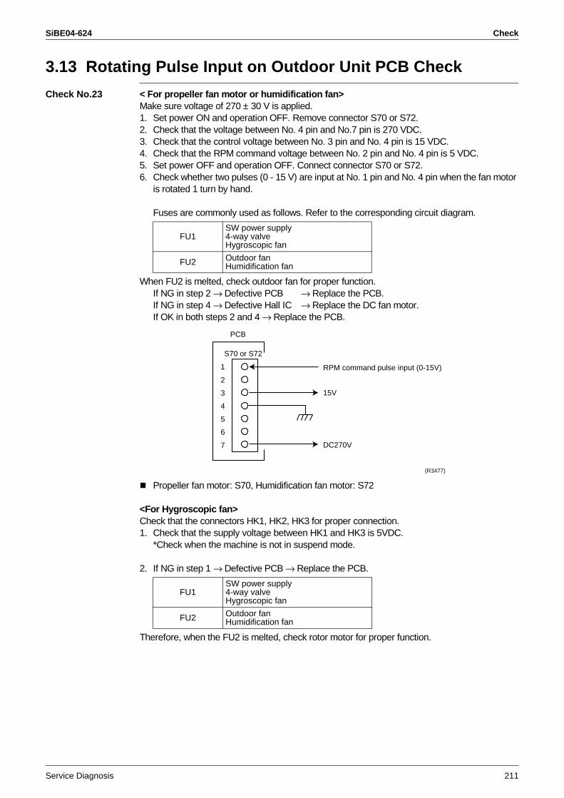
SiBE04-624 Check
Service Diagnosis 211
3.13 Rotating Pulse Input on Outdoor Unit PCB Check
Check No.23 < For propeller fan motor or humidification fan>Make sure voltage of 270 ± 30 V is applied.1. Set power ON and operation OFF. Remove connector S70 or S72.2. Check that the voltage between No. 4 pin and No.7 pin is 270 VDC.3. Check that the control voltage between No. 3 pin and No. 4 pin is 15 VDC.4. Check that the RPM command voltage between No. 2 pin and No. 4 pin is 5 VDC.5. Set power OFF and operation OFF. Connect connector S70 or S72.6. Check whether two pulses (0 - 15 V) are input at No. 1 pin and No. 4 pin when the fan motor
is rotated 1 turn by hand.
Fuses are commonly used as follows. Refer to the corresponding circuit diagram.
When FU2 is melted, check outdoor fan for proper function.If NG in step 2 → Defective PCB → Replace the PCB.If NG in step 4 → Defective Hall IC → Replace the DC fan motor.If OK in both steps 2 and 4 → Replace the PCB.
Propeller fan motor: S70, Humidification fan motor: S72
<For Hygroscopic fan>Check that the connectors HK1, HK2, HK3 for proper connection.1. Check that the supply voltage between HK1 and HK3 is 5VDC.
*Check when the machine is not in suspend mode.
2. If NG in step 1 → Defective PCB → Replace the PCB.
Therefore, when the FU2 is melted, check rotor motor for proper function.
FU1SW power supply4-way valveHygroscopic fan
FU2 Outdoor fanHumidification fan
FU1SW power supply4-way valveHygroscopic fan
FU2 Outdoor fanHumidification fan
1
2
3
4
5
6
7
RPM command pulse input (0-15V)
15V
DC270V
(R3477)
S70 or S72
PCB
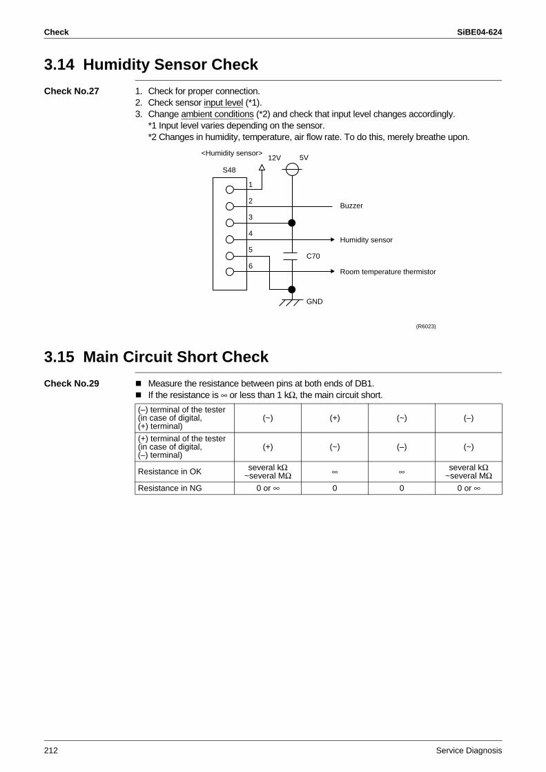
Check SiBE04-624
212 Service Diagnosis
3.14 Humidity Sensor Check
Check No.27 1. Check for proper connection.2. Check sensor input level (*1).3. Change ambient conditions (*2) and check that input level changes accordingly.
*1 Input level varies depending on the sensor.*2 Changes in humidity, temperature, air flow rate. To do this, merely breathe upon.
3.15 Main Circuit Short Check
Check No.29 Measure the resistance between pins at both ends of DB1.If the resistance is ∞ or less than 1 kΩ, the main circuit short.
1
2
3
4
5
6
Buzzer
Humidity sensor
Room temperature thermistor
5V<Humidity sensor>
S48
GND
12V
C70
(R6023)
(–) terminal of the tester (in case of digital,(+) terminal)
(~) (+) (~) (–)
(+) terminal of the tester (in case of digital,(–) terminal)
(+) (~) (–) (~)
Resistance in OK several kΩ ~several MΩ ∞ ∞ several kΩ
~several MΩResistance in NG 0 or ∞ 0 0 0 or ∞
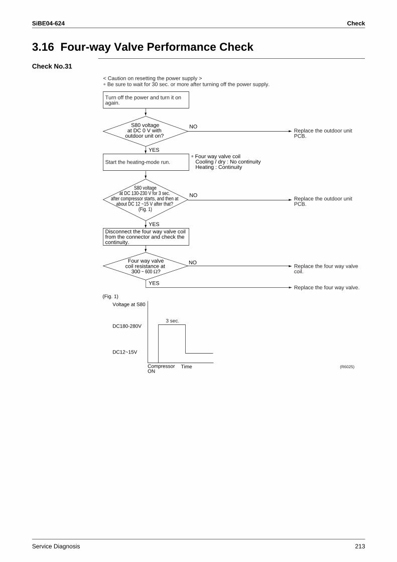
SiBE04-624 Check
Service Diagnosis 213
3.16 Four-way Valve Performance Check
Check No.31
Start the heating-mode run.
Replace the outdoor unit PCB.
Replace the four way valve coil.
Replace the four way valve.
(R6025)
NO
∗ Four way valve coil Cooling / dry : No continuity Heating : Continuity
YES
YES
Four way valvecoil resistance at
300 ~ 600 Ω?
NO
S80 voltageat DC 130-230 V for 3 sec.
after compressor starts, and then at about DC 12 ~15 V after that?
(Fig. 1)
Turn off the power and turn it on again.
Replace the outdoor unit PCB.
NO
YES
S80 voltageat DC 0 V with
outdoor unit on?
Disconnect the four way valve coil from the connector and check the continuity.
(Fig. 1)
Voltage at S80
DC180-280V
DC12~15V
TimeCompressorON
3 sec.
< Caution on resetting the power supply >∗ Be sure to wait for 30 sec. or more after turning off the power supply.
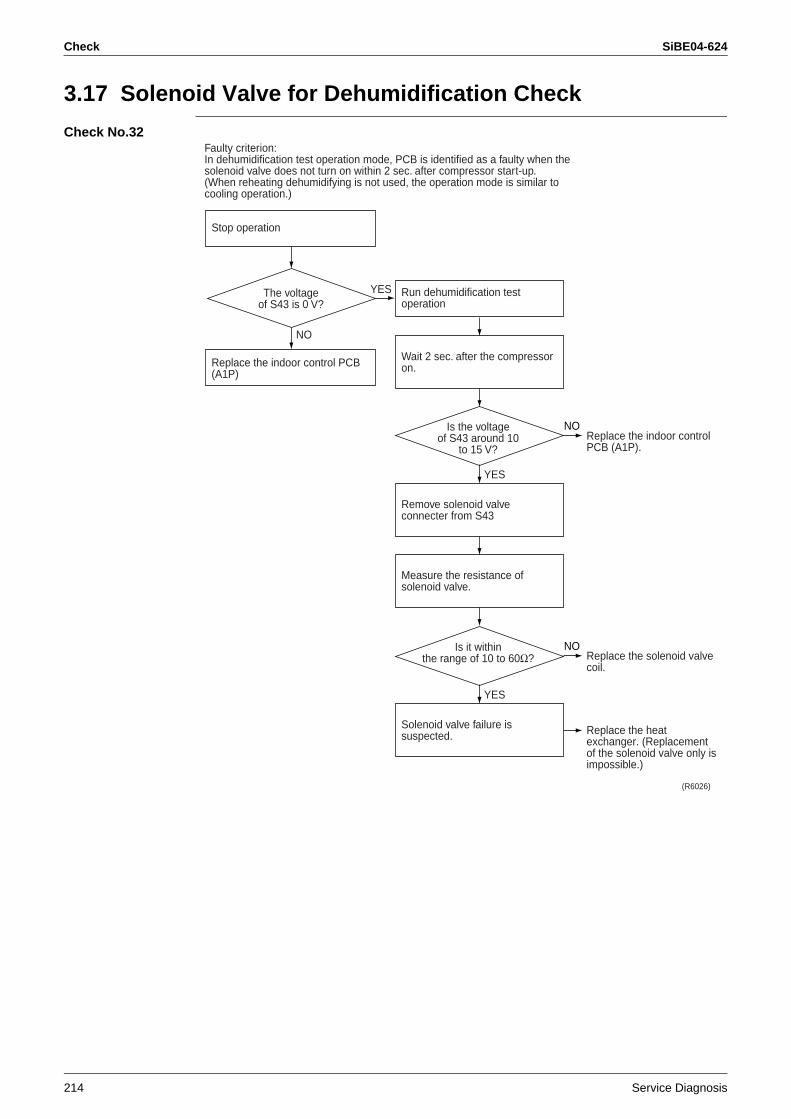
Check SiBE04-624
214 Service Diagnosis
3.17 Solenoid Valve for Dehumidification Check
Check No.32
Replace the indoor control PCB (A1P).
Replace the solenoid valve coil.
Replace the heat exchanger. (Replacement of the solenoid valve only is impossible.)
The voltageof S43 is 0 V?
(R6026)
Is the voltageof S43 around 10
to 15 V?
NO
Stop operation
Replace the indoor control PCB (A1P)
YES
NO
Wait 2 sec. after the compressor on.
Run dehumidification test operation
Measure the resistance of solenoid valve.
Remove solenoid valve connecter from S43
YES
Is it withinthe range of 10 to 60Ω?
NO
Solenoid valve failure is suspected.
YES
Faulty criterion:In dehumidification test operation mode, PCB is identified as a faulty when the solenoid valve does not turn on within 2 sec. after compressor start-up.(When reheating dehumidifying is not used, the operation mode is similar to cooling operation.)
SiBE04-624
Removal Procedure 215
Part 7Removal Procedure
1. Indoor Unit...........................................................................................2161.1 Removal of the Air Filters / Front panel................................................2161.2 Removal of the Upper Panel ................................................................2221.3 Removal of the Front Grille ..................................................................2251.4 Removal of the Assembly of the Open/Close Mechanism ...................2281.5 Removal of the Assembly of the Reduction Motor ...............................2301.6 Removal of the Electrical Box ..............................................................2331.7 Removal of the PCB.............................................................................2381.8 Removal of the Dehumidifying Solenoid Valve Coil .............................2441.9 Removal of the Connecting Duct..........................................................2451.10 Removal of the Drain Hose ..................................................................2471.11 Removal of the Swing Motor ................................................................2491.12 Removal of the Heat Exchanger ..........................................................2511.13 Removal of the Propeller Fan / Fan Motor ...........................................2541.14 Removal of Horizontal Blades / Vertical Blades ...................................2571.15 Removal of the Streamer Unit ..............................................................259
2. Outdoor Unit........................................................................................2632.1 Removal of the Humidify Unit...............................................................2632.2 Removal of the Heater Assembly / Humidifying Rotor
(Moisture Absorption Element) / Humidifying Rotor Motor ...................2662.3 Removal of the Humidifying Assembly.................................................2702.4 Removal of the Moisture Absorption Fan Motor...................................2732.5 Removal of the Propeller Fan / Fan Motor ...........................................2742.6 Removal of the Duct in Humidifier........................................................2792.7 Removal of the Electrical Box ..............................................................2802.8 Removal of the PCB.............................................................................2842.9 Removal of the Sound Blanket.............................................................2872.10 Remove the Thermistor Assembly .......................................................2892.11 Removal of the Reactor / Partition Plate ..............................................2912.12 Removal of the Four Way Valve...........................................................2922.13 Removal of the Expansion Valve .........................................................2942.14 Removal of the Compressor.................................................................295
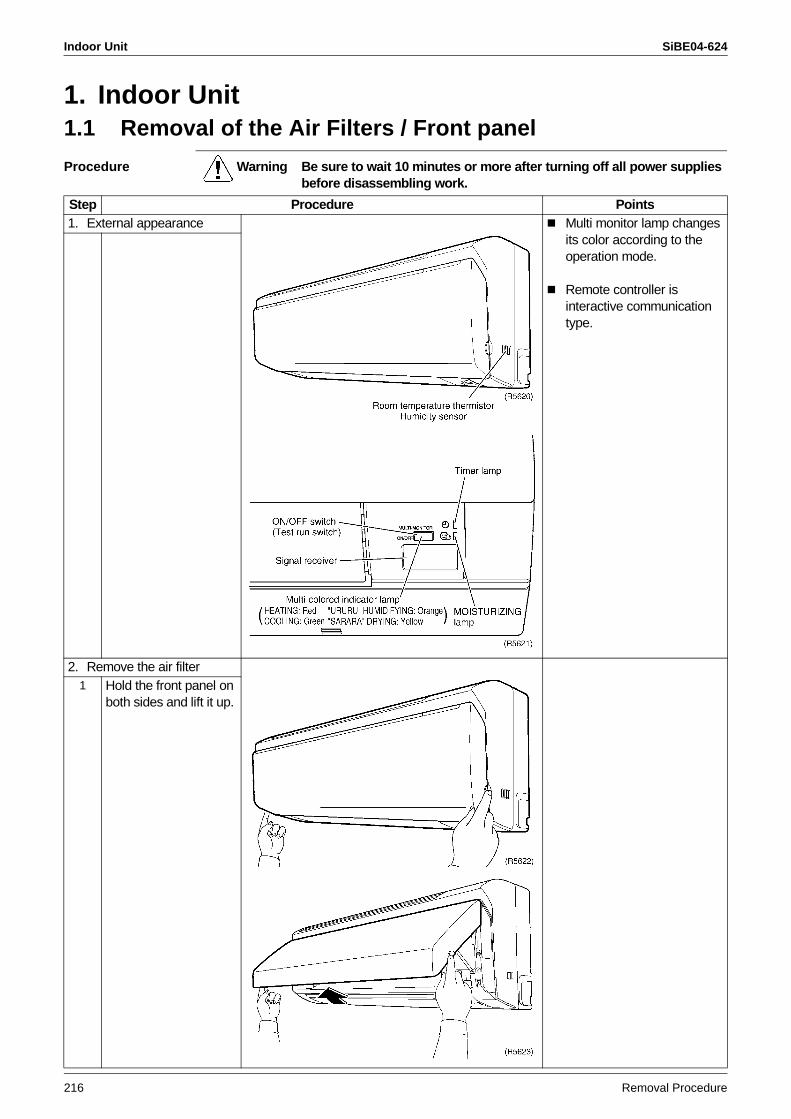
Indoor Unit SiBE04-624
216 Removal Procedure
1. Indoor Unit1.1 Removal of the Air Filters / Front panel
Procedure Warning Be sure to wait 10 minutes or more after turning off all power supplies before disassembling work.
Step Procedure Points1. External appearance Multi monitor lamp changes
its color according to the operation mode.
Remote controller is interactive communication type.
2. Remove the air filter1 Hold the front panel on
both sides and lift it up.
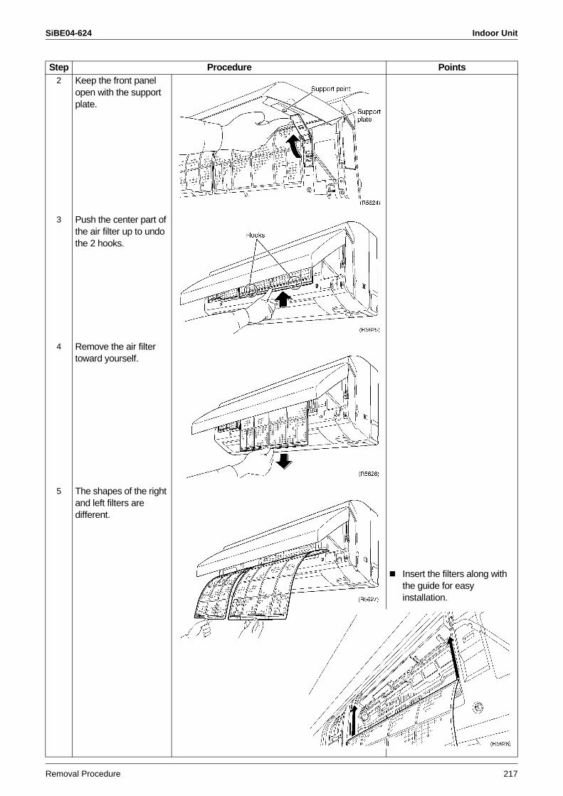
SiBE04-624 Indoor Unit
Removal Procedure 217
2 Keep the front panel open with the support plate.
3 Push the center part of the air filter up to undo the 2 hooks.
4 Remove the air filter toward yourself.
5 The shapes of the right and left filters are different.
Insert the filters along with the guide for easy installation.
Step Procedure Points
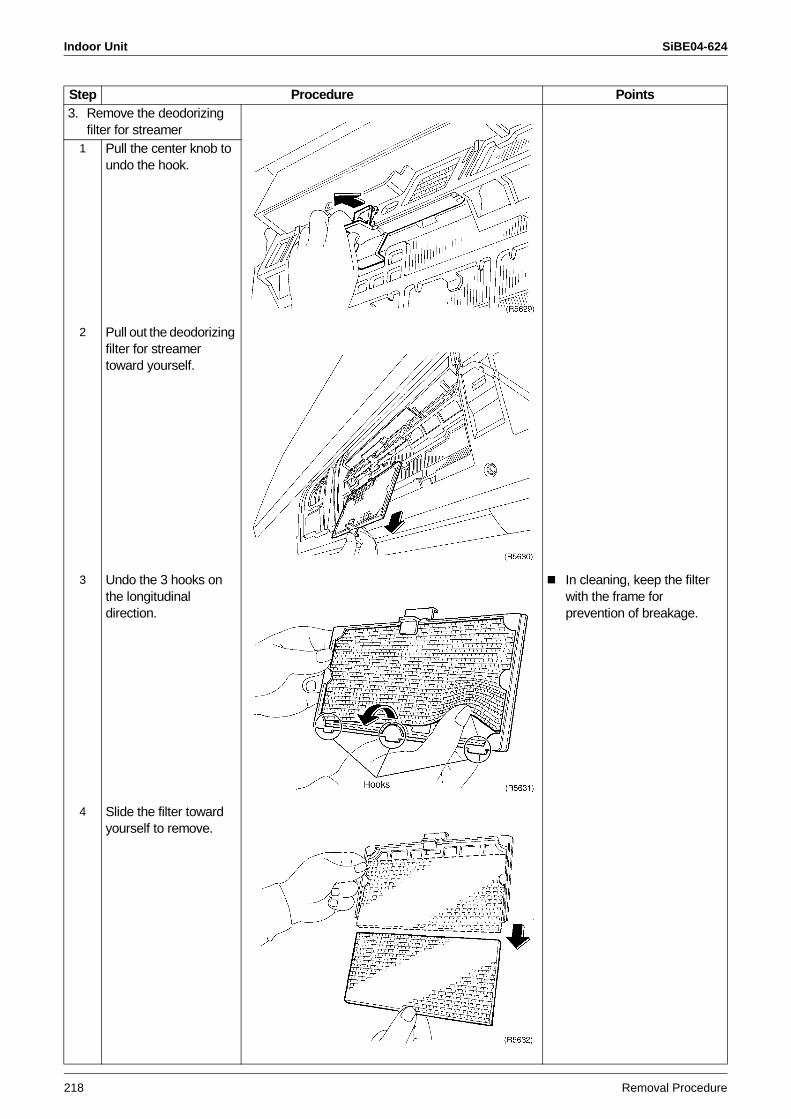
Indoor Unit SiBE04-624
218 Removal Procedure
3. Remove the deodorizing filter for streamer
1 Pull the center knob to undo the hook.
2 Pull out the deodorizing filter for streamer toward yourself.
3 Undo the 3 hooks on the longitudinal direction.
In cleaning, keep the filter with the frame for prevention of breakage.
4 Slide the filter toward yourself to remove.
Step Procedure Points
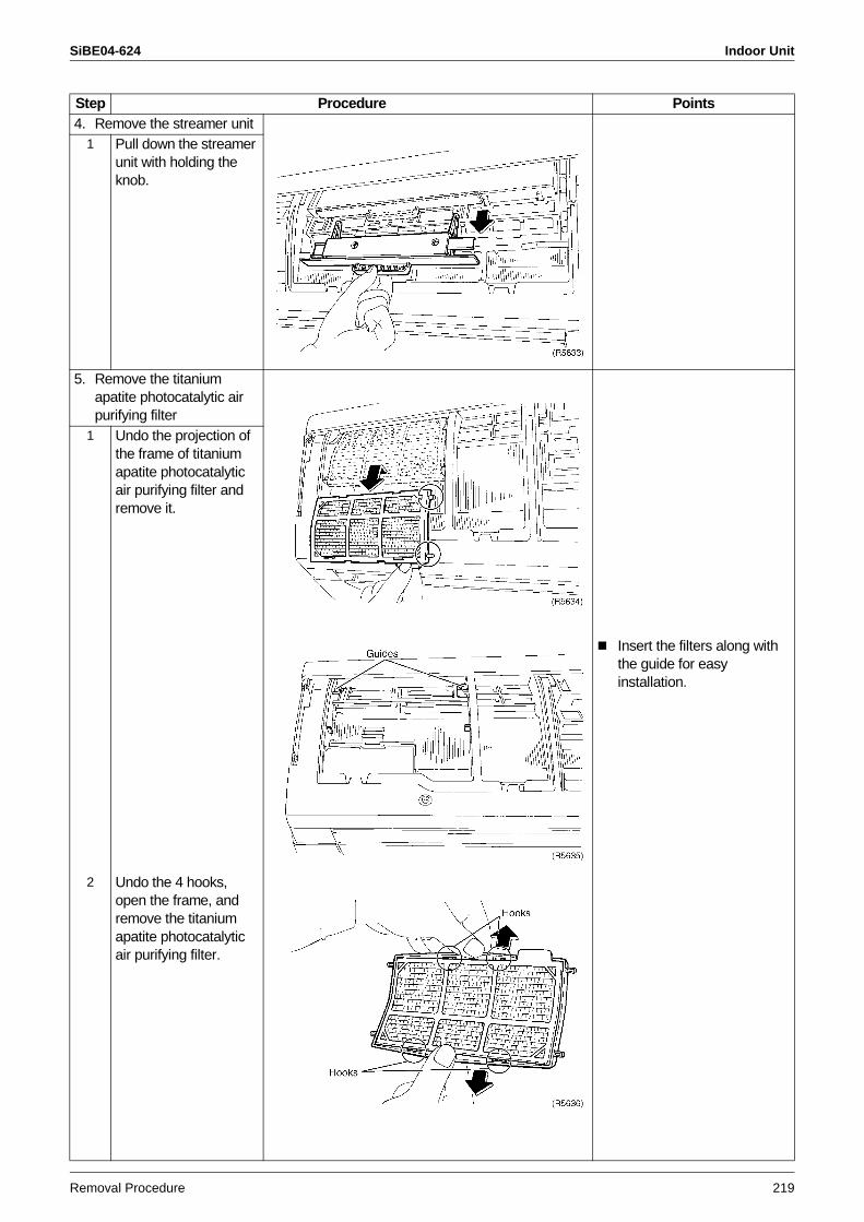
SiBE04-624 Indoor Unit
Removal Procedure 219
4. Remove the streamer unit1 Pull down the streamer
unit with holding the knob.
5. Remove the titanium apatite photocatalytic air purifying filter
1 Undo the projection of the frame of titanium apatite photocatalytic air purifying filter and remove it.
Insert the filters along with the guide for easy installation.
2 Undo the 4 hooks, open the frame, and remove the titanium apatite photocatalytic air purifying filter.
Step Procedure Points
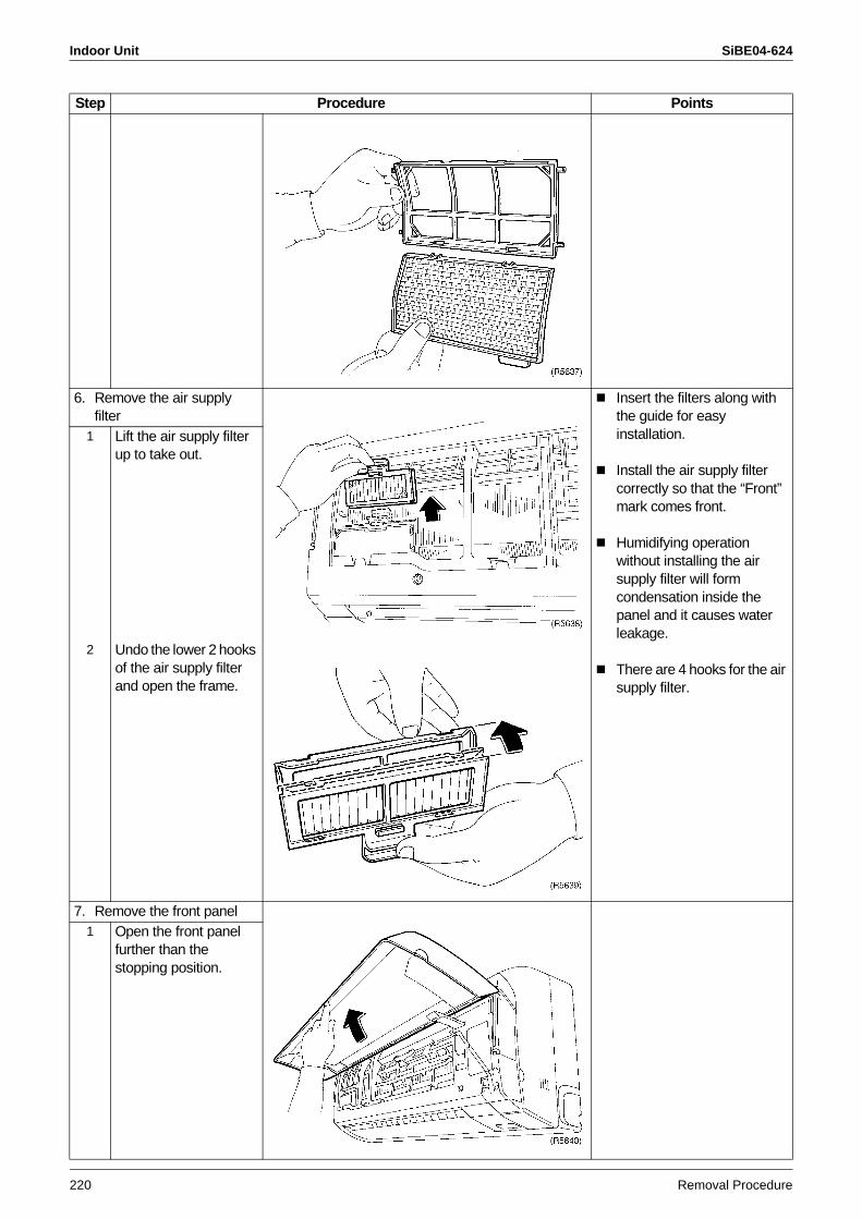
Indoor Unit SiBE04-624
220 Removal Procedure
6. Remove the air supply filter
Insert the filters along with the guide for easy installation.
Install the air supply filter correctly so that the “Front” mark comes front.
Humidifying operation without installing the air supply filter will form condensation inside the panel and it causes water leakage.
There are 4 hooks for the air supply filter.
1 Lift the air supply filter up to take out.
2 Undo the lower 2 hooks of the air supply filter and open the frame.
7. Remove the front panel1 Open the front panel
further than the stopping position.
Step Procedure Points
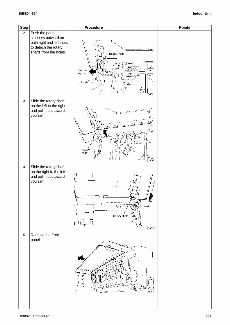
SiBE04-624 Indoor Unit
Removal Procedure 221
2 Push the panel stoppers outward on both right and left sides to detach the rotary shafts from the holes.
3 Slide the rotary shaft on the left to the right and pull it out toward yourself.
4 Slide the rotary shaft on the right to the left and pull it out toward yourself.
5 Remove the front panel.
Step Procedure Points
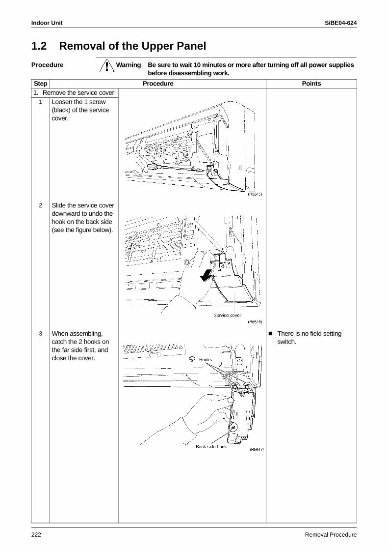
Indoor Unit SiBE04-624
222 Removal Procedure
1.2 Removal of the Upper Panel
Procedure Warning Be sure to wait 10 minutes or more after turning off all power supplies before disassembling work.
Step Procedure Points1. Remove the service cover
1 Loosen the 1 screw (black) of the service cover.
2 Slide the service cover downward to undo the hook on the back side (see the figure below).
3 When assembling, catch the 2 hooks on the far side first, and close the cover.
There is no field setting switch.
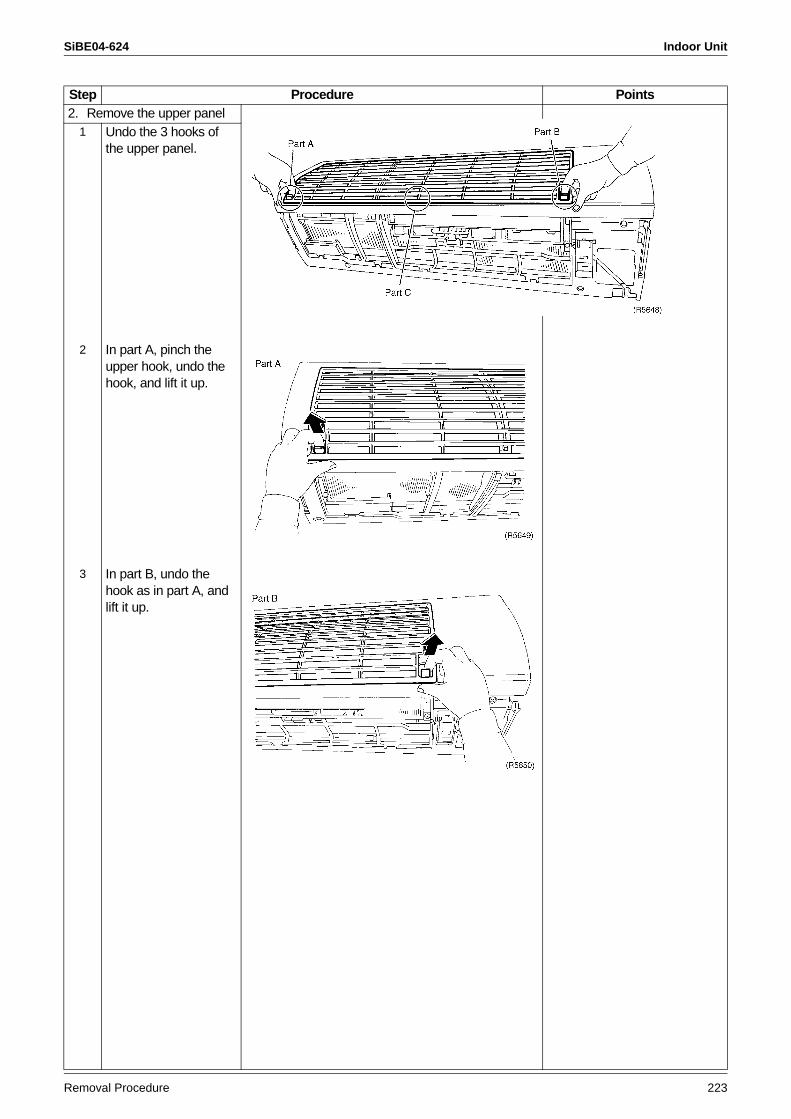
SiBE04-624 Indoor Unit
Removal Procedure 223
2. Remove the upper panel1 Undo the 3 hooks of
the upper panel.
2 In part A, pinch the upper hook, undo the hook, and lift it up.
3 In part B, undo the hook as in part A, and lift it up.
Step Procedure Points
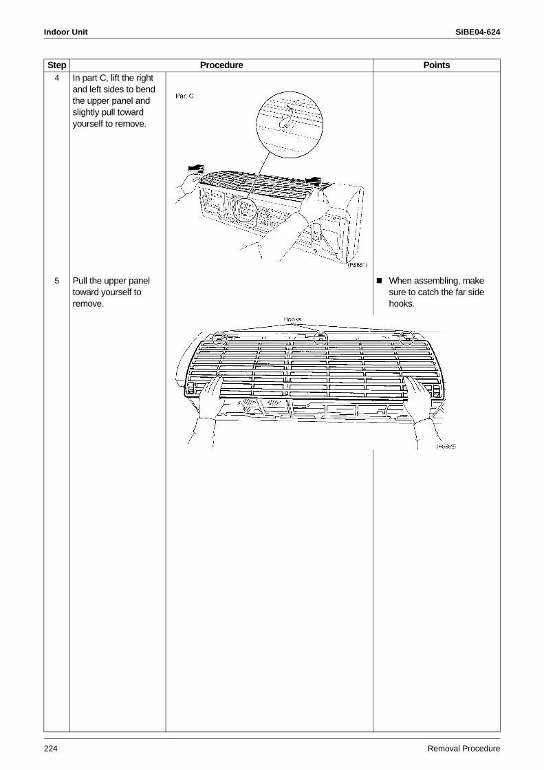
Indoor Unit SiBE04-624
224 Removal Procedure
4 In part C, lift the right and left sides to bend the upper panel and slightly pull toward yourself to remove.
5 Pull the upper panel toward yourself to remove.
When assembling, make sure to catch the far side hooks.
Step Procedure Points
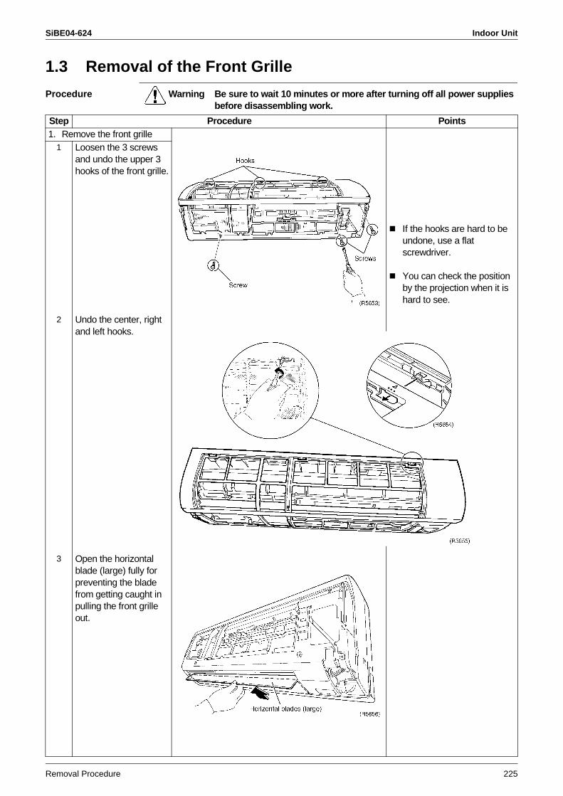
SiBE04-624 Indoor Unit
Removal Procedure 225
1.3 Removal of the Front Grille
Procedure Warning Be sure to wait 10 minutes or more after turning off all power supplies before disassembling work.
Step Procedure Points1. Remove the front grille
If the hooks are hard to be undone, use a flat screwdriver.
You can check the position by the projection when it is hard to see.
1 Loosen the 3 screws and undo the upper 3 hooks of the front grille.
2 Undo the center, right and left hooks.
3 Open the horizontal blade (large) fully for preventing the blade from getting caught in pulling the front grille out.
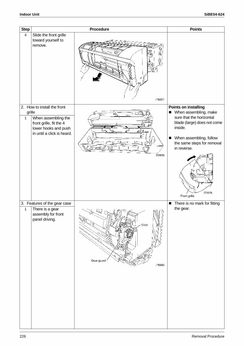
Indoor Unit SiBE04-624
226 Removal Procedure
4 Slide the front grille toward yourself to remove.
2. How to install the front grille
Points on installingWhen assembling, make sure that the horizontal blade (large) does not come inside.
When assembling, follow the same steps for removal in reverse.
1 When assembling the front grille, fit the 4 lower hooks and push in until a click is heard.
3. Features of the gear case There is no mark for fitting the gear.1 There is a gear
assembly for front panel driving.
Step Procedure Points
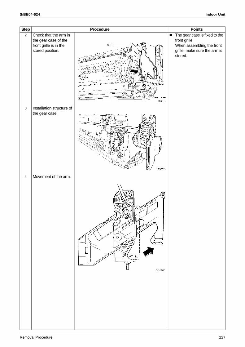
SiBE04-624 Indoor Unit
Removal Procedure 227
2 Check that the arm in the gear case of the front grille is in the stored position.
The gear case is fixed to the front grille.When assembling the front grille, make sure the arm is stored.
3 Installation structure of the gear case.
4 Movement of the arm.
Step Procedure Points
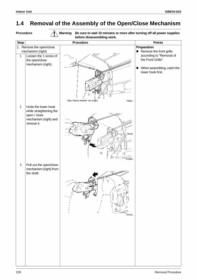
Indoor Unit SiBE04-624
228 Removal Procedure
1.4 Removal of the Assembly of the Open/Close Mechanism
Procedure Warning Be sure to wait 10 minutes or more after turning off all power supplies before disassembling work.
Step Procedure Points1. Remove the open/close
mechanism (right)Preparation
Remove the front grille according to "Removal of the Front Grille".
When assembling, catch the lower hook first.
1 Loosen the 1 screw of the open/close mechanism (right).
2 Undo the lower hook while straightening the open / close mechanism (right) and remove it.
3 Pull out the open/close mechanism (right) from the shaft.
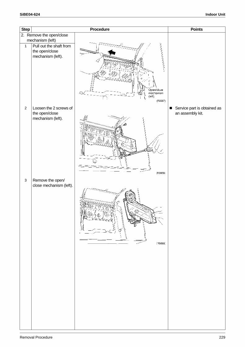
SiBE04-624 Indoor Unit
Removal Procedure 229
2. Remove the open/close mechanism (left)
1 Pull out the shaft from the open/close mechanism (left).
2 Loosen the 2 screws of the open/close mechanism (left).
Service part is obtained as an assembly kit.
3 Remove the open/close mechanism (left).
Step Procedure Points
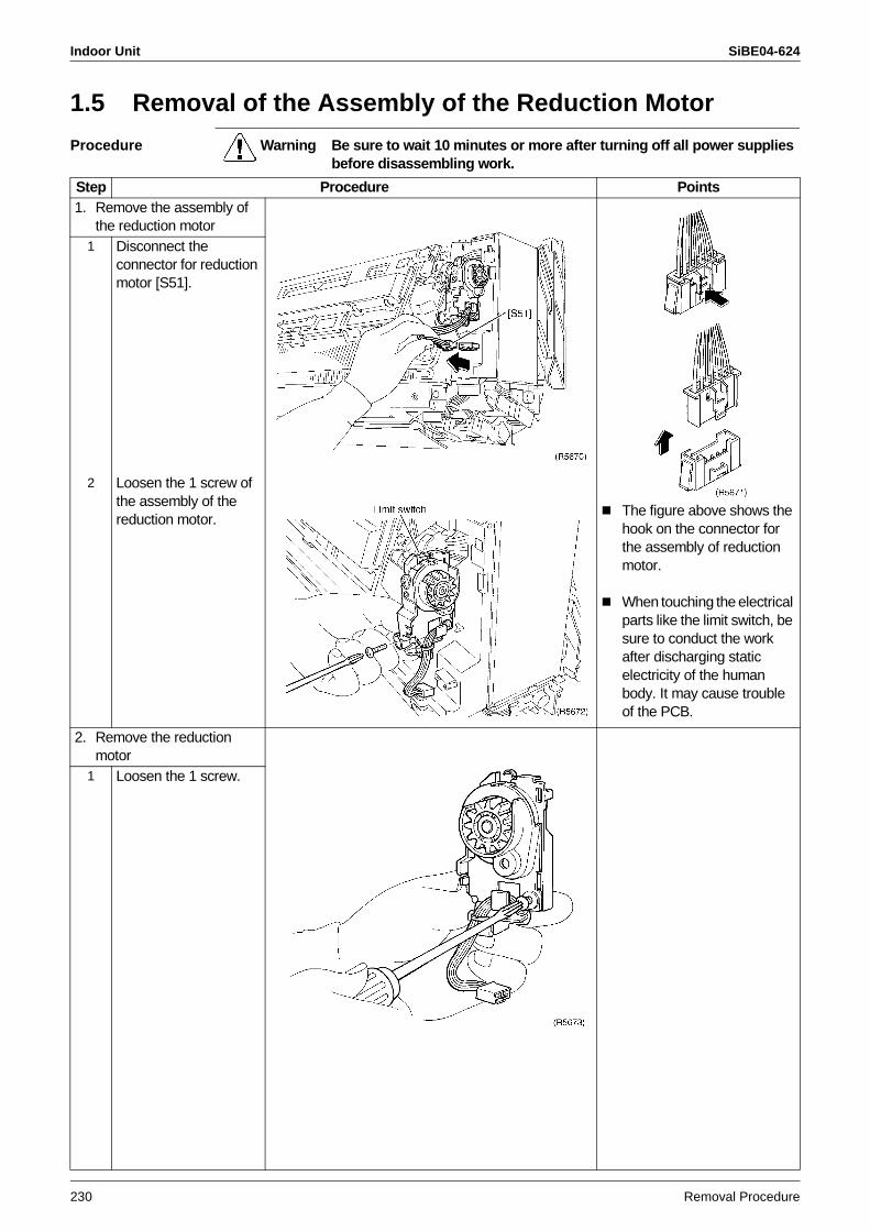
Indoor Unit SiBE04-624
230 Removal Procedure
1.5 Removal of the Assembly of the Reduction Motor
Procedure Warning Be sure to wait 10 minutes or more after turning off all power supplies before disassembling work.
Step Procedure Points1. Remove the assembly of
the reduction motor
The figure above shows the hook on the connector for the assembly of reduction motor.
When touching the electrical parts like the limit switch, be sure to conduct the work after discharging static electricity of the human body. It may cause trouble of the PCB.
1 Disconnect the connector for reduction motor [S51].
2 Loosen the 1 screw of the assembly of the reduction motor.
2. Remove the reduction motor
1 Loosen the 1 screw.
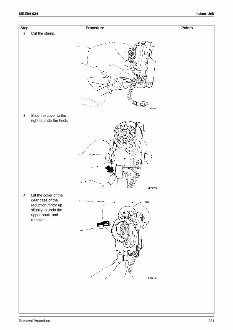
SiBE04-624 Indoor Unit
Removal Procedure 231
2 Cut the clamp.
3 Slide the cover to the right to undo the hook.
4 Lift the cover of the gear case of the reduction motor up slightly to undo the upper hook, and remove it.
Step Procedure Points
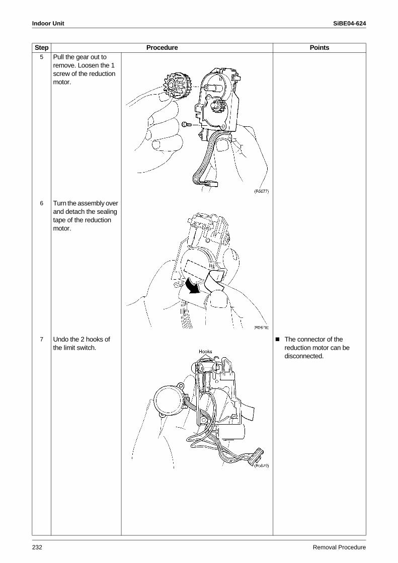
Indoor Unit SiBE04-624
232 Removal Procedure
5 Pull the gear out to remove. Loosen the 1 screw of the reduction motor.
6 Turn the assembly over and detach the sealing tape of the reduction motor.
7 Undo the 2 hooks of the limit switch.
The connector of the reduction motor can be disconnected.
Step Procedure Points
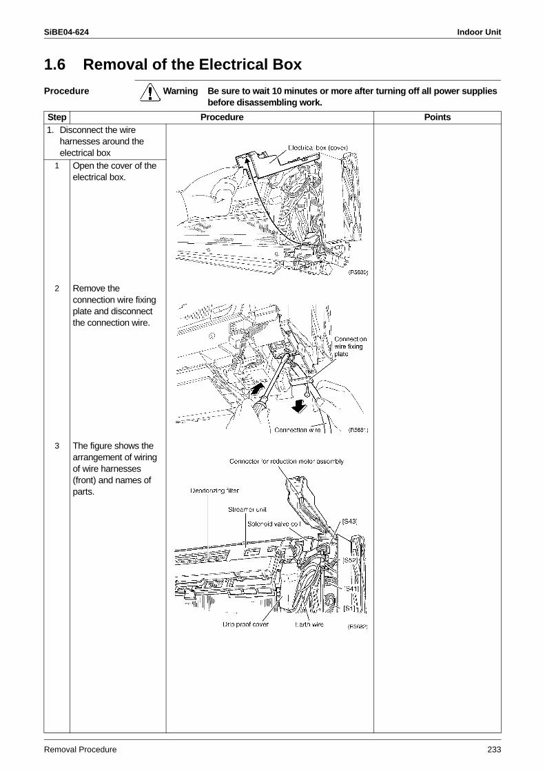
SiBE04-624 Indoor Unit
Removal Procedure 233
1.6 Removal of the Electrical Box
Procedure Warning Be sure to wait 10 minutes or more after turning off all power supplies before disassembling work.
Step Procedure Points1. Disconnect the wire
harnesses around the electrical box
1 Open the cover of the electrical box.
2 Remove the connection wire fixing plate and disconnect the connection wire.
3 The figure shows the arrangement of wiring of wire harnesses (front) and names of parts.
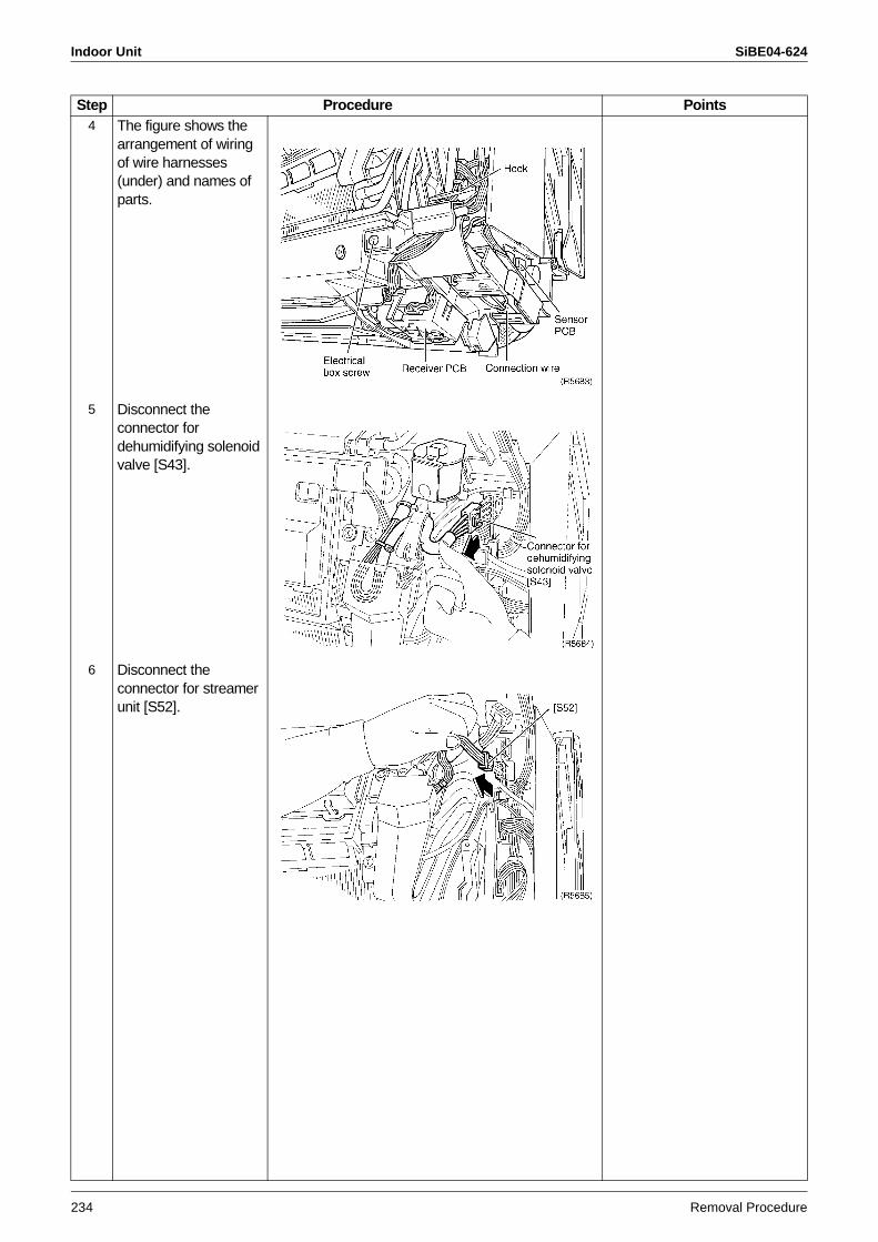
Indoor Unit SiBE04-624
234 Removal Procedure
4 The figure shows the arrangement of wiring of wire harnesses (under) and names of parts.
5 Disconnect the connector for dehumidifying solenoid valve [S43].
6 Disconnect the connector for streamer unit [S52].
Step Procedure Points
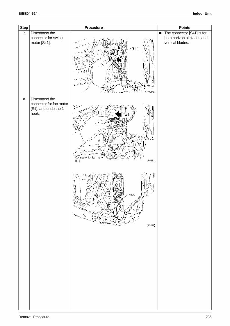
SiBE04-624 Indoor Unit
Removal Procedure 235
7 Disconnect the connector for swing motor [S41].
The connector [S41] is for both horizontal blades and vertical blades.
8 Disconnect the connector for fan motor [S1], and undo the 1 hook.
Step Procedure Points
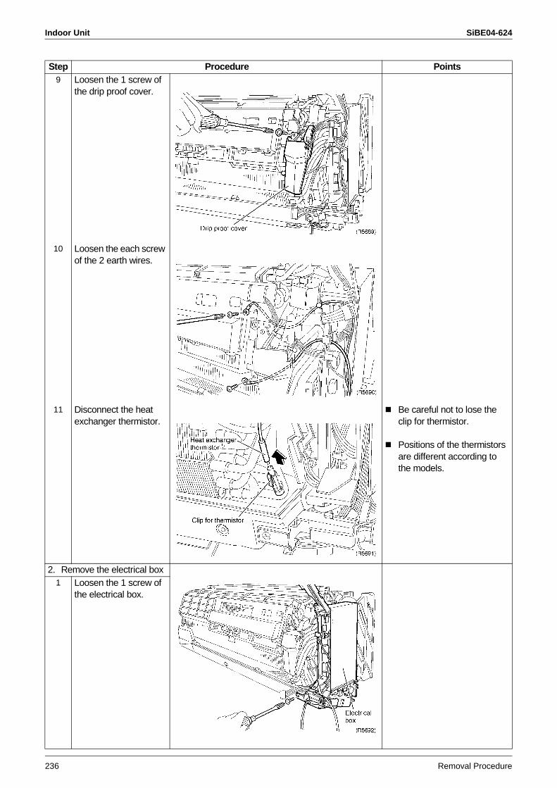
Indoor Unit SiBE04-624
236 Removal Procedure
9 Loosen the 1 screw of the drip proof cover.
10 Loosen the each screw of the 2 earth wires.
11 Disconnect the heat exchanger thermistor.
Be careful not to lose the clip for thermistor.
Positions of the thermistors are different according to the models.
2. Remove the electrical box1 Loosen the 1 screw of
the electrical box.
Step Procedure Points
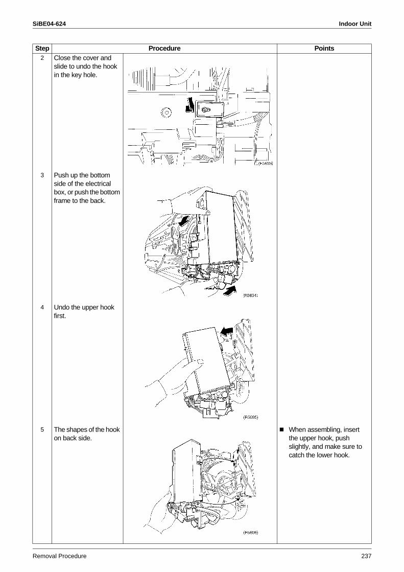
SiBE04-624 Indoor Unit
Removal Procedure 237
2 Close the cover and slide to undo the hook in the key hole.
3 Push up the bottom side of the electrical box, or push the bottom frame to the back.
4 Undo the upper hook first.
5 The shapes of the hook on back side.
When assembling, insert the upper hook, push slightly, and make sure to catch the lower hook.
Step Procedure Points
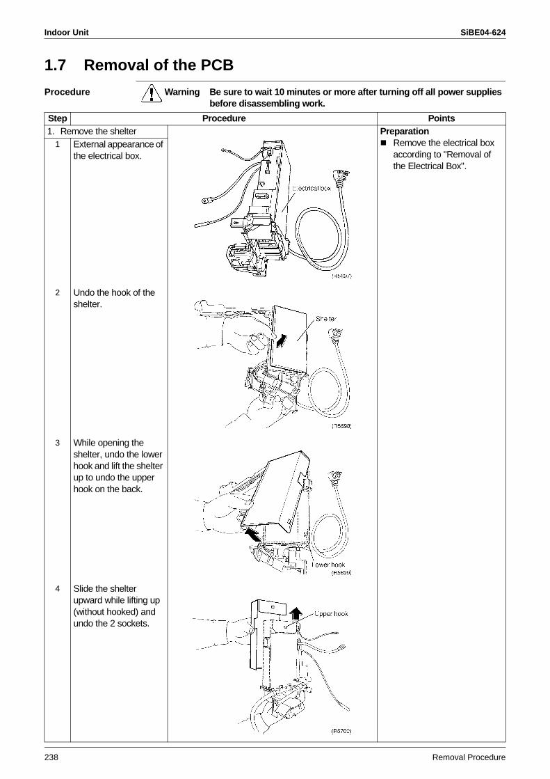
Indoor Unit SiBE04-624
238 Removal Procedure
1.7 Removal of the PCB
Procedure Warning Be sure to wait 10 minutes or more after turning off all power supplies before disassembling work.
Step Procedure Points1. Remove the shelter Preparation
Remove the electrical box according to "Removal of the Electrical Box".
1 External appearance of the electrical box.
2 Undo the hook of the shelter.
3 While opening the shelter, undo the lower hook and lift the shelter up to undo the upper hook on the back.
4 Slide the shelter upward while lifting up (without hooked) and undo the 2 sockets.
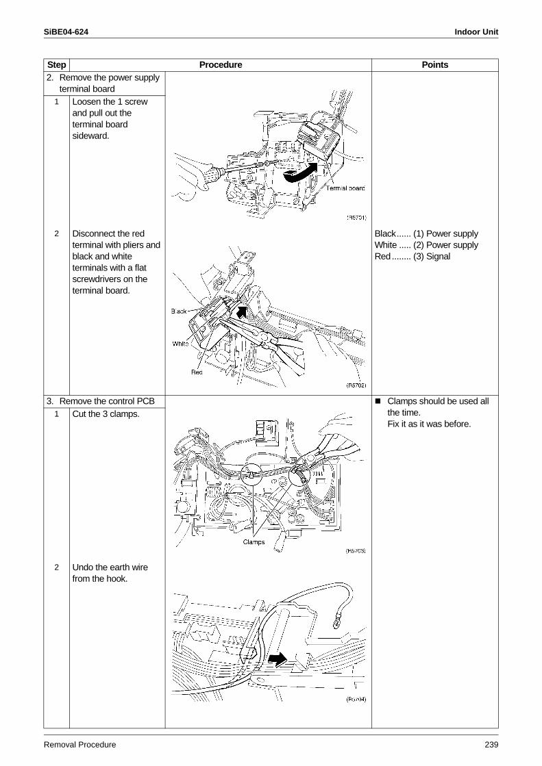
SiBE04-624 Indoor Unit
Removal Procedure 239
2. Remove the power supply terminal board
1 Loosen the 1 screw and pull out the terminal board sideward.
2 Disconnect the red terminal with pliers and black and white terminals with a flat screwdrivers on the terminal board.
Black...... (1) Power supplyWhite ..... (2) Power supplyRed........ (3) Signal
3. Remove the control PCB Clamps should be used all the time.Fix it as it was before.
1 Cut the 3 clamps.
2 Undo the earth wire from the hook.
Step Procedure Points
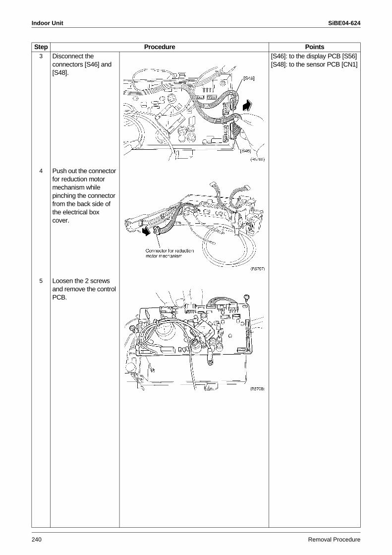
Indoor Unit SiBE04-624
240 Removal Procedure
3 Disconnect the connectors [S46] and [S48].
[S46]: to the display PCB [S56][S48]: to the sensor PCB [CN1]
4 Push out the connector for reduction motor mechanism while pinching the connector from the back side of the electrical box cover.
5 Loosen the 2 screws and remove the control PCB.
Step Procedure Points
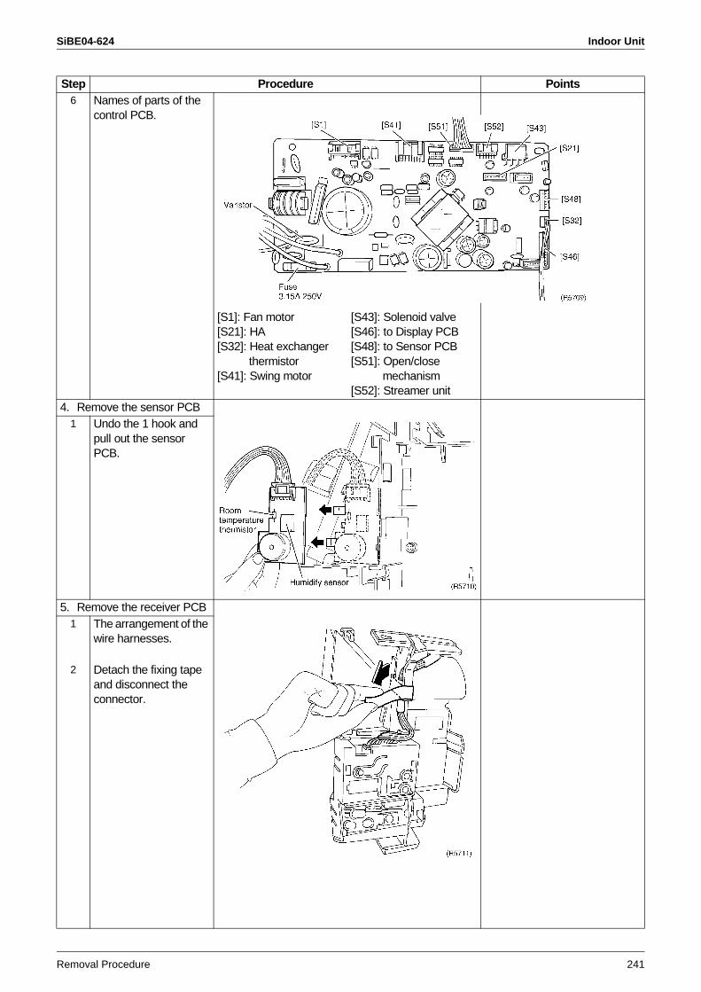
SiBE04-624 Indoor Unit
Removal Procedure 241
6 Names of parts of the control PCB.
[S1]: Fan motor [S43]: Solenoid valve[S21]: HA [S46]: to Display PCB[S32]: Heat exchanger [S48]: to Sensor PCB
thermistor [S51]: Open/close [S41]: Swing motor mechanism
[S52]: Streamer unit4. Remove the sensor PCB
1 Undo the 1 hook and pull out the sensor PCB.
5. Remove the receiver PCB1 The arrangement of the
wire harnesses.
2 Detach the fixing tape and disconnect the connector.
Step Procedure Points
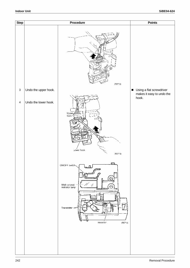
Indoor Unit SiBE04-624
242 Removal Procedure
3 Undo the upper hook. Using a flat screwdriver makes it easy to undo the hook.
4 Undo the lower hook.
Step Procedure Points
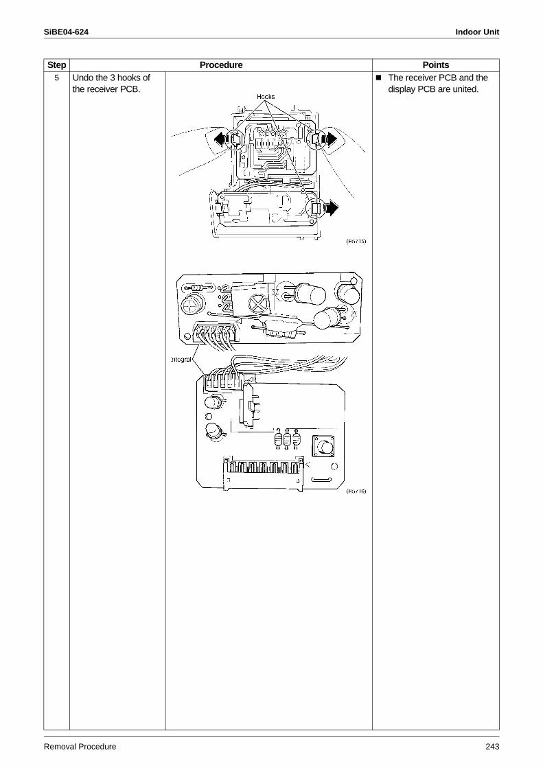
SiBE04-624 Indoor Unit
Removal Procedure 243
5 Undo the 3 hooks of the receiver PCB.
The receiver PCB and the display PCB are united.
Step Procedure Points
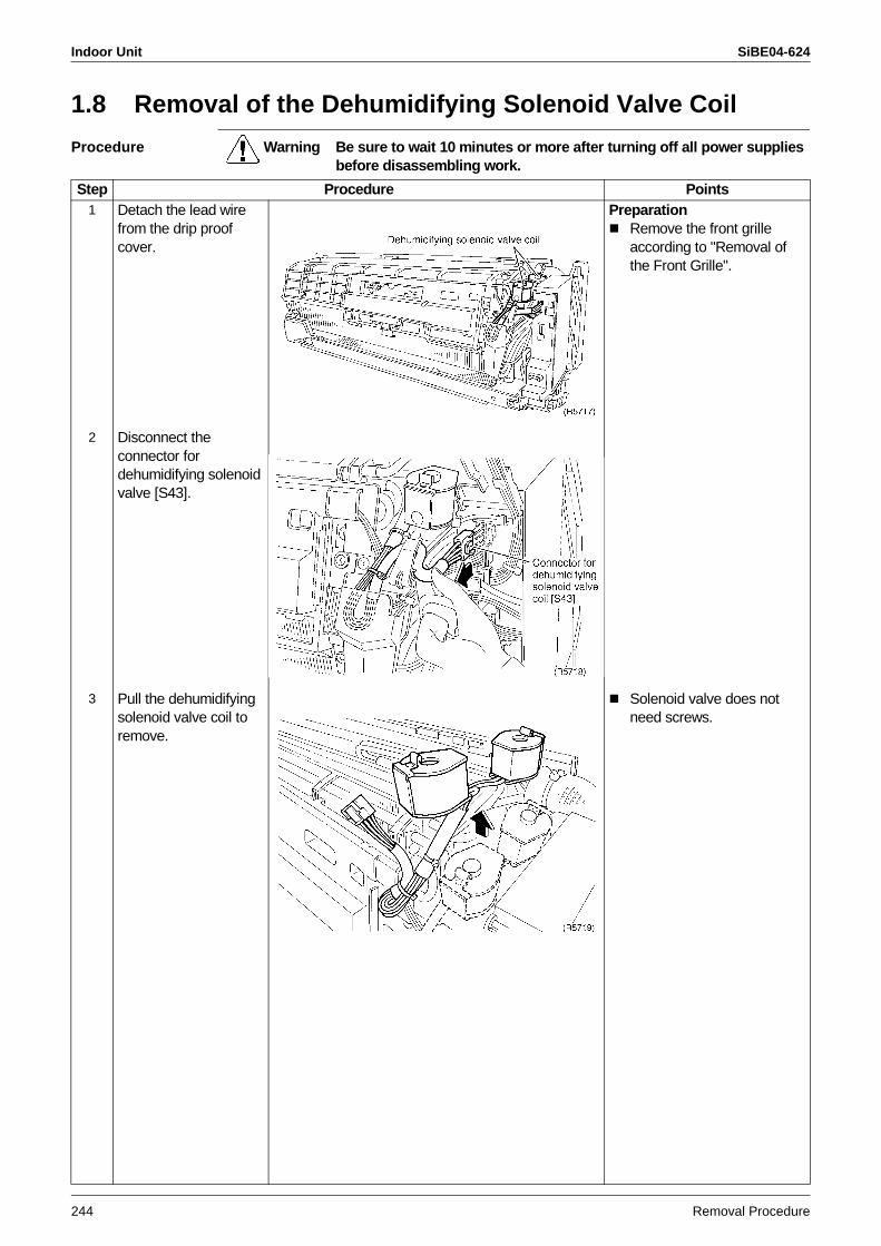
Indoor Unit SiBE04-624
244 Removal Procedure
1.8 Removal of the Dehumidifying Solenoid Valve Coil
Procedure Warning Be sure to wait 10 minutes or more after turning off all power supplies before disassembling work.
Step Procedure Points1 Detach the lead wire
from the drip proof cover.
PreparationRemove the front grille according to "Removal of the Front Grille".
2 Disconnect the connector for dehumidifying solenoid valve [S43].
3 Pull the dehumidifying solenoid valve coil to remove.
Solenoid valve does not need screws.
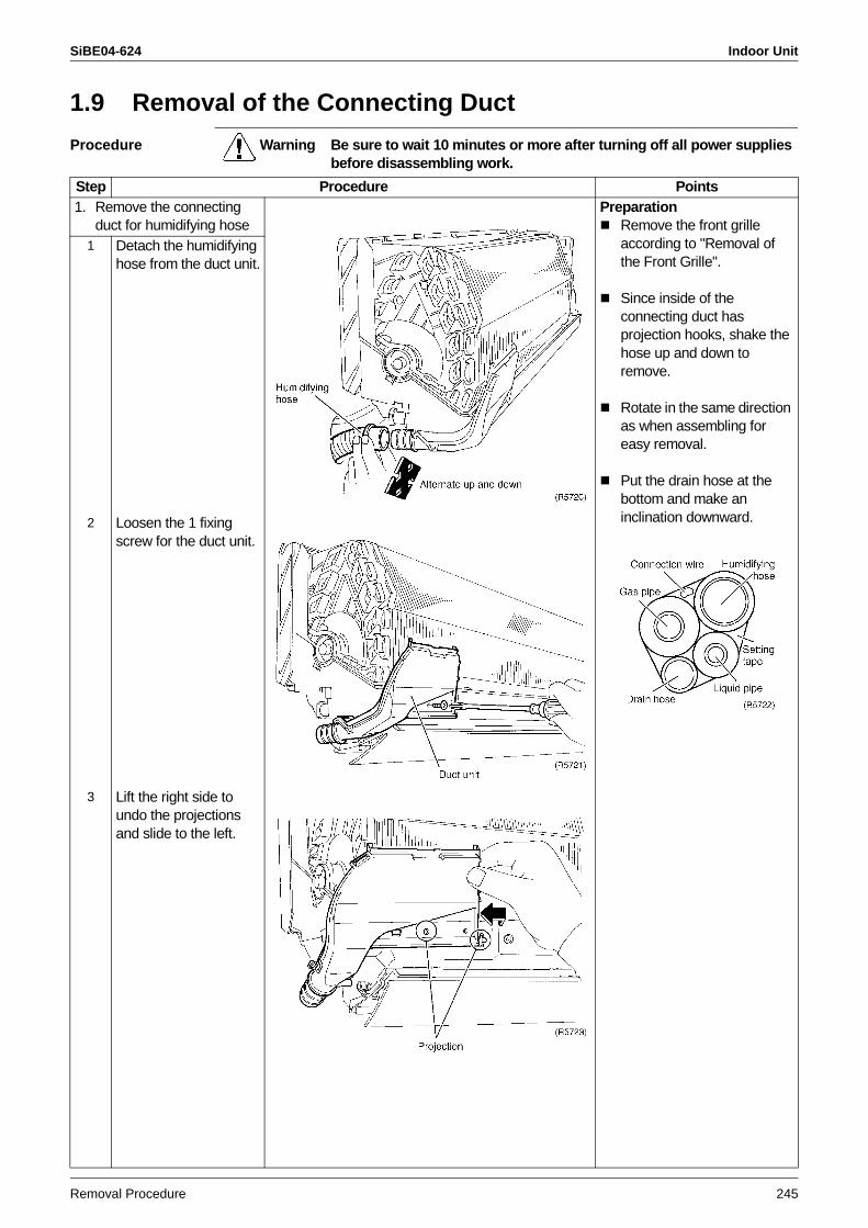
SiBE04-624 Indoor Unit
Removal Procedure 245
1.9 Removal of the Connecting Duct
Procedure Warning Be sure to wait 10 minutes or more after turning off all power supplies before disassembling work.
Step Procedure Points1. Remove the connecting
duct for humidifying hosePreparation
Remove the front grille according to "Removal of the Front Grille".
Since inside of the connecting duct has projection hooks, shake the hose up and down to remove.
Rotate in the same direction as when assembling for easy removal.
Put the drain hose at the bottom and make an inclination downward.
1 Detach the humidifying hose from the duct unit.
2 Loosen the 1 fixing screw for the duct unit.
3 Lift the right side to undo the projections and slide to the left.
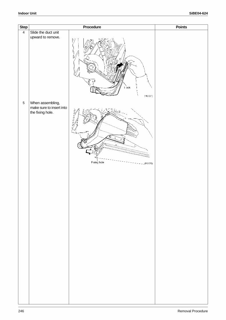
Indoor Unit SiBE04-624
246 Removal Procedure
4 Slide the duct unit upward to remove.
5 When assembling, make sure to insert into the fixing hole.
Step Procedure Points
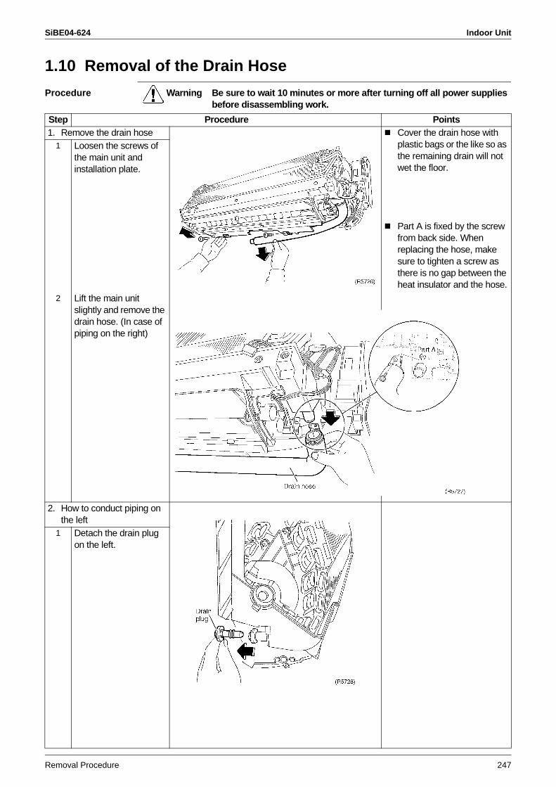
SiBE04-624 Indoor Unit
Removal Procedure 247
1.10 Removal of the Drain Hose
Procedure Warning Be sure to wait 10 minutes or more after turning off all power supplies before disassembling work.
Step Procedure Points1. Remove the drain hose Cover the drain hose with
plastic bags or the like so as the remaining drain will not wet the floor.
Part A is fixed by the screw from back side. When replacing the hose, make sure to tighten a screw as there is no gap between the heat insulator and the hose.
1 Loosen the screws of the main unit and installation plate.
2 Lift the main unit slightly and remove the drain hose. (In case of piping on the right)
2. How to conduct piping on the left
1 Detach the drain plug on the left.
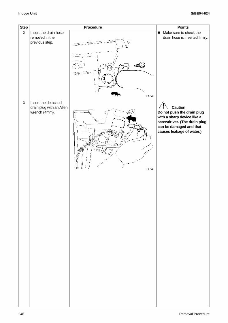
Indoor Unit SiBE04-624
248 Removal Procedure
2 Insert the drain hose removed in the previous step.
Make sure to check the drain hose is inserted firmly.
3 Insert the detached drain plug with an Allen wrench (4mm).
CautionDo not push the drain plug with a sharp device like a screwdriver. (The drain plug can be damaged and that causes leakage of water.)
Step Procedure Points
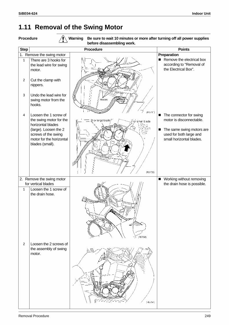
SiBE04-624 Indoor Unit
Removal Procedure 249
1.11 Removal of the Swing Motor
Procedure Warning Be sure to wait 10 minutes or more after turning off all power supplies before disassembling work.
Step Procedure Points1. Remove the swing motor Preparation
Remove the electrical box according to "Removal of the Electrical Box".
1 There are 3 hooks for the lead wire for swing motor.
2 Cut the clamp with nippers.
3 Undo the lead wire for swing motor from the hooks.
4 Loosen the 1 screw of the swing motor for the horizontal blades (large). Loosen the 2 screws of the swing motor for the horizontal blades (small).
The connector for swing motor is disconnectable.
The same swing motors are used for both large and small horizontal blades.
2. Remove the swing motor for vertical blades
Working without removing the drain hose is possible.
1 Loosen the 1 screw of the drain hose.
2 Loosen the 2 screws of the assembly of swing motor.
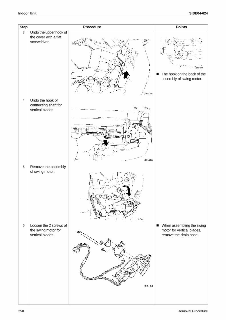
Indoor Unit SiBE04-624
250 Removal Procedure
3 Undo the upper hook of the cover with a flat screwdriver.
The hook on the back of the assembly of swing motor.
4 Undo the hook of connecting shaft for vertical blades.
5 Remove the assembly of swing motor.
6 Loosen the 2 screws of the swing motor for vertical blades.
When assembling the swing motor for vertical blades, remove the drain hose.
Step Procedure Points
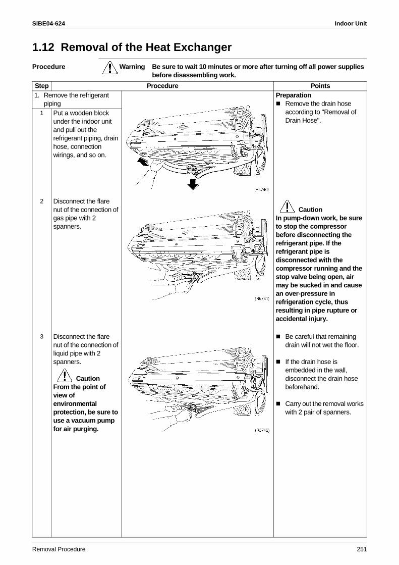
SiBE04-624 Indoor Unit
Removal Procedure 251
1.12 Removal of the Heat Exchanger
Procedure Warning Be sure to wait 10 minutes or more after turning off all power supplies before disassembling work.
Step Procedure Points1. Remove the refrigerant
pipingPreparation
Remove the drain hose according to "Removal of Drain Hose".
1 Put a wooden block under the indoor unit and pull out the refrigerant piping, drain hose, connection wirings, and so on.
2 Disconnect the flare nut of the connection of gas pipe with 2 spanners.
CautionIn pump-down work, be sure to stop the compressor before disconnecting the refrigerant pipe. If the refrigerant pipe is disconnected with the compressor running and the stop valve being open, air may be sucked in and cause an over-pressure in refrigeration cycle, thus resulting in pipe rupture or accidental injury.
3 Disconnect the flare nut of the connection of liquid pipe with 2 spanners.
CautionFrom the point of view of environmental protection, be sure to use a vacuum pump for air purging.
Be careful that remaining drain will not wet the floor.
If the drain hose is embedded in the wall, disconnect the drain hose beforehand.
Carry out the removal works with 2 pair of spanners.
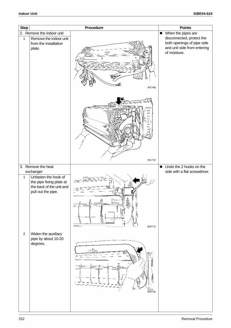
Indoor Unit SiBE04-624
252 Removal Procedure
2. Remove the indoor unit When the pipes are disconnected, protect the both openings of pipe side and unit side from entering of moisture.
1 Remove the indoor unit from the installation plate.
3. Remove the heat exchanger
Undo the 2 hooks on the side with a flat screwdriver.
1 Unfasten the hook of the pipe fixing plate at the back of the unit and pull out the pipe.
2 Widen the auxiliary pipe by about 10-20 degrees.
Step Procedure Points
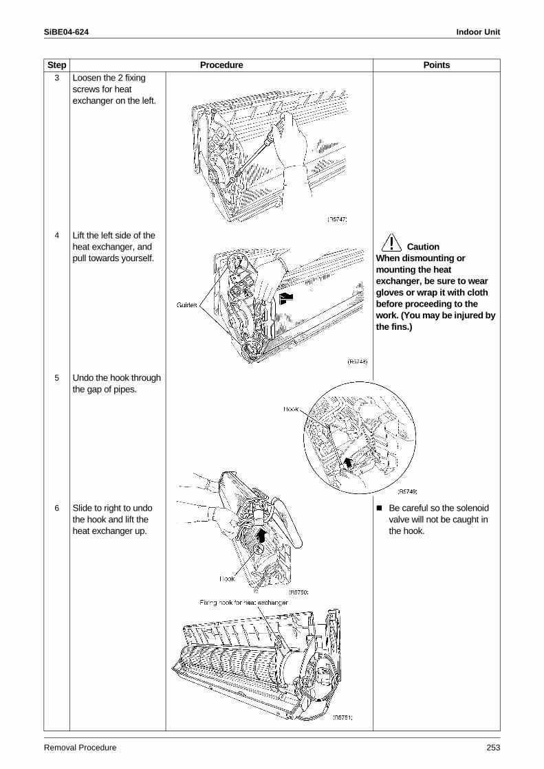
SiBE04-624 Indoor Unit
Removal Procedure 253
3 Loosen the 2 fixing screws for heat exchanger on the left.
4 Lift the left side of the heat exchanger, and pull towards yourself.
Caution
When dismounting or mounting the heat exchanger, be sure to wear gloves or wrap it with cloth before proceeding to the work. (You may be injured by the fins.)
5 Undo the hook through the gap of pipes.
6 Slide to right to undo the hook and lift the heat exchanger up.
Be careful so the solenoid valve will not be caught in the hook.
Step Procedure Points
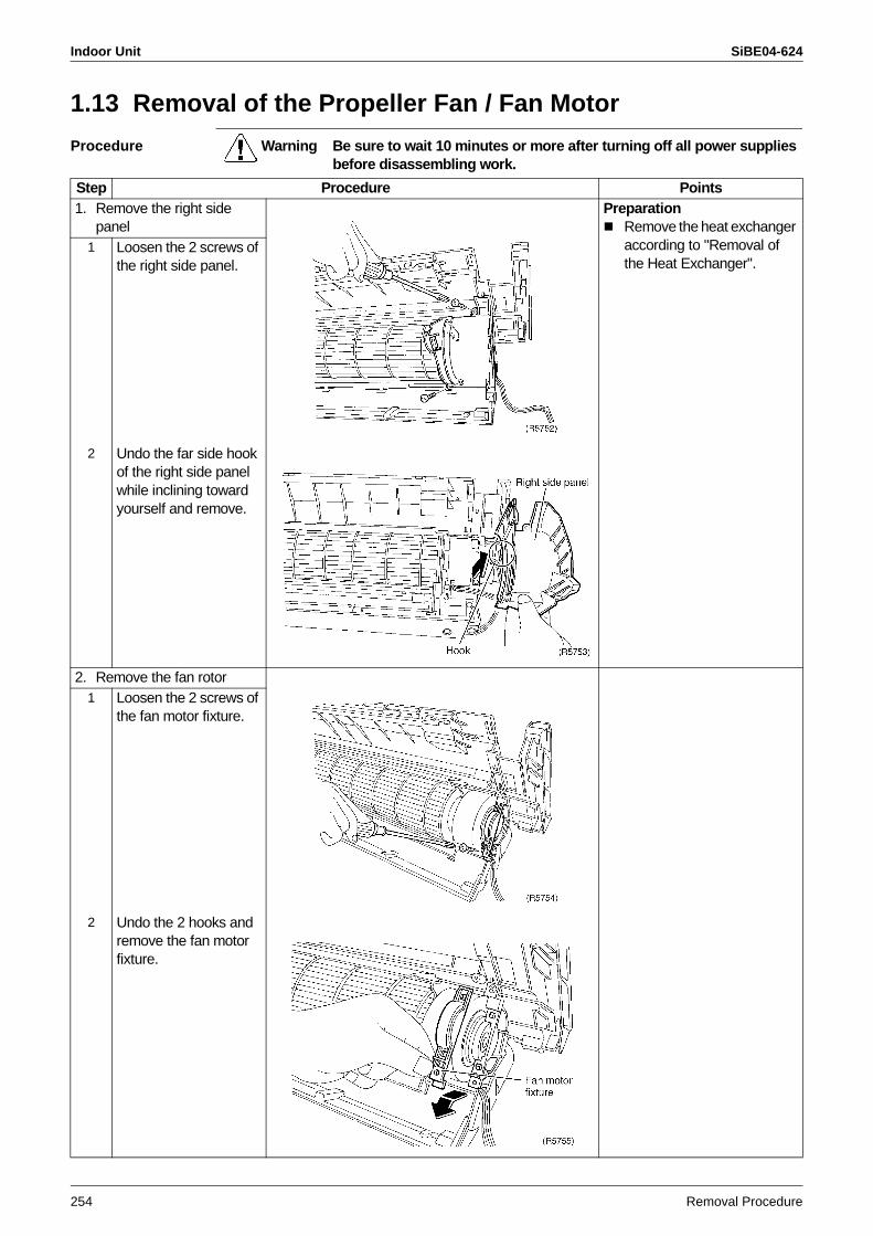
Indoor Unit SiBE04-624
254 Removal Procedure
1.13 Removal of the Propeller Fan / Fan Motor
Procedure Warning Be sure to wait 10 minutes or more after turning off all power supplies before disassembling work.
Step Procedure Points1. Remove the right side
panelPreparation
Remove the heat exchanger according to "Removal of the Heat Exchanger".
1 Loosen the 2 screws of the right side panel.
2 Undo the far side hook of the right side panel while inclining toward yourself and remove.
2. Remove the fan rotor1 Loosen the 2 screws of
the fan motor fixture.
2 Undo the 2 hooks and remove the fan motor fixture.
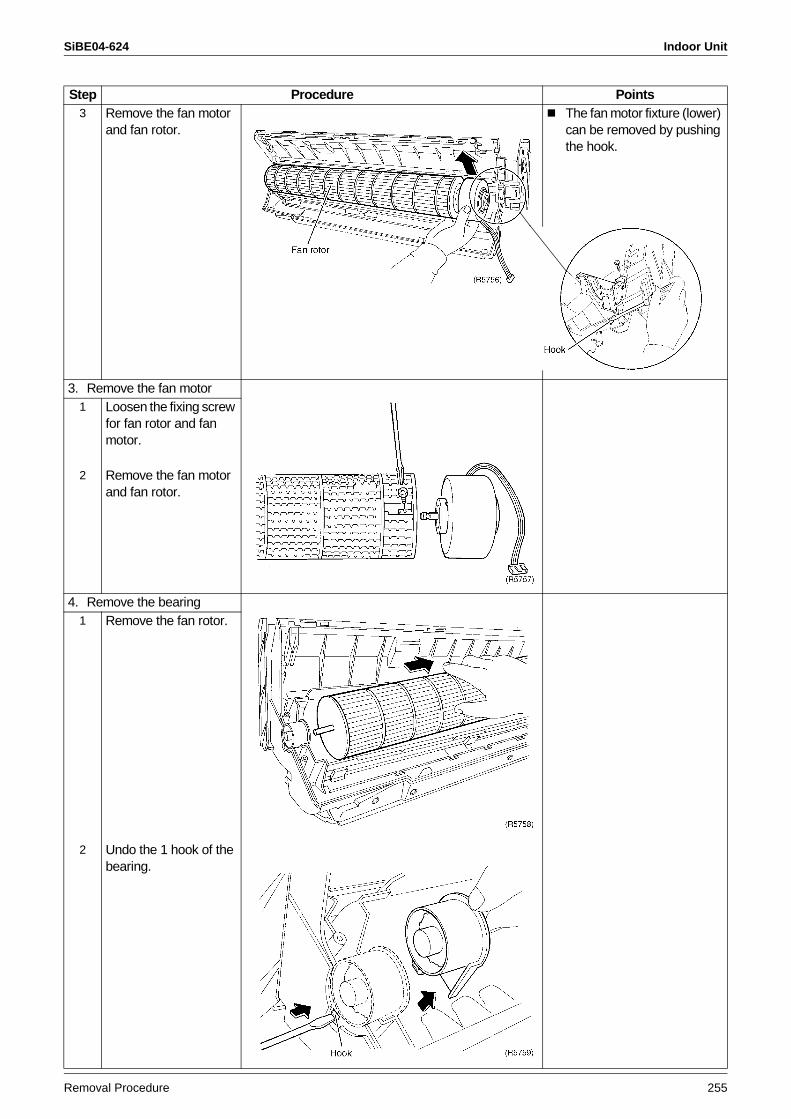
SiBE04-624 Indoor Unit
Removal Procedure 255
3 Remove the fan motor and fan rotor.
The fan motor fixture (lower) can be removed by pushing the hook.
3. Remove the fan motor1 Loosen the fixing screw
for fan rotor and fan motor.
2 Remove the fan motor and fan rotor.
4. Remove the bearing1 Remove the fan rotor.
2 Undo the 1 hook of the bearing.
Step Procedure Points
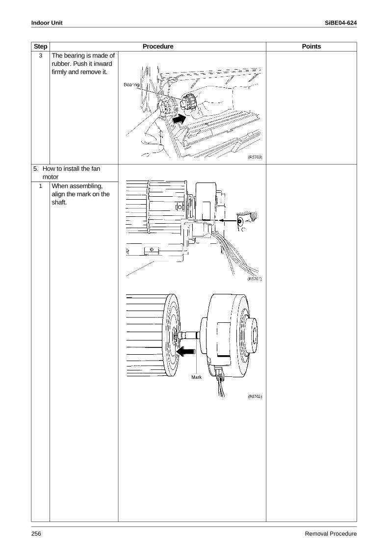
Indoor Unit SiBE04-624
256 Removal Procedure
3 The bearing is made of rubber. Push it inward firmly and remove it.
5. How to install the fan motor
1 When assembling, align the mark on the shaft.
Step Procedure Points
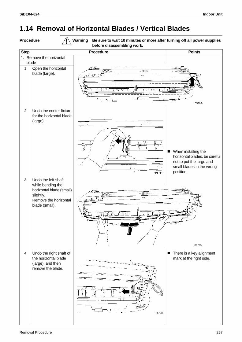
SiBE04-624 Indoor Unit
Removal Procedure 257
1.14 Removal of Horizontal Blades / Vertical Blades
Procedure Warning Be sure to wait 10 minutes or more after turning off all power supplies before disassembling work.
Step Procedure Points1. Remove the horizontal
blade1 Open the horizontal
blade (large).
2 Undo the center fixture for the horizontal blade (large).
When installing the horizontal blades, be careful not to put the large and small blades in the wrong position.
3 Undo the left shaft while bending the horizontal blade (small) slightly.Remove the horizontal blade (small).
4 Undo the right shaft of the horizontal blade (large), and then remove the blade.
There is a key alignment mark at the right side.
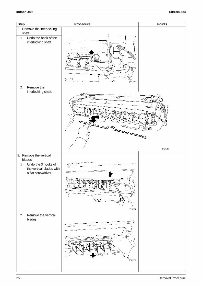
Indoor Unit SiBE04-624
258 Removal Procedure
2. Remove the interlocking shaft
1 Undo the hook of the interlocking shaft.
2 Remove the interlocking shaft.
3. Remove the vertical blades
1 Undo the 3 hooks of the vertical blades with a flat screwdriver.
2 Remove the vertical blades.
Step Procedure Points
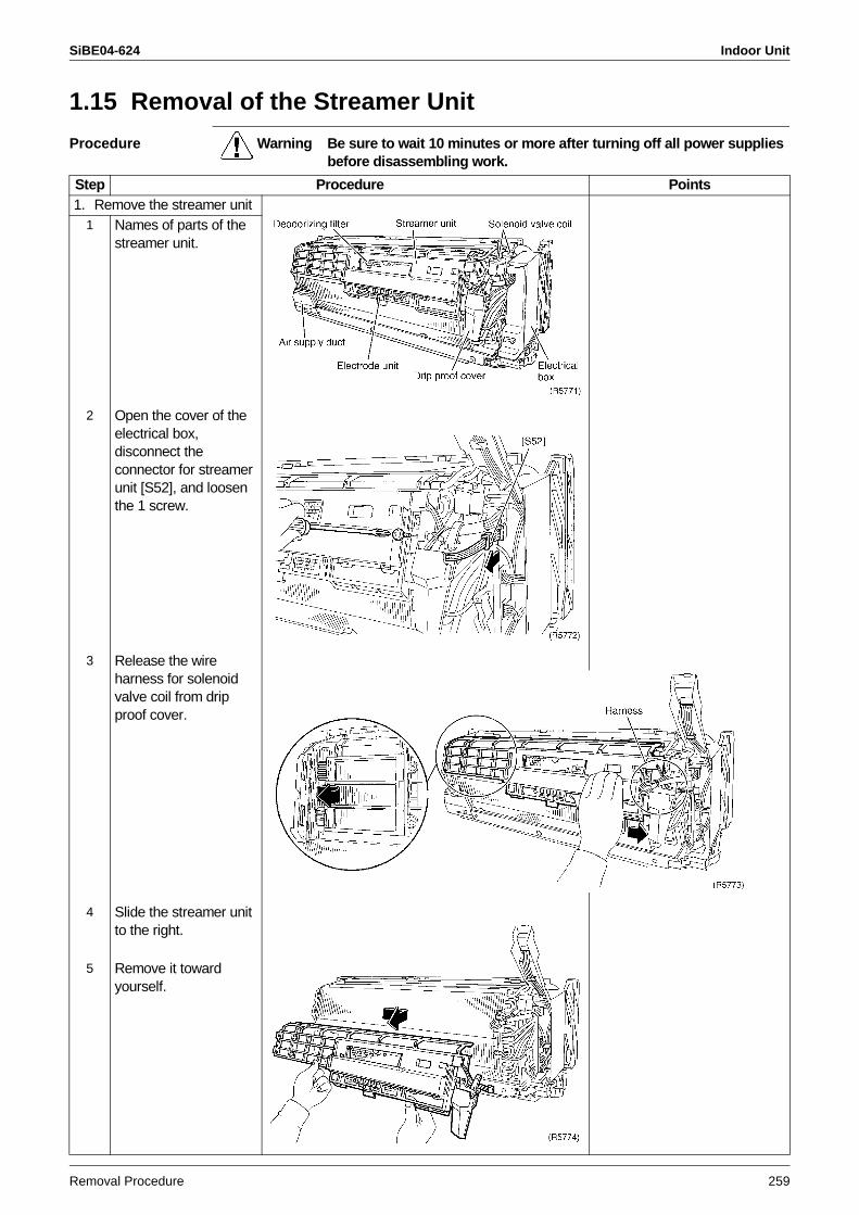
SiBE04-624 Indoor Unit
Removal Procedure 259
1.15 Removal of the Streamer Unit
Procedure Warning Be sure to wait 10 minutes or more after turning off all power supplies before disassembling work.
Step Procedure Points1. Remove the streamer unit
1 Names of parts of the streamer unit.
2 Open the cover of the electrical box, disconnect the connector for streamer unit [S52], and loosen the 1 screw.
3 Release the wire harness for solenoid valve coil from drip proof cover.
4 Slide the streamer unit to the right.
5 Remove it toward yourself.
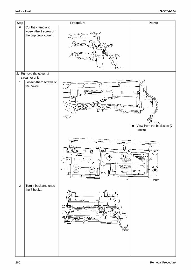
Indoor Unit SiBE04-624
260 Removal Procedure
6 Cut the clamp and loosen the 1 screw of the drip proof cover.
2. Remove the cover of streamer unit
View from the back side (7 hooks)
1 Loosen the 2 screws of the cover.
2 Turn it back and undo the 7 hooks.
Step Procedure Points
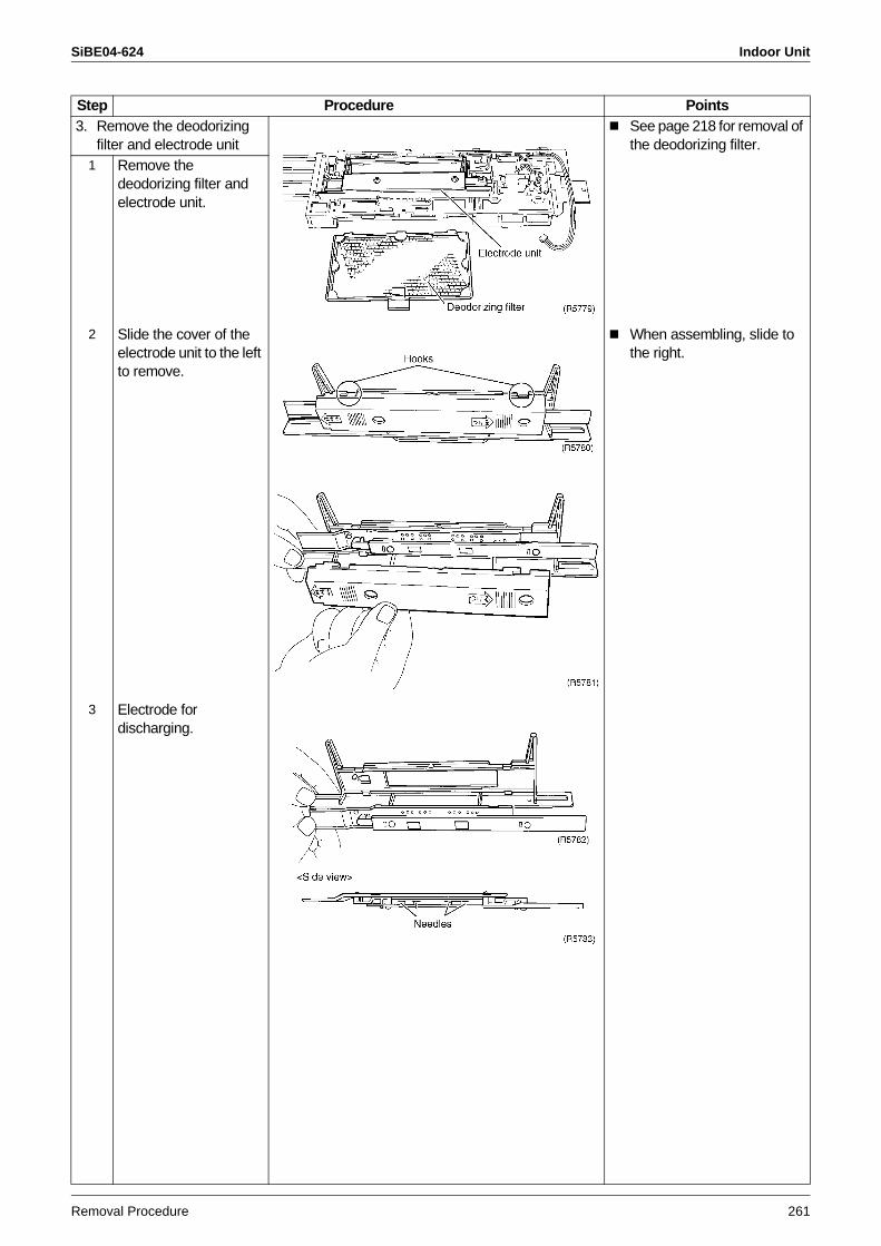
SiBE04-624 Indoor Unit
Removal Procedure 261
3. Remove the deodorizing filter and electrode unit
See page 218 for removal of the deodorizing filter.
1 Remove the deodorizing filter and electrode unit.
2 Slide the cover of the electrode unit to the left to remove.
When assembling, slide to the right.
3 Electrode for discharging.
Step Procedure Points
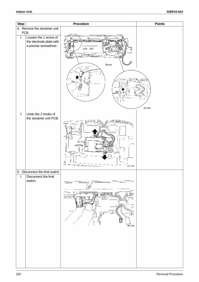
Indoor Unit SiBE04-624
262 Removal Procedure
4. Remove the streamer unit PCB
1 Loosen the 1 screw of the electrode plate with a precise screwdriver.
2 Undo the 2 hooks of the streamer unit PCB.
5. Disconnect the limit switch1 Disconnect the limit
switch.
Step Procedure Points
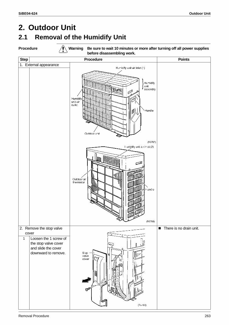
SiBE04-624 Outdoor Unit
Removal Procedure 263
2. Outdoor Unit2.1 Removal of the Humidify Unit
Procedure Warning Be sure to wait 10 minutes or more after turning off all power supplies before disassembling work.
Step Procedure Points1. External appearance
2. Remove the stop valve cover
There is no drain unit.
1 Loosen the 1 screw of the stop valve cover and slide the cover downward to remove.
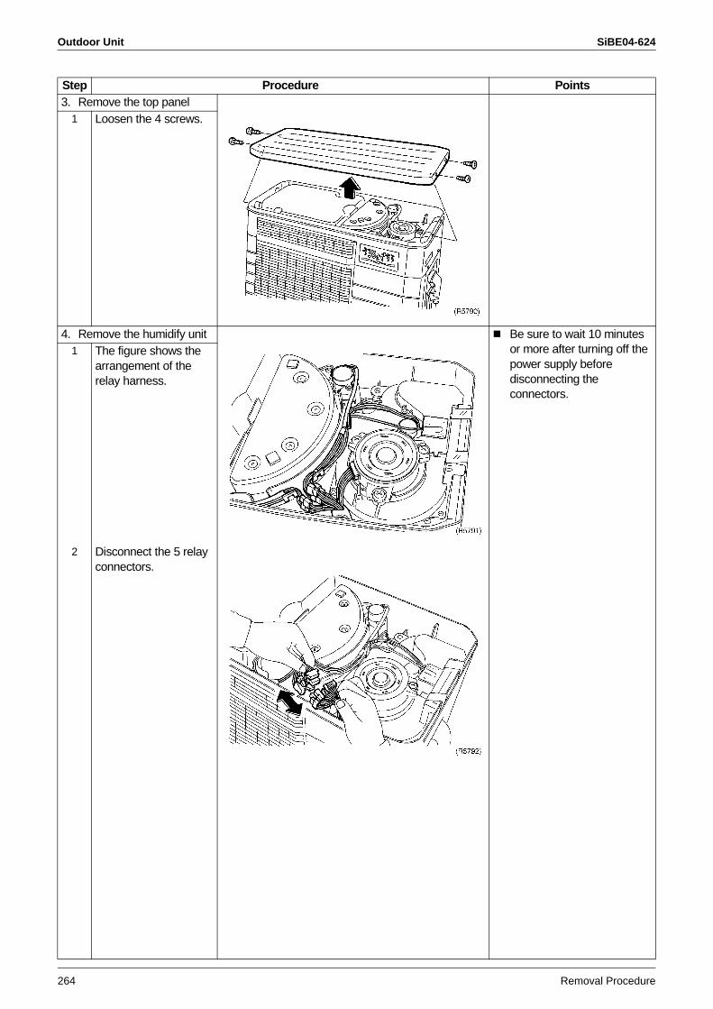
Outdoor Unit SiBE04-624
264 Removal Procedure
3. Remove the top panel1 Loosen the 4 screws.
4. Remove the humidify unit Be sure to wait 10 minutes or more after turning off the power supply before disconnecting the connectors.
1 The figure shows the arrangement of the relay harness.
2 Disconnect the 5 relay connectors.
Step Procedure Points
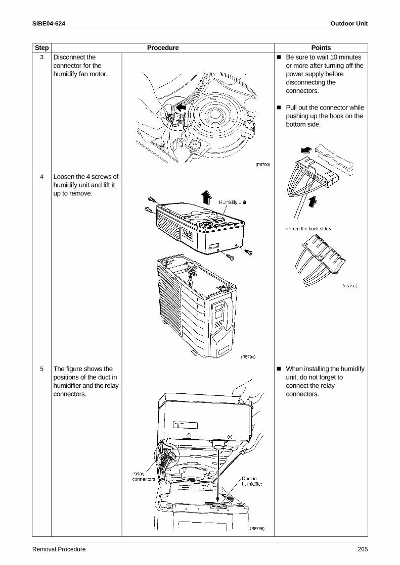
SiBE04-624 Outdoor Unit
Removal Procedure 265
3 Disconnect the connector for the humidify fan motor.
Be sure to wait 10 minutes or more after turning off the power supply before disconnecting the connectors.
Pull out the connector while pushing up the hook on the bottom side.
4 Loosen the 4 screws of humidify unit and lift it up to remove.
5 The figure shows the positions of the duct in humidifier and the relay connectors.
When installing the humidify unit, do not forget to connect the relay connectors.
Step Procedure Points
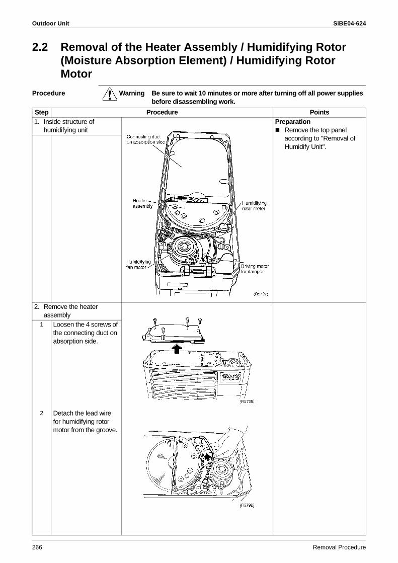
Outdoor Unit SiBE04-624
266 Removal Procedure
2.2 Removal of the Heater Assembly / Humidifying Rotor (Moisture Absorption Element) / Humidifying Rotor Motor
Procedure Warning Be sure to wait 10 minutes or more after turning off all power supplies before disassembling work.
Step Procedure Points1. Inside structure of
humidifying unitPreparation
Remove the top panel according to "Removal of Humidify Unit".
2. Remove the heater assembly
1 Loosen the 4 screws of the connecting duct on absorption side.
2 Detach the lead wire for humidifying rotor motor from the groove.
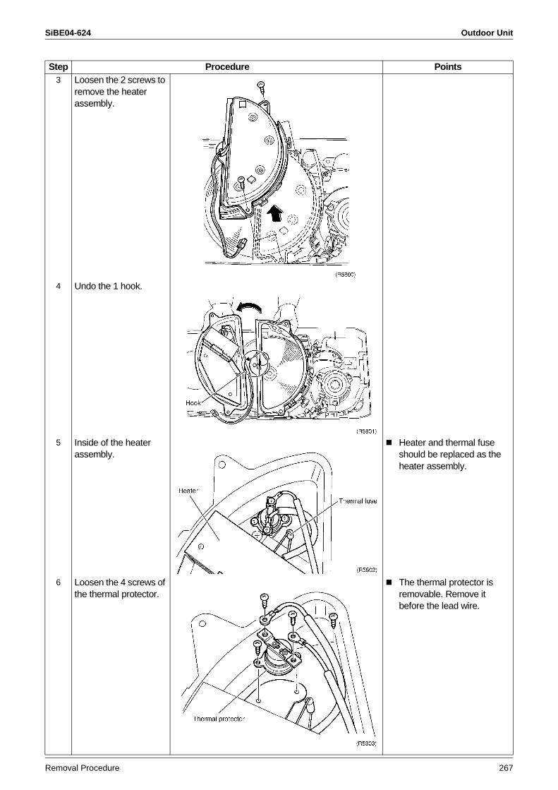
SiBE04-624 Outdoor Unit
Removal Procedure 267
3 Loosen the 2 screws to remove the heater assembly.
4 Undo the 1 hook.
5 Inside of the heater assembly.
Heater and thermal fuse should be replaced as the heater assembly.
6 Loosen the 4 screws of the thermal protector.
The thermal protector is removable. Remove it before the lead wire.
Step Procedure Points
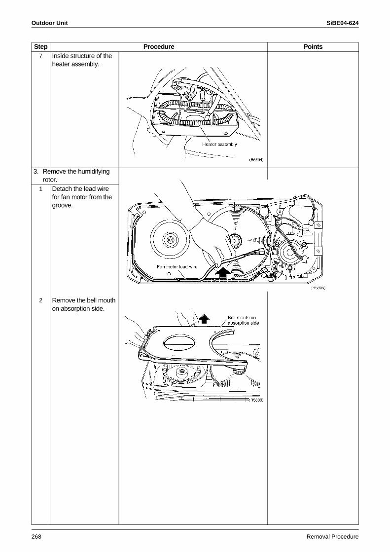
Outdoor Unit SiBE04-624
268 Removal Procedure
7 Inside structure of the heater assembly.
3. Remove the humidifying rotor.
1 Detach the lead wire for fan motor from the groove.
2 Remove the bell mouth on absorption side.
Step Procedure Points
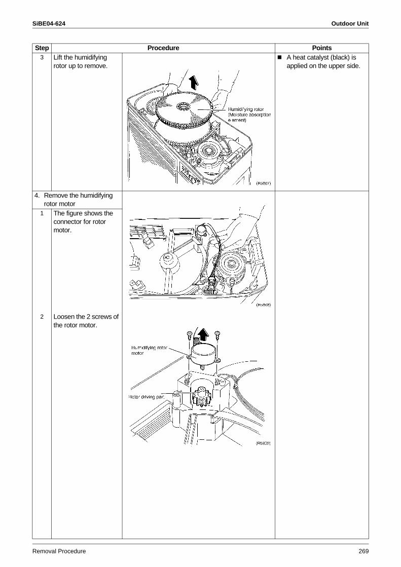
SiBE04-624 Outdoor Unit
Removal Procedure 269
3 Lift the humidifying rotor up to remove.
A heat catalyst (black) is applied on the upper side.
4. Remove the humidifying rotor motor
1 The figure shows the connector for rotor motor.
2 Loosen the 2 screws of the rotor motor.
Step Procedure Points
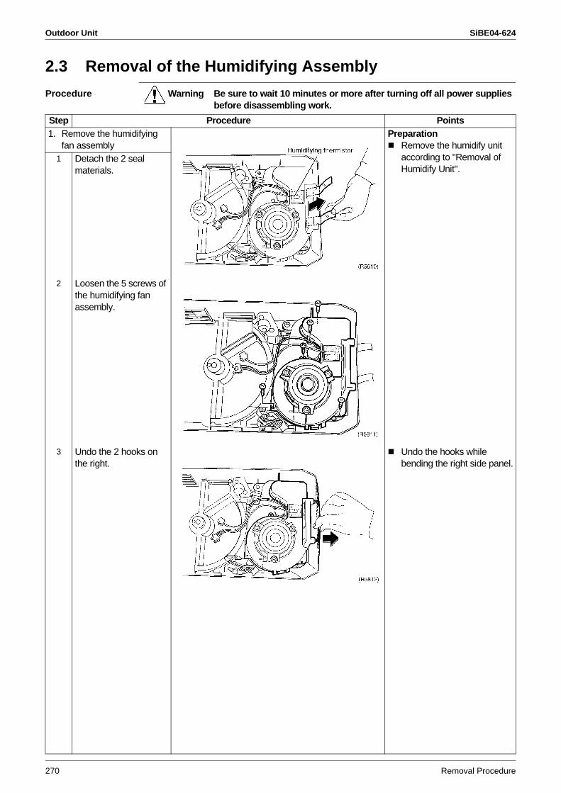
Outdoor Unit SiBE04-624
270 Removal Procedure
2.3 Removal of the Humidifying Assembly
Procedure Warning Be sure to wait 10 minutes or more after turning off all power supplies before disassembling work.
Step Procedure Points1. Remove the humidifying
fan assemblyPreparation
Remove the humidify unit according to "Removal of Humidify Unit".
1 Detach the 2 seal materials.
2 Loosen the 5 screws of the humidifying fan assembly.
3 Undo the 2 hooks on the right.
Undo the hooks while bending the right side panel.
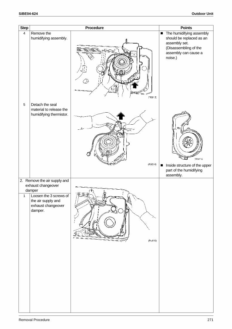
SiBE04-624 Outdoor Unit
Removal Procedure 271
4 Remove the humidifying assembly.
The humidifying assembly should be replaced as an assembly set. (Disassembling of the assembly can cause a noise.)
5 Detach the seal material to release the humidifying thermistor.
Inside structure of the upper part of the humidifying assembly.
2. Remove the air supply and exhaust changeover damper
1 Loosen the 3 screws of the air supply and exhaust changeover damper.
Step Procedure Points
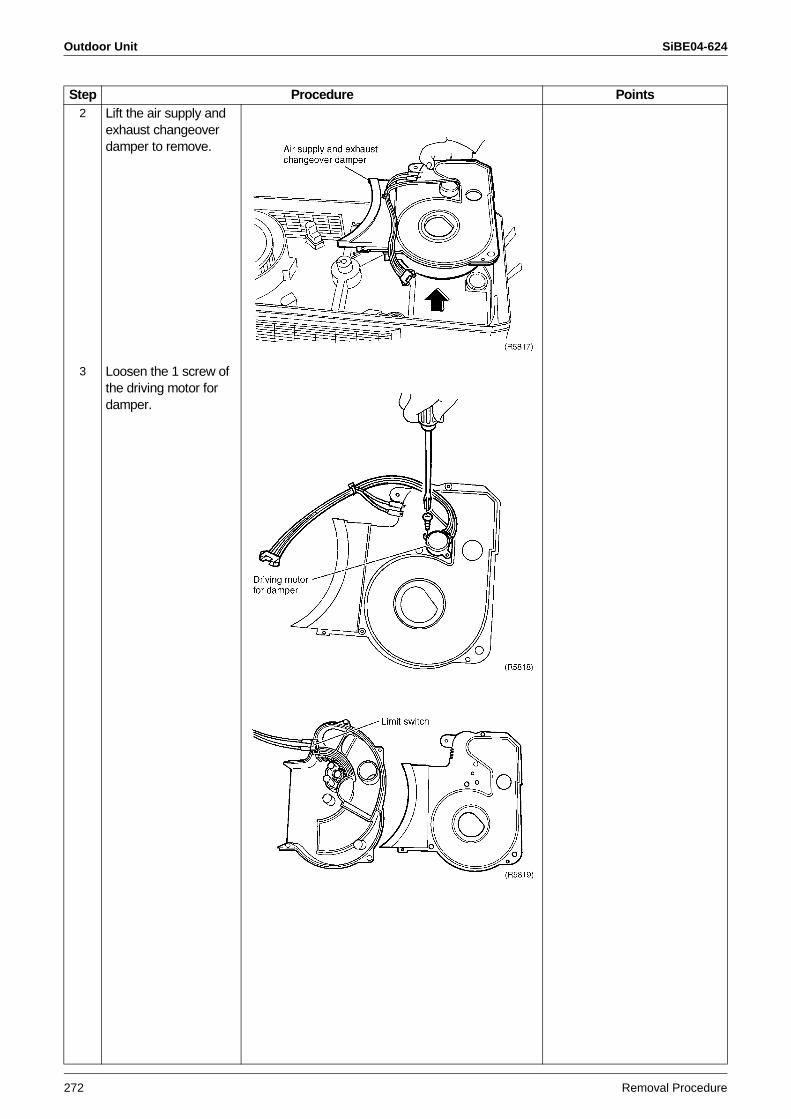
Outdoor Unit SiBE04-624
272 Removal Procedure
2 Lift the air supply and exhaust changeover damper to remove.
3 Loosen the 1 screw of the driving motor for damper.
Step Procedure Points
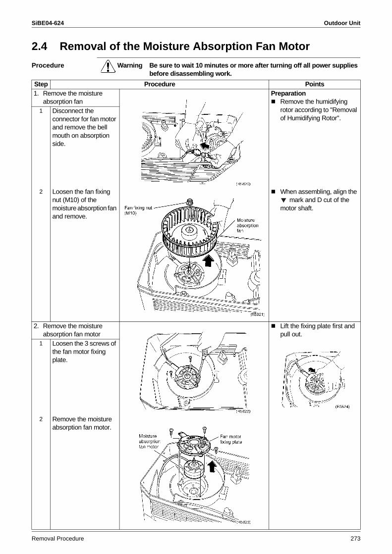
SiBE04-624 Outdoor Unit
Removal Procedure 273
2.4 Removal of the Moisture Absorption Fan Motor
Procedure Warning Be sure to wait 10 minutes or more after turning off all power supplies before disassembling work.
Step Procedure Points1. Remove the moisture
absorption fanPreparation
Remove the humidifying rotor according to "Removal of Humidifying Rotor".
1 Disconnect the connector for fan motor and remove the bell mouth on absorption side.
2 Loosen the fan fixing nut (M10) of the moisture absorption fan and remove.
When assembling, align the mark and D cut of the
motor shaft.
2. Remove the moisture absorption fan motor
Lift the fixing plate first and pull out.
1 Loosen the 3 screws of the fan motor fixing plate.
2 Remove the moisture absorption fan motor.
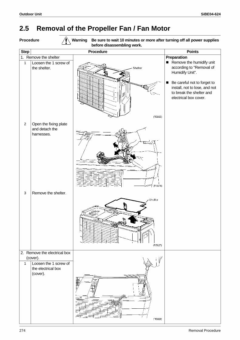
Outdoor Unit SiBE04-624
274 Removal Procedure
2.5 Removal of the Propeller Fan / Fan Motor
Procedure Warning Be sure to wait 10 minutes or more after turning off all power supplies before disassembling work.
Step Procedure Points1. Remove the shelter Preparation
Remove the humidify unit according to "Removal of Humidify Unit".
Be careful not to forget to install, not to lose, and not to break the shelter and electrical box cover.
1 Loosen the 1 screw of the shelter.
2 Open the fixing plate and detach the harnesses.
3 Remove the shelter.
2. Remove the electrical box (cover).
1 Loosen the 1 screw of the electrical box (cover).
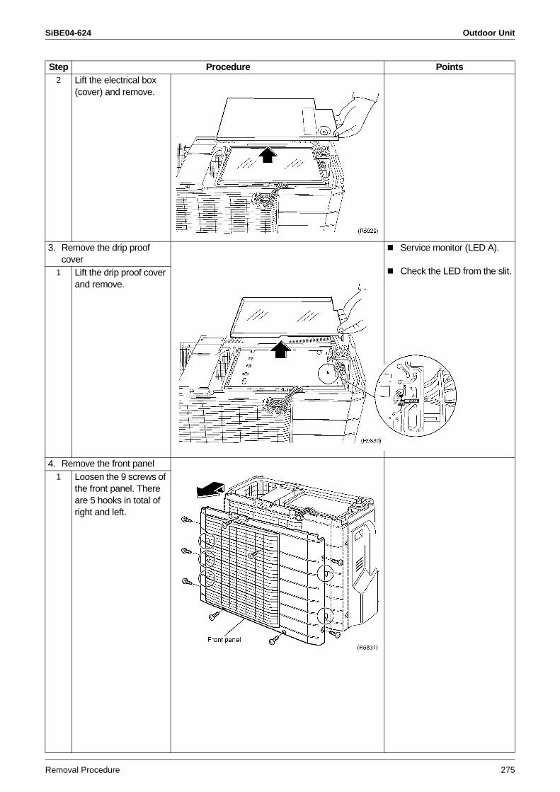
SiBE04-624 Outdoor Unit
Removal Procedure 275
2 Lift the electrical box (cover) and remove.
3. Remove the drip proof cover
Service monitor (LED A).
Check the LED from the slit.1 Lift the drip proof cover and remove.
4. Remove the front panel1 Loosen the 9 screws of
the front panel. There are 5 hooks in total of right and left.
Step Procedure Points
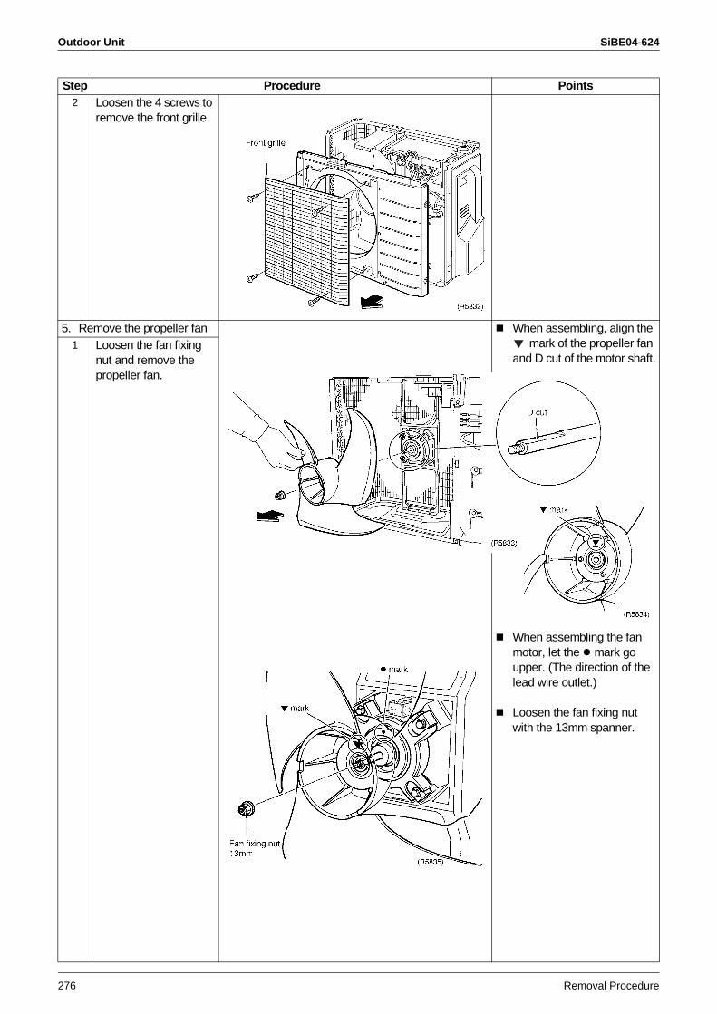
Outdoor Unit SiBE04-624
276 Removal Procedure
2 Loosen the 4 screws to remove the front grille.
5. Remove the propeller fan When assembling, align the mark of the propeller fan
and D cut of the motor shaft.1 Loosen the fan fixing
nut and remove the propeller fan.
When assembling the fan motor, let the mark go upper. (The direction of the lead wire outlet.)
Loosen the fan fixing nut with the 13mm spanner.
Step Procedure Points
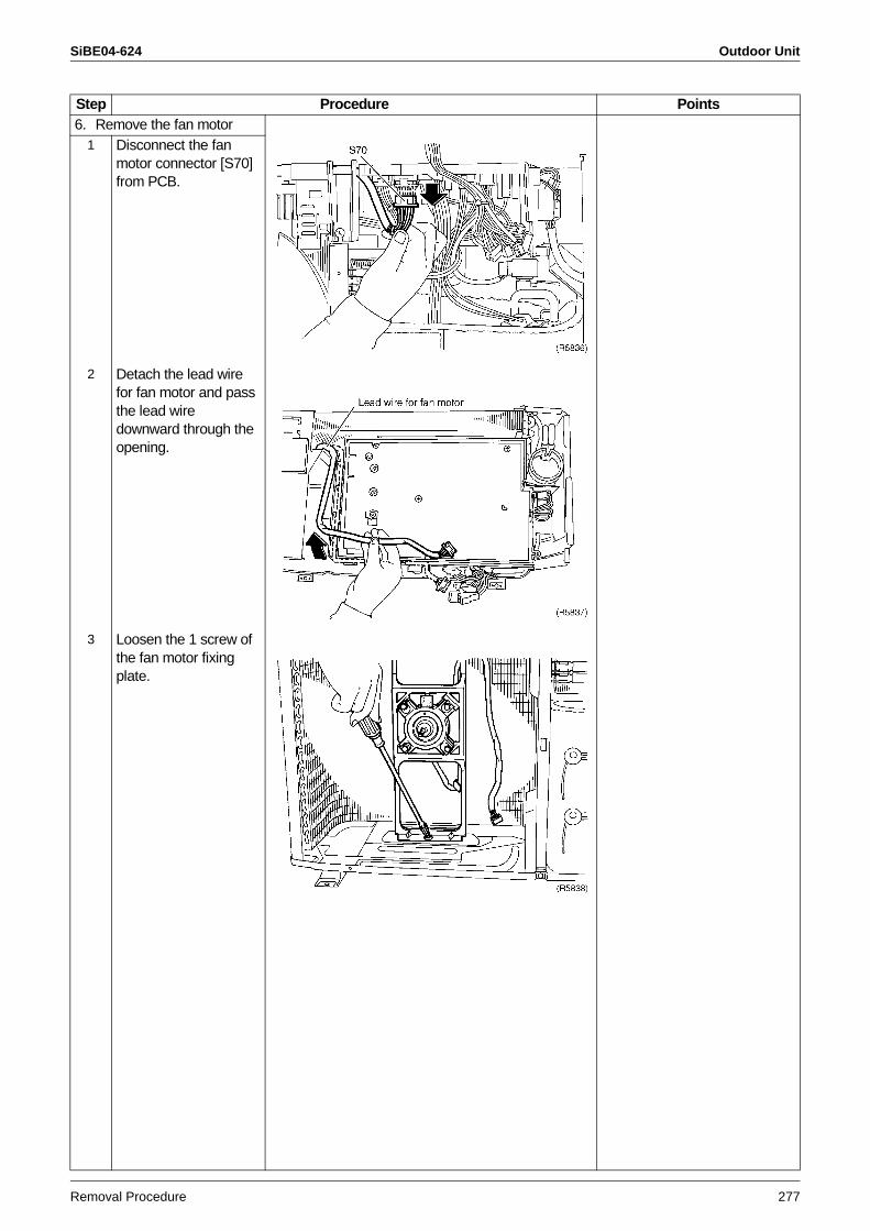
SiBE04-624 Outdoor Unit
Removal Procedure 277
6. Remove the fan motor1 Disconnect the fan
motor connector [S70] from PCB.
2 Detach the lead wire for fan motor and pass the lead wire downward through the opening.
3 Loosen the 1 screw of the fan motor fixing plate.
Step Procedure Points
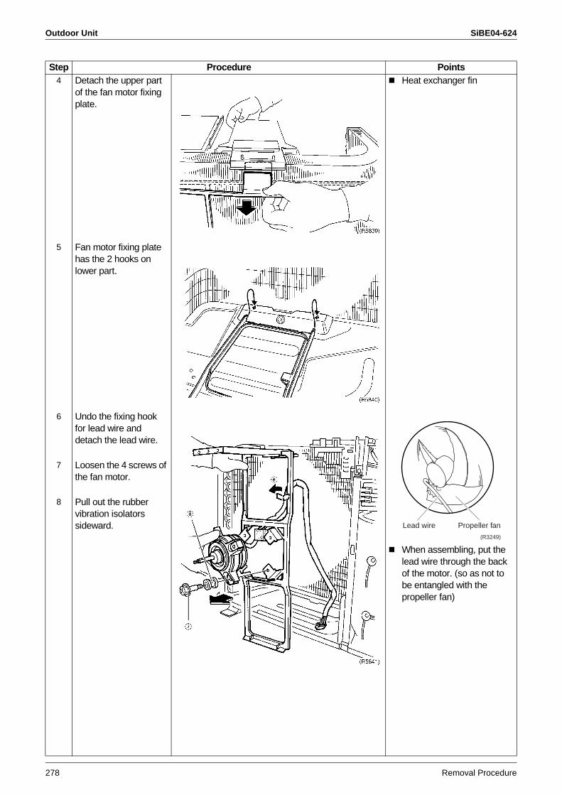
Outdoor Unit SiBE04-624
278 Removal Procedure
4 Detach the upper part of the fan motor fixing plate.
Heat exchanger fin
5 Fan motor fixing plate has the 2 hooks on lower part.
6 Undo the fixing hook for lead wire and detach the lead wire.
When assembling, put the lead wire through the back of the motor. (so as not to be entangled with the propeller fan)
7 Loosen the 4 screws of the fan motor.
8 Pull out the rubber vibration isolators sideward.
Step Procedure Points
(R3249)
Lead wire Propeller fan
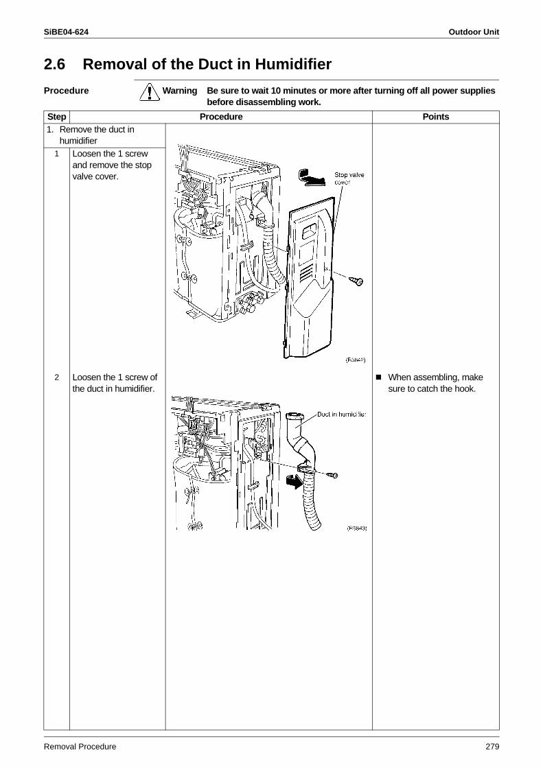
SiBE04-624 Outdoor Unit
Removal Procedure 279
2.6 Removal of the Duct in Humidifier
Procedure Warning Be sure to wait 10 minutes or more after turning off all power supplies before disassembling work.
Step Procedure Points1. Remove the duct in
humidifier1 Loosen the 1 screw
and remove the stop valve cover.
2 Loosen the 1 screw of the duct in humidifier.
When assembling, make sure to catch the hook.
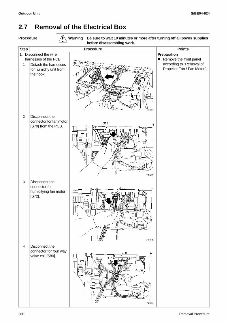
Outdoor Unit SiBE04-624
280 Removal Procedure
2.7 Removal of the Electrical Box
Procedure Warning Be sure to wait 10 minutes or more after turning off all power supplies before disassembling work.
Step Procedure Points1. Disconnect the wire
harnesses of the PCBPreparation
Remove the front panel according to "Removal of Propeller Fan / Fan Motor".
1 Detach the harnesses for humidify unit from the hook.
2 Disconnect the connector for fan motor [S70] from the PCB.
3 Disconnect the connector for humidifying fan motor [S72].
4 Disconnect the connector for four way valve coil [S80].
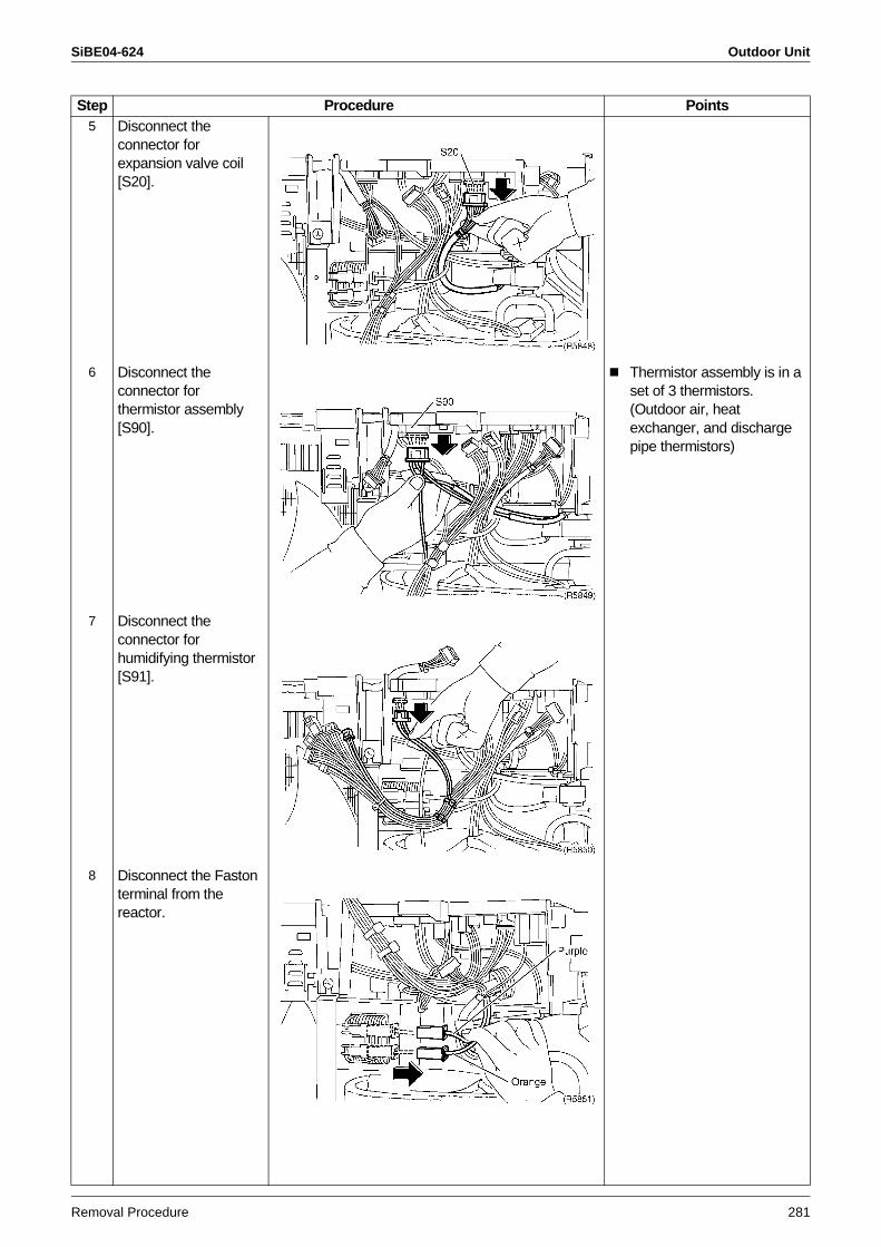
SiBE04-624 Outdoor Unit
Removal Procedure 281
5 Disconnect the connector for expansion valve coil [S20].
6 Disconnect the connector for thermistor assembly [S90].
Thermistor assembly is in a set of 3 thermistors. (Outdoor air, heat exchanger, and discharge pipe thermistors)
7 Disconnect the connector for humidifying thermistor [S91].
8 Disconnect the Faston terminal from the reactor.
Step Procedure Points
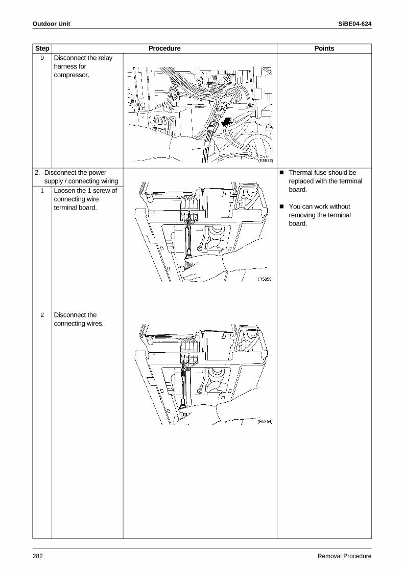
Outdoor Unit SiBE04-624
282 Removal Procedure
9 Disconnect the relay harness for compressor.
2. Disconnect the power supply / connecting wiring
Thermal fuse should be replaced with the terminal board.
You can work without removing the terminal board.
1 Loosen the 1 screw of connecting wire terminal board.
2 Disconnect the connecting wires.
Step Procedure Points
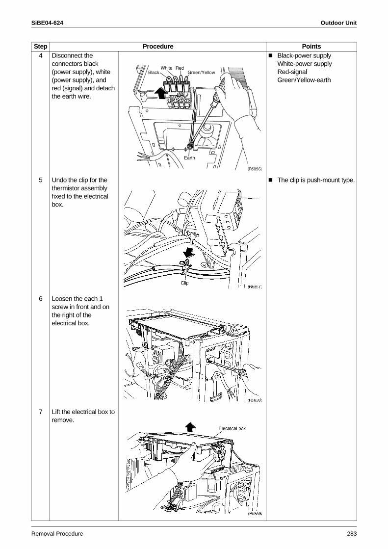
SiBE04-624 Outdoor Unit
Removal Procedure 283
4 Disconnect the connectors black (power supply), white (power supply), and red (signal) and detach the earth wire.
Black-power supplyWhite-power supplyRed-signalGreen/Yellow-earth
5 Undo the clip for the thermistor assembly fixed to the electrical box.
The clip is push-mount type.
6 Loosen the each 1 screw in front and on the right of the electrical box.
7 Lift the electrical box to remove.
Step Procedure Points
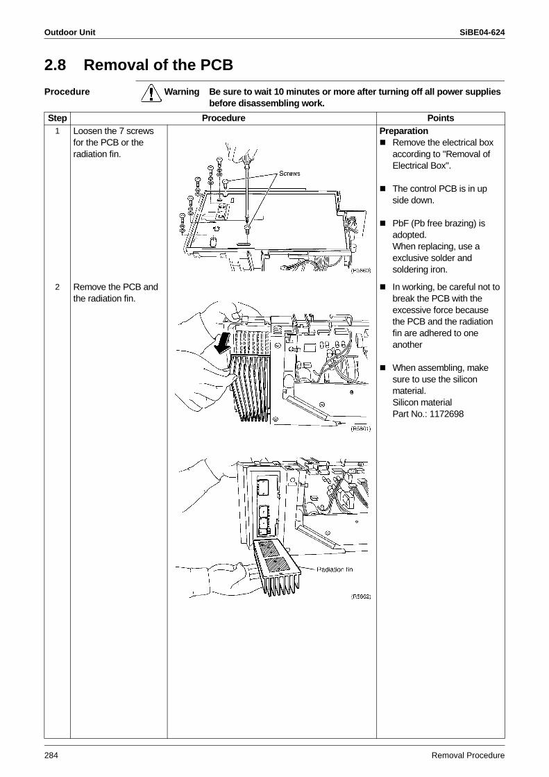
Outdoor Unit SiBE04-624
284 Removal Procedure
2.8 Removal of the PCB
Procedure Warning Be sure to wait 10 minutes or more after turning off all power supplies before disassembling work.
Step Procedure Points1 Loosen the 7 screws
for the PCB or the radiation fin.
PreparationRemove the electrical box according to "Removal of Electrical Box".
The control PCB is in up side down.
PbF (Pb free brazing) is adopted.When replacing, use a exclusive solder and soldering iron.
2 Remove the PCB and the radiation fin.
In working, be careful not to break the PCB with the excessive force because the PCB and the radiation fin are adhered to one another
When assembling, make sure to use the silicon material.Silicon materialPart No.: 1172698
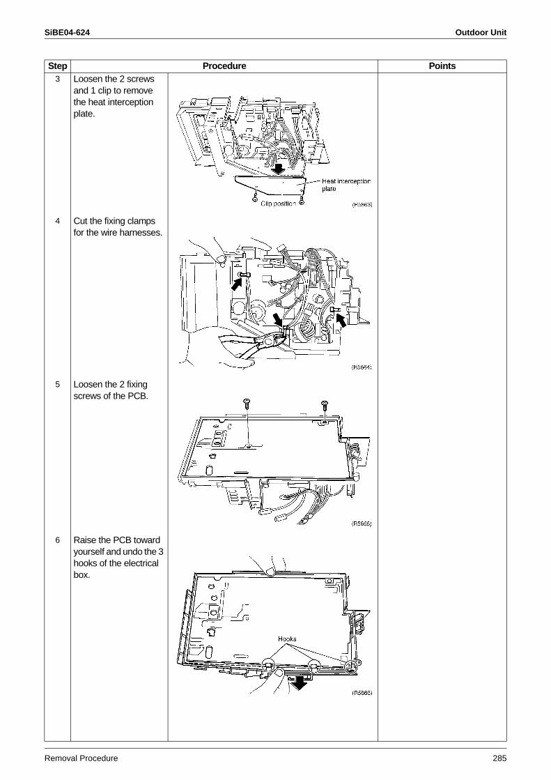
SiBE04-624 Outdoor Unit
Removal Procedure 285
3 Loosen the 2 screws and 1 clip to remove the heat interception plate.
4 Cut the fixing clamps for the wire harnesses.
5 Loosen the 2 fixing screws of the PCB.
6 Raise the PCB toward yourself and undo the 3 hooks of the electrical box.
Step Procedure Points
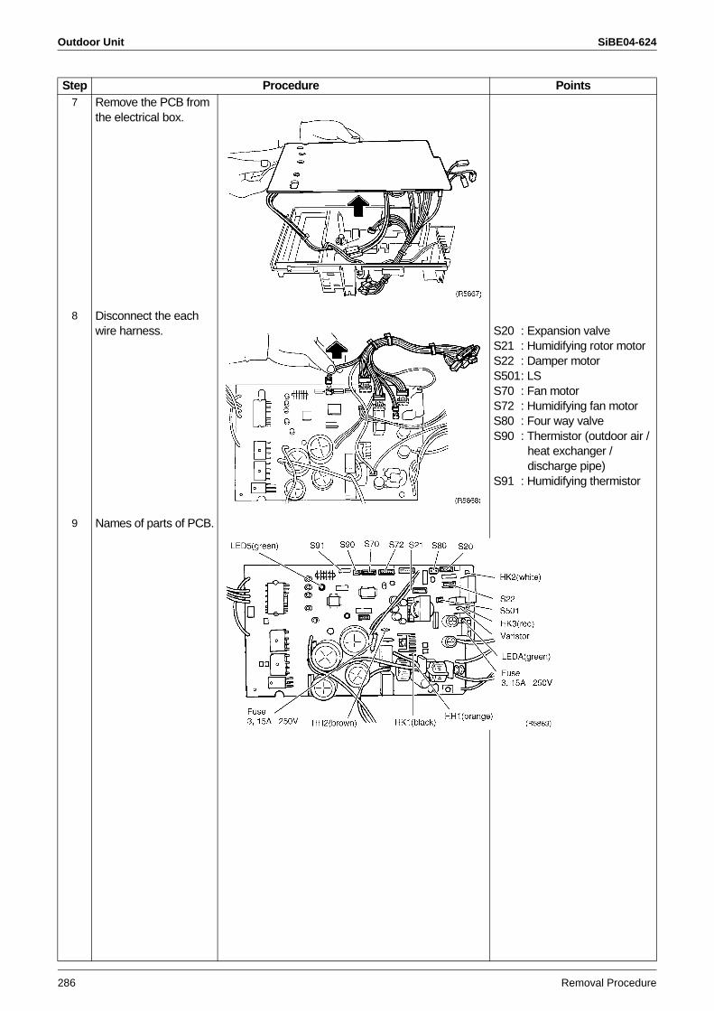
Outdoor Unit SiBE04-624
286 Removal Procedure
7 Remove the PCB from the electrical box.
8 Disconnect the each wire harness. S20 : Expansion valve
S21 : Humidifying rotor motorS22 : Damper motorS501: LSS70 : Fan motorS72 : Humidifying fan motorS80 : Four way valveS90 : Thermistor (outdoor air /
heat exchanger / discharge pipe)
S91 : Humidifying thermistor
9 Names of parts of PCB.
Step Procedure Points
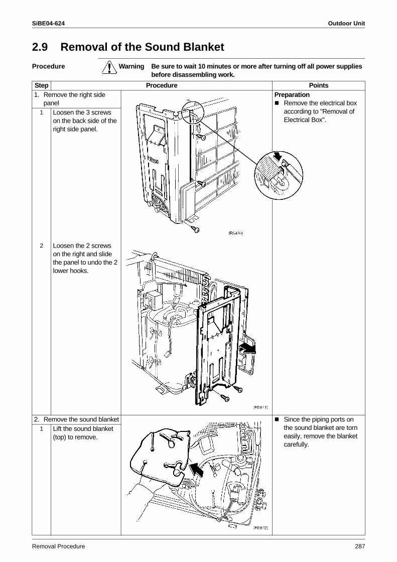
SiBE04-624 Outdoor Unit
Removal Procedure 287
2.9 Removal of the Sound Blanket
Procedure Warning Be sure to wait 10 minutes or more after turning off all power supplies before disassembling work.
Step Procedure Points1. Remove the right side
panelPreparation
Remove the electrical box according to "Removal of Electrical Box".
1 Loosen the 3 screws on the back side of the right side panel.
2 Loosen the 2 screws on the right and slide the panel to undo the 2 lower hooks.
2. Remove the sound blanket Since the piping ports on the sound blanket are torn easily, remove the blanket carefully.
1 Lift the sound blanket (top) to remove.
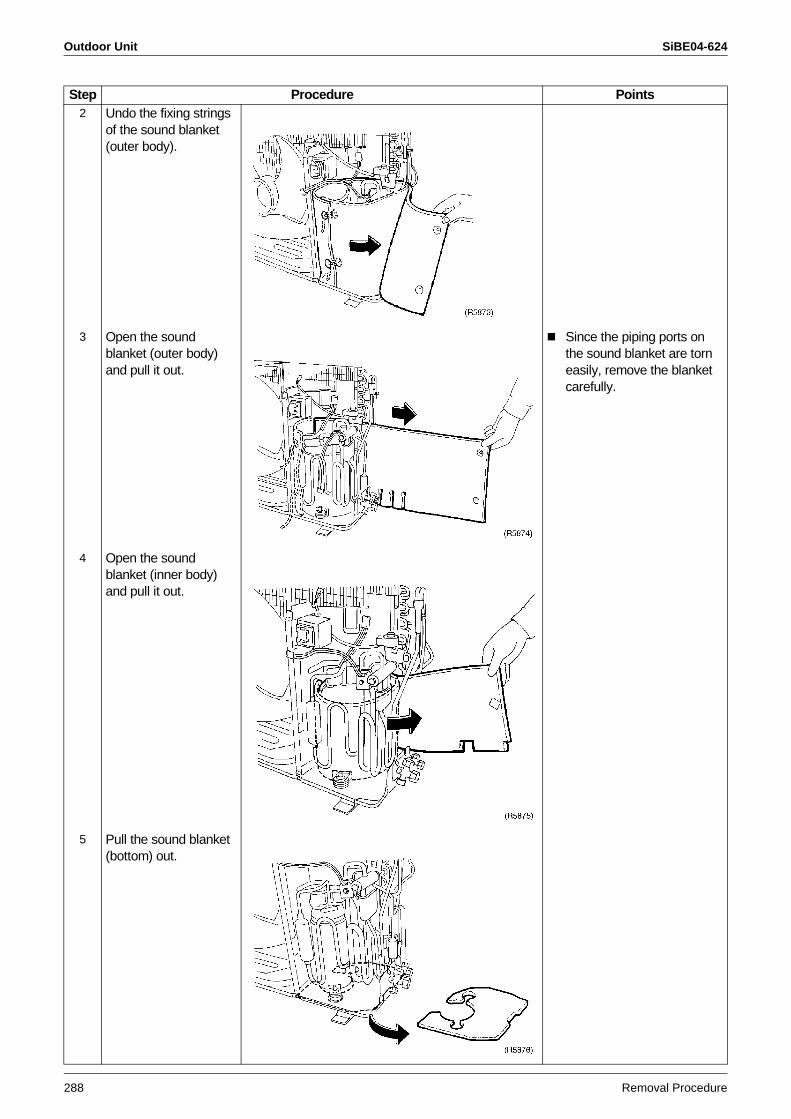
Outdoor Unit SiBE04-624
288 Removal Procedure
2 Undo the fixing strings of the sound blanket (outer body).
3 Open the sound blanket (outer body) and pull it out.
Since the piping ports on the sound blanket are torn easily, remove the blanket carefully.
4 Open the sound blanket (inner body) and pull it out.
5 Pull the sound blanket (bottom) out.
Step Procedure Points
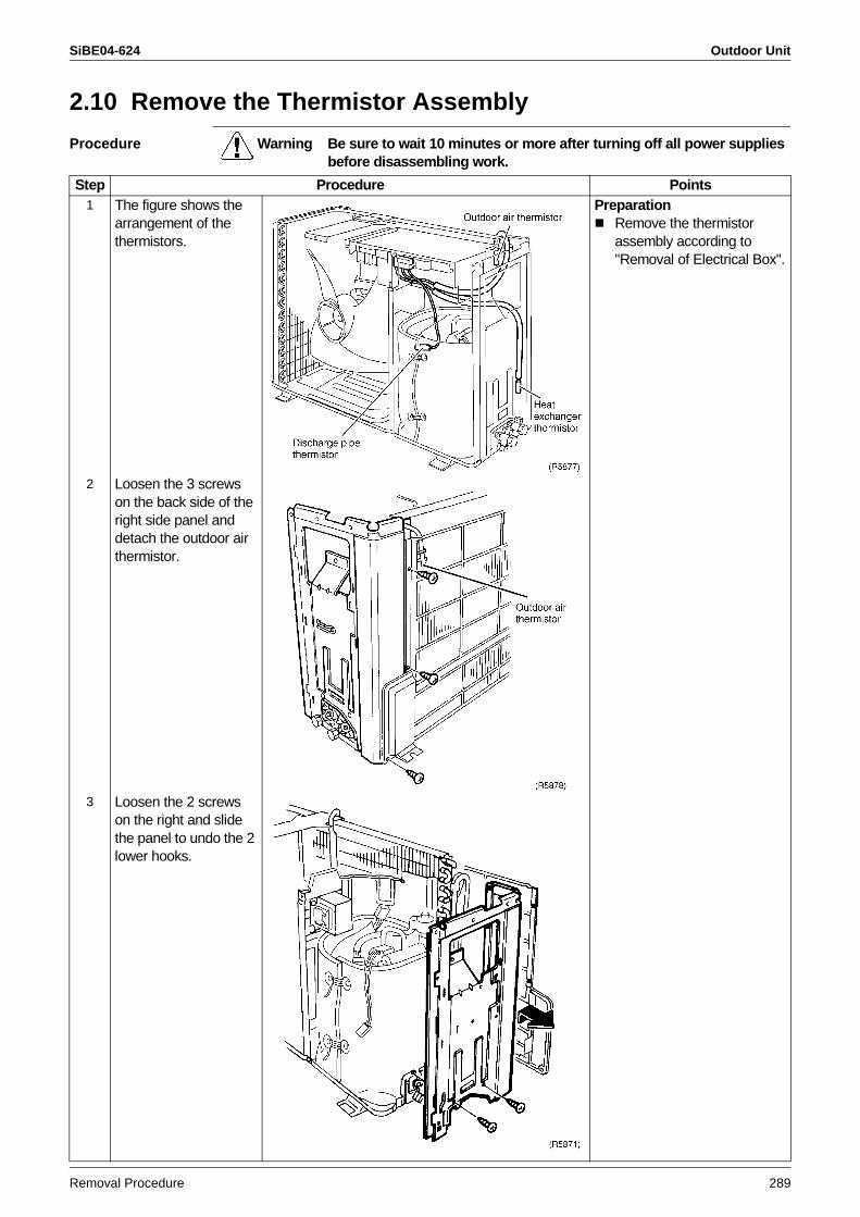
SiBE04-624 Outdoor Unit
Removal Procedure 289
2.10 Remove the Thermistor Assembly
Procedure Warning Be sure to wait 10 minutes or more after turning off all power supplies before disassembling work.
Step Procedure Points1 The figure shows the
arrangement of the thermistors.
PreparationRemove the thermistor assembly according to "Removal of Electrical Box".
2 Loosen the 3 screws on the back side of the right side panel and detach the outdoor air thermistor.
3 Loosen the 2 screws on the right and slide the panel to undo the 2 lower hooks.
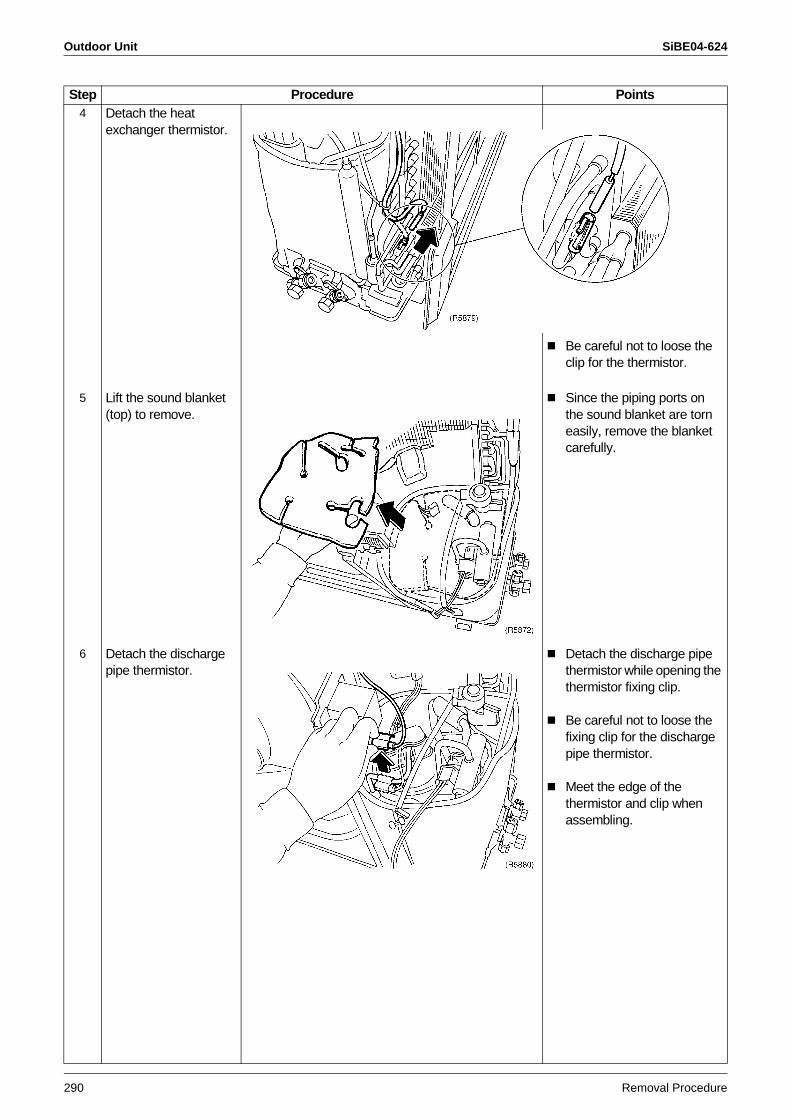
Outdoor Unit SiBE04-624
290 Removal Procedure
4 Detach the heat exchanger thermistor.
Be careful not to loose the clip for the thermistor.
5 Lift the sound blanket (top) to remove.
Since the piping ports on the sound blanket are torn easily, remove the blanket carefully.
6 Detach the discharge pipe thermistor.
Detach the discharge pipe thermistor while opening the thermistor fixing clip.
Be careful not to loose the fixing clip for the discharge pipe thermistor.
Meet the edge of the thermistor and clip when assembling.
Step Procedure Points
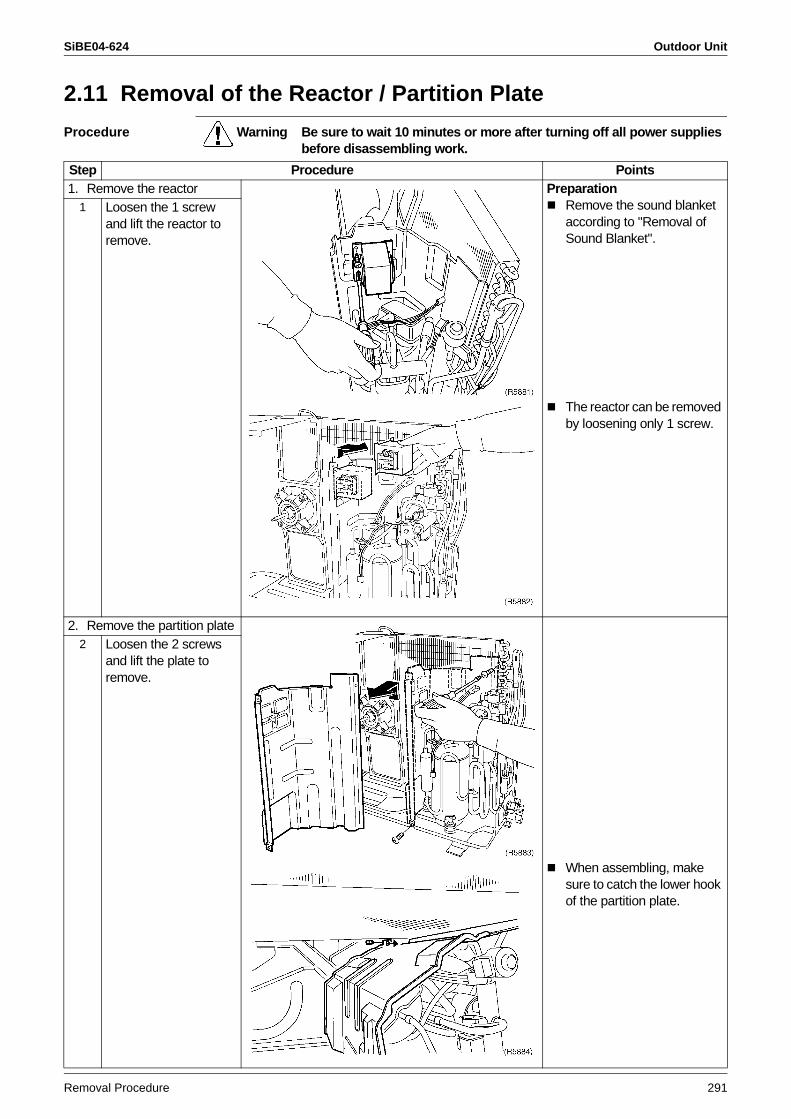
SiBE04-624 Outdoor Unit
Removal Procedure 291
2.11 Removal of the Reactor / Partition Plate
Procedure Warning Be sure to wait 10 minutes or more after turning off all power supplies before disassembling work.
Step Procedure Points1. Remove the reactor Preparation
Remove the sound blanket according to "Removal of Sound Blanket".
1 Loosen the 1 screw and lift the reactor to remove.
The reactor can be removed by loosening only 1 screw.
2. Remove the partition plate2 Loosen the 2 screws
and lift the plate to remove.
When assembling, make sure to catch the lower hook of the partition plate.
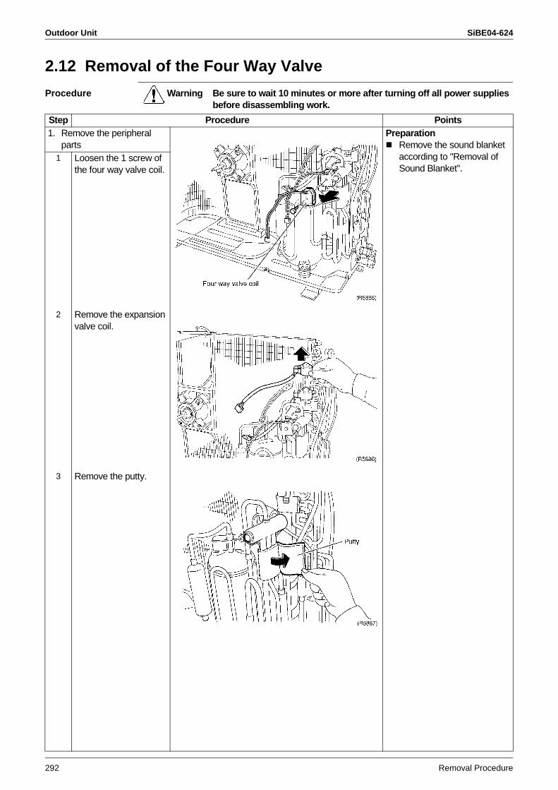
Outdoor Unit SiBE04-624
292 Removal Procedure
2.12 Removal of the Four Way Valve
Procedure Warning Be sure to wait 10 minutes or more after turning off all power supplies before disassembling work.
Step Procedure Points1. Remove the peripheral
partsPreparation
Remove the sound blanket according to "Removal of Sound Blanket".
1 Loosen the 1 screw of the four way valve coil.
2 Remove the expansion valve coil.
3 Remove the putty.
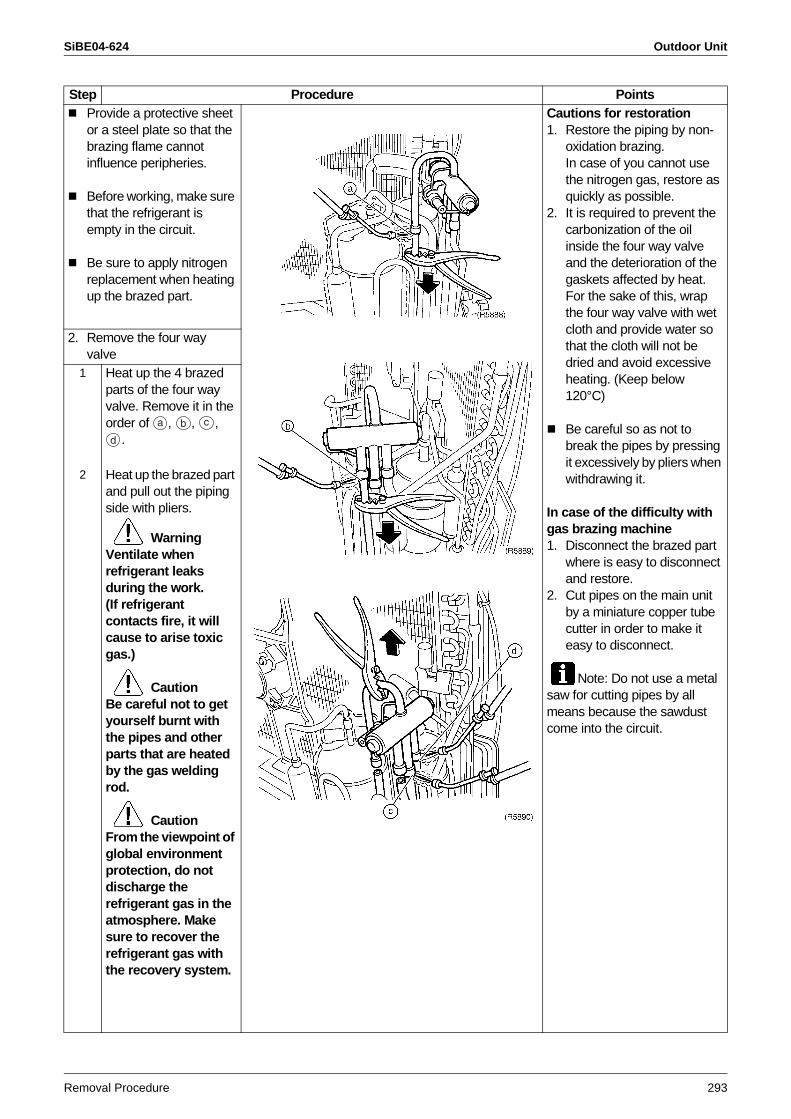
SiBE04-624 Outdoor Unit
Removal Procedure 293
Provide a protective sheet or a steel plate so that the brazing flame cannot influence peripheries.
Before working, make sure that the refrigerant is empty in the circuit.
Be sure to apply nitrogen replacement when heating up the brazed part.
Cautions for restoration1. Restore the piping by non-
oxidation brazing. In case of you cannot use the nitrogen gas, restore as quickly as possible.
2. It is required to prevent the carbonization of the oil inside the four way valve and the deterioration of the gaskets affected by heat. For the sake of this, wrap the four way valve with wet cloth and provide water so that the cloth will not be dried and avoid excessive heating. (Keep below 120°C)
Be careful so as not to break the pipes by pressing it excessively by pliers when withdrawing it.
In case of the difficulty with gas brazing machine 1. Disconnect the brazed part
where is easy to disconnect and restore.
2. Cut pipes on the main unit by a miniature copper tube cutter in order to make it easy to disconnect.
Note: Do not use a metal saw for cutting pipes by all means because the sawdust come into the circuit.
2. Remove the four way valve
1 Heat up the 4 brazed parts of the four way valve. Remove it in the order of , , ,
.
2 Heat up the brazed part and pull out the piping side with pliers.
WarningVentilate when refrigerant leaks during the work.(If refrigerant contacts fire, it will cause to arise toxic gas.)
CautionBe careful not to get yourself burnt with the pipes and other parts that are heated by the gas welding rod.
CautionFrom the viewpoint of global environment protection, do not discharge the refrigerant gas in the atmosphere. Make sure to recover the refrigerant gas with the recovery system.
Step Procedure Points
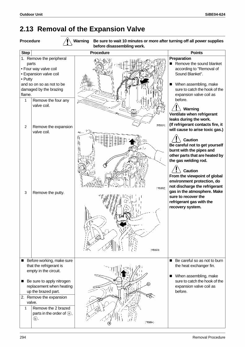
Outdoor Unit SiBE04-624
294 Removal Procedure
2.13 Removal of the Expansion Valve
Procedure Warning Be sure to wait 10 minutes or more after turning off all power supplies before disassembling work.
Step Procedure Points1. Remove the peripheral
parts• Four way valve coil• Expansion valve coil• Puttyand so on so as not to be damaged by the brazing flame.
PreparationRemove the sound blanket according to "Removal of Sound Blanket".
When assembling, make sure to catch the hook of the expansion valve coil as before.
WarningVentilate when refrigerant leaks during the work.(If refrigerant contacts fire, it will cause to arise toxic gas.)
CautionBe careful not to get yourself burnt with the pipes and other parts that are heated by the gas welding rod.
CautionFrom the viewpoint of global environment protection, do not discharge the refrigerant gas in the atmosphere. Make sure to recover the refrigerant gas with the recovery system.
1 Remove the four any valve coil.
2 Remove the expansion valve coil.
3 Remove the putty.
Before working, make sure that the refrigerant is empty in the circuit.
Be sure to apply nitrogen replacement when heating up the brazed part.
Be careful so as not to burn the heat exchanger fin.
When assembling, make sure to catch the hook of the expansion valve coil as before.
2. Remove the expansion valve.
1 Remove the 2 brazed parts in the order of ,
.
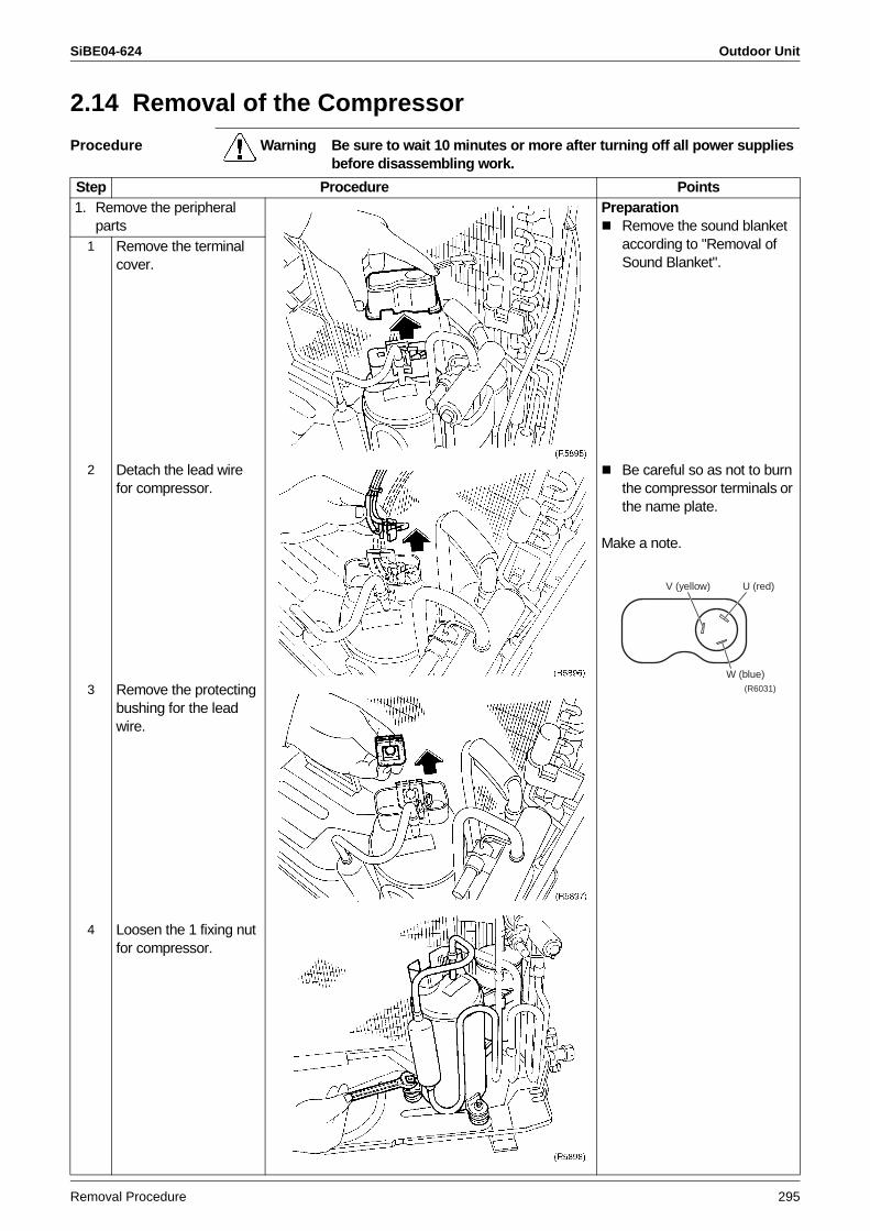
SiBE04-624 Outdoor Unit
Removal Procedure 295
2.14 Removal of the Compressor
Procedure Warning Be sure to wait 10 minutes or more after turning off all power supplies before disassembling work.
Step Procedure Points1. Remove the peripheral
partsPreparation
Remove the sound blanket according to "Removal of Sound Blanket".
1 Remove the terminal cover.
2 Detach the lead wire for compressor.
Be careful so as not to burn the compressor terminals or the name plate.
Make a note.
3 Remove the protecting bushing for the lead wire.
4 Loosen the 1 fixing nut for compressor.
V (yellow) U (red)
W (blue)(R6031)
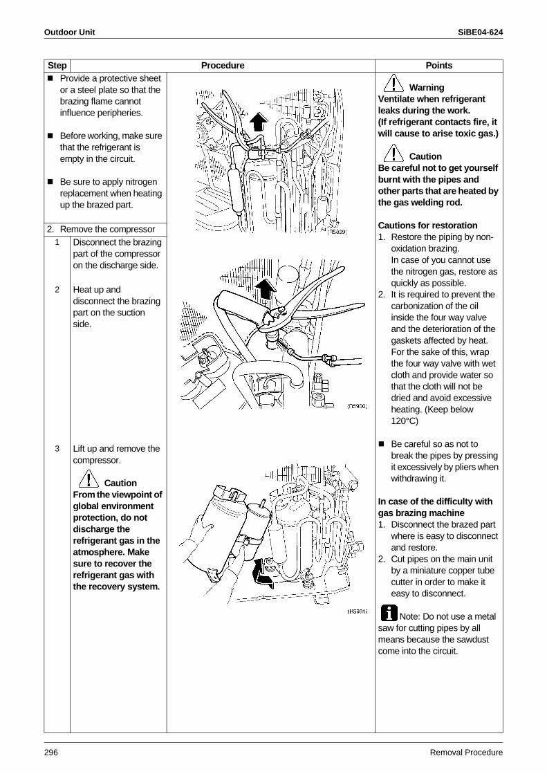
Outdoor Unit SiBE04-624
296 Removal Procedure
Provide a protective sheet or a steel plate so that the brazing flame cannot influence peripheries.
Before working, make sure that the refrigerant is empty in the circuit.
Be sure to apply nitrogen replacement when heating up the brazed part.
WarningVentilate when refrigerant leaks during the work.(If refrigerant contacts fire, it will cause to arise toxic gas.)
CautionBe careful not to get yourself burnt with the pipes and other parts that are heated by the gas welding rod.
Cautions for restoration1. Restore the piping by non-
oxidation brazing. In case of you cannot use the nitrogen gas, restore as quickly as possible.
2. It is required to prevent the carbonization of the oil inside the four way valve and the deterioration of the gaskets affected by heat. For the sake of this, wrap the four way valve with wet cloth and provide water so that the cloth will not be dried and avoid excessive heating. (Keep below 120°C)
Be careful so as not to break the pipes by pressing it excessively by pliers when withdrawing it.
In case of the difficulty with gas brazing machine 1. Disconnect the brazed part
where is easy to disconnect and restore.
2. Cut pipes on the main unit by a miniature copper tube cutter in order to make it easy to disconnect.
Note: Do not use a metal saw for cutting pipes by all means because the sawdust come into the circuit.
2. Remove the compressor1 Disconnect the brazing
part of the compressor on the discharge side.
2 Heat up and disconnect the brazing part on the suction side.
3 Lift up and remove the compressor.
CautionFrom the viewpoint of global environment protection, do not discharge the refrigerant gas in the atmosphere. Make sure to recover the refrigerant gas with the recovery system.
Step Procedure Points
SiBE04-624
Others 297
Part 8Others
1. Others .................................................................................................2981.1 Test Run from the Remote Controller ..................................................2981.2 Field Setting .........................................................................................299
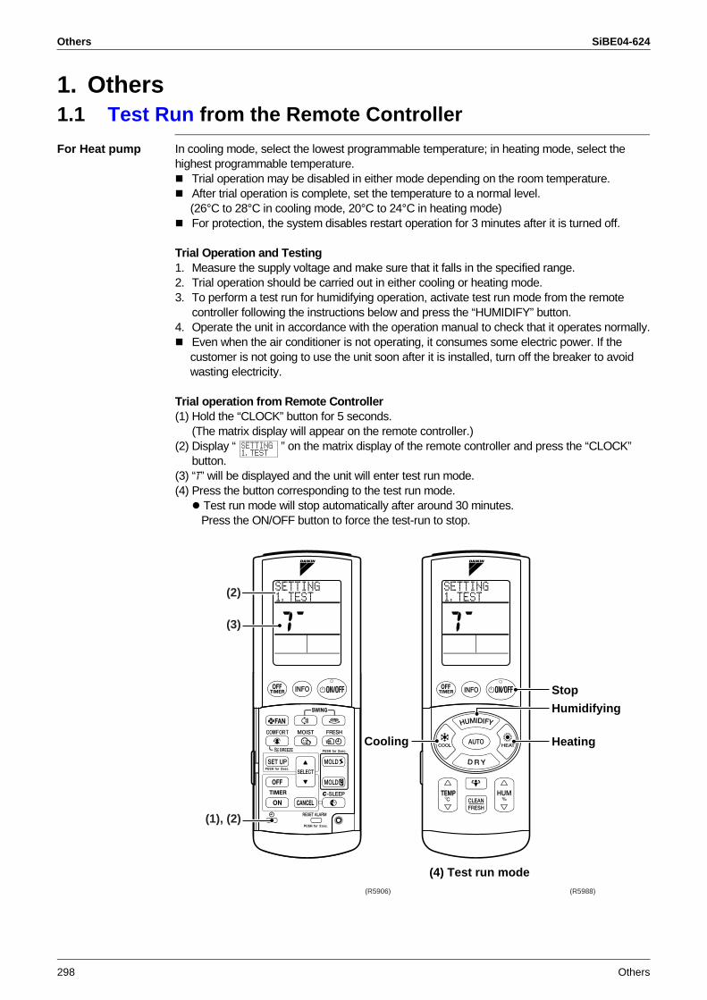
Others SiBE04-624
298 Others
1. Others1.1 Test Run from the Remote Controller
For Heat pump In cooling mode, select the lowest programmable temperature; in heating mode, select the highest programmable temperature.
Trial operation may be disabled in either mode depending on the room temperature.After trial operation is complete, set the temperature to a normal level.(26°C to 28°C in cooling mode, 20°C to 24°C in heating mode)For protection, the system disables restart operation for 3 minutes after it is turned off.
Trial Operation and Testing1. Measure the supply voltage and make sure that it falls in the specified range.2. Trial operation should be carried out in either cooling or heating mode.3. To perform a test run for humidifying operation, activate test run mode from the remote
controller following the instructions below and press the “HUMIDIFY” button.4. Operate the unit in accordance with the operation manual to check that it operates normally.
Even when the air conditioner is not operating, it consumes some electric power. If the customer is not going to use the unit soon after it is installed, turn off the breaker to avoid wasting electricity.
Trial operation from Remote Controller(1) Hold the “CLOCK” button for 5 seconds.
(The matrix display will appear on the remote controller.)(2) Display “ ” on the matrix display of the remote controller and press the “CLOCK”
button.(3) “T” will be displayed and the unit will enter test run mode.(4) Press the button corresponding to the test run mode.
Test run mode will stop automatically after around 30 minutes. Press the ON/OFF button to force the test-run to stop.
(R5906) (R5988)
(2)
(3)
(1), (2)
Cooling
Humidifying
Heating
(4) Test run mode
Stop
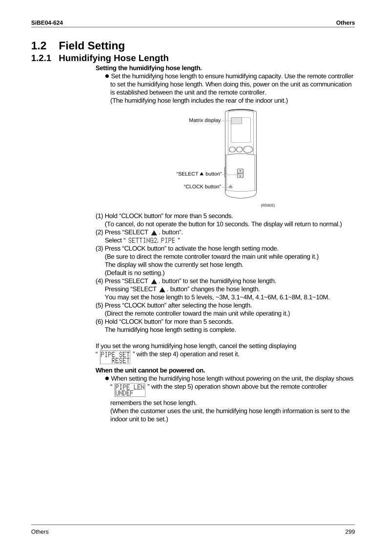
SiBE04-624 Others
Others 299
1.2 Field Setting1.2.1 Humidifying Hose Length
Setting the humidifying hose length. Set the humidifying hose length to ensure humidifying capacity. Use the remote controller to set the humidifying hose length. When doing this, power on the unit as communication is established between the unit and the remote controller. (The humidifying hose length includes the rear of the indoor unit.)
(1) Hold “CLOCK button” for more than 5 seconds.(To cancel, do not operate the button for 10 seconds. The display will return to normal.)
(2) Press “SELECT . button”.Select “ ”
(3) Press “CLOCK button” to activate the hose length setting mode. (Be sure to direct the remote controller toward the main unit while operating it.)The display will show the currently set hose length. (Default is no setting.)
(4) Press “SELECT . button” to set the humidifying hose length.Pressing “SELECT . button” changes the hose length.You may set the hose length to 5 levels, ~3M, 3.1~4M, 4.1~6M, 6.1~8M, 8.1~10M.
(5) Press “CLOCK button” after selecting the hose length. (Direct the remote controller toward the main unit while operating it.)
(6) Hold “CLOCK button” for more than 5 seconds.The humidifying hose length setting is complete.
If you set the wrong humidifying hose length, cancel the setting displaying “ ” with the step 4) operation and reset it.
When the unit cannot be powered on. When setting the humidifying hose length without powering on the unit, the display shows “ ” with the step 5) operation shown above but the remote controller
remembers the set hose length.(When the customer uses the unit, the humidifying hose length information is sent to the indoor unit to be set.)
(R5905)
“CLOCK button”
Matrix display
“SELECT button”
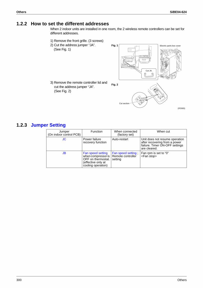
Others SiBE04-624
300 Others
1.2.2 How to set the different addressesWhen 2 indoor units are installed in one room, the 2 wireless remote controllers can be set for different addresses.
1.2.3 Jumper Setting
1) Remove the front grille. (3 screws)2) Cut the address jumper “JA”. (See Fig. 1)
3) Remove the remote controller lid and cut the address jumper “J4”. (See Fig. 2)
Electric parts box cover
Cut JA.
Fig. 1
J4
Fig. 2
Cut section
(R5989)
Jumper (On indoor control PCB)
Function When connected (factory set)
When cut
JC Power failure recovery function
Auto-restart Unit does not resume operation after recovering from a power failure. Timer ON-OFF settings are cleared.
JB Fan speed setting when compressor is OFF on thermostat.(effective only at cooling operation)
Fan speed setting ; Remote controller setting
Fan rpm is set to “0” <Fan stop>
SiBE04-624
Appendix 301
Part 9Appendix
1. Piping Diagrams..................................................................................3021.1 Indoor Units ..........................................................................................3021.2 Outdoor Units .......................................................................................302
2. Wiring Diagrams..................................................................................3032.1 Indoor Units ..........................................................................................3032.2 Outdoor Units .......................................................................................303
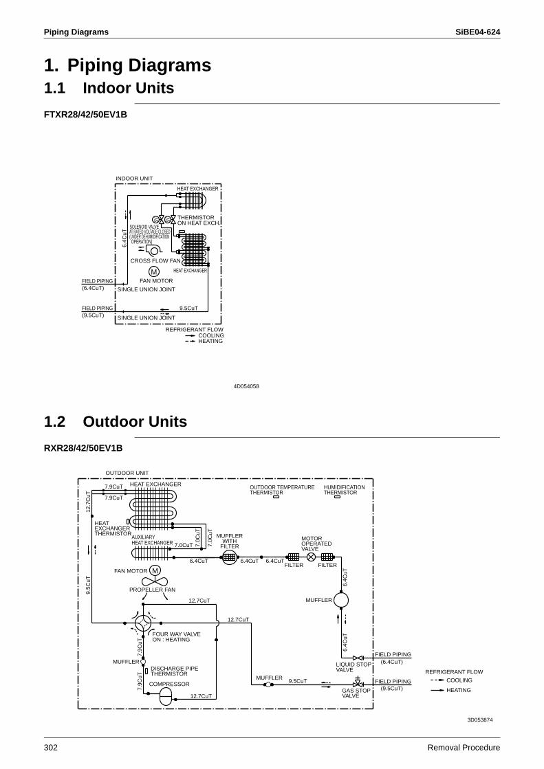
Piping Diagrams SiBE04-624
302 Removal Procedure
1. Piping Diagrams1.1 Indoor Units
FTXR28/42/50EV1B
1.2 Outdoor Units
RXR28/42/50EV1B
M
THERMISTORON HEAT EXCH.
FIELD PIPING
HEAT EXCHANGER
HEAT EXCHANGER
SINGLE UNION JOINT
REFRIGERANT FLOW
(6.4CuT)
(UNDER DEHUMIDIFICATIONOPERATION)
HEATINGCOOLING
(9.5CuT)
INDOOR UNIT
9.5CuT
CROSS FLOW FAN
AT RATED VOLTAGE:CLOSED
SINGLE UNION JOINTFAN MOTORFIELD PIPING
SOLENOID VALVE
6.4C
uT
SV SV
4D054058
6.4C
uT
DISCHARGE PIPETHERMISTOR
12.7
CuT
6.4CuT
9.5CuT
HEAT EXCHANGER
FILTER
FOUR WAY VALVEON : HEATING
LIQUID STOPVALVE
FIELD PIPING
12.7CuT
7.9C
uT
FAN MOTOR
6.4CuT
HEATEXCHANGERTHERMISTOR
FILTER
COOLINGREFRIGERANT FLOW
12.7CuT
OUTDOOR TEMPERATURETHERMISTOR
6.4CuT
(9.5CuT)
MUFFLERWITH
FILTER
HEATING
PROPELLER FAN9.5C
uT
7.9CuT
MUFFLER
7.0C
uT
MUFFLER
12.7CuT
7.0CuT
HUMIDIFICATIONTHERMISTOR
OUTDOOR UNIT
GAS STOPVALVE
AUXILIARYHEAT EXCHANGER
7.9CuT
7.0C
uT
FIELD PIPINGCOMPRESSOR
MOTOROPERATEDVALVE
M
6.4C
uT
(6.4CuT)
7.9C
uT
MUFFLER
3D053874
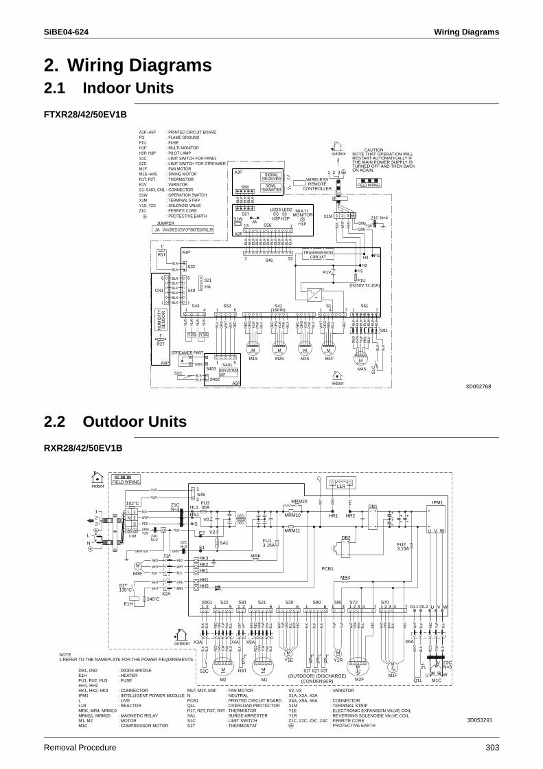
SiBE04-624 Wiring Diagrams
Removal Procedure 303
2. Wiring Diagrams2.1 Indoor Units
FTXR28/42/50EV1B
2.2 Outdoor Units
RXR28/42/50EV1B
FIELD WIRING.
outdoor
R1T
t°
LED2
H2P
M
Y2S
indoor
TURNED OFF AND THEN BACK
RESTART AUTOMATICALLY IFNOTE THAT OPERATION WILL
THE MAIN POWER SUPPLY IS
ON AGAIN.
CAUTION
SIGNALRECEIVER
MM
t°
R2T
Y1S
MULTIMONITOR
H1P
SIGNALTRANSMITTER
LED3
H3P
M
6
RED
S515
+
1
BLK
S402
5
4S1
7
M3S
BLK
JAZ1C N=4
M2S
GRN
1
1
13
A5P
RED
BLK
S2C
BLK
BLK
RED BL
K
S216
S401
H2
HU
MID
ITY
SEN
SOR
BLK
1
GRN
S1C
S32
7
BLK
S91
BLK
HIGH VOLTAGEUNIT
M1F
BLK
1
(16PIN)
ORG
M
JA
A4P
2
YLW
3
BLK
JUMPER
BLK
BLK
ORG
FG
/
BLK
BLK
TRANSMISSIONCIRCUIT
BLK
ORG
A3P
4
BLK
BLU
BLK
R1V
1
CN1
S41
1
-
H1
BLK
PNK
A1PPN
K
BLK
YLW
H3
S43
BLK
BLK
BLU
A2P
ORG
S57
BLK
2
1
BLK
BLK
1PN
KS52
S1WYLW
YLW
BLK
BLK
RED
BLK
YLW
REDYLW
M1S
BLK
AN ADDRESS SETUP OF REMOTECONTROLLER
WHT
BLK
X1M
(H250V,T3.15A)
S403
BLU BL
K
S48
ORG
YLW
13
RED
BLK
STREAMER PART
-
PNK
WHT
BLK HA
S56 WHT
RED
BLK
1
S46
BLK
M4S
WIRELESSREMOTE
CONTROLLER
BLK
S58
1
BLU
YLW
ORG
BLU
YLW BL
K
BLU
BRN
BLK
BLK
GRN
: PROTECTIVE EARTH 3
F1U
: FLAME GROUND: FUSE
: PILOT LAMP
: FAN MOTOR
: PRINTED CIRCUIT BOARD
R1T, R2T
: CONNECTOR: OPERATION SWITCH: TERMINAL STRIP
: SWING MOTORM1S~M4S
F1U
M1F
H2P, H3P
S1~S403, CN1
FG
X1MS1W
: THERMISTOR
A1P~A5P
: MULTI MONITORH1P
: LIMIT SWITCH FOR PANELS1C: LIMIT SWITCH FOR STREAMERS2C
: VARISTORR1V
: SOLENOID VALVEY1S, Y2S: FERRITE COREZ1C
3D052768
LN
1
32 -
+-+
: PROTECTIVE EARTH
IPM1
+
WVU-
M
M1~M
NOTE1.REFER TO THE NAMEPLATE FOR THE POWER REQUIREMENTS.
L1R
1~M
-
~ +
~
FIELD WIRING.
M
indoor
~
+DB1
-
~
outdoor
HK1
S21
M
X4A
E1H : HEATERR1T
BLK
-MRM10
RED
IPM1 : INTELLIGENT POWER MODULE
6
BRN
1
MR4
Z1CN=3
M2F
X1A, X2A, X3AX4A, X5A, X6A : CONNECTOR
S
WHT
Y1R
L : LIVE
WHT
DB2
6 7
S45
E1
-
X3A
S1T135°C
HR1
BLK
S91 S80
PNK
MRM11
MRK
Q1L
X1M : TERMINAL STRIP
Z4CN=2
YLW
HN1
X6A
YLW
ORG
R4T
t°
BLK
BLK
BLU
M3F
GRN/YLW
(CONDENSER)
SA1 : SURGE ARRESTER
BLU
PNK
ORG
S203
M1F, M2F, M3F : FAN MOTOR
1
1
3.15A
N
X1A
RED
t°
YLW
2 V W
3
M1, M2 : MOTOR
(OUTDOOR) (DISCHARGE)
BLU
FU2
BRN
OL13
HL1
ORG
RED
Z2CN=3
W
2
BLK
1
BLU
WHT
Y1R : REVERSING SOLENOIDE VALVE COIL
WHT
U1
2
R3T
V3
HH1, HH2HK1, HK2, HK3 : CONNECTOR
1
FU1, FU2, FU3 : FUSE
V2
BLK
YLW
RED
Y1E : ELECTRONIC EXPANSION VALVE COIL
M
S1C
102°C
L
BLU
N : NEUTRAL
L1R : REACTOR
GRN
BRN
X2A
FU1
S22
BLK
PNK
BLK
ORG
S90
BLK
WHT
X1M
YLW
PPL
RED
1
M1C
GRY
RED
t°
PCB1
WHT
ORG
S1T : THERMOSTAT
OL2
GRN/YLW
HH1
MRK, MR4, MRM10MRM11, MRM20 : MAGNETIC RELAY
YLW
RED
S1C : LIMIT SWITCH
3S70
3.15A
YLW
SA1
BLU
ORG
YLW
BLU
RED
ORG
BLU
PCB1 : PRINTED CIRCUIT BOARD
1
HK3
PNK
ORG
Y1E
HK2
3
R1T, R2T, R3T, R4T : THERMISTOR
V
X5A
HH2
S5014
+
Z1C, Z2C, Z3C, Z4C : FERRITE CORE
E2
+
RED
30A
HR2
R2T
E1H
M1C : COMPRESSOR MOTOR
BLK
YLW
BLK
S72
WHT
4
BLU
BLK
M2
1
RED
2 6
RED
YLW
RED
ORG
M1
FU3
BLK
BRN
1
GRY
WHT
BRN
Q1L : OVERLOAD PROTECTOR
DB1, DB2 : DIODE BRIDGE
5
YLW
M1F
YLW
Z3CN=3
7
U
1
MRM20
V2, V3 : VARISTOR
240°C2
WHT
WHT
GRY
~
t°
3D053291
Wiring Diagrams SiBE04-624
304 Removal Procedure
Specifications, designs and other content appearing in this brochure are current as of August 2006 but subject to change without notice.SiBE 04-624Printed in Japan 08/2006 B AK