Embed Size (px)
Citation preview

Air Circuit Breakers

Larsen & Toubro is a technology-driven
company that infuses engineering with
imagination. The Company offers a wide
range of advanced solutions in the field of
Engineering, Construction, Electrical &
Automation, Machinery and Information
Technology.
L&T Switchgear, a part of the Electrical &
Automation business, is India's largest
manufacturer of low voltage switchgear,
with the scale, sophistication and range to
meet global benchmarks. With over seven
decades of experience in this field, the
Company today enjoys a leadership
position in the Indian market with a growing
international presence.
It offers a complete range of products
including powergear, controlgear, industrial
automation, building electricals &
automation, reactive power management,
energy meters, and protective relays.
These products conform to Indian and
International Standards.
Switchgear Factory, Ahmednagar
Switchgear Factory, Navi Mumbai
Switchgear Factory, Vadodara
ABOUT US
1

L&T’s Air Circuit Breakers (ACBs) are specially designed for extreme tropical conditions and have a proven
track record of more than 45 years. Presently more than 5,00,000 Air Circuit Breakers supplied by L&T are
being used for diverse applications. The Air Circuit Breakers provide technologically driven
solutions to meet customer needs.
Unique feature of lcu=lcs=lcw for 1 second across the entire range. This ensures complete selectivity for
system with time based discrimination.
Inherent design to perform in extreme tropical conditions. Typical site conditions like high ambient
temperature, humidity and dusty environment are best handled by ACBs without compromising
on performance and safety.
Complete selectivity
Perfect for indian conditions
Optimal compactness
Widest choice of over current protection releases
Elegant design & rugged construction
Range to meet every customer’s need
Designed to ensure
�Low inherent temperature rise
�Adequate interface clearances
�Advance micro-controller based with option of communication & metering-SR71
�Micro processor based releases-
�Thermo-magnetic release-DN1
�Common door cutout for entire range
�Left aligned cutout for all ratings
Various options to choose from
�Breaking capacity from 50kA to 100kA
�3 Pole or 4 Pole configuration
�Fixed or Drawout version
�Auto reset mechanism
�Independent manual or stored energy type, manual or electrically operated mechanism
�Different terminal orientations : Flat, Horizontal and Vertical
SR18/SR18G/SR21i/SR18G & with current meteringSR18Gi
AIR CIRCUIT BREAKERS
2

New User Friendly Feature
User Friendly Features
Safety
Conformance to Standards
�Operational
�
�Superior quality engineering grade plastics used for insulation purpose; conforms to Glow wire test
(Ref: IEC 60695-2-1)
�In-built mechanical anti-pumping
�In-built rating error preventor in drawout ACBs ensure correct rating of drawout portion in corresponding
cradle
�Safety shutters prevent accidental contact with live cradle terminals
�Variety of Safety Interlocks
�Easily removable arc chutes without use of any tool
�Operating voltage ranges from 10% Un to 110% Un for shunt release ensures intentional tripping even at
high voltage drops during short-circuit
�
�IEC - 60947 (Part 1 & 2)
�IS/IEC - 60947 (Part 1 & 2)
�IEC 60695 - 2 - 1
�BS EN 60947 - 2
Counter will be standard offering from rating 4000A and above
in DN1 release
Jaws on breaker facilitate ease of maintenance & replacement of contact jaws
to prevent auto-reclosing of ACB on persisting faults
Transparent safety shutter offers easy inspection of cradle contacts & reduces the maintenance time
690V Application for C-Power ACB
Solution for 690V application available in C-Power Family. For further details please consult our nearest
branch office.
Breakers for Corrosive Environment
Solution for harsh/corrosive environment available in C-Power Family. For further details please consult our
nearest branch office.
�Front accessible over current release settings, telescopic racking handle and various racking interlocks;
no need to open the panel door
�Unique ‘Maintenance position’ in drawout type ACBs to facilitate maintenance & inspection without
removing ACB from the panel
�Multitap CTs for enhancing protection range
�Wide variety of Amperemetric and Voltmetric releases
�Fully rated neutral pole for the entire range
�Lockable sliding shutters to prevent unauthorized access to “TRIP” and “CLOSE” push buttons
�Can be used as an ON / OFF Load Isolator
�Extendable Electrical Life:
- By replacing the arcing contacts at site, for all ratings
- Without changing pole assembly
�Programmable SICs: Auxiliary contacts in drawout ACBs are programmable for only Service, Only Test,
Test and Service, and All Positions
�Protection releases are easily interchangeable at site
�Facility for site conversion of manually operated ACBs to electrically operated ACBs
Special Applications
3

CN-CS : S1
CN-CS : E
50kA50kA 50kA 50kA
50kA 50kA
50kA 50kA
630A400A
CN-CS : C
CN-CS : H
CN-CS : H2
CN-CS : H1/H
Frame-1
50kA 50kA 50kA 50kA
65kA 65kA 65kA 65kA
800A 1000A 1250A 1600A
Icu = Ics = Icw for 1 sec
Frame-1 Frame-2
50kA
50kA 50kA 50kA 50kA
60kA 60kA
Frame-3Frame-2
55kA 60kA
75kA 75kA
75kA
100kA
2000A 2500A 3200A
75kA
100kA
95kA 95kA
4000A 5000A 6300A
Frame-4
Rated Current
50kA
Frame-1
RANGE
4
NEW
Note : 3200A H2 / 4000A H2 will replace 3200A H0 / 4000A H0. Spares for 3200 / 4000 A H0 will be available.
Breaking Capacities:

‡ Electrical life = Mechanical life. However, arcing contacts need to be replaced depending upon wear & tear.
��Please consult us.
* Please consult us for application at dc voltages & higher operational voltage upto 690V AC.
5 Available in Control Box version#
TECHNICAL DATA SHEET
E
3
50
-
50
-
50
50
-
105
-
#S1
50
-
50
-
50
50
25
105
-
C
3/4
50
35
50
35
50
50
35
105
73.5
H
65
50
65
50
65
65
50
143
105
E
3
50
-
50
-
50
50
-
105
-
#
1000
1000
415
1000
394
326
414
Rating (A)
Type Designation
Rated current (A) at 50°C
Rated operational voltage (V), 50/60Hz
Rated insulation voltage (V), 50/60Hz
No. of poles
380/415/500V
690V
380/415/500V
690V
0.5 sec
1 sec
3 sec
380/415/500V
690V
Fixed
Draw out
In
*Ue
Ui
Icu
Ics
Icw
Icm
630
415
1000
800
800
415
1000
C
3/4
50
35
50
35
50
50
35
105
73.5
H
65
50
65
50
65
65
50
143
105
394
326
414
3 Pole
4 Pole
3 Pole
4 Pole
H
W
D
H
W
D
44 4
40
60
B
�
40
60
B
�
40
60
B
�
Rated impulse withstand voltage
of main circuit (kV)
Rated making capacity
50/60Hz (kA peak)
S1
50
-
50
-
50
50
25
105
-
�
�
�
�
8000
443
�
�
�
�
20000
8000
468
399
487
587
Rated impulse withstand voltage
of aux. circuit (kV)Uimp
�
�
�
�
8000
�
x
�
x
15000
6000
385
316
-
449
-
-
-
-
�
�
�
�
8000
443
�
�
�
�
20000
8000
468
399
487
587
Uimp
�
�
�
�
8000
�
x
�
x
6000
385
316
-
449
-
-
-
-
Typical opening time (ms)
Typical closing time (ms)
Utilization category
Suitability for isolation
Fixed
Draw out
Manual
Electrical
‡Electrical & Mechanical life (operating cycles)
Electrical life without maintenance
Dimensions (in mm)
400
#E
400
415
1000
3
50
-
50
-
50
50
-
105
-
40
60
B
x
x
15000
6000
385
316
-
449
-
-
-
-
�
�
�
4
8
E
3
50
-
50
-
50
50
-
105
-
#
�
�
x
x
15000
6000
385
316
-
449
-
-
-
-
8
E
3
50
-
50
-
50
50
-
105
-
#
�
�
x
x
15000
6000
385
316
-
449
-
-
-
-
8 8 812 12 12
Rated short time
withstand capacity
50/60Hz (kA rms)
Rated service short circuit breaking
capacity 50/60Hz (kA rms)
Rated ultimate short circuit breaking
capacity 50/60Hz (kA rms)
S1
3/4
50
-
50
-
50
50
25
105
-
�
�
�
�
8000
20000
394
326
414
443
468
399
487
587
630400/630
431 431
New H2 range has replaced old HO range
6
S1
50
-
50
-
50
50
25
105
-
C
3/4
50
35
50
35
50
50
35
105
73.5
H
65
50
65
50
65
65
50
143
105
E
3
50
-
50
-
50
50
-
105
-
#S1
50
-
50
-
50
50
35
105
-
C
3/4
50
35
50
35
50
50
35
105
73.5
H
65
50
65
50
65
65
50
143
105
E
3
50
-
50
-
50
50
-
105
-
#C
3/4
55
40
55
40
55
55
50
121
84
20000
394
482
628
431
468
555
701
587
S1
50
-
50
-
50
50
45
105
-
2000
2000
415
1000
1250
1250
415
1000
394
326
414
20000 20000
H
75
65
75
65
75
75
65
165
143
1600
1600
415
1000
2500
C
2500
415
1000
3/4
60
40
60
40
60
60
55
132
84
S1
60
-
60
-
60
60
50
132
-
H
75
65
75
65
75
75
65
165
143
H2
75
65
75
65
75
75
70
165
143
S1
60
-
60
-
60
60
55
132
-
H1
100
85
100
85
100
100
85
220
187
H2
75
65
75
65
75
75
70
165
143
H
100
85
100
85
100
100
85
220
187
4000
4000
415
1000
3/4
394
482
628
431
�
�
�
�
468
701
909
607
10000
�
�
�
�
468
701
909
607
4 4 4 4
12
40
60
B
�
40
60
B
�
40
60
B
�
40
60
B
�
40
60
B
�
�
�
�
�
7000
443
�
�
�
�
7000
468
399
487
587
�
�
�
�
7000
�
x
�
x
6000
385
316
-
437
-
-
-
-
�
�
�
�
7000
�
�
�
�
7000
�
�
�
�
7000
�
x
�
x
4500
385
316
-
437
-
-
-
-
x
�
�
�
6000
-
-
-
-
468
399
487
587
�
�
�
�
6000
�
�
�
�
6000
x
�
�
�
5000
-
-
-
-
�
�
�
�
20000
5000
468
555
701
587
�
�
�
�
5000
x
�
�
�
5000
-
-
-
-
468
555
701
612
x
�
�
�
x
�
�
�
x
�
�
�
5000
x
�
�
�
5000
�
�
�
�
5000
2500
509
636
838
518
583
711
913
678
4
12
40
60
B
�
4
12
10000
5000
8 812 12 12
394
326
414
431
468
399
487
587
5000
C
5000
415
1000
3/4
95
�
95
�
95
95
�
209
�
6300
C
6300
415
1000
3/4
95
�
95
�
95
95
�
209
�
2500
-
-
-
-
583
913
1182
691
x
�
�
�
�
x
�
�
�
2500
-
-
-
-
583
913
1182
691
40
60
B
12 12
4 4
40
60
B
�
5000 5000
C
70
�
70
�
70
70
70
154
�
NEW NEW
415
1000
3/4
3200
10000
D
70
�
70
�
70
70
�
154
�
�
�
�
�
5000
2500
509
636
838
518
583
711
913
652
3200
431
PROTECTION RELEASES
DN1 thermo-magnetic release offers reliable protection against overload, short-circuit and earth faults via multitap Cts. with ambient temperature compensation
0 0from -5 C to 50 C.
Thermo-magnetic Release Type - DN1
Overload Protection (Phase)
�Unique individual phase O/L setting adjustment helps to avoid the nuisance
tripping of ACBs in unbalance load condition (due to single phase loads) on
distribution transformer. Overload pick-up range: 0.75 to 1 times In
Short-Circuit Protection
�Two taps on CTs (working as rating plug) help in selecting operating threshold.
Short-Circuit pickup range: 5.5 and 7.5 times In with minimum impulsion time of
25 ms to prevent nuisance tripping due to transients
Earth Fault Protection
�Offered with auxiliary earth fault release module. Earth-fault pick-up
range: 0.2 to 0.5 times In
Protection
7
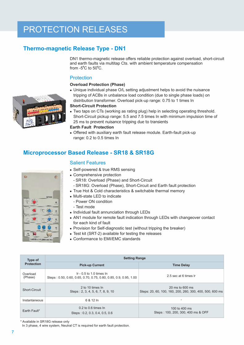
Microprocessor Based Release - SR18 & SR18G
Salient Features
�Self-powered
�Comprehensive protection
- SR18: and Short-Circuit
- SR18G: , Short and Earth fault protection
�True Hot & Cold characteristics
�Multi-state LED to indicate
- Power ON condition
- Test mode
�Individual fault annunciation through LEDs
�Test kit (SRT-2) available for testing the releases
�Conformance to EMI/EMC standards
& true RMS sensing
Overload (Phase)
Overload (Phase)
& switchable thermal memory
AN1 module for remote fault indication through LEDs with changeover contact
for each kind of fault
�Provision for Self-diagnostic test (without tripping the breaker)
-Circuit
�
2 to 10 times In
Steps : 2, 3, 4, 5, 6, 7, 8, 9, 10
20 ms to 600 ms
Steps : 20, 60, 100, 160, 200, 260 , 300, 400, 500, 600 ms
-
Type of
Protection
Overload (Phase)
Short-Circuit
Instantaneous
Earth Fault*
Setting Range
Pick-up Current Time Delay
Ir - 0.5 to 1.0 times In
Steps : 0.50, 0.60, 0.65, 0.70, 0.75, 0.80, 0.85, 0.9, 0.95, 1.00
0.2 to 0.6 times In
Steps : 0.2, 0.3, 0.4, 0.5, 0.6
100 to 400 ms
Steps : 100, 200, 300, 400 ms & OFF
6 & 12 In
2.5 sec at 6 times lr
* Available in SR18G release only
In 3 phase, 4 wire system, Neutral CT is required for earth fault protection.

Salient Features
� Test-kit for SR18G/SR18Gi with display
� Operates from 230V AC supply & generates single-phase voltage test signals
� Tests the release for
- Phase fault i.e. for overload, short-circuit and instantaneous protection
- Earth fault protection
� Test current multiples
- For phase faults: 2.5 In, 4.5 In, 6.5 In, 9.5 In, 11 In, 13 In
- For earth fault: 0.25 In, 0.35 In, 0.45 In, 0.55 In
� Five 7-segments LED display indicates the trip time (two places after decimal)
PROTECTION RELEASES
Test-kit UN-ES1
8
Microprocessor Based Release - with display SR18G
Salient Features
�
�
�
�
�
�
�
�
�
�
�
�
Self –powered &True RMS sensing
True Hot & Cold characteristics & switchable Thermal Memory
Unique 3 line O-LED display (Organic LED)
Offers comprehensive protection against Overload - Phase &
Neutral, Short-Circuit, Instantaneous, Earth Fault
Settable Overload delay
Settable Instantaneous setting with provision of “OFF” 2I t ON/OFF for Short-Circuit and Earth Fault protection
Individual Fault LED indication
Provision for Self-diagnostic test
Conformance to EMI/EMC standards
Testing through Test kit
Separate version with Zone Selective Interlocking (ZSI) - SR18Gi
with display
Pick-up current Time Delay
Type of
Protection
Overload (Phase)
Short-Circuit
Instantaneous
Earth fault*
Overload (Neutral)
Setting Range
0.2 to 30 sec at 6 times IrSteps : 0.2, 0.5, 1.5, 2, 3.5, 6, 12, 17, 30 sec
Same as Overload (Phase)
2l t ON = 0.02, 0.1, 0.2, 0.3, 0.4 sec
2l t OFF = 0.02, 0.1, 0.2, 0.3, 0.4, sec
2l t ON = 0.1, 0.2, 0.3, 0.4 sec
2l t OFF = 0.1, 0.2, 0.3, 0.4, 1 sec
Ir - 0.5 to 1.0 times InSteps : 0.50, 0.60, 0.65, 0.70, 0.75, 0.80, 0.85, 0.90, 0.95, 1
IN -50% to 200% times IrSteps : 50%, 100%, 150%, 200%
2 to 16 times InSteps : 2, 3, 4, 6, 8, 10, 12, 14, 16, OFF
2 to 10 times InSteps : 2, 3, 4, 5, 6, 7, 8, 9, 10
0.2 to 0.6 times InSteps : 0.2, 0.3, 0.4, 0.5, 0.6
-
*In 3 phase, 4 wire system, Neutral CT is required for earth fault protection

PROTECTION RELEASES
Salient Features
�Self-powered
�
�
�
�Multi-state LED to indicate
- Power ON condition
- Test mode
�Individual fault annunciation through LEDs
& True RMS sensing
Inbuilt Zone Selective Interlocking (ZSI)
Provision for Self-diagnostic test(without tripping the breaker)
& switchable Thermal Memory
Provision for
True Hot & Cold characteristics
� AN1 module for remote fault indication through LEDs
with changeover contact for each kind of fault
�Direct tripping of breaker-reliable tripping with minimum time delay
�Test kit available for testing the release (SRT-2)
�Realistic hot and cold curves which take into account integrated
heating effect
�Conformance to EMI/EMC standards
* In 3 phase, 4 wire system, Neutral CT is required for earth fault protection.
Microprocessor Based Release - SR21i
Ir - 0.5 to 1.0 times In
Steps : 0.50, 0.60, 0.65, 0.70, 0.75, 0.80, 0.85, 0.9, 0.95, 1.00
0.2 to 30 sec. at 6 times Ir
Steps : 0.2, 0.5, 1, 1.5, 2, 3.5, 6, 12, 17, 30 Sec
Pick-up Current Time Delay
Setting RangeType of
Protection
Overload(Phase)
Short-Circuit
Instantaneous
Earth Fault*
20 ms to 600 ms
Steps : 20, 60, 100, 160, 200, 260, 300, 400, 500, 600 ms
100 to 400 ms
Steps : 100, 200, 300, 400 ms & OFF
2 to 10 times In
Steps : 2, 3, 4, 5, 6, 7, 8, 9, 10
2 to 16 times In
Steps : 2, 3, 4, 6, 8, 10, 12, 14, 16, OFF
0.2 to 0.6 times In
Steps : 0.2, 0.3, 0.4, 0.5, 0.6
-
9
Test-kit SRT-2
Salient Features
�Test-Kit for SR18/SR18G/SR21i Releases
� Operates from 230V AC supply & generates single-phase voltage test signals
� Tests the release for
- Phase fault i.e. for overload, short-circuit and instantaneous protection
- Earth fault protection
� Test current multiples
- For phase faults: 2.5 In, 4.5 In, 6.5 In, 9.5 In, 11 In, 13 In
- For earth fault: 0.25 In, 0.35 In, 0.45 In, 0.55 In
� Five 7-segments LED display indicates the trip time
(two places after decimal)

PROTECTION RELEASES
Microprocessor-based, Communication-capable Release - SR71
Salient Features
� RMS sensing
� Offers comprehensive protection for overload, short-circuit,
instantaneous, earth fault and neutral overload
� High resolution backlit LCD display
�Intelligent Pre-trip alarm to prevent system shutdown
� Password protected settings and commands
� MODBUS RTU protocol
� LED indication for POWER ON, different faults and Pre-trip alarm
� 2 sets of storable protection settings
�
3 programmable contacts-1 for micro controller failure, 2 for basic
fault annunciation
� Auto-doubling features to prevent nuisance tripping2
� Selectable I t based current for short-time and earth fault zones
� Thermal reflectivity enables faster tripping on recurrent overloads
�
�
�
True
with intrinsic RS 485 port
Last 5 trips & 128 Event records with time & date stamping
Rating-plug for precise protection at lower load currents
Inbuilt Zone Selective Interlocking
Provision for Self-diagnostic test
Conformance to EMI/EMC standards
�
�4 relay contacts for indication of exceeding maximum demand, Pre-trip
alarm and control on breaker (closing and opening)
�
Screen
Abbreviation
Details Factory
Settings
Parameter
2l t OFF2l t ON
PICK-UP
TMS-Tr
PREALAR
THM-MEM
FUNC
PICK-UP
DELAY
PICK-UP
DELAY
DELAY
PREALAR2l t
COLDPIC
CP-DLY
FUNC
PICK-UP
FUNC
PICK-UP
DELAY
PREALAR2l t
COLDPIC
Current Settings (A), Ir = In x ....
Time Delay, Tr (sec) at 6 x Ir
Pre-trip Alarm Settings
Thermal Reflectivity
Function
Current Settings (A), In = Irx ....
Time Delay (sec)
Current Settings (A), Isd = In x ....
Time Delay, tsd (msec) at 10 x In
Pre-trip Alarm Settings2l t
Cold-load Pick-up
Cold-load Pick-up Delay
Function
Current Settings (A), Ii = In x ....
Function
Current Settings (A), Ig = In x ....
Time Delay (sec), tg
Pre-trip Alarm Settings2l t
Cold-load Pick-up
Overload
(Phase)
Neutral Fault
Short-Circuit
Instantaneous
Earth Fault
0.4 to 1.0 In steps of 0.05 In
0.5-1-2-4-6-12-18-24-30
0.5 to 0.95 Ir in steps of 0.05 Ir
ON / OFF
Enable / Disable
0.5-1.0
Same as 'Overload (Phase)'
2 to 10 In in steps of 0.5 In
20-100-200-300-400
20-100-200-300-400
0.5 to 0.95 Is in steps of 0.05 Is
ON / OFF
Enable / Disable
0.1 to 10 sec in steps of 0.1 sec
Enable / Disable
2 to 16 In in steps of 0.1 In
Enable / Disable2
0.1 to 0.6 in steps of 0.05 In for l t ON2
0.1 to 0.6 in steps of 0.01 In for l t OFF2
100 to 400 msecs in steps of 100 msec for l t ON2
0.1 to 5 sec in steps of 100 msec for l t OFF
0.5 to 0.95 Ig in steps of 0.05 Ig
ON / OFF
Enable / Disable
in 1.0 In
30 sec
0.95 Ir
OFF
1.0 Ir
30 sec
10 In
400 msec
400 msec
0.95 Is
Disable
0.1 sec
Enable
16 In
Enable
0.6 In
3 sec
0.95 Ig
OFF
Disable
Note: Both Protection Groups 1 & 2 carry the same factory settings. 10

ADDITIONAL PROTECTIONS
# Requires SR71-PM module
Under Current
Current Unbalance
Over Voltage #
Under Voltage #
Under Frequency #
Over Frequency #
Reverse Power #
Phase Sequence #
Breaker Failure
Maximum Demand
Exceed
i - Discrimination
Function
Current Setting (A) x In
Time Delay (secs)
Trip / Alarm
Function
Current Setting (A) x In
Time Delay (secs)
Function
Voltage Setting (V) Vs = Vn x ..
Time Delay (secs)
Reset Voltage
Trip / Alarm
Function
Voltage Setting (V) Vn x ..
Time Delay (secs)
Reset Voltage
Trip / Alarm
Function
Frequency Setting (Hz)
Time Delay (secs)
Drop Off Frequency
Trip / Alarm
Function
Frequency Setting (Hz)
Time Delay (secs)
Drop Off Frequency
Trip / Alarm
Function
Settings (kW)
Time Delay (secs)
Trip Alarm
Function
Settings
Time Delay (secs)
Trip / Alarm
Function
Time Delay (secs)
Function
Settings (kW)
Step
15% to 80% in steps of 5% In
1 to 255 in steps of 1 second
Either / Both
Enable / Disable
10% to 95% in steps of 5% In
1 to 10 in steps of 5 secs
Enable / Disable
105% to 150% in steps of 5% Vn
0.1 to 100 in steps of 0.1 secs
85% to 98% in steps of 1% Vs
Either / Both
Enable / Disable
45% to 65% in steps of 5% Vn
0.1 to 5 in steps of 0.1 secs
102% to 115% in steps of 1% Vs
Either / Both
Enable / Disable
45 to 50Hz for 50Hz in steps of 0.01Hz
57 to 60Hz for 60Hz in steps of 0.01Hz
0.1 to 100 secs in steps of 0.1 Second
0.02 to 0.10Hz in steps of 0.1Hz
Either / Both
Enable / Disable
50 to 55Hz for 50Hz in steps of 0.01Hz
60 to 62Hz for 60Hz in steps of 0.01Hz
o.1 to 100 secs in steps of 0.1 second
0.02 to 0.10Hz in steps of 0.1Hz
Either / Both
Enable / Disable
0.02 to 0.4 in steps of 0.01 Pn
1 to 100 in steps of 0.1 secs
Either / Both
Enable / Disable
123 - 132
0 to 5 in steps of 0.5 secs
Either / Both
Enable / Disable
0.05 to 2 secs in steps of 0.01 secs
Enable / Disable
40 kW - 1600 kW
10 kW - 1000 kW
Enable / Disable
Enable / Disable
PICK-UP
DELAY
MODE
FUNC
PICKUP
DELAY
FUNC
PICK-UP
DELAY
RSTSET
MODE
FUNC
PICK-UP
DELAY
RSTSET
MODE
FUNC
PICK-UP
DELAY
DRPOFF
MODE
FUNC
PICK-UP
DELAY
DRPOFF
MODE
FUNC
PICK-UP
DELAY
MODE
FUNC
PICK-UP
DELAY
MODE
FUNC
DELAY
FUNC
PICK-UP
DELAY
i -Discrimination
FUNC
0.8 In
1 second
Alarm
Disable
0.2 In
2.0 secs
Disable
1.2 Vn
5.0 secs
0.95 Vs
Alarm
Disable
0.6 Vn
1 second
1.02 Vs
Alarm
Disable
48.0Hz
59.0Hz
0.2 secs
0.1Hz
Alarm
Disable
52.0Hz
61.0Hz
0.2 secs
0.1Hz
Alarm
Disable
0.2 Pn
2.0 secs
Alarm
Disable
123
2 secs
Alarm
Disable
1.0 second
Disable
100 kW
10 kW
Disable
Disable
Parameter Screen
Abbreviation
Details Factory
Settings
11

# Requires SR71-PM module
Current
Voltage#
Frequency #
Power Factor #
Power #
Energy #
Harmonic-Current
Harmonic-Voltage #
Display
Imax
%Load
V
Vph-Vph
F
PF
kW
kVAr
kVA
kW
kWh
kVArh
kVAh
I1HAR
I2HAR
I3HAR
V1HAR
V2HAR
V3HAR
I
Maximum running Current per Phase
Percent Loading
Phase-Neutral
Phase-Phase
System Frequency
System Power Factor
Active Power per Phase and Total (kW)
Reactive Power per Phase and Total (kVAr)
Apparent Power per Phase and Total (kVA)
Maximum Demand (kW)
Total Active Energy (kWh)
Total Reactive Energy (kVArh)
Total Apparent Energy (kVAh)
R-Phase Current Harmonics
Y-Phase Current Harmonics
B-Phase Current Harmonics
R-Phase Voltage Harmonics
Y-Phase Voltage Harmonics
B-Phase Voltage Harmonics
High Resolution Backlit LCD
Phase, Earth and Neutral
Screen AbbreviationParameter Details
ADDITIONAL FEATURES Screen Abbreviation
In Multiplier
Protocol
Link used
Self-Diagnostic Test
Comunication Module (SR71-COM)
Power Supply Module (UN-PS)
Power Metering Module (SR71-PM)
Relay Module (SR71-REL)
Parameter
�
�
�
�
�
�
�
�
�
LED Indications
Auxiliary Supply
Digital Inputs
Output Relays
Rating Plug
Communication
Maintenance Indication
Event Records (128)
Trip Records
Testing
Supplementary Modules
No. of Storable Settings
Auxiliary Power ON
Overload
Short-Circuit
Instantaneous
Earth Fault
Neutral Fault
Trip
Alarm
24V DC
4 Nos.
3 Internal + 4 External Relays
240V AC / 5A, 30V DC / 5A (resistive load)
630-800-1000-1250-2000-3200-5000
MODBUS RTU
RS 4852I t based
Last 5 records with date and time stamping,
2
MODBUS RTU using RS 485
Input : 26V to 60V DC, 90 to 300V AC/DC Output : 24V DC
240V AC, 415V AC
4 Relay Outputs (Breaker OPEN, Breaker CLOSE, Pre
Trip alarm and MD Exceed)
Details
Pick-up, Alarm, Trip, Date, Time and Cause of Event,
voltage and current readings in all phases
METERING
12

Current Multiples ( x Ir)
Tri
p T
ime (
s)
1000
100
10
1
0.1
1 1.2 2 3 4 5 6 7 8 9 10 201.5
Overload (SR18/18G)
PROTECTION CHARACTERISTIC
Time-current (DN1)
Tri
p T
ime (
s)
Current Multiples ( x In)
1.05
1.2} Operating Limits
Thermal
Zone of Short-Circuit Operation (M1/M2)
25ms
DN1
Total Operating TimeMin. Impulsion Time
M1
M2
0.7 1 2 3 4 5 678910 20 304050 100 400 1000
10000
1000
100
10
0.01
0.40.3
0.2
0.1
13

0.2 0.6
0.4
1
0.1 0.1
0.1
0.01
100101
0.2
0.3
Current Multiples ( x In)
Tri
p T
ime (
s)
Earth Fault (SR18G)
PROTECTION CHARACTERISTIC
Short-Circuit (SR18/18G)
0.1
0.6
0.5
0.4
0.3
0.2
0.012 3 4 5 6 7 8 910 20 100
0.02
0.06
0.1
0.6
0.5
0.4
0.3
0.26
0.2
0.16
1
2 10
1
Tri
p T
ime (
s)
Current Multiples ( x In)
14

Overload (SR18G/ with display)SR18Gi
0.01
0.1
1
10
100
1000
10000
1 2 3 4 5 6 7 8 10
0.2s
0.5s
1s1.5s
2s
3.5s
6s
12s
17s
30s
trip time ±20%
Tri
p T
ime (
s)
Current Multiples (xIr)2
Short-Circuit I t ON (SR18G/ with display)SR18Gi
trip time ±20%
1 10
0.01
0.1
1
10
20ms
100ms
200ms
300ms
400ms
Tri
p T
ime
(s
)
Current Multiples (xIn)
PROTECTION CHARACTERISTIC
15

Instantaneous (SR18G/ with display)SR18Gi
20ms
100
0.01
1
trip time +40ms
1 10
Tri
p T
ime
(s
)
Current Multiples (xIn)
16
PROTECTION CHARACTERISTIC
2Short-Circuit I t OFF
(SR18G/ with display)SR18Gi
10
0.01
0.1
1
20ms
100ms
200ms
300ms
400ms
trip time 40ms �
1
Tri
p T
ime
(s
)
Current Multiples (xIn)

2Earth Fault I t OFF
(SR18G with display)/SR18Gi
0.1
1
200ms
300ms
400ms
100ms trip time ±40ms
10.1
Tri
p T
ime
(s
)
Current Multiples (xIn)
2Earth Fault I t ON
(SR18G with display)/SR18Gi
trip time ±20%
0.1 10
0.1
0.01
1
10
1
100ms
200ms
300ms
400ms
Current Multiples (xIn)
17
PROTECTION CHARACTERISTICTri
p T
ime (
s)

0.01
0.6
0.5
0.4
0.3
0.2
0.1
1 2 3 4 5 6 7 8 9 10 20 100
2 100.6
0.5
0.4
0.3
0.26
0.2
0.16
0.1
0.06
0.02
Tri
p T
ime (
s)
Current Multiples ( x In)
Short-Circuit (SR21i)
0.1
0.01
1 1.2 1.5 222
1
10
100
1000
10000
30
17
6
12
3.5
2.0
1.5
1.0
0.5
0.2
3 4 5 6 7 8 9 10
Overload (SR21i)
Current Multiples ( x Ir)
PROTECTION CHARACTERISTIC
18
Tri
p T
ime (
s)

1
0.1
0.01
0.1
0.2
0.3
0.4
0.2 0.6
1 10 100
Current Multiples ( x In)
Earth Fault (SR21i)
0.1
PROTECTION CHARACTERISTIC
Current Multiples ( x Ir)
Tri
p T
ime (
s)
1.5 2 3 4 5 6 9
0.01
10
100
1
1000
10,000
Overload Curve (SR71)
19
Tri
p T
ime (
s)
30 sec
24 sec
18 sec
12 sec
6 sec
4 sec
1 sec
0.5 secTolerance:Trip Time: ±20%
2 sec
Current Multiples ( x In)
Tri
p T
ime (
s)
1.5
2.0
3.0
4.0
6.0
8.0
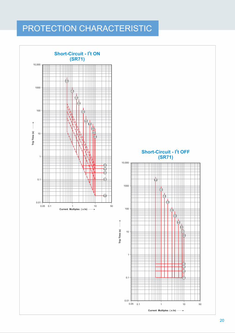
2Short-Circuit - I t OFF
(SR71)
0.01
0.1
10
100
1
1000
10,000
0.05 0.1 1 10 50
9.0
10.0
1.0
0.1
0.6
0.3
0.4
0.2
PROTECTION CHARACTERISTIC
2Short-Circuit - I t ON
(SR71)
Tri
p T
ime (
s)
Current Multiples ( x In)
0.3
0.2
0.1
0.4
0.02
0.6
1.0
1.5
2.0
3.0
4.0
6.0
8.0
9.0
10.0
0.01
0.1
10
100
0.05
1
1000
10,000
0.1 1 10 50
20

0.01
0.1
10
100
1
1000
10,000
0.05 0.1 1 10 50
2Earth Fault - I t ON
(SR71)
0.4
2.40.8
0.2
0.6
0.3
0.5
0.4s
0.1s
Tri
p T
ime (
s)
Current Multiples ( x In)
PROTECTION CHARACTERISTICTri
p T
ime (
s)
Current Multiples ( x In)
Instantaneous (SR71)
2.0
3.0
4.0
5.0
6.0
8.0
10.0
16.0
0.05 0.1 101 50
10.000
1000
100
10
1
0.1
0.01
21

PROTECTION CHARACTERISTIC
22
Tri
p T
ime (
s)
Current Multiples ( x In)
0.01
0.1
10
100
0.05
1
1000
10,000
0.1 1 10 50
2Earth Fault - I t OFF
(SR71)
0.3
0.4
0.5
0.4s
0.3s
0.2s
5.0
0.6
0.2
0.1s
1.0
0.3
0.4
0.5
5.0
0.6
0.2

WIRING DIAGRAM
23
For
SR
18G
i+D
& S
R21i re
lease (
P&
C u
nit)
SI, S
O
GI, G
O
G
i d
iscrim
ina
tio
n
i d
iscrim
ina
tio
n
Short
circuit i/p
& o
/p
Eart
h fault i/p
& o
/p
Eart
h
FC
A Lim
it s
witch(S
how
n in b
reaker
reset conditio
n)
R E
conom
y R
esis
tor
C11 L
imit s
witch o
pera
tes w
hen c
losin
g e
lectr
om
agnet is
held
on
C6 ‘S
erv
ice’ p
ositio
n m
icro
sw
itch for
withdra
wable
circuit b
reakers
(
show
n in ‘te
st’
positio
n)
Pro
tect
ion
&
Con
trol
Uni
t
1
Aux NC 2
Shu
nt
Rel
ease 3
Aux NC 4
Aux NO
5
Aux NC
6
Aux NO
7
Aux NC
8
Aux NO
9
Neu
tral
C.T
.
12
U/V
Rel
ease
13
Clo
sing
Pre
vent
er
14
Spr
ing
Cha
rgin
g
Indi
catio
n
15
Com
mon
faul
t
Indi
catio
n
16
Sep
arat
e
faul
t
Indi
catio
n
17
Shu
nt
trip
Indi
catio
n
18
Und
er
volta
ge
Indi
catio
n
19
Ele
ctric
al
anti-
pum
ping
20
Ele
ctric
Cha
rgin
g
Dev
ice
11
Clo
sing
Coi
l
10
(
((
((
((
((
((
16
A
15
41
42
4241
F5
25
5
((E
((50
(
((
((
((
((1
(( 8281
NC
T
((
B
E
CC
14
13
1211
109
86
2
75
MV
CP
(( DC
(( 40
43
Internal WiringOnly for DC
Internal Wiring
(
EA
/
EA
1
xB
((
81
82
As p
er
ord
er/
req
uire
me
nt
CA-1
C6
C11
R
73 (
(
(
(
(
(
75
74
70
72
71
B
Ele
ctrica
l a
nti-
pu
mp
ing
(
ECD
FH
((H
Mai
n
Circ
uit
Ref
no.
Load
xx
x
NR
Y
@
Po
we
r
For
SR
18G
/Gi+
D
SR18G/Gi+D((
AS
-
AS
+
Su
pp
ly
21
(+24V
DC
)
(-24V
DC
)
DN
1/S
R18
SR
18G
/SR
18G
/Gi+
DS
R2
1i/S
R7
1
The a
bove d
raw
ing is for
ED
O b
reakers
.
1)
For
MD
O/M
F v
ers
ions
R
ef no. 3, 10, 11
are
not applic
able
E
, B
, C
, D
, A
, 15 a
re a
pplic
able
only
in e
lectr
ical bre
akers
.
2)
For
EF
vers
ions
T
he r
ef. n
o. 12, 13, 14, 15, 16, 17, 18, 19, 20, 21 a
re p
rovid
ed a
s
per
custo
mer
requirem
ent.
3
) W
he
n u
sin
g A
N1
An
nu
ncia
tor
Mo
du
le w
ith
SR
18
G/1
8G
i (w
ith
dis
pla
y r
ele
ase
s)
A
) A
S+
& A
S-
alw
ays a
ppear
after
5,6
nos. of th
e S
IC.
B
) If 1
,2,3
,4,5
,6 n
os. of S
ICs a
re n
ot th
ere
, AS
+ &
AS
- w
ill a
ppear
firs
t.
C
) S
IC 1
3 a
nd 1
4 N
os. are
not offere
d in 3
P E
DO
and 3
P M
DO
sta
ndard
bre
akers
.

It is possible to provide “Mechanical Interlock” between two breakers of
the same or different ratings in vertical or horizontal configurations.
Mechanical interlock is available for ACBs upto 4000A by flexible cables
of 2 metres.
Mechanical Interlock
Mounted in place of normal trip push button. With this, ACB can be locked
in trip condition. For interlocking, LTPBs are offered in the following
combinations:
�4 different types of keys i.e. AA, BB, CC and DD suitable for
�Combination of L, M, N, LM and MN locks, which are suitable for
�Combination of K, L, M, N, KL, LM and MN locks, which are suitable for
�Combination of J, K, L, M, N, JK, KL, LM and MN locks, which are
suitable for
2 I/C & 1 B/C
schemes
3 I/C & 2 B/C schemes
4 I/C & 3 B/C schemes
5 I/C & 4 B/C schemes
Lockable Trip Push
Button (LTPB)
Type
Locking in Isolated Position (LIP)
The facility of locking the ACB in Isolated position is available in Drawout
ACBs. This is useful to achieve interlocking between Main & Standby
source. Similar lock is available as LOCK IN ANY POSITION.
Door Interlock
This ensures:
�Unless the panel door is closed, breaker cannot be racked in or out
�Unless the breaker is in Isolated Position, it is not possible to open the
panel door
Racking Interlock
This ensures that breaker cannot be racked in/out unless the ACB is in
tripped/open condition.
Door
Interlock
Racking
Interlock
Locking in
‘Isolated’
Position
View of the Cradle
Data
ACCESSORIES
24

ACCESSORIES
DataType
Separate indication of tripping due to overload, short-circuit
and earth faults.
For release type DN1, this is provided by micro-switch C1
& C2 (C2 fitted inside release)
�
C2
Remote indication of tripping due to overload, short-circuit
and earth faults.
�
�Individual fault indication provided by three separate LEDs for
- Long time faults
- Short time fault/instantaneous fault
- Earth fault
- One potential free contact rated 5A at 230V AC available for
each type of fault
�Flush mounting on panel (H-W-D=92mm x 46mm x 105mm)
�Operating voltage: 240V AC
Can be used with releases type SR18/SR18G/SR21i/SR18G
& SR18Gi with display
AN1-Annunciator Module
C5
Indication for operation of shunt release or undervoltage
release.
Provided by micro-switch C5 fitted on the shunt release
� or
undervoltage release
Common indication of tripping due to overload, short-circuit
and earth faults.
Provided by micro-switch C1 fitted inside the ACB
Available as an option in all releases
�
�
C1
25

ACCESSORIES
�
time delay
Notes: When under voltage
release is provided, the ACB can
be closed only when supply is
available to the under voltage
release.
Type MV With no intentional
Data
�
breaker
�Shunt release coil is short time
rated and is disconnected from
the circuit by an auxiliary
contact when the ACB trips
(Refer to wiring diagram)
�Low power consumption
� Two types available:
- EA for DC application
- EA1 for AC application
For remote tripping of the Shunt Release
Under Voltage Release
Type Technical Data
Two combinations available:
�2 NO + 2 NC
�6 NO + 6 NC
Auxiliary Contacts Electricalcircuit
Resistive
Non-resistive
Voltage(V)
Rated current (A)
# L/R = 15 ms with 2NO or 2NC contacts in series
161.2
161.0 #
24 to 415 AC250V DC
24 to 415 AC250V DC
Closing Release
Closing release remotely closes
the circuit breaker if the
mechanism spring is already
charged.
Spring Charging Motor Electrical charging device
automatically charges the
mechanism spring of the
circuit-breaker. After circuit-
breaker closing, the geared
motor immediately recharges
the closing spring. Thus
instantaneous reclosing of
the circuit-breaker is possible
following opening operation.
Rated
operational
voltage
(Ue)
Power
consumption
Range
of
operation
240V AC
110V DC
220V DC
320 VA
154 W
85-110%
Ue
Rated
voltage
(Us)
Power
consumption
Range
of
operation
110V, 50Hz240V, 50Hz220V, 60Hz
Pick-up Hold-on
110V DC, 220V DC24V, 30V,48V DC
320 VA
300 W
50 VA
50 W
85-110%
Us
26
Note : Other voltages available on request
Type
of
Release
Power
consum-
ption at
pick-up
Operation
Limit
EA1
800 VA
800 VA
800 VA
10-130%
V
EA
Nominal VoltageUse (V)
24V DC
48V DC
110 DC
220 DC
110 AC
240 AC
415 AC
32 W
125 W
45 W
30 W
Parameter Specification
Nominal voltage
Pick up (V)
Drop off (V)
VA Consumption
80% Ue
35-65% Ue
Pick up - 23 VAHold on - 8.5 VA
Watt loss 6 W
240V & 415V 50Hz AC, 220V & 415V 60Hz AC,
& 24V DC
65-130%
V
16
for Metallic Components
To Remove
Arc Chute
DoorBezel2
00
min
10
0 m
in
9
340 min
20 min
for Insulating Sheet
14
0 m
in
7
27
38
5
33
22
30 35
20230
301
4052.6 min
86
27
54
10
68.8
25
6
Earthing Terminal
2 Holes-Ø6.3
216
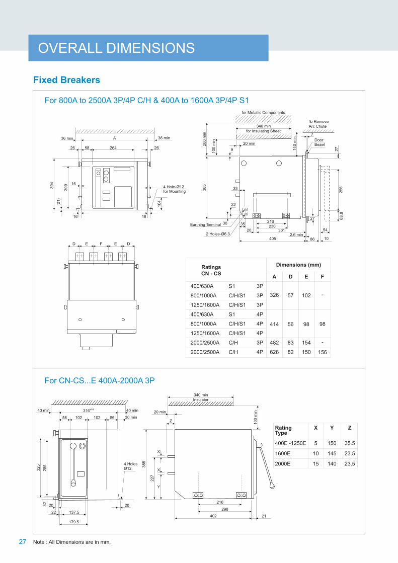
OVERALL DIMENSIONS
Note : All Dimensions are in mm.
Rating Type
400E -1250E
1600E
2000E
X
5
10
15
Y
150
145
140
FE DD E
40 min 40 min+1.0316
58 102 102 56
32
5
28
5
20
22 137.5
179.5
32
20
4 HolesØ12
38
5
X
X
Y
22
7
20 min
Z
340 minInsulator
10
0 m
in
216
298
402 21
Dimensions (mm)Ratings
CN - CSA
326
414
482
628
D
57
56
83
82
E
102
98
154
150
F
-
98
-
156
400/630A
800/1000A
1250/1600A
400/630A
800/1000A
1250/1600A
2000/2500A
2000/2500A
3P
3P
3P
4P
4P
4P
3P
4P
S1
C/H/S1
C/H/S1
S1
C/H/S1
C/H/S1
C/H
C/H
Fixed Breakers
For 800A to 2500A 3P/4P C/H & 400A to 1600A 3P/4P S1
For CN-CS...E 400A-2000A 3P
27
Z
35.5
23.5
23.5
30 min
(21
)
01
4
30
9
39
4
i36 m n
26
A 36 min
26458 26
1616
4 Hole- Ø12for Mounting

3200D/4000A C 3P
3200D/4000A C 4P
A
628
830
Rating CN-CS B
636
838
D
112
112
E
202
202
F
-
202
Dimensions (mm)
For 3200D/4000C 3P/4P
OVERALL DIMENSIONS
Fixed Breakers
Bezel Fixing Plan for all Fixed Breakers
BezelDoor Drilling for
Bezel Fixing PlanDoor Cutout
Hinge
32
5
A
11 min 59 294 15 min
Hinge
Terminal
400 to 2000E, 800/1000/1250/1600C/H &
400/630/800/1000/1250/1600S1
2000/2500C/H
332
36
3
5.5
305
10112 Holes- 4Ø
11
2112
112
Terminal Connections
Note:
A = 89 for 4000C/3200D
A = 91 for other fixed ACBs
30
15
12.5
25
50
2 Holes- 13Ø
30
15
2525 25
100
3 Holes- 13Ø
25
Terminal for800/1000 S1
Terminal for 1600 S1800/1000 H, 1250/
1600 C/H,2000/2500 C/H
Terminal for400/630 S1
Terminal for 800 C,1000 C &1250 S1
# 35.5 : For 1250S1
15
15
23.5
22
7
14
0
5
5
35.5
22
7
15
0
10
10
23.5
22
7
14
5
#
8
8
35.5
22
7
14
7
30
B
2645826
50
9
39
4
30
92
1
16
D E E
A
F D
4
26
36 min
26
4
36 min
4 Holes- 12 for Mounting Ø
15
15
28
7
17
3.5
71
44420
230
140
2.6min
85 10
54
68
.82
56
27
Earthing Terminal
2 Holes-ø6.3
50
3
25
71
10
0m
in
20
0m
in
14
0m
in
7DoorBezel
to RemoveArc Chute
for Metallic Components
For Insulating Sheet16min
16
10
2
16
27
33
22
6 Holes-Ø14
3015
160
50
70
27
Rear View
Note : All Dimensions are in mm. 28
Terminal Connections
Terminal for 3200D / 4000C
356 min
50
For 3200D/4000C

Drawout Breakers
For 800A to 2500A C/H, 3200A H2/H1, 4000A H2/H, 400A to 3200A S1 3P/4P
D E F E D
64.5
Earthing Terminal
Dimensions (mm)Ratings
CN - CS
400/630/800/1000A
2000A
1250/1600A
400/630/800/1000A
2000A
1250/1600A
2000/2500A
2500/3200A
2000/2500A
2500/3200A
3200A
4000A
3200A
4000A
3P
3P
4P
4P
3P
4P
3P
3P
4P
4P
3P
4P
3P
4P
A
399
487
D
97.5
96.5
E
102
98
F
-
98
C/H/S1
S1
C/H/S1
S1
C/H
S1
C/H
S1
H2/H1
H2/H
H2/H1
H2/H
C/H/S1
C/H/S1
555
701
701
909
123.5
122.5
148.5
151.5
154
150
202
202
-
156
-
202
Note : All Dimensions are in mm.
OVERALL DIMENSIONS
25
65
5
40
15
30
8.5
22
1.5
22
1.53
08
.5
15
15
22
1.53
08
.5
605
40
10
30
8.5
22
1.5
Terminal for
for 3200S1
Terminal for
3200H2/H1
& 4000H2/H
Terminal for
1250/1600/2500C/H
& 800/1000/2000H,
1600/2000S1
Terminal for
400/630/800/1000/1250
S1 & 800/1000C, 2000C,
2500S1
29
A
122
26494.5
40
4
6
199.5
46
8
for Metallic Components
for Insulating Sheet380 min
40 max
64.5
39
7.5
46M 10
4
6
538
10
0
min Door
Bezel
Service Position
51 Test Position
75 Isolated Position
17.5 min.
18.9 max.
8.9 min.
18 245
20
7428 1
60
26
20
0 m
in
7
(10) 54
68
.82
56

54
15 15
67
Terminal Connections5000C/6300C
28
17.5
40 50 40 43.5
63
217
8 Holes- 14Ø
Terminal Connections4000C
6 Holes- 14Ø25 25 25 25 25
160
17.5
50
25
12
.5
Drawout Breakers
Flat Terminal Connections
800 - 1000C & 400 - 1250S1 2000C
2500C/H & 2000H 2500S1
For 3200D/4000/5000/6300C 3P/4P
20
106
3333
43
67
12
6 Holes- 14Ø
20
106
33
43
67
12
6 Holes 14-Ø
38
62
12.5
4 slots
8.5 x 9.5
25
10.2
38
58.4
8.5
50
6 Holes 14-Ø
160
25 25 25 25 2517.5
25
507
0
12
.5
19
63
4 Slots
8.5 x 9.5
25
10.2
38
58
.4
8.5
800 - 1000H, 1250/1600C/H & 1600 - 2000S1
6 Slots
8.5 x 9.5
100
30
38
58
.4
10.2
8.5
30
20
3200S1 3200H2/H1 & 4000H2/H
106
6 Holes- Ø14
OVERALL DIMENSIONS
33 33 33
2012
160
20
6060
46
70
12
6 Holes- Ø14
Terminal Connections 3200D
A D E
3200D/4000C
3200D/4000C
5000A/6300A
5000A/6300A
3P
4P
3P
4P
711
913
913
1182
155.5
156.5
187.5
187.5
200
200
269
269
RatingsDimensions (mm)
Note : All Dimensions are in mm.
36
8
25
6
36
8
25
6
Terminal for4000A C
Terminal for5000/6300A C
30
1
A
124
96.5 264
6
199.5
40
4
D E E E D
58
3
42
64.5 Earthing Terminal
For Metallic Components
for Insulating Sheet
40max
102
10
0m
in
20
0m
in
Isolated Position
Test Position
Service Position
26
46
73
68
25
6
M 1
0
105
5
615
17.5min
18.9max
245
8.9min
18
20 2
8
(74
) 16
0
400min75
51
FRONT VIEW
REAR VIEW
SIDE VIEW
28
5
Terminal for 3200D
DoorBezel
10 54
68.8
25
6
7

OVERALL DIMENSIONS
For Horizontal Mounting of all Draw-out Breakers
Bezel Fixing Plan for all Draw-out Breakers
For 3200D/4000C/5000C/6300C 3P/4P
25
50
108.5
184.5
25
10 Holes- 11Ø592
552
Door Cutout
Hinge
A20.5 min 294 5 min
Hinge
Base ofCradle
1
41
2
5.5
6 Holes- 4Ø
19
92
24
305 332
45
0
37
24
Front
48120
64.1
*G
107.5 367.5 40
24
10 Holes- 11Ø
For 400A to 3200A C/H/ S1 3P/4P 3200 H2/H1, 4000 H2/H 3P/4P
800A - 1600A
400A - 2000A
800A - 1600A
400A - 2000A
2000 / 2500A
2000 / 2500A
2500 / 3200A
2500 / 3200A
3200A
3200A
4000A
4000A
3P
3P
4P
4P
3P
4P
3P
4P
3P
4P
3P
4P
C/H
S1
C/H
S1
C/H
C/H
S1
S1
H2 / H1
H2/ H1
H2/ H
H2 / H
280.3
280.3
368.3
368.3
436.3
582.3
436.3
582.3
582.3
790.3
582.3
790.3
RatingsG
(mm)Type
Mounting Details
Note : All Dimensions are in mm.
Door Drillingfor Bezel Fixing Plan
Bezel
31
3200D/4000C
3200D/4000C
5000C/6300C
5000C/6300C
Ratings CN-CSDimensions
A
711
913
913
1182
A
Note: For 3200A D 3P/4P, 4000A C 3P/4P, 5000C/6300C 3P/4P ACB, A=81.5For other Drawout Breakers A=79.5

800 - 1000C 1250 - 1600C/H& 800/1000H
2000C 2500C/H& 2000H
80 80 801
510
10
15
30
8.5
22
1.5
80
Rear Side
25
25
25
12.5 25
10
0
12
.5
20
10
6 33
12 43
12.5
12.5
50
25
25
2 Holes-Ø14
63
15
16.5
12.5 30
16
.5
33
3200 H0/H1/H2& 4000 H0/H/H2
110
15
12.5 251
60
25
25
25
25
25
17.5
OVERALL DIMENSIONS
Terminals
Note : 1) All Dimensions are in mm. 2) Consult us for other Terminal Orientations.
Horizontal Terminals
Side View Rear View
Vertical Terminals
Ratings M N P Q R S T U V W X
400-1250 S1 & 800-1000 C
1600-2000 S1 & 1250-1600 C/H
800-1000 H
2500 S1/ C/H
2000 H
3200 S1
2000 C
10.2
20
20
20
30
38
40
40
40
60
20
20
20
20
20
25
25
40
40
40
29.2
29.2
29.2
33.5
33.5
5
5
22.5
7.5
7.5
9
9
14
14
14
65
65
80
80
80
95
95
110
110
110
10
10
15
15
15
58.4
80
80
80
120
V
U
O P4 Holes T-Ø
NM
R
38
7.5 X
22
1.5
30
8.5
S
Top
W
32
40
3 Holes-Ø14 4 Holes-Ø14 6 Holes-Ø146 Holes-Ø14

S W
U 60.0
Q P6 Holes - ØT Top
RNN
M
387.5 X
30
8.5
22
1.5
Side ViewRear View
OVERALL DIMENSIONS
Terminals
Vertical Terminals 3200 H2/H1, 4000 H2/H
Ratings M N P Q R S T U V W X
3200 H2/ , 4000A H2/HH1 30 50 45 40 22.5 95 14 105 135 15 160
The dimensions for and are as under:3200 H2/H1 4000 H2/H
Note : 1) All Dimensions are in mm. 2) Consult us for other Terminal.
V
33

Please contact any of the training centres for participation and detailed training programme schedule.
So gain the advantage and go the extra mile with:�
�
�
�
The typical training programmes cover:
�
�
�
�
�
22 courses on contemporary topicsCourses applicable to all switchgear brandsTraining Centers in Pune, Lucknow, Coonoor, Vadodara, Delhi & KolkataBlend of theory and practical experience
Low Voltage & Medium Voltage Switchgear
Switchboard Electrical Design
AC Drives & Building Management Solutions
Protective Relays, Earthing, Reactive Power Management & Harmonics
Energy Conservation & Management
Aimed at maximizing productivity, conserving energy, minimizing costs and enhancing safety, our Electrical
& Automation training programmes have benefitted over 1.35 Lakh professionals in the last 28 years. These
training programmes are highly beneficial as they provide right exposure and impart knowledge on
selection, installation, maintenance and testing of Electrical & Automation Products.
Pune
Larsen & Toubro LimitedSwitchgear Training Centre, T-156/157, MIDCBhosari, Pune - 411 026Tel: 020 2712 0037 / 2712 0653 Fax: 020 2712 2933 E-mail: [email protected]
Lucknow
Larsen & Toubro LimitedSwitchgear Training Centre, C - 6 & 7, UPSIDCP. O. Sarojininagar, Lucknow - 226 008Tel: 0522 247 6015 / 97944 54455 Fax: 0522 247 6015 E-mail: [email protected]
Coonoor
Larsen & Toubro LimitedSwitchgear Training Centre, Ooty-Coonoor Main RoadYellanahalli P.O., The Nilgiris - 643 243Tel. : 0423 251 7107Fax : 0423 251 7158E-mail: [email protected]
Vadodara
Larsen & Toubro LimitedSwitchgear Training CentreBehind L&T Knowledge City, Near Village Ankhol, Vadodara - 390019Tel: 0265 2457805E-mail: [email protected]
Delhi
Larsen & Toubro LtdSwitchgear Training Centre32, Shivaji Marg,Near Motinagar Metro Station,New Delhi – 110015 Tel: 011 41419515 / 41419695 /41419500Fax: 011 41419600E-mail: [email protected]
Kolkata
Larsen & Toubro LimitedSwitchgear Training Centre4th Floor, 3B, Shakespeare Sarani, Kolkata-700071Tel: 033 44002151E-mail: [email protected]

SP 50437 R5
Khairasol, Degaul AvenueDurgapur 713 212Tel: 0343-2540448 / 2540449 / 2540443Fax: 0343-2540442e-mail: [email protected]
5, Milanpur Road, Bamuni MaidanGuwahati 781 021Tel: +91 8876554410 / 8876554417Fax: 361-2551308e-mail: [email protected]
II Floor, Vasantha Chambers5-10-173, Fateh Maidan RoadHyderabad 500 004Tel: 040-67015052Fax: 040-23296468e-mail: [email protected]
Monarch Building, 1st FloorD-236 & 237, Amrapali MargVaishali NagarJaipur 302 021Tel: 0141-4385914 to 18Fax: 0141-4385925e-mail: [email protected]
Akashdeep Plaza, 2nd FloorP. O. GolmuriJamshedpur 831 003JharkhandTel: 0657-2312205 / 38Fax: 0657-2341250e-mail: [email protected]
Skybright Bldg; M. G. RoadRavipuram Junction, ErnakulamKochi 682 016Tel: 0484-4409420 / 4 / 5 / 7Fax: 0484-4409426e-mail: [email protected]
3-B, Shakespeare SaraniKolkata 700 071Tel: 033-42005982Fax: 033-22821025 / 7587e-mail: [email protected]
A28, Indira Nagar, Faizabad Road Lucknow 226 016Tel: 0522-4929905 / 04Fax: 0522-2311671e-mail: [email protected]
No: 73, Karpaga Nagar, 8th StreetK. PudurMadurai 625 007Tel: 0452-2567405 / 2561068 / 2561657Fax: 0452-2567552e-mail: [email protected]
Product improvement is a continuous process. For the latest information and special applications, please contact any of our offices listed here.
Electrical Standard Products (ESP) Offices:
HEAD OFFICEL&T Business Park,Tower 'B' / 3rd FloorSaki Vihar Road, PowaiMumbai 400 072Tel: 022-67053229 Fax: 022-67051112e-mail: [email protected]
BRANCH OFFICES501, Sakar Complex I Opp. Gandhigram Rly. Station Ashram RoadAhmedabad 380 009Tel: 079-66304006-11Fax: 079-66304025e-mail: [email protected]
38, Cubbon Road, P. O. Box 5098Bengaluru 560 001Tel: 080-25020100 / 25020324Fax: 080-25580525e-mail: [email protected]
131/1, Zone IIMaharana Pratap NagarBhopal 462 011Tel: 0755-3080511 / 05 / 08 / 13 / 17 / 19 Fax: 0755-3080502e-mail: [email protected]
Plot No. 559, Annapurna ComplexLewis RoadBhubaneswar 751 014Tel: 0674-6451342 / 2436690 / 2436696Fax: 0674-2537309e-mail: [email protected]
Aspire Towers, 4th FloorPlot No. 55, Phase-IIndustrial & Business ParkChandigarh-160 002Tel: 0172-4646840 / 41 / 42 / 46 / 53Fax: 0172-4646802Email: [email protected]
L&T Construction CampusTC-1 Building, II FloorMount-Poonamallee RoadManapakkamChennai 600 089Tel: 044-2270 6800Fax: 044-22706940e-mail: [email protected]
67, Appuswamy RoadPost Bag 7156 Opp. Nirmala CollegeCoimbatore 641 045Tel: 0422-2588120 / 1 / 5Fax: 0422-2588148e-mail: [email protected]
L&T Business Park,Tower 'B' / 5th FloorSaki Vihar Road, PowaiMumbai 400 072Tel: 022-67052874 / 2737 / 1156Fax: 022-67051112e-mail: [email protected]
12, Shivaji NagarNorth Ambajhari RoadNagpur 440 010Tel: 0712-2260012 / 6606421Fax: 2260030 / 6606434e-mail: [email protected]
32, Shivaji Marg P. O. Box 6223New Delhi 110 015Tel: 011-41419514 / 5 / 6Fax: 011-41419600e-mail: [email protected]
L&T House P. O. Box 119 191/1, Dhole Patil RoadPune 411 001Tel: 020-66033395 / 66033279Fax: 020-26164048 / 26164910e-mail: [email protected]
Crystal Tower, 4th Floor, G. E. RoadTelibandhaRaipur - 492 006Tel: 0771-4283214e-mail: [email protected]
3rd Floor Vishwakarma ChambersMajura Gate, Ring RoadSurat 395 002Tel: 0261-2473726Fax: 0261-2477078e-mail: [email protected]
Radhadaya ComplexOld Padra RoadNear Charotar SocietyVadodara 390 007Tel: 0265-6613610 / 1 / 2Fax: 0265-2336184e-mail: [email protected]
Door No. 49-38-14/3/2, 1st floor,NGGO's Colony, Akkayyapalem,Visakhapatnam - 530 016Tel: 0891-2791126 / 2711125Fax: 0891-2791100Email: [email protected]
Larsen & Toubro Limited, Electrical Standard Products
Powai Campus, Mumbai 400 072
Customer Interaction Center (CIC)
BSNL / MTNL (toll free) : 1800 233 5858 Reliance (toll free) : 1800 200 5858
Tel : 022 6774 5858, Fax : 022 6774 5859
E-mail : [email protected] / Website www.Lntebg.com
Registered Office: L&T House, N. M. Marg, Ballard Estate, Mumbai 400 001, INDIA CIN: L99999MH1946PLC004768