Embed Size (px)
Citation preview
AiM User Manual
ECU Bridge
Release 1.09
1
1 Introduction
ECU Bridge has been designed and developed by AiM to allow SmartyCam to connect to your vehicle ECU, sample and show the data out coming from it. On www.aim-sportline.com, area download, ECU connection you find the list of supported ECU. ECU Bridge manages the three most popular communication protocols: CAN, RS232 and K Line. ECU Bridge samples but does not record data.
ECU Bridge is available in two versions:
• ECU Bridge with OBDII connector (K Line and CAN protocols) for direct connection with the vehicle ECU: recommended for stock ECUs
• ECU Bridge free wires (CAN/RS232 protocols) useful for connection with aftermarket ECUs
This user manual explains how to install, connect and configure ECU Bridge.
Please note: to always keep you ECU Bridge updated AiM strongly recommends to periodically check AiM www.aim-sportline.com, area download software and/or firmware and download the latest versions of ECU Bridge firmware and Race Studio 2 Configuration software.
2
2 Kits and part numbers
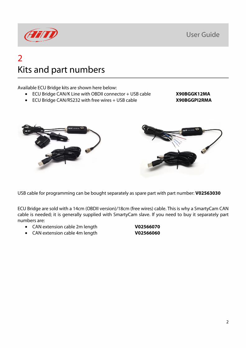
Available ECU Bridge kits are shown here below:
• ECU Bridge CAN/K Line with OBDII connector + USB cable X90BGGK12MA
• ECU Bridge CAN/RS232 with free wires + USB cable X90BGGPI2RMA
USB cable for programming can be bought separately as spare part with part number: V02563030
ECU Bridge are sold with a 14cm (OBDII version)/18cm (free wires) cable. This is why a SmartyCam CAN cable is needed; it is generally supplied with SmartyCam slave. If you need to buy it separately part numbers are:
• CAN extension cable 2m length V02566070
• CAN extension cable 4m length V02566060
3
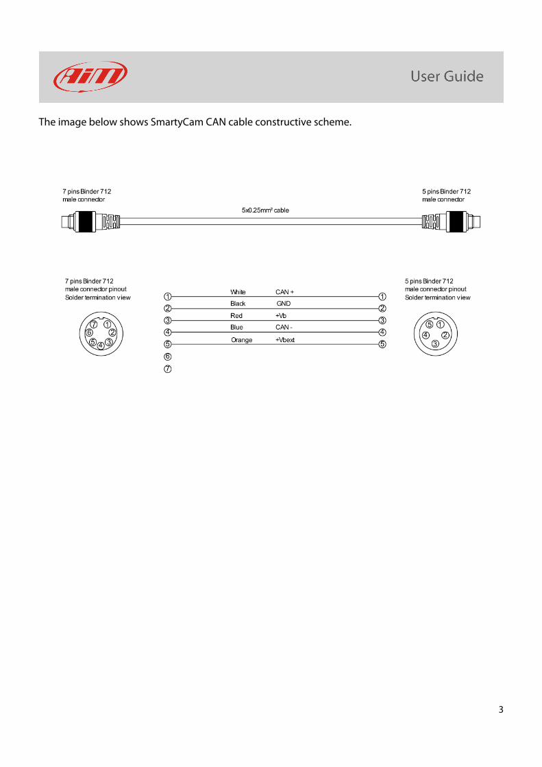
The image below shows SmartyCam CAN cable constructive scheme.
4
3 Installation, power and connections
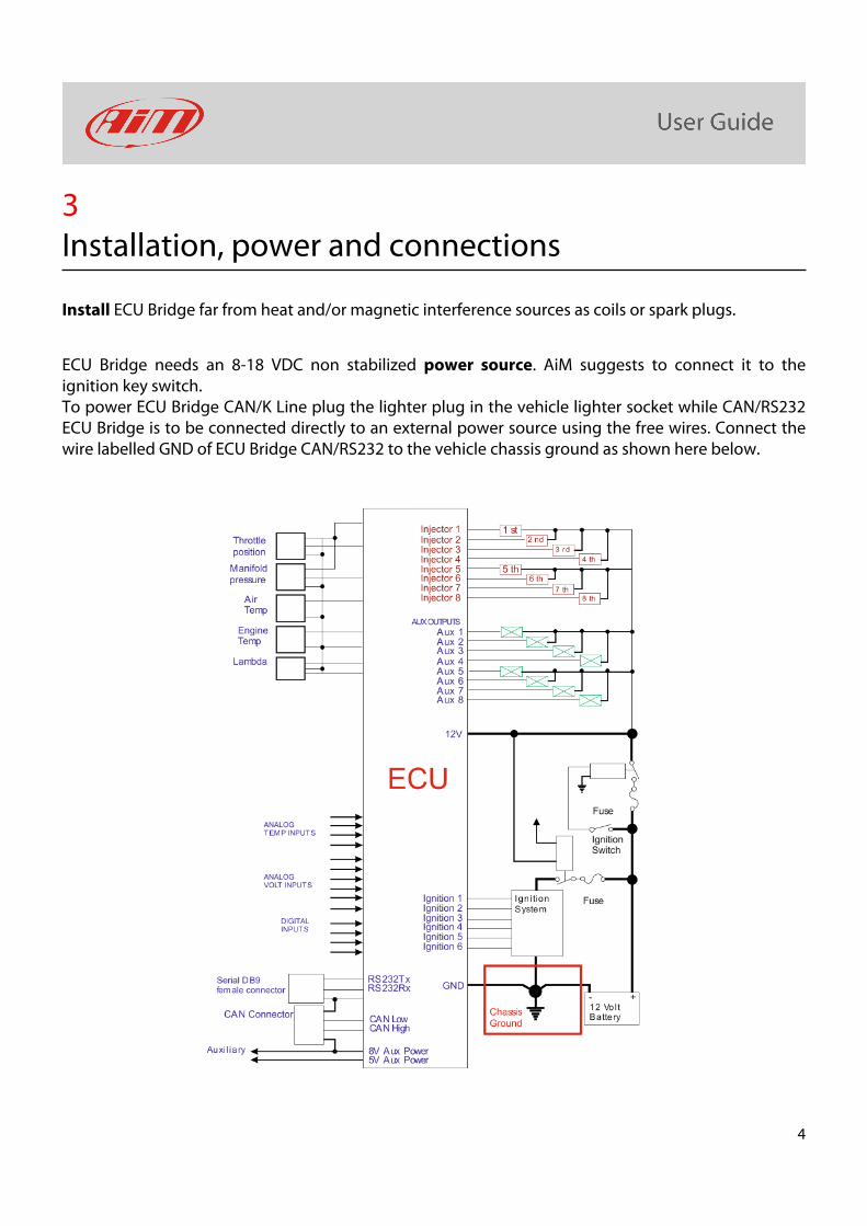
Install ECU Bridge far from heat and/or magnetic interference sources as coils or spark plugs.
ECU Bridge needs an 8-18 VDC non stabilized power source. AiM suggests to connect it to the ignition key switch. To power ECU Bridge CAN/K Line plug the lighter plug in the vehicle lighter socket while CAN/RS232 ECU Bridge is to be connected directly to an external power source using the free wires. Connect the wire labelled GND of ECU Bridge CAN/RS232 to the vehicle chassis ground as shown here below.
5
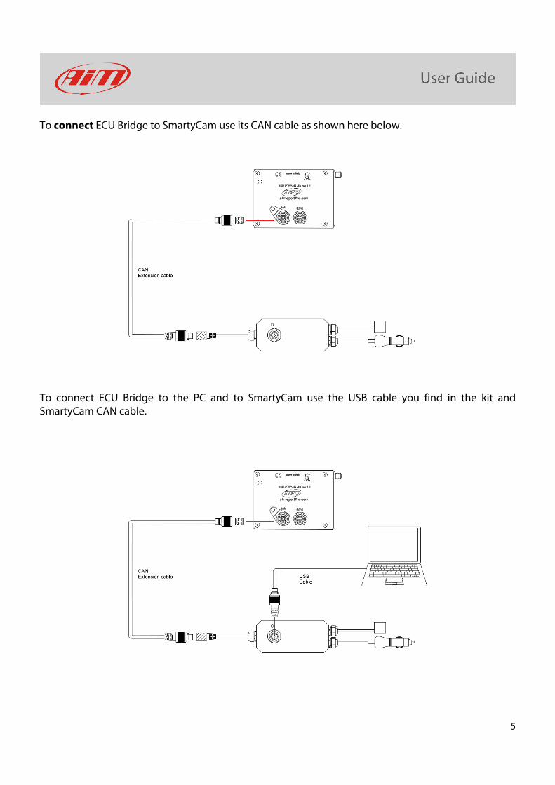
To connect ECU Bridge to SmartyCam use its CAN cable as shown here below.
To connect ECU Bridge to the PC and to SmartyCam use the USB cable you find in the kit and SmartyCam CAN cable.
6
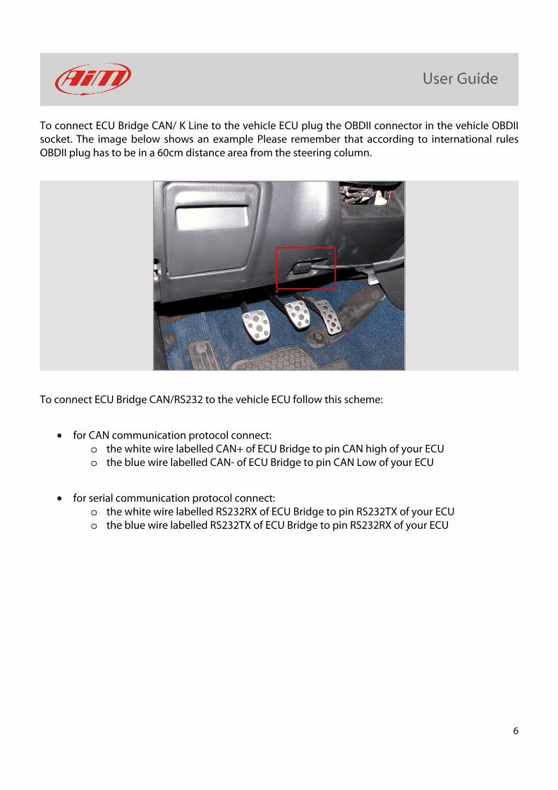
To connect ECU Bridge CAN/ K Line to the vehicle ECU plug the OBDII connector in the vehicle OBDII socket. The image below shows an example Please remember that according to international rules OBDII plug has to be in a 60cm distance area from the steering column.
To connect ECU Bridge CAN/RS232 to the vehicle ECU follow this scheme:
• for CAN communication protocol connect: o the white wire labelled CAN+ of ECU Bridge to pin CAN high of your ECU o the blue wire labelled CAN- of ECU Bridge to pin CAN Low of your ECU
• for serial communication protocol connect: o the white wire labelled RS232RX of ECU Bridge to pin RS232TX of your ECU o the blue wire labelled RS232TX of ECU Bridge to pin RS232RX of your ECU
7
4 Setup with Race Studio 2
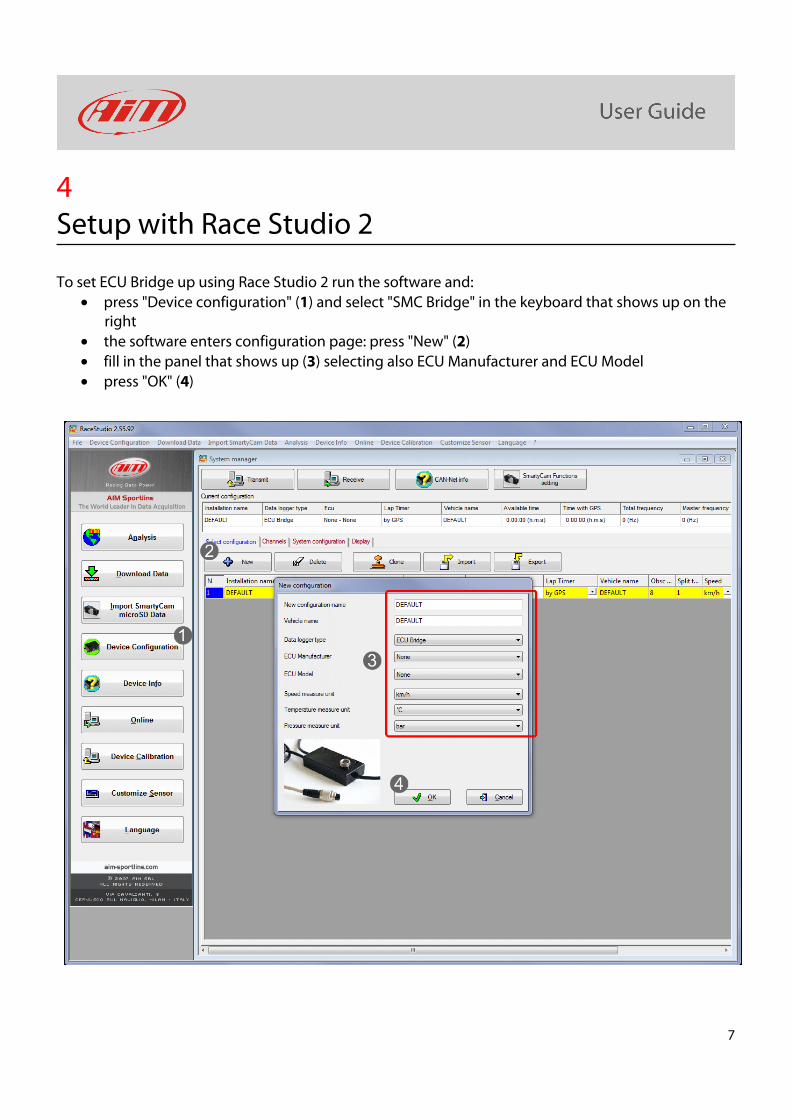
To set ECU Bridge up using Race Studio 2 run the software and:
• press "Device configuration" (1) and select "SMC Bridge" in the keyboard that shows up on the right
• the software enters configuration page: press "New" (2)
• fill in the panel that shows up (3) selecting also ECU Manufacturer and ECU Model
• press "OK" (4)
8
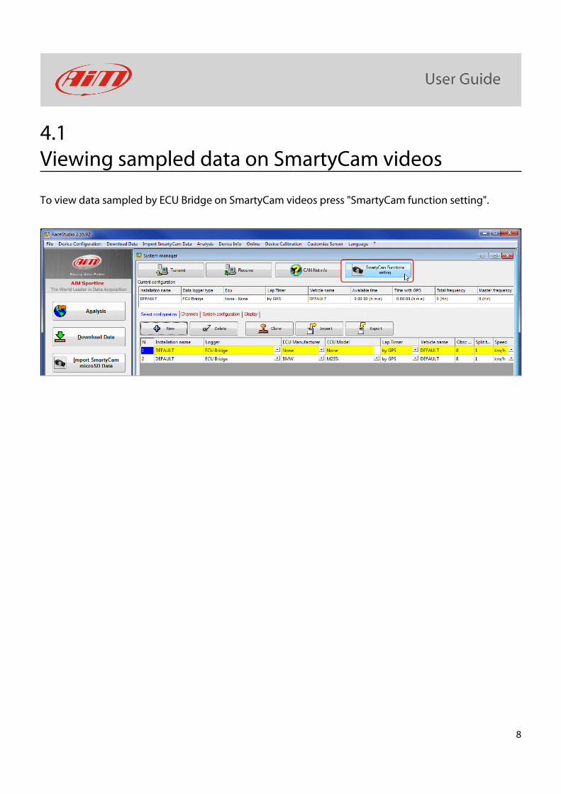
4.1 Viewing sampled data on SmartyCam videos
To view data sampled by ECU Bridge on SmartyCam videos press "SmartyCam function setting".
9
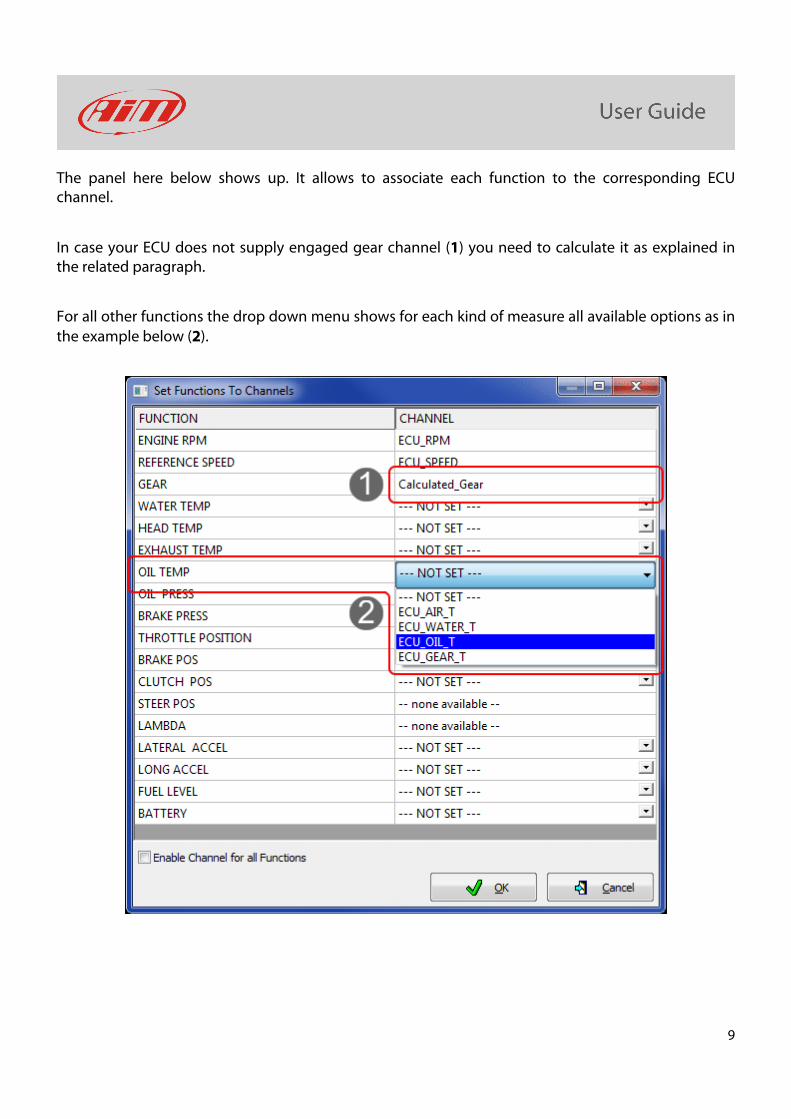
The panel here below shows up. It allows to associate each function to the corresponding ECU channel.
In case your ECU does not supply engaged gear channel (1) you need to calculate it as explained in the related paragraph.
For all other functions the drop down menu shows for each kind of measure all available options as in the example below (2).
10
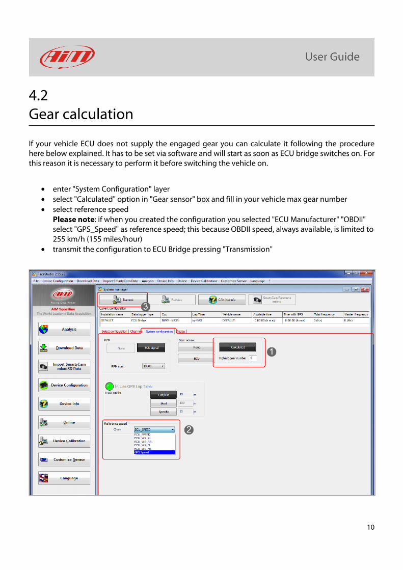
4.2 Gear calculation
If your vehicle ECU does not supply the engaged gear you can calculate it following the procedure here below explained. It has to be set via software and will start as soon as ECU bridge switches on. For this reason it is necessary to perform it before switching the vehicle on.
• enter "System Configuration" layer
• select "Calculated" option in "Gear sensor" box and fill in your vehicle max gear number
• select reference speed Please note: if when you created the configuration you selected "ECU Manufacturer" "OBDII" select "GPS_Speed" as reference speed; this because OBDII speed, always available, is limited to 255 km/h (155 miles/hour)
• transmit the configuration to ECU Bridge pressing "Transmission"
11
ECU Bridge is now ready to sample RPM and speed, needed to calculate the engaged gear. Switch the vehicle on and run a track lap or learning lap following these instructions:
• ensure the street is clear
• engage all gears in sequence
• keep each gear engaged for at least 5/6 seconds
• drive in a "smooth" way avoiding sudden accelerations, slips or wheel block in braking; let RPM grow gradually
• engage all gears and switch the vehicle or ECU Bridge off when the last gear has been engaged; in case this is not possible shift the gears every 5/6 seconds engaging the clutch for the minimum time.
Please note: absolutely avoid "revs" while the vehicle is moving and do not drive with the clutch pedal pressed. If needed you can press the accelerator before switching the engine off but only with the vehicle completely stopped.
If, for any reason, you want to re-calculate gears:
• erase via software the present calculation transmitting ECU Bridge a configuration where gear calculation has been set on "None"
• re-set gears on "calculated" and re-transmit the configuration to ECU Bridge as explained before.
12
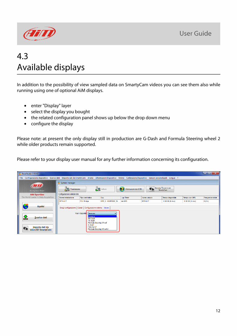
4.3 Available displays
In addition to the possibility of view sampled data on SmartyCam videos you can see them also while running using one of optional AiM displays.
• enter "Display" layer
• select the display you bought
• the related configuration panel shows up below the drop down menu
• configure the display
Please note: at present the only display still in production are G-Dash and Formula Steering wheel 2 while older products remain supported.
Please refer to your display user manual for any further information concerning its configuration.
13
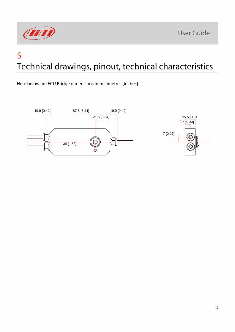
5 Technical drawings, pinout, technical characteristics
Here below are ECU Bridge dimensions in millimetres [inches].
14
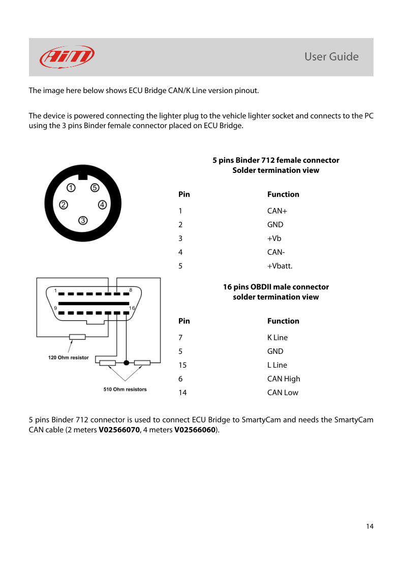
The image here below shows ECU Bridge CAN/K Line version pinout.
The device is powered connecting the lighter plug to the vehicle lighter socket and connects to the PC using the 3 pins Binder female connector placed on ECU Bridge.
5 pins Binder 712 female connector Solder termination view
Pin Function
1 CAN+
2 GND
3 +Vb
4 CAN-
5 +Vbatt.
16 pins OBDII male connector solder termination view
Pin Function
7 K Line
5 GND
15 L Line
6 CAN High
14 CAN Low
5 pins Binder 712 connector is used to connect ECU Bridge to SmartyCam and needs the SmartyCam CAN cable (2 meters V02566070, 4 meters V02566060).
15
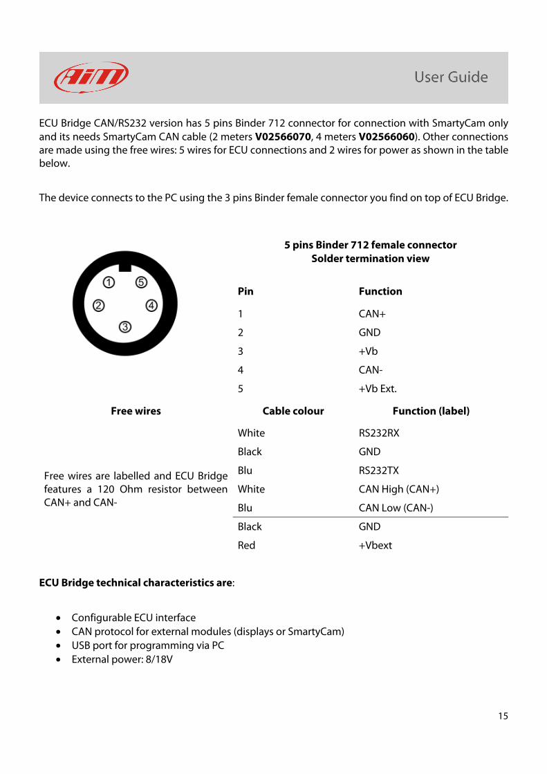
ECU Bridge CAN/RS232 version has 5 pins Binder 712 connector for connection with SmartyCam only and its needs SmartyCam CAN cable (2 meters V02566070, 4 meters V02566060). Other connections are made using the free wires: 5 wires for ECU connections and 2 wires for power as shown in the table below.
The device connects to the PC using the 3 pins Binder female connector you find on top of ECU Bridge.
5 pins Binder 712 female connector Solder termination view
Pin Function
1 CAN+
2 GND
3 +Vb
4 CAN-
5 +Vb Ext.
Free wires Cable colour Function (label)
Free wires are labelled and ECU Bridge features a 120 Ohm resistor between CAN+ and CAN-
White RS232RX
Black GND
Blu RS232TX
White CAN High (CAN+)
Blu CAN Low (CAN-)
Black GND
Red +Vbext
ECU Bridge technical characteristics are:
• Configurable ECU interface
• CAN protocol for external modules (displays or SmartyCam)
• USB port for programming via PC
• External power: 8/18V