Embed Size (px)
Citation preview
8/7/2019 AIAA SideStep
http://slidepdf.com/reader/full/aiaa-sidestep 1/8
Control of a Lateral Helicopter Side-step Maneuver on an
Anthropomorphic Robot
K. Beykirch1, F. M. Nieuwenhuizen2, H. J. Teufel3, H.-G. Nusseck 4, J. S. Butler5, and H. H. Bülthoff 6
Max Planck Institute for Biological Cybernetics, Tübingen, Germany
Our society relies more and more on flight simulation for pilot training to enhance safety
and reduce costs. But to meet the highest level of general technical requirements for
simulators set forth by the FAA and EASA requires high-cost equipment. To make
simulator use more accessible, reduced costs might be achieved with novel simulator designs
and/or through research to improve the performance of existing designs. This report
explores the use of such a novel design, based on an anthropomorphic robot arm to
reproduce an experiment designed to evaluate flight simulator motion requirement for
helicopter pilot training. Results compare promisingly well to those from a large, high-
performance facility where the original work was performed.
I. Introduction
odern flight training relies increasingly on simulator technology to reduce costs and enhance safety 1,2, since
simulators provide a flexible, efficient and safe environment at a much lower cost than real flight3. Pilots
conduct a major part of their training, maintain their flying skills and even renew their licences through simulator
tests4.
M
Confidence in a simulator as a valid tool for research and training depends upon the ability of the simulator to
provide adequate motion cues to the pilot, i.e., its ability to induce adequate human performance for a given task and
environment5,6. Because of the limited kinematic envelope for all motion systems, other than actual aircraft, motion
drive algorithms are required to provide the best use of the available motion envelope 7. This optimization depends
on an accurate set of motion fidelity criteria for the required task, but there is controversy surrounding this issue8,9,10.
To develop motion platform requirements and fidelity criteria for flight simulation of several helicopter
maneuvers, Schroeder12 performed a series of experiments on the Vertical Motion Simulator at NASA AmesResearch Center. He measured both objective performance responses and subjective evaluation the simulator, self-
performance, and perceived motion fidelity. He uses the results, along with results from previous research to
propose fidelity criteria for helicopter flight simulation.
In a companion paper, development of a novel motion simulator, the MPI Motion Simulator, based on an
anthropomorphic robotic arm, is presented11. Due to the larger motion envelope and superior ability to combine
rotation with translation, when compared with similarly priced conventional Stewert platforms, an initial test of the
suitability of the new setup for simulator research was performed.
1 Research Scientist, Max Planck Institute for Biological Cybernetics, P.O. Box 2169, 72012 Tübingen, Germany;
Ph.D. student, Max Planck Institute for Biological Cybernetics, P.O. Box 2169, 72012 Tübingen, Germany;
[email protected]. Student member AIAA.3 Research Assistant, Max Planck Institute for Biological Cybernetics, P.O. Box 2169, 72012 Tübingen, Germany;
VR-System Administrator, [email protected] Research Scientist, Max Planck Institute for Biological Cybernetics, P.O. Box 2169, 72012 Tübingen, Germany;
[email protected] Professor, Max Planck Institute for Biological Cybernetics, P.O. Box 2169, 72012 Tübingen, Germany;
[email protected]. Member AIAA.
American Institute of Aeronautics and Astronautics
1
AIAA Modeling and Simulation Technologies Conference and Exhibit20 - 23 August 2007, Hilton Head, South Carolina
AIAA 2007-680
Copyright © 2007 by Max Planck Institute for Biological Cybernetics. Published by the American Institute of Aeronautics and Astronautics, Inc., with permission.
8/7/2019 AIAA SideStep
http://slidepdf.com/reader/full/aiaa-sidestep 2/8
II. Experiment
A. Task and participants
Participants performed constant-altitude side-steps between two targets presented along an arc centered at the
simulator base. Both left and right side-steps were performed. At the beginning of each trial, participants were
required to hover until they had acquired a steady position at the starting point. When a button on the center stick was pressed, the target moved a constant distance either to the left or right. Participants had to perform a side-step
towards the new target position attempting to optimize control, accuracy with respect to the target, and hover
performance at the final target. After arriving at the final position, subjects needed to hover in front of the target
stably for approximately 5 seconds before they pushed the button on the center stick again, which brought the
simulator back to the starting position. After each such trial, participants gave a rating on their own performance, the
simulator motion fidelity, and on the Cooper-Harper Handling Qualities Ratings scale. In total, seven participants
completed the experiment. Two additional subjects didn’t complete the experiment due to motion sickness. All are
members of the Max Planck Institute for Biological Cybernetics.
B. Apparatus
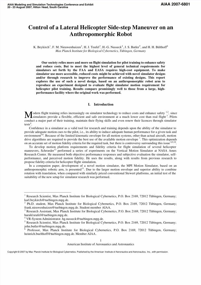
The experiment was performed on the MPI Motion Simulator11 that is based on the Kuka Robocoaster (Kuka
Roboter GmbH, Germany), see Figure 1. The Robocoaster is a 3-2-1 serial robot with a large motion envelope. Thesimulator has the capability to move with all six degrees of freedom, but for this experiment the participants are
translated along an arc using the axis of rotation from the simulator base and are supplied with cues on rolling
motion. As in Schroeder12
, the center of rotation for the role motion was located near the abdomen of the
participants.
Figure 1. The MPI Motion Simulator.
The dynamics of the simulated helicopter are inspired by the dynamics from Schroeder12 and have two degrees of
freedom. Altitude of the center of rolling motion remained constant at 2.66 m, which is also the height of the
participants above the ground in the real world; pitch and yaw with respect to the arc remained zero. The equations
of motion are given as:
,810 lat rollK δ φ φ ⋅⋅+⋅−= &&& Eq. 1
,sin205.12 ⎟⎟ ⎠
⎞⎜⎜⎝
⎛ ⋅⋅+⋅−=
roll
lat K
K φ
θ θ &&& Eq. 2
American Institute of Aeronautics and Astronautics
2
8/7/2019 AIAA SideStep
http://slidepdf.com/reader/full/aiaa-sidestep 3/8
where φ is the roll angle, lat δ is the displacement of the center stick (normalized from -1 to 1), and θ is the
rotation of the simulator base. The original coefficients were slightly modified from Schroeder12
based on feedback
from two experienced helicopter pilots at the institute. Their impression of what felt closest to a real helicopter was
used to tune the parameters.
The motion gains K roll and K lat are also given in Equations 1 and 2, and only scale the motion cues from the
system dynamics. As there is no frequency dependency of the motion filters, the motion of the simulator is in phase
with the visual presentation. The gains of the motion channels are varied systematically according to the samescheme used by Schroeder12 with one additional combination (K roll and K lat both equal to 0.2), as shown in Table 1.
The visual cues were presented through a Head Mounted Display (HMD) (eMagin, USA) with a diagonal field of
view of 40°. Participants controlled the helicopter dynamics with a center stick that is custom combination of a G-
Stick (Flight-Link, USA) and a FlyBox (BG Systems, USA).
Table 1: Experimental motion conditions.
Condition Klat Kroll
1 0.0 0.0
2 0.2 0.2
3 0.4 0.2
4 0.4 0.4
5 0.4 0.6
6 0.6 0.27 0.6 0.4
8 0.6 0.6
9 0.8 0.2
10 0.8 0.4
11 0.8 0.6
12 1.0 1.0
C. Experimental procedure
The experiment was carried out with non-pilots. In order to be able to use subjective ratings, participants needed
to have a frame of reference and a baseline condition upon which to make their judgments. Therefore, participants
were trained on the simulator, but without distortion of motion cues and without the HMD. They were instructed toconsider this “real world” experience as the baseline for all judgments. Generally, participants quickly learned to
control the dynamics and perform the hovering and side-step task with sufficient performance.
The experiment consisted of 4 blocks. Before the experiment, participants had to hover and make side-step
maneuvers in the real world for a minimum of 10 minutes, but were allowed to take as long as they felt was
necessary to be familiar with “the real helicopter”. Each block lasted approximately 15 minutes and contained all
motion conditions, which were presented randomly. Participants had to perform a balance of both left- and
rightward side-step maneuvers. After each trial, the participants gave their subjective ratings. They had to report on
their own performance with a rating of 1 (good), 2 (adequate), or 3 (inadequate). The motion fidelity was rated
either 1 (comparable to real world), 2 (different from the real world, but not distracting), and 3 (different from the
real world and distracting). Finally, participants were asked to give a rating on the Cooper-Harper Handling
Qualities Rating Scale, as modified by Schroeder12
. This scale consists of values from 10 (uncontrollable) to 1
(highly desirable and excellent aircraft characteristics). After each block, participants could rest and, before
beginning the next experimental block, were required to perform the “real world” hover and side-step maneuvers for
at least 5 minutes.
D. Independent variables and dependent measures
The independent variables in this experiment are the motion gains for the roll and lateral motion. These are
varied systematically to uncover their effect on subjective ratings and objective measures.
Subjective ratings are given in three categories: a rating of performance, a rating of the motion fidelity with
respect to the motion experienced before starting the measurements, and a rating based on the Cooper-Harper
Handling Qualities Rating Scale. The objective measures are based on the control behavior of the participants and
American Institute of Aeronautics and Astronautics
3
8/7/2019 AIAA SideStep
http://slidepdf.com/reader/full/aiaa-sidestep 4/8
include positioning performance and control activity. These measures are calculated from control and position
signals that are measured and recorded during each experimental trial.
III. Results and discussion
The results are divided into two categories: objective measurements, which include signals measured during the
experiment, and subjective ratings, which were given by the participants after each experimental trial.
-0.5 0 0.5 1 1.5 2 2.5 3 3.5 4-1
-0.5
0
0.5
1
1.5
2
2.5
Lateral position, m
L a t e r a
l v e l o c i t y , m / s
No motion
Full motion
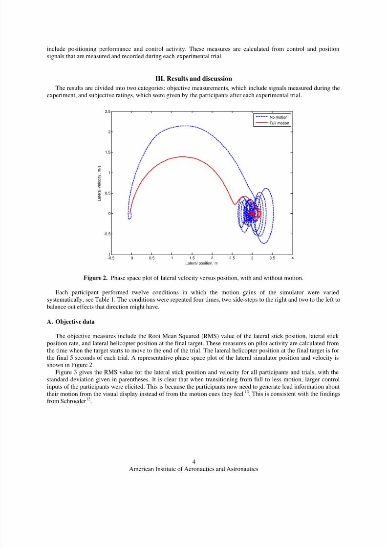
Figure 2. Phase space plot of lateral velocity versus position, with and without motion.
Each participant performed twelve conditions in which the motion gains of the simulator were varied
systematically, see Table 1. The conditions were repeated four times, two side-steps to the right and two to the left to
balance out effects that direction might have.
A. Objective data
The objective measures include the Root Mean Squared (RMS) value of the lateral stick position, lateral stick
position rate, and lateral helicopter position at the final target. These measures on pilot activity are calculated from
the time when the target starts to move to the end of the trial. The lateral helicopter position at the final target is for
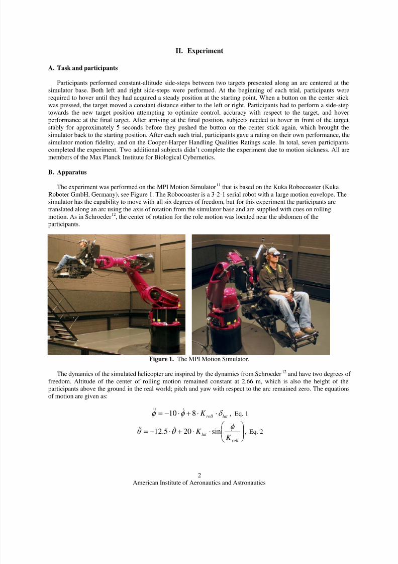
the final 5 seconds of each trial. A representative phase space plot of the lateral simulator position and velocity is
shown in Figure 2.
Figure 3 gives the RMS value for the lateral stick position and velocity for all participants and trials, with the
standard deviation given in parentheses. It is clear that when transitioning from full to less motion, larger control
inputs of the participants were elicited. This is because the participants now need to generate lead information about
their motion from the visual display instead of from the motion cues they feel13. This is consistent with the findings
from Schroeder12.
American Institute of Aeronautics and Astronautics
4
8/7/2019 AIAA SideStep
http://slidepdf.com/reader/full/aiaa-sidestep 5/8
Klat
K r o l l
16.52
(8.10)
20.94
(7.36)
27.01
(10.98)
28.99
(12.37)
24.37
(9.20)
22.79
(9.06)
26.78
(10.64)
23.57
(9.86)
20.15
(8.84)
27.36
(9.09)
24.48
(7.89)
22.71
(8.10)
3 - Average
(3) - Std. dev.
0 0.2 0.4 0.6 0.8 10
0.2
0.4
0.6
0.8
1
18
19
20
21
22
23
24
25
26
27
28
K
lat
K r o l l
1.83
(0.57)
2.18
(0.59)
2.25
(0.59)
2.33
(0.60)
2.15
(0.42)
2.23
(0.47)
2.28
(0.59)
2.14
(0.49)
2.03
(0.57)
2.25
(0.49)
2.15
(0.40)
2.18
(0.55)
3 - Average
(3) - Std. dev.
0 0.2 0.4 0.6 0.8 10
0.2
0.4
0.6
0.8
1
1.9
1.95
2
2.05
2.1
2.15
2.2
2.25
2.3
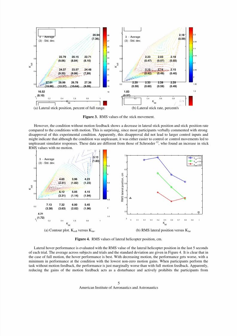
(a) Lateral stick position, percent of full range. (b) Lateral stick rate, percent/s
Figure 3. RMS values of the stick movement.
However, the condition without motion feedback shows a decrease in lateral stick position and stick position rate
compared to the conditions with motion. This is surprising, since most participants verbally commented with strong
disapproval of this experimental condition. Apparently, this disapproval did not lead to larger control inputs and
might indicate that although the condition was unpleasant, it was either easier to control or control movements led to
unpleasant simulator responses. These data are different from those of Schroeder12, who found an increase in stick
RMS values with no motion.
Klat
K r o l l
4.21
(1.72)
3.13
(1.83)
7.13
(3.38)
7.32
(3.63)
6.12
(3.31)
4.65
(2.51)
6.00
(2.02)
5.05
(1.14)
3.96
(1.82)
5.45
(1.96)
4.15
(1.94)
4.23
(1.23)
3 - Average
(3) - Std. dev.
0 0.2 0.4 0.6 0.8 10
0.2
0.4
0.6
0.8
1
3.5
4
4.5
5
5.5
6
6.5
7
0 0.1 0.2 0.3 0.4 0.5 0.6 0.7 0.8 0.9 13
3.5
4
4.5
5
5.5
6
6.5
7
7.5
Klat
R M S
l a t e r a l p o s i t i o n , c m
Kroll
= 0.2
Kroll
= 0.4
Kroll
= 0.6
(a) Contour plot. Kroll versus Klat. (b) RMS lateral position versus Klat
Figure 4. RMS values of lateral helicopter position, cm.
Lateral hover performance is evaluated with the RMS value of the lateral helicopter position in the last 5 seconds
of each trial. The average across subjects and trials and the standard deviation are given in Figure 4. It is clear that in
the case of full motion, the hover performance is best. With decreasing motion, the performance gets worse, with a
minimum in performance at the condition with the lowest non-zero motion gains. When participants perform the
task without motion feedback, the performance is just marginally worse than with full motion feedback. Apparently,
reducing the gains of the motion feedback acts as a disturbance and actively prohibits the participants from
American Institute of Aeronautics and Astronautics
5

8/7/2019 AIAA SideStep
http://slidepdf.com/reader/full/aiaa-sidestep 6/8
performing the task well. When the source of conflict with the visual feedback is taken away, the task can be
performed better again.
B. Subjective data
The pilot performance ratings indicate how well a trial was performed according to the participants. The scale
consisted of three numerical levels: 1 (good), 2(adequate), and 3 (inadequate). Figure 5 gives the results averaged
across all participants and trials.
The performance rating shows the same trend as the RMS of the stick position. Participants rate their
performance in conditions with full motion cues the best. Performance in the condition without motion is rated
better than the conditions with low motion gains.
When looking at an increase in lateral motion gain with respect to the roll motion gain, the ratings on pilot
performance indicate that an increase in roll motion gain is better than increasing the lateral motion gain. This is
especially true in the region with low motion gains.
Klat
K r o l l
1.54
(0.51)
1.25
(0.32)
2.07
(0.45)
1.96
(0.53)
1.64
(0.66)
1.61
(0.67)
2.00
(0.35)
1.43
(0.37)
1.39
(0.45)
1.86
(0.43)
1.39
(0.35)
1.50
(0.29)
3 - Average
(3) - Std. dev.
0 0.2 0.4 0.6 0.8 10
0.2
0.4
0.6
0.8
1
1.3
1.4
1.5
1.6
1.7
1.8
1.9
2
0 0.1 0.2 0.3 0.4 0.5 0.6 0.7 0.8 0.9 1
1.3
1.4
1.5
1.6
1.7
1.8
1.9
2
2.1
Klat
P i l o t r a t i n g
Kroll
= 0.2
Kroll
= 0.4
Kroll
= 0.6
(a) Contour plot. Kroll versus Klat. (b) Pilot’s self-rating versus Klat
Figure 5. Participant rating on performance.
The motion fidelity ratings also consisted of three numerical levels: 1 (comparable to real world), 2 (different
from the real world, but not distracting), and 3 (different from the real world and distracting). Participants were
instructed to compare the motion fidelity with the motion behavior in the hover task in the “real world” without any
motion distortion.
American Institute of Aeronautics and Astronautics
6
8/7/2019 AIAA SideStep
http://slidepdf.com/reader/full/aiaa-sidestep 7/8
Klat
K r o l l
2.86
(0.38)
1.46
(0.44)
2.79
(0.30)
2.54
(0.34)
2.21
(0.51)
2.11
(0.50)
2.21
(0.37)
1.89
(0.38)
1.82
(0.45)
1.96
(0.49)
1.64
(0.38)
1.43
(0.31)
3 - Average
(3) - Std. dev.
0 0.2 0.4 0.6 0.8 10
0.2
0.4
0.6
0.8
1
1.6
1.8
2
2.2
2.4
2.6
0 0.1 0.2 0.3 0.4 0.5 0.6 0.7 0.8 0.9 1
1.3
1.4
1.5
1.6
1.7
1.8
1.9
2
2.1
Klat
P i l o t r a t i n g
Kroll
= 0.2
Kroll
= 0.4
Kroll
= 0.6
(a) Contour plot. Kroll versus Klat. (b) Motion fidelity ratings versus Klat
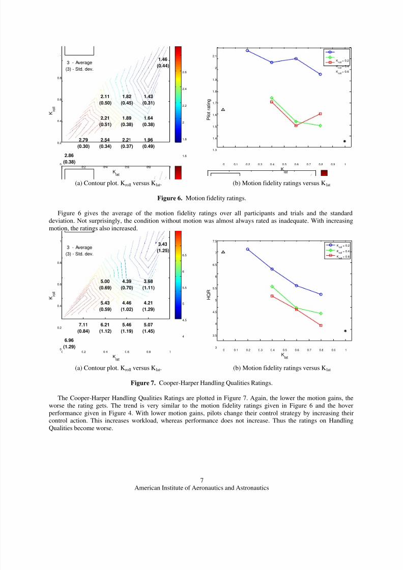
Figure 6. Motion fidelity ratings.
Figure 6 gives the average of the motion fidelity ratings over all participants and trials and the standard
deviation. Not surprisingly, the condition without motion was almost always rated as inadequate. With increasing
motion, the ratings also increased.
Klat
K r o l l
6.96
(1.29)
3.43
(1.25)
7.11
(0.84)
6.21
(1.12)
5.43
(0.59)
5.00
(0.69)
5.46
(1.19)
4.46
(1.02)
4.39
(0.70)
5.07
(1.45)
4.21
(1.29)
3.68
(1.11)
3 - Average
(3) - Std. dev.
0 0.2 0.4 0.6 0.8 10
0.2
0.4
0.6
0.8
1
4
4.5
5
5.5
6
6.5
0 0.1 0.2 0.3 0.4 0.5 0.6 0.7 0.8 0.9 13
3.5
4
4.5
5
5.5
6
6.5
7
7.5
Klat
H
Q R
Kroll
= 0.2
Kroll
= 0.4
Kroll
= 0.6
(a) Contour plot. Kroll versus Klat. (b) Motion fidelity ratings versus Klat
Figure 7. Cooper-Harper Handling Qualities Ratings.
The Cooper-Harper Handling Qualities Ratings are plotted in Figure 7. Again, the lower the motion gains, theworse the rating gets. The trend is very similar to the motion fidelity ratings given in Figure 6 and the hover
performance given in Figure 4. With lower motion gains, pilots change their control strategy by increasing their
control action. This increases workload, whereas performance does not increase. Thus the ratings on Handling
Qualities become worse.
American Institute of Aeronautics and Astronautics
7

8/7/2019 AIAA SideStep
http://slidepdf.com/reader/full/aiaa-sidestep 8/8
IV. Conclusion
Although there were several important differences between this experiment and that of Schroeder 12, the main
results were reproduced. These experimental differences include the use of non-pilots, a small field-of-view HMD,
and lateral motion on an arc, rather than a straight line. It is unclear why the performance of the subjects was quite
good with no motion, but it may relate to the lack of experience in comparison to the professional pilots used by
Schroeder12.
The results also demonstrate the application of the new MPI Motion Simulator for helicopter flight simulationresearch. With planned improvements to expand the motion envelope and improve visualization11, continued
research, including the use of trained pilots, is planned
References1Hettinger, L.J., Haas, M.W., Virtual and Adaptive Environments – Applications, Implications and Human Performance
Issues. Mahwah (NJ), Lawrence Erlbaum, 20042Anon., “Seeking the Proper Balance Between Simulation and Flight Test,” AIAA position paper by the AIAA Flight Test
Technical Committee, October 1999.3Ray, P.A., “Quality Flight Simulation: Why?” Proceedings of the AIAA Flight Simulation Technologies Conference, San
Diego(CA), AIAA 1996-3488, July 29-31, 1996 pp. 138-147.4Burki-Cohen, J., Go, T.H., Longridge, T., “Flight Simulator Fidelity Considerations for Total Air Line Pilot Training and
Evaluation,” Proceedings of the AIAA Modelling and Simulation Technologies Conference, Montreal, Canada , AIAA 2001-
4425, August 6-9, 2001
5Durlach, N., Allen, G., Darken, R., Garnett, R.L., Loomis, J.M., Templeman, J., Von Wiegand, T.E., “Virtual Environmentsand the Enhancement of Spatial Behavior: Towards a Comprehensive Research Agenda,” PRESENCE: Tele-operators and
Virtual Environments, 9(6), 2000, pp. 593-6156Hess, R.A., Malsbury, T. “Closed-Loop Assessment of Flight Simulator Fidelity” Journal of Guidance, Control and
Dynamics, 14(1), 1991, pp. 191-1977Conrad, B., Schmidt, S.F., Douvillier, J.G. “Washout circuit design for multi-degrees of freedom moving base simulators,”
Proceedings of the AIAA Visual and Motion Simulation Conference, Palo Alto (CA ), AIAA-1973-929, September 10-12, 1973
8Burki-Cohen, J., Go, T.H., Chung, W.Y., Schroeder, J., Jacobs, S., Longridge, T., “Simulator Fidelity Requirements forAirline Pilot Training and Evaluation Continued: An Update on Motion Requirements Research,” Proceedings of the 12th
International Symposium on Aviation Psychology , Dayton (OH), April 14-17, 2003, pp. 182-1899Cardullo, F. M.: An Assessment of the Importance of Motion Cuing Based on the Relationship Between Simulated Aircraft
Dynamics and Pilot Performance: A Review of the Literature. Paper No. 91-2980, Proceedings of the AIAA Flight SimulationTechnologies Conference, New Orleans, La., 1991, pp. 436-447.
10Hall, J. R., “The Need for Platform Motion in Modern Piloted Flight Training Simulators,” Technical Memorandum FM35,The Royal Aerospace Establishment, Bedford, U. K., Oct. 1989.
11Teufel, H. J., Nusseck, H.-G., Beykirch, K., Butler, J. S., Kerger, M., and Bülthoff, H. H., “MPI Motion Simulator:Development and Analysis of a Novel Motion Simulator,” Proceedings of the AIAA Modeling and Simulation Technologies
Conference and Exhibit, Hilton Head (SC), No. AIAA-2007-6476, 20-23 Aug. 2007.12Schroeder, J. A., “Helicopter Flight Simulation Motion Platform Requirements,” Tech. Rep. NASA/TP-1999-208766,
NASA, July 1999.13Nieuwenhuizen, F. M., Beykirch, K., Mulder, M., and Bülthoff, H. H., “Identification of Pilot Control Behavior in a Roll-
Lateral Helicopter Hover Task,” Proceedings of the AIAA Modeling and Simulation Technologies Conference and Exhibit, Hilton
Head (SC), No. AIAA-2007-6476, 20-23 Aug. 2007.
American Institute of Aeronautics and Astronautics
8


![, Allen, C., & Rendall, T. (2019). Efficient Aero-Structural Wing AIAA Scitech … · In AIAA Scitech 2019 Forum [AIAA 2019-1701] (AIAA Scitech 2019 Forum). American Institute of](https://img.pdfslide.us/doc/110x75/6089b44b26d0b4646a6cbe59/-allen-c-rendall-t-2019-efficient-aero-structural-wing-aiaa-scitech.jpg)