Embed Size (px)
Citation preview

46th Aerospace Sciences Meeting, January 7-10, 2008, Reno, Nevada
A Smart Wind Turbine Blade Using Distributed
Plasma Actuators for Improved Performance
Robert C. Nelson∗ Thomas C. Corke†and Hesham Othman‡
University of Notre Dame, Notre Dame, IN 46556
Mehul P. Patel§ Srikanth Vasudevan¶and Terry Ng‖
Orbital Research Inc., Cleveland, OH 44103
This paper presents an innovative Plasma Aerodynamic Control Effectors (PACE) con-cept for improved performance of wind turbines. The concept is aimed towards the designof “smart” wind turbine blades with integrated sensor-actuator-controller modules to im-prove the performance of wind turbines. The system will be designed to enhance energycapture, and reduce aerodynamic loading and noise by way of virtual aerodynamic shaping.Virtual shaping is the modification of the flow field around the surface by means of flowcontrol (plasma actuators), which results in flow changes as if the geometry itself is altered.In effect the flow control scheme is giving the designer the capability to change the effectivepitch distribution across the turbine blade as needed to control blade loading. The presentconcept is based on the use of surface-mountable, single dielectric barrier discharge (SDBD)plasma actuators on the turbine blades for increased energy capture and noise reduction.The system will allow continuous operation of wind turbines at near optimal conditions(as close as possible to the rated power coefficient) using a smart/adaptive PACE systemin both steady and unsteady conditions (wind gusts, varying wind speeds, etc.), therebyensuring safety and optimal power capture for electricity conversion. Experimental dataand computational model results are presented that show the feasibility of using plasmaflow actuators to control the aerodynamic characteristics of selected wind turbine airfoilsections. Two airfoil profiles designed for wind turbine applications were selected for thisstudy. These were the S827 and the S822 profiles. The S827 airfoil was used to examinecirculation control to increase the effective camber, and leading-edge separation control toincrease Clmax
. The S822 airfoil was used to demonstrate geometric changes that promotelocal flow separations that can be manipulated by plasma actuators to control lift. Boththese approaches produced controlled changes in the lift coefficients on the airfoils thatwere equivalent to a trailing-edge flap or a leading-edge slat, but without conventionalmoving surfaces.
∗Professor, Department of Aerospace & Mechanical Engineering, 106 Hessert Laboratory for Aerospace Research, Universityof Notre Dame, Notre Dame, IN 46556, AIAA Fellow.
†Clark Chair Professor, Department of Aerospace & Mechanical Engineering, 101 Hessert Laboratory for Aerospace Research,University of Notre Dame, Notre Dame, IN 46556, Associate Fellow AIAA.
‡Post-doctoral Research Associate, Department of Aerospace & Mechanical Engineering, Hessert Laboratory for AerospaceResearch, University of Notre Dame, Notre Dame, IN 46556
§Director, Aerodynamics Group, Orbital Research, Inc., 4415 Euclid Ave., Suite 500, Cleveland, OH 44103,Senior Member,AIAA.
¶Aerospace Engineer, Aerodynamics Group, Orbital Research, Inc., 4415 Euclid Ave., Suite 500, Cleveland, OH 44103,Member AIAA
‖Chief Aerodynamicist, Aerodynamics Group, Orbital Research, Inc., 4415 Euclid Ave., Suite 500, Cleveland, OH 44103,Senior Member AIAA
1 of 17
American Institute of Aeronautics and Astronautics Paper 2008-1312

Nomenclature
Symbol Meaning
C airfoil chord length
Cd drag coefficient
Cf flap chord length
Cl lift coefficient
Clmaxmaximum lift coefficient
Cr trailing-edge ramp chord length
Lsep length of separation region
Tcontrol time period for unsteady operation = 1/f
Tsignal actuator on time period for unsteady operation
Rec Reynolds number based on axial chord length and free-stream velocity
U∞ free-stream velocity
f excitation frequency of unsteady DBD actuator= 1/Tcontrol
q dynamic pressure
x, y, z axial coordinates
α angle of attack
αs stall angle of attack
ρ density of air
I. Introduction
The recognition of the value of wind energy as a low cost, clean source for electricity is creating new busi-ness opportunities for manufacturing and materials innovation. Worldwide growth in wind power generationsince 1994 has been 30% or higher annually.1 However, the wind power industry must still make substantialreductions in the cost per kilowatt hour to become competitive with fossil powered generating technologies.This can only come by improving wind turbine efficiency over a wider range of wind conditions and loweringconstruction costs. The cost of producing electricity from wind power is a function of the acquisition cost ofthe wind turbine system, lease or land purchase for the wind farm, transmission requirements to connect tothe power grid, maintenance, and the amount of time the wind conditions are within the operational rangeof the wind turbine system. Each new generation wind turbine design has exploited improved technologiesin blade aerodynamics, materials, controls, and generator innovations to lower system cost and expand theoperational hours of the turbine per year.
These technologies all help in lowering the systems life cycle costs. In the 1970s most horizontal axis windturbines (HAWTs) used airfoils designed by the National Advisory Committee for Aeronautics (NACA) thatwere designed for the aviation industry. NACA airfoils were designed for airplanes that operate in a Reynoldsnumber range much higher than that experienced by wind turbine blades. When such airfoils are used atlower Reynolds numbers the airfoils suffered severe performance degradation from leading edge roughnesscontamination due to insect impact, or airborne pollutants. Tangler and Somers2 discuss the evolution ofairfoils used by the wind power industry. The aerodynamic performance loss using the NACA airfoil sectionsresulted in significant annual energy losses for wind turbines using these airfoils in their blade design. Inthe mid 1980s the National Renewable Energy Laboratory (NREL) as well as European research centerssponsored the development of a new family of airfoil sections designed to meet the needs of stall, variablepitch and variable rpm regulated wind turbines. Tangler and Somers2 estimated that using the NREL airfoilswould achieve annual energy improvements for stall, variable pitch, and variable rpm regulated wind turbinesof (23-35%), (8-20%), and (8-10%), respectively.
The control of blade loading on large wind turbines also changed markedly in the last twenty years.Until the 1990s most wind turbines were designed to control blade loading and power output using a passivecontrol strategy of controlling the power output and rotor speed by stall regulation. In a stall regulatedturbine as the wind speed increases the blades begin to stall. The increased drag makes the turbine lessefficient thereby regulating the power extraction of the turbine. The large wind turbines designed in the1990s use active control to regulate rotor speed and power output by controlling the blade pitch angle of the
2 of 17
American Institute of Aeronautics and Astronautics Paper 2008-1312

turbine blades. Having the ability to control the blade pitch allowed for more efficient operation and bladeload control. In addition the use of active load control permitted designers the option to use lighter weightturbine blades.
The challenging issues facing the wind turbine designer include; regulation of the power output in highwinds, providing a steady power output with time, and alleviation of large transient blade loadings. Webelieve that plasma flow control technology3 offers the potential of improving wind turbine performanceby expanding the operating wind range, controlling unsteady blade loadings, increasing blade fatigue lifeand reducing the noise of the wind turbine system. These benefits can be used to expand the operationaltime the wind turbine can be generating electricity. Increasing operational time allows more revenue to begenerated by the turbine system and makes the machine more cost competitive with other electric generatingtechnologies.
The most promising technology for making additional improvements in the control of blade aerodynamicloading is by applying active flow control technology in a distributed manner across each blade. A systemincorporating active flow control technology is one that includes flow actuators, flow sensors and control logicto use the sensor information on the state of the flow (separated or attached) and section loading to driveflow actuators to achieve a desired performance benefit. While there are a variety of flow control devicesthat could be used on a wind turbine; for example micro tabs, suction, blowing, synthetic jets and variablecambered airfoils using shaped memory materials, we believe that the dielectric barrier discharge (DBD)plasma actuator offers the greatest promise for wind turbine flow control.
Plasma enhanced aerodynamics using single-dielectric barrier discharge (SDBD) “plasma actuators” hasbeen demonstrated in a range of applications involving separation control, lift enhancement, drag reductionand flight control without moving surfaces.4–15 These actuators consists of thin electrodes separated by adielectric insulator. One of the electrodes is typically exposed to the air. The other electrode is fully coveredby a dielectric material. A schematic illustration is shown in Figure 1. A high voltage ac potential is suppliedto the electrodes. When the ac amplitude is large enough, the air ionizes in the region of the largest electricpotential. This generally begins at the edge of the electrode that is exposed to the air, and spreads out overthe area projected by the covered electrode. The ionized air (plasma) in the presence of the electric fieldproduced by the electrodes results in a body force on the ambient air. Details of the physics and mechanismof the plasma actuator are provided by Enloe et al.16, 17 Corke et al.3 provide a recent general review ofSDBD plasma actuators.
Figure 1. Schematic drawing of asymmetric electrode arrangement for plasma actuators.
DBD plasma actuators have a number of distinct advantages over other active flow control devices. Someof the advantages of using DBD plasma actuators for flow control on a wind turbine blade include thefollowing:
• The actuators are fully electronic with no moving parts,
• They can withstand high force loadings,
• They can be laminated into the turbine blade surface,
• No slots or cavities are required,
• Actuators can be operated in both steady and unsteady modes,
• Actuators have high bandwidth so they have fast response for feedback control,
3 of 17
American Institute of Aeronautics and Astronautics Paper 2008-1312

• They have low power consumption (2-4 Watts per foot for unsteady operation)
The body force vector can be tailored through the design of the electrode arrangement. Turbulentseparation control can be achieved either by the injection of high momentum fluid, or by circulating highmomentum fluid in the free-stream or outer part of the boundary layer towards the wall. The spanwiseelectrode arrangement which is often used in laminar separation control, provides the former approach. Thebody force generated by this arrangement accelerates fluid towards the separation location to overcomethe adverse pressure gradient. To enhance boundary layer mixing, a streamwise electrode arrangement wasdesigned in order to generate a pair of counter-rotating vortices that are intended to circulate high momentumfluid from outer part of the boundary layer towards the wall to delay or suppress flow separation.
In addition to the experimental use of the plasma actuators, models for the space-time evolution ofthe plasma generation over the actuator, and a first-principle formulation for the body force produced bythe plasma on the ambient flow, have been implemented in numerical flow solvers.18–20 These have pro-duced excellent agreement with experiments on leading-edge separation control in both steady and unsteadycases. Their purpose is to provide simulations that can be used in optimizing the design and placement ofplasma actuators for different applications of flow control, for example like wind turbine blades, to enhanceaerodynamic performance.
The further improvement in wind turbine aerodynamics and control will require active control technologyto create a “smart” turbine blade. The most commonly used devices for controlling aerodynamic loading areleading edge flaps or slats and trailing edge flaps. Figure 2 shows the aerodynamic changes created by eachmechanical device. The leading edge flap or slat extends the lift curve thereby increasing the maximum liftcoefficient, Clmax
, and stall angle. A trailing edge flap changes the effective camber of the airfoil and shiftsthe zero-lift angle of attack to negative or positive values depending on the direction of the flap (positive ornegative) deflection. The trailing edge flap is well suited for controlling the lift on any lifting surface and canbe thought of as a “direct lift controller”. Trailing edge flaps have also been examined for wind turbine controlapplications.21, 22 While these studies showed that trailing edge flaps were effective in controlling the poweroutput and providing blade load mitigation, the major disadvantage of mechanical flaps is their complexity,added structural weight (linkages, support structure, actuators, etc.) and additional maintenance. Thedisadvantages of mechanical flaps could be avoided if flow control devices without moving surfaces, like theplasma actuators, were used. In the following section we will highlight the potential benefits of active flowcontrol technology in the form of plasma flow actuators for wind turbine applications.
Figure 2. The aerodynamic changes created by leading and trailing edge flow enhancement devices.
4 of 17
American Institute of Aeronautics and Astronautics Paper 2008-1312

A. Smart Turbine Blade Concept
New wind turbine designs include the capability of changing the blade pitch to improve energy extraction. Ina steady wind condition, the power extracted can be achieved by optimizing the blade pitch angle by rotatingthe blade within the turbine hub. Further improvements in performance can be achieved by controlling eachblade individually. In this control scheme, the entire blade is rotated to obtain the best power extractionfor the given wind conditions. While this is an improvement over a fixed pitch blade, the blade can stillexperience regions of stall and unsteady loading during each rotation. To achieve an optimum performanceimprovement in a velocity field that varies both spatially and temporally across the blade, one would needto be able to adjust the local blade pitch angle across the turbine blade. The distribution of active flowcontrol can be used to optimize the wind power extraction of the system and to moderate the blade loadingacross the span of the blade.
In unsteady wind conditions, the problem is one where the local spanwise pitch needs to be changed.Distributed flow control permits local aerodynamic load control that is equivalent to an effective local pitchangle change. The change in the flow field gives rise to what we call virtual shaping of the airfoil section.Virtual shaping is the modification of the flow field around the surface by means of flow control (plasmaactuators), which results in flow changes as if the geometry itself is altered. By incorporating the distributedflow actuators, sensors with the appropriate control logic one can envision the possibility that multiple controlobjectives could be accomplished. Figure 3 is a sketch showing a simple arrangement of plasma actuatorsdistributed near the leading edge and trailing edge. The basic idea is to divide the blade into regions thatcan be individually controlled. The spacing of actuators and number of sections would be determined by thedesired control function. The virtual trailing edge flap actuators would be located on both upper and lowersurface of the airfoil section.
Figure 3. Example of distributed DBD flow control actuators on wind turbine blade.
A paper by G. van Kuik, T. Barlas, and G. van Bussel23 outlined the need for improved blade controlconcepts for the next generation of large wind turbine designs that are expected to enter service in the year2020. They presented an overview of various control technologies that could be used to design a smart turbineblade. A truly smart turbine blade would use distributed sensors, flow control actuators and a supervisorycontroller to select the appropriate control logic for using the flow actuators. The supervisory controllerwould select different control logic depending on the needed control, i.e., blade loading control, blade stallprevention, or braking torque for emergency shut down. The point here is that distributed control gives thedesigner the potential for optimally controlling a variety of wind turbine control tasks. Table 1 provides asummary of some of the potential benefits afforded by distributed plasma flow actuators.
In the following sections we will presents results of active flow control experiments using SDBD plasma
5 of 17
American Institute of Aeronautics and Astronautics Paper 2008-1312

Table 1. Potential advantages of Distributed Virtual Plasma Slats and Flaps.
Benefits of Active Flow Control Technology Wind Turbine Improvement
Distributed Virtual Plasma Flaps can be used tocontrol large transient loads due to unsteady windconditions.
Controlling transient blade loading lowers bladeroot bending moment transients. This will im-prove turbine blade fatigue life and allows opera-tion over a wider range of wind conditions.
Distributed Virtual Plasma Flaps can be used tocontrol rotor speed.
Emergency shut down requires redundant controlcapability. Virtual slats and flaps could be used tohelp brake the turbine by provide braking torque.This will provide greater control flexibility.
Distributed Virtual Plasma Flaps can allow largerspan turbine blades.
Turbine blades of greater span can be designedif load control is available to attenuate transientblade loading due to unsteady wind conditions.Increasing blade span permits greater energy ex-traction.
Wind turbine spacing is governed by wake flow in-terference between wind turbines in the wind farm.Distributed Virtual Plasma Flaps may allow moreefficient turbine performance from down wind tur-bines
Virtual Plasma Flaps can allow improved energyextraction from down wind turbines by optimiz-ing the aerodynamic loads across the blades. Mayallow more wind turbine to be placed on a giventrack of land than is currently possible.
Distributed Virtual Plasma Slats can controlClmax
that will allow improved performance onstall regulated wind turbines. It may also be use-ful in turbine startup.
Virtual Plasma Slats could be used to controlblade section Clmax
.
actuators on airfoil sections that are typical of wind turbines. These are intended to demonstrate theirpotential for distributed dynamic active lift control.
II. Experimental Setup
The objective of the experimental study was to demonstrate the feasibility of incorporating the PlasmaAerodynamic Control Effectors (PACE) system for improving wind turbine performance and control. Theexperiments were conducted in a subsonic wind tunnel at the Center for Flow Physics and Control at theUniversity of Notre Dame. The wind tunnel used was a low turbulence, in-draft (open-return) design. Thetest section has a square cross-section of 2 ft x 2 ft (0.61m x 0.61m) and a test section length of 6 ft (1.8m).The tunnel is capable of producing velocities in a range of 5 to 35m/sec, with a turbulence level of 0.08%over the velocity range.
The airfoil models were mounted vertically by way of a sting connected to a lift and drag force balancelocated on the top of the test section. End-plates were mounted to the test section ceiling and floor toproduce approximately two dimensional flow over the airfoil. The end-plates were secured to the walls ofthe test section and were separated from the airfoil by a small gap. A schematic of the force balance andtest section is shown in Figure 4.
Two airfoil profiles designed for wind turbine applications were selected for this study. These were theS82724 and the S82225 profiles. The section shape for the S827 airfoil is shown in Figure 5. The sectionshape for the S822 is shown in Figure 6, where the solid curve is the baseline shape and the dashed curveshows the shape as modified to add flow separation ramps at the trailing edge.
III. Experimental Results
Experiments were performed on both airfoil shapes to determine the effect of placing DBD plasmaactuators in different configurations and locations on the lift and drag. The objectives for the two profile
6 of 17
American Institute of Aeronautics and Astronautics Paper 2008-1312

Figure 4. Schematic of experimental setup used for measuring lift and drag at different angles of attack onturbine blade sections.
Figure 5. Section shape of S827 airfoil used in DBD flow control experiments.
Figure 6. Section shapes of baseline S822 airfoil (solid curve) and modified shape (dashed curve) to add flowseparation ramps.
7 of 17
American Institute of Aeronautics and Astronautics Paper 2008-1312
shapes were different. For the S827 section shape, the objective was to use steady plasma actuators thathave been shown to provide circulation control that is equivalent to increasing the effective camber.10, 28, 29
For the S822 section shape, the objective was to modify the profile to produce flow separation ramps thatcould be manipulated by the plasma actuators to produce different pressure distributions near the trailingedge. The advantage of this approach is that it can be accomplished with unsteady plasma actuators thatcan potentially use only 10% of the power of the steady plasma actuators.
The airfoils were cast from molds that were machined using a numerically controlled milling machine.The casting material consisted of a two-part epoxy that was mixed with micro-glass spheres. The resultingairfoils were extremely rigid, with a smooth hard surface. The chord length of the S827 airfoil was 29.9 cm(11.75 in). The chord length of the S822 airfoil was slightly larger at 30 cm (12.2 in).
A. S827 Profile
Both spanwise and streamwise plasma actuator configurations were investigated in this study. The spanwiseplasma actuator configuration was based on the asymmetric configuration that was shown in Figure 1. Theelectrodes were made from 0.0254mm thick copper foil tape. The dielectric material was 6.4mm (0.25 in)thick Teflon sheet. The Teflon was recessed into the airfoil so that the exposed surface was flush withthe surface of the airfoil. The edges of the electrodes were aligned in the spanwise direction. They wereoverlapped by a small amount (of the order of 1 mm), in order to ensure a uniform plasma in the full spanwisedirection. The junction of the exposed electrode and the covered electrode was placed at x/C = 0.78.
The experiments were conducted at a 20m/s free-stream speed. This gave a chord Reynolds number of0.404×106. The actuator ran in steady operation. The frequency of the ac voltage supplied to the electrodeswas approximately 2.3 kHz. The precise frequency was tuned to maximize the body force and minimize ohmicheating.20 The actuator ac waveform was a saw-tooth wave, which has been shown to produce the maximumbody force.16 The ac voltage amplitude to the electrodes was 35 kVp−p.
Figure 7 shows the lift coefficient versus angle of attack for the baseline S827 airfoil and with the DBDplasma actuator at x/C = 0.78 operating. The range of angles of attack corresponds to the linear range of Cl
versus α. The baseline values correspond to the open circles. The solid line through these points correspondsto a best-fit straight line. The slope of the line is approximately 0.11◦
−1
which agrees with linear theory.The plasma actuator was designed to induce a wall jet in the mean flow direction. This had previously
been shown10 to increase the lift at a given angle of attack that was similar to increasing the airfoil camberor, the positive deflection of a plane trailing-edge flap. The lift coefficient versus angle of attack for theS827 with the plasma actuator on is shown in as the triangles in Figure 7. The dashed line corresponds to abest-fit straight line through these points. The slope, dCl/dα, is approximately the same as the baseline, aswe expect based on simulations to be discussed in a later section. In this case we note a positive shift in thelift coefficient of approximately ∆Cl = 0.08. This corresponds to a change in the equivalent angle of attackof approximately ∆α = 0.7◦. This is equivalent to a 2◦ deflection of a plane flap having a Cf/C = 0.10.30
As mentioned earlier, such flaps are sometimes used for lift control,21, 22 however they add complexity andweight to the rotor. A trailing edge plasma actuator for lift control has the advantage of adding insignificantweight as well as having faster response for dynamic gust control.
The trailing-edge control was intended for the linear Cl versus α range of angles of attack. However,it is possible to apply them near the leading edge of the airfoil to increase the stall angle of attack andincrease Clmax
. We have generally done this using spanwise oriented electrodes like the trailing-edge actuatorjust presented (see for example Post7, 8). However, we31, 32 recently have used plasma actuators that weredesigned to act as streamwise vortex generators. These are intended to mimic the effect of delta-shaped tabsby generating streamwise-oriented counter-rotating vortices.
A schematic illustration and photograph of the streamwise plasma actuators near the airfoil leading edgeand operating in a darkened lab are shown in Figure 8. The covered electrode ran across most of the spanof the airfoil model. The streamwise dimension of the covered electrode was 5 cm (2 in). It was positionedbetween 0 ≤ x/C ≤ 0.2. The material used for the dielectric layer in this case was 0.15mm thick (0.006 in)Kapton film. The spanwise spacing (z) between the exposed electrodes is an important parameter to optimizetheir effect.31, 32 The spacing used in this experiment at the leading edge was 1.27 cm (0.5 in). This shouldscale with the boundary layer thickness at the chordwise location where the streamwise vortex generatingplasma actuators are placed.
The effect of the streamwise vortex generating plasma actuators on the lift characteristics of the airfoilat near-stall angles of attack are shown in Figure 9. The conditions for these measurements are identical to
8 of 17
American Institute of Aeronautics and Astronautics Paper 2008-1312

Figure 7. Comparison of lift versus angle of attack for baseline S827, and with spanwise oriented plasmaactuator at x/C = 0.78 operated to produce effective increase in camber.
Figure 8. Schematic illustration of streamwise vortex generating plasma actuators (bottom), and photographof streamwise plasma actuators operating in a darkened lab (top).
9 of 17
American Institute of Aeronautics and Astronautics Paper 2008-1312

those with the trailing-edge actuator. As before, the baseline values correspond to the open circles. The solidline through these points corresponds to a smooth spline that was added to guide the eye. The 13◦ angle ofattack was the highest that could be achieved because of violent shaking of the model due to unsteady loadsproduced near stall of the airfoil.
The triangle symbols correspond to the results with the streamwise vortex generating plasma actuators.The dashed curve corresponds to a smooth spline that again is intended to guide the eye. The leading-edge plasma actuators increased the lift coefficient for larger angles of attack greater than 11◦. In addition,it significantly extended the stall angle of attack, which allowed measurements well beyond the 13◦ limitencountered with the baseline airfoil.
Figure 9. Comparison of lift versus angle of attack for baseline S827, and with streamwise oriented plasmaactuators covering 0 ≤ x/C ≤ 0.2 designed to produce counter-rotating streamwise vortices. Note α = 13◦ waslimit for baseline measurements due to violent shaking of model at higher angles of attack.
B. S822 Profile
For the S822 section shape, the objective was to modify the baseline section shape to produce flow separationramps that could be manipulated by the plasma actuators to produce different pressure distributions nearthe trailing edge. The motivation for this approach was that it could provide lift control with unsteadyplasma actuators that could potentially use only 10% of the power of the steady plasma actuators used forlift control.
The baseline and modified section shapes were shown in Figure 6. The chord length was 0.3m (12 in.). Theramp sections were linear cuts having angles of 15◦ with respect to a line tangent to the surface at the airfoilmaximum thickness point. The beginning of the ramp on the suction side (upper surface in the representationin Figure 6) was at x/C = 0.64. On the pressure side of the airfoil, the ramp began at x/C = 0.75. Theaddition of the ramps required a slight flattening of airfoil profile near the maximum thickness location. Thiswas done so that the overall length of the airfoil would remain the same as the baseline. A more dramaticflattening of the pressure side (lower surface) of the airfoil was needed to accomplish the addition of theramp. The addition of these ramps was in no means optimized. The intention was to insure that the flowwould separate at the trailing edge for the range of angles of attack where the baseline airfoil producedpositive lift.
The experiments with the S822 airfoil were conducted at a free-stream speed of 14.5m/s, which corre-sponded to Rc = 0.303× 10⁶. The lift characteristic for the baseline S822 airfoil and the effect of the passiveramps are documented in Figure 10. The baseline S822 airfoil (circle symbols) has a well defined linear Cl
versus α region. The solid line in the plot corresponds to a best linear fit through this region. The slope isapproximately 0.11◦
−1
which we expect from linear airfoil theory. As opposed to the S827 airfoil, we were
10 of 17
American Institute of Aeronautics and Astronautics Paper 2008-1312

able to include angles of attack through stall without violent vibrations. The S822 exhibits a well definedstall angle of attack of 16◦ which is followed by a relatively fast drop off in lift.
Figure 10. Comparison of lift versus angle of attack for baseline S822 and modified S822 having passive trailingedge separation ramps.
The lift versus angle of attack for the modified S822 is shown by the triangle symbols in Figure 10.The dashed line through the points is a spline curve that is intended to guide the eye. At lower angles ofattack, the lift coefficients fall below the baseline values. The amount that it falls below varies with angleof attack, with maximum deviations occurring at approximately α = 3◦ and 11◦. At these angles of attack,the difference between the baseline and modified lift coefficients is approximately ∆Cl = 0.4.
1. Suction-side Ramp
Flow visualization was performed to verify that the flow was separated over the suction-side ramp. A sampleflow visualization record is shown in the top photograph in Figure 11. The flow visualization was performedby introducing a sheet of particle streak lines upstream of the airfoil. The sheet is perpendicular to theairfoil surface. The sheet of particles was illuminated using a 5 W Argon laser whose coherent beam waspassed through a cylindrical lens to produce a thin sheet of light. The light sheet illuminated the mid-spanlocation of the airfoil as illustrated in the right half of Figure 11.
The top image in Figure 11 documents the flow over the suction-side separation ramp with the airfoil atα = 3◦, which is where one of the maximum deviations occurred in Cl between the baseline and modifiedS822 airfoils. The flow visualization at this condition reveals a large separation bubble over the separationramp.
A spanwise-oriented plasma actuator with an asymmetric electrode arrangement like that illustrated inFigure 1 was used to control the flow separation over the ramp. This actuator design was identical to thatused at the trailing edge of the S827 airfoil for circulation control. In this case, the actuator was locatedjust upstream of the separation ramp. In addition, the actuator was periodically turned on and off at afrequency, f . The frequency was chosen so that fCr/U∞ = 1, where Cr is the chord length of the ramp.This frequency scaling based on the separation length and free-stream velocity has been shown to be optimumfor separation control.6 This was accomplished by turning the ac input to the plasma actuator ON and OFFin a square-wave fashion. For this, a 12.5% ON duty cycle was found to be sufficient to re-attach the flow.
The bottom image in Figure 11 documents the flow over the ramp with the plasma actuator ON. Thisindicates a complete re-attachment of the flow.
11 of 17
American Institute of Aeronautics and Astronautics Paper 2008-1312

Figure 11. Flow visualization over suction-side trailing-edge ramp of modified S822 airfoil with plasma actuatoroff (top) and on (bottom). Right illustration shows orientation of visualized segment of flow.
Figure 12. Comparison of lift versus angle of attack for baseline S822 (circles) and passive modified S822(dashed curve) and modified S822 with plasma actuator on suction-side separation ramp (triangles).
12 of 17
American Institute of Aeronautics and Astronautics Paper 2008-1312

The effect of the plasma actuator on the lift characteristics of the modified S822 airfoil are documented inFigure 12. This shows the lift coefficient versus angle of attack for the baseline airfoil (circles), the modifiedairfoil (dashed curve), and the modified airfoil with the plasma actuator re-attaching the flow over the rampon the suction side of the airfoil (triangles). With the actuator operating, the lift in the region −3◦ ≤ α ≤ 5◦
is increased. For −3◦ ≤ α ≤ 3◦, the lift characteristics of the baseline airfoil are recovered with the plasmaactuator. Above α = 7◦, the separation control over the trailing-edge ramp had no effect. Flow visualizationin this case indicated that the flow was separated at the airfoil leading edge. Therefore the addition ofleading-edge plasma actuators similar to that used in with the S827 could be used here to improve the liftcharacteristics at the larger angles of attack.
The advantage of the modified S822 for lift control is that it provided approximately 5 times the changein lift over a range of angles of attack compared to the circulation control used for the S827 airfoil. Inaddition, it accomplished this with approximately 10% of the actuator power.
2. Pressure-side Ramp
In some wind turbine applications there is a desire to reduce the lift on the rotors. This is generally the casewhen the wind speeds are excessive and could lead to damage to the rotor blades. The separation ramp onthe pressure side of the modified S822 airfoil was intended for this application.
The effect of the separation control of the pressure-side ramp of the modified S822 airfoil is documentedin Figure 13. This shows the lift coefficient versus angle of attack for the three cases corresponding tothe passive modified S822 airfoil (dashed curve), the modified S822 with plasma actuator operating at thesuction-side separation ramp alone (triangles), and the modified S822 with plasma actuator operating atthe pressure-side separation ramp alone (circles). The data for the passive modified S822 airfoil and thecase with the plasma actuator operating at the suction-side separation ramp are same as that presented inFigure 12. These were included for reference in the smaller highlighted range of angles of attack displayedin the figure. In contrast to the suction-side flow control which increases the lift coefficient when the flow isattached, the flow control on the pressure side decreases the lift coefficient when the flow is attached overthe ramp. At α = 1◦, the change in the lift coefficient was approximately -0.4, which was comparable to thepositive change in the lift coefficient achieved with the suction-side ramp control. The combination of thesetwo gives a great deal of flexibility to tailor the lift over a range of angles of attack.
Figure 13. Comparison of lift versus angle of attack for the passive modified S822 airfoil (dashed curve), themodified S822 with plasma actuator operating at the suction-side separation ramp alone (triangles), and themodified S822 with plasma actuator operating at the pressure-side separation ramp alone (circles).
13 of 17
American Institute of Aeronautics and Astronautics Paper 2008-1312
IV. Discussion
For the modified S822 airfoil, it needs to be re-emphasized that the addition of the separation ramps wasnot optimized in any sense. The general concept was to produce a flow separation near the trailing edge thatcould be manipulated with the plasma actuator. This approach was first tried by us26 on an HSNLF(1)-0213(natural laminar flow) airfoil, which has a concave trailing-edge section where a separation bubble forms. Amore general approach is to design airfoil section shapes that are optimized to be highly receptive to flowcontrol for lift control without moving surfaces. An example of that approach was presented by Nelson etal.27
In the present approach, it can be argued that the best that the plasma actuator could do on themodified S822 airfoil was to recover the lift coefficients of the baseline shape. In itself this could be useful ifthe objective is to moderate the spanwise lift distribution on a wind turbine blade to maintain a spanwise-uniform aerodynamic loading. However, with the combination of a leading-edge plasma actuator, it mayhave been possible to improve the overall performance of the modified S822 beyond the baseline.
Although the addition of a separation ramp looks promising for lift control on airfoils used in windturbines, circulation control demonstrated with the S827 airfoil has some unique advantages as well. Theexperiment placed a single spanwise plasma actuator at x/C = 0.78. Hall28, 29 examined the effect of thechord location of a plasma actuator on the enhanced lift it produced. This involved an inviscid simulationin which the effect of the plasma actuator was modeled as a doublet (source-sink combination). In thesimulation, the doublet strength was fixed and determined by comparison to an experiment. Hall verifiedthat based on one comparison experiment at one angle of attack and actuator input voltage, the simulationagreed with the lift over a range of angles of attack for the same and different free-stream speeds. Thissimulation only applies to thin airfoils in the linear Cl versus α range where no flow separation is present.
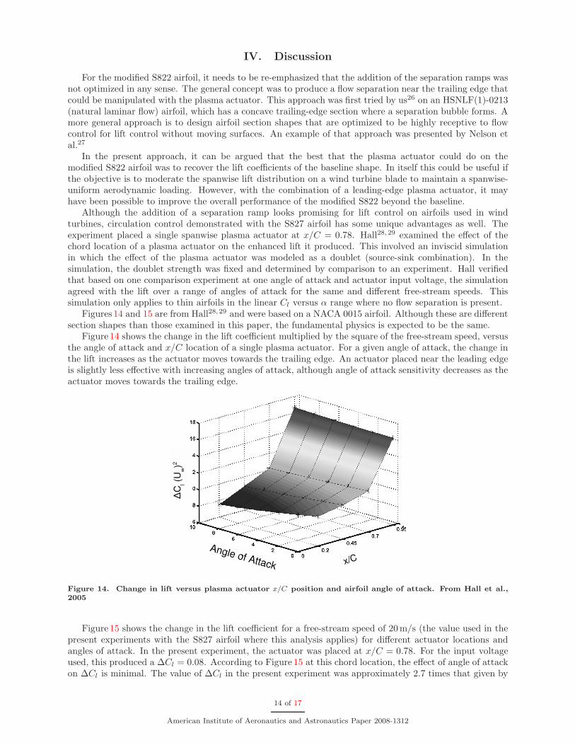
Figures 14 and 15 are from Hall28, 29 and were based on a NACA 0015 airfoil. Although these are differentsection shapes than those examined in this paper, the fundamental physics is expected to be the same.
Figure 14 shows the change in the lift coefficient multiplied by the square of the free-stream speed, versusthe angle of attack and x/C location of a single plasma actuator. For a given angle of attack, the change inthe lift increases as the actuator moves towards the trailing edge. An actuator placed near the leading edgeis slightly less effective with increasing angles of attack, although angle of attack sensitivity decreases as theactuator moves towards the trailing edge.
Figure 14. Change in lift versus plasma actuator x/C position and airfoil angle of attack. From Hall et al.,2005
Figure 15 shows the change in the lift coefficient for a free-stream speed of 20m/s (the value used in thepresent experiments with the S827 airfoil where this analysis applies) for different actuator locations andangles of attack. In the present experiment, the actuator was placed at x/C = 0.78. For the input voltageused, this produced a ∆Cl = 0.08. According to Figure 15 at this chord location, the effect of angle of attackon ∆Cl is minimal. The value of ∆Cl in the present experiment was approximately 2.7 times that given by
14 of 17
American Institute of Aeronautics and Astronautics Paper 2008-1312

Hall. However, the plasma actuator used in determining the doublet strength produced a significantly lowerbody force (see Iqbal33) by an amount that corresponded to the ratio of ∆Cl values. If we were to simplyre-scale ∆Cl values in Figure 15 it would provide an indication of the effect of the present plasma actuatorfor lift control.
Since the effect of multiple plasma actuators is additive, Figure 15 provides a guide for digital lift controlof the turbine rotor airfoil sections. For example if an actuator of present design located at x/C = 0.9 wereoperated simultaneously with the one at x/C = 0.78, the combined lift enhancement is predicted to be∆Cl = 0.08 + 0.99 = 0.18. If another actuator is added at x/C = 0.6, the total ∆Cl = 0.23. The total liftenhancement produced by three plasma actuators operating simultaneously would provide the equivalentof a 5.5◦ flap deflection of a trailing-edge flap with Cf/C = 0.1. The digital control comes by operatingmultiple numbers of actuators in different combinations to generate discrete changes in lift in response todynamically changing conditions. This is the premise behind the PACE rotor concept that was shown inFigure 3.
Figure 15. Change in lift versus plasma actuator x/C position at different airfoil angles of attack for U∞ =20 m/s. From Hall et al., 2005
V. Conclusions
SDBD plasma actuators were demonstrated in experiments to provide lift control on two wind turbineblade section shapes designated S827 and S822. For the S822 section shape, the objective was to modify thebaseline section shape to produce flow separation ramps that could be manipulated by the plasma actuatorsto produce different pressure distributions near the trailing edge, and thereby control the overall lift. Theramp sections were linear cuts having angles of 15◦ with respect to a line tangent to the surface at the airfoilmaximum thickness point. The overall length of the airfoil would remain the same as the baseline.
Without separation control at the ramps, the lift distribution with angle of attack of the modified S822airfoil fell below the baseline values. The maximum deviations occurring at approximately α = 3◦ and 11◦.The deviation at the smaller angles of attack were due to the flow separation over the ramps. At the higherangles of attack, the deviations were due to a premature leading edge separation. The plasma actuator couldrecover the lost lift at the lower angles of attack between −3◦ ≤ α ≤ 3◦. In this range, the maximum changein lift between having the plasma actuator on and off was approximately ∆Cl = 0.4. This is equivalent toa 10◦ deflection of a plane trailing-edge flap with a Cf/C = 0.1. This was performed with a periodically
15 of 17
American Institute of Aeronautics and Astronautics Paper 2008-1312

pulsed plasma actuator which reduced the power to the actuator by 90% over steady operation used for liftcontrol based on circulation control.
For the S827 section shape, the objective was to use steady plasma actuators for circulation control thathas been shown to be equivalent to increasing the effective camber of 2-D airfoil sections. A single plasmaactuator at x/C = 0.78 was investigated. The actuator resulted in a positive shift in the lift coefficient ofapproximately ∆Cl = 0.08. This corresponded to a change in the equivalent angle of attack of approximately∆α = 0.7◦, which was equivalent to a 2◦ deflection of a plane flap having a Cf/C = 0.10. The real potentialof this approach is in using multiple plasma actuators at different x/C locations. The effect of each ofthese actuators strongly depends on their chord locations and weakly depends on angle of attack. Howevertheir effect adds linearly so that for the conditions used in the experiments reported here, three actuatorsat x/C = 0.6, 0.78 and 0.9 would produce the equivalent of 5.5◦ flap deflection of a trailing-edge flap withCf/C = 0.1, or approximately 2.75 times larger than with the single actuator at x/C = 0.78.
The use of multiple actuators distributed at different chord location on the airfoil beautifully lends itself todigital control that would produce discrete changes in lift in response to dynamically changing rotor windconditions. This is the basis for the Plasma Aerodynamic Control Effectors (PACE) system for improvingwind turbine performance and control.
Acknowledgement
This research effort was supported by Orbital Research Inc. under a SBIR grant (DE-FG02-07ER84781)sponsored by the Department of Energy (DOE), under the direction of Dennis Lin, DOE Project Officer.
References
1American Wind Energy Association, Global Wind Energy Market Report, 2001.2Tangler, J. L. and Somers, D. M., NREL Airfoil Families for HAWTs, AWEA 95, March, 1995.3Corke, T., Post, M. and Orlov, D. 2007. SDBD plasma enhanced aerodynamics:
concepts, optimization and applications. Prog. Aerospace Sci., doi:10.1016/j.paerosci.2007.06.001, Elsevier Ltd.4Post, M. and T. Corke. 2003. Separation control on high angle of attack airfoil using plasma actuators. AIAA Paper
2003-1024, also 2006, AIAA J., 42, 11, p. 2177.5Huang, J., Corke, T. and Thomas, F. 2003. Plasma actuators for separation control of low pressure turbine blades. AIAA
Paper 2003-1027. AIAA J., 44, 1, pp. 51-58.6Huang, J., Corke, T. and Thomas, F. 2006. Unsteady plasma actuators for separation control of low pressure turbine
blades. AIAA J., 44, 7, pp. 1477-1487.7Post, M. 2004. Plasma actuators for separation control on stationary and oscillating wings. Ph.D Dissertation, University
of Notre Dame.8Post, M. and Corke, T. 2004. Separation control using plasma actuators - stationary and oscillating airfoils. AIAA Paper
2004-0841.9Corke, T., He, C. and Patel, M., 2004. Plasma flaps and slats: an application of weakly-ionized plasma actuators. AIAA
Paper 2004-2127.10Corke, T., E. Jumper, M. Post, D. Orlov, and T. McLaughlin. 2002. Application of weakly-ionized plasmas as wing
flow-control devices. AIAA Paper 2002-0350.11Corke, T., Mertz, B. and Patel, M. 2006. Plasma flow control optimized airfoil. AIAA Paper 2006-1208.12Lopera, J., Ng, T. T., Patel, M. P., Vasudevan, S., Santavicca, E., and Corke, T. C., Aerodynamic Control Using
Windward Surface Plasma Actuators on a Separation Ramp, Journal of Aircraft, Vol. 44, No. 6, pp. 1889-1895, Nov-Dec 2007.13Patel, M. P., Ng, T. T., Vasudevan, S., Corke, T. C., Post, M., McLaughlin, T. E., and Suchomel, C., Scaling Effects of
an Aerodynamic Plasma Actuator, AIAA Paper No. 2007-635, to appear in Journal of Aircraft.14Patel, M. P., Ng, T. T., Vasudevan, S., Corke, T. C., and He, C., Plasma Actuators for Hingeless Aerodynamic Control
of an Unmanned Air Vehicle, Journal of Aircraft, Vol. 44, No. 4, pp. 1264-1274, July-Aug 2007.15Patel, M. P., Sowle, Z. H., Corke, T. C., and He, C., Autonomous Sensing and Control of Wing Stall Using a Smart
Plasma Slat, Journal of Aircraft, Vol. 44, No. 2, pp. 516-527, March-April 2007.16Enloe, L, T. McLaughlin, VanDyken, Kachner, E. Jumper, and T. Corke. 2004. Mechanisms and Response of a single
dielectric barrier plasma actuator: Plasma morphology. AIAA J., 42, 3, p. 589. Also AIAA 2003-1021.17Enloe, L, T. McLaughlin, VanDyken, Kachner, E. Jumper, T. Corke.. M. Post, O. Haddad. 2004. Mechanisms and
Response of a single dielectric barrier plasma actuator: Geometric effects. AIAA J., 42, 3, p 585.18Orlov, D. and Corke, T. C., Numerical simulation of aerodynamic plasma actuator effects, AIAA Paper 2005-1083.19Orlov, D., Corke, T., and Patel, M. 2006. Electric circuit model for aerodynamic plasma actuator. AIAA-2006-1206.20Orlov, D. Modeling and simulation of single dielectric barrier discharge plasma actuators. Ph.D. University of Notre
Dame, 2006.
16 of 17
American Institute of Aeronautics and Astronautics Paper 2008-1312

21Miller, L. S., Quandt, G. A., Huang, S., Atmospheric Tests of Trailing-Edge Aerodynamic Devices, NREL SR -500-22350,1998.
22Stuart, J. G., Wright, A. D. and Butterfield, C. P., Considerations for an Integrated Wind Turbine Controls Capabilityat the National Wind Technology Center: An Aileron Control Case Study for Power Regulation and Load Mitigation, NREL -TP-440-21335, June 1996.
23van Kuik, G., Barlas, T., and van Bussel, G., Smart Rotor and Control Concepts. Von Karman Institute for FluidDynamics Lecture Series entitled wind Turbine Aerodynamics A State-of-the-Art, March 19-23, 2007.
24Somers, D. M., Design and Experimental Results for the S827 Airfoil, NREL/SR500-36345, January 2005.25Somers, D. M., The S822 and S823 Airfoils, NREL/SR-500-36342, January 2005.26Corke, T., Mertz, B. and Patel, M. Plasma flow control optimized airfoil, AIAA Paper 2006-1208.27Nelson, S., Cain, A., Patel, M., and Corke, T., A simplified strategy for optimizing flow-control-configured airfoils, AIAA
Paper 2007-4274-FCC.28Hall, K., Jumper, E., Corke, T. and McLaughlin, T. Potential flow model of a plasma actuator as a lift enhancement
device. AIAA Paper 2005-0783.29Hall, K. Potential flow model for plasma actuation as a lift enhancement device. M.S. Thesis, University of Notre Dame,
2004.30Corke, T. C., “Design of Aircraft”, Prentice-Hall Publishers, New York, 2002.31He, C., Corke, T. and Patel, M. Numerical and experimental analysis of plasma flow control over a hump model. AIAA
Paper 2007-0935.32He, C. Plasma slats and flaps: an application of plasma actuators for hingeless aerodynamic control. Ph.D. University of
Notre Dame. 2008.33Iqbal,M., Corke, T. and Thomas, F. Parametric optimization of single dielectric barrier discharge (SDBD) plasma actu-
ators. Submitted AIAA J., 2007.
17 of 17
American Institute of Aeronautics and Astronautics Paper 2008-1312


![, Allen, C., & Rendall, T. (2019). Efficient Aero-Structural Wing AIAA Scitech … · In AIAA Scitech 2019 Forum [AIAA 2019-1701] (AIAA Scitech 2019 Forum). American Institute of](https://img.pdfslide.us/doc/110x75/6089b44b26d0b4646a6cbe59/-allen-c-rendall-t-2019-efficient-aero-structural-wing-aiaa-scitech.jpg)