Embed Size (px)
Citation preview


AI-EXP48
Analog Input Expansion Module
User's Guide
Document Revision 1, August, 2007
© Copyright 2007, Measurement Computing Corporation
Your new Measurement Computing product comes with a fantastic extra —
Management committed to your satisfaction! Refer to www.mccdaq.com/execteam.html for the names, titles, and contact information of each key executive at Measurement Computing. Thank you for choosing a Measurement Computing product—and congratulations! You own the finest, and you can now enjoy the protection of the most comprehensive warranties and unmatched phone tech support. It’s the embodiment of our mission:
To provide PC-based data acquisition hardware and software that will save time and save money. Simple installations minimize the time between setting up your system and actually making measurements. We offer quick and simple access to outstanding live FREE technical support to help integrate MCC products into a DAQ system. Lifetime warranty: Every hardware product manufactured by Measurement Computing Corporation is warranted against defects in materials or workmanship for the life of the product. Products found defective are repaired or replaced promptly. Lifetime Harsh Environment Warranty®: We will replace any product manufactured by Measurement Computing Corporation that is damaged (even due to misuse) for only 50% of the current list price. I/O boards face some tough operating conditions, some more severe than the boards are designed to withstand. When a board becomes damaged, just return the unit with an order for its replacement at only 50% of the current list price. We don’t need to profit from your misfortune. By the way, we honor this warranty for any manufacturer’s board that we have a replacement for. 30 Day Money Back Guarantee: You may return any Measurement Computing Corporation product within 30 days of purchase for a full refund of the price paid for the product being returned. If you are not satisfied, or chose the wrong product by mistake, you do not have to keep it. Please call for an RMA number first. No credits or returns accepted without a copy of the original invoice. Some software products are subject to a repackaging fee. These warranties are in lieu of all other warranties, expressed or implied, including any implied warranty of merchantability or fitness for a particular application. The remedies provided herein are the buyer’s sole and exclusive remedies. Neither Measurement Computing Corporation, nor its employees shall be liable for any direct or indirect, special, incidental or consequential damage arising from the use of its products, even if Measurement Computing Corporation has been notified in advance of the possibility of such damages.
3 HM AI-EXP48.doc
Trademark and Copyright Information TracerDAQ, Universal Library, Harsh Environment Warranty, Measurement Computing Corporation, and the Measurement Computing logo are either trademarks or registered trademarks of Measurement Computing Corporation. Windows, Microsoft, and Visual Studio are either trademarks or registered trademarks of Microsoft Corporation LabVIEW is a trademark of National Instruments. CompactFlash is a registered trademark of SanDisk Corporation. XBee and XBee-PRO are trademarks of MaxStream, Inc. All other trademarks are the property of their respective owners. Information furnished by Measurement Computing Corporation is believed to be accurate and reliable. However, no responsibility is assumed by Measurement Computing Corporation neither for its use; nor for any infringements of patents or other rights of third parties, which may result from its use. No license is granted by implication or otherwise under any patent or copyrights of Measurement Computing Corporation. All rights reserved. No part of this publication may be reproduced, stored in a retrieval system, or transmitted, in any form by any means, electronic, mechanical, by photocopying, recording, or otherwise without the prior written permission of Measurement Computing Corporation.
Notice Measurement Computing Corporation does not authorize any Measurement Computing Corporation product for use in life support systems and/or devices without prior written consent from Measurement Computing Corporation. Life support devices/systems are devices or systems which, a) are intended for surgical implantation into the body, or b) support or sustain life and whose failure to perform can be reasonably expected to result in injury. Measurement Computing Corporation products are not designed with the components required, and are not subject to the testing required to ensure a level of reliability suitable for the treatment and diagnosis of people.
4
Table of Contents Preface About this User’s Guide .......................................................................................................................6
What you will learn from this user’s guide.........................................................................................................6 Conventions in this user’s guide.........................................................................................................................6 Where to find more information .........................................................................................................................6
Chapter 1 Introducing the AI-EXP48.....................................................................................................................7
Overview: AI-EXP48 features............................................................................................................................7 Software features ................................................................................................................................................7
Chapter 2 Installing the AI-EXP48.........................................................................................................................8
What comes with your AI-EXP48 shipment?.....................................................................................................8 Hardware .......................................................................................................................................................................... 8 Optional components ........................................................................................................................................................ 8 Additional documentation................................................................................................................................................. 8
Unpacking the AI-EXP48...................................................................................................................................8 Connecting to the parent A/D device with the DSUB25 expansion connector...................................................9 Connecting the device for I/O operations .........................................................................................................10
User connectors................................................................................................................................................................10 Screw terminal pin out .....................................................................................................................................................11 Expansion connector........................................................................................................................................................12 Cabling.............................................................................................................................................................................13
Associating CJC channels with thermocouple channels...................................................................................13 Chapter 3 Specifications......................................................................................................................................14
Analog input .....................................................................................................................................................14 Accuracy..........................................................................................................................................................................14 Thermocouples ................................................................................................................................................................14
Power consumption ..........................................................................................................................................15 Environmental ..................................................................................................................................................15 Mechanical .......................................................................................................................................................15 User connectors ................................................................................................................................................15
Declaration of Conformity ..................................................................................................................18
5
Preface
About this User’s Guide
What you will learn from this user’s guide This user’s guide explains how to install, configure, and use the AI-EXP48 so that you get the most out of its analog input features.
This user’s guide also refers you to related documents available on our web site, and to technical support resources.
Conventions in this user’s guide For more information on … Text presented in a box signifies additional information and helpful hints related to the subject matter you are reading.
Caution! Shaded caution statements present information to help you avoid injuring yourself and others, damaging your hardware, or losing your data.
<#:#> Angle brackets that enclose numbers separated by a colon signify a range of numbers, such as those assigned to registers, bit settings, etc.
bold text Bold text is used for the names of objects on the screen, such as buttons, text boxes, and check boxes. For example: 1. Insert the disk or CD and click the OK button.
italic text Italic text is used for the names of manuals and help topic titles, and to emphasize a word or phrase. For example: The InstaCal installation procedure is explained in the Quick Start Guide. Never touch the exposed pins or circuit connections on the board.
Where to find more information The following electronic documents provide helpful information relevant to the operation of the AI-EXP48.
MCC's Specifications: AI-EXP48 (the PDF version of the Specifications chapter in this guide) is available on our web site at www.mccdaq.com/pdfs/AI-EXP48.pdf.
MCC's Quick Start Guide is available on our web site at www.mccdaq.com/PDFmanuals/DAQ-Software-Quick-Start.pdf.
MCC's Guide to Signal Connections is available on our web site at www.mccdaq.com/signals/signals.pdf.
MCC's Universal Library User's Guide is available on our web site at www.mccdaq.com/PDFmanuals/sm-ul-user-guide.pdf.
MCC's Universal Library Function Reference is available on our web site at www.mccdaq.com/PDFmanuals/sm-ul-functions.pdf.
MCC's Universal Library for LabVIEW™ User’s Guide is available on our web site at www.mccdaq.com/PDFmanuals/SM-UL-LabVIEW.pdf.
AI-EXP48 User's Guide (this document) is also available on our web site at www.mccdaq.com/PDFmanuals/AI-EXP48.pdf.
6
Chapter 1
Introducing the AI-EXP48
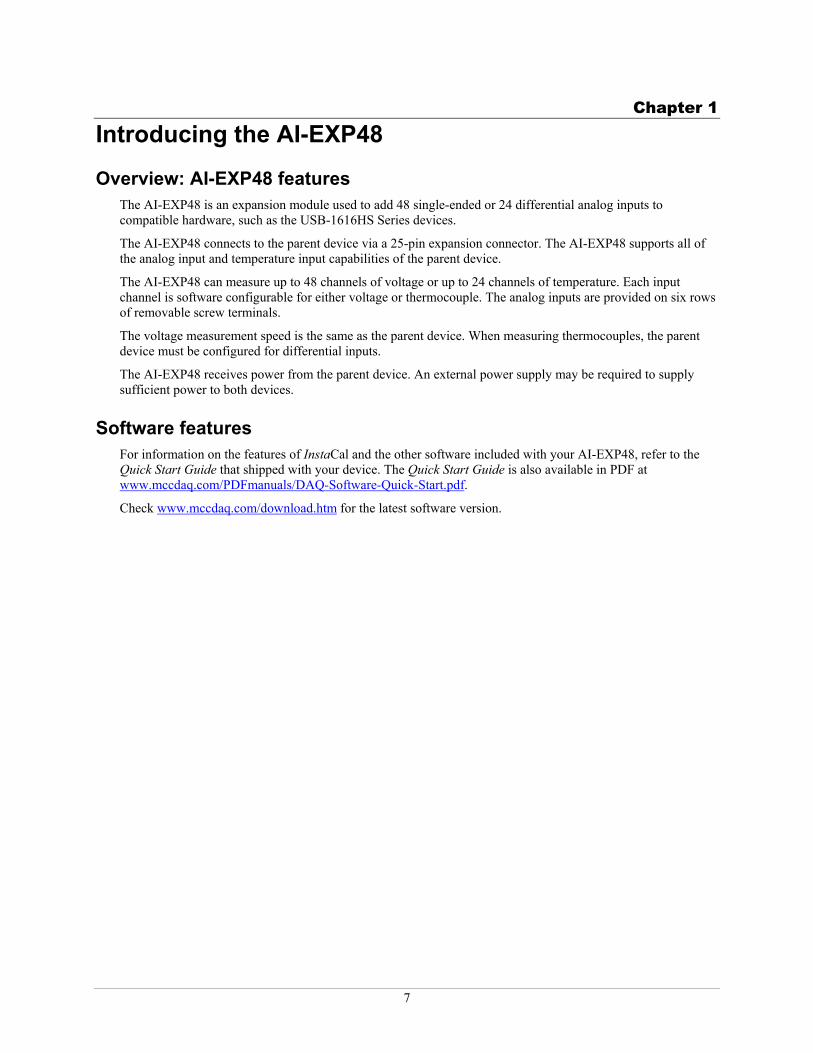
Overview: AI-EXP48 features The AI-EXP48 is an expansion module used to add 48 single-ended or 24 differential analog inputs to compatible hardware, such as the USB-1616HS Series devices.
The AI-EXP48 connects to the parent device via a 25-pin expansion connector. The AI-EXP48 supports all of the analog input and temperature input capabilities of the parent device.
The AI-EXP48 can measure up to 48 channels of voltage or up to 24 channels of temperature. Each input channel is software configurable for either voltage or thermocouple. The analog inputs are provided on six rows of removable screw terminals.
The voltage measurement speed is the same as the parent device. When measuring thermocouples, the parent device must be configured for differential inputs.
The AI-EXP48 receives power from the parent device. An external power supply may be required to supply sufficient power to both devices.
Software features For information on the features of InstaCal and the other software included with your AI-EXP48, refer to the Quick Start Guide that shipped with your device. The Quick Start Guide is also available in PDF at www.mccdaq.com/PDFmanuals/DAQ-Software-Quick-Start.pdf.
Check www.mccdaq.com/download.htm for the latest software version.
7
Chapter 2
Installing the AI-EXP48
What comes with your AI-EXP48 shipment? The following items are shipped with the AI-EXP48.
Hardware AI-EXP48
Clips (2) used to lock the AI-EXP48 and parent device together when connected directly
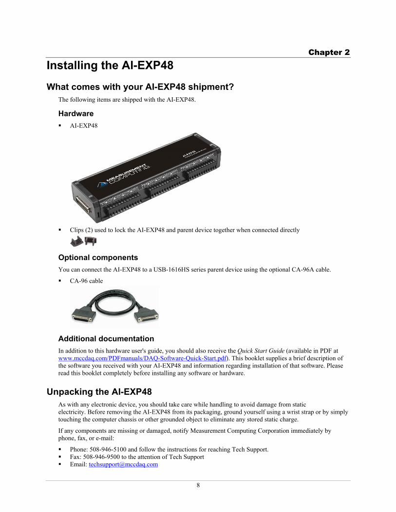
Optional components You can connect the AI-EXP48 to a USB-1616HS series parent device using the optional CA-96A cable.
CA-96 cable
Additional documentation In addition to this hardware user's guide, you should also receive the Quick Start Guide (available in PDF at www.mccdaq.com/PDFmanuals/DAQ-Software-Quick-Start.pdf). This booklet supplies a brief description of the software you received with your AI-EXP48 and information regarding installation of that software. Please read this booklet completely before installing any software or hardware.
Unpacking the AI-EXP48 As with any electronic device, you should take care while handling to avoid damage from static electricity. Before removing the AI-EXP48 from its packaging, ground yourself using a wrist strap or by simply touching the computer chassis or other grounded object to eliminate any stored static charge.
If any components are missing or damaged, notify Measurement Computing Corporation immediately by phone, fax, or e-mail:
Phone: 508-946-5100 and follow the instructions for reaching Tech Support. Fax: 508-946-9500 to the attention of Tech Support Email: [email protected]
8
AI-EXP48 User's Guide Installing the AI-EXP48
Connecting to the parent A/D device with the DSUB25 expansion connector
You can use the 25-pin expansion connector to connect to a compatible parent device, such as a USB-1616HS Series device.
You can either mate the expansion connectors directly or use the optional expansion cable to connect the two devices. Do the following:
1.
2. o
Disconnect the USB cable from the parent device. If the parent device is connected to an external power supply, remove the external power cable from the device. Connect the two devices together by one of the following methods:
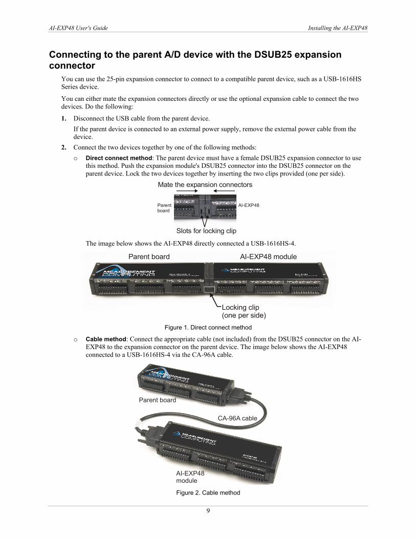
Direct connect method: The parent device must have a female DSUB25 expansion connector to use this method. Push the expansion module's DSUB25 connector into the DSUB25 connector on the parent device. Lock the two devices together by inserting the two clips provided (one per side).
Mate the expansion connectors
Slots for locking clip
Parentboard
AI-EXP48
The image below shows the AI-EXP48 directly connected a USB-1616HS-4.
Parent board AI-EXP48 module
Locking clip(one per side)
Figure 1. Direct connect method
o Cable method: Connect the appropriate cable (not included) from the DSUB25 connector on the AI-EXP48 to the expansion connector on the parent device. The image below shows the AI-EXP48 connected to a USB-1616HS-4 via the CA-96A cable.
Parent board
AI-EXP48module
CA-96A cable
Figure 2. Cable method
9
AI-EXP48 User's Guide Installing the AI-EXP48
3.
4.
Connect the external power supply, if used, to the power input port of the parent device, and then plug it into an AC outlet. Note: Connecting external power to the device before connecting the USB cable to the computer allows the parent device to inform the host computer upon connection of the USB cable that the device requires minimum power from the computer's USB port. Connect the USB cable from the parent device to the host computer's USB port. Connect to a USB 2.0 high speed hub to achieve the highest transfer rate (480 Mbps). When connected to a USB 1.1 full-speed port, the transfer rate is limited to 12 Mbps.
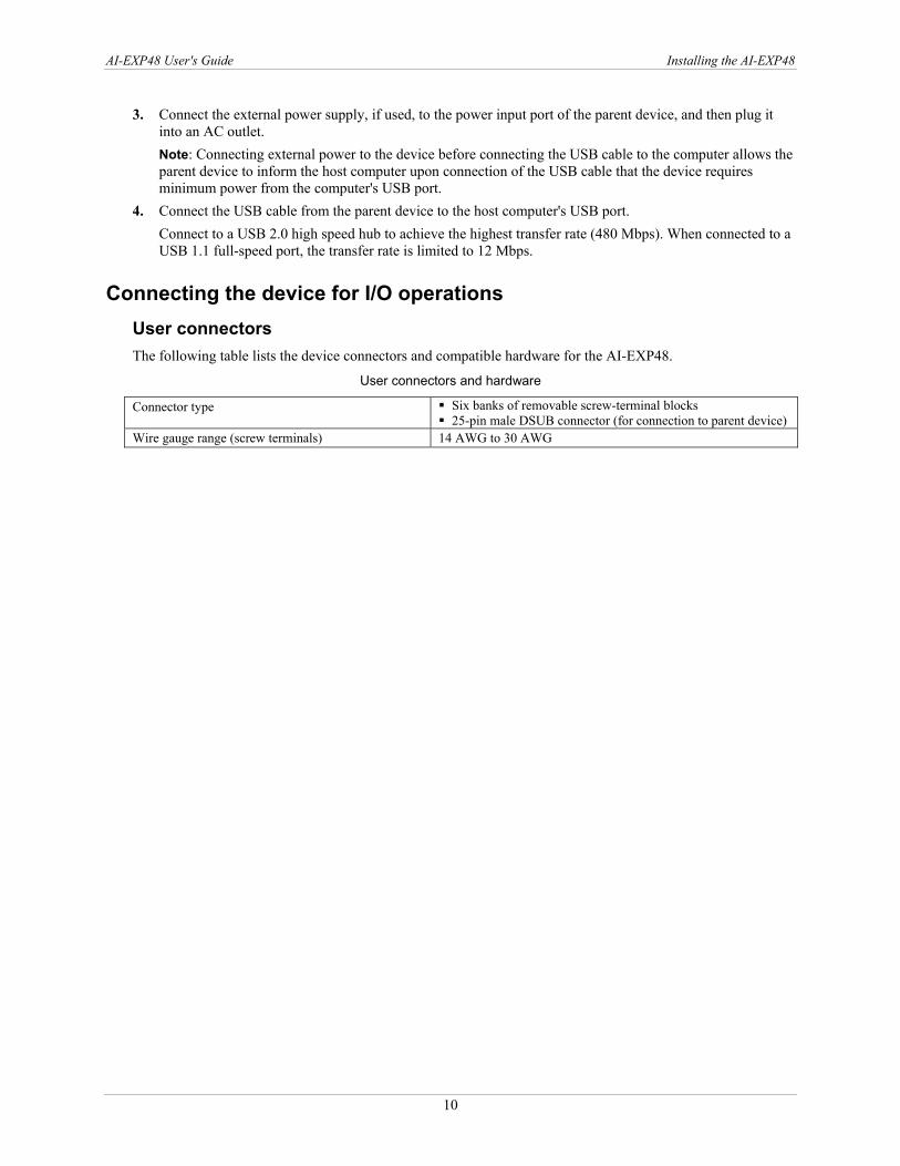
Connecting the device for I/O operations User connectors The following table lists the device connectors and compatible hardware for the AI-EXP48.
User connectors and hardware
Connector type Six banks of removable screw-terminal blocks 25-pin male DSUB connector (for connection to parent device)
Wire gauge range (screw terminals) 14 AWG to 30 AWG
10
AI-EXP48 User's Guide Installing the AI-EXP48
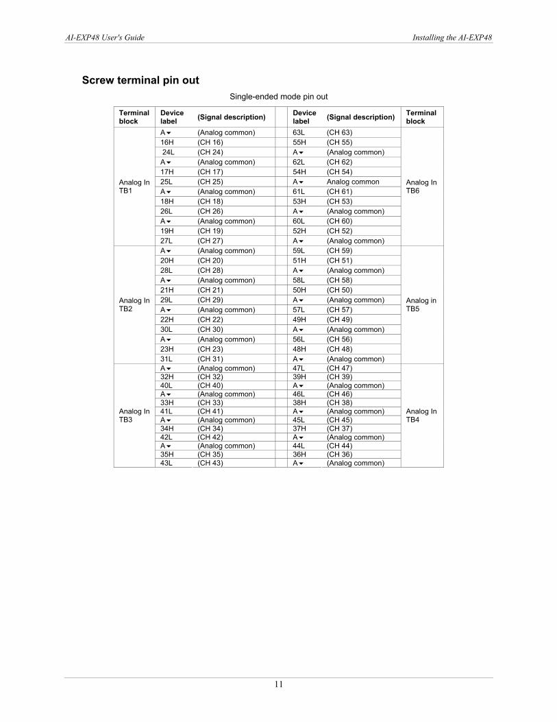
Screw terminal pin out Single-ended mode pin out
Terminal block
Device label (Signal description) Device
label (Signal description) Terminal block
A (Analog common) 63L (CH 63) 16H (CH 16) 55H (CH 55) 24L (CH 24) A (Analog common) A (Analog common) 62L (CH 62) 17H (CH 17) 54H (CH 54) 25L (CH 25) A Analog common A (Analog common) 61L (CH 61) 18H (CH 18) 53H (CH 53) 26L (CH 26) A (Analog common) A (Analog common) 60L (CH 60) 19H (CH 19) 52H (CH 52)
Analog In TB1
27L (CH 27) A (Analog common)
Analog In TB6
A (Analog common) 59L (CH 59) 20H (CH 20) 51H (CH 51) 28L (CH 28) A (Analog common) A (Analog common) 58L (CH 58) 21H (CH 21) 50H (CH 50) 29L (CH 29) A (Analog common) A (Analog common) 57L (CH 57) 22H (CH 22) 49H (CH 49) 30L (CH 30) A (Analog common) A (Analog common) 56L (CH 56) 23H (CH 23) 48H (CH 48)
Analog In TB2
31L (CH 31) A (Analog common)
Analog in TB5
A (Analog common) 47L (CH 47) 32H (CH 32) 39H (CH 39) 40L (CH 40) A (Analog common) A (Analog common) 46L (CH 46) 33H (CH 33) 38H (CH 38) 41L (CH 41) A (Analog common) A (Analog common) 45L (CH 45) 34H (CH 34) 37H (CH 37) 42L (CH 42) A (Analog common) A (Analog common) 44L (CH 44) 35H (CH 35) 36H (CH 36)
Analog In TB3
43L (CH 43) A (Analog common)
Analog In TB4
11
AI-EXP48 User's Guide Installing the AI-EXP48
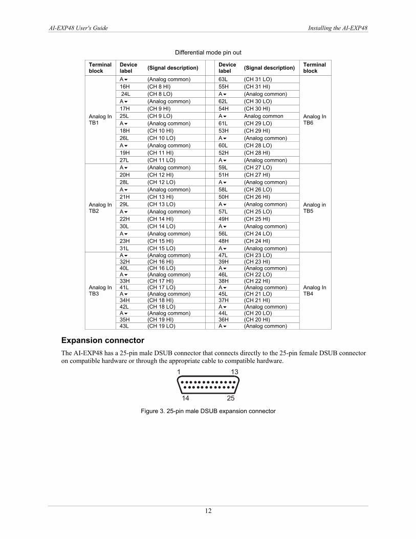
Differential mode pin out
Terminal block
Device label (Signal description) Device
label (Signal description) Terminal block
A (Analog common) 63L (CH 31 LO) 16H (CH 8 HI) 55H (CH 31 HI) 24L (CH 8 LO) A (Analog common) A (Analog common) 62L (CH 30 LO) 17H (CH 9 HI) 54H (CH 30 HI) 25L (CH 9 LO) A Analog common A (Analog common) 61L (CH 29 LO) 18H (CH 10 HI) 53H (CH 29 HI) 26L (CH 10 LO) A (Analog common) A (Analog common) 60L (CH 28 LO) 19H (CH 11 HI) 52H (CH 28 HI)
Analog In TB1
27L (CH 11 LO) A (Analog common)
Analog In TB6
A (Analog common) 59L (CH 27 LO) 20H (CH 12 HI) 51H (CH 27 HI) 28L (CH 12 LO) A (Analog common) A (Analog common) 58L (CH 26 LO) 21H (CH 13 HI) 50H (CH 26 HI) 29L (CH 13 LO) A (Analog common) A (Analog common) 57L (CH 25 LO) 22H (CH 14 HI) 49H (CH 25 HI) 30L (CH 14 LO) A (Analog common) A (Analog common) 56L (CH 24 LO) 23H (CH 15 HI) 48H (CH 24 HI)
Analog In TB2
31L (CH 15 LO) A (Analog common)
Analog in TB5
A (Analog common) 47L (CH 23 LO) 32H (CH 16 HI) 39H (CH 23 HI) 40L (CH 16 LO) A (Analog common) A (Analog common) 46L (CH 22 LO) 33H (CH 17 HI) 38H (CH 22 HI) 41L (CH 17 LO) A (Analog common) A (Analog common) 45L (CH 21 LO) 34H (CH 18 HI) 37H (CH 21 HI) 42L (CH 18 LO) A (Analog common) A (Analog common) 44L (CH 20 LO) 35H (CH 19 HI) 36H (CH 20 HI)
Analog In TB3
43L (CH 19 LO) A (Analog common)
Analog In TB4
Expansion connector The AI-EXP48 has a 25-pin male DSUB connector that connects directly to the 25-pin female DSUB connector on compatible hardware or through the appropriate cable to compatible hardware.
1 1
14 25
3
Figure 3. 25-pin male DSUB expansion connector
12
AI-EXP48 User's Guide Installing the AI-EXP48
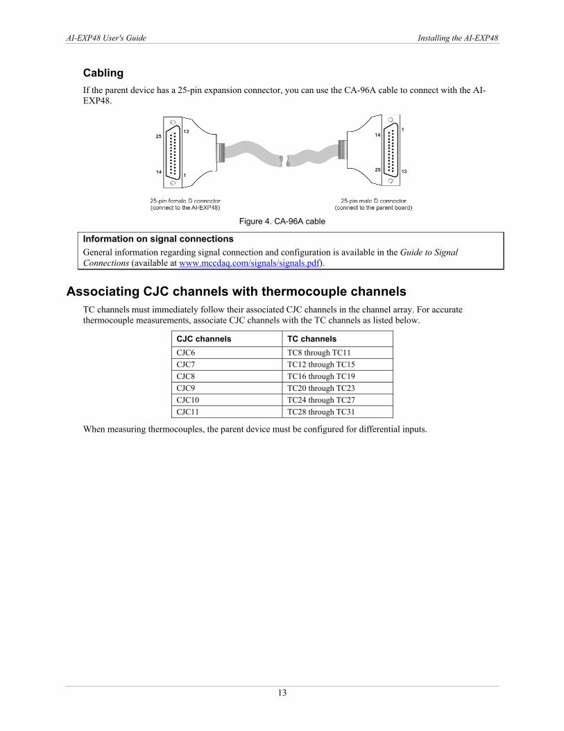
Cabling If the parent device has a 25-pin expansion connector, you can use the CA-96A cable to connect with the AI-EXP48.
Figure 4. CA-96A cable
Information on signal connections General information regarding signal connection and configuration is available in the Guide to Signal Connections (available at www.mccdaq.com/signals/signals.pdf).
Associating CJC channels with thermocouple channels TC channels must immediately follow their associated CJC channels in the channel array. For accurate thermocouple measurements, associate CJC channels with the TC channels as listed below.
CJC channels TC channels CJC6 TC8 through TC11 CJC7 TC12 through TC15 CJC8 TC16 through TC19 CJC9 TC20 through TC23 CJC10 TC24 through TC27 CJC11 TC28 through TC31
When measuring thermocouples, the parent device must be configured for differential inputs.
13

Chapter 3
Specifications Typical for 25 °C unless otherwise specified. Specifications in italic text are guaranteed by design.
Analog input Table 1. Analog input specifications
Number of channels 48 single-ended/24 differential inputs Voltage measurement speed 1 µs per channel Input ranges, software or sequencer programmable Bipolar: ±10 V, ±5 V, ±2 V, ±1 V , ±0.5 V, ±0.2 V, ±0.1 V,
universal thermocouple Signal to noise and distortion 72 dB typical for ±10 V range, 1 kHz fundamental Total harmonic distortion -80 dB typical for ±10 V range, 1 kHz fundamental Bias current 40 pA typical (0 °C to 35 °C) Crosstalk -75 dB DC to 60 Hz; -65 dB @ 10 kHz, typical Input impedance 10 MΩ single-ended, 20 MΩ differential Over-voltage protection ±30 V
Accuracy Table 2. Analog input accuracy specifications
Voltage range (note 1)
Accuracy ±(% of reading + % range) 23°C ±10 °C, 1 year
Temperature coefficient ±(ppm of reading + ppm range)/°C
Noise (cts RMS) (note 2)
-10 V to 10 V 0.031% + 0.008% 14 + 8 2.0 -5 V to 5 V 0.031% + 0.009% 14 + 9 3.0 -2 V to 2 V 0.031% + 0.010% 14 + 10 2.0 -1 V to 1 V 0.031% + 0.02% 14 + 12 3.5 -500 mV to 500 mV 0.031% + 0.04% 14 + 18 5.5 -200 mV to 200 mV 0.036% + 0.05% 14 + 12 8.0 -100 mV to 100 mV 0.042% + 0.10% 14 + 18 14.0
Note 1:
Note 2:
Specifications assume differential input single-channel scan, 1 MHz scan rate, unfiltered, CMV=0.0 V, 30 minute warm-up, exclusive of noise, -FS to +FS. Noise reflects 10,000 samples at 1 MHz, typical, differential short
Thermocouples Table 3. TC types and accuracy (Note 3)
TC type Temperature range (°C) Accuracy (±°C) Noise typical (±°C) J -200 to + 760 1.7 0.2 K -200 to + 1200 1.8 0.2 T -200 to + 400 1.8 0.2 E -270 to + 650 1.7 0.2 R -50 to + 1768 4.8 1.5 S -50 to + 1768 4.7 1.5 N -270 to + 1300 2.7 0.3 B +300 to + 1400 3.0 1.0
Note 3: Assumes 16384 oversampling applied, CMV = 0.0V, 60 minute warm-up, still environment, and 25 °C ambient temperature; excludes thermocouple error; TCin = 0° C for all types except B (1000 °C)
14
AI-EXP48 User's Guide Specifications
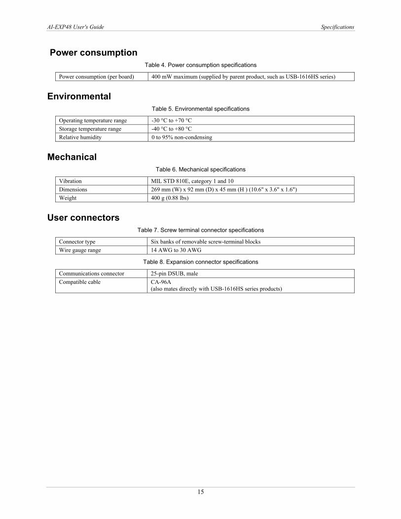
Power consumption Table 4. Power consumption specifications
Power consumption (per board) 400 mW maximum (supplied by parent product, such as USB-1616HS series)
Environmental Table 5. Environmental specifications
Operating temperature range -30 °C to +70 °C Storage temperature range -40 °C to +80 °C Relative humidity 0 to 95% non-condensing
Mechanical Table 6. Mechanical specifications
Vibration MIL STD 810E, category 1 and 10 Dimensions 269 mm (W) x 92 mm (D) x 45 mm (H ) (10.6" x 3.6" x 1.6") Weight 400 g (0.88 lbs)
User connectors Table 7. Screw terminal connector specifications
Connector type Six banks of removable screw-terminal blocks Wire gauge range 14 AWG to 30 AWG
Table 8. Expansion connector specifications
Communications connector 25-pin DSUB, male Compatible cable CA-96A
(also mates directly with USB-1616HS series products)
15
AI-EXP48 User's Guide Specifications
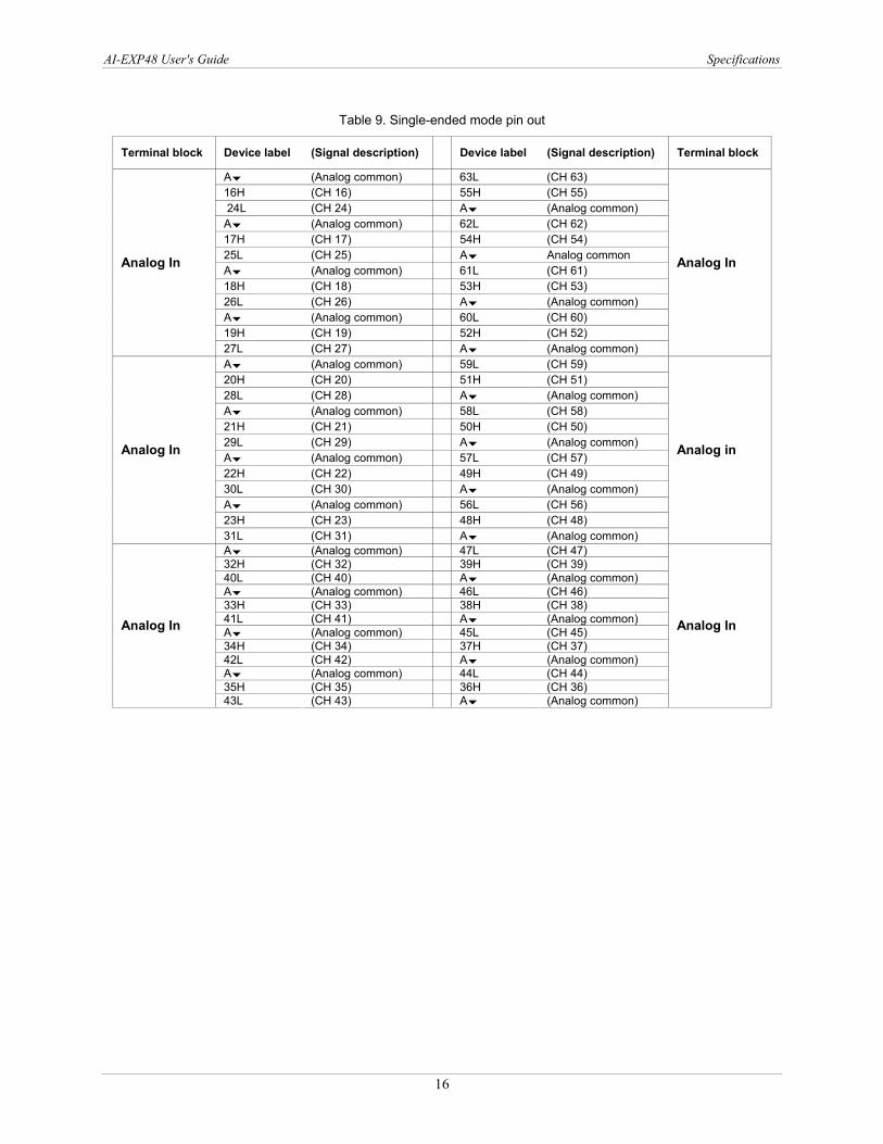
Table 9. Single-ended mode pin out
Terminal block Device label (Signal description) Device label (Signal description) Terminal block
A (Analog common) 63L (CH 63) 16H (CH 16) 55H (CH 55) 24L (CH 24) A (Analog common) A (Analog common) 62L (CH 62) 17H (CH 17) 54H (CH 54) 25L (CH 25) A Analog common A (Analog common) 61L (CH 61) 18H (CH 18) 53H (CH 53) 26L (CH 26) A (Analog common) A (Analog common) 60L (CH 60) 19H (CH 19) 52H (CH 52)
Analog In
27L (CH 27) A (Analog common)
Analog In
A (Analog common) 59L (CH 59) 20H (CH 20) 51H (CH 51) 28L (CH 28) A (Analog common) A (Analog common) 58L (CH 58) 21H (CH 21) 50H (CH 50) 29L (CH 29) A (Analog common) A (Analog common) 57L (CH 57) 22H (CH 22) 49H (CH 49) 30L (CH 30) A (Analog common) A (Analog common) 56L (CH 56) 23H (CH 23) 48H (CH 48)
Analog In
31L (CH 31) A (Analog common)
Analog in
A (Analog common) 47L (CH 47) 32H (CH 32) 39H (CH 39) 40L (CH 40) A (Analog common) A (Analog common) 46L (CH 46) 33H (CH 33) 38H (CH 38) 41L (CH 41) A (Analog common) A (Analog common) 45L (CH 45) 34H (CH 34) 37H (CH 37) 42L (CH 42) A (Analog common) A (Analog common) 44L (CH 44) 35H (CH 35) 36H (CH 36)
Analog In
43L (CH 43) A (Analog common)
Analog In
16
AI-EXP48 User's Guide Specifications
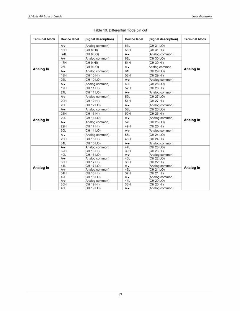
Table 10. Differential mode pin out
Terminal block Device label (Signal description) Device label (Signal description) Terminal block
A (Analog common) 63L (CH 31 LO) 16H (CH 8 HI) 55H (CH 31 HI) 24L (CH 8 LO) A (Analog common) A (Analog common) 62L (CH 30 LO) 17H (CH 9 HI) 54H (CH 30 HI) 25L (CH 9 LO) A Analog common A (Analog common) 61L (CH 29 LO) 18H (CH 10 HI) 53H (CH 29 HI) 26L (CH 10 LO) A (Analog common) A (Analog common) 60L (CH 28 LO) 19H (CH 11 HI) 52H (CH 28 HI)
Analog In
27L (CH 11 LO) A (Analog common)
Analog In
A (Analog common) 59L (CH 27 LO) 20H (CH 12 HI) 51H (CH 27 HI) 28L (CH 12 LO) A (Analog common) A (Analog common) 58L (CH 26 LO) 21H (CH 13 HI) 50H (CH 26 HI) 29L (CH 13 LO) A (Analog common) A (Analog common) 57L (CH 25 LO) 22H (CH 14 HI) 49H (CH 25 HI) 30L (CH 14 LO) A (Analog common) A (Analog common) 56L (CH 24 LO) 23H (CH 15 HI) 48H (CH 24 HI)
Analog In
31L (CH 15 LO) A (Analog common)
Analog in
A (Analog common) 47L (CH 23 LO) 32H (CH 16 HI) 39H (CH 23 HI) 40L (CH 16 LO) A (Analog common) A (Analog common) 46L (CH 22 LO) 33H (CH 17 HI) 38H (CH 22 HI) 41L (CH 17 LO) A (Analog common) A (Analog common) 45L (CH 21 LO) 34H (CH 18 HI) 37H (CH 21 HI) 42L (CH 18 LO) A (Analog common) A (Analog common) 44L (CH 20 LO) 35H (CH 19 HI) 36H (CH 20 HI)
Analog In
43L (CH 19 LO) A (Analog common)
Analog In
17
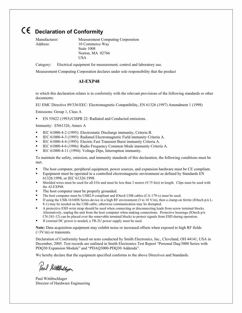
Declaration of Conformity Manufacturer: surement Computing Corporation MeaAddress: 10 Commerce Way Suite 1008 Norton, MA 02766 USA
Category: Electrical equipment for measurement, control and laboratory use.
Measurement Computing Corporation declares under sole responsibility that the product
AI-EXP48
to which this declaration relates is in conformity with the relevant provisions of the following standards or other documents:
EU EMC Directive 89/336/EEC: Electromagnetic Compatibility, EN 61326 (1997) Amendment 1 (1998)
Emissions: Group 1, Class A
EN 55022 (1993)/CISPR 22: Radiated and Conducted emissions.
Immunity: EN61326, Annex A
IEC 61000-4-2 (1995): Electrostatic Discharge immunity, Criteria B. IEC 61000-4-3 (1995): Radiated Electromagnetic Field immunity Criteria A. IEC 61000-4-4 (1995): Electric Fast Transient Burst immunity Criteria A. IEC 61000-4-6 (1996): Radio Frequency Common Mode immunity Criteria A. IEC 61000-4-11 (1994): Voltage Dips, Interruption immunity.
To maintain the safety, emission, and immunity standards of this declaration, the following conditions must be met.
The host computer, peripheral equipment, power sources, and expansion hardware must be CE compliant. Equipment must be operated in a controlled electromagnetic environment as defined by Standards EN
61326:1998, or IEC 61326:1998. Shielded wires must be used for all I/Os and must be less than 3 meters (9.75 feet) in length. Clips must be used with
the AI-EXP48. The host computer must be properly grounded. The host computer must be USB2.0 compliant and IOtech USB cables (CA-179-x) must be used. If using the USB-1616HS Series device in a high RF environment (3 to 10 V/m), then a clamp-on ferrite (IOtech p/n L-
8-1) may be needed on the USB cable, otherwise communication may be disrupted. A protective ESD wrist strap should be used when connecting or disconnecting leads from screw terminal blocks.
Alternatively, unplug the unit from the host computer when making connections. Protective housings (IOtech p/n CN-241-12) can be placed over the removable terminal blocks to protect signals from ESD during operation.
If external DC power is needed, a TR-2U power supply must be used.
Note: Data acquisition equipment may exhibit noise or increased offsets when exposed to high RF fields (>3V/m) or transients.
Declaration of Conformity based on tests conducted by Smith Electronics, Inc., Cleveland, OH 44141, USA in December, 2005. Test records are outlined in Smith Electronics Test Report “Personal Daq/3000 Series with PDQ30 Expansion Module” and “PDAQ3000-PDQ30 Addenda”.
We hereby declare that the equipment specified conforms to the above Directives and Standards.
Paul Wittibschlager Director of Hardware Engineering

Measurement Computing Corporation 10 Commerce Way
Suite 1008 Norton, Massachusetts 02766
(508) 946-5100 Fax: (508) 946-9500
E-mail: [email protected]