Embed Size (px)
Citation preview
a) Attendance 10%
b)
Lab reports
20%
c)
Viva
20%
d)
Quiz (End of semester)
50%
Total
100%
3.
Students must bring the
necessary instruments, data sheet (for particular experiment),
calculator, normal graph paper.
4.
Report should be submitted in the following week during the sessional time.
5.
Write report on one side of an 80 gms A4 paper and follow the following format
a)
Top sheet
b)
Objectives
c)
Apparatus (including technical specifications)
d)
Figure/Experimental Setup
e)
Data Sheets/Result
f)
Sample calculation
g)
Graphs
h)
Discussion
i)
Discuss the graphs and results
ii)
Discuss about the experimental setup if it could be improved
iii)
Discuss the different parameters that could affect the result
iv)
Discuss any assumption made
v)
Discuss any discrepancies in the experimental procedure and result
vi)
Discuss what you have learnt and the practical application of this
knowledge
AHSANULLAH UNIVERSITY OF SCIENCE & TECHNOLOGY
Department of Mechanical and Production Engineering
ME 2102: Basic Thermodynamics Sessional(Applied Thermodynamics Laboratory: 8B01)
List of the Experiments
1. Determination of Heating Value of Coal by Bomb Calorimeter
2. a) Analysis of Air using Orsat Gas Analyzer
b) Flash Point and Fire point of Fuel (kerosene oil)
3. a) Study of Psychrometer and determination of humidity of air using Sling Psychrometer
b) Calibration of a Pressure Gauge
4. Determination of Carbon Residue of an Oil (Conradson Method)
General Instructions1. Attend to the lab 5 minutes prior to the scheduled time.
2. Sessional grade will be calculated in the following way:

ME 2102: Basic Thermodynamics Sessional 2
Experiment No.: 1
Determination of Heating Value of Coal by Bomb Calorimeter
Objectives: To find the heating value of coal experimentally using a bomb calorimeter
Apparatus: Bomb Calorimeter, Thermometer, Stop Watch, Analytic Balance, Fuse Wire, Water Container
etc.
Description: The so called bomb calorimeter is used to determine the heating value of fuel when burned at
constant volume. The fuel whose heating values is desired is placed in the fuel pan (crucible). A
coil of fine wire dips in the pan. The bomb is charged with oxygen under pressure. When an
electric current is passed through the wire, it ignites the fuel. Surrounding the bomb is a bucket
containing water to absorb the heat released as the fuel burn. The bomb has an outer jacket, and a
dead-air space surrounds the bucket to minimize heat losses to the surroundings. Although the
water in the bucket absorbs the major portion of the heat, this heat is not the heating value of the
fuel, for the following reasons:
1. The bomb itself absorbs some heat
2. There is heat exchange with the outer jacket
3. The ignition wire liberates some energy
4. The product of combustion are not cooled to the original temperature
5. Because combustion takes place in oxygen, high temperature is attained resulting in the
formation of nitric and sulfuring acid, which would not be formed in the normal
combustion process.
It is true that the products of combustion are not cooled to the original temperature. However, the
final and original temperatures are so close that the error is only a small fraction of 1%.
Furthermore the error is almost entirely offset when the bomb is standardized. The “water
equivalent” of the bomb is furnished by the manufacturer. This is the amount of water having the
same thermal capacity as the bomb is furnished by the manufacturer. This is the amount of water
having the same thermal capacity as the bomb and its bucket (empty). When there is a doubt
about the validity of this value, the bomb should be standardized.
The exchange of heat with outer jacket is minimized by maintaining a minimum temperature
difference between the two. Corrections are made for small amount of heat transfer which occurs
due to radiation. Corrections are also made for the heat liberated by the ignition wire by
determining the amount actually burned. In the absence of exact heating value to the fuse wire, a
value of 2.3 cal/cm of wire may be used.
ME 2102: Basic Thermodynamics Sessional 3
Operations: 1. Weigh the calorimeter bucket empty. Put into calorimeter 1900 gm of water, having a
temperature of about 3C below the temperature in the jacket (It is assumed that the
jacket is at room temperature)
2. Make certain that interior of the bomb is clear. Clean up the holdes in the removable
lining with those in the bomb. Place the lower half of the bomb in the iron plate holder.
3. Insert the tapered pin and its crucible holder.
4. Obtain a true sample of coal and place approximately 1 gm of coal in the crucible, weigh
and place it in the bomb.
5. Select the proper type of fuse wire, measure the length and install it in the form of a coil.
The coil should touch the coal but not the crucible.
6. Add a few drops (about 0.5 ml) of water at the bottom of the bomb to saturate the space.
This will cause complete condensation of the water vapor of combustion and the heating
value obtained will be the higher heating value.
7. Place the gasket in place making certain that there is no dirt present. Assemble the bomb
and tighten the cap. Be careful not to spill the fuel out of the crucible by tipping or
jarking the bomb.
8. Charge the bomb with oxygen to a pressure of approximately 300 psi. Open the charging
valve very slowly to avoid blowing of coal from the crucible.
9. Immerse the bomb in water; preferably in a glass jar, to see whether there are any leaks.
The bomb should be dried with a cloth and placed it in the bomb jacket. The thermometer
and stirrer should be installed. The thermometer should be immersed in at least 3 inch. Of
water and should not be no closer than ½ inch to the bomb.
10. Start the stirrer. After 3 to 4 min for temperature equalization of water in the bucket, take
temperature readings every minute for 5 min. These temperature readings are required for
calculating the heat exchange with the jacket.
11. Switch on the firing switch for an instant.
12. Record the temperature according to data sheet until the maximum temperature is
reached. The observer of the thermometer must be alert, because a rapid temperature rise
occurs shortly after firing occurs.
13. After reaching the maximum temperature, temperature should be read every minute for 5
min. These temperatures are required in accounting for the heat exchange with the jacket
water.
14. Remove the bomb from calorimeter, release the gases, and disassemble bomb. Collect
and measure the length of the fuse wire which remains.
15. When accurate results are required, the bomb should be washed with distilled water and
the washing should be titrated to obtain the amount of acid formed.
Heat loss by radiation from the calorimeter is minimized by starting the determination with the
water in the calorimeter enough below room temperature so that the final temperature after
combustion will be slightly above room temperature. Thus the radiation from the room before
ignition will tend to compensate that to the room after the temperature rise. Since an appreciable
amount of time elapses before the rise in temperature is completed, there will be some heat
transfer in spite of this precaution.
ME 2102: Basic Thermodynamics Sessional 4
The Dickinson method of correction for radiation is prescribed by the ASTM. The rate of
temperature change in degree per minute is determined over a 5 min. period just before ignition
and again after ignition when the maximum temperature has been reached. The time of ignition
(time a), the temperature at ignition, the thermometer reading taken when the temperature change
has become uniform after attaining a maximum and the time at this maximum temperature (time
c) are recorded. Time b is defined as the time at which six-tenths of the temperature rise from a
to c has taken place. The ignition temperature is then corrected by adding (b-a).r1, where r1 is the
rate in degrees per minute at which the temperature was rising before ignition. The final
temperature is corrected by adding (c-b).r2, where r2 is the rate of temperature decrease after the
maximum was reached. The temperature rise used for calculating the energy liberated is the
difference between the corrected ignition and final temperatures. The corrected temperatures are
to be indicated in figure.
Because a portion o the fuse wire will be found to have burnt to the oxide, a correction for the
energy liberated by this reaction must be subtracted from the observed heating value of the
sample. This is best accomplished by knowing the heat of combustion of the fuse wire per unit
length and the length of the original and unburned portions of the wire.
When extreme accuracy is required, the ASTM test procedure should be consulted for the
method to be used in correcting the observed heating value for the formation of HNO3 and
H2SO4.
Since the water vapor resulting from the combustion of hydrogen in the fuel sample is condensed
because of the low bomb temperature, the heating value obtained is known as the higher heating
is known as the higher heating value. The lower heating value is determined by subtracting from
the higher heating value a quantity equal to the product of the weight of water vapor formed by
combustion and the latent heat of vaporization of the water.
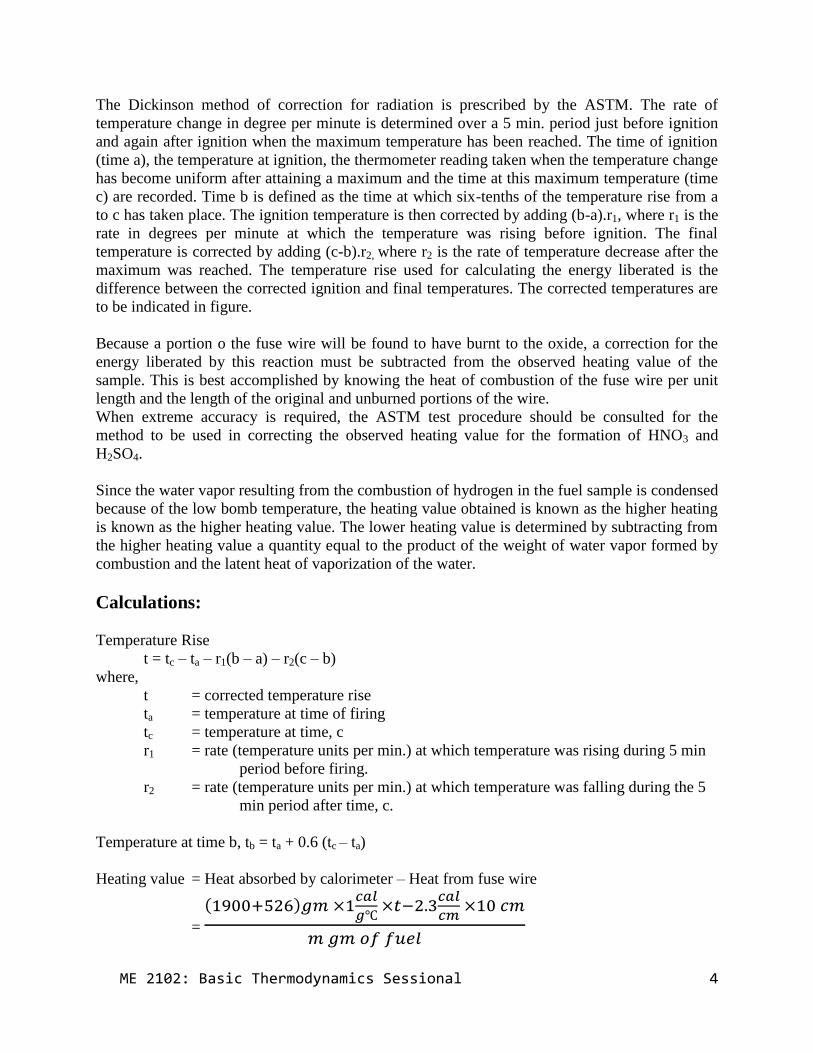
Calculations:
Temperature Rise
t = tc – ta – r1(b – a) – r2(c – b)
where,
t = corrected temperature rise
ta = temperature at time of firing
tc = temperature at time, c
r1 = rate (temperature units per min.) at which temperature was rising during 5 min
period before firing.
r2 = rate (temperature units per min.) at which temperature was falling during the 5
min period after time, c.
Temperature at time b, tb = ta + 0.6 (tc – ta)
Heating value = Heat absorbed by calorimeter – Heat from fuse wire
=
( )
ME 2102: Basic Thermodynamics Sessional 5
AHSANULLAH UNIVERSITY OF SCIENCE & TECHNOLOGY
ME 2102: Basic Thermodynamics Sessional
Experiment No.: 1
Name of the Experiment:
Determination of Heating Value of Coal by Bomb Calorimeter
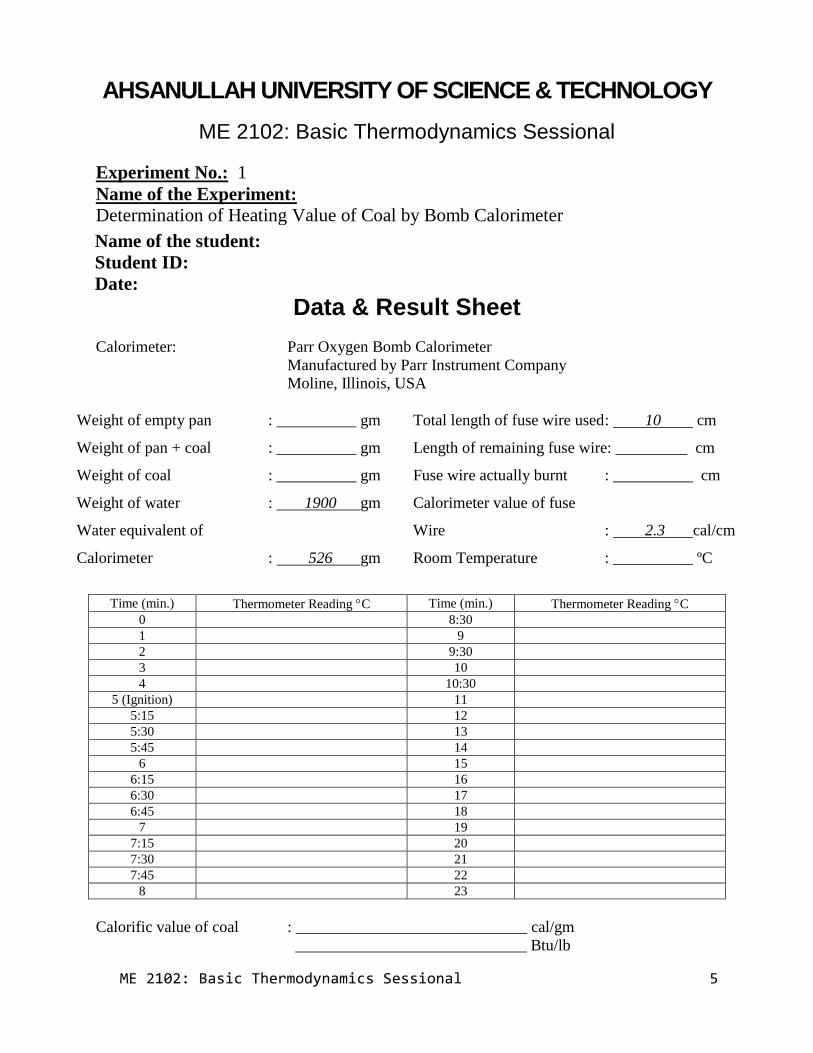
Data & Result Sheet
Calorimeter: Parr Oxygen Bomb Calorimeter
Manufactured by Parr Instrument Company
Moline, Illinois, USA
Weight of empty pan : __________ gm
Weight of pan + coal : __________ gm
Weight of coal : __________ gm
Weight of water : 1900 gm
Water equivalent of
Calorimeter : 526 gm
Total length of fuse wire used : 10 cm
Length of remaining fuse wire: _________ cm
Fuse wire actually burnt : __________ cm
Calorimeter value of fuse
Wire : 2.3 cal/cm
Room Temperature : __________ ºC
Time (min.) Thermometer Reading C Time (min.) Thermometer Reading C
0 8:30
1 9
2 9:30
3 10
4 10:30
5 (Ignition) 11
5:15 12
5:30 13
5:45 14
6 15
6:15 16
6:30 17
6:45 18
7 19
7:15 20
7:30 21
7:45 22
8 23
Calorific value of coal : _____________________________ cal/gm
_____________________________ Btu/lb
Name of the student:
Student ID:
Date:
ME 2102: Basic Thermodynamics Sessional 6
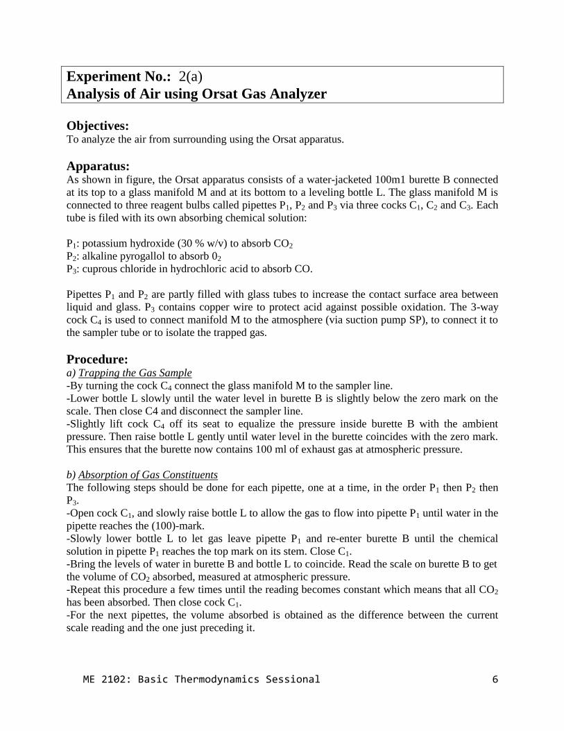
Experiment No.: 2(a)
Analysis of Air using Orsat Gas Analyzer
Objectives: To analyze the air from surrounding using the Orsat apparatus.
Apparatus: As shown in figure, the Orsat apparatus consists of a water-jacketed 100m1 burette B connected
at its top to a glass manifold M and at its bottom to a leveling bottle L. The glass manifold M is
connected to three reagent bulbs called pipettes P1, P2 and P3 via three cocks C1, C2 and C3. Each
tube is filed with its own absorbing chemical solution:
P1: potassium hydroxide (30 % w/v) to absorb CO2
P2: alkaline pyrogallol to absorb 02
P3: cuprous chloride in hydrochloric acid to absorb CO.
Pipettes P1 and P2 are partly filled with glass tubes to increase the contact surface area between
liquid and glass. P3 contains copper wire to protect acid against possible oxidation. The 3-way
cock C4 is used to connect manifold M to the atmosphere (via suction pump SP), to connect it to
the sampler tube or to isolate the trapped gas.
Procedure: a) Trapping the Gas Sample
-By turning the cock C4 connect the glass manifold M to the sampler line.
-Lower bottle L slowly until the water level in burette B is slightly below the zero mark on the
scale. Then close C4 and disconnect the sampler line.
-Slightly lift cock C4 off its seat to equalize the pressure inside burette B with the ambient
pressure. Then raise bottle L gently until water level in the burette coincides with the zero mark.
This ensures that the burette now contains 100 ml of exhaust gas at atmospheric pressure.
b) Absorption of Gas Constituents
The following steps should be done for each pipette, one at a time, in the order P1 then P2 then
P3.
-Open cock C1, and slowly raise bottle L to allow the gas to flow into pipette P1 until water in the
pipette reaches the (100)-mark.
-Slowly lower bottle L to let gas leave pipette P1 and re-enter burette B until the chemical
solution in pipette P1 reaches the top mark on its stem. Close C1.
-Bring the levels of water in burette B and bottle L to coincide. Read the scale on burette B to get
the volume of CO2 absorbed, measured at atmospheric pressure.
-Repeat this procedure a few times until the reading becomes constant which means that all CO2
has been absorbed. Then close cock C1.
-For the next pipettes, the volume absorbed is obtained as the difference between the current
scale reading and the one just preceding it.

ME 2102: Basic Thermodynamics Sessional 7
ME 2102: Basic Thermodynamics Sessional 8
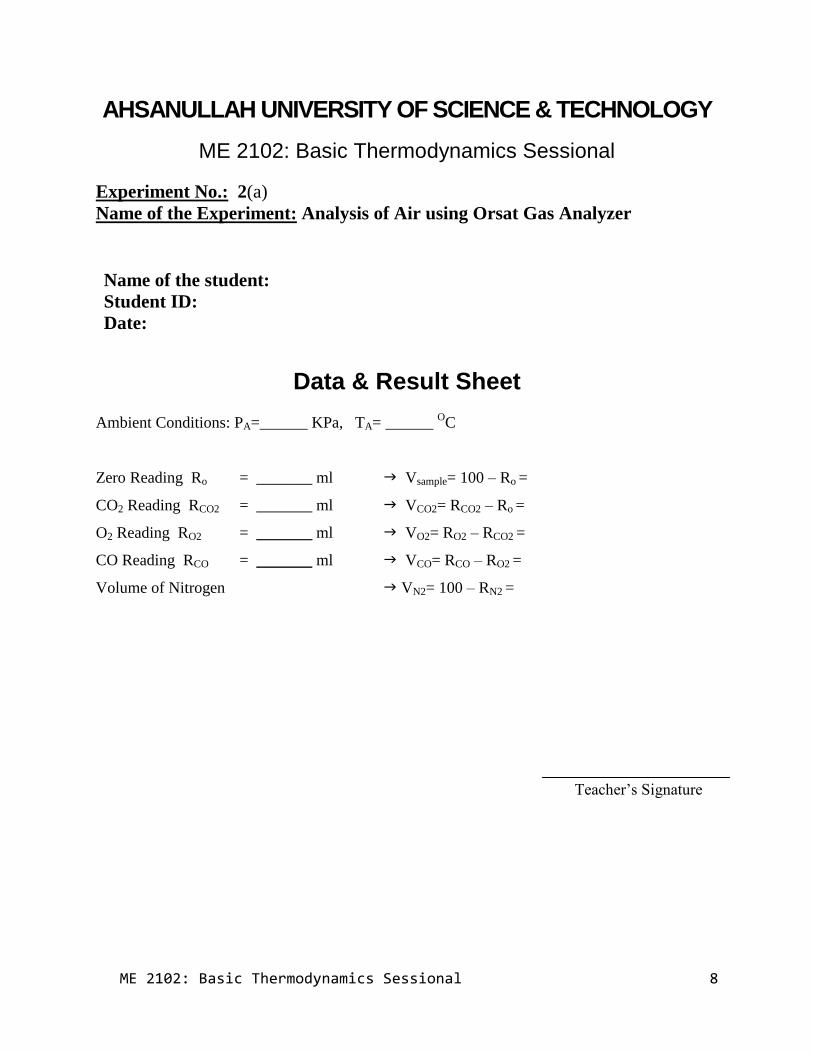
AHSANULLAH UNIVERSITY OF SCIENCE & TECHNOLOGY
ME 2102: Basic Thermodynamics Sessional
Experiment No.: 2(a)
Name of the Experiment: Analysis of Air using Orsat Gas Analyzer
Data & Result Sheet
Ambient Conditions: PA=______ KPa, TA= ______ OC
Zero Reading Ro = _______ ml Vsample= 100 – Ro =
CO2 Reading RCO2 = _______ ml VCO2= RCO2 – Ro =
O2 Reading RO2 = _______ ml VO2= RO2 – RCO2 =
CO Reading RCO = _______ ml VCO= RCO – RO2 =
Volume of Nitrogen VN2= 100 – RN2 =
Teacher’s Signature
Name of the student:
Student ID:
Date:
ME 2102: Basic Thermodynamics Sessional 12
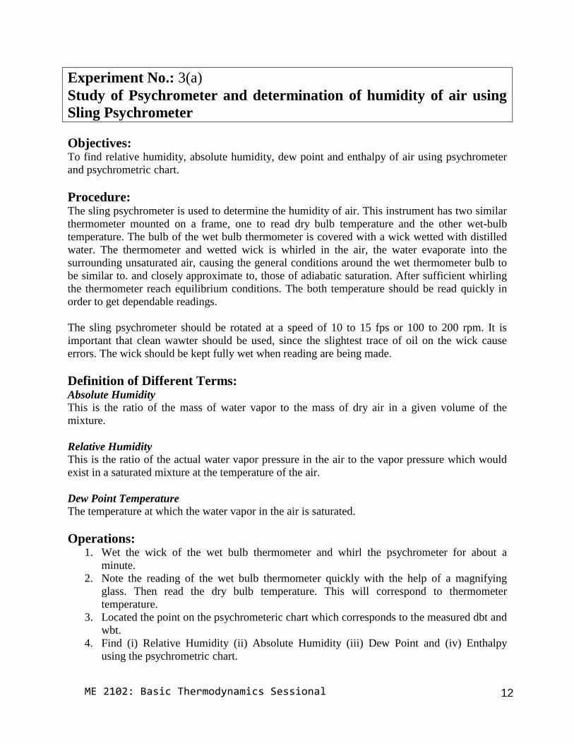
Experiment No.: 3(a)
Study of Psychrometer and determination of humidity of air using
Sling Psychrometer
Objectives:To find relative humidity, absolute humidity, dew point and enthalpy of air using psychrometer
and psychrometric chart.
Procedure:The sling psychrometer is used to determine the humidity of air. This instrument has two similar
thermometer mounted on a frame, one to read dry bulb temperature and the other wet-bulb
temperature. The bulb of the wet bulb thermometer is covered with a wick wetted with distilled
water. The thermometer and wetted wick is whirled in the air, the water evaporate into the
surrounding unsaturated air, causing the general conditions around the wet thermometer bulb to
be similar to. and closely approximate to, those of adiabatic saturation. After sufficient whirling
the thermometer reach equilibrium conditions. The both temperature should be read quickly in
order to get dependable readings.
The sling psychrometer should be rotated at a speed of 10 to 15 fps or 100 to 200 rpm. It is
important that clean wawter should be used, since the slightest trace of oil on the wick cause
errors. The wick should be kept fully wet when reading are being made.
Definition of Different Terms:Absolute Humidity
This is the ratio of the mass of water vapor to the mass of dry air in a given volume of the
mixture.
Relative Humidity
This is the ratio of the actual water vapor pressure in the air to the vapor pressure which would
exist in a saturated mixture at the temperature of the air.
Dew Point Temperature
The temperature at which the water vapor in the air is saturated.
Operations:1. Wet the wick of the wet bulb thermometer and whirl the psychrometer for about a
minute.
2. Note the reading of the wet bulb thermometer quickly with the help of a magnifying
glass. Then read the dry bulb temperature. This will correspond to thermometer
temperature.
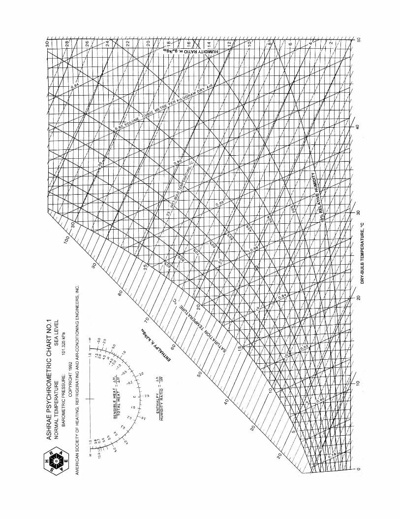
3. Located the point on the psychrometeric chart which corresponds to the measured dbt and
wbt.
4. Find (i) Relative Humidity (ii) Absolute Humidity (iii) Dew Point and (iv) Enthalpy
using the psychrometric chart.
ME 2102: Basic Thermodynamics Sessional 10
ME 2102: Basic Thermodynamics Sessional 14
AHSANULLAH UNIVERSITY OF SCIENCE & TECHNOLOGY
ME 2102: Basic Thermodynamics Sessional
Experiment No.: 3
Name of the Experiment:
Study of Psychrometer and determination of humidity of air using Sling
Psychrometer
Data Sheet
Wet Bulb Temperature : _____________ ºC
Dry Bulb Temperature : _____________ ºC
Relative Humidity : _____________ %
Absolute Humidity : _____________ kgw/kgda
Dew Point Temperature : _____________ ºC
Enthalpy : _____________ kJ/Kg
Teacher’s Signature
Name of the student:
Student ID:
Date:

Experiment 2(b)
Flash Point and Fire point of Fuel (kerosene oil)
Introduction:
Flash Point:
The flash point of a volatile material is the lowest temperature at which it can vaporize to form
an ignitable mixture in air.
Measuring a flash point requires an ignition source. At the flash point, the vapor may cease to
burn when the source of ignition is removed.
The flash point is not to be confused with the auto ignition temperature, which does not require
an ignition source, or the fire point, the temperature at which the vapor continues to burn after
being ignited. Neither the flash point nor the fire point is dependent on the temperature of the
ignition source, which is much higher.
The flash point is often used as a descriptive characteristic of liquid fuel, and it is also used to
help characterize the fire hazards of liquids. “Flash point” refers to both flammable liquids and
combustible liquids. There are various standards for defining each term. Liquids with a flash
point less than 60.5 or 37.8 °C (140.9 or 100.0 °F) — depending upon the standard being applied
— are considered flammable, while liquids with a flash point above those temperatures are
considered combustible.
Fire Point:
The fire point of a fuel is the temperature at which it will continue to burn for at least 5 seconds
after ignition by an open flame.
At the flash point, a lower temperature, a substance will ignite briefly, but vapor might not be
produced at a rate to sustain the fire. Most tables of material properties will only list material
flash points, but in general the fire points can be assumed to be about 10 °C higher than the flash
points. However, this is no substitute for testing if the fire point is safety critical. It is done by
open cup apparatus
9
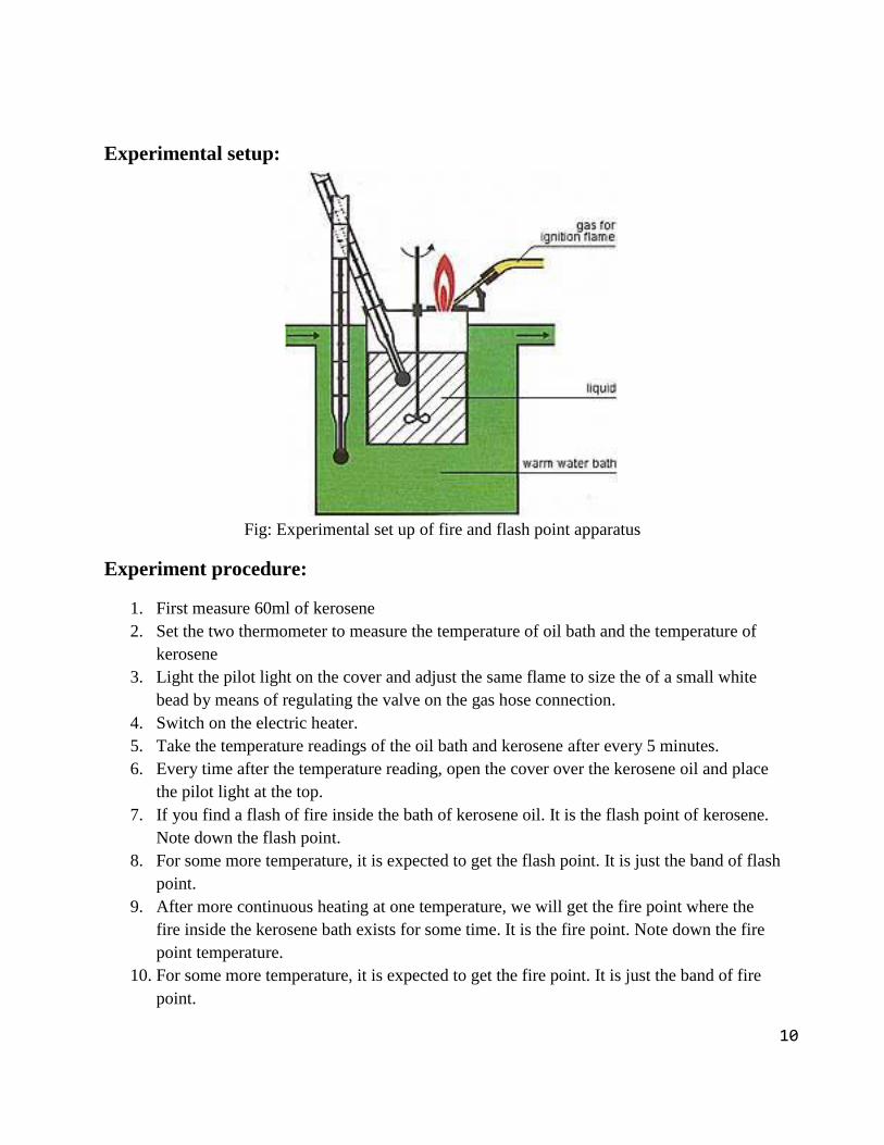
Experimental setup:
Fig: Experimental set up of fire and flash point apparatus
Experiment procedure:
1. First measure 60ml of kerosene
2. Set the two thermometer to measure the temperature of oil bath and the temperature of
kerosene
3. Light the pilot light on the cover and adjust the same flame to size the of a small white
bead by means of regulating the valve on the gas hose connection.
4. Switch on the electric heater.
5. Take the temperature readings of the oil bath and kerosene after every 5 minutes.
6. Every time after the temperature reading, open the cover over the kerosene oil and place
the pilot light at the top.
7. If you find a flash of fire inside the bath of kerosene oil. It is the flash point of kerosene.
Note down the flash point.
8. For some more temperature, it is expected to get the flash point. It is just the band of flash
point.
9. After more continuous heating at one temperature, we will get the fire point where the
fire inside the kerosene bath exists for some time. It is the fire point. Note down the fire
point temperature.
10. For some more temperature, it is expected to get the fire point. It is just the band of fire
point.
10
Result
Flash Point:
Band of Flash point:
Fire Point:
11ME 2102: Basic Thermodynamics Sessional
ME 2102: Basic Thermodynamics Sessional 18
Experiment No.: 4
Determination of Carbon Residue of Oil (Conradson Method)
Objective: To determination of carbon residue of High Speed Diesel Oil
Summary of the Conradson Method:
A weighed quantity of oil sample is placed in a crucible and subjected to destructive
distillation. The residue undergoes cracking and cooking reactions during a fixed period of
severe heating. At the end of the specified heating period the test crucible containing the
carbonaceous residue is cooled in a desiccator and weighed. The residue remaining is calculated
as a percentage of the original sample and reported as Conradson carbon residue.
Apparatus: Porcelain Crucible
Skidmore Iron Crucible
Spun Sheet Iron Crucible
Wire Support (Triangle of bare Nichrome wire)
Circular Sheet Iron Hood
Insulator (Ceramic block/ refractory ring)
Burner
Working Procedure: 1. Weigh to the nearest 10 mg sample of the oil to be tested, free of moisture and other
suspended matters into a tarred porcelain crucible containing two glass beads about 0.1 inch in
diameter. Place the crucible in the center of the skidmore crucible. Level the sand in the large
sheet iron crucible and set the skidmore crucible on it in the exact center of the iron crucible.
2. Apply cover to both the skidmore and the iron crucible, the one on the latter fitting
loosely to allow free exit to the vapors as formed.
3. On a suitable stand or, ring, place the bare Nichrome wire triangle and on it the insulator.
Next, center the sheet iron crucible in the insulator with its bottom resting on top of the triangle,
and cover the whole with the sheet iron hood in order to distribute the heat uniformly during the
process.
4. Apply heat with a high strong flame from the gas burner. So the precognition period will
be 10 1.0 min (a shorter time may start the distillation so rapidly as to cause foaming or too
high a flame). When smoke appears above the chimney, immediately move or, tilt the burner so
that the gas flame plays on the sides of the crucible for the purpose of igniting the vapors. Then
ME 2102: Basic Thermodynamics Sessional 19
remove the heat temporarily and before replacing adjust by screwing down the pinch cock on the
gas tubing so that the ignited vapors burn uniformly with the flame above the chimney but not
above the wire bridge. The period of burning the vapors shall be 10.0 to 12.0 min. If it is found
impossible to meet the requirements for both flame and burning time, the requirements for
burning time is the more important.
5. When the vapor ceases to burn and no further blue smoke can be observed, readjust the
burner and held the heat as at the sheet iron crucible a cherry red and maintain for exactly 7.0
min. The total period of heating shall be 30 2.0 min. which constitutes as additional limitation
on the tolerances for the pre-ignition and burning periods. There should be no difficulty in
carrying out the test exactly as directed with the gas burner of the type named using city gas
(about 550 Btu) with top of the burner about 2 in below the bottom of the crucible. The time
periods shall be observed with whatever burner and gas is used.
6. Remove the burner and allow the apparatus to cool until no smoke appears and then
remove the cover of the skidmore crucible (about 15.0 min). Then remove the porcelain or, silica
crucible with heated tongs, place in the desiccator, cool and weigh. Calculate the percentage of
carbon residue on the original sample.
ME 2102: Basic Thermodynamics Sessional 20
AHSANULLAH UNIVERSITY OF SCIENCE & TECHNOLOGY
ME 2102: Basic Thermodynamics Sessional
Experiment No.: 4
Name of the Experiment:
Determination of Carbon Residue of Oil (Conradson Method)
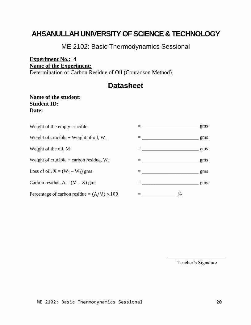
Datasheet
Weight of the empty crucible
Weight of crucible + Weight of oil, W1
Weight of the oil, M
Weight of crucible + carbon residue, W2
Loss of oil, X = (W1 – W2) gms
Carbon residue, A = (M – X) gms
Percentage of carbon residue = ( M)
= _______________________ gms
= _______________________ gms
= _______________________ gms
= _______________________ gms
= _______________________ gms
= _______________________ gms
= ______________ %
Teacher’s Signature
Name of the student:
Student ID:
Date:
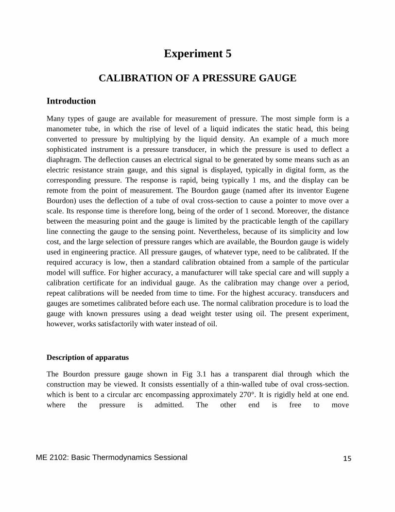
Experiment 5
CALIBRATION OF A PRESSURE GAUGE
Introduction
Many types of gauge are available for measurement of pressure. The most simple form is a
manometer tube, in which the rise of level of a liquid indicates the static head, this being
converted to pressure by multiplying by the liquid density. An example of a much more
sophisticated instrument is a pressure transducer, in which the pressure is used to deflect a
diaphragm. The deflection causes an electrical signal to be generated by some means such as an
electric resistance strain gauge, and this signal is displayed, typically in digital form, as the
corresponding pressure. The response is rapid, being typically 1 ms, and the display can be
remote from the point of measurement. The Bourdon gauge (named after its inventor Eugene
Bourdon) uses the deflection of a tube of oval cross-section to cause a pointer to move over a
scale. Its response time is therefore long, being of the order of 1 second. Moreover, the distance
between the measuring point and the gauge is limited by the practicable length of the capillary
line connecting the gauge to the sensing point. Nevertheless, because of its simplicity and low
cost, and the large selection of pressure ranges which are available, the Bourdon gauge is widely
used in engineering practice. All pressure gauges, of whatever type, need to be calibrated. If the
required accuracy is low, then a standard calibration obtained from a sample of the particular
model will suffice. For higher accuracy, a manufacturer will take special care and will supply a
calibration certificate for an individual gauge. As the calibration may change over a period,
repeat calibrations will be needed from time to time. For the highest accuracy. transducers and
gauges are sometimes calibrated before each use. The normal calibration procedure is to load the
gauge with known pressures using a dead weight tester using oil. The present experiment,
however, works satisfactorily with water instead of oil.
Description of apparatus
The Bourdon pressure gauge shown in Fig 3.1 has a transparent dial through which the
construction may be viewed. It consists essentially of a thin-walled tube of oval cross-section.
which is bent to a circular arc encompassing approximately 270°. It is rigidly held at one end.
where the pressure is admitted. The other end is free to move
15ME 2102: Basic Thermodynamics Sessional

and is sealed. When pressure is applied, the tube tends to straighten, so that the free end moves
slightly. This movement operates a mechanism which drives a pointer round the graduated dial,
the movement of the pointer being proportional to the applied pressure. The construction of the
dead weight tester is also shown in Fig 3.1. A cylindrical piston. free to move vertically in a
closely-fitting cylinder, is loaded with known weights. The space below the piston is filled with
water, and the pressure is transmitted by the water to the gauge under test through a transparent
hose. The pressure generated by the piston is easily found in terms of the total weight supported
and the cross-sectional area of the piston.
Pressure gauge calibrated in kN/m2.
Procedure
The weight of the piston. and its cross-sectional area, should be noted. To fill the cylinder, the
piston is removed, and water is poured into the cylinder until it is full to the overflow level. Any
air trapped in the tube may be cleared by tilting and gently tapping the apparatus. In point of fact,
a small amount of air left in the system will not affect the experiment, unless there is so much as
to cause the piston to bottom on the base of the cylinder. The piston is then replaced in the
cylinder and allowed to settle. A spirit level placed on the platform at the top of the piston may
be used to ensure that the cylinder stands quite vertically.
Weights are now added in convenient increments, and at each increment the pressure gauge
reading is observed. A similar set of results is then taken with decreasing weights. To guard
against the piston sticking in the cylinder, it is advisable to rotate the piston gently while the
pressure gauge is being read.
16ME 2102: Basic Thermodynamics Sessional
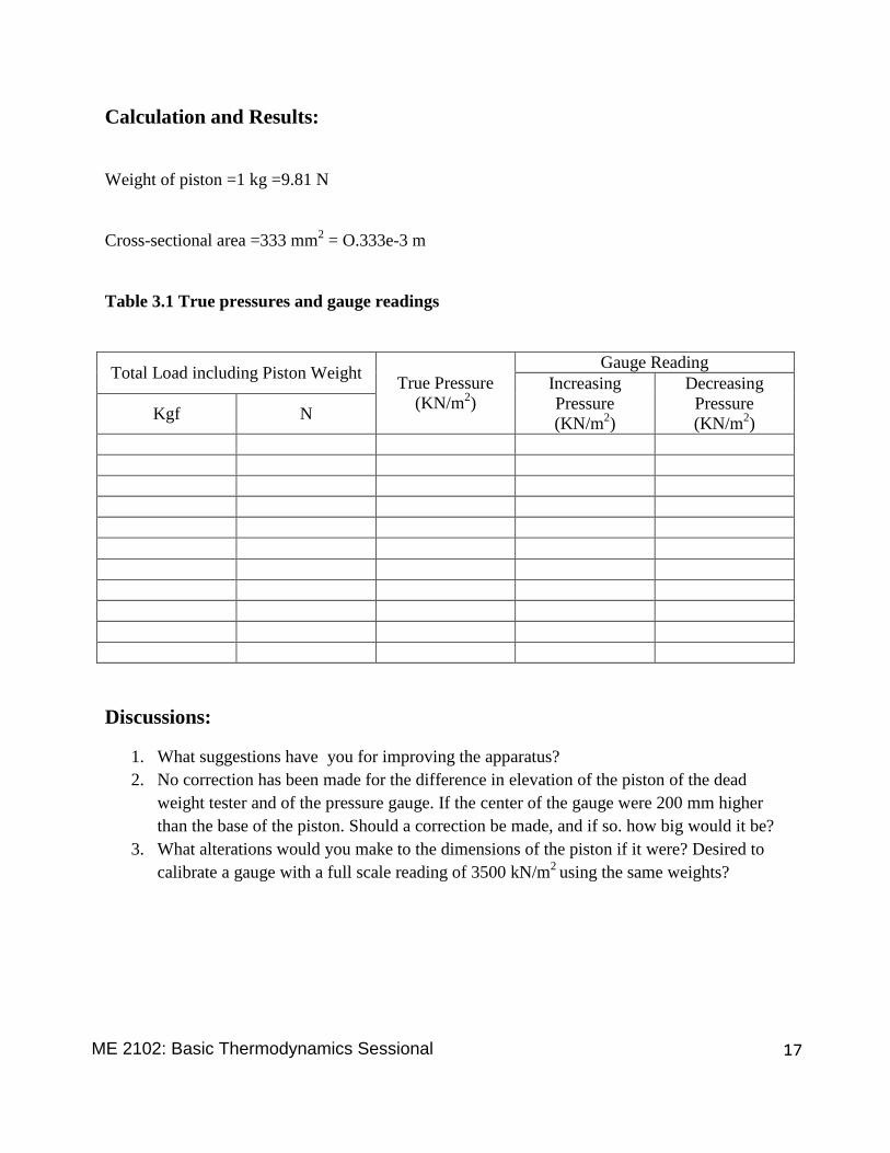
Calculation and Results:
Weight of piston =1 kg =9.81 N
Cross-sectional area =333 mm2 = O.333e-3 m
Table 3.1 True pressures and gauge readings
Total Load including Piston Weight True Pressure
(KN/m2)
Gauge Reading
Increasing
Pressure
(KN/m2)
Decreasing
Pressure
(KN/m2)
Kgf N
Discussions:
1. What suggestions have you for improving the apparatus?
2. No correction has been made for the difference in elevation of the piston of the dead
weight tester and of the pressure gauge. If the center of the gauge were 200 mm higher
than the base of the piston. Should a correction be made, and if so. how big would it be?
3. What alterations would you make to the dimensions of the piston if it were? Desired to
calibrate a gauge with a full scale reading of 3500 kN/m2
using the same weights?
17ME 2102: Basic Thermodynamics Sessional


![AHSANULLAH UNIVERSITY OF SCIENCE AND TECHNOLOGY … · CHEM 1108 [B2] [R-5B02] PHY 1106 [B1] [R-5B04] THEORY COURSE TEACHERS COURSE NO COURSE TEACHER DEPARTMENT COURSE NO COURSE TEACHER](https://img.pdfslide.us/doc/110x75/5e715f563d559f260a343999/ahsanullah-university-of-science-and-technology-chem-1108-b2-r-5b02-phy-1106.jpg)