Embed Size (px)
Citation preview

CE 412
Structural Analysis and Design Sessional-II
Department of Civil Engineering Ahsanullah University of Science and Technology
Version 1; November, 2015

AHSANULLAH UNIVERSITY OF SCIENCE &TECHNOLOGY
Page | 2
CE412: Structural Analysis & Design Sessional - II
Preface
This lab handout is intended to give an overview of a Multi storied Building and a
Balanced Cantilever Bridge structural analysis and design. It concentrates on the gravity loading
only. This handout provides a basic guideline for analysis, design and detailing works as well as
reviewing a standard code of practice. To provide the undergraduate students a well-organized,
user-friendly, and easy-to-follow resource, this handout is divided into two major parts. The first
part mainly focuses on the structural analysis and design of Reinforced concrete (RC)
Multistoried Building that includes design of Slab, Beam, Column, Stair, Water reservoir and
Lateral load analysis. The other part deals with the Balanced Cantilever Bridge including an
introduction to Bridge Engineering, details about Balanced Cantilever Bridge, design of Deck
Slab, design of Railing, Post and Curb/Sidewalk, design of Interior Girder considering dead and
live loads only, design of Exterior Girder considering dead and live loads only, design of
Diaphram or Cross Girder and Design of Articulation. Handouts of Dr. Khan Mahmud Amanat,
and Mr. Ruhul Amin, of BUET were helpful as well as suggestions from some faculty members
of the Department of Civil Engineering, AUST.
Zasiah Tafheem
Shafiqul Islam
Department of Civil Engineering
Ahsanullah University of Science and Technology

AHSANULLAH UNIVERSITY OF SCIENCE &TECHNOLOGY
Page | 3
CE412: Structural Analysis & Design Sessional - II
INDEX
Part I
Structural Analysis and Design of the Multistoried RC building
Sl. No. Name Page no.
1 Introduction 5
2 Design of Stair 10
3 Design of Overhead Water Reservoir (OWR) 14
4 Lateral Load Calculation 23
5 Design of Slab 27
6 Design of Beam only for Gravity Load 31
7 Design of Column 38
8 References 45

AHSANULLAH UNIVERSITY OF SCIENCE &TECHNOLOGY
Page | 4
CE412: Structural Analysis & Design Sessional - II
Part II:
Preliminary Design of the Superstructure of a Balanced Cantilever
Bridge for Gravity loading
Sl.
No.
Name Page No.
1 Introduction to Bridge Engineering 49
2 About Balanced Cantilever Bridge 60
3 Design of Deck Slab 69
4 Design of Railing, Post and Sidewalk 71
5 Design of Interior Girder 74
6 Design of Exterior Girder 90
7 Design of Cross Girder/ Diaphram 92
8 Design of Articulation 93
9 References 99

AHSANULLAH UNIVERSITY OF SCIENCE &TECHNOLOGY
Page | 5
CE412: Structural Analysis & Design Sessional - II
Part I:Structural Analysis and Design of the Multistoried building
Introduction
Generally the design of any structure (building, bridge etc) can be dividing in two segments,
Foundation design (footing, basement, retaining wall, abutment, underground water
reservoir etc)
Design of superstructure (beam, column, slab, girder, stair etc)
Figure 1: Super structural elements

AHSANULLAH UNIVERSITY OF SCIENCE &TECHNOLOGY
Page | 6
CE412: Structural Analysis & Design Sessional - II
Figure 2: Foundation elements
AHSANULLAH UNIVERSITY OF SCIENCE &TECHNOLOGY
Page | 7
CE412: Structural Analysis & Design Sessional - II
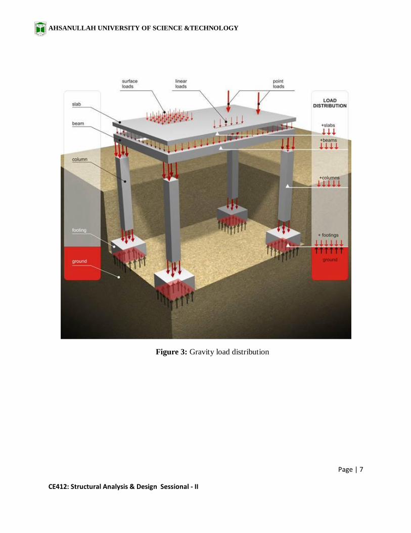
Figure 3: Gravity load distribution
AHSANULLAH UNIVERSITY OF SCIENCE &TECHNOLOGY
Page | 8
CE412: Structural Analysis & Design Sessional - II
Foundation design: it can also be dividing in two parts,
Determination of soil load bearing capacity, soil stability and the lateral forces introduce
by soil.
The structural design of the elements beneath GL.
# Note: the B.C. of soil and the other parameters like atterberg limit, angle of internal friction,
consolidation can be taken direct from soil report but a general cross check between the relations
among the parameters are required.
Steps of design
Specified the type of structural system like RCC or Steel or Composite, beam supported
or flat plate or braced etc.
Specified the loads considering the type of services like residential or commercial or
institutional etc based on associate codes and judgments.
Prepare a preliminary model of the structure with preliminary sections based on the
judgment.
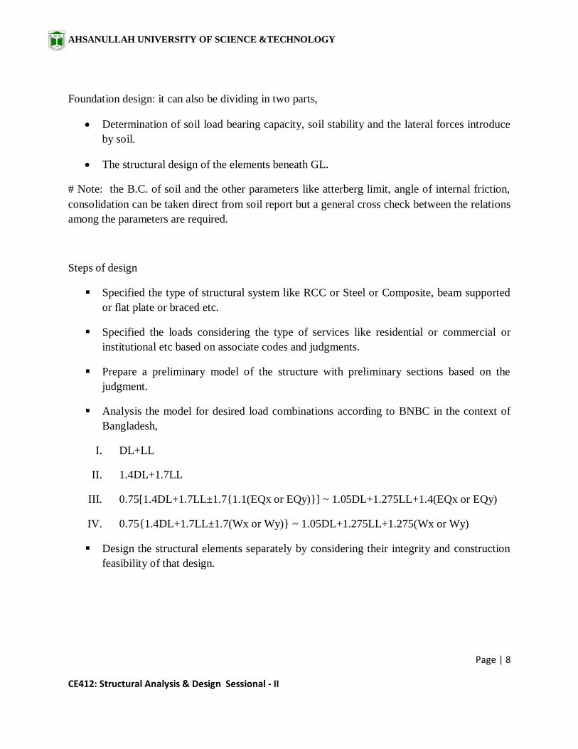
Analysis the model for desired load combinations according to BNBC in the context of
Bangladesh,
I. DL+LL
II. 1.4DL+1.7LL
III. 0.75[1.4DL+1.7LL±1.7{1.1(EQx or EQy)}] ~ 1.05DL+1.275LL+1.4(EQx or EQy)
IV. 0.75{1.4DL+1.7LL±1.7(Wx or Wy)} ~ 1.05DL+1.275LL+1.275(Wx or Wy)
Design the structural elements separately by considering their integrity and construction
feasibility of that design.

AHSANULLAH UNIVERSITY OF SCIENCE &TECHNOLOGY
Page | 9
CE412: Structural Analysis & Design Sessional - II
Design Criteria
U.S.D Method
ƒc' = Cylindrical strength of concrete
ƒy = Yield strength of reinforcement
Vc =Allowable shear force without web
reinforcement = 2 Φ b′
c wd
V = Allowable shear force with web
reinforcement = 8 Φ b′
c wd
V =Allowable peripherial shear force in slab
and footing without web reinforcement
=4 Φ b′
c wd
Strength reduction factors :
# Flexure, without axial load = 0.90
# Axial compression and axial compression
with flexure:
Members with spiral Reinforcement = 0.75
Other reinforcement = 0.70
# Shear and torsion = 0.85
# Bearing on concrete = 0.75
W.S.D Method
ƒc' = Cylindrical strength of concrete
ƒc =0.45 ƒc'
ƒy = Yield strength of reinforcement
Ec =w1.5 ×33 c'
n = Es
Er=
29x106
14515 x33 fc ′
k =n
(n+r)
j = 1- k/3
R =1
2fckj
vc =Allowable shear stress without web
reinforcement =1.1 c ′
v= Allowable shear stress without web
reinforcement =5 c ′
Vc =Allowable peripherial shear stress in
slab and footing without web reinforcement
=2 c ′
AHSANULLAH UNIVERSITY OF SCIENCE &TECHNOLOGY
Page | 10
CE412: Structural Analysis & Design Sessional - II
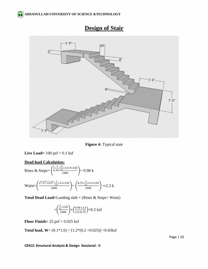
Design of Stair
Figure 4: Typical stair
Live Load= 100 psf = 0.1 ksf
Dead load Calculation:
Rises & Steps= 1
2∗
6
12∗
10
12∗3.5∗9∗150
1000 = 0.98 k
Waist= 7.52+4.52∗
6
12∗3.5∗150
1000 =
8.75∗6
12∗3.5∗150
1000 =2.3 k
Total Dead Load=Landing slab + (Rises & Steps+ Waist)
= 6
12∗150
1000 +
0.98+2.3
3.5∗8.75 =0.2 ksf
Floor Finish= 25 psf = 0.025 ksf
Total load, W= (0.1*1.6) + [1.2*(0.2 +0.025)] =0.43ksf

AHSANULLAH UNIVERSITY OF SCIENCE &TECHNOLOGY
Page | 11
CE412: Structural Analysis & Design Sessional - II
𝐌+ =𝐖𝐋𝟐
𝟏𝟒=
0.43 ∗ 2∗3.5+8.75 ²
14=7.6 k-ft/ft
𝐌− =𝐖𝐋𝟐
𝟗=
0.43 ∗15.752
9=11.85 k-ft/ft
d= (t-1) = (6-1) = 5"
fy= 60000 psi
f'c= 3000 psi
𝐩𝐦𝐚𝐱 = 𝟎.𝟖𝟓 ∗ 𝛃𝟏 ∗𝐟′𝐜
𝐟𝐲∗
𝟎.𝟎𝟎𝟑
𝟎.𝟎𝟎𝟑+ є𝐭= 0.85 ∗ 0.85 ∗
3000
60000∗
0.003
0.003 +0.004= 0.015
Mu = ф ∗ pmax ∗ fy ∗ b ∗ d2 ∗ 1 − 0.59 ∗pmax ∗ fy
f′c
d2 = 11.85∗12
0.9∗0.015∗60∗12∗ 1−0.59∗0.015∗60
3 =
142 .2
8=17.8
d = 4.21"< provided, 5" (ok)
Table 1: Minimum ratios of temperature and shrinkage reinforcement in slabs based on gross
concrete area. (Ref: ACI Code, Design of Concrete Structure, 13th edition, Chap-13, P-417)
𝐀𝐬𝐦𝐢𝐧 = 𝟎.𝟎𝟎𝟏𝟖 ∗ 𝐛 ∗ 𝐭 = 0.0018 ∗ 12 ∗ 6 = 0.129in.2
+𝐀𝐬 = 𝐌∗𝟏𝟐
ф∗𝐟𝐲∗ 𝐝−𝐚
𝟐
= 7.6∗12
0.9∗60∗ 5−0.7
2 = 0.37in.2(controlled)
𝐚 = 𝐀𝐬∗𝐟𝐲
.𝟖𝟓∗𝐟′𝐜∗𝐛=
0.37∗60
.85∗3∗12= 0.7(ok)
Now,0.16∗12
0.37= 5.2"; use Ø12mm@5" c/c alt ckd
Again,

AHSANULLAH UNIVERSITY OF SCIENCE &TECHNOLOGY
Page | 12
CE412: Structural Analysis & Design Sessional - II
−𝐀𝐬 = 𝐌∗𝟏𝟐
ф∗𝐟𝐲∗ 𝐝−𝐚
𝟐
= 11.85∗12
0.9∗60∗ 5− 1
2 =0.58in.2(controlled)
𝐚 = 𝐀𝐬∗𝐟𝐲
.𝟖𝟓∗𝐟′𝐜∗𝐛=
0.5∗60
.85∗3∗12= 1.1(ok)
The distance between two cranked rod is 10".
So, Required reinforcement = 0.58- 0.16∗12
10=0.39in.2
The extra negative reinforcement required, 0.39
0.16*
10
12= 2. So, use 2-Ø12mmas extra top.
For shrinkage, Asmin = 0.0018 ∗ 12 ∗ 6 = 0.129in.2
Now, 0.121∗12
0.129= 11.23"; useØ10mm@10" c/c
Stair Beam
Assume beam size, 10"x12"
d= (t-1) = (12-2.5) = 9.5"
So, self weight = .83*1*150= 0.12k/ft
Load on Stair beam = 0.5∗ 15.75∗3.5∗0.2 ∗2 +0.5∗ 15.75∗3.5∗0.1 ∗2
8 + 0.42*10*0.12 + 0.12 = 2.7 k/ft
𝐌+ =𝐖𝐋𝟐
𝟏𝟒=
2.7 ∗8²
14=12.3 k-ft
𝐌− =𝐖𝐋𝟐
𝟏𝟔=
2.7 ∗82
16=10.8 k-ft
𝐩𝐦𝐚𝐱 = 𝟎.𝟖𝟓 ∗ 𝛃𝟏 ∗𝐟′𝐜
𝐟𝐲∗
𝟎.𝟎𝟎𝟑
𝟎.𝟎𝟎𝟑+ є𝐭= 0.85 ∗ 0.85 ∗
3000
60000∗
0.003
0.003 +0.004= 0.015
Mu = ф ∗ pmax ∗ fy ∗ b ∗ d2 ∗ 1 − 0.59 ∗pmax ∗ fy
f′c
d2 = 12.3∗12
0.9∗0.015∗60∗12∗ 1−0.59∗0.015∗60
3 = 18.45
d = 4.3" < provided, 5" (ok)
Asmin= 𝟐𝟎𝟎
𝐟𝐲bd = 0.32 in
2
+𝐀𝐬 = 𝐌∗𝟏𝟐
ф∗𝐟𝐲∗ 𝐝−𝐚
𝟐
= 12.3∗12
0.9∗60∗ 9.5−0.7
2 = 0.3 in.2

AHSANULLAH UNIVERSITY OF SCIENCE &TECHNOLOGY
Page | 13
CE412: Structural Analysis & Design Sessional - II
𝐚 = 𝐀𝐬∗𝐟𝐲
.𝟖𝟓∗𝐟′𝐜∗𝐛=
0.3∗60
.85∗3∗12= 0.7(ok)
So, use 2-Ø16mm st at top and bottom.
Figure 5: Reinforcement Details of stair.
AHSANULLAH UNIVERSITY OF SCIENCE &TECHNOLOGY
Page | 14
CE412: Structural Analysis & Design Sessional - II
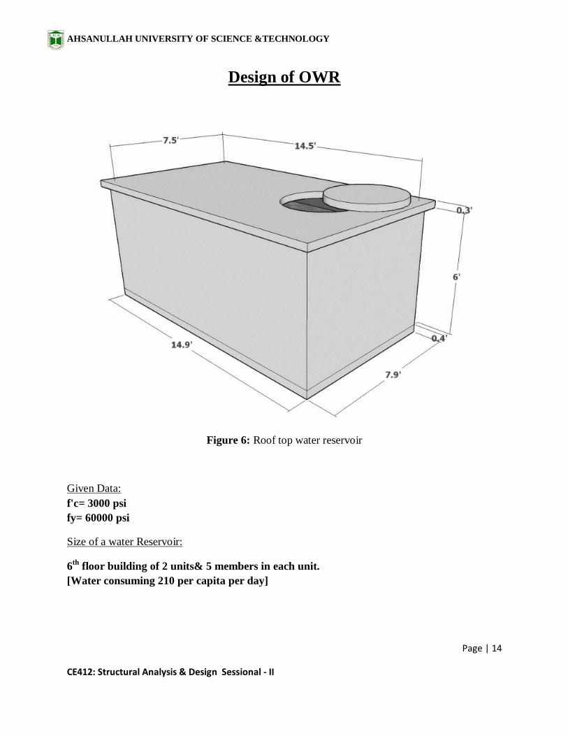
Design of OWR
Figure 6: Roof top water reservoir
Given Data:
f'c= 3000 psi
fy= 60000 psi
Size of a water Reservoir:
6th
floor building of 2 units& 5 members in each unit.
[Water consuming 210 per capita per day]

AHSANULLAH UNIVERSITY OF SCIENCE &TECHNOLOGY
Page | 15
CE412: Structural Analysis & Design Sessional - II
Total members= 6*2*5= 60 persons.
Total water consuming= 60*210= 12600 litters for a full day.
= 12600
1000m3= 12.6*3.283 = 445ft3
Inner length & width of Reservoir is,
Length=14.5 ft
width=7.5 ft
so, Height=445
7.5∗14.5=4.09 ft+1 ft=5.09 ft~ 6 ft ; [where, free Board= 1 ft]
Height= 6 ft
Figure 7: Pressure distribution on reservoir wall
For Vertical Reinforcement:
Let wall thickness = 5"
so, Effective depth, d= 5-1 = 4"
𝐩𝐦𝐚𝐱 = 𝟎.𝟖𝟓 ∗ 𝛃𝟏 ∗𝐟′𝐜
𝐟𝐲∗
𝟎.𝟎𝟎𝟑
𝟎.𝟎𝟎𝟑+є𝐭= 0.85 ∗ 0.85 ∗
3000
60000∗
0.003
0.003+0.004= 0.015
Mu = ф ∗ pmax ∗ fy ∗ b ∗ d2 ∗ 1 − 0.59 ∗pmax ∗ fy
f′c
d2 = 2.25∗12
0.9∗0.015∗60∗12∗ 1−0.59∗0.015∗60
3 =
27
8=3.8

AHSANULLAH UNIVERSITY OF SCIENCE &TECHNOLOGY
Page | 16
CE412: Structural Analysis & Design Sessional - II
d = 1.84"< provided, 4" (ok)
𝐀𝐬𝐦𝐢𝐧 = 𝟎.𝟎𝟎𝟏𝟖 ∗ 𝐛 ∗ 𝐭 = 0.0018 ∗ 12 ∗ 5 = 0.12 in2/ft
[Let, a=0.25]
𝐀𝐬 = 𝐌∗𝟏𝟐
ф∗𝐟𝐲∗ 𝐝−𝐚
𝟐
=2.25∗12
.90∗50∗ 4−.25
2
= 0.13 in2/ft(controlled)
𝐚 = 𝐀𝐬∗𝐟𝐲
.𝟖𝟓∗𝐟′ 𝐜∗𝐛=
0.13∗60
.85∗3∗12= 0.26(ok)
use, ф10mm@8in c/c.
For Horizontal Reinforcement:
𝐅𝐨𝐫𝐜𝐞 = 𝛄 ∗ 𝐡 ∗(𝟏𝟒.𝟓
𝟐+
𝟏𝟒.𝟓
𝟐) = 62.5 * 6* (
14.5
2+
14.5
2) = 5438 lb
Again,
force
stress=
5438
fy =
5438
60000 =0.09 in2/ft
Use ф10 @ 8in c/c
Slab Load Distribution:
Bottom slab:
Table 2: Minimum thickness of nonprestressed one-way slabs. (Ref: ACI Code, Design of
Concrete Structure, 13th edition, Chap-13, P-416)
Thickness=7.5
20∗ 12 = 4.5 in

AHSANULLAH UNIVERSITY OF SCIENCE &TECHNOLOGY
Page | 17
CE412: Structural Analysis & Design Sessional - II
Self weight of slab =𝟏.𝟐 ∗1∗
4.5
12∗150
1000 = 0.067ksf
5wA lA4
384 EI=
5wB lB4
384 EI
wA lA4 = wB lB
4
wA = wB lB
lA
4
Wa =16* Wb
Wa +Wb = 0.067 ksf
Wb = .004k/ft
Wa = .064k/ft
Floor Finish= 25 psf = 0.025 ksf
Total load, W= (0.0625*1.6) + [1.2*(0.064 +0.025)] =0.21ksf
Moment for short Direction
𝐌+ =𝐖𝐋𝟐
𝟏𝟒=
0.21∗7.5²
14= 0.84 k-ft/ft
𝐌− =𝐖𝐋𝟐
𝟐𝟒=
0.21∗7.52
9= 0.5 k-ft/ft
𝐩𝐦𝐚𝐱 = 𝟎.𝟖𝟓 ∗ 𝛃𝟏 ∗𝐟′𝐜
𝐟𝐲∗
𝟎.𝟎𝟎𝟑
𝟎.𝟎𝟎𝟑+ є𝐭= 0.85 ∗ 0.85 ∗
3000
60000∗
0.003
0.003 +0.004= 0.015
Mu = ф ∗ pmax ∗ fy ∗ b ∗ d2 ∗ 1 − 0.59 ∗pmax ∗ fy
f′c
d2 = 0.84∗12
0.9∗0.015∗60∗12∗ 1−0.59∗0.015∗60
3 =
10
8=1.25
d = 1.11" < provided, 3.5" (ok)
𝐀𝐬𝐦𝐢𝐧 = 𝟎.𝟎𝟎𝟐 ∗ 𝐛 ∗ 𝐭 = 0.002 ∗ 12 ∗ 4.5 = 0.11in2/ft
AHSANULLAH UNIVERSITY OF SCIENCE &TECHNOLOGY
Page | 18
CE412: Structural Analysis & Design Sessional - II
+𝐀𝐬 = 𝐌∗𝟏𝟐
ф∗𝐟𝐲∗ 𝐝−𝐚
𝟐
= 0.84∗12
0.9∗60∗ 3.5−0.1
2 = 0.05in.2
𝐚 = 𝐀𝐬∗𝐟𝐲
.𝟖𝟓∗𝐟′ 𝐜∗𝐛=
0.05∗60
.85∗3∗12= 0.1(ok)
So, all the reinforcement will be controlled by Asmin.
Use ф10mm @ 8 in c/c ckd and 1-ф10mm as extratop.
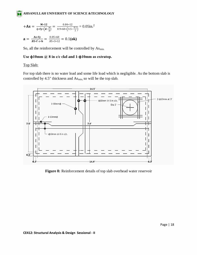
Top Slab:
For top slab there is no water load and some life load which is negligible. As the bottom slab is
controlled by 4.5" thickness and Asmin, so will be the top slab.
Figure 8: Reinforcement details of top slab overhead water reservoir

AHSANULLAH UNIVERSITY OF SCIENCE &TECHNOLOGY
Page | 19
CE412: Structural Analysis & Design Sessional - II
Beam Design:
Here, Load from Bottom Slab= 0.21ksf
Beam Thickness, t=12 in
Effective Depth, d=(12-2.5)=9.5 in
Self weight = .83*1*150= 0.12k/ft
Figure 9: Load distribution of slab
Moment for
Triangular portion=
1
2∗ 7.5∗3.5 ∗0.21
7.5+ 0.12 + .42 ∗ 6 ∗ 0.15 = 0.86k/ft
Trapezoidal portion=
1
2∗ 14.5+7.5 ∗3.75∗0.21
14.5+ 0.12 + .42 ∗ 6 ∗ 0.15 =1.1k/ft
AHSANULLAH UNIVERSITY OF SCIENCE &TECHNOLOGY
Page | 20
CE412: Structural Analysis & Design Sessional - II
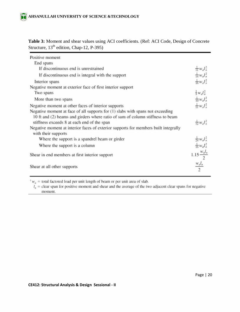
Table 3: Moment and shear values using ACI coefficients. (Ref: ACI Code, Design of Concrete
Structure, 13th edition, Chap-12, P-395)

AHSANULLAH UNIVERSITY OF SCIENCE &TECHNOLOGY
Page | 21
CE412: Structural Analysis & Design Sessional - II
Figure 10: Moment coefficients for beam.
𝐌+ =𝐖𝐋𝟐
𝟏𝟒=
1.1∗14.5²
14=16.5 k-ft
𝐌− =𝐖𝐋𝟐
𝟏𝟔=
1.1∗14.5²
16=14.5 k-ft
Mu = ф ∗ pmax ∗ fy ∗ b ∗ d2 ∗ 1 − 0.59 ∗pmax ∗ fy
f′c
𝐝𝐫𝐞𝐪𝐮𝐢𝐫𝐞𝐝=1.44in< 9.5 in Provided. (Ok)
+As = M∗12
ф∗fy∗ d−a
2
=16.5∗12
0.9∗60∗ d−1
2
= 0.41in2
Where, a = As∗fy
.85∗f′c ∗b=0.95in (Ok)
Now, Asmin=200
fy∗ bd =
200∗10∗9.5
60000= 0.32 in
2(Ok)
Use 2-ф16mmst at top and bottom.

AHSANULLAH UNIVERSITY OF SCIENCE &TECHNOLOGY
Page | 22
CE412: Structural Analysis & Design Sessional - II
Figure 11: Reinforcement details of roof top water reservoir beam

AHSANULLAH UNIVERSITY OF SCIENCE &TECHNOLOGY
Page | 23
CE412: Structural Analysis & Design Sessional - II
Figure 12: Reinforcement details of roof top water reservoir
Lateral Load Calculation
Earthquake Load Calculation:
Here,
Seismic Zone-coefficient, Z=0.15 [Dhaka]
Structural Importance Coefficient, I=1
[Residential]
Response Modification Coefficient, R=9
Now, Numerical Co-efficient, C=1.25∗S
T23
= 2.21
Figure 13: Plan of the building
47.875 ft
40.575 ft
AHSANULLAH UNIVERSITY OF SCIENCE &TECHNOLOGY
Page | 24
CE412: Structural Analysis & Design Sessional - II
s2=1.2
T=Ct*(hn)3/4
=0.073*(50
3.28)
3/4=0.565˂0.75;
∴ C =1.25 ∗ 12
(0.56)23
= 2.21
W= DL* Area* Storied= 175*47.875*40.575*5*1
1000=1699.7 k~1700 k
V =Z ∗ I ∗ C ∗ W
R=
0.15 ∗ 1 ∗ 2.21 ∗ 1700
9= 62.6 kip
Wi= DL*Area*1
1000= 175*47.875*40.575*
1
1000= = 339.9 k~ 440 k
ΣWi ∗ hi= 440*(10+20+30+40+50) =60000
Here, Ft=0 as, T<0.75
Load on each floor, Fx= V−Ft ∗W i∗hx
ΣW i∗h i
Fx=(62.6−0)∗440∗hx
60000= 0.417 ∗ hx
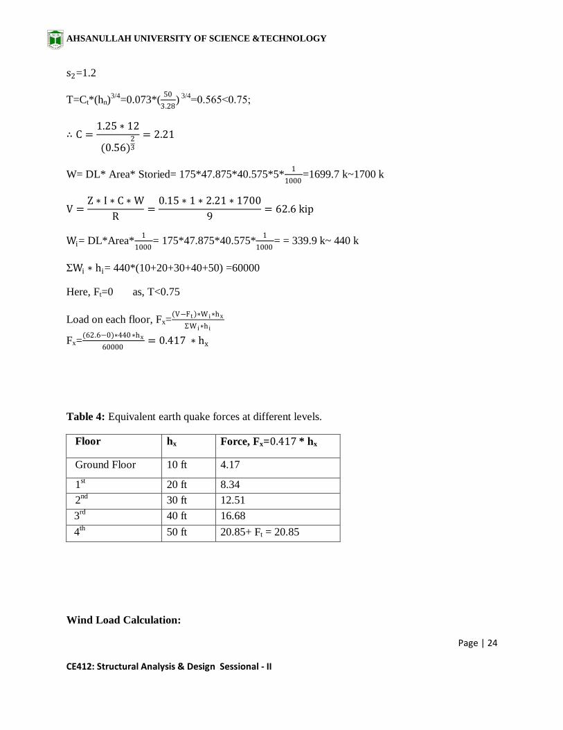
Table 4: Equivalent earth quake forces at different levels.
Floor hx Force, Fx=0.417 * hx
Ground Floor 10 ft 4.17
1st 20 ft 8.34
2nd
30 ft 12.51
3rd
40 ft 16.68
4th
50 ft 20.85+ Ft = 20.85
Wind Load Calculation:

AHSANULLAH UNIVERSITY OF SCIENCE &TECHNOLOGY
Page | 25
CE412: Structural Analysis & Design Sessional - II
(a) (b)
Figure 14: a) Plan b) Elevation of the building
Here,
Gust Co-efficient, CG = 1.43
Cc = 47.2 ∗ 10−6
B= 46.43’
L= 39.88’
Heght, h= 50’
Now,
Important Co − efficient, CI = 1.00; for Office Building.
Combined height & 𝑒𝑥𝑝𝑜𝑠𝑢𝑟𝑒 𝐶𝑜 − 𝑒𝑓𝑓𝑖𝑐𝑖𝑒𝑛𝑡, Cz = Table 6.2.15
Wind Velocity= 210 km
hr (Dhaka)
qz = CC ∗ CI ∗ Cz ∗ Vb2= 2.08 ∗ Cz
Table 5: Overall pressure coefficients, Cp for rectangular building with flat roof. (Ref: BNBC
1993)
B= 47.875
ft
40.575 ft
5@10’= 50 ft

AHSANULLAH UNIVERSITY OF SCIENCE &TECHNOLOGY
Page | 26
CE412: Structural Analysis & Design Sessional - II
Here,
L
B= 0.85;
h
B= 1.04;
∴ Cp = 1.49
Pz = CG ∗ Cp ∗ qz = 4.43 *Cz
Table 6: Equivalent wind forces at different floor levels.
Height (m) Cz qz pz = (
kn
m2)
Fz = Pz *A (KN) Fz (KN) F (K)
3.048 0.368 0.76544 1.63 1.63*3.0478*4.33 21.51 1.80
6.096 0.415 0.8632 1.84 1.84*3.0478*4.33 24.28 5.42
9.144 0.498 1.03584 2.21 2.21*3.0478*4.33 29.17 6.51
12.192 0.57 1.1856 2.53 2.53*3.0478*4.33 33.39 7.45
15.24 0.63 1.3104 2.79 2.79*3.0478
2*4.33 18.41 4.109
Design of Slab

AHSANULLAH UNIVERSITY OF SCIENCE &TECHNOLOGY
Page | 27
CE412: Structural Analysis & Design Sessional - II
Figure 15: Typical floor plan
Thickness, t = 𝑙𝑜𝑛𝑔 𝑙𝑒𝑛𝑔𝑡 (0.8+
𝑓𝑦
200000 )
36+9𝛽
Considering the largest two panels of 22'-10"x13'-2" and 22'-10"x11'-6". As the longest
dimension among both of them are same the thickness will depend on β.
So, β = 22.83
13.17= 1.73
Thickness, t =5.63 in. 5.5 in.
Load:
AHSANULLAH UNIVERSITY OF SCIENCE &TECHNOLOGY
Page | 28
CE412: Structural Analysis & Design Sessional - II
Self weight of slab =
Floor finish= 30 psf
Partition wall= 40 psf
Live Load = 40 psf
Total, W = (174+64) = 231psf
f’c=3000 psi
fy= 60000 psi
m = = 0.58 ~ 0.6 and case 4
m = = 0.5and case 9
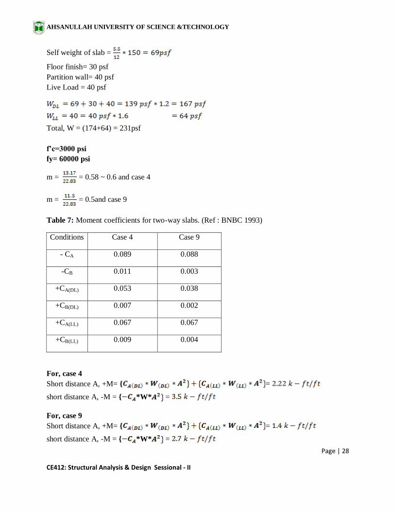
Table 7: Moment coefficients for two-way slabs. (Ref : BNBC 1993)
Conditions Case 4 Case 9
- CA 0.089 0.088
-CB 0.011 0.003
+CA(DL) 0.053 0.038
+CB(DL) 0.007 0.002
+CA(LL) 0.067 0.067
+CB(LL) 0.009 0.004
For, case 4
Short distance A, +M= { =
short distance A, -M = { *W* =
For, case 9
Short distance A, +M= { =
short distance A, -M = { *W* =

AHSANULLAH UNIVERSITY OF SCIENCE &TECHNOLOGY
Page | 29
CE412: Structural Analysis & Design Sessional - II
So, in short direction –M = and +M=
= 0.132
= 0.11
(ok)
Now, lt ckd
Again,
= 0.18 (controlled)
(ok)
The distance between two cranked rod is 16".
So, Required reinforcement = 0.18 - =0.09
The extra negative reinforcement required, * =1. So use 1- as extra top.
By observing the moment coefficients it can be said that, all the reinforcement in long direction
will be controlled by Asmin.
So, the reinforcement will be lt ckd and 1- as extra top.

AHSANULLAH UNIVERSITY OF SCIENCE &TECHNOLOGY
Page | 30
CE412: Structural Analysis & Design Sessional - II
Figure 16: Reinforcement Details of Slab

AHSANULLAH UNIVERSITY OF SCIENCE &TECHNOLOGY
Page | 31
CE412: Structural Analysis & Design Sessional - II
Design of Beam Only for Gravity Load
Figure 17: Beam layout
Load on slab, W = 231psf
and,
f’c=3000 psi
fy= 60000 psi
= = 0.016
1
3
1
2
4
1
E C A

AHSANULLAH UNIVERSITY OF SCIENCE &TECHNOLOGY
Page | 32
CE412: Structural Analysis & Design Sessional - II
=
Beam in-between A and B grid on grid 2
Trapezoidal panel:
= = *(22.92 +11.42)*5.75 = 98.73
= = *(18.29 +4.08)*7.105 = 79.4
Load on bam:
Let, Depth, h = 18''
Self weight= * = 0.187 kip/ft *1.2 = 0.22 kip/ft
Load from Slab = + = 1+1 = 2 kip/ft
Partition wall on beam = 0.42* 9* 120 = 0.45 * 1.2= 0.54 k/ft
Total load = 0.022 + 2 +0.54 = 2.57 kip/ft
AHSANULLAH UNIVERSITY OF SCIENCE &TECHNOLOGY
Page | 33
CE412: Structural Analysis & Design Sessional - II
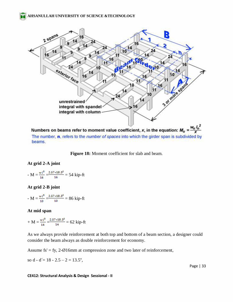
Figure 18: Moment coefficient for slab and beam.
At grid 2-A joint
- M = = = 54 kip-ft
At grid 2-B joint
- M = = = 86 kip-ft
At mid span
+ M = = = 62 kip-ft
As we always provide reinforcement at both top and bottom of a beam section, a designer could
consider the beam always as double reinforcement for economy.
Assume fs' = fy, 2-Ø16mm at compression zone and two later of reinforcement,
so d - d´= 18 - 2.5 – 2 = 13.5'',

AHSANULLAH UNIVERSITY OF SCIENCE &TECHNOLOGY
Page | 34
CE412: Structural Analysis & Design Sessional - II
ØMn = ØAs' fs' (d - d') = 0.9*(2*0.31)*60*(13.5-2.5)/12 = 31 k-ft
So Mu(concrete) = 86 – 31 = 55 k-ft
=
d = 9.6'' < 13.5" (Ok)
-As(at 2-B joint) = = 1 in²
a = 2.4 (ok)
ƿmin = 200/fy = .003
ƿ = = = 0.012> ƿmin and < 0.016 (ƿmax). So ok
Use 2-Ø20mm or 1-Ø20mm and 2-Ø16mm as extra top.
-As(at 2-A joint) = = 0.4 in²
a = 1 (ok)
Use 1-Ø20mm as extra top.
At mid span
Assuming stress block depth (a) equal to flange thickness hf and two layer of reinforcement.
d = 18-2.5-2=13.5".
+As = = 0.64 in²
a = 1.5 < 5.5, so rectangular beam.
+As = = 0.55 in²
a = 1.2 (ok)
use 2-Ø16mm as extra bottom.

AHSANULLAH UNIVERSITY OF SCIENCE &TECHNOLOGY
Page | 35
CE412: Structural Analysis & Design Sessional - II
If it was a T beam then,
Effective flange width
i) One fourth of the beam span = = 5.73' ~ 69"
ii) Stem width plus 8 times the slab thickness on both side = bw + (8*2)hf = 10" + 16*5.5" = 98"
iii) Steam width plus a flange overhang not greater than half of the clear distance to the next
beam = 10" + + = 155"
so, effective flange width, b = 69".
Asf =
ØMn1 = Ø*Asf*fy*(d - hf/2)
ØMn2 = Mu - ØMn1
As - Asf = ; a =
As = Asf + (As – Asf)
N.A. c = > hf (T beam checked)
Shear Design:
Vu =0 .5WL=18.3k
Ф*Va = 2*Ф b*d = 2*0.85 10*19.5 = 18.16 kip
Use Ø10mm as shear reinforcement.
Smax = = = 29 in
Smax = = = 6.5 in (Govern)
Smax = 24"
S = = = 833 in

AHSANULLAH UNIVERSITY OF SCIENCE &TECHNOLOGY
Page | 36
CE412: Structural Analysis & Design Sessional - II
So provide Ø10mm @ 6.5" c/c although the beam.
Beam in-between B and D grid on grid 2
Load on bam:
For UDL,
Depth, h = 18'', as it is the continuation of previous beam.
Self weight= * = 0.187 kip/ft *1.2 = 0.22 kip/ft
Load from Slab = + = 1 + 3.38 = 4.38 kip/ft
Partition wall on beam = 0.42* 9* 120 = 0.45 * 1.2= 0.54 k/ft
Total load = 0.022 + 4.38 +0.54 = 4.94 kip/ft
At grid 2-B and 2-D joint
- M = = = 38 kip-ft
At mid span
+ M = = = 26 kip-ft
For point load
= = *11.5*5.75 = 33.06
Point load from Slab = = 3.8 kip

AHSANULLAH UNIVERSITY OF SCIENCE &TECHNOLOGY
Page | 37
CE412: Structural Analysis & Design Sessional - II
M = = = 4.4 kip-ft
So finally
- M =38 + 4.4= 42.4 kip-ft
+ M= 26 + 4.4= 30.4kip-ft
By observing the values of
moment the negative moments at
supports will be controlled by the
continuation of adjacent beam. For
positive moment no extra
reinforcement other than the
continues reinforcement bars.
Figure 19: Moment co-efficient for single span beam
Figure 20: Reinforcement detail of beam
AHSANULLAH UNIVERSITY OF SCIENCE &TECHNOLOGY
Page | 38
CE412: Structural Analysis & Design Sessional - II
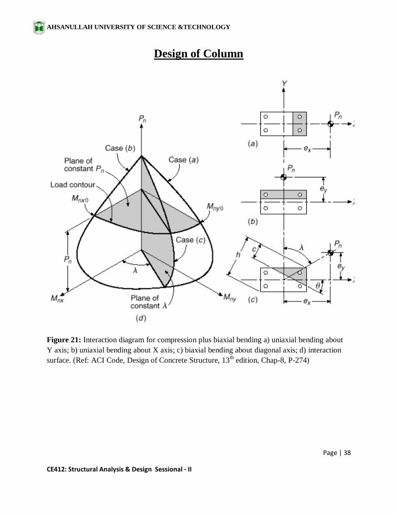
Design of Column
Figure 21: Interaction diagram for compression plus biaxial bending a) uniaxial bending about
Y axis; b) uniaxial bending about X axis; c) biaxial bending about diagonal axis; d) interaction
surface. (Ref: ACI Code, Design of Concrete Structure, 13th
edition, Chap-8, P-274)

AHSANULLAH UNIVERSITY OF SCIENCE &TECHNOLOGY
Page | 39
CE412: Structural Analysis & Design Sessional - II
Figure 22: Interaction diagram for nominal column strength in combined bending and axial load.
(Ref: ACI Code, Design of Concrete Structure, 13th edition, Chap-8, P-260)
Considering,
fy= 60000 psi
f'c=4000 psi
For a column,
P = 554 K
Mx = 85 K-ft
My = 120K-ft
For, tied column, due to accidental eccentricity strength reduction factor α = 0.8 and

AHSANULLAH UNIVERSITY OF SCIENCE &TECHNOLOGY
Page | 40
CE412: Structural Analysis & Design Sessional - II
Based on importance strength reduction factor ɸ = 0.65, (ACI Code, Design of Concrete
Structure, 13th edition, Chap-8, P-252)
let, ρg = 2%
Now, ɸPn = αɸ[0.85 f’c*Ag + ρg *Ag*fy]
554 = 0.65*0.8[0.85*4*Ag+0.02*Ag*60]
Ag = 232 in2
Let, 18"x15"
For My or dimension parallal to X axis,
ɤ = dx/Dx = (18-2.5*2)/18 = 0.72~ 0.7
Eccentricity ex = My/p = 120/554 = 0.21' = 2.6"
ex/h = 2.6/18 = 0.14
From graph, Kɳ = 0.79
Py = 853 k
For My or dimension parallal to X axis,
ɤ = dy/Dy = 0.67 0.6
ey = 85/554 = 0.15' = 1.8"
ey/h = 1.8/15 = 0.12
From graph, Kɳ = 0.85
Px = 918
For Po,Kɳ = (1.1+1.12)/2 = 1.11

AHSANULLAH UNIVERSITY OF SCIENCE &TECHNOLOGY
Page | 41
CE412: Structural Analysis & Design Sessional - II
Po = 1200
+ -
= +
ɸ Pn = 0.65*700 k =455k < 554 k (not ok)
As the difference between capacity and load is 20% so, size increment will be required. But
neglecting it continue the design.
So, column size 18"x15"and As = 0.02*18*15 = 5.4 in2. Use 12- .
Figure 23: Minimum spacing between reinforcement bars

AHSANULLAH UNIVERSITY OF SCIENCE &TECHNOLOGY
Page | 42
CE412: Structural Analysis & Design Sessional - II
The distance between reinforcement bars must be such to allow the largest expected concrete
size gravel to pass between them. In order to have properly anchored reinforcement, it is
mandatory for rebars to be surrounded by concrete.
The minimum spacing between two reinforcement bars should be at least equal to the maximum
coarse aggregate dimension plus a margin of 5 mm.
Tie bar
bars are used.
Longitudinal Spacing
16 dbof main bar = 16*20/25.4 = 12"
48 dbof tie bar = 48*10/25.4 = 18"
Least dimension = 15"
So, spacing at top and bottom 12/2 = 6" c/c and at middle span 12" c/c.
Figure 24: Failure mechanism of a column
A column with 10% fewer rebars has around 10% lower capacity strength. However, if we
remove even a single intermediate stirrup, the capacity strength of that same column will be
lowered even by 50%. This happens because the stirrup’s removal doubles the buckling length of
the rebars previously enclosed by it.
AHSANULLAH UNIVERSITY OF SCIENCE &TECHNOLOGY
Page | 43
CE412: Structural Analysis & Design Sessional - II
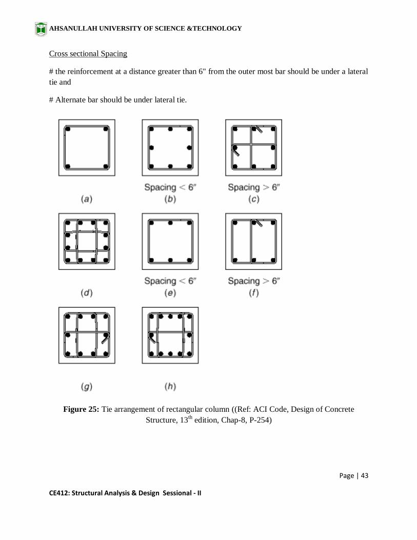
Cross sectional Spacing
# the reinforcement at a distance greater than 6" from the outer most bar should be under a lateral
tie and
# Alternate bar should be under lateral tie.
Figure 25: Tie arrangement of rectangular column ((Ref: ACI Code, Design of Concrete
Structure, 13th edition, Chap-8, P-254)

AHSANULLAH UNIVERSITY OF SCIENCE &TECHNOLOGY
Page | 44
CE412: Structural Analysis & Design Sessional - II
Figure 26: Standard bar hook for tie and stirrup. (Ref: ACI Code, Design of Concrete Structure,
13th edition, Chap-5, P-177)
Figure 27: Typical column detail

AHSANULLAH UNIVERSITY OF SCIENCE &TECHNOLOGY
Page | 45
CE412: Structural Analysis & Design Sessional - II
References
Bangladesh National Building Code (BNBC), 2006.
Concrete Technology by Nevill.
Design of Concrete Structure by Nilson (13th edition).
Design of RCC Members by WSD and USD Methods, Public Works Department (PWD),
1997.
Treasure of RCC Designs by Sushil Kumar (16th edition).
www.buildinghow.com

AHSANULLAH UNIVERSITY OF SCIENCE &TECHNOLOGY
Page | 46
CE412: Structural Analysis & Design Sessional - II
Part II
Preliminary Design of the Superstructure of a Balanced Cantilever
Bridge for Gravity loading

AHSANULLAH UNIVERSITY OF SCIENCE &TECHNOLOGY
Page | 47
CE412: Structural Analysis & Design Sessional - II
LECTURE SCHEDULE
Lecture 1
Introduction to Bridge Engineering
About Balanced Cantilever Bridge
Design of Deck Slab
Lecture 2
Design of Railing, Post and Sidewalk
Design of Interior Girder
(Dead load Calculation, Shear force diagram, Bending Moment Diagram for dead load, Influence line for shear & moment at different sections)
Lecture 3
Design of Interior Girder, Exterior Girder
(Shear force diagram, Bending Moment Diagram for live load including truck load and Lane load at different sections, Corresponding Impact shear & moment, Design of reinforcement for shear & moment)
Lecture 4
Design of Cross Girder/ Diaphram and Articulation
AHSANULLAH UNIVERSITY OF SCIENCE &TECHNOLOGY
Page | 48
CE412: Structural Analysis & Design Sessional - II
BRIDGE DESIGN SUBMISSION GUIDELINE
The Design Report shall explain the details of the design process. It shall include the
following items:
• Design Specification, Standards followed in Analysis & Design
• Loads and Load Combinations
• Design of Slab
• Design of Railing, Post and Sidewalk
• Design of Interior Girder
• Design of Exterior Girder
• Design of Diaphrams or Cross Girders
• Design of Articulation
[Note: Appropriate hand sketches showing the details of reinforcements must
accompany all design calculations.]
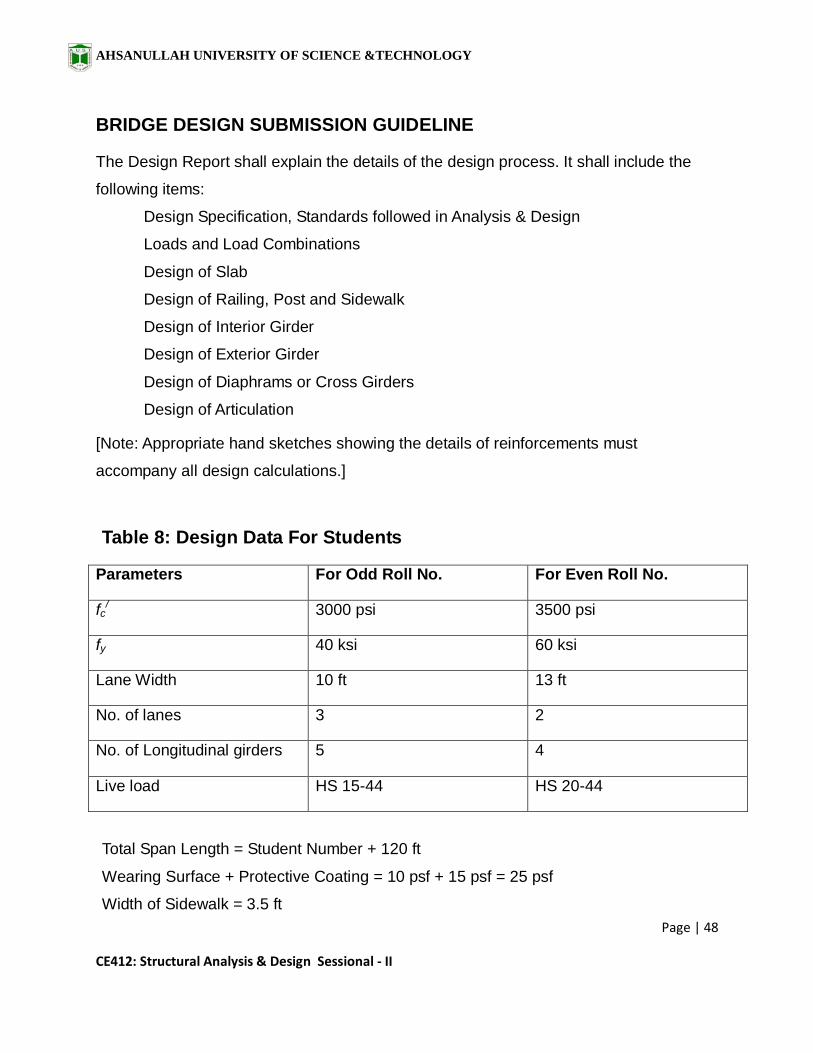
Table 8: Design Data For Students
Parameters For Odd Roll No. For Even Roll No.
fc/ 3000 psi 3500 psi
fy 40 ksi 60 ksi
Lane Width 10 ft 13 ft
No. of lanes 3 2
No. of Longitudinal girders 5 4
Live load HS 15-44 HS 20-44
Total Span Length = Student Number + 120 ft
Wearing Surface + Protective Coating = 10 psf + 15 psf = 25 psf
Width of Sidewalk = 3.5 ft
AHSANULLAH UNIVERSITY OF SCIENCE &TECHNOLOGY
Page | 49
CE412: Structural Analysis & Design Sessional - II
INTRODUCTION TO BRIDGE ENGINEERING
What is a Bridge?
• A Bridge is a structure providing passage over an obstacle without closing the
way beneath.
• The required passage may be for a road, a railway, pedestrians, a canal or a
pipeline.
Requirements of an Ideal Bridge
• Economical
• Serves the intended functions with safety and convenience
• Aesthetic elegant look
Selection of Bridge Site
• A straight reach of the river
• Steady river flow without serious whirls and cross currents
• A narrow channel with firm banks
• Suitable high banks above high flood level on each side
• Rock or other hard strata close to the river bed level
• Absence of sharp curves in the approaches
• Avoidance of excessive underwater construction
• Avoidance of expensive river training work
• Proximity to a direct alignment of the connected road

AHSANULLAH UNIVERSITY OF SCIENCE &TECHNOLOGY
Page | 50
CE412: Structural Analysis & Design Sessional - II
Choice of a type of a Bridge
• Channel Section
• Sub-soil condition
• Grades and Alignment
• Hydraulic Data
• Weather
• Navigation requirements
• Economic and Strategic considerations
• Labour availability
• Materials of Construction available
• Period of Construction
• Type of loading
• Erection Facilities
Types of Bridge
• Slab Bridge
• Deck-girder Bridge
• Balanced- Cantilever Bridge
• Suspension Bridge
• Cable-stayed Bridge
• Arch Bridge

AHSANULLAH UNIVERSITY OF SCIENCE &TECHNOLOGY
Page | 51
CE412: Structural Analysis & Design Sessional - II
Figure 28: Deck-girder Bridge – Niteroi Bridge, Rio De Janeiro, Brazil
Figure 29: Arch Bridge - Sydney Harbour Bridge, Australia

AHSANULLAH UNIVERSITY OF SCIENCE &TECHNOLOGY
Page | 52
CE412: Structural Analysis & Design Sessional - II
Figure 30: Cable-stayed Bridge – Rion Antirion Bridge, Greece
Figure 31: Suspension Bridge – Akashi Kaikyo Bridge, Japan

AHSANULLAH UNIVERSITY OF SCIENCE &TECHNOLOGY
Page | 53
CE412: Structural Analysis & Design Sessional - II
Different Parts of a Bridge
Foundation: The portion below the bed level of a river.
Substructure: The parts below the bearings level and above the foundation.
Superstructure: Components above the level of bearings.
Components above the level of bearings
Figure 32: Different parts of a Bridge
Components of a Bridge
• Deck Slab
• Girder
• Diaphram or Cross Girder
• Bearings for the decking
• Abutment, Wingwall
• Pier, Viaduct
• Foundation (i.e.Pile)
• Handrail, Curb/ Sidewalk
• Approach to the Bridge (to connect the bridge proper to the roads on either side)
Superstructure
Substructure
Foundation

AHSANULLAH UNIVERSITY OF SCIENCE &TECHNOLOGY
Page | 54
CE412: Structural Analysis & Design Sessional - II
Softwares for Bridge Design
• SAP 2000
• CSiBridge
• ADAPT ABI 2012
• Structural Bridge Design
• CRSI (Slab Bridge Designer)
• ANSYS Civil FEM Bridge
Components of a Balanced Cantilever Bridge
Figure 32: Longitudinal Profile showing Different components
AHSANULLAH UNIVERSITY OF SCIENCE &TECHNOLOGY
Page | 55
CE412: Structural Analysis & Design Sessional - II
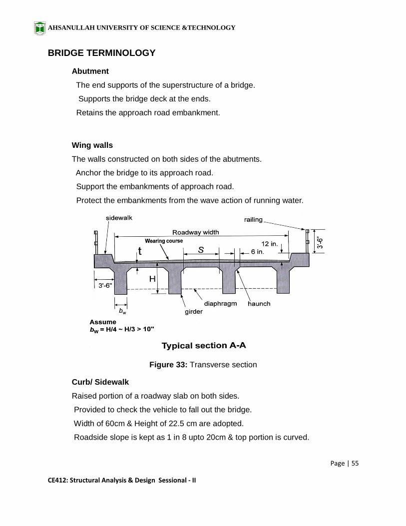
BRIDGE TERMINOLOGY
Abutment
• The end supports of the superstructure of a bridge.
• Supports the bridge deck at the ends.
• Retains the approach road embankment.
Wing walls
• The walls constructed on both sides of the abutments.
• Anchor the bridge to its approach road.
• Support the embankments of approach road.
• Protect the embankments from the wave action of running water.
Figure 33: Transverse section
Curb/ Sidewalk
• Raised portion of a roadway slab on both sides.
• Provided to check the vehicle to fall out the bridge.
• Width of 60cm & Height of 22.5 cm are adopted.
• Roadside slope is kept as 1 in 8 upto 20cm & top portion is curved.

AHSANULLAH UNIVERSITY OF SCIENCE &TECHNOLOGY
Page | 56
CE412: Structural Analysis & Design Sessional - II
Footpath
• The passage where only pedestrians are allowed to walk.
• Width may be taken as 1.5 to 2.2 metre.
Handrail
• Protective measures adopted to prevent the falling to river of the bridge users.
Pier
• Intermediate supports of the superstructure of a bridge.
• Transfer load from the superstructure to the sub-soil through the foundation.
• Obstruct the flow of water on the upstream.
• Facilitate a long bridge to be converted into segments.
Figure 34: Afflux
Afflux
• The rise in water level of the river near bridge due to obstruction created by
obstruction of piers.
• Afflux = Difference of levels of downstream and upstream water surface of
bridge.
•
AHSANULLAH UNIVERSITY OF SCIENCE &TECHNOLOGY
Page | 57
CE412: Structural Analysis & Design Sessional - II
Freeboard
• The difference between the high flood level and the level of the crown of the road
at its lowest point.
Approaches/ Embankments
• The structures that carry the road or railway track upto the bridge.
Approach Slab
• The slab provided to join the approach road with the bridge. One end rests on the
backfill of the abutment and extends into the approach at least by 3.5m.
Backfill
• Materials used to fill the space at the back of the bridge. They are the broken
stone, gravel, sand etc. and should be clean.
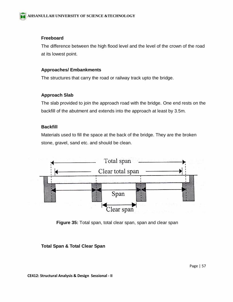
Figure 35: Total span, total clear span, span and clear span
Total Span & Total Clear Span
AHSANULLAH UNIVERSITY OF SCIENCE &TECHNOLOGY
Page | 58
CE412: Structural Analysis & Design Sessional - II
• The centre to centre distance between the end supports of a bridge is termed as
total span. Clear distance between the end supports is termed as total clear
span.
Span & Clear Span
The centre to centre distance between any two adjacent supports is termed as
span. Clear distance between any two adjacent supports is termed as clear span.
Headroom
• The distance between the highest point of the vehicle using that bridge and the
lowest point of any protruding member of the bridge.
•
High Flood Level (HFL)
• The highest water level ever recorded during a flood in a river or stream.
Low Flood Level (LFL)
• The lowest water level in a river or stream during dry weather
Mean or Ordinary Flood Level (MFL)
• The flood level that normally occurs every year. •
Loads on Bridge
• Dead load
• Live load (i.e. Vehicles and Pedestrians)
• Dynamic or Impact effect of live load
• Wind loading
• Seismic Forces
• Buoyancy
• Water current forces

AHSANULLAH UNIVERSITY OF SCIENCE &TECHNOLOGY
Page | 59
CE412: Structural Analysis & Design Sessional - II
• Thermal Forces
• Erection Forces
• Earth Pressure
• Centrifugal Forces (for curved deck)
• Longitudinal Forces (for stopping vehicle)
• Ice loading
•
AASHTO Live Load (Truck load)
Figure 36: Truck loading as per AASHTO 2002
AHSANULLAH UNIVERSITY OF SCIENCE &TECHNOLOGY
Page | 60
CE412: Structural Analysis & Design Sessional - II
ABOUT BALANCED CANTILEVER BRIDGE
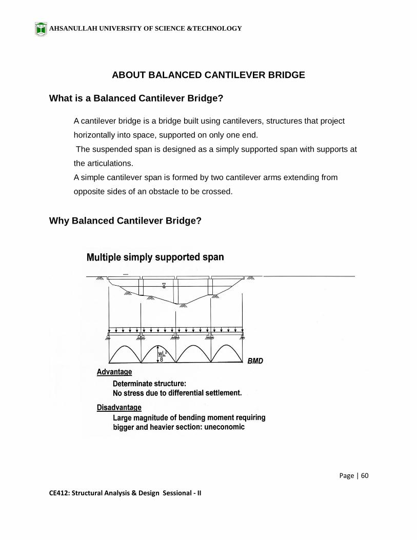
What is a Balanced Cantilever Bridge?
• A cantilever bridge is a bridge built using cantilevers, structures that project
horizontally into space, supported on only one end.
• The suspended span is designed as a simply supported span with supports at
the articulations.
• A simple cantilever span is formed by two cantilever arms extending from
opposite sides of an obstacle to be crossed.
Why Balanced Cantilever Bridge?

AHSANULLAH UNIVERSITY OF SCIENCE &TECHNOLOGY
Page | 61
CE412: Structural Analysis & Design Sessional - II
Figure 37: A bridge having simply supported span
Figure 38: A bridge having continuous span
AHSANULLAH UNIVERSITY OF SCIENCE &TECHNOLOGY
Page | 62
CE412: Structural Analysis & Design Sessional - II
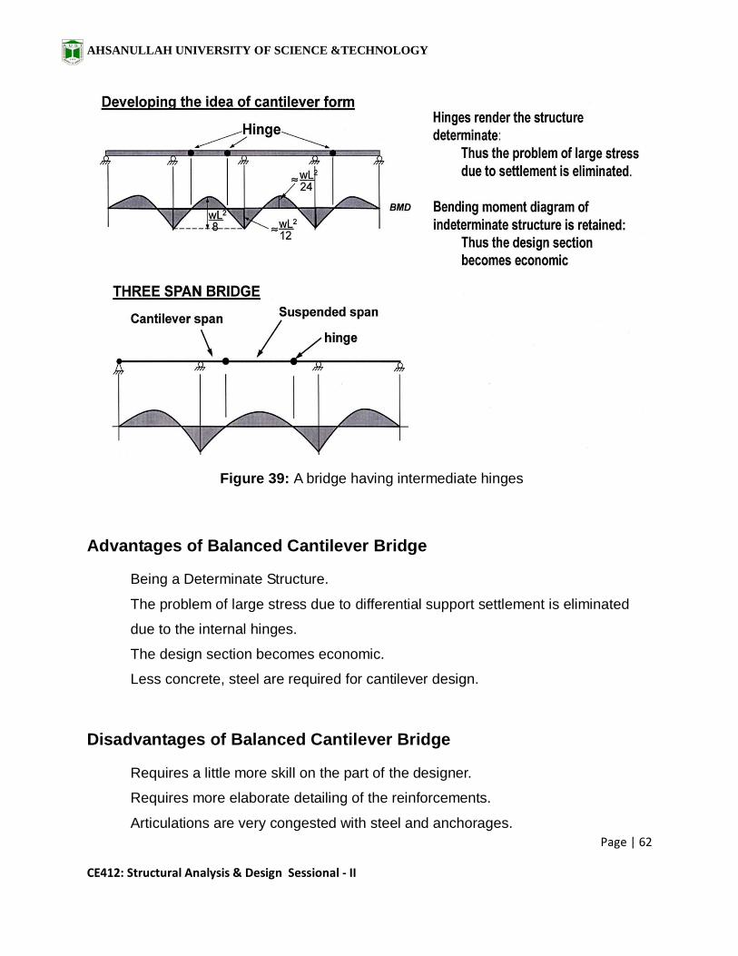
Figure 39: A bridge having intermediate hinges
Advantages of Balanced Cantilever Bridge
• Being a Determinate Structure.
• The problem of large stress due to differential support settlement is eliminated
due to the internal hinges.
• The design section becomes economic.
• Less concrete, steel are required for cantilever design.
Disadvantages of Balanced Cantilever Bridge
• Requires a little more skill on the part of the designer.
• Requires more elaborate detailing of the reinforcements.
• Articulations are very congested with steel and anchorages.

AHSANULLAH UNIVERSITY OF SCIENCE &TECHNOLOGY
Page | 63
CE412: Structural Analysis & Design Sessional - II
Example- World’s largest Cantilever Bridge
Figure 40: Quebec bridge, CANADA
Details of Quebec Bridge, CANADA
• Total length: 987 m (3,239 ft)
• Width: 29 m (94 ft) wide
• Longest span : 549 m (1,800 ft)
• Opened: December 3, 1919
• Carries: 3 lanes of roadway
1 rail line
1 pedestrian walkway
• Crosses: St. Lawrence River

AHSANULLAH UNIVERSITY OF SCIENCE &TECHNOLOGY
Page | 64
CE412: Structural Analysis & Design Sessional - II
Example - Bangladesh China Friendship Bridge
Figure 41: Bangladesh China Friendship Bridge or Mukterpur Bridge, Bangladesh
(Source: Googlemap)
Details of Bangladesh China Friendship Bridge
• Bridge Type : Pre-stressed concrete box girder
• Length : 151 m (over river Dhaleswari on Dhaka-Munshigonj road)
• Width : 10 m (carriage way - 7.5 m & sidewalk - 2x1.25 m)
• No. of Lanes : 2 Lanes
• No. of Span: 37 nos.
• No. of Abutment: 2 nos.
• No. of Piers: 38 nos.
• Type of Foundation : Pile foundation

AHSANULLAH UNIVERSITY OF SCIENCE &TECHNOLOGY
Page | 65
CE412: Structural Analysis & Design Sessional - II
Figure 42: All spans of Bangladesh China Friendship Bridge
Cantilever Span
AHSANULLAH UNIVERSITY OF SCIENCE &TECHNOLOGY
Page | 66
CE412: Structural Analysis & Design Sessional - II
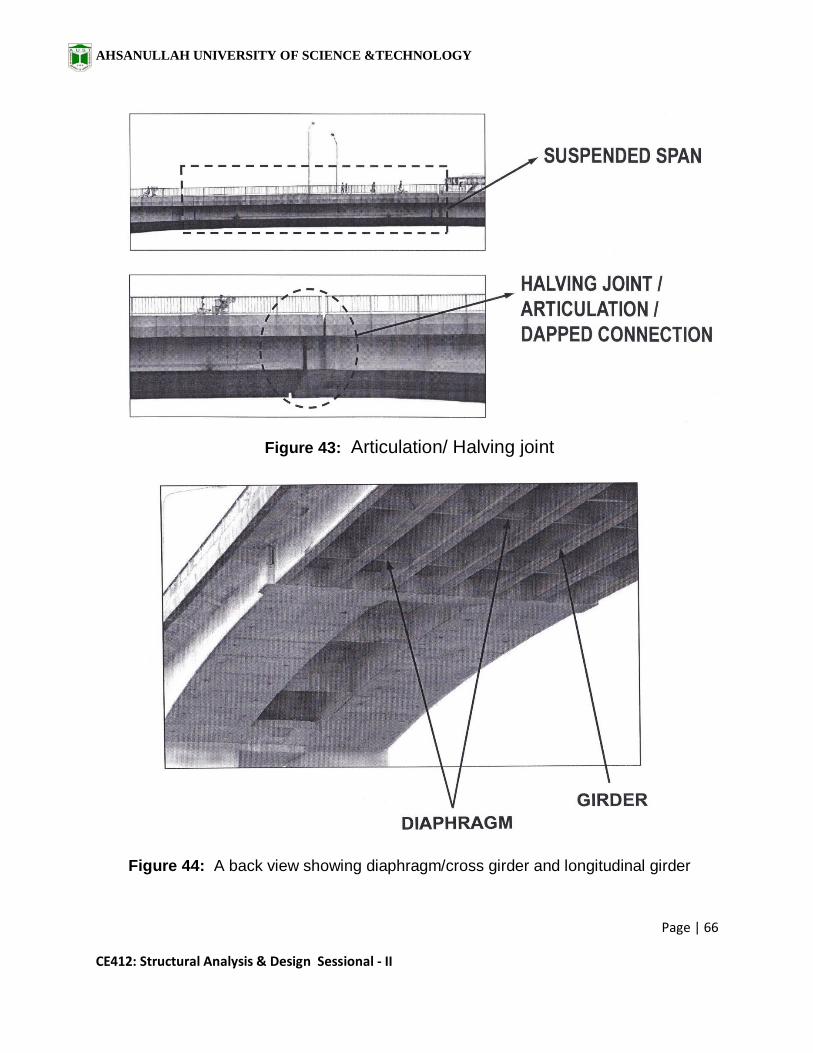
Figure 43: Articulation/ Halving joint
Figure 44: A back view showing diaphragm/cross girder and longitudinal girder
AHSANULLAH UNIVERSITY OF SCIENCE &TECHNOLOGY
Page | 67
CE412: Structural Analysis & Design Sessional - II
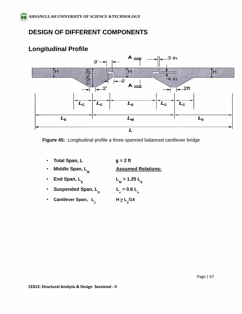
DESIGN OF DIFFERENT COMPONENTS
Longitudinal Profile
Figure 45: Longitudinal profile a three spanned balanced cantilever bridge
• Total Span, L g = 2 ft
• Middle Span, LM
Assumed Relations:
• End Span, LE L
M = 1.25 L
E
• Suspended Span, LS
Lc = 0.6 L
s
• Cantilever Span, LC
H > LS/14
AHSANULLAH UNIVERSITY OF SCIENCE &TECHNOLOGY
Page | 68
CE412: Structural Analysis & Design Sessional - II
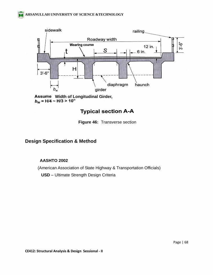
Figure 46: Transverse section
• S = [(Clear Road width – Number of Girder × Girder width) /(Number of Girder -1)] – 2 × ½ × (Haunch width)
Design Specification & Method
AASHTO 2002
(American Association of State Highway & Transportation Officials)
USD – Ultimate Strength Design Criteria
Width of Longitudinal Girder,

AHSANULLAH UNIVERSITY OF SCIENCE &TECHNOLOGY
Page | 69
CE412: Structural Analysis & Design Sessional - II
DESIGN OF DECK SLAB
Figure 47: Reinforcement in Deck Slab
Design Steps
Assume Slab thickness, t
Determine self-weight of slab = (150 × t /12) psf
Consider wearing surface
Determine total dead load in psf , wDL
(Self weight of slab + load of wearing surface
Determine Dead load Moment , MDL
= + (1/9 )wDL
s2
AHSANULLAH UNIVERSITY OF SCIENCE &TECHNOLOGY
Page | 70
CE412: Structural Analysis & Design Sessional - II
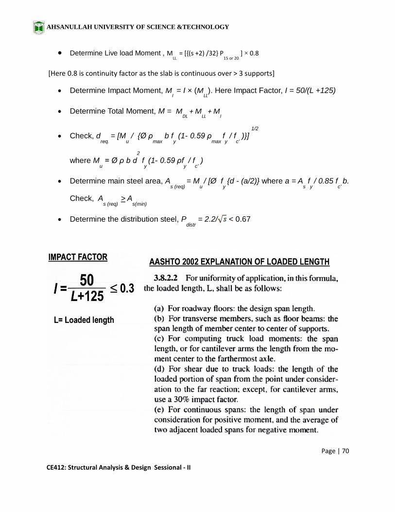
Determine Live load Moment , MLL
= [{(s +2) /32} P15 or 20
] × 0.8
[Here 0.8 is continuity factor as the slab is continuous over > 3 supports]
Determine Impact Moment, MI = I × (M
LL). Here Impact Factor, I = 50/(L +125)
Determine Total Moment, M = MDL
+ MLL
+ MI
Check, dreq.
= [Mu / {Ø ρ
max b f
y (1- 0.59 ρ
max fy / f
c' )}]
1/2
where Mu = Ø ρ b d
2
fy (1- 0.59 ρf
y / f
c' )
Determine main steel area, As (req)
= Mu / [Ø f
y {d - (a/2)} where a = A
s f
y / 0.85 f
c' b.
Check, As (req)
> As(min)
Determine the distribution steel, Pdistr
= 2.2/ < 0.67

AHSANULLAH UNIVERSITY OF SCIENCE &TECHNOLOGY
Page | 71
CE412: Structural Analysis & Design Sessional - II
DESIGN OF RAILING
Figure 48: Railing and Post
• Each railing shall be designed for 50 lb/ft uniformly distributed live load acting
simultaneously in both vertical and horizontal direction.
• Opening between rails < 6 inch for portion 27 in. vertically from walkway surface.
• Opening between rails < 8 inch for portion above 27 in. from walkway surface.
Design Steps:
• Assume, 5in. X 5in. Railing
• Consider Live load on each railing = 50lb/ft
• Determine Dead load per unit length
• Determine total load wT per unit length
• Determine Maximum Moment = (1/10) wT l2
• Determine steel Area As .

AHSANULLAH UNIVERSITY OF SCIENCE &TECHNOLOGY
Page | 72
CE412: Structural Analysis & Design Sessional - II
DESIGN OF RAIL POST
Figure 49: Rail Post
• Minimum Height of Rail Post = 42 inch.
• Rail posts shall be designed for only a lateral load of P = 50 L acting at the top of
the post where L= Spacing of the posts.
AHSANULLAH UNIVERSITY OF SCIENCE &TECHNOLOGY
Page | 73
CE412: Structural Analysis & Design Sessional - II
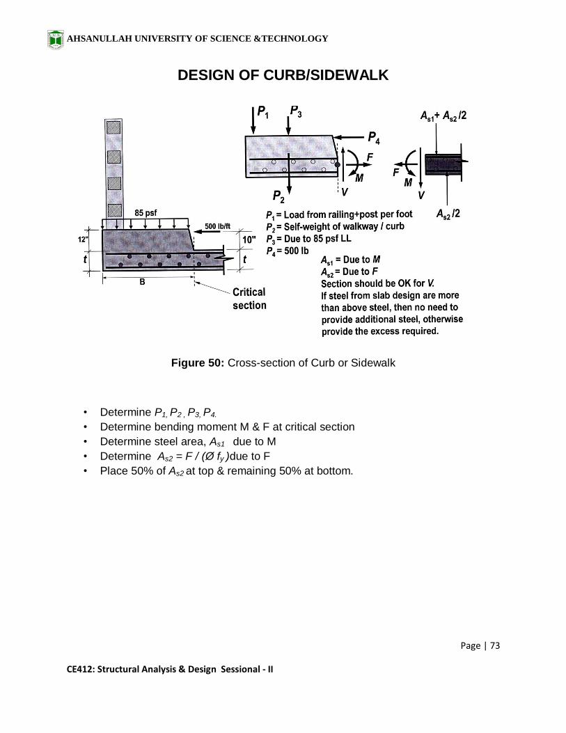
DESIGN OF CURB/SIDEWALK
Figure 50: Cross-section of Curb or Sidewalk
• Determine P1, P2 , P3, P4.
• Determine bending moment M & F at critical section
• Determine steel area, As1 due to M
• Determine As2 = F / (Ø fy )due to F
• Place 50% of As2 at top & remaining 50% at bottom.

AHSANULLAH UNIVERSITY OF SCIENCE &TECHNOLOGY
Page | 74
CE412: Structural Analysis & Design Sessional - II
DESIGN OF INTERIOR GIRDER
Figure 51: Longitudinal and transverse profile of Interior Girder

AHSANULLAH UNIVERSITY OF SCIENCE &TECHNOLOGY
Page | 75
CE412: Structural Analysis & Design Sessional - II
Figure 52: Dead Loads and different sections of Interior Girder

AHSANULLAH UNIVERSITY OF SCIENCE &TECHNOLOGY
Page | 76
CE412: Structural Analysis & Design Sessional - II
Table 9: Determining depth of interior girder at different sections
Section Distance from
Centreline (1loc.) (ft)
Depth of Girder, y
(inch)
Depth of Variable
part (inch)
1
2
3
4
5
6
7
8
9
10
11
12
13
14

AHSANULLAH UNIVERSITY OF SCIENCE &TECHNOLOGY
Page | 77
CE412: Structural Analysis & Design Sessional - II
Dead load Analysis of Interior Girder
• Determine Dead load coming from Self weight of slab & wearing surface.
• Determine self weight of Longitudinal Girder from constant & variable part.
• Determine self weight of cross girder/diaphram.
Dead Load from Variable part of Girder
Figure 53: Variable part of Interior Girder

AHSANULLAH UNIVERSITY OF SCIENCE &TECHNOLOGY
Page | 78
CE412: Structural Analysis & Design Sessional - II
Table 10: Calculation of necessary data for Variable Part of Interior Girder
Section
wij (ft)
yi
(in.)
yj
(in.)
Load
from
Varying
part (lb)
C.G. from
left
Location
of load
from CL
(1loc.) (ft)
1-2
2-3
3-4
4-5
5-6
6-7
7-8
8-9
9-10
10-11
11-12
12-13
13-14

AHSANULLAH UNIVERSITY OF SCIENCE &TECHNOLOGY
Page | 79
CE412: Structural Analysis & Design Sessional - II
Table 11: Determining concentrated load of cross girder/diaphram
Load of Diaphram Depth of Cross
girder (in.)
Width of Girder, bd
(inch)
Load (lb)
P1
P2
P3
P4
P5
P6
Figure 54: Typical SFD and BMD of interior Girder due to dead loading
AHSANULLAH UNIVERSITY OF SCIENCE &TECHNOLOGY
Page | 80
CE412: Structural Analysis & Design Sessional - II
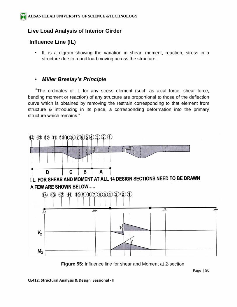
Live Load Analysis of Interior Girder
Influence Line (IL)
• IL is a digram showing the variation in shear, moment, reaction, stress in a
structure due to a unit load moving across the structure.
• Miller Breslay’s Principle
“The ordinates of IL for any stress element (such as axial force, shear force,
bending moment or reaction) of any structure are proportional to those of the deflection
curve which is obtained by removing the restrain corresponding to that element from
structure & introducing in its place, a corresponding deformation into the primary
structure which remains.”
Figure 55: Influence line for shear and Moment at 2-section

AHSANULLAH UNIVERSITY OF SCIENCE &TECHNOLOGY
Page | 81
CE412: Structural Analysis & Design Sessional - II
Figure 56: Influence line for shear and Moment at 6&10-section
Figure 57: The dimension SG for live load multiplier

AHSANULLAH UNIVERSITY OF SCIENCE &TECHNOLOGY
Page | 82
CE412: Structural Analysis & Design Sessional - II
Figure 58: Forward and Reverse truck loading
Figure 59: Truck direction for Maximum positive and negative Shear
AHSANULLAH UNIVERSITY OF SCIENCE &TECHNOLOGY
Page | 83
CE412: Structural Analysis & Design Sessional - II
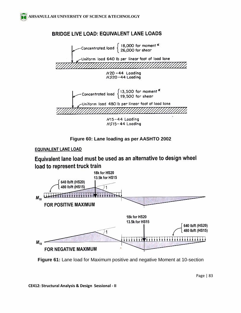
Figure 60: Lane loading as per AASHTO 2002
Figure 61: Lane load for Maximum positive and negative Moment at 10-section
AHSANULLAH UNIVERSITY OF SCIENCE &TECHNOLOGY
Page | 84
CE412: Structural Analysis & Design Sessional - II
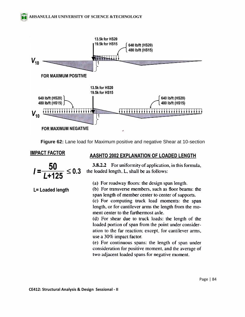
Figure 62: Lane load for Maximum positive and negative Shear at 10-section

AHSANULLAH UNIVERSITY OF SCIENCE &TECHNOLOGY
Page | 85
CE412: Structural Analysis & Design Sessional - II
Explanation of Loaded length (L) in Impact Formula
Figure 63: The length L for determining Impact Factor I

AHSANULLAH UNIVERSITY OF SCIENCE &TECHNOLOGY
Page | 86
CE412: Structural Analysis & Design Sessional - II
Table 12: Design shear of Interior Girder at different sections

AHSANULLAH UNIVERSITY OF SCIENCE &TECHNOLOGY
Page | 87
CE412: Structural Analysis & Design Sessional - II
Table 13: Design Moment of Interior Girder at different sections
Note: Use Dead load with its sign to combine with both positive and negative live load
moments

AHSANULLAH UNIVERSITY OF SCIENCE &TECHNOLOGY
Page | 88
CE412: Structural Analysis & Design Sessional - II
Flexural Reinforcement Design of Interior Girder
• Determine Effective width beff. for Interior Girder.
• Choose minimum of Span/4, Centre to centre distance of Girder,
(16 x Slab thickness) + Girder Width for beff .
• Consider the Design Moments for each sections.
• Determine Steel Area As for maximum design moment.
• Bar Cut-off will be done where required.
Table 14: Required flexural reinforcement of Interior Girder

AHSANULLAH UNIVERSITY OF SCIENCE &TECHNOLOGY
Page | 89
CE412: Structural Analysis & Design Sessional - II
Shear Reinforcement Design of Interior Girder
• Determine Shear Strength of Concrete,
Ø Vc = Ø 2 bw d
• Determine required spacing of shear reinforcement,
sreq. = Ø Av fy d / (Vu - Ø Vc)
• Also determine Maximum spacing for the check,
smax. = Av fy / (50 bw ) or, d/2 or, 24 inch (which one is the smallest)
Table 15: Required Shear reinforcement of Interior Girder
Section
Design Shear
(kip)
Ø Vc (kip)
Av
Srequired
(in.)
Sprovided
(in.)
1 2 3 4 5 6 7 8 9
10 11 12 13 14

AHSANULLAH UNIVERSITY OF SCIENCE &TECHNOLOGY
Page | 90
CE412: Structural Analysis & Design Sessional - II
DESIGN OF EXTERIOR GIRDER
Figure 64: Loads considered for Exterior Girder
AHSANULLAH UNIVERSITY OF SCIENCE &TECHNOLOGY
Page | 91
CE412: Structural Analysis & Design Sessional - II
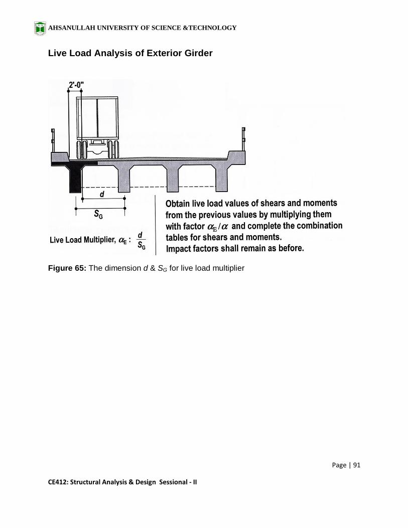
Live Load Analysis of Exterior Girder
Figure 65: The dimension d & SG for live load multiplier
AHSANULLAH UNIVERSITY OF SCIENCE &TECHNOLOGY
Page | 92
CE412: Structural Analysis & Design Sessional - II
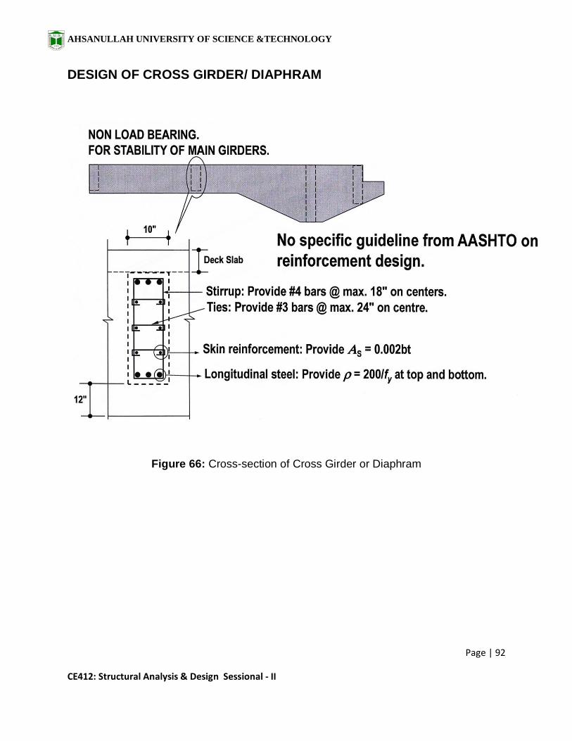
DESIGN OF CROSS GIRDER/ DIAPHRAM
Figure 66: Cross-section of Cross Girder or Diaphram

AHSANULLAH UNIVERSITY OF SCIENCE &TECHNOLOGY
Page | 93
CE412: Structural Analysis & Design Sessional - II
ARTICULATION
• The connection between the suspended span and the edge of the cantilever is
called „Articulation‟.
• The bearings at articulations can be in the form of sliding plates, roller-rocker
arrangement or elastomeric pads.
Figure 67: Possible Cracks near Articulation

AHSANULLAH UNIVERSITY OF SCIENCE &TECHNOLOGY
Page | 94
CE412: Structural Analysis & Design Sessional - II
Figure 68: Clearance requirement around bearing pad
Figure 69: Minimum Edge distance and expansion gap at articulation

AHSANULLAH UNIVERSITY OF SCIENCE &TECHNOLOGY
Page | 95
CE412: Structural Analysis & Design Sessional - II
Figure 70: Widening of Girder section for providing enlarged section near articulation
AHSANULLAH UNIVERSITY OF SCIENCE &TECHNOLOGY
Page | 96
CE412: Structural Analysis & Design Sessional - II
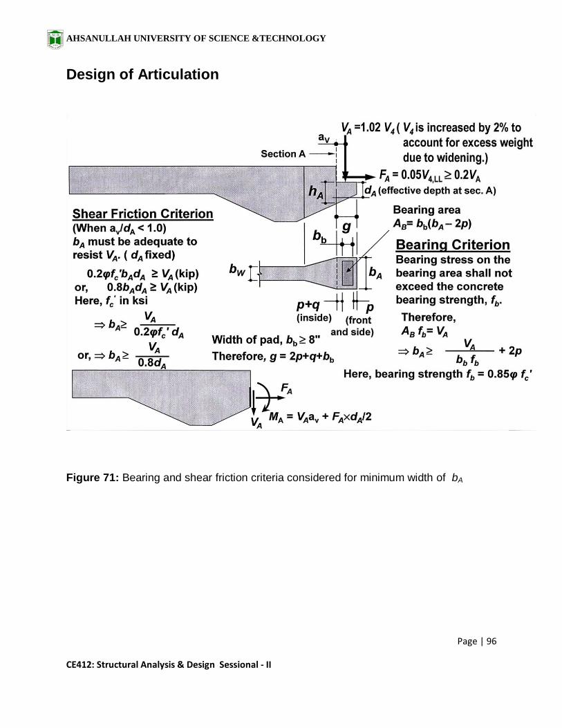
Design of Articulation
Figure 71: Bearing and shear friction criteria considered for minimum width of bA

AHSANULLAH UNIVERSITY OF SCIENCE &TECHNOLOGY
Page | 97
CE412: Structural Analysis & Design Sessional - II
Figure 72: Elevation and plan view of Articulation showing reinforcement
Design Steps
Determine flexural steel area As1 based on moment MA .
Determine steel area As2 based on FA.
Determine steel area Ash based on direct tension of VA.
Determine required spacing s.

AHSANULLAH UNIVERSITY OF SCIENCE &TECHNOLOGY
Page | 98
CE412: Structural Analysis & Design Sessional - II
DETAILING OF ARTICULATION
Figure 73: Detailing of reinforcement

AHSANULLAH UNIVERSITY OF SCIENCE &TECHNOLOGY
Page | 99
CE412: Structural Analysis & Design Sessional - II
REFERENCES
Lecture Note on CE 412, Prepared by Dr. Khan Mahmud Amanat,
Professor, Dept. of Civil Engg., BUET.
Lecture Note on CE 412, Prepared by Mr. Ruhul Amin, Assistant
Professor, Dept. of Civil Engg., BUET.
AASHTO Code 2002.
Nilson A.H., Darwin D., Dolan C.W. (2003), Design of Concrete
Structures, 13th edition, Mc. Graw Hill.