Embed Size (px)
Citation preview
SERVICE MANUALSERVICE MANUALSERVICE MANUALSERVICE MANUALSERVICE MANUAL
AH-06-01.1AH-06-01.1AH-06-01.1AH-06-01.1AH-06-01.111111(Replaces AH-06-01.10)December-2011
IMPORIMPORIMPORIMPORIMPORTTTTTANTANTANTANTANT: Before using this equipment,: Before using this equipment,: Before using this equipment,: Before using this equipment,: Before using this equipment,
carefully read SAFETY PRECAUTIONS,carefully read SAFETY PRECAUTIONS,carefully read SAFETY PRECAUTIONS,carefully read SAFETY PRECAUTIONS,carefully read SAFETY PRECAUTIONS,
starting on page 1, and all instructions in thisstarting on page 1, and all instructions in thisstarting on page 1, and all instructions in thisstarting on page 1, and all instructions in thisstarting on page 1, and all instructions in this
manual. Keep this Service Manual for futuremanual. Keep this Service Manual for futuremanual. Keep this Service Manual for futuremanual. Keep this Service Manual for futuremanual. Keep this Service Manual for future
reference.reference.reference.reference.reference.
VECTVECTVECTVECTVECTORORORORORTMTMTMTMTM R SERIES R SERIES R SERIES R SERIES R SERIES
CASCADE APPLICACASCADE APPLICACASCADE APPLICACASCADE APPLICACASCADE APPLICATTTTTORSORSORSORSORS
MODELS:MODELS:MODELS:MODELS:MODELS:
79500 R90 Cascade - Solventborne79500 R90 Cascade - Solventborne79500 R90 Cascade - Solventborne79500 R90 Cascade - Solventborne79500 R90 Cascade - Solventborne
79501 R70 Cascade - Solventborne79501 R70 Cascade - Solventborne79501 R70 Cascade - Solventborne79501 R70 Cascade - Solventborne79501 R70 Cascade - Solventborne
79523 R90 Cascade - W79523 R90 Cascade - W79523 R90 Cascade - W79523 R90 Cascade - W79523 R90 Cascade - Waterborneaterborneaterborneaterborneaterborne
For Use With 79513-1XX Control UnitFor Use With 79513-1XX Control UnitFor Use With 79513-1XX Control UnitFor Use With 79513-1XX Control UnitFor Use With 79513-1XX Control Unit
Service Manual Price:Service Manual Price:Service Manual Price:Service Manual Price:Service Manual Price: €40.00 (Euro)40.00 (Euro)40.00 (Euro)40.00 (Euro)40.00 (Euro)
$50.00 (U.S.)$50.00 (U.S.)$50.00 (U.S.)$50.00 (U.S.)$50.00 (U.S.)

AH-06-01.11
NOTE:NOTE:NOTE:NOTE:NOTE: This manual has been changed from revision AH-06-01.10AH-06-01.10AH-06-01.10AH-06-01.10AH-06-01.10 to revision AH-06-01.11. AH-06-01.11. AH-06-01.11. AH-06-01.11. AH-06-01.11.Reasons for this change are noted under “Manual Change Summary” inside the backcover of this manual.
AH-06-01.11
SAFETY:SAFETY:SAFETY:SAFETY:SAFETY:
SAFETY PRECAUTIONS.........................................................................................................HAZARDS / SAFEGUARDS.....................................................................................................
PAGEPAGEPAGEPAGEPAGE
INTRODUCTION:INTRODUCTION:INTRODUCTION:INTRODUCTION:INTRODUCTION:
CONTENTSCONTENTSCONTENTSCONTENTSCONTENTS
GENERAL DESCRIPTION........................................................................................................79500 R90 CASCADE SOLVENTBORNE SPECIFICATIONS..............................................79501 R70 CASCADE SOLVENTBORNE SPECIFICATIONS...............................................R90/70 CASCADE SOLVENTBORNE ELECTROSTATICSPRAY APPLICATOR FEATURES..........................................................................................79513-1XX 9050 POWER SUPPLY ELECTRICAL SPECIFICATIONS..................................79513-XXX CASCADE CONTROL UNIT FEATURES............................................................
1-41-41-41-41-4
13-1813-1813-1813-1813-18
12-4
131515
161718
Vector R Series Cascade Applicators - Contents
INSTALLATION:INSTALLATION:INSTALLATION:INSTALLATION:INSTALLATION:
79500 R90 / 79501 R70 SOLVENTBORNE INSTALLATION..................................................TYPICAL SOLVENTBORNE INSTALLATION.........................................................................79527-00 9050 MOUNTING KIT / PARTS LIST.......................................................................79527-00 9050 CASCADE ENCLOSURES ............................................................................ELECTRICAL NOISE................................................................................................................I/O CONNECTIONS..................................................................................................................AC INPUT CONNECTIONS.....................................................................................................INTERLOCKS............................................................................................................................RELAY CONTACT OUTPUTS.................................................................................................LOW VOLTAGE CABLE...........................................................................................................FILTERS.....................................................................................................................................PAINT PREPARATION.............................................................................................................SPRAY PATTERN ADJUSTMENT..........................................................................................APPLICATOR TO TARGET DISTANCE..................................................................................FLUID NOZZLE / AIR CAP SELECTION CHARTS.................................................................ROUND SPRAY PERFORMANCE CHART............................................................................
19-3219-3219-3219-3219-32
1919-212122232424-2525-2626-272828-2930303031-3232
(Continued On Next Page)(Continued On Next Page)(Continued On Next Page)(Continued On Next Page)(Continued On Next Page)
ATEX/FM:ATEX/FM:ATEX/FM:ATEX/FM:ATEX/FM:
EUROPEAN ATEX DIRECTIVE...............................................................................................
EUROPEAN ATEX LABELS.....................................................................................................
FM CONFIGURATION DRAWINGS.........................................................................................
5-125-125-125-125-12
5
6
7-12
33-3833-3833-3833-3833-38OPERATION:OPERATION:OPERATION:OPERATION:OPERATION:
POWERING UP CONTROL UNIT............................................................................................SETPOINT VOLTAGE...............................................................................................................LOCKOUTS...............................................................................................................................KV TEST JUMPER....................................................................................................................BASIC OPERATION..................................................................................................................FAULT DESCRIPTIONS...........................................................................................................
3333-3434-363636-3737-38
AH-06-01.11
Vector R Series Cascade Applicators - Contents
PAGEPAGEPAGEPAGEPAGE
MAINTENANCE:MAINTENANCE:MAINTENANCE:MAINTENANCE:MAINTENANCE:
SUITABLE SOLVENTS FOR CLEANINGVECTOR R90/70 APPLICATORS..............................................................................................ROUTINE SCHEDULE...............................................................................................................APPLICATOR ASSEMBLY CLEANING PROCEDURE..........................................................FLUSHING PROCEDURES.......................................................................................................APPLICATOR REPAIR...............................................................................................................TO REMOVE THE APPLICATOR FROM THE WORK SITE...................................................AIR CAP......................................................................................................................................FLUID NOZZLE..........................................................................................................................NEEDLE / ELECTRODE............................................................................................................NEEDLE / ELECTRODE RESISTANCE TESTING..................................................................BARREL ASSEMBLY.................................................................................................................DISASSEMBLY / REASSEMBLY OF BARREL WITHSTANDARD FLUID NEEDLE PACKINGS................................................................................DISASSEMBLY / REASSEMBLY OF BARREL WITHTHE 2K FLUID NEEDLE PACKINGS........................................................................................HANDLE / PLUG ASSEMBLY....................................................................................................TROUBLESHOOTING GUIDE..................................................................................................
39-6239-6239-6239-6239-62
3940-4141-4243434444-4545-46464747-48
48-51
51-5656-5859-61
PARTS IDENTIFICATION:PARTS IDENTIFICATION:PARTS IDENTIFICATION:PARTS IDENTIFICATION:PARTS IDENTIFICATION: 63-8663-8663-8663-8663-86
R90/70 CASCADE SOLVENTBORNE APPLICATORBREAKDOWN / PARTS LIST....................................................................................................VECTOR R90/70 CASCADE SOLVENTBORNE MODEL IDENTIFICATION.........................R90 (78628-11) AND R70 (78628-12) CASCADE NEEDLE SHAFT(STANDARD PACKINGS) / PARTS LIST.................................................................................R90 (79599-01) AND R70 (79599-02) CASCADE NEEDLE SHAFT(2K PACKINGS) / PARTS LIST..................................................................................................79513-1XX CONTROL UNIT / PARTS LIST..............................................................................WATERBORNE APPLICATOR MODEL 79523 SECTIONWATERBORNE APPLICATOR MODEL 79523 SECTIONWATERBORNE APPLICATOR MODEL 79523 SECTIONWATERBORNE APPLICATOR MODEL 79523 SECTIONWATERBORNE APPLICATOR MODEL 79523 SECTION
- R90 CASCADE WATERBORNE ELECTROSTATICSPRAY APPLICATOR FEATURES ....................................................................................
- 79523 R90 CASCADE WATERBORNE SPECIFICATIONS..............................................- 79513-1XX 9050 POWER SUPPLY ELECTRICAL SPECIFICATIONS.............................- R90 CASCADE WATERBORNE TYPICAL INSTALLATION.............................................- WATERBORNE ISOLATION SYSTEM INSTALLATION GUIDELINES............................- WATERBORNE HOSE FITTING INSTALLATION..............................................................- WATERBORNE FLUID DELIVERY COMPONENTS / PARTS LIST.................................- VECTOR R90 CASCADE WATERBORNE MODEL IDENTIFICATION...........................
VECTOR AIR HOSE OPTIONS / PARTS LIST........................................................................VECTOR FLUID HOSE OPTIONS / PARTS LIST....................................................................VECTOR APPLICATOR COVER OPTIONS / PARTS LIST....................................................VECTOR SWIRL NOZZLE OPTIONS / PARTS LIST...............................................................VECTOR FLUID TUBE OPTIONS / PARTS LIST.....................................................................LOW VOLTAGE CABLE OPTION / PARTS LIST.....................................................................TRANS-TECH. ATOMIZATION / PARTS LIST.........................................................................79555 TRANS-TECH. CONVERSION KITS AVAILABLE........................................................ACCESSORIES FOR ECON FLUSH BOX COMPATIBILITY (OPTIONAL)...........................VECTOR CASCADE APPLICATORS RECOMMENDED SPARE PARTS.............................
63-6566
67
6869
727373747575-7677-787980808181818182838385-86
WARRANTY POLICIES:WARRANTY POLICIES:WARRANTY POLICIES:WARRANTY POLICIES:WARRANTY POLICIES: 8787878787
LIMITED WARRANTY................................................................................................................ 87

AH-06-01.11
NOTESNOTESNOTESNOTESNOTES
AH-06-01.11
SAFETY PRECAUTIONSSAFETY PRECAUTIONSSAFETY PRECAUTIONSSAFETY PRECAUTIONSSAFETY PRECAUTIONS
Before operating, maintaining or servicing anyITWRansburg electrostatic coating system, readand understand all of the technical and safetyliterature for your ITW Ransburg products. Thismanual contains information that is important foryou to know and understand. This informationrelates to USER SAFETY and PREVENTINGEQUIPMENT PROBLEMS. To help you recognizethis information, we use the following symbols.Please pay particular attention to these sections.
A WARNING! states information to alert youA WARNING! states information to alert youA WARNING! states information to alert youA WARNING! states information to alert youA WARNING! states information to alert you
to a situation that might cause serious injuryto a situation that might cause serious injuryto a situation that might cause serious injuryto a situation that might cause serious injuryto a situation that might cause serious injury
if instructions are not followed.if instructions are not followed.if instructions are not followed.if instructions are not followed.if instructions are not followed.
A CAUTION! states information that tellsA CAUTION! states information that tellsA CAUTION! states information that tellsA CAUTION! states information that tellsA CAUTION! states information that tells
how to prevent damage to equipment or howhow to prevent damage to equipment or howhow to prevent damage to equipment or howhow to prevent damage to equipment or howhow to prevent damage to equipment or how
to avoid a situation that might cause minorto avoid a situation that might cause minorto avoid a situation that might cause minorto avoid a situation that might cause minorto avoid a situation that might cause minor
injury.injury.injury.injury.injury.
A NOTE is information relevant to theA NOTE is information relevant to theA NOTE is information relevant to theA NOTE is information relevant to theA NOTE is information relevant to the
procedure in progress.procedure in progress.procedure in progress.procedure in progress.procedure in progress.
While this manual lists standard specificationsand service procedures, some minor deviationsmay be found between this literature and yourequipment. Differences in local codes and plantrequirements, material delivery requirements, etc.,make such variations inevitable. Compare thismanual with your system installation drawingsand appropriate Ransburg equipmentmanuals to reconcile such differences.
Careful study and continued use of this manual willprovide a better understanding of the equipmentand process, resulting in more efficient operation,longer trouble-free service and faster, easiertroubleshooting. If you do not have the manualsand safety literature for your ITW Ransburg system,contact your local ITW Ransburg representativeor ITW Ransburg.
SAFETYSAFETYSAFETYSAFETYSAFETY
>The user MUSTMUSTMUSTMUSTMUST read and be familiar
with the Safety Section in this manual andthe ITW Ransburg safety literature thereinidentified.
> This manual MUSTMUSTMUSTMUSTMUST be read and thor-
oughly understood by ALLALLALLALLALL personnel whooperate, clean or maintain this equipment!Special care should be taken to ensure thatthe WARNINGSWARNINGSWARNINGSWARNINGSWARNINGS and safety requirementsfor operating and servicing the equipmentare followed. The user should be aware ofand adhere to ALLALLALLALLALL local building and firecodes and ordinances as well as NFPA-NFPA-NFPA-NFPA-NFPA-
33 SAFETY STANDARD, or applica-33 SAFETY STANDARD, or applica-33 SAFETY STANDARD, or applica-33 SAFETY STANDARD, or applica-33 SAFETY STANDARD, or applica-
ble country safety standards ble country safety standards ble country safety standards ble country safety standards ble country safety standards prior toinstalling, operating, and/or servicing thisequipment.
W A R N I N GW A R N I N GW A R N I N GW A R N I N GW A R N I N G!!!!!
>The hazards shown on the following
page may occur during the normal use ofthis equipment. Please read the hazardchart beginning on page 2.
W A R N I N GW A R N I N GW A R N I N GW A R N I N GW A R N I N G!!!!!
11111
Vector R Series Cascade Applicators - Safety
AH-06-01.11
Vector R Series Cascade Applicators - Safety
22222
Spray AreaSpray AreaSpray AreaSpray AreaSpray Area
AREAAREAAREAAREAAREA
Tells where hazards
may occur.
HAZARDHAZARDHAZARDHAZARDHAZARD
Tells what the hazard is.
SAFEGUARDSSAFEGUARDSSAFEGUARDSSAFEGUARDSSAFEGUARDS
Tells how to avoid the hazard.
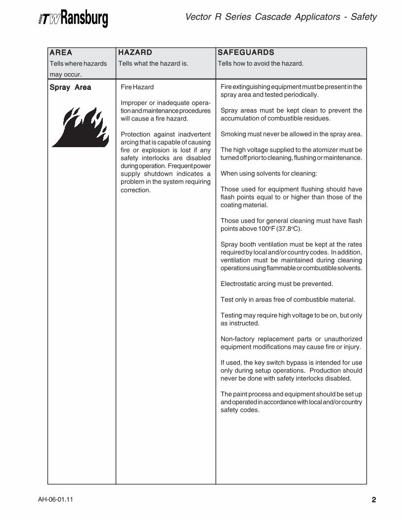
Fire Hazard
Improper or inadequate opera-tion and maintenance procedureswill cause a fire hazard.
Protection against inadvertentarcing that is capable of causingfire or explosion is lost if anysafety interlocks are disabledduring operation. Frequent powersupply shutdown indicates aproblem in the system requiring
correction.
Fire extinguishing equipment must be present in thespray area and tested periodically.
Spray areas must be kept clean to prevent theaccumulation of combustible residues.
Smoking must never be allowed in the spray area.
The high voltage supplied to the atomizer must beturned off prior to cleaning, flushing or maintenance.
When using solvents for cleaning:
Those used for equipment flushing should haveflash points equal to or higher than those of thecoating material.
Those used for general cleaning must have flashpoints above 100oF (37.8oC).
Spray booth ventilation must be kept at the ratesrequired by local and/or country codes. In addition,ventilation must be maintained during cleaningoperations using flammable or combustible solvents.
Electrostatic arcing must be prevented.
Test only in areas free of combustible material.
Testing may require high voltage to be on, but onlyas instructed.
Non-factory replacement parts or unauthorizedequipment modifications may cause fire or injury.
If used, the key switch bypass is intended for useonly during setup operations. Production shouldnever be done with safety interlocks disabled.
The paint process and equipment should be set upand operated in accordance with local and/or countrysafety codes.
AH-06-01.11
Vector R Series Cascade Applicators - Safety
33333
AREAAREAAREAAREAAREA
Tells where hazards
may occur.
HAZARDHAZARDHAZARDHAZARDHAZARD
Tells what the hazard is.
SAFEGUARDSSAFEGUARDSSAFEGUARDSSAFEGUARDSSAFEGUARDS
Tells how to avoid the hazard.
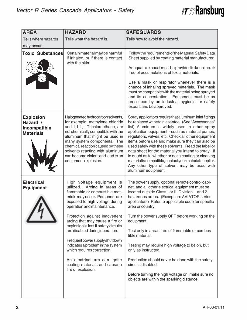
ElectricalElectricalElectricalElectricalElectrical
EquipmentEquipmentEquipmentEquipmentEquipment
High voltage equipment isutilized. Arcing in areas offlammable or combustible mat-erials may occur. Personnel areexposed to high voltage duringoperation and maintenance.
Protection against inadvertentarcing that may cause a fire orexplosion is lost if safety circuitsare disabled during operation.
Frequent power supply shutdownindicates a problem in the systemwhich requires correction.
An electrical arc can ignitecoating materials and cause afire or explosion.
The power supply, optional remote control cabi-net, and all other electrical equipment must belocated outside Class I or II, Division 1 and 2hazardous areas. (Exception: AVIATOR seriesapplicators) Refer to applicable code for specificarea or country.
Turn the power supply OFF before working on theequipment.
Test only in areas free of flammable or combus-tible material.
Testing may require high voltage to be on, butonly as instructed.
Production should never be done with the safetycircuits disabled.
Before turning the high voltage on, make sure noobjects are within the sparking distance.
ExplosionExplosionExplosionExplosionExplosion
Hazard /Hazard /Hazard /Hazard /Hazard /
IncompatibleIncompatibleIncompatibleIncompatibleIncompatible
MaterialsMaterialsMaterialsMaterialsMaterials
Halogenated hydrocarbon solvents,for example: methylene chlorideand 1,1,1, - Trichloroethane, arenot chemically compatible with thealuminum that might be used inmany system components. Thechemical reaction caused by thesesolvents reacting with aluminumcan become violent and lead to anequipment explosion.
Spray applicators require that aluminum inlet fittingsbe replaced with stainless steel. (See "Accessories"list) Aluminum is widely used in other sprayapplication equipment - such as material pumps,regulators, valves, etc. Check all other equipmentitems before use and make sure they can also beused safely with these solvents. Read the label ordata sheet for the material you intend to spray. Ifin doubt as to whether or not a coating or cleaningmaterial is compatible, contact your material supplier.Any other type of solvent may be used withaluminum equipment.
Toxic SubstancesToxic SubstancesToxic SubstancesToxic SubstancesToxic Substances Certain material may be harmfulif inhaled, or if there is contactwith the skin.
Follow the requirements of the Material Safety DataSheet supplied by coating material manufacturer.
Adequate exhaust must be provided to keep the airfree of accumulations of toxic materials.
Use a mask or respirator whenever there is achance of inhaling sprayed materials. The maskmust be compatible with the material being sprayedand its concentration. Equipment must be asprescribed by an industrial hygienist or safetyexpert, and be approved.
AH-06-01.11
Vector R Series Cascade Applicators - Safety
44444
AREAAREAAREAAREAAREA
Tells where hazards
may occur.
HAZARDHAZARDHAZARDHAZARDHAZARD
Tells what the hazard is.
SAFEGUARDSSAFEGUARDSSAFEGUARDSSAFEGUARDSSAFEGUARDS
Tells how to avoid the hazard.
Spray AreaSpray AreaSpray AreaSpray AreaSpray Area
General Use andGeneral Use andGeneral Use andGeneral Use andGeneral Use and
MaintenanceMaintenanceMaintenanceMaintenanceMaintenance
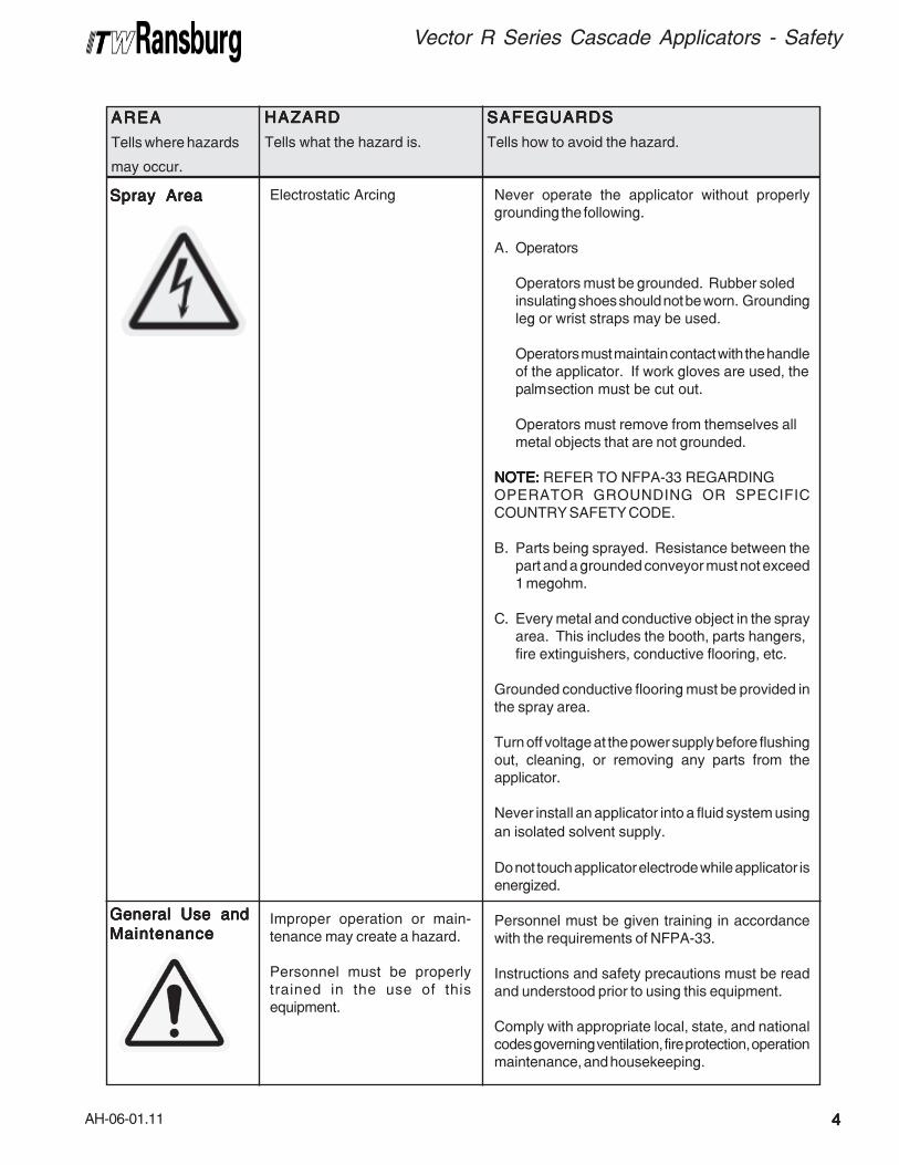
Electrostatic Arcing
Improper operation or main-tenance may create a hazard.
Personnel must be properlytrained in the use of thisequipment.
Never operate the applicator without properlygrounding the following.
A. Operators
Operators must be grounded. Rubber soledinsulating shoes should not be worn. Groundingleg or wrist straps may be used.
Operators must maintain contact with the handleof the applicator. If work gloves are used, thepalmsection must be cut out.
Operators must remove from themselves allmetal objects that are not grounded.
NOTE:NOTE:NOTE:NOTE:NOTE: REFER TO NFPA-33 REGARDINGOPERATOR GROUNDING OR SPECIFICCOUNTRY SAFETY CODE.
B. Parts being sprayed. Resistance between thepart and a grounded conveyor must not exceed1 megohm.
C. Every metal and conductive object in the sprayarea. This includes the booth, parts hangers,fire extinguishers, conductive flooring, etc.
Grounded conductive flooring must be provided inthe spray area.
Turn off voltage at the power supply before flushingout, cleaning, or removing any parts from theapplicator.
Never install an applicator into a fluid system using
an isolated solvent supply.
Do not touch applicator electrode while applicator isenergized.
Personnel must be given training in accordancewith the requirements of NFPA-33.
Instructions and safety precautions must be readand understood prior to using this equipment.
Comply with appropriate local, state, and nationalcodes governing ventilation, fire protection, operationmaintenance, and housekeeping.

AH-06-01.11
Vector R Series Cascade Applicators - Atex/FM
55555
EUROPEAN AEUROPEAN AEUROPEAN AEUROPEAN AEUROPEAN ATEX DIRECTIVE 94/9/EC, ANNEX II, 1.0.6TEX DIRECTIVE 94/9/EC, ANNEX II, 1.0.6TEX DIRECTIVE 94/9/EC, ANNEX II, 1.0.6TEX DIRECTIVE 94/9/EC, ANNEX II, 1.0.6TEX DIRECTIVE 94/9/EC, ANNEX II, 1.0.6
The following instructions apply to equipmentcovered by certificate number Sira 06ATEX5282X:
1. The equipment may be used with flammablegases and vapors with apparatus groups II andwith temperature class T6.
2. The equipment is only certified for use in ambienttemperatures in the range +12.8°C to +40°C andshould not be used outside this range.
3. Installation shall be carried out by suitably trainedpersonnel in accordance with the applicable codeof practice e.g. EN 60079-14:1997.
4. Inspection and maintenance of this equipmentshall be carried out by suitably trained personnelin accordance with the applicable code of practicee.g. EN 60079-17.
5. Repair of this equipment shall be carried out bysuitable trained personnel in accordance with theapplicable code of practice e.g. EN 60079-19.
6. Putting into service, use, assembling, andadjustment of the equipment shall be fitted bysuitably trained personnel in accordance with themanufacturer's documentation.
Refer to the "Table of Contents" of this servicemanual.
a. Installationb. Operationc. Maintenanced. Parts Identification
7. Components to be incorporated into or used asreplacement parts of the equipment shall be fittedby suitably trained personnel in accordance withthe manufacturer's documentation.
8. The certification of this equipment relies uponthe following materials used in its construction:
If the equipment is likely to come into contact withaggressive substances, then it is the responsibilityof the user to take suitable precautions that preventit from being adversely affected, thus ensuringthat the type of protection provided by the equipmentis not compromised.
Aggressive substances: e.g. acidic liquids orgases that may attack metals, or solvents thatmay affect polymeric materials.
Suitable precautions: e.g. regular checks as partof routine inspections or establishing from thematerial's data sheets that it is resistant to specificchemicals.
Refer to "Specifications" in the "Introduction"section:
a. All fluid passages contain stainless steel or nylon fittings.
b. High voltage cascade is encapsulated with a solvent resistant epoxy.
9. A recapitulation of the certification marking isdetailed in the "ATEX" section, on the next page,drawing numbers: 79496, 79515, 79516, 79535,79536, and 79539.
10. The characteristics of the equipment shall bedetailed e.g. electrical, pressure, and voltageparameters.
The manufacturer should note that, on beingThe manufacturer should note that, on beingThe manufacturer should note that, on beingThe manufacturer should note that, on beingThe manufacturer should note that, on being
put into service, the equipment must beput into service, the equipment must beput into service, the equipment must beput into service, the equipment must beput into service, the equipment must be
accompanied by a translation of theaccompanied by a translation of theaccompanied by a translation of theaccompanied by a translation of theaccompanied by a translation of the
instructions in the language or languages ofinstructions in the language or languages ofinstructions in the language or languages ofinstructions in the language or languages ofinstructions in the language or languages of
the country in which the equipment is to bethe country in which the equipment is to bethe country in which the equipment is to bethe country in which the equipment is to bethe country in which the equipment is to be
used and by the instructions in the originalused and by the instructions in the originalused and by the instructions in the originalused and by the instructions in the originalused and by the instructions in the original
language.language.language.language.language.
AH-06-01.11
Vector R Series Cascade Applicators - Atex/FM
66666
Label 79516-70Label 79516-70Label 79516-70Label 79516-70Label 79516-70
Label 79515Label 79515Label 79515Label 79515Label 79515
Label 79516-91Label 79516-91Label 79516-91Label 79516-91Label 79516-91
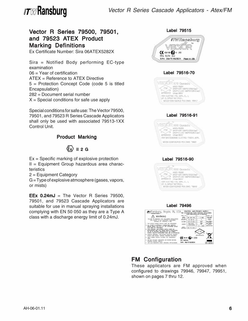
VVVVVector R Series 79500, 79501,ector R Series 79500, 79501,ector R Series 79500, 79501,ector R Series 79500, 79501,ector R Series 79500, 79501,
and 79523 Aand 79523 Aand 79523 Aand 79523 Aand 79523 ATEX ProductTEX ProductTEX ProductTEX ProductTEX Product
Marking DefinitionsMarking DefinitionsMarking DefinitionsMarking DefinitionsMarking DefinitionsEx Certificate Number: Sira 06ATEX5282X
Sira = Notified Body performing EC-typeexamination06 = Year of certificationATEX = Reference to ATEX Directive5 = Protection Concept Code (code 5 is titledEncapsulation)282 = Document serial numberX = Special conditions for safe use apply
Special conditions for safe use: The Vector 79500,79501, and 79523 R Series Cascade Applicatorsshall only be used with associated 79513-1XXControl Unit.
Product MarkingProduct MarkingProduct MarkingProduct MarkingProduct Marking
II 2 GII 2 GII 2 GII 2 GII 2 G
Ex = Specific marking of explosive protectionII = Equipment Group hazardous area charac-teristics2 = Equipment CategoryG = Type of explosive atmosphere (gases, vapors,or mists)
EEx 0.24mJEEx 0.24mJEEx 0.24mJEEx 0.24mJEEx 0.24mJ = The Vector R Series 79500,79501, and 79523 Cascade Applicators aresuitable for use in manual spraying installationscomplying with EN 50 050 as they are a Type Aclass with a discharge energy limit of 0.24mJ.
Label 79516-90Label 79516-90Label 79516-90Label 79516-90Label 79516-90
Label 79496Label 79496Label 79496Label 79496Label 79496
FM ConfigurationFM ConfigurationFM ConfigurationFM ConfigurationFM ConfigurationThese applicators are FM approved whenconfigured to drawings 79946, 79947, 79951,shown on pages 7 thru 12.

AH-06-01.11
Vector R Series Cascade Applicators - Atex/FM
VECTOR R90 CASCADE, SOLVENT BASED
79500 - ABCDEBASE
MODEL NO.OPTION
DESIGNATIONS
(ORDERING INFORMATION ONLY)
CONFIGURATION DWG. 79946 REV B
"B" DESIGNATIONS
"E" DESIGNATIONS
"C" DESIGNATIONS
"D" DESIGNATIONS
"A" DESIGNATIONS
77777
AH-06-01.11
Vector R Series Cascade Applicators - Atex/FM
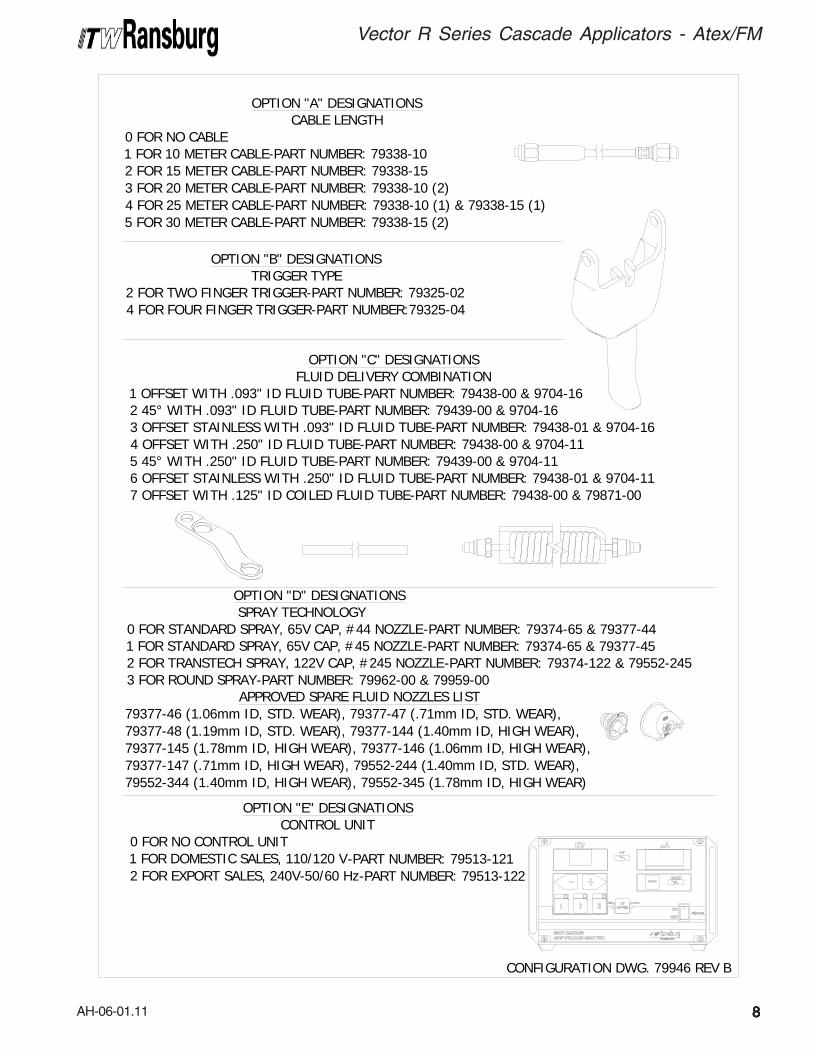
CONFIGURATION DWG. 79946 REV B
OPTION "A" DESIGNATIONSCABLE LENGTH
0 FOR NO CABLE1 FOR 10 METER CABLE-PART NUMBER: 79338-102 FOR 15 METER CABLE-PART NUMBER: 79338-153 FOR 20 METER CABLE-PART NUMBER: 79338-10 (2)4 FOR 25 METER CABLE-PART NUMBER: 79338-10 (1) & 79338-15 (1)5 FOR 30 METER CABLE-PART NUMBER: 79338-15 (2)
OPTION "C" DESIGNATIONSFLUID DELIVERY COMBINATION
1 OFFSET WITH .093" ID FLUID TUBE-PART NUMBER: 79438-00 & 9704-162 45° WITH .093" ID FLUID TUBE-PART NUMBER: 79439-00 & 9704-163 OFFSET STAINLESS WITH .093" ID FLUID TUBE-PART NUMBER: 79438-01 & 9704-164 OFFSET WITH .250" ID FLUID TUBE-PART NUMBER: 79438-00 & 9704-115 45° WITH .250" ID FLUID TUBE-PART NUMBER: 79439-00 & 9704-116 OFFSET STAINLESS WITH .250" ID FLUID TUBE-PART NUMBER: 79438-01 & 9704-117 OFFSET WITH .125" ID COILED FLUID TUBE-PART NUMBER: 79438-00 & 79871-00
OPTION "B" DESIGNATIONSTRIGGER TYPE
2 FOR TWO FINGER TRIGGER-PART NUMBER: 79325-024 FOR FOUR FINGER TRIGGER-PART NUMBER:79325-04
OPTION "D" DESIGNATIONS SPRAY TECHNOLOGY0 FOR STANDARD SPRAY, 65V CAP, #44 NOZZLE-PART NUMBER: 79374-65 & 79377-441 FOR STANDARD SPRAY, 65V CAP, #45 NOZZLE-PART NUMBER: 79374-65 & 79377-452 FOR TRANSTECH SPRAY, 122V CAP, #245 NOZZLE-PART NUMBER: 79374-122 & 79552-2453 FOR ROUND SPRAY-PART NUMBER: 79962-00 & 79959-00
OPTION "E" DESIGNATIONSCONTROL UNIT
0 FOR NO CONTROL UNIT1 FOR DOMESTIC SALES, 110/120 V-PART NUMBER: 79513-1212 FOR EXPORT SALES, 240V-50/60 Hz-PART NUMBER: 79513-122
APPROVED SPARE FLUID NOZZLES LIST79377-46 (1.06mm ID, STD. WEAR), 79377-47 (.71mm ID, STD. WEAR),79377-48 (1.19mm ID, STD. WEAR), 79377-144 (1.40mm ID, HIGH WEAR),79377-145 (1.78mm ID, HIGH WEAR), 79377-146 (1.06mm ID, HIGH WEAR),79377-147 (.71mm ID, HIGH WEAR), 79552-244 (1.40mm ID, STD. WEAR),79552-344 (1.40mm ID, HIGH WEAR), 79552-345 (1.78mm ID, HIGH WEAR)
88888
AH-06-01.11
Vector R Series Cascade Applicators - Atex/FM
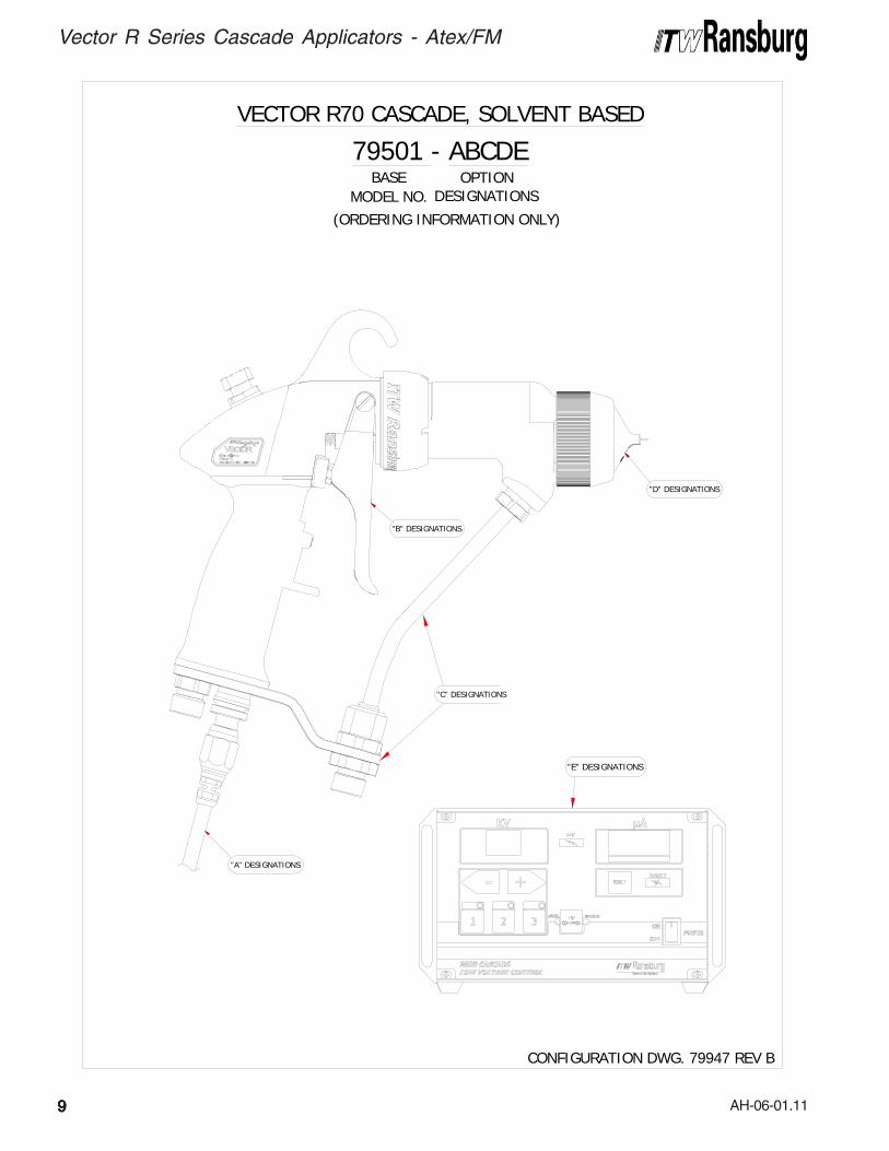
"B" DESIGNATIONS
"C" DESIGNATIONS
"D" DESIGNATIONS
"A" DESIGNATIONS
"E" DESIGNATIONS
VECTOR R70 CASCADE, SOLVENT BASED
79501 - ABCDEBASE
MODEL NO.OPTION
DESIGNATIONS
(ORDERING INFORMATION ONLY)
CONFIGURATION DWG. 79947 REV B
99999
AH-06-01.11
Vector R Series Cascade Applicators - Atex/FM
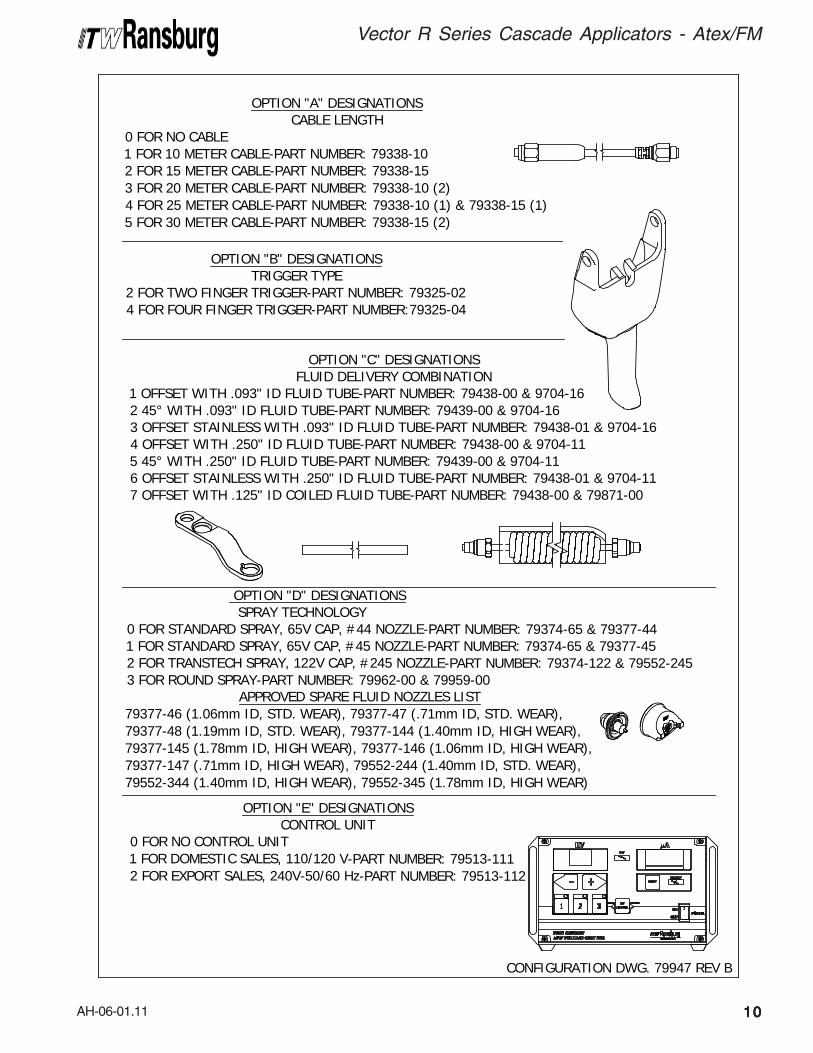
APPROVED SPARE FLUID NOZZLES LIST79377-46 (1.06mm ID, STD. WEAR), 79377-47 (.71mm ID, STD. WEAR),79377-48 (1.19mm ID, STD. WEAR), 79377-144 (1.40mm ID, HIGH WEAR),79377-145 (1.78mm ID, HIGH WEAR), 79377-146 (1.06mm ID, HIGH WEAR),79377-147 (.71mm ID, HIGH WEAR), 79552-244 (1.40mm ID, STD. WEAR),79552-344 (1.40mm ID, HIGH WEAR), 79552-345 (1.78mm ID, HIGH WEAR)
CONFIGURATION DWG. 79947 REV B
OPTION "A" DESIGNATIONSCABLE LENGTH
0 FOR NO CABLE1 FOR 10 METER CABLE-PART NUMBER: 79338-102 FOR 15 METER CABLE-PART NUMBER: 79338-153 FOR 20 METER CABLE-PART NUMBER: 79338-10 (2)4 FOR 25 METER CABLE-PART NUMBER: 79338-10 (1) & 79338-15 (1)5 FOR 30 METER CABLE-PART NUMBER: 79338-15 (2)
OPTION "C" DESIGNATIONSFLUID DELIVERY COMBINATION
1 OFFSET WITH .093" ID FLUID TUBE-PART NUMBER: 79438-00 & 9704-162 45° WITH .093" ID FLUID TUBE-PART NUMBER: 79439-00 & 9704-163 OFFSET STAINLESS WITH .093" ID FLUID TUBE-PART NUMBER: 79438-01 & 9704-164 OFFSET WITH .250" ID FLUID TUBE-PART NUMBER: 79438-00 & 9704-115 45° WITH .250" ID FLUID TUBE-PART NUMBER: 79439-00 & 9704-116 OFFSET STAINLESS WITH .250" ID FLUID TUBE-PART NUMBER: 79438-01 & 9704-117 OFFSET WITH .125" ID COILED FLUID TUBE-PART NUMBER: 79438-00 & 79871-00
OPTION "B" DESIGNATIONSTRIGGER TYPE
2 FOR TWO FINGER TRIGGER-PART NUMBER: 79325-024 FOR FOUR FINGER TRIGGER-PART NUMBER:79325-04
OPTION "D" DESIGNATIONS SPRAY TECHNOLOGY0 FOR STANDARD SPRAY, 65V CAP, #44 NOZZLE-PART NUMBER: 79374-65 & 79377-441 FOR STANDARD SPRAY, 65V CAP, #45 NOZZLE-PART NUMBER: 79374-65 & 79377-452 FOR TRANSTECH SPRAY, 122V CAP, #245 NOZZLE-PART NUMBER: 79374-122 & 79552-2453 FOR ROUND SPRAY-PART NUMBER: 79962-00 & 79959-00
OPTION "E" DESIGNATIONSCONTROL UNIT
0 FOR NO CONTROL UNIT1 FOR DOMESTIC SALES, 110/120 V-PART NUMBER: 79513-1112 FOR EXPORT SALES, 240V-50/60 Hz-PART NUMBER: 79513-112
1010101010
AH-06-01.11
Vector R Series Cascade Applicators - Atex/FM
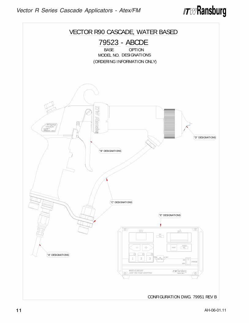
VECTOR R90 CASCADE, WATER BASED
79523 - ABCDEBASE
MODEL NO.OPTION
DESIGNATIONS
(ORDERING INFORMATION ONLY)
CONFIGURATION DWG. 79951 REV B
"B" DESIGNATIONS
"E" DESIGNATIONS
"C" DESIGNATIONS
"D" DESIGNATIONS
"A" DESIGNATIONS
1111111111
AH-06-01.11
Vector R Series Cascade Applicators - Atex/FM
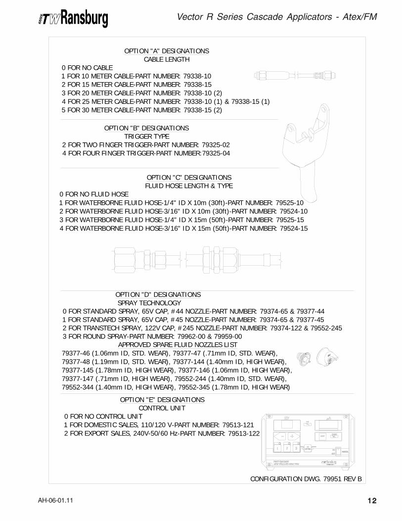
OPTION "C" DESIGNATIONSFLUID HOSE LENGTH & TYPE
0 FOR NO FLUID HOSE1 FOR WATERBORNE FLUID HOSE-1/4" ID X 10m (30ft)-PART NUMBER: 79525-102 FOR WATERBORNE FLUID HOSE-3/16" ID X 10m (30ft)-PART NUMBER: 79524-103 FOR WATERBORNE FLUID HOSE-1/4" ID X 15m (50ft)-PART NUMBER: 79525-154 FOR WATERBORNE FLUID HOSE-3/16" ID X 15m (50ft)-PART NUMBER: 79524-15
CONFIGURATION DWG. 79951 REV B
OPTION "A" DESIGNATIONSCABLE LENGTH
0 FOR NO CABLE1 FOR 10 METER CABLE-PART NUMBER: 79338-102 FOR 15 METER CABLE-PART NUMBER: 79338-153 FOR 20 METER CABLE-PART NUMBER: 79338-10 (2)4 FOR 25 METER CABLE-PART NUMBER: 79338-10 (1) & 79338-15 (1)5 FOR 30 METER CABLE-PART NUMBER: 79338-15 (2)
OPTION "B" DESIGNATIONSTRIGGER TYPE
2 FOR TWO FINGER TRIGGER-PART NUMBER: 79325-024 FOR FOUR FINGER TRIGGER-PART NUMBER:79325-04
OPTION "D" DESIGNATIONS SPRAY TECHNOLOGY0 FOR STANDARD SPRAY, 65V CAP, #44 NOZZLE-PART NUMBER: 79374-65 & 79377-441 FOR STANDARD SPRAY, 65V CAP, #45 NOZZLE-PART NUMBER: 79374-65 & 79377-452 FOR TRANSTECH SPRAY, 122V CAP, #245 NOZZLE-PART NUMBER: 79374-122 & 79552-2453 FOR ROUND SPRAY-PART NUMBER: 79962-00 & 79959-00
OPTION "E" DESIGNATIONSCONTROL UNIT
0 FOR NO CONTROL UNIT1 FOR DOMESTIC SALES, 110/120 V-PART NUMBER: 79513-1212 FOR EXPORT SALES, 240V-50/60 Hz-PART NUMBER: 79513-122
APPROVED SPARE FLUID NOZZLES LIST79377-46 (1.06mm ID, STD. WEAR), 79377-47 (.71mm ID, STD. WEAR),79377-48 (1.19mm ID, STD. WEAR), 79377-144 (1.40mm ID, HIGH WEAR),79377-145 (1.78mm ID, HIGH WEAR), 79377-146 (1.06mm ID, HIGH WEAR),79377-147 (.71mm ID, HIGH WEAR), 79552-244 (1.40mm ID, STD. WEAR),79552-344 (1.40mm ID, HIGH WEAR), 79552-345 (1.78mm ID, HIGH WEAR)
1212121212
AH-06-01.11
GENERAL DESCRIPTIONGENERAL DESCRIPTIONGENERAL DESCRIPTIONGENERAL DESCRIPTIONGENERAL DESCRIPTION
The Vector Vector Vector Vector Vector TMTMTMTMTM R90/70 R90/70 R90/70 R90/70 R90/70 Spray Applicator Spray Applicator Spray Applicator Spray Applicator Spray Applicator pro-cess is an air-atomized method for electrostaticallyapplying product coatings. The Vector R90/R70Spray Applicator system applies a high voltageDC charge to the applicator electrode, creating anelectrostatic field between the atomizer and thetarget object.
Vector™ R90Vector™ R90Vector™ R90Vector™ R90Vector™ R90 Cascade Spray ApplicatorCascade Spray ApplicatorCascade Spray ApplicatorCascade Spray ApplicatorCascade Spray Applicator(see Figure 1) applies a -85 kV DC charge to thecoating materials at the point of atomization. The
Vector™Vector™Vector™Vector™Vector™ R70 Cascade R70 Cascade R70 Cascade R70 Cascade R70 Cascade Spray ApplicatorSpray ApplicatorSpray ApplicatorSpray ApplicatorSpray Applicatorapplies a -65 kV charge. This electrostatic chargeallows a more efficient, uniform application ofcoating material to the front, edges, sides, andback of products. It is highly suitable for applyingcoatings to a variety of surface configurations:large targets, small parts, tubular wares, concaveand recessed parts, etc. Because it is a groundedfluid system (for solvent based systems), it ishighly suitable for applying a wide range of solventreduced coatings such as enamels, lacquers,epoxies, etc. The 79523 model is available toaccomodate waterborne materials.
A regulated pressure fluid system delivers coatingmaterial to the atomizer. At the time of triggeringthe applicator, fan and atomization air is introduced,which atomizes the coating material into a spraymist. The atomized spray particles under theinfluence of the electrostatic field becomeelectrically charged. The charged particles areattracted to, and deposited on, the target object.The forces between the charged particles and thegrounded target are sufficient to turn most normaloverspray around and deposit it on the backsurface of the target. Therefore, a high percentageof the coating is deposited on the target.
One of the many features of the Vector R90/70applicator system is that the electrical energy,which is available from the resistive chargingelectrode, is limited to the optimum level of safety
INTRODUCTIONINTRODUCTIONINTRODUCTIONINTRODUCTIONINTRODUCTION
Vector R Series Cascade Applicators - Introduction
1313131313
and efficiency. The system is incapable of releasingsufficient electrical or thermal energy during normaloperating conditions to cause ignition of specifichazardous materials in their most easily ignitedconcentrations in air.
The control unit or power supply provides voltageoutput to the applicator and contains controls forAC on/off, high voltage adjust, and displays kVand μA in real time.
As the applicator electrode approaches ground,the control unit and applicator circuitry cause thehigh voltage to approach zero while the currentapproaches its maximum value.
>When more than one waterborne appli-
cator is fed from a common isolated fluidsupply, there is a potential for electricalenergy discharge through any other applica-tors when one applicator is triggered. De-pending upon the system capacity, thisdischarge could be hazardous. It is best toonly install one applicator per isolatedsupply.
W A R N I N GW A R N I N GW A R N I N GW A R N I N GW A R N I N G!!!!!

AH-06-01.11
Vector R Series Cascade Applicators - Introduction
1414141414
NOTESNOTESNOTESNOTESNOTES
AH-06-01.11
Vector R Series Cascade Applicators - Introduction
1515151515
Fluid FlowFluid FlowFluid FlowFluid FlowFluid Flow
Capacity:Capacity:Capacity:Capacity:Capacity: 1000 cc/minute**
Operating Pressure (Air Spray)Operating Pressure (Air Spray)Operating Pressure (Air Spray)Operating Pressure (Air Spray)Operating Pressure (Air Spray)
Fluid:Fluid:Fluid:Fluid:Fluid: (0-6.9 bar) 0-100 psi
Air :Air :Air :Air :Air : (0-6.9 bar) 0-100 psi
Ambient Temp.:Ambient Temp.:Ambient Temp.:Ambient Temp.:Ambient Temp.: 40°C to 12.8°C
Consumption:Consumption:Consumption:Consumption:Consumption: 510 slpm (18 SCFM) @ 3.4 bar (50 psig) inlet
Sound Level:Sound Level:Sound Level:Sound Level:Sound Level: 92dB (A) @ 50 psig inlet,1m from applicator
** This reflects the maximum fluid volume the appli-cator can deliver. The maximum spray volume thatcan be effectively atomized depends on fluid rheol-ogy, spray technology, and finish quality required.
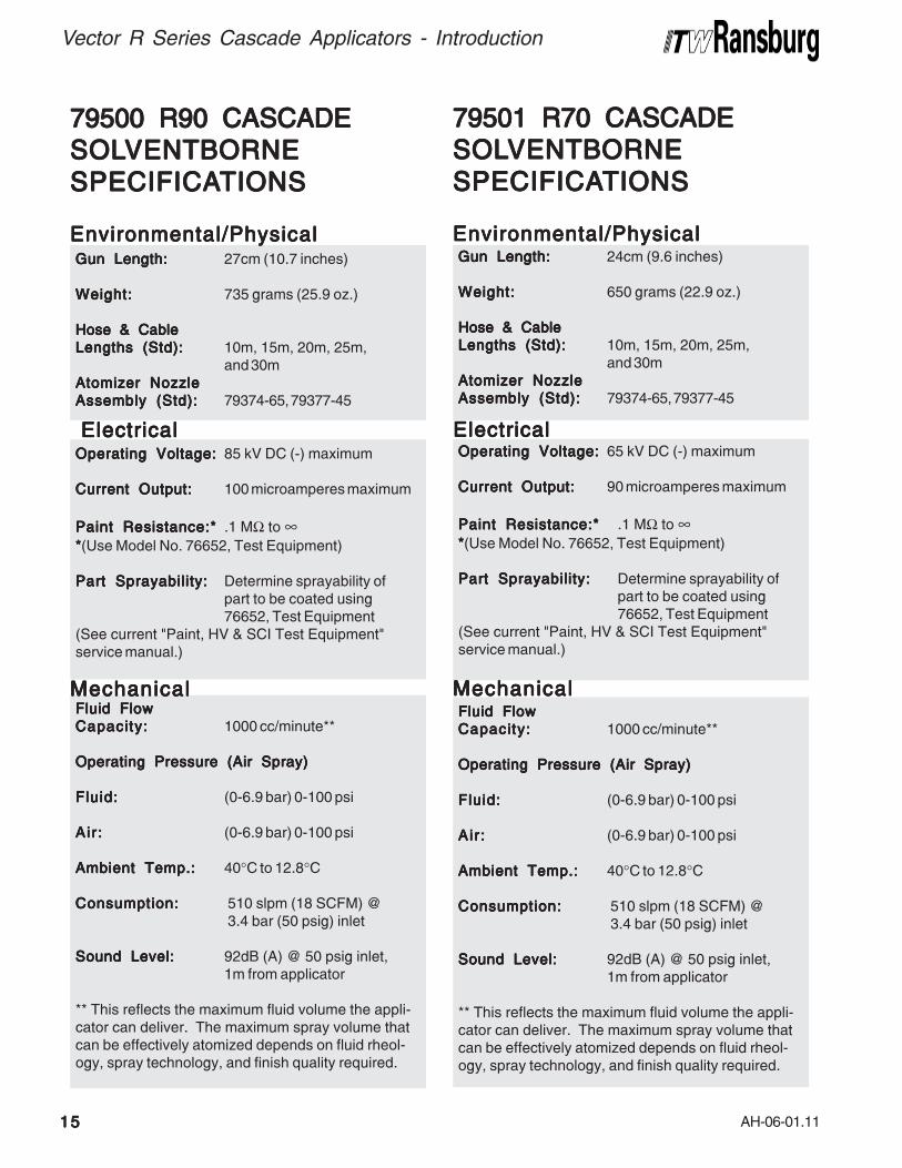
Gun Length:Gun Length:Gun Length:Gun Length:Gun Length: 27cm (10.7 inches)
Weight:Weight:Weight:Weight:Weight: 735 grams (25.9 oz.)
Hose & CableHose & CableHose & CableHose & CableHose & Cable
Lengths (Std):Lengths (Std):Lengths (Std):Lengths (Std):Lengths (Std): 10m, 15m, 20m, 25m,and 30m
Atomizer NozzleAtomizer NozzleAtomizer NozzleAtomizer NozzleAtomizer Nozzle
Assembly (Std):Assembly (Std):Assembly (Std):Assembly (Std):Assembly (Std): 79374-65, 79377-45
Operating Voltage:Operating Voltage:Operating Voltage:Operating Voltage:Operating Voltage: 85 kV DC (-) maximum
Current Output:Current Output:Current Output:Current Output:Current Output: 100 microamperes maximum
Paint Resistance:*Paint Resistance:*Paint Resistance:*Paint Resistance:*Paint Resistance:* .1 MΩ to ∞*****(Use Model No. 76652, Test Equipment)
Part Sprayability:Part Sprayability:Part Sprayability:Part Sprayability:Part Sprayability: Determine sprayability ofpart to be coated using76652, Test Equipment
(See current "Paint, HV & SCI Test Equipment"service manual.)
79500 R90 CASCADE79500 R90 CASCADE79500 R90 CASCADE79500 R90 CASCADE79500 R90 CASCADE
SOLSOLSOLSOLSOLVENTBORNEVENTBORNEVENTBORNEVENTBORNEVENTBORNE
SPECIFICASPECIFICASPECIFICASPECIFICASPECIFICATIONSTIONSTIONSTIONSTIONS
Environmental/PhysicalEnvironmental/PhysicalEnvironmental/PhysicalEnvironmental/PhysicalEnvironmental/Physical
ElectricalElectricalElectricalElectricalElectrical
MechanicalMechanicalMechanicalMechanicalMechanicalFluid FlowFluid FlowFluid FlowFluid FlowFluid Flow
Capacity:Capacity:Capacity:Capacity:Capacity: 1000 cc/minute**
Operating Pressure (Air Spray)Operating Pressure (Air Spray)Operating Pressure (Air Spray)Operating Pressure (Air Spray)Operating Pressure (Air Spray)
Fluid:Fluid:Fluid:Fluid:Fluid: (0-6.9 bar) 0-100 psi
Air :Air :Air :Air :Air : (0-6.9 bar) 0-100 psi
Ambient Temp.:Ambient Temp.:Ambient Temp.:Ambient Temp.:Ambient Temp.: 40°C to 12.8°C
Consumption:Consumption:Consumption:Consumption:Consumption: 510 slpm (18 SCFM) @ 3.4 bar (50 psig) inlet
Sound Level:Sound Level:Sound Level:Sound Level:Sound Level: 92dB (A) @ 50 psig inlet,1m from applicator
** This reflects the maximum fluid volume the appli-cator can deliver. The maximum spray volume thatcan be effectively atomized depends on fluid rheol-ogy, spray technology, and finish quality required.
Gun Length:Gun Length:Gun Length:Gun Length:Gun Length: 24cm (9.6 inches)
Weight:Weight:Weight:Weight:Weight: 650 grams (22.9 oz.)
Hose & CableHose & CableHose & CableHose & CableHose & Cable
Lengths (Std):Lengths (Std):Lengths (Std):Lengths (Std):Lengths (Std): 10m, 15m, 20m, 25m,and 30m
Atomizer NozzleAtomizer NozzleAtomizer NozzleAtomizer NozzleAtomizer Nozzle
Assembly (Std):Assembly (Std):Assembly (Std):Assembly (Std):Assembly (Std): 79374-65, 79377-45
Operating Voltage:Operating Voltage:Operating Voltage:Operating Voltage:Operating Voltage: 65 kV DC (-) maximum
Current Output:Current Output:Current Output:Current Output:Current Output: 90 microamperes maximum
Paint Resistance:*Paint Resistance:*Paint Resistance:*Paint Resistance:*Paint Resistance:* .1 MΩ to ∞*****(Use Model No. 76652, Test Equipment)
Part Sprayability:Part Sprayability:Part Sprayability:Part Sprayability:Part Sprayability: Determine sprayability ofpart to be coated using76652, Test Equipment
(See current "Paint, HV & SCI Test Equipment"service manual.)
79501 R70 CASCADE79501 R70 CASCADE79501 R70 CASCADE79501 R70 CASCADE79501 R70 CASCADE
SOLSOLSOLSOLSOLVENTBORNEVENTBORNEVENTBORNEVENTBORNEVENTBORNE
SPECIFICASPECIFICASPECIFICASPECIFICASPECIFICATIONSTIONSTIONSTIONSTIONS
Environmental/PhysicalEnvironmental/PhysicalEnvironmental/PhysicalEnvironmental/PhysicalEnvironmental/Physical
ElectricalElectricalElectricalElectricalElectrical
MechanicalMechanicalMechanicalMechanicalMechanical
AH-06-01.11
Vector R Series Cascade Applicators - Introduction
1616161616
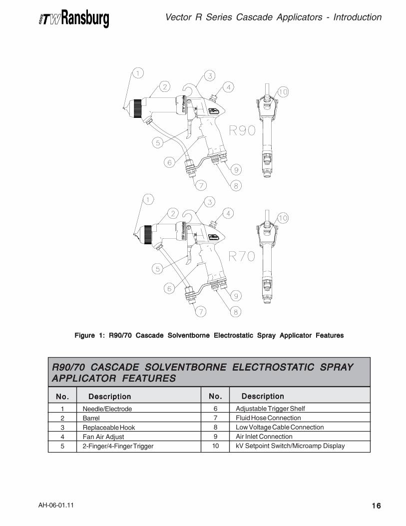
Figure 1: R90/70 Cascade Solventborne Electrostatic Spray Applicator FeaturesFigure 1: R90/70 Cascade Solventborne Electrostatic Spray Applicator FeaturesFigure 1: R90/70 Cascade Solventborne Electrostatic Spray Applicator FeaturesFigure 1: R90/70 Cascade Solventborne Electrostatic Spray Applicator FeaturesFigure 1: R90/70 Cascade Solventborne Electrostatic Spray Applicator Features
1
2
3
4
5
No.No.No.No.No. DescriptionDescriptionDescriptionDescriptionDescription
Needle/Electrode
Barrel
Replaceable Hook
Fan Air Adjust
2-Finger/4-Finger Trigger
R90/70 CASCADE SOLR90/70 CASCADE SOLR90/70 CASCADE SOLR90/70 CASCADE SOLR90/70 CASCADE SOLVENTBORNE ELECTROSTVENTBORNE ELECTROSTVENTBORNE ELECTROSTVENTBORNE ELECTROSTVENTBORNE ELECTROSTAAAAATIC SPRATIC SPRATIC SPRATIC SPRATIC SPRAYYYYYAPPLICAAPPLICAAPPLICAAPPLICAAPPLICATTTTTOR FEAOR FEAOR FEAOR FEAOR FEATURESTURESTURESTURESTURES
6
7
8
9
10
No.No.No.No.No. DescriptionDescriptionDescriptionDescriptionDescription
Adjustable Trigger Shelf
Fluid Hose Connection
Low Voltage Cable Connection
Air Inlet Connection
kV Setpoint Switch/Microamp Display
AH-06-01.11
Vector R Series Cascade Applicators - Introduction
1717171717
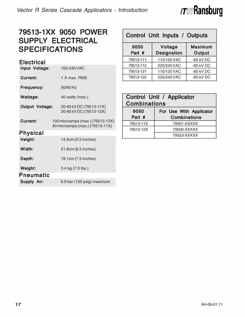
79513-1XX 9050 POWER79513-1XX 9050 POWER79513-1XX 9050 POWER79513-1XX 9050 POWER79513-1XX 9050 POWER
SUPPLSUPPLSUPPLSUPPLSUPPLYYYYY ELECTRICAL ELECTRICAL ELECTRICAL ELECTRICAL ELECTRICAL
SPECIFICASPECIFICASPECIFICASPECIFICASPECIFICATIONSTIONSTIONSTIONSTIONS
Input Voltage:Input Voltage:Input Voltage:Input Voltage:Input Voltage: 100-240 VAC
Current:Current:Current:Current:Current: 1 A max. RMS
Frequency:Frequency:Frequency:Frequency:Frequency: 50/60 Hz
Wattage:Wattage:Wattage:Wattage:Wattage: 40 watts (max.)
Output Voltage:Output Voltage:Output Voltage:Output Voltage:Output Voltage: 20-65 kV DC (79513-11X)20-85 kV DC (79513-12X)
Current:Current:Current:Current:Current: 100 microamps (max.) (79513-12X)90 microamps (max.) (79513-11X)
ElectricalElectricalElectricalElectricalElectrical
Height:Height:Height:Height:Height: 14.0cm (5.5-inches)
Width:Width:Width:Width:Width: 21.6cm (8.5-inches)
Depth:Depth:Depth:Depth:Depth: 19.1cm (7.5-inches)
Weight:Weight:Weight:Weight:Weight: 3.4 kg (7.5 lbs.)
PhysicalPhysicalPhysicalPhysicalPhysical
Supply Air:Supply Air:Supply Air:Supply Air:Supply Air: 6.9 bar (100 psig) maximum
PneumaticPneumaticPneumaticPneumaticPneumatic
110/120 VAC
220/240 VAC
110/120 VAC
220/240 VAC
79513-111
79513-112
79513-121
79513-122
-65 kV DC
-65 kV DC
-85 kV DC
-85 kV DC
VoltageVoltageVoltageVoltageVoltage
DesignationDesignationDesignationDesignationDesignation
MaximumMaximumMaximumMaximumMaximum
OutputOutputOutputOutputOutput
90509050905090509050
Part #Part #Part #Part #Part #
Control Unit Inputs / OutputsControl Unit Inputs / OutputsControl Unit Inputs / OutputsControl Unit Inputs / OutputsControl Unit Inputs / Outputs
79501-XXXXX
79500-XXXXX
79523-XXXXX
79513-11X
79513-12X
For Use With ApplicatorFor Use With ApplicatorFor Use With ApplicatorFor Use With ApplicatorFor Use With Applicator
CombinationsCombinationsCombinationsCombinationsCombinations
90509050905090509050
Part #Part #Part #Part #Part #
Control Unit / ApplicatorControl Unit / ApplicatorControl Unit / ApplicatorControl Unit / ApplicatorControl Unit / Applicator
CombinationsCombinationsCombinationsCombinationsCombinations
AH-06-01.11
Vector R Series Cascade Applicators - Introduction
1818181818
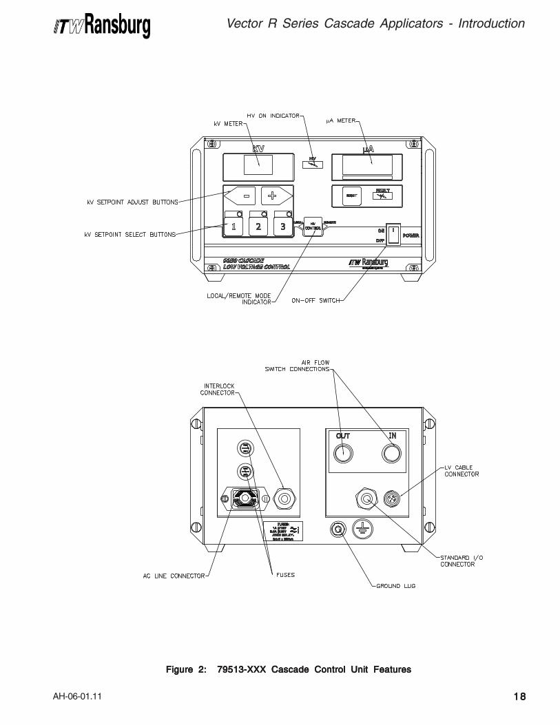
Figure 2: 79513-XXX Cascade Control Unit FeaturesFigure 2: 79513-XXX Cascade Control Unit FeaturesFigure 2: 79513-XXX Cascade Control Unit FeaturesFigure 2: 79513-XXX Cascade Control Unit FeaturesFigure 2: 79513-XXX Cascade Control Unit Features
AH-06-01.11
INSTINSTINSTINSTINSTALLAALLAALLAALLAALLATIONTIONTIONTIONTION
79500 R90 SOL79500 R90 SOL79500 R90 SOL79500 R90 SOL79500 R90 SOLVENTBORNEVENTBORNEVENTBORNEVENTBORNEVENTBORNE
79501 R70 SOL79501 R70 SOL79501 R70 SOL79501 R70 SOL79501 R70 SOLVENTBORNEVENTBORNEVENTBORNEVENTBORNEVENTBORNE
INSTINSTINSTINSTINSTALLAALLAALLAALLAALLATIONTIONTIONTIONTION
>The control unit MUSTMUSTMUSTMUSTMUST be located
outside of the spray area.
> The User MUSTMUSTMUSTMUSTMUST read and be familiar
with the "Safety" section of thismanual.
> This manual MUSTMUSTMUSTMUSTMUST be read and thor-oughly understood by ALLALLALLALLALL personnel whooperate, clean, or maintain this equipment!Special care should be taken to ensure thatthe warnings and requirements for operatingand servicing safety are followed. The usershould be awre of and adhere to ALLALLALLALLALL localbuilding and fire codes and ordinances aswell as NFPA, OSHA, and all related coun-try safety codes prior to installing, operating,and/or servicing this eqiupment.
> The fluid lines and fluid sources MUSTMUSTMUSTMUSTMUSTbe isolated from ground for waterbaseapplications.
> Personnel MUST MUST MUST MUST MUST be GROUNDEDGROUNDEDGROUNDEDGROUNDEDGROUNDED toprevent a shock or spark during electro-static operation.
> Install and route the hoses and cable sothey are NOTNOTNOTNOTNOT exposed to temperatures in
excess of 120° F and so that all hose and
cable bends are NO LESSNO LESSNO LESSNO LESSNO LESS than a 6 inch(15cm) radius. Failure to comply with theseparameters cold cause equipment malfunc-tion that might create HAZARDOUSHAZARDOUSHAZARDOUSHAZARDOUSHAZARDOUS
CONDITIONS!CONDITIONS!CONDITIONS!CONDITIONS!CONDITIONS!
> Install only one spray applicator perisolated waterborne fluid supply system.
W A R N I N GW A R N I N GW A R N I N GW A R N I N GW A R N I N G!!!!!
Vector R Series Cascade Applicators - Installation
1919191919
>NEVERNEVERNEVERNEVERNEVER wrap the applicator, associated
valves and tubing, and supporting hardwarein plastic to keep it clean. A surface chargemay build up on the plastic surface anddischarge to the nearest grounded object.Efficiency of the applicator will also bereduced and damage or failure of the appli-cator components may occur. WRAP-WRAP-WRAP-WRAP-WRAP-
PING THE APPLICATOR IN PLASTICPING THE APPLICATOR IN PLASTICPING THE APPLICATOR IN PLASTICPING THE APPLICATOR IN PLASTICPING THE APPLICATOR IN PLASTIC
WILL VOID WARRANTY. WILL VOID WARRANTY. WILL VOID WARRANTY. WILL VOID WARRANTY. WILL VOID WARRANTY. Only ap-proved applicator covers should be used.
W A R N I N GW A R N I N GW A R N I N GW A R N I N GW A R N I N G!!!!!
TYPICALTYPICALTYPICALTYPICALTYPICAL
SOLSOLSOLSOLSOLVENTBORNEVENTBORNEVENTBORNEVENTBORNEVENTBORNE
INSTINSTINSTINSTINSTALLAALLAALLAALLAALLATIONTIONTIONTIONTION(See "Figure 3 - T(See "Figure 3 - T(See "Figure 3 - T(See "Figure 3 - T(See "Figure 3 - Typicalypicalypicalypicalypical
Solventborne InstallationSolventborne InstallationSolventborne InstallationSolventborne InstallationSolventborne Installation
Features")Features")Features")Features")Features")
Location of Control UnitLocation of Control UnitLocation of Control UnitLocation of Control UnitLocation of Control UnitInstall the low voltage control unit in an area
outside the hazardous locationoutside the hazardous locationoutside the hazardous locationoutside the hazardous locationoutside the hazardous location in accordancewith federal, state, and local codes. The areashould protect the control unit from the possibilityof environmental intrusion (such as dust ormoisture), have ambient temperatures that do notexceed 120°F, and be as close to the applicator aspossible to minimize the length of low voltagecable.
AH-06-01.11
Vector R Series Cascade Applicators - Installation
2020202020
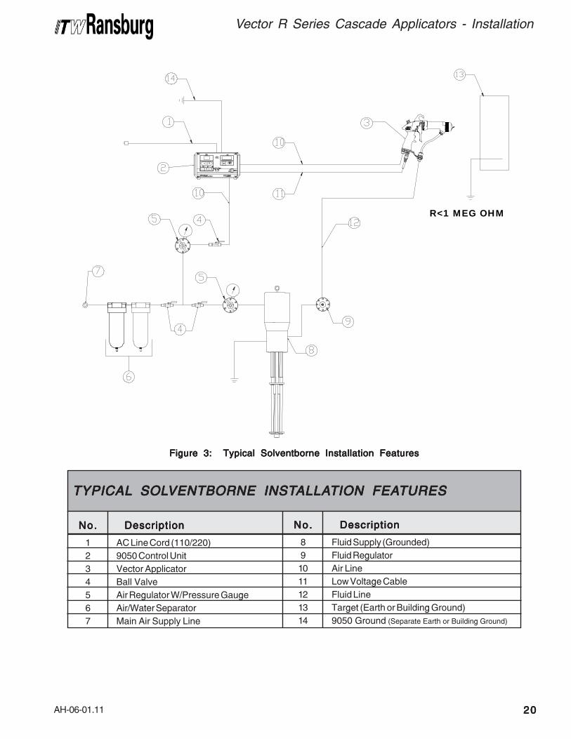
Figure 3: Typical Solventborne Installation FeaturesFigure 3: Typical Solventborne Installation FeaturesFigure 3: Typical Solventborne Installation FeaturesFigure 3: Typical Solventborne Installation FeaturesFigure 3: Typical Solventborne Installation Features
R<1 MEG OHM
1
2
3
4
5
6
7
No.No.No.No.No. DescriptionDescriptionDescriptionDescriptionDescription
AC Line Cord (110/220)
9050 Control Unit
Vector Applicator
Ball Valve
Air Regulator W/Pressure Gauge
Air/Water Separator
Main Air Supply Line
TYPICALTYPICALTYPICALTYPICALTYPICAL SOL SOL SOL SOL SOLVENTBORNE INSTVENTBORNE INSTVENTBORNE INSTVENTBORNE INSTVENTBORNE INSTALLAALLAALLAALLAALLATION FEATION FEATION FEATION FEATION FEATURESTURESTURESTURESTURES
8
9
10
11
12
13
14
No.No.No.No.No. DescriptionDescriptionDescriptionDescriptionDescription
Fluid Supply (Grounded)
Fluid Regulator
Air Line
Low Voltage Cable
Fluid Line
Target (Earth or Building Ground)
9050 Ground (Separate Earth or Building Ground)
AH-06-01.11
Vector R Series Cascade Applicators - Installation
2121212121
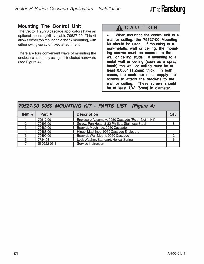
> When mounting the control unit to aWhen mounting the control unit to aWhen mounting the control unit to aWhen mounting the control unit to aWhen mounting the control unit to a
wall or ceiling, the 79527-00 Mountingwall or ceiling, the 79527-00 Mountingwall or ceiling, the 79527-00 Mountingwall or ceiling, the 79527-00 Mountingwall or ceiling, the 79527-00 Mounting
Kit should be used. If mounting to aKit should be used. If mounting to aKit should be used. If mounting to aKit should be used. If mounting to aKit should be used. If mounting to a
non-metallic wall or ceiling, the mount-non-metallic wall or ceiling, the mount-non-metallic wall or ceiling, the mount-non-metallic wall or ceiling, the mount-non-metallic wall or ceiling, the mount-
ing screws must be secured to theing screws must be secured to theing screws must be secured to theing screws must be secured to theing screws must be secured to the
wall or ceiling studs. If mounting to awall or ceiling studs. If mounting to awall or ceiling studs. If mounting to awall or ceiling studs. If mounting to awall or ceiling studs. If mounting to a
metal wall or ceiling (such as a spraymetal wall or ceiling (such as a spraymetal wall or ceiling (such as a spraymetal wall or ceiling (such as a spraymetal wall or ceiling (such as a spray
booth) the wall or ceiling must be atbooth) the wall or ceiling must be atbooth) the wall or ceiling must be atbooth) the wall or ceiling must be atbooth) the wall or ceiling must be at
least 0.050" (1.2mm) thick. In bothleast 0.050" (1.2mm) thick. In bothleast 0.050" (1.2mm) thick. In bothleast 0.050" (1.2mm) thick. In bothleast 0.050" (1.2mm) thick. In both
cases, the customer must supply thecases, the customer must supply thecases, the customer must supply thecases, the customer must supply thecases, the customer must supply the
screws to attach the brackets to thescrews to attach the brackets to thescrews to attach the brackets to thescrews to attach the brackets to thescrews to attach the brackets to the
wall or ceiling. These screws shouldwall or ceiling. These screws shouldwall or ceiling. These screws shouldwall or ceiling. These screws shouldwall or ceiling. These screws should
be at least 1/4" (6mm) in diameter.be at least 1/4" (6mm) in diameter.be at least 1/4" (6mm) in diameter.be at least 1/4" (6mm) in diameter.be at least 1/4" (6mm) in diameter.
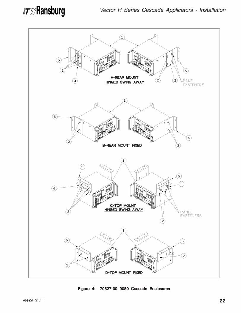
C A U T I O NC A U T I O NC A U T I O NC A U T I O NC A U T I O N!!!!!Mounting The Control UnitMounting The Control UnitMounting The Control UnitMounting The Control UnitMounting The Control UnitThe Vector R90/70 cascade applicators have anoptional mounting kit available 79527-00. This kitallows either top mounting or back mounting, witheither swing-away or fixed attachment.
There are four convenient ways of mounting theenclosure assembly using the included hardware(see Figure 4).
1 79512-00 Enclosure Assembly, 9050 Cascade (Ref. - Not in Kit) --2 79493-00 Screw, Pan Head, 8-32 Phillips, Stainless Steel 83 79489-00 Bracket, Machined, 9050 Cascade 14 79488-00 Hinge, Machined, 9050 Cascade Enclosure 15 79490-00 Bracket, Wall Mount, 9050 Cascade 26 7734-03 Lock Washer, Standard, Helical Spring 67 SI-0222-06.1 Service Instruction 1
Item #Item #Item #Item #Item #
79527-00 9050 MOUNTING KIT79527-00 9050 MOUNTING KIT79527-00 9050 MOUNTING KIT79527-00 9050 MOUNTING KIT79527-00 9050 MOUNTING KIT - P - P - P - P - PARARARARARTS LISTTS LISTTS LISTTS LISTTS LIST (Figure 4) (Figure 4) (Figure 4) (Figure 4) (Figure 4)
Part #Part #Part #Part #Part # DescriptionDescriptionDescriptionDescriptionDescription Q t yQ t yQ t yQ t yQ t y
AH-06-01.11
Vector R Series Cascade Applicators - Installation
2222222222
Figure 4: 79527-00 9050 Cascade EnclosuresFigure 4: 79527-00 9050 Cascade EnclosuresFigure 4: 79527-00 9050 Cascade EnclosuresFigure 4: 79527-00 9050 Cascade EnclosuresFigure 4: 79527-00 9050 Cascade Enclosures
5
2
4
5
2
5
32
5
2
1
1
1
1
2
5
2
3
5
2
5
2
4
5
AH-06-01.11
Vector R Series Cascade Applicators - Installation
2323232323
ELECTRICAL NOISEELECTRICAL NOISEELECTRICAL NOISEELECTRICAL NOISEELECTRICAL NOISE
Electrical noise refers to stray electrical signals inthe atmosphere at various signal strengths andfrequencies that can affect the operation ofequipment. One of the best ways to prevent thisis to shield the equipment and cables within a
continuouscontinuouscontinuouscontinuouscontinuous ground envelope, such that anyincident noise will be conducted to earth groundbefore it can affect the circuit conductors.
For conductors inside the control unit or powersupply, the grounded enclosures provide thisenvelope. For the cables that connect the applicatorto the control unit or power supply, a shieldedcable has been used. The shield consists of anoverall foil shield in combination with an overallbraided shield. This provides the most effectiveshielding, as the foil covers the “holes” in the braid,and the braid allows for practical 360° terminationat both ends of the cable.
The AC input cord is not shielded, but instead isdirected to an AC line filter as soon as it enters thecabinet. This method filters out any noise thatcomes in on the AC line. For maximum noiseimmunity the AC line should connect to the filter assoon as it enters the cabinet with as short of leadsas possible. Additional noise protection can beprovided by running the AC input line to the controlpanel in grounded conduit.
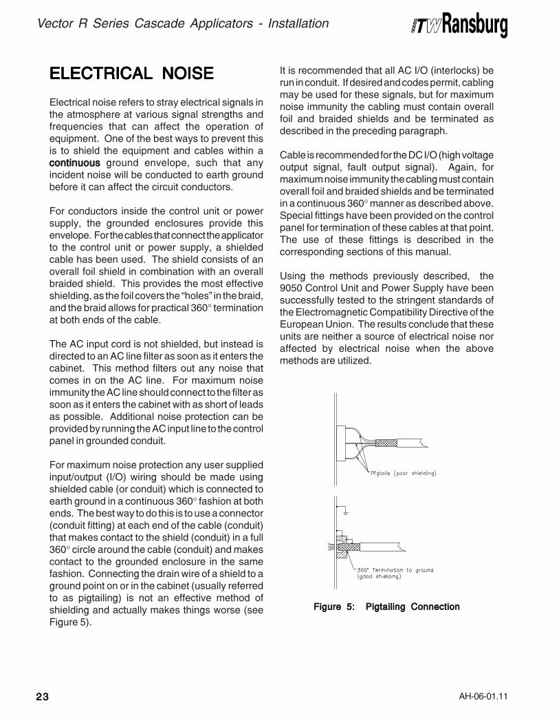
For maximum noise protection any user suppliedinput/output (I/O) wiring should be made usingshielded cable (or conduit) which is connected toearth ground in a continuous 360° fashion at bothends. The best way to do this is to use a connector(conduit fitting) at each end of the cable (conduit)that makes contact to the shield (conduit) in a full360° circle around the cable (conduit) and makescontact to the grounded enclosure in the samefashion. Connecting the drain wire of a shield to aground point on or in the cabinet (usually referredto as pigtailing) is not an effective method ofshielding and actually makes things worse (seeFigure 5).
It is recommended that all AC I/O (interlocks) berun in conduit. If desired and codes permit, cablingmay be used for these signals, but for maximumnoise immunity the cabling must contain overallfoil and braided shields and be terminated asdescribed in the preceding paragraph.
Cable is recommended for the DC I/O (high voltageoutput signal, fault output signal). Again, formaximum noise immunity the cabling must containoverall foil and braided shields and be terminatedin a continuous 360° manner as described above.Special fittings have been provided on the controlpanel for termination of these cables at that point.The use of these fittings is described in thecorresponding sections of this manual.
Using the methods previously described, the9050 Control Unit and Power Supply have beensuccessfully tested to the stringent standards ofthe Electromagnetic Compatibility Directive of theEuropean Union. The results conclude that theseunits are neither a source of electrical noise noraffected by electrical noise when the abovemethods are utilized.
Figure 5: Pigtailing ConnectionFigure 5: Pigtailing ConnectionFigure 5: Pigtailing ConnectionFigure 5: Pigtailing ConnectionFigure 5: Pigtailing Connection
AH-06-01.11
Vector R Series Cascade Applicators - Installation
2424242424
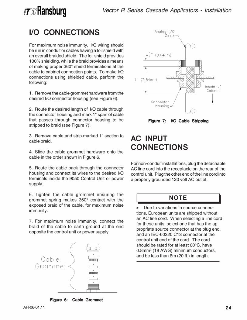
I/O CONNECTIONSI/O CONNECTIONSI/O CONNECTIONSI/O CONNECTIONSI/O CONNECTIONS
For maximum noise immunity, I/O wiring shouldbe run in conduit or cables having a foil shield withan overall braided shield. The foil shield provides100% shielding, while the braid provides a meansof making proper 360° shield terminations at thecable to cabinet connection points. To make I/Oconnections using shielded cable, perform thefollowing:
1. Remove the cable grommet hardware from thedesired I/O connector housing (see Figure 6).
2. Route the desired length of I/O cable throughthe connector housing and mark 1" span of cablethat passes through connector housing to bestripped to braid (see Figure 7).
3. Remove cable and strip marked 1" section tocable braid.
4. Slide the cable grommet hardware onto thecable in the order shown in Figure 6.
5. Route the cable back through the connectorhousing and connect its wires to the desired I/Oterminals inside the 9050 Control Unit or powersupply.
6. Tighten the cable grommet ensuring thegrommet spring makes 360° contact with theexposed braid of the cable, for maximum noiseimmunity.
7. For maximum noise immunity, connect thebraid of the cable to earth ground at the endopposite the control unit or power supply.
Figure 7: I/O Cable StrippingFigure 7: I/O Cable StrippingFigure 7: I/O Cable StrippingFigure 7: I/O Cable StrippingFigure 7: I/O Cable Stripping
Figure 6: Cable GrommetFigure 6: Cable GrommetFigure 6: Cable GrommetFigure 6: Cable GrommetFigure 6: Cable Grommet
AC INPUTAC INPUTAC INPUTAC INPUTAC INPUT
CONNECTIONSCONNECTIONSCONNECTIONSCONNECTIONSCONNECTIONS
For non-conduit installations, plug the detachableAC line cord into the receptacle on the rear of thecontrol unit. Plug the other end of the line cord intoa properly grounded 120 volt AC outlet.
>Due to variations in source connec-
tions, European units are shipped withoutan AC line cord. When selecting a line cordfor these units, select one that has the ap-propriate source connector at the plug end,and an IEC-60320 C13 connector at thecontrol unit end of the cord. The cordshould be rated for at least 60°C, have0.8mm2 (18 AWG) minimum conductors,and be less than 6m (20 ft.) in length.
NOTENOTENOTENOTENOTE
AH-06-01.11
Vector R Series Cascade Applicators - Installation
2525252525
INTERLOCKSINTERLOCKSINTERLOCKSINTERLOCKSINTERLOCKS
Interlocks required by code are as follows:
• Booth Fan Interlock - When the booth fan is on,a contact closure is made.
• Conveyor Interlock - when the conveyor ismoving a contact closure is made.
• Solvent Interlock - When solvent supply to theapplicator is off, a contact closure is made.
>In general, conduit must be used for ap-
proved AC installation, however, if nationaland local codes permit, the AC power maybe supplied via the factory supplied linecord. If conduit is utilized, the control unitAC input wiring may be routed through anoptional explosion proof switch mounted onor near the spray booth where it will be con-venient to the operator.
NOTENOTENOTENOTENOTE
For installations where it is required to run the ACinput wiring in conduit, perform the following:
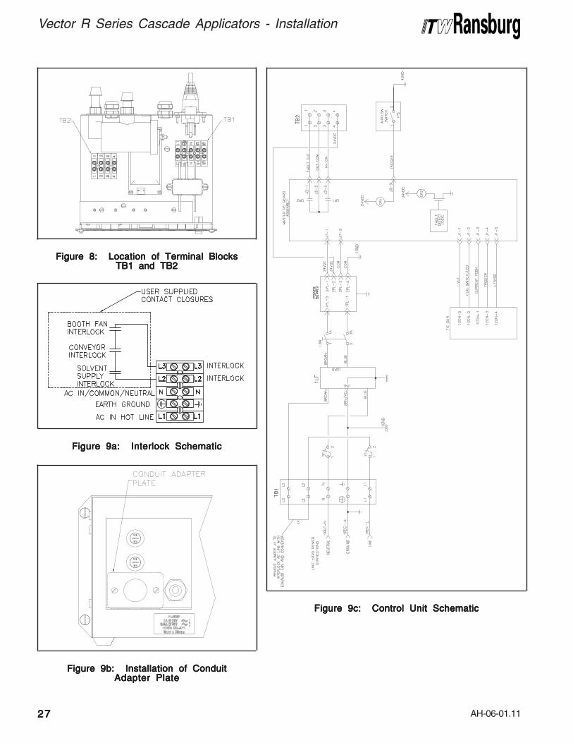
1. Ensure the AC line cord is unpluggedEnsure the AC line cord is unpluggedEnsure the AC line cord is unpluggedEnsure the AC line cord is unpluggedEnsure the AC line cord is unplugged andremove the AC inlet receptacle wiring from TB1-N,TB1- L1 and TB1-EARTH GROUND (see Figures8 and 9a).
2. Remove the mounting hardware from the ACinlet receptacle and remove it from the rear of thecontrol unit.
3. Install the Conduit Adapter Plate (supplied) inthe hole where the AC inlet receptacle was removed(see Figure 9b).
4. Install the AC input wiring (0.8mm2 (18 AWG)minimum) through the Conduit Adapter Plate usingconduit and wire to TB1 as follows:
Hot/Line to TB1-L1 Neutral/Common to TB1-N Ground to TB1-EARTH GROUND
>When using conduit to route the AC in-
put wiring to the control unit, the last severalfeet of conduit attached to the control unitshould be of a flexible type, such that thecontrol unit chassis can still be slid out of itsenclosure for testing and set-up purposes.
NOTENOTENOTENOTENOTE
Safety GroundSafety GroundSafety GroundSafety GroundSafety GroundCrimp the appropriate terminal onto the groundwire assembly and install from the control unitground lug, located on the back of the control unit,to a true earth ground.
>Failure to connect interlocks could result
in fire or explosion.
W A R N I N GW A R N I N GW A R N I N GW A R N I N GW A R N I N G!!!!!
>ALWAYSALWAYSALWAYSALWAYSALWAYS ensure that high voltage is
OFFOFFOFFOFFOFF before flushing the spray applicatorwith solvent. NEVERNEVERNEVERNEVERNEVER flush the sprayapplicator with high voltage ONONONONON, as this is asevere fire hazard and risk to personnelsafety. It is recommended that the highvoltage control be interlocked with thesolvent flush signal so that high voltage isautomatically locked out whenever flushingoccurs. Consult your authorized ITWRansburg representative for information oninterlocking the high voltage OFF OFF OFF OFF OFF signalwith the solvent flush signal.
W A R N I N GW A R N I N GW A R N I N GW A R N I N GW A R N I N G!!!!!
AH-06-01.11
Vector R Series Cascade Applicators - Installation
2626262626
To install the control unit interlocks perform thefollowing:
1. Turn the control unit off and remove theTurn the control unit off and remove theTurn the control unit off and remove theTurn the control unit off and remove theTurn the control unit off and remove the
fuses.fuses.fuses.fuses.fuses.
2. Loosen the front panel screws and slide thecontrol unit chassis out.
3. Using a small blade screwdriver, remove thefactory installed test jumper from TB1-L2 to TB1-L3.
4. Using a shielded cable for the interlock wiring(supplied by user), route through the interlockconnector on the rear of the control unit andterminate to TB1-L2 and TB1-L3 as shown inFigure 9a. The shielded cable must have aminimum rating of 300V and 105°C and itsconductors should be 0.8mm2 (18 AWG) minimum.Secure the cable to the interlock connector asdescribed in the "I/O Connectors" in the"Installation" section, so that the shield of the cableis connected to the chassis of the enclosure.
>Some codes may require the interlock
wiring to be run in conduit. In this caseshielded cable is not necessary, but theconductors used should still meet the rat-ings specified above.
NOTENOTENOTENOTENOTE
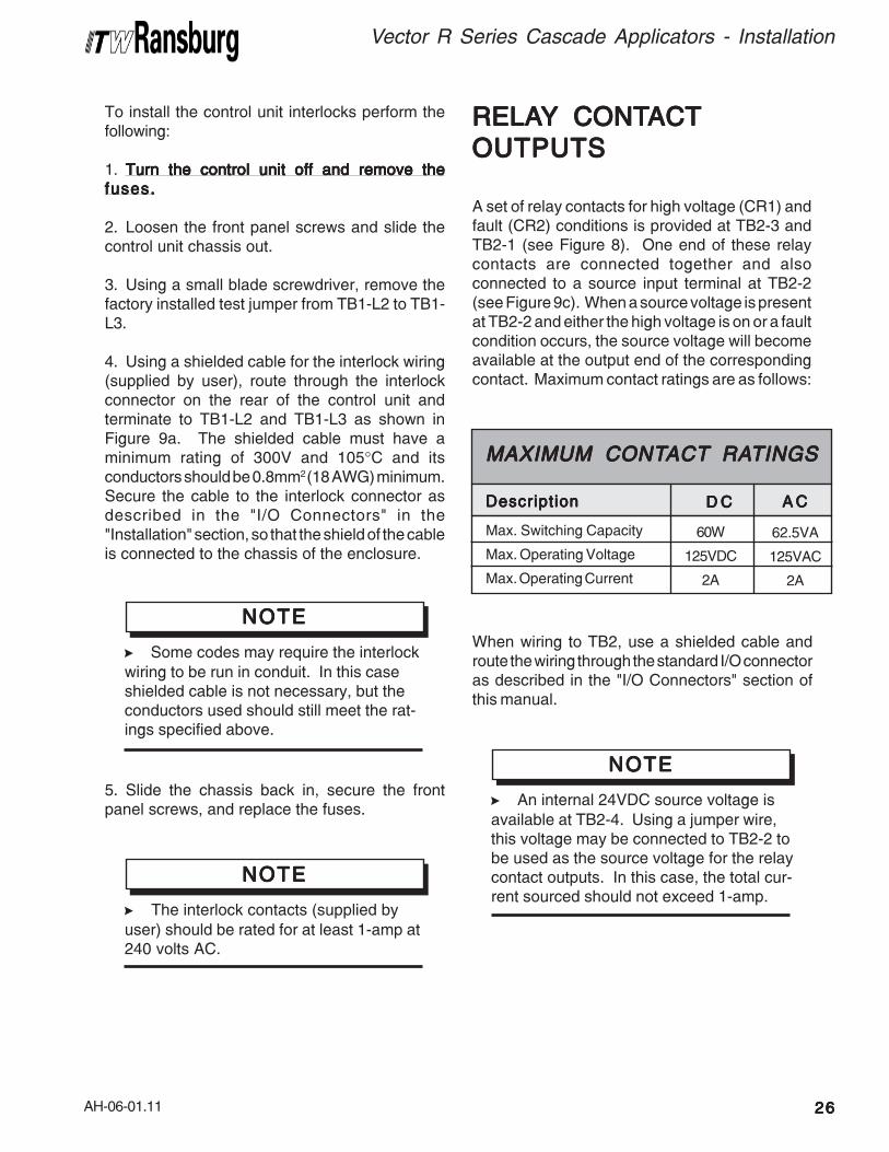
RELARELARELARELARELAYYYYY CONT CONT CONT CONT CONTACTACTACTACTACT
OUTPUTSOUTPUTSOUTPUTSOUTPUTSOUTPUTS
A set of relay contacts for high voltage (CR1) andfault (CR2) conditions is provided at TB2-3 andTB2-1 (see Figure 8). One end of these relaycontacts are connected together and alsoconnected to a source input terminal at TB2-2(see Figure 9c). When a source voltage is presentat TB2-2 and either the high voltage is on or a faultcondition occurs, the source voltage will becomeavailable at the output end of the correspondingcontact. Maximum contact ratings are as follows:
>The interlock contacts (supplied by
user) should be rated for at least 1-amp at240 volts AC.
NOTENOTENOTENOTENOTE
Max. Switching Capacity
Max. Operating Voltage
Max. Operating Current
MAXIMUM CONTMAXIMUM CONTMAXIMUM CONTMAXIMUM CONTMAXIMUM CONTACTACTACTACTACT RA RA RA RA RATINGSTINGSTINGSTINGSTINGS
62.5VA
125VAC
2A
A CA CA CA CA CDescriptionDescriptionDescriptionDescriptionDescription
60W
125VDC
2A
D CD CD CD CD C
When wiring to TB2, use a shielded cable androute the wiring through the standard I/O connectoras described in the "I/O Connectors" section ofthis manual.
>An internal 24VDC source voltage is
available at TB2-4. Using a jumper wire,this voltage may be connected to TB2-2 tobe used as the source voltage for the relaycontact outputs. In this case, the total cur-rent sourced should not exceed 1-amp.
NOTENOTENOTENOTENOTE5. Slide the chassis back in, secure the frontpanel screws, and replace the fuses.
AH-06-01.11
Vector R Series Cascade Applicators - Installation
2727272727
Figure 8: Location of Terminal BlocksFigure 8: Location of Terminal BlocksFigure 8: Location of Terminal BlocksFigure 8: Location of Terminal BlocksFigure 8: Location of Terminal BlocksTB1 and TB2TB1 and TB2TB1 and TB2TB1 and TB2TB1 and TB2
Figure 9a: Interlock SchematicFigure 9a: Interlock SchematicFigure 9a: Interlock SchematicFigure 9a: Interlock SchematicFigure 9a: Interlock Schematic
Figure 9b: Installation of ConduitFigure 9b: Installation of ConduitFigure 9b: Installation of ConduitFigure 9b: Installation of ConduitFigure 9b: Installation of ConduitAdapter PlateAdapter PlateAdapter PlateAdapter PlateAdapter Plate
Figure 9c: Control Unit SchematicFigure 9c: Control Unit SchematicFigure 9c: Control Unit SchematicFigure 9c: Control Unit SchematicFigure 9c: Control Unit Schematic

AH-06-01.11
Vector R Series Cascade Applicators - Installation
2828282828
FILFILFILFILFILTERSTERSTERSTERSTERS
1. Install an air filter assembly on the air inlet of thecontrol unit. The filter should be 5 micron with amaximum working pressure of at least 100 psig(6.9 bar). Screw the fitting into the filter inlet. Thefilter MUST be installed with the arrow pointing inthe direction of flow. (Refer to the appropriateFilter Assembly manual for "Installation Instruc-tions".)
When the applicator is triggered, the resulting airflow closes the contacts of the air flow switch,thereby activating high voltage at the applicator.
2. ITW Ransburg recommends that a fluid filter beinstalled at the output of the fluid supply (pressurepot, pump, circulating system, etc.). It is the enduser's responsibility to install the proper filter thatmeets their system's requirements.
LOW VOLLOW VOLLOW VOLLOW VOLLOW VOLTTTTTAGE CABLEAGE CABLEAGE CABLEAGE CABLEAGE CABLE
Connect the low voltage cable from the control unitto the applicator using a wrench to tighten.
Figure 10: Daisy Chained CableFigure 10: Daisy Chained CableFigure 10: Daisy Chained CableFigure 10: Daisy Chained CableFigure 10: Daisy Chained Cable
>DO NOT DO NOT DO NOT DO NOT DO NOT overtighten the low voltage
connection at the applicator. The plasticparts could be damaged.
C A U T I O NC A U T I O NC A U T I O NC A U T I O NC A U T I O N!!!!!
With the Vector design, multiple cables may beconnected together to create the length required,up to a maximum of 30m (100 ft.). To connect thecables, insert the male end of one cable into thefemale end of the other. Tighten both cableconnectors against each other using two (2) 16mm(5/8") open-end wrenches.
>The electrical discharge that is available
from the charging electrode must not exceed0.25 mJ of energy. To achieve this limit, anyflow of energy from the paint supply throughthe paint line to the applicator electrode mustbe prevented by grounding the paint line atthe applicator handle.
Verify that the applicator handle is actuallygrounded before operating it! This is donewith a fully connected and operationalsystem, by placing one lead of an ohmmeterto the handle and the other to the buildingelectrical ground (cold water pipe, buildingstructure, steel, etc.). This reading shouldbe essentially zero.
If a greater reading is obtained, check thatthe control unit is grounded. (See thecontrol unit manual for "Grounding Proce-dure.")
W A R N I N GW A R N I N GW A R N I N GW A R N I N GW A R N I N G!!!!!
>An air filter MUSTMUSTMUSTMUSTMUST be installed to permit
proper functioning of the air flow switchinside the control unit. This unit must filterparticles 5 microns and larger.
C A U T I O NC A U T I O NC A U T I O NC A U T I O NC A U T I O N!!!!!
>Class 3 air quality is recommended.
Class 3 air quality has a maximum 5 micronparticle size, a dew point of -4°F (-20°C),and a relative humidity of 5%.
NOTENOTENOTENOTENOTE
AH-06-01.11
Vector R Series Cascade Applicators - Installation
2929292929
Routing of Air and Fluid HosesRouting of Air and Fluid HosesRouting of Air and Fluid HosesRouting of Air and Fluid HosesRouting of Air and Fluid HosesStarting at the applicator, route the air hose alongthe same path as the low voltage cable to the lowvoltage control unit. The fluid hose can be run withthe low voltage cable and air hose or it can beseparate and run to the fluid source. Do notexpose the hoses to high temperatures (over120°F) and/or conditions such as moving parts,foot traffic, vehicle traffic, etc.
Prior to connecting the air hose to the low voltageunit and the fluid hose to the fluid supply, adjust thehose and low voltage cable position at the applicatorto relieve some strain on the low voltage cable. Todo this, perform the following procedure:
1. Disconnect the air hose from the applicator.
2. Position the air hose 1-inch (2.5cm) away fromthe bottom of the handle.
3. Secure the air hose to the low voltage cable.Secure the two together at one additional location,about 12-16-inches (30-41cm) back.
4. With a wrench, reconnect and secure the airhose to the applicator. (This should form a smallloop in the low voltage cable.)
5. Secure the fluid hose to the air hose and lowvoltage cable as needed.
Adjust the length of the air hose to the low voltagecontroller and install the fitting to the hose.
Air Hose RecommendationAir Hose RecommendationAir Hose RecommendationAir Hose RecommendationAir Hose RecommendationITW Ransburg recommends using a 79547-XX airhose assembly that may be ordered through yourauthorized ITW Ransburg distributor. This hoseperforms best with the Vector to reduce air hosestiffness along with weight reduction. Availablehose lengths are listed in "Accessories" in the"Parts Identification" section of this manual.
Fluid Hose RecommendationFluid Hose RecommendationFluid Hose RecommendationFluid Hose RecommendationFluid Hose RecommendationITW Ransburg recommends using a 79548 fluidhose assembly. This assembly is made tospecifically fit the fluid fitting size engineered intothe applicator. This hose is available from yourauthorized ITW Ransburg distributor. Availablehose lengths are listed in "Accessories" in the"Parts Identification" section of this manual.
>Any user installed air hose must be
rated for 100 psig (6.9 bar) working pres-sure minimum.
C A U T I O NC A U T I O NC A U T I O NC A U T I O NC A U T I O N!!!!!
Air and Fluid Hose InstallationAir and Fluid Hose InstallationAir and Fluid Hose InstallationAir and Fluid Hose InstallationAir and Fluid Hose InstallationThe fluid inlet fitting for the Vector applicator is3/8-18 NPSM(M). When installing a fluid hose,tighten the fitting adequately to prevent any fluidleaks. The air inlet fitting is 1/4-18 NPSM(M).When installing the air hose, use a wrench to holdthe air inlet fitting on the Vector and tighten the airhose fitting enough to prevent any air leaks.
>Any user installed fluid hose used must
be rated for 100 psig (6.9 bar) workingpressure minimum.
C A U T I O NC A U T I O NC A U T I O NC A U T I O NC A U T I O N!!!!!
>When securing the air hose, fluid hose,
and low voltage cable together, take carenot to use items such as wire or anythingthat might cut into the hoses or cable. If wireties are used, they should only be tightenough to secure the cable and not so tightthat they might restrict fluid and air flow.
W A R N I N GW A R N I N GW A R N I N GW A R N I N GW A R N I N G!!!!!
AH-06-01.11
Vector R Series Cascade Applicators - Installation
3030303030
PPPPPAINTAINTAINTAINTAINT PREP PREP PREP PREP PREPARAARAARAARAARATIONTIONTIONTIONTION
A proper paint mixture is essential to electrostaticoperation. Paint test equipment may be obtainedthrough your ITW Ransburg distributor. Referencethe Technical Manual "Paint Related Informationfor REA, REM, Vector, and M90 Guns" for paintformulation information. For further paintformulation and testing procedures, consult yourITW Ransburg distributor and/or your paintsupplier.
SPRASPRASPRASPRASPRAYYYYY P P P P PAAAAATTERNTTERNTTERNTTERNTTERN
ADJUSTMENTADJUSTMENTADJUSTMENTADJUSTMENTADJUSTMENT
The spray pattern of fan atomizers is adjustablefrom a small circle to an elongated oval,approximately 10-18-inches of usable pattern whensprayed from a target distance of 8-12-inches.The swirl atomizer assemblies produce a roundpattern from 4-6-inches in diameter. The fancontrol knob provides control of the pattern shapingair. Counter-clockwise expands the pattern andclockwise reduces it.
The Vector has a distinct feature that allowscounting of clicks. The fan valve has 8 clicks per1 full turn of the adjustment knob.
To change the spray pattern axis of fan atomizersfrom horizontal to vertical, loosen the air nozzleretaining ring, rotate the air cap clockwise to thedesired position, and gently tighten the ring.
>See the ITW Ransburg bulletin "Hand-
gun Spray Techniques".
NOTENOTENOTENOTENOTE
APPLICAAPPLICAAPPLICAAPPLICAAPPLICATTTTTOR TOR TOR TOR TOR TOOOOO
TTTTTARGETARGETARGETARGETARGET DIST DIST DIST DIST DISTANCEANCEANCEANCEANCE
Hold the applicator 6-12-inches maximum fromthe target for best operation (higher transferefficiency will be achieved at the closer targetdistance). Trigger the applicator fully to operate.

AH-06-01.11
Vector R Series Cascade Applicators - Installation
3131313131
79374-65
79374-65
79374-98
79374-98
79374-122
79374-122
Air CapAir CapAir CapAir CapAir CapPart #Part #Part #Part #Part # Orifice IDOrifice IDOrifice IDOrifice IDOrifice ID
Fluid NozzleFluid NozzleFluid NozzleFluid NozzleFluid NozzlePart #Part #Part #Part #Part #
79377-44
79377-45
79377-44
79377-45
79552-44
79552-45
AIR CAP / FLUID NOZZLE SELECTION CHARTAIR CAP / FLUID NOZZLE SELECTION CHARTAIR CAP / FLUID NOZZLE SELECTION CHARTAIR CAP / FLUID NOZZLE SELECTION CHARTAIR CAP / FLUID NOZZLE SELECTION CHARTAir Spray / TAir Spray / TAir Spray / TAir Spray / TAir Spray / Trans-Trans-Trans-Trans-Trans-Tech. Sprayech. Sprayech. Sprayech. Sprayech. Spray
SeparateSeparateSeparateSeparateSeparateRetaining RingRetaining RingRetaining RingRetaining RingRetaining Ring
PressurePressurePressurePressurePressureReducerReducerReducerReducerReducer
1.4mm (.055)
1.8mm (.070)
1.4mm (.055)
1.8mm (.070)
1.4mm (.055)
1.8mm (.070)
79379-00
79379-00
79379-00
79379-00
79379-00
79379-00
74963-05
74963-05
74963-05
74963-05
74963-06
74963-06
Orifice IDOrifice IDOrifice IDOrifice IDOrifice IDFluid NozzleFluid NozzleFluid NozzleFluid NozzleFluid Nozzle
Part #Part #Part #Part #Part #
79377-44
79377-144
79377-45
79377-145
79377-46
79377-146
79377-47
79377-147
79377-48
79377-148
FLUID NOZZLE SELECTIONFLUID NOZZLE SELECTIONFLUID NOZZLE SELECTIONFLUID NOZZLE SELECTIONFLUID NOZZLE SELECTIONSTD SPRASTD SPRASTD SPRASTD SPRASTD SPRAYYYYY CHAR CHAR CHAR CHAR CHARTTTTT
Nozzle MaterialNozzle MaterialNozzle MaterialNozzle MaterialNozzle Material
1.4mm (.055 inch)
1.4mm (.055 inch)
1.8mm (.070 inch)
1.8mm (.070 inch)
1.0mm (.042 inch)
1.0mm (.042 inch)
.7mm (.028 inch)
.7mm (.028 inch)
1.2mm (.047 inch)
1.2mm (.047 inch)
Standard Wear
Extended Wear
Standard Wear
Extended Wear
Standard Wear
Extended Wear
Standard Wear
Extended Wear
Standard Wear
Extended Wear
Orifice IDOrifice IDOrifice IDOrifice IDOrifice IDFluid NozzleFluid NozzleFluid NozzleFluid NozzleFluid Nozzle
Part #Part #Part #Part #Part #
79552-244
79552-344
79552-245
79552-345
79552-246
79552-346
79552-247
79552-347
79552-248
79552-348
FLUID NOZZLE SELECTIONFLUID NOZZLE SELECTIONFLUID NOZZLE SELECTIONFLUID NOZZLE SELECTIONFLUID NOZZLE SELECTIONTRANS-TECH. CHARTTRANS-TECH. CHARTTRANS-TECH. CHARTTRANS-TECH. CHARTTRANS-TECH. CHART
Nozzle MaterialNozzle MaterialNozzle MaterialNozzle MaterialNozzle Material
1.4mm (.055 inch)
1.4mm (.055 inch)
1.8mm (.070 inch)
1.8mm (.070 inch)
1.0mm (.042 inch)
1.0mm (.042 inch)
.7mm (.028 inch)
.7mm (.028 inch)
1.2mm (.047 inch)
1.2mm (.047 inch)
Standard Wear
Extended Wear
Standard Wear
Extended Wear
Standard Wear
Extended Wear
Standard Wear
Extended Wear
Standard Wear
Extended Wear
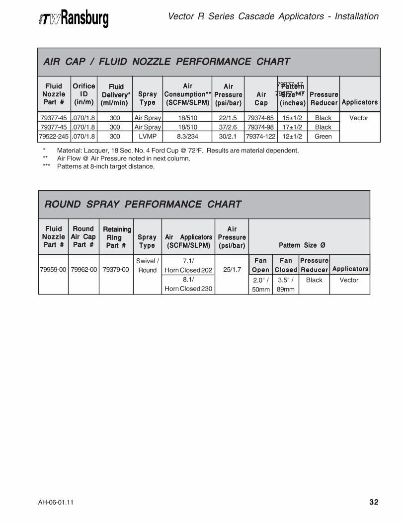
AH-06-01.11
Vector R Series Cascade Applicators - Installation
3232323232
* Material: Lacquer, 18 Sec. No. 4 Ford Cup @ 72oF. Results are material dependent.** Air Flow @ Air Pressure noted in next column.*** Patterns at 8-inch target distance.
79377-45
79377-45
79522-245
FluidFluidFluidFluidFluid
NozzleNozzleNozzleNozzleNozzle
Part #Part #Part #Part #Part #
FluidFluidFluidFluidFluid
Delivery* Delivery* Delivery* Delivery* Delivery*
(ml/min)(ml/min)(ml/min)(ml/min)(ml/min)
Orif iceOrificeOrificeOrificeOrifice
IDIDIDIDID
(in/m)(in/m)(in/m)(in/m)(in/m)
.070/1.8
.070/1.8
.070/1.8
AIR CAP / FLUID NOZZLE PERFORMANCE CHARTAIR CAP / FLUID NOZZLE PERFORMANCE CHARTAIR CAP / FLUID NOZZLE PERFORMANCE CHARTAIR CAP / FLUID NOZZLE PERFORMANCE CHARTAIR CAP / FLUID NOZZLE PERFORMANCE CHART
300
300
300
SpraySpraySpraySpraySpray
TypeTypeTypeTypeType
Air Spray
Air Spray
LVMP
A i rA i rA i rA i rA i r
Consumption**Consumption**Consumption**Consumption**Consumption**
(SCFM/SLPM)(SCFM/SLPM)(SCFM/SLPM)(SCFM/SLPM)(SCFM/SLPM)
18/510
18/510
8.3/234
A i rA i rA i rA i rA i r
PressurePressurePressurePressurePressure
(psi/bar)(psi/bar)(psi/bar)(psi/bar)(psi/bar)
22/1.5
37/2.6
30/2.1
A i rA i rA i rA i rA i r
C a pC a pC a pC a pC a p
79374-65
79374-98
79374-122
PatternPatternPatternPatternPattern
S ize***S ize***S ize***S ize***S ize***
( inches)( inches)( inches)( inches)( inches)
15±1/2
17±1/2
12±1/2
PressurePressurePressurePressurePressure
ReducerReducerReducerReducerReducer
Black
Black
Green
Appl icatorsAppl icatorsAppl icatorsAppl icatorsAppl icators
Vector
79377-47
79377-147
79959-00
FluidFluidFluidFluidFluid
NozzleNozzleNozzleNozzleNozzle
Part #Part #Part #Part #Part #
RetainingRetainingRetainingRetainingRetaining
RingRingRingRingRing
Part # Part # Part # Part # Part #
RoundRoundRoundRoundRound
Air CapAir CapAir CapAir CapAir Cap
Part #Part #Part #Part #Part #
79962-00
ROUND SPRAROUND SPRAROUND SPRAROUND SPRAROUND SPRAYYYYY PERFORMANCE CHAR PERFORMANCE CHAR PERFORMANCE CHAR PERFORMANCE CHAR PERFORMANCE CHARTTTTT
79379-00
SpraySpraySpraySpraySpray
TypeTypeTypeTypeType
Swivel /
Round
Air ApplicatorsAir ApplicatorsAir ApplicatorsAir ApplicatorsAir Applicators
(SCFM/SLPM)(SCFM/SLPM)(SCFM/SLPM)(SCFM/SLPM)(SCFM/SLPM)
7.1/
Horn Closed 202
8.1/
Horn Closed 230
A i rA i rA i rA i rA i r
PressurePressurePressurePressurePressure
(psi/bar)(psi/bar)(psi/bar)(psi/bar)(psi/bar)
25/1.7
Pattern Size ØPattern Size ØPattern Size ØPattern Size ØPattern Size Ø
3.5" /
89mm
Black Vector
FanFanFanFanFan
OpenOpenOpenOpenOpen
FanFanFanFanFan
ClosedClosedClosedClosedClosed
PressurePressurePressurePressurePressure
ReducerReducerReducerReducerReducer Appl icatorsAppl icatorsAppl icatorsAppl icatorsAppl icators
2.0" /
50mm
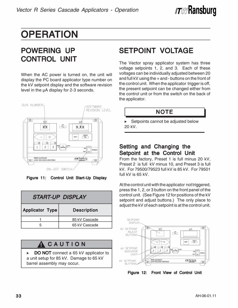
AH-06-01.11
Vector R Series Cascade Applicators - Operation
3333333333
OPERAOPERAOPERAOPERAOPERATIONTIONTIONTIONTION
SETPOINTSETPOINTSETPOINTSETPOINTSETPOINT VOL VOL VOL VOL VOLTTTTTAGEAGEAGEAGEAGE
The Vector spray applicator system has threevoltage setpoints 1, 2, and 3. Each of thesevoltages can be individually adjusted between 20and full kV using the + and - buttons on the front ofthe control unit. When the applicator trigger is off,the present setpoint can be changed either fromthe control unit or from the switch on the back ofthe applicator.
>Setpoints cannot be adjusted below
20 kV.
NOTENOTENOTENOTENOTE
Figure 12: Front View of Control UnitFigure 12: Front View of Control UnitFigure 12: Front View of Control UnitFigure 12: Front View of Control UnitFigure 12: Front View of Control Unit
POWERING UPPOWERING UPPOWERING UPPOWERING UPPOWERING UP
CONTROL UNITCONTROL UNITCONTROL UNITCONTROL UNITCONTROL UNIT
When the AC power is turned on, the unit willdisplay the PC board applicator type number onthe kV setpoint display and the software revisionlevel in the μA display for 2-3 seconds.
Figure 11: Control Unit Start-Up DisplayFigure 11: Control Unit Start-Up DisplayFigure 11: Control Unit Start-Up DisplayFigure 11: Control Unit Start-Up DisplayFigure 11: Control Unit Start-Up Display
DescriptionDescriptionDescriptionDescriptionDescriptionApplicator TypeApplicator TypeApplicator TypeApplicator TypeApplicator Type
1
5
ST ST ST ST STARARARARARTTTTT-UP-UP-UP-UP-UP DISPLA DISPLA DISPLA DISPLA DISPLAYYYYY
85 kV Cascade
65 kV Cascade
>DO NOTDO NOTDO NOTDO NOTDO NOT connect a 65 kV applicator to
a unit setup for 85 kV. Damage to 65 kVbarrel assembly may occur.
C A U T I O NC A U T I O NC A U T I O NC A U T I O NC A U T I O N!!!!!
Setting and Changing theSetting and Changing theSetting and Changing theSetting and Changing theSetting and Changing the
Setpoint at the Control UnitSetpoint at the Control UnitSetpoint at the Control UnitSetpoint at the Control UnitSetpoint at the Control UnitFrom the factory, Preset 1 is full minus 20 kV,Preset 2 is full kV minus 10, and Preset 3 is fullkV. For 79500/79523 full kV is 85 kV. For 79501full kV is 65 kV.
At the control unit with the applicator not triggered,press the 1, 2, or 3 button on the front panel of thecontrol unit. (See Figure 12 for positions of the kVsetpoint and adjust buttons.) The only place toadjust the kV of each setpoint is at the control unit.
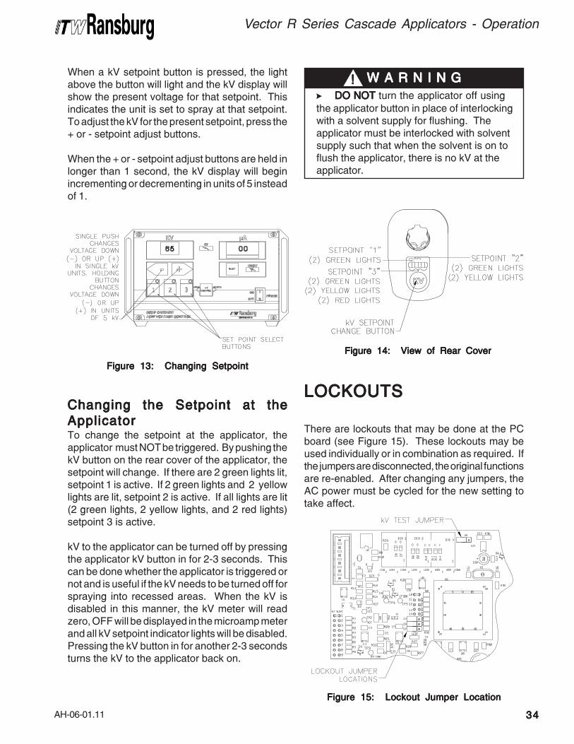
AH-06-01.11
Vector R Series Cascade Applicators - Operation
3434343434
When a kV setpoint button is pressed, the lightabove the button will light and the kV display willshow the present voltage for that setpoint. Thisindicates the unit is set to spray at that setpoint.To adjust the kV for the present setpoint, press the+ or - setpoint adjust buttons.
When the + or - setpoint adjust buttons are held inlonger than 1 second, the kV display will beginincrementing or decrementing in units of 5 insteadof 1.
>DO NOTDO NOTDO NOTDO NOTDO NOT turn the applicator off using
the applicator button in place of interlockingwith a solvent supply for flushing. Theapplicator must be interlocked with solventsupply such that when the solvent is on toflush the applicator, there is no kV at theapplicator.
W A R N I N GW A R N I N GW A R N I N GW A R N I N GW A R N I N G!!!!!
Figure 13: Changing SetpointFigure 13: Changing SetpointFigure 13: Changing SetpointFigure 13: Changing SetpointFigure 13: Changing Setpoint
Changing the Setpoint at theChanging the Setpoint at theChanging the Setpoint at theChanging the Setpoint at theChanging the Setpoint at the
ApplicatorApplicatorApplicatorApplicatorApplicatorTo change the setpoint at the applicator, theapplicator must NOT be triggered. By pushing thekV button on the rear cover of the applicator, thesetpoint will change. If there are 2 green lights lit,setpoint 1 is active. If 2 green lights and 2 yellowlights are lit, setpoint 2 is active. If all lights are lit(2 green lights, 2 yellow lights, and 2 red lights)setpoint 3 is active.
kV to the applicator can be turned off by pressingthe applicator kV button in for 2-3 seconds. Thiscan be done whether the applicator is triggered ornot and is useful if the kV needs to be turned off forspraying into recessed areas. When the kV isdisabled in this manner, the kV meter will readzero, OFF will be displayed in the microamp meterand all kV setpoint indicator lights will be disabled.Pressing the kV button in for another 2-3 secondsturns the kV to the applicator back on.
Figure 14: View of Rear CoverFigure 14: View of Rear CoverFigure 14: View of Rear CoverFigure 14: View of Rear CoverFigure 14: View of Rear Cover
LOCKOUTSLOCKOUTSLOCKOUTSLOCKOUTSLOCKOUTS
There are lockouts that may be done at the PCboard (see Figure 15). These lockouts may beused individually or in combination as required. Ifthe jumpers are disconnected, the original functionsare re-enabled. After changing any jumpers, theAC power must be cycled for the new setting totake affect.
Figure 15: Lockout Jumper LocationFigure 15: Lockout Jumper LocationFigure 15: Lockout Jumper LocationFigure 15: Lockout Jumper LocationFigure 15: Lockout Jumper Location
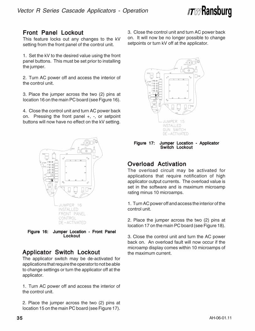
AH-06-01.11
Vector R Series Cascade Applicators - Operation
3535353535
Front Panel LockoutFront Panel LockoutFront Panel LockoutFront Panel LockoutFront Panel LockoutThis feature locks out any changes to the kVsetting from the front panel of the control unit.
1. Set the kV to the desired value using the frontpanel buttons. This must be set prior to installingthe jumper.
2. Turn AC power off and access the interior ofthe control unit.
3. Place the jumper across the two (2) pins atlocation 16 on the main PC board (see Figure 16).
4. Close the control unit and turn AC power backon. Pressing the front panel +, -, or setpointbuttons will now have no effect on the kV setting.
Figure 16: Jumper Location - Front PanelFigure 16: Jumper Location - Front PanelFigure 16: Jumper Location - Front PanelFigure 16: Jumper Location - Front PanelFigure 16: Jumper Location - Front PanelLockoutLockoutLockoutLockoutLockout
Applicator Switch LockoutApplicator Switch LockoutApplicator Switch LockoutApplicator Switch LockoutApplicator Switch LockoutThe applicator switch may be de-activated forapplications that require the operator to not be ableto change settings or turn the applicator off at theapplicator.
1. Turn AC power off and access the interior ofthe control unit.
2. Place the jumper across the two (2) pins atlocation 15 on the main PC board (see Figure 17).
Figure 17: Jumper Location - ApplicatorFigure 17: Jumper Location - ApplicatorFigure 17: Jumper Location - ApplicatorFigure 17: Jumper Location - ApplicatorFigure 17: Jumper Location - ApplicatorSwitch LockoutSwitch LockoutSwitch LockoutSwitch LockoutSwitch Lockout
3. Close the control unit and turn AC power backon. It will now be no longer possible to changesetpoints or turn kV off at the applicator.
Overload ActivationOverload ActivationOverload ActivationOverload ActivationOverload ActivationThe overload circuit may be activated forapplications that require notification of highapplicator output currents. The overload value isset in the software and is maximum microamprating minus 10 microamps.
1. Turn AC power off and access the interior of thecontrol unit.
2. Place the jumper across the two (2) pins atlocation 17 on the main PC board (see Figure 18).
3. Close the control unit and turn the AC powerback on. An overload fault will now occur if themicroamp display comes within 10 microamps ofthe maximum current.
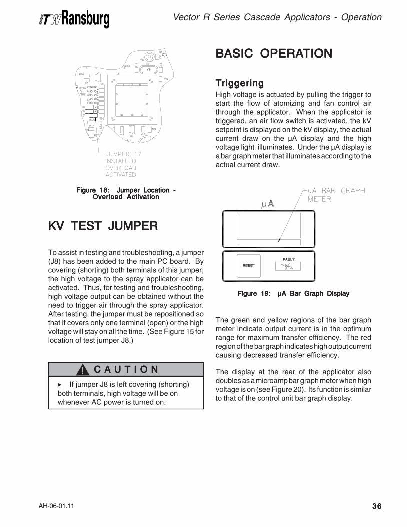
AH-06-01.11
Vector R Series Cascade Applicators - Operation
3636363636
Figure 18: Jumper Location -Figure 18: Jumper Location -Figure 18: Jumper Location -Figure 18: Jumper Location -Figure 18: Jumper Location -Overload ActivationOverload ActivationOverload ActivationOverload ActivationOverload Activation
BASIC OPERABASIC OPERABASIC OPERABASIC OPERABASIC OPERATIONTIONTIONTIONTION
TTTTTriggeringriggeringriggeringriggeringriggeringHigh voltage is actuated by pulling the trigger tostart the flow of atomizing and fan control airthrough the applicator. When the applicator istriggered, an air flow switch is activated, the kVsetpoint is displayed on the kV display, the actualcurrent draw on the μA display and the highvoltage light illuminates. Under the μA display isa bar graph meter that illuminates according to theactual current draw.
Figure 19: μA Bar Graph DisplayFigure 19: μA Bar Graph DisplayFigure 19: μA Bar Graph DisplayFigure 19: μA Bar Graph DisplayFigure 19: μA Bar Graph Display
The green and yellow regions of the bar graphmeter indicate output current is in the optimumrange for maximum transfer efficiency. The redregion of the bar graph indicates high output currentcausing decreased transfer efficiency.
The display at the rear of the applicator alsodoubles as a microamp bar graph meter when highvoltage is on (see Figure 20). Its function is similarto that of the control unit bar graph display.
KV TEST JUMPERKV TEST JUMPERKV TEST JUMPERKV TEST JUMPERKV TEST JUMPER
To assist in testing and troubleshooting, a jumper(J8) has been added to the main PC board. Bycovering (shorting) both terminals of this jumper,the high voltage to the spray applicator can beactivated. Thus, for testing and troubleshooting,high voltage output can be obtained without theneed to trigger air through the spray applicator.After testing, the jumper must be repositioned sothat it covers only one terminal (open) or the highvoltage will stay on all the time. (See Figure 15 forlocation of test jumper J8.)
>If jumper J8 is left covering (shorting)
both terminals, high voltage will be onwhenever AC power is turned on.
C A U T I O NC A U T I O NC A U T I O NC A U T I O NC A U T I O N!!!!!
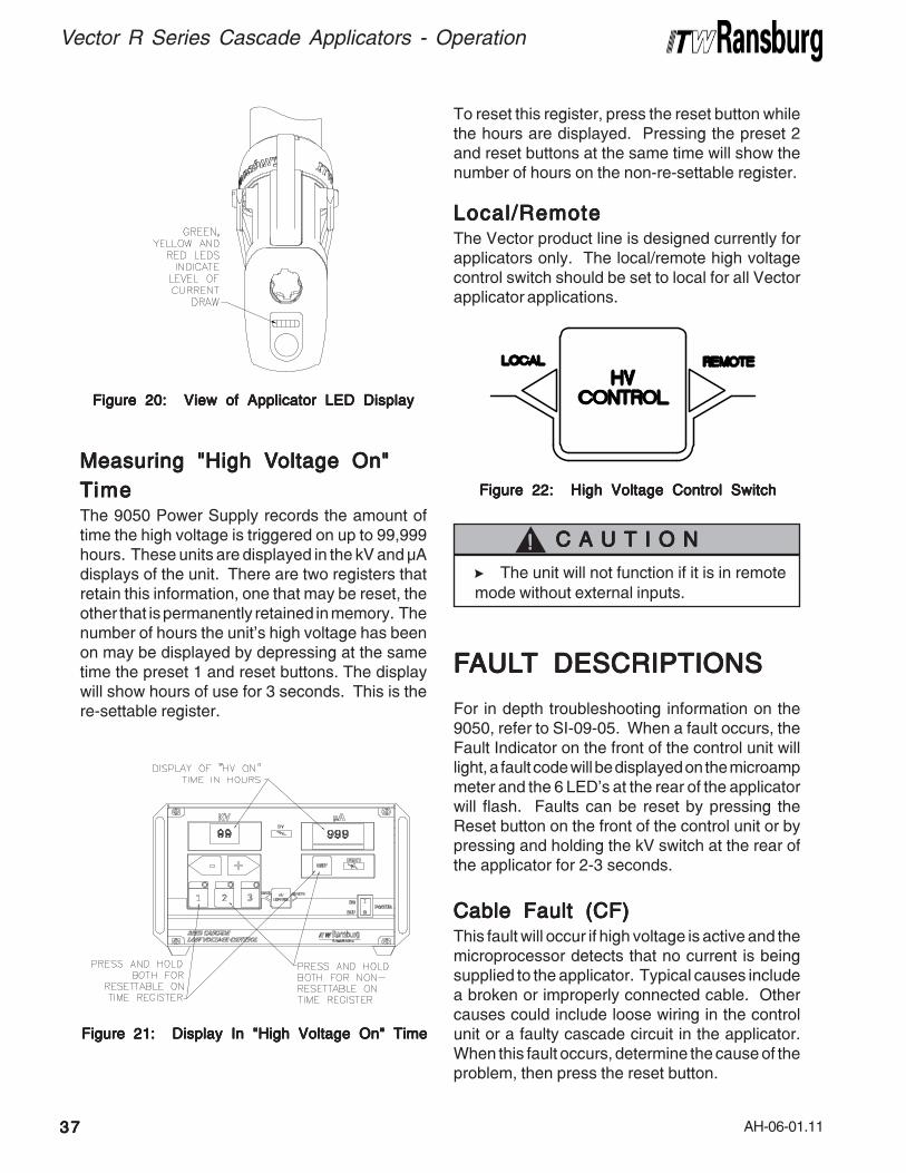
AH-06-01.11
Vector R Series Cascade Applicators - Operation
3737373737
Measuring "High VMeasuring "High VMeasuring "High VMeasuring "High VMeasuring "High Voltage On"oltage On"oltage On"oltage On"oltage On"
TTTTTimeimeimeimeimeThe 9050 Power Supply records the amount oftime the high voltage is triggered on up to 99,999hours. These units are displayed in the kV and μAdisplays of the unit. There are two registers thatretain this information, one that may be reset, theother that is permanently retained in memory. Thenumber of hours the unit's high voltage has beenon may be displayed by depressing at the sametime the preset 1 and reset buttons. The displaywill show hours of use for 3 seconds. This is there-settable register.
Figure 20: View of Applicator LED DisplayFigure 20: View of Applicator LED DisplayFigure 20: View of Applicator LED DisplayFigure 20: View of Applicator LED DisplayFigure 20: View of Applicator LED Display
Figure 21: Display In "High Voltage On" TimeFigure 21: Display In "High Voltage On" TimeFigure 21: Display In "High Voltage On" TimeFigure 21: Display In "High Voltage On" TimeFigure 21: Display In "High Voltage On" Time
To reset this register, press the reset button whilethe hours are displayed. Pressing the preset 2and reset buttons at the same time will show thenumber of hours on the non-re-settable register.
Local/RemoteLocal/RemoteLocal/RemoteLocal/RemoteLocal/RemoteThe Vector product line is designed currently forapplicators only. The local/remote high voltagecontrol switch should be set to local for all Vectorapplicator applications.
Figure 22: High Voltage Control SwitchFigure 22: High Voltage Control SwitchFigure 22: High Voltage Control SwitchFigure 22: High Voltage Control SwitchFigure 22: High Voltage Control Switch
FFFFFAULAULAULAULAULTTTTT DESCRIPTIONS DESCRIPTIONS DESCRIPTIONS DESCRIPTIONS DESCRIPTIONS
For in depth troubleshooting information on the9050, refer to SI-09-05. When a fault occurs, theFault Indicator on the front of the control unit willlight, a fault code will be displayed on the microampmeter and the 6 LED’s at the rear of the applicatorwill flash. Faults can be reset by pressing theReset button on the front of the control unit or bypressing and holding the kV switch at the rear ofthe applicator for 2-3 seconds.
Cable Fault (CF)Cable Fault (CF)Cable Fault (CF)Cable Fault (CF)Cable Fault (CF)This fault will occur if high voltage is active and themicroprocessor detects that no current is beingsupplied to the applicator. Typical causes includea broken or improperly connected cable. Othercauses could include loose wiring in the controlunit or a faulty cascade circuit in the applicator.When this fault occurs, determine the cause of theproblem, then press the reset button.
>The unit will not function if it is in remote
mode without external inputs.
C A U T I O NC A U T I O NC A U T I O NC A U T I O NC A U T I O N!!!!!
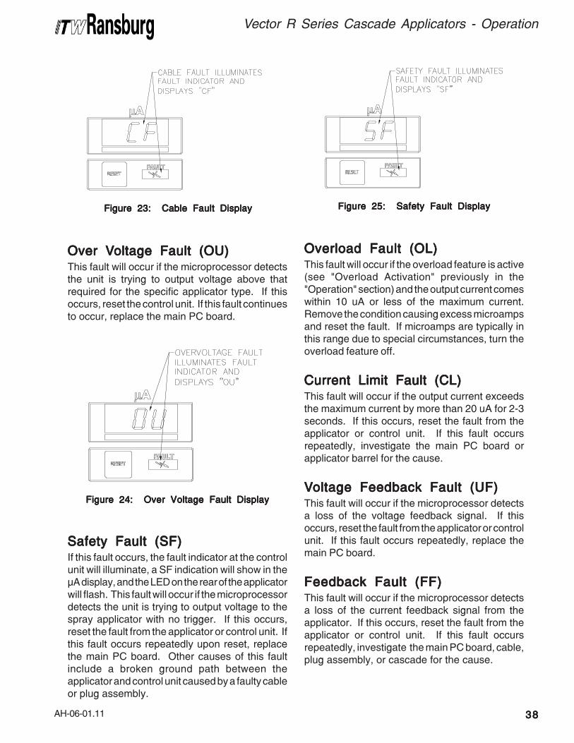
AH-06-01.11
Vector R Series Cascade Applicators - Operation
3838383838
Figure 23: Cable Fault DisplayFigure 23: Cable Fault DisplayFigure 23: Cable Fault DisplayFigure 23: Cable Fault DisplayFigure 23: Cable Fault Display
Over VOver VOver VOver VOver Voltage Fault (OU)oltage Fault (OU)oltage Fault (OU)oltage Fault (OU)oltage Fault (OU)This fault will occur if the microprocessor detectsthe unit is trying to output voltage above thatrequired for the specific applicator type. If thisoccurs, reset the control unit. If this fault continuesto occur, replace the main PC board.
Figure 24: Over Voltage Fault DisplayFigure 24: Over Voltage Fault DisplayFigure 24: Over Voltage Fault DisplayFigure 24: Over Voltage Fault DisplayFigure 24: Over Voltage Fault Display
Safety Fault (SF)Safety Fault (SF)Safety Fault (SF)Safety Fault (SF)Safety Fault (SF)If this fault occurs, the fault indicator at the controlunit will illuminate, a SF indication will show in theμA display, and the LED on the rear of the applicatorwill flash. This fault will occur if the microprocessordetects the unit is trying to output voltage to thespray applicator with no trigger. If this occurs,reset the fault from the applicator or control unit. Ifthis fault occurs repeatedly upon reset, replacethe main PC board. Other causes of this faultinclude a broken ground path between theapplicator and control unit caused by a faulty cableor plug assembly.
Figure 25: Safety Fault DisplayFigure 25: Safety Fault DisplayFigure 25: Safety Fault DisplayFigure 25: Safety Fault DisplayFigure 25: Safety Fault Display
Overload Fault (OL)Overload Fault (OL)Overload Fault (OL)Overload Fault (OL)Overload Fault (OL)This fault will occur if the overload feature is active(see "Overload Activation" previously in the"Operation" section) and the output current comeswithin 10 uA or less of the maximum current.Remove the condition causing excess microampsand reset the fault. If microamps are typically inthis range due to special circumstances, turn theoverload feature off.
Current Limit Fault (CL)Current Limit Fault (CL)Current Limit Fault (CL)Current Limit Fault (CL)Current Limit Fault (CL)This fault will occur if the output current exceedsthe maximum current by more than 20 uA for 2-3seconds. If this occurs, reset the fault from theapplicator or control unit. If this fault occursrepeatedly, investigate the main PC board orapplicator barrel for the cause.
VVVVVoltage Feedback Fault (UF)oltage Feedback Fault (UF)oltage Feedback Fault (UF)oltage Feedback Fault (UF)oltage Feedback Fault (UF)This fault will occur if the microprocessor detectsa loss of the voltage feedback signal. If thisoccurs, reset the fault from the applicator or controlunit. If this fault occurs repeatedly, replace themain PC board.
Feedback Fault (FF)Feedback Fault (FF)Feedback Fault (FF)Feedback Fault (FF)Feedback Fault (FF)This fault will occur if the microprocessor detectsa loss of the current feedback signal from theapplicator. If this occurs, reset the fault from theapplicator or control unit. If this fault occursrepeatedly, investigate the main PC board, cable,plug assembly, or cascade for the cause.
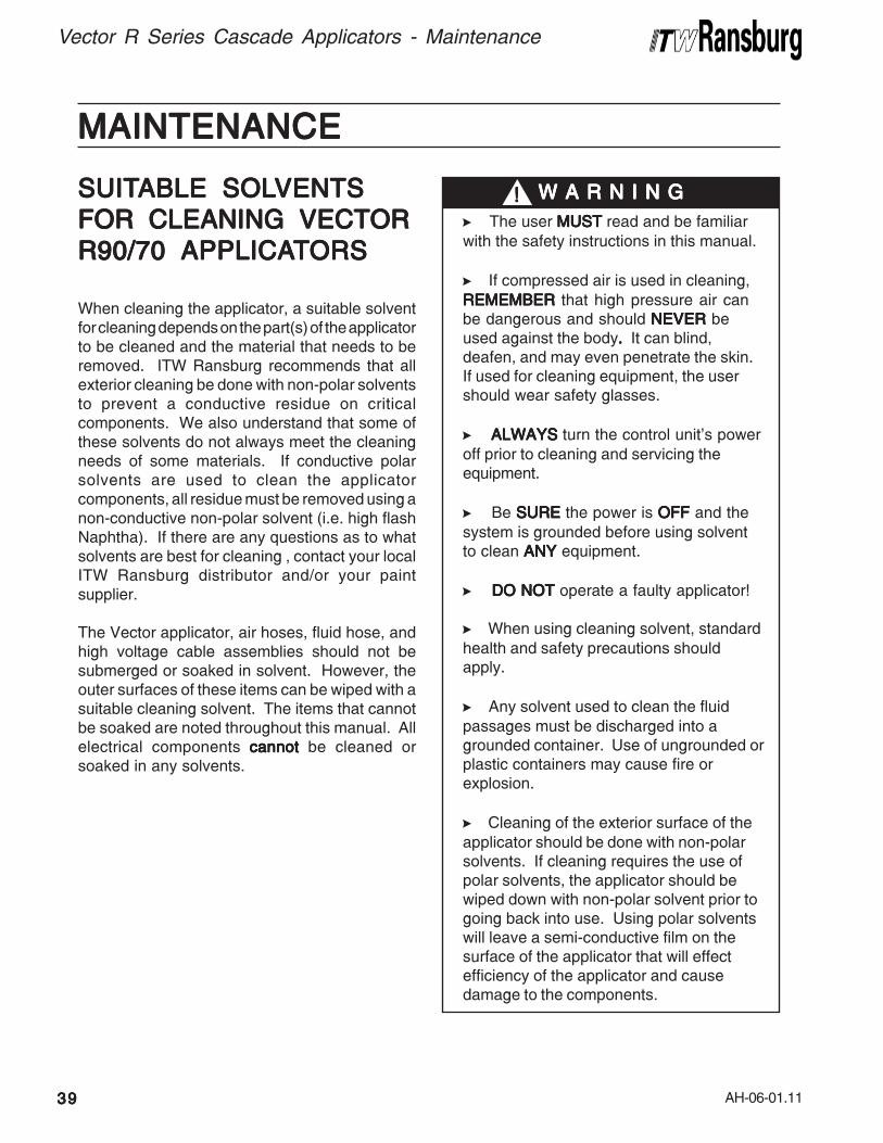
AH-06-01.11
MAINTENANCEMAINTENANCEMAINTENANCEMAINTENANCEMAINTENANCE
Vector R Series Cascade Applicators - Maintenance
3939393939
>The user MUSTMUSTMUSTMUSTMUST read and be familiar
with the safety instructions in this manual.
>If compressed air is used in cleaning,
REMEMBER REMEMBER REMEMBER REMEMBER REMEMBER that high pressure air canbe dangerous and should NEVER NEVER NEVER NEVER NEVER beused against the body..... It can blind,deafen, and may even penetrate the skin.If used for cleaning equipment, the usershould wear safety glasses.
>ALWAYSALWAYSALWAYSALWAYSALWAYS turn the control unit's power
off prior to cleaning and servicing theequipment.
>Be SURESURESURESURESURE the power is OFFOFFOFFOFFOFF and the
system is grounded before using solventto clean ANYANYANYANYANY equipment.
>DO NOT DO NOT DO NOT DO NOT DO NOT operate a faulty applicator!
>When using cleaning solvent, standard
health and safety precautions shouldapply.
>Any solvent used to clean the fluid
passages must be discharged into agrounded container. Use of ungrounded orplastic containers may cause fire orexplosion.
>Cleaning of the exterior surface of the
applicator should be done with non-polarsolvents. If cleaning requires the use ofpolar solvents, the applicator should bewiped down with non-polar solvent prior togoing back into use. Using polar solventswill leave a semi-conductive film on thesurface of the applicator that will effectefficiency of the applicator and causedamage to the components.
W A R N I N GW A R N I N GW A R N I N GW A R N I N GW A R N I N G!!!!!SUITSUITSUITSUITSUITABLE SOLABLE SOLABLE SOLABLE SOLABLE SOLVENTSVENTSVENTSVENTSVENTS
FOR CLEANING VECTORFOR CLEANING VECTORFOR CLEANING VECTORFOR CLEANING VECTORFOR CLEANING VECTOR
R90/70 APPLICAR90/70 APPLICAR90/70 APPLICAR90/70 APPLICAR90/70 APPLICATTTTTORSORSORSORSORS
When cleaning the applicator, a suitable solventfor cleaning depends on the part(s) of the applicatorto be cleaned and the material that needs to beremoved. ITW Ransburg recommends that allexterior cleaning be done with non-polar solventsto prevent a conductive residue on criticalcomponents. We also understand that some ofthese solvents do not always meet the cleaningneeds of some materials. If conductive polarsolvents are used to clean the applicatorcomponents, all residue must be removed using anon-conductive non-polar solvent (i.e. high flashNaphtha). If there are any questions as to whatsolvents are best for cleaning , contact your localITW Ransburg distributor and/or your paintsupplier.
The Vector applicator, air hoses, fluid hose, andhigh voltage cable assemblies should not besubmerged or soaked in solvent. However, theouter surfaces of these items can be wiped with asuitable cleaning solvent. The items that cannotbe soaked are noted throughout this manual. Allelectrical components cannotcannotcannotcannotcannot be cleaned orsoaked in any solvents.
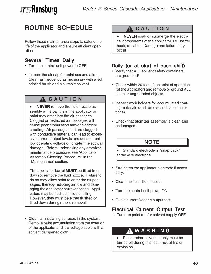
AH-06-01.11
Vector R Series Cascade Applicators - Maintenance
4040404040
ROUTINE SCHEDULEROUTINE SCHEDULEROUTINE SCHEDULEROUTINE SCHEDULEROUTINE SCHEDULE
Follow these maintenance steps to extend thelife of the applicator and ensure efficient oper-ation:
Several TSeveral TSeveral TSeveral TSeveral Times Dailyimes Dailyimes Dailyimes Dailyimes Daily• Turn the control unit power to OFF!
• Inspect the air cap for paint accumulation.Clean as frequently as necessary with a softbristled brush and a suitable solvent.
• Clean all insulating surfaces in the system.Remove paint accumulation from the exteriorof the applicator and low voltage cable with asolvent dampened cloth.
Daily (or at start of each shift)Daily (or at start of each shift)Daily (or at start of each shift)Daily (or at start of each shift)Daily (or at start of each shift)• Verify that ALL solvent safety containers
are grounded!
• Check within 20 feet of the point of operation(of the applicator) and remove or ground ALLloose or ungrounded objects.
• Inspect work holders for accumulated coat-ing materials (and remove such accumula-tions).
• Check that atomizer assembly is clean andundamaged.
>NEVERNEVERNEVERNEVERNEVER soak or submerge the electri-
cal components of the applicator, i.e., barrel,hook, or cable. Damage and failure mayoccur.
C A U T I O NC A U T I O NC A U T I O NC A U T I O NC A U T I O N!!!!!
>NEVERNEVERNEVERNEVERNEVER remove the fluid nozzle as-
sembly while paint is in the applicator orpaint may enter into the air passages.Clogged or restricted air passages willcause poor atomization and/or electricalshorting. Air passages that are cloggedwith conductive material can lead to exces-sive current output levels and consequentlow operating voltage or long-term electricaldamage. Before undertaking any atomizermaintenance procedure, see "ApplicatorAssembly Cleaning Procedure" in the"Maintenance" section.
The applicator barrel MUSTMUSTMUSTMUSTMUST be tilted frontdown to remove the fluid nozzle. Failure todo so may allow paint to enter the air pas-sages, thereby reducing airflow and dam-aging the applicator barrel/cascade. Appli-cators may be flushed in lieu of tilting.However, they must be either flushed ortilted down during nozzle removal!
C A U T I O NC A U T I O NC A U T I O NC A U T I O NC A U T I O N!!!!!
• Straighten the applicator electrode if neces-sary.
• Clean the fluid filter, if used.
• Turn the control unit power ON.
• Run a current/voltage output test.
Electrical Current Output TElectrical Current Output TElectrical Current Output TElectrical Current Output TElectrical Current Output Testestestestest1. Turn the paint and/or solvent supply OFF.
>Standard electrode is "snap back"
spray wire electrode.
NOTENOTENOTENOTENOTE
>Paint and/or solvent supply must be
turned off during this test - risk of fire orexplosion.
W A R N I N GW A R N I N GW A R N I N GW A R N I N GW A R N I N G!!!!!
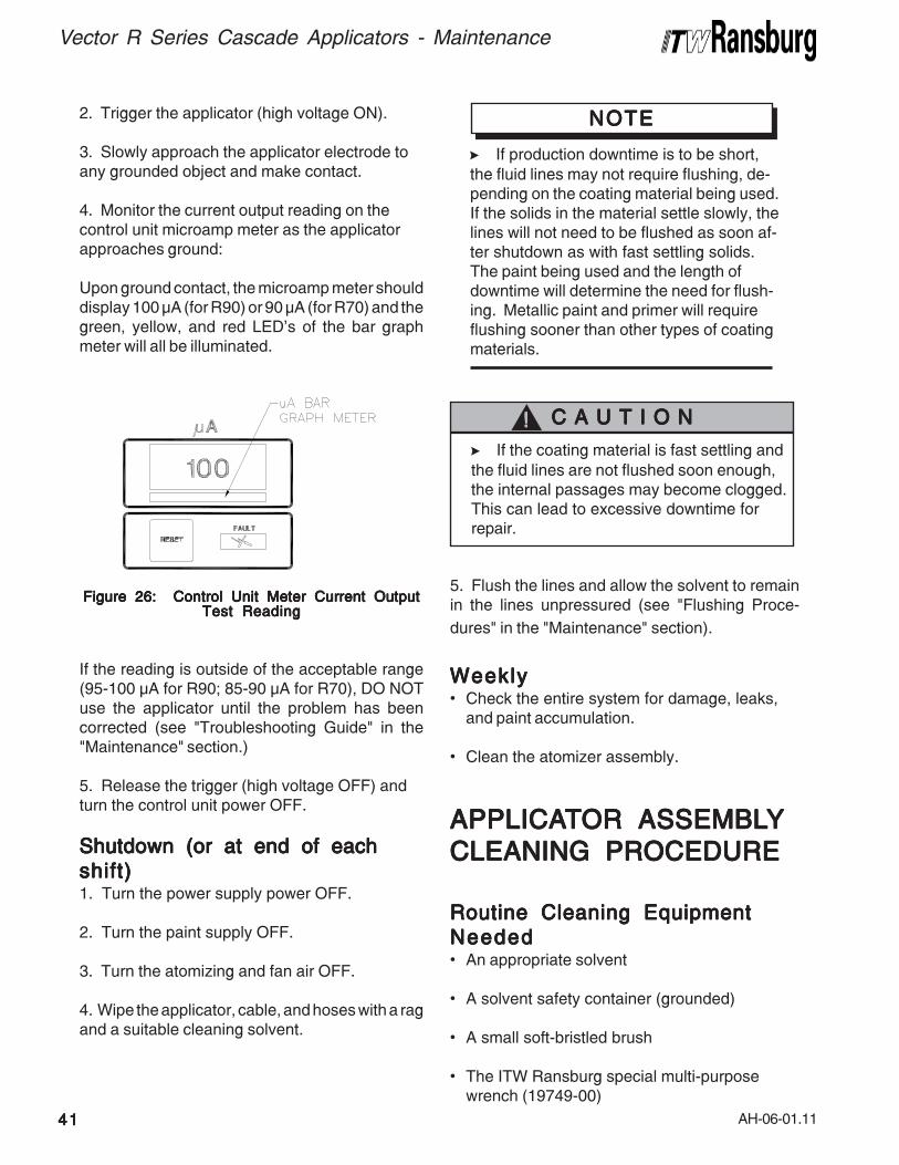
AH-06-01.11
Vector R Series Cascade Applicators - Maintenance
4141414141
>If production downtime is to be short,
the fluid lines may not require flushing, de-pending on the coating material being used.If the solids in the material settle slowly, thelines will not need to be flushed as soon af-ter shutdown as with fast settling solids.The paint being used and the length ofdowntime will determine the need for flush-ing. Metallic paint and primer will requireflushing sooner than other types of coatingmaterials.
NOTENOTENOTENOTENOTE2. Trigger the applicator (high voltage ON).
3. Slowly approach the applicator electrode toany grounded object and make contact.
4. Monitor the current output reading on thecontrol unit microamp meter as the applicatorapproaches ground:
Upon ground contact, the microamp meter shoulddisplay 100 μA (for R90) or 90 μA (for R70) and thegreen, yellow, and red LED's of the bar graphmeter will all be illuminated.
>If the coating material is fast settling and
the fluid lines are not flushed soon enough,the internal passages may become clogged.This can lead to excessive downtime forrepair.
C A U T I O NC A U T I O NC A U T I O NC A U T I O NC A U T I O N!!!!!
Figure 26: Control Unit Meter Current OutputFigure 26: Control Unit Meter Current OutputFigure 26: Control Unit Meter Current OutputFigure 26: Control Unit Meter Current OutputFigure 26: Control Unit Meter Current OutputTest ReadingTest ReadingTest ReadingTest ReadingTest Reading
If the reading is outside of the acceptable range(95-100 μA for R90; 85-90 μA for R70), DO NOTuse the applicator until the problem has beencorrected (see "Troubleshooting Guide" in the"Maintenance" section.)
5. Release the trigger (high voltage OFF) andturn the control unit power OFF.
Shutdown (or at end of eachShutdown (or at end of eachShutdown (or at end of eachShutdown (or at end of eachShutdown (or at end of each
shift)shift)shift)shift)shift)1. Turn the power supply power OFF.
2. Turn the paint supply OFF.
3. Turn the atomizing and fan air OFF.
4. Wipe the applicator, cable, and hoses with a ragand a suitable cleaning solvent.
5. Flush the lines and allow the solvent to remainin the lines unpressured (see "Flushing Proce-
dures" in the "Maintenance" section).
WeeklyWeeklyWeeklyWeeklyWeekly• Check the entire system for damage, leaks,
and paint accumulation.
• Clean the atomizer assembly.
APPLICAAPPLICAAPPLICAAPPLICAAPPLICATTTTTOR ASSEMBLOR ASSEMBLOR ASSEMBLOR ASSEMBLOR ASSEMBLYYYYY
CLEANING CLEANING CLEANING CLEANING CLEANING PROCEDUREPROCEDUREPROCEDUREPROCEDUREPROCEDURE
Routine Cleaning EquipmentRoutine Cleaning EquipmentRoutine Cleaning EquipmentRoutine Cleaning EquipmentRoutine Cleaning Equipment
NeededNeededNeededNeededNeeded• An appropriate solvent
• A solvent safety container (grounded)
• A small soft-bristled brush
• The ITW Ransburg special multi-purposewrench (19749-00)
AH-06-01.11
Vector R Series Cascade Applicators - Maintenance
4242424242
For efficient electrostatic operation, keep theapplicator’s exterior and low voltage cable free ofpaint accumulation. This prevents the loss ofvoltage to ground with a resultant reduction intransfer efficiency. Paint accumulation in andaround the air cap nozzles will reduce atomizationquality. Clean the air cap using clean solvent anda soft bristle brush as often as needed to ensuregood atomization.
Proceed as follows:1. Turn OFF the control unit power.
2. Release the trigger.
3. Turn the paint flow OFF.
4. See "Applicator Repair - Disassembly Pro-cedures" in the "Maintenance" section.
>To avoid damage to the fluid nozzle or
needle/electrode, the paint pressure MUSTMUSTMUSTMUSTMUSTbe released by triggering the applicator priorto removing the tip.
>The applicator barrel MUSTMUSTMUSTMUSTMUST be tilted
front down to remove the fluid nozzle.Failure to do so may allow paint to enter theair passages, thereby reducing airflow anddamaging the applicator barrel/cascade.Applicators may be flushed in lieu of tilting.However, they must be either flushed ortilted down during nozzle removal!
>The control unit power MUSTMUSTMUSTMUSTMUST be off
when removing the nozzles and/or duringany applicator maintenance.
C A U T I O NC A U T I O NC A U T I O NC A U T I O NC A U T I O N!!!!!
C A U T I O NC A U T I O NC A U T I O NC A U T I O NC A U T I O N!!!!!
>When installing or removing the fluid
nozzle, the applicator MUSTMUSTMUSTMUSTMUST be triggered.Failure to do so may cause damage to theelectrode or fluid nozzle. Such damage canresult in fluid leaks around the sealing areaof these components.
>Using any tool other than the ITW
Ransburg multi-purpose wrench (19749-00)to remove or install the fluid nozzle maycause damage.
>NEVERNEVERNEVERNEVERNEVER wrap the applicator, associ-
ated valves and tubing, and supportinghardware in plastic to keep it clean. Asurface charge may build up on the plasticsurface and discharge to the nearestgrounded object. Efficiency of the applica-tor will also be reduced and damage orfailure of the applicator components mayoccur. WRAPPING THE APPLICA- WRAPPING THE APPLICA- WRAPPING THE APPLICA- WRAPPING THE APPLICA- WRAPPING THE APPLICA-
TOR IN PLASTIC WILL VOID WAR-TOR IN PLASTIC WILL VOID WAR-TOR IN PLASTIC WILL VOID WAR-TOR IN PLASTIC WILL VOID WAR-TOR IN PLASTIC WILL VOID WAR-
RANTY. RANTY. RANTY. RANTY. RANTY. Only approved applicator coversshould be used.
W A R N I N GW A R N I N GW A R N I N GW A R N I N GW A R N I N G!!!!!
>Any broken or damaged components
should be replaced. Any damage to theapplicator may result in UNSAFE UNSAFE UNSAFE UNSAFE UNSAFE operat-ing conditions.
W A R N I N GW A R N I N GW A R N I N GW A R N I N GW A R N I N G!!!!!
5. Clean the applicator and associated partswith a soft brush and suitable solvent.
C A U T I O NC A U T I O NC A U T I O NC A U T I O NC A U T I O N!!!!!
>Metal tools and wire brushes must
NEVERNEVERNEVERNEVERNEVER be used. NEVER NEVER NEVER NEVER NEVER use a cleaningtool that is harder than the plastic parts. If adeposit cannot be removed with the solventand a rag or the soft brush, soak ONLY ONLY ONLY ONLY ONLY thepart in the solvent until the deposit can beremoved! NEVERNEVERNEVERNEVERNEVER soak the applicatorbody or barrel!
AH-06-01.11
Vector R Series Cascade Applicators- Maintenance
4343434343
FLUSHINGFLUSHINGFLUSHINGFLUSHINGFLUSHING
PROCEDURESPROCEDURESPROCEDURESPROCEDURESPROCEDURES
1. Turn OFF the control unit power.
>Whenever solvent is flushed through
the applicator the control unit power mustbe off.
W A R N I N GW A R N I N GW A R N I N GW A R N I N GW A R N I N G!!!!!
2. Turn the paint supply OFF.
3. Turn the atomizing air supply OFF.
4. Tilt the applicator down and trigger until it isclear of paint.
5. Connect the solvent supply.
6. Run solvent through the system until it runsclear.
>DO NOT DO NOT DO NOT DO NOT DO NOT allow the fluid lines to stand
empty without flushing first! This will causedried paint flaking and clogging of the fluidlines, applicator passages, and/or nozzles.
C A U T I O NC A U T I O NC A U T I O NC A U T I O NC A U T I O N!!!!!
APPLICAAPPLICAAPPLICAAPPLICAAPPLICATTTTTOR REPOR REPOR REPOR REPOR REPAIRAIRAIRAIRAIR
All repairs should be made on a clean, flat surface.If a vise is used to hold parts during service orrepair, DO NOT clamp onto plastic parts andalways pad the vise jaws!
The following parts should be thoroughly packedwith dielectric grease (LSCH0009-00) leaving NOair space or voids when assembling:
• All O-Rings (Teflon o-rings do not needlubrication)
• Needle Shaft Assembly
• Packing Tube
• Cartridge Assembly, Non-Adjustable
• Air Valve Rod Assembly
Apply sealant (7969-10) to the external threads ofthe following parts when assembling:
• Nut Air Valve Retaining (78635-00)
• Cap, Air Valve (79317-00)
Equipment RequiredEquipment RequiredEquipment RequiredEquipment RequiredEquipment Required• Special Multi-Purpose Wrench (19749-00)
• 3/32" Allen Wrench for Set Screws
• Screwdriver (blade)
• Dielectric Grease (LSCH0009-00)
• Sealant, Medium Strength (7969-10)
• Plastic or Wood Dowel Rod, 5/16" Diameter
>Any solvent used to clean the fluid
passages must be discharged into agrounded container. Use of ungrounded orplastic containers may cause fire or explo-sion.
W A R N I N GW A R N I N GW A R N I N GW A R N I N GW A R N I N G!!!!!
7. Disconnect the solvent supply.
8. Trigger the applicator until it is clear of solvent.After the preceding steps are complete, theapplicator is ready for color change, storage, ormaintenance.
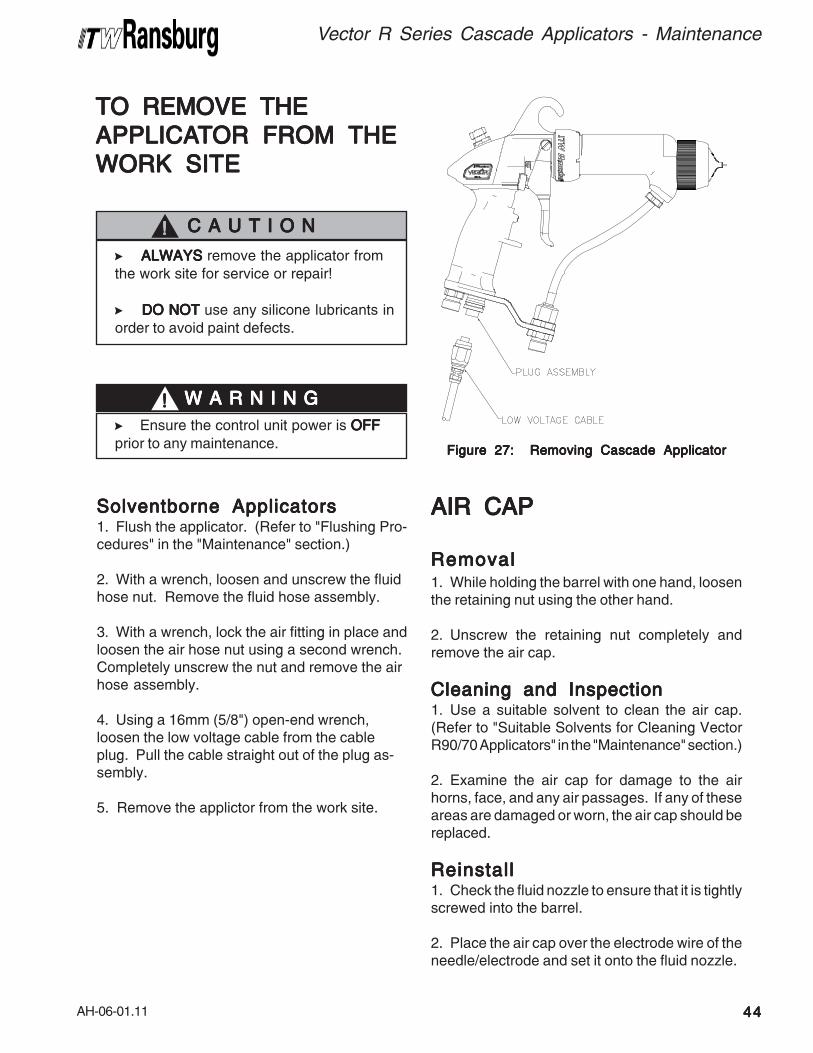
AH-06-01.11
Vector R Series Cascade Applicators - Maintenance
4444444444
TO REMOVE THETO REMOVE THETO REMOVE THETO REMOVE THETO REMOVE THE
APPLICAAPPLICAAPPLICAAPPLICAAPPLICATTTTTOR FROM THEOR FROM THEOR FROM THEOR FROM THEOR FROM THE
WORK SITEWORK SITEWORK SITEWORK SITEWORK SITE
Solventborne ApplicatorsSolventborne ApplicatorsSolventborne ApplicatorsSolventborne ApplicatorsSolventborne Applicators1. Flush the applicator. (Refer to "Flushing Pro-cedures" in the "Maintenance" section.)
2. With a wrench, loosen and unscrew the fluidhose nut. Remove the fluid hose assembly.
3. With a wrench, lock the air fitting in place andloosen the air hose nut using a second wrench.Completely unscrew the nut and remove the airhose assembly.
4. Using a 16mm (5/8") open-end wrench,loosen the low voltage cable from the cableplug. Pull the cable straight out of the plug as-sembly.
5. Remove the applictor from the work site.
AIR CAPAIR CAPAIR CAPAIR CAPAIR CAP
RemovalRemovalRemovalRemovalRemoval1. While holding the barrel with one hand, loosenthe retaining nut using the other hand.
2. Unscrew the retaining nut completely andremove the air cap.
Cleaning and InspectionCleaning and InspectionCleaning and InspectionCleaning and InspectionCleaning and Inspection1. Use a suitable solvent to clean the air cap.(Refer to "Suitable Solvents for Cleaning VectorR90/70 Applicators" in the "Maintenance" section.)
2. Examine the air cap for damage to the airhorns, face, and any air passages. If any of theseareas are damaged or worn, the air cap should bereplaced.
ReinstallReinstallReinstallReinstallReinstall1. Check the fluid nozzle to ensure that it is tightlyscrewed into the barrel.
2. Place the air cap over the electrode wire of theneedle/electrode and set it onto the fluid nozzle.
>ALWAYSALWAYSALWAYSALWAYSALWAYS remove the applicator from
the work site for service or repair!
>DO NOTDO NOTDO NOTDO NOTDO NOT use any silicone lubricants in
order to avoid paint defects.
C A U T I O NC A U T I O NC A U T I O NC A U T I O NC A U T I O N!!!!!
>Ensure the control unit power is OFFOFFOFFOFFOFF
prior to any maintenance.
W A R N I N GW A R N I N GW A R N I N GW A R N I N GW A R N I N G!!!!!
Figure 27: Removing Cascade ApplicatorFigure 27: Removing Cascade ApplicatorFigure 27: Removing Cascade ApplicatorFigure 27: Removing Cascade ApplicatorFigure 27: Removing Cascade Applicator

AH-06-01.11
Vector R Series Cascade Applicators- Maintenance
4545454545
3. Place the retaining nut over the air cap andbegin screwing it onto the barrel.
4. Before securing the retainer nut to the barrel,position the air cap for the desired spray patternposition.
FLUID NOZZLEFLUID NOZZLEFLUID NOZZLEFLUID NOZZLEFLUID NOZZLE(Refer to Figure 28)(Refer to Figure 28)(Refer to Figure 28)(Refer to Figure 28)(Refer to Figure 28)
RemovalRemovalRemovalRemovalRemoval1. Remove the air cap from the applicator (refer to"Air Cap - Removal" in the "Maintenance" section).
2. Tilt the applicator forward and pull the trigger tomake sure that all fluid in the applicator is drainedout.
3. While holding the applicator assembly with thetrigger pulled back, remove the fluid nozzle withthe open-end of the special multi-purpose wrench.
>The applicator barrel MUSTMUSTMUSTMUSTMUST be tilted
front down to remove the fluid nozzle.Failure to do so may allow paint to enter theair passages, thereby reducing airflow anddamaging the applicator barrel. Applicatorsmay be flushed in lieu of tilting. However,they MUSTMUSTMUSTMUSTMUST be either flushed or tilted duringnozzle removal!
C A U T I O NC A U T I O NC A U T I O NC A U T I O NC A U T I O N!!!!!
Figure 28: Removal of Fluid NozzleFigure 28: Removal of Fluid NozzleFigure 28: Removal of Fluid NozzleFigure 28: Removal of Fluid NozzleFigure 28: Removal of Fluid Nozzle
>To keep the needle/electrode from
unscrewing from the needle shaft, theapplicator's trigger should be actuated topull the needle/electrode away from thefluid nozzle.
NOTENOTENOTENOTENOTE
Cleaning and InspectionCleaning and InspectionCleaning and InspectionCleaning and InspectionCleaning and Inspection1. Use a suitable solvent to clean the fluid nozzle
2. Examine the fluid nozzle for damage to the airpassages and the fluid nozzle tip. Also, examinethe needle seat for damage or wear. If anydamaged or any worn areas are found, the fluidnozzle must be replaced.
Figure 29: Air Cap, Fluid Nozzle, and NutFigure 29: Air Cap, Fluid Nozzle, and NutFigure 29: Air Cap, Fluid Nozzle, and NutFigure 29: Air Cap, Fluid Nozzle, and NutFigure 29: Air Cap, Fluid Nozzle, and Nut
>If the fluid nozzle is replaced, there is
a good chance that the needle/electrodeassembly will need to be replaced also. Aworn needle/electrode assembly may notalways seat well in a new fluid nozzle.
NOTENOTENOTENOTENOTE
1
2
3 4 5
6
1 - Retaining Ring2 - O-Ring, Teflon Encapsulated3 - Air Cap4 - Fluid Nozzle5 - Electrode Assembly6 - Barrel Assembly
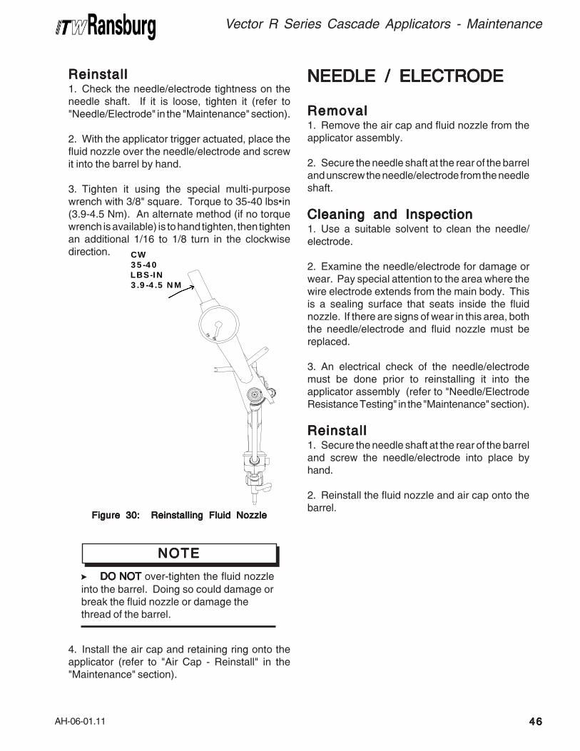
AH-06-01.11
Vector R Series Cascade Applicators - Maintenance
4646464646
ReinstallReinstallReinstallReinstallReinstall1. Check the needle/electrode tightness on theneedle shaft. If it is loose, tighten it (refer to"Needle/Electrode" in the "Maintenance" section).
2. With the applicator trigger actuated, place thefluid nozzle over the needle/electrode and screwit into the barrel by hand.
3. Tighten it using the special multi-purposewrench with 3/8" square. Torque to 35-40 lbs•in(3.9-4.5 Nm). An alternate method (if no torquewrench is available) is to hand tighten, then tightenan additional 1/16 to 1/8 turn in the clockwisedirection.
4. Install the air cap and retaining ring onto theapplicator (refer to "Air Cap - Reinstall" in the"Maintenance" section).
Figure 30: Reinstalling Fluid NozzleFigure 30: Reinstalling Fluid NozzleFigure 30: Reinstalling Fluid NozzleFigure 30: Reinstalling Fluid NozzleFigure 30: Reinstalling Fluid Nozzle
>DO NOTDO NOTDO NOTDO NOTDO NOT over-tighten the fluid nozzle
into the barrel. Doing so could damage orbreak the fluid nozzle or damage thethread of the barrel.
NOTENOTENOTENOTENOTE
NEEDLE / ELECTRODENEEDLE / ELECTRODENEEDLE / ELECTRODENEEDLE / ELECTRODENEEDLE / ELECTRODE
RemovalRemovalRemovalRemovalRemoval1. Remove the air cap and fluid nozzle from theapplicator assembly.
2. Secure the needle shaft at the rear of the barreland unscrew the needle/electrode from the needleshaft.
Cleaning and InspectionCleaning and InspectionCleaning and InspectionCleaning and InspectionCleaning and Inspection1. Use a suitable solvent to clean the needle/electrode.
2. Examine the needle/electrode for damage orwear. Pay special attention to the area where thewire electrode extends from the main body. Thisis a sealing surface that seats inside the fluidnozzle. If there are signs of wear in this area, boththe needle/electrode and fluid nozzle must bereplaced.
3. An electrical check of the needle/electrodemust be done prior to reinstalling it into theapplicator assembly (refer to "Needle/ElectrodeResistance Testing" in the "Maintenance" section).
ReinstallReinstallReinstallReinstallReinstall1. Secure the needle shaft at the rear of the barreland screw the needle/electrode into place byhand.
2. Reinstall the fluid nozzle and air cap onto thebarrel.
CW35-40LBS-IN3.9-4.5 NM
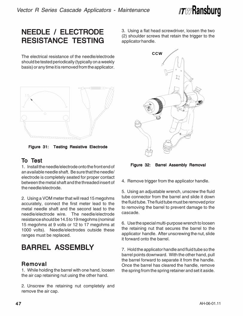
AH-06-01.11
Vector R Series Cascade Applicators - Maintenance
4747474747
NEEDLE / ELECTRODENEEDLE / ELECTRODENEEDLE / ELECTRODENEEDLE / ELECTRODENEEDLE / ELECTRODE
RESISTRESISTRESISTRESISTRESISTANCE TESTINGANCE TESTINGANCE TESTINGANCE TESTINGANCE TESTING
The electrical resistance of the needle/electrodeshould be tested periodically (typically on a weeklybasis) or any time it is removed from the applicator.
TTTTTo To To To To Testestestestest1. Install the needle/electrode onto the front end ofan available needle shaft. Be sure that the needle/electrode is completely seated for proper contactbetween the metal shaft and the threaded insert ofthe needle/electrode.
2. Using a VOM meter that will read 15 megohmsaccurately, connect the first meter lead to themetal needle shaft and the second lead to theneedle/electrode wire. The needle/electroderesistance should be 14.5 to 19 megohms (nominal15 megohms at 9 volts or 12 to 17 megohms at1000 volts). Needle/electrodes outside theseranges must be replaced.
BARRELBARRELBARRELBARRELBARREL ASSEMBL ASSEMBL ASSEMBL ASSEMBL ASSEMBLYYYYY
RemovalRemovalRemovalRemovalRemoval1. While holding the barrel with one hand, loosenthe air cap retaining nut using the other hand.
2. Unscrew the retaining nut completely andremove the air cap.
3. Using a flat head screwdriver, loosen the two(2) shoulder screws that retain the trigger to theapplicator handle.
Figure 32: Barrel Assembly RemovalFigure 32: Barrel Assembly RemovalFigure 32: Barrel Assembly RemovalFigure 32: Barrel Assembly RemovalFigure 32: Barrel Assembly Removal
4. Remove trigger from the applicator handle.
5. Using an adjustable wrench, unscrew the fluidtube connector from the barrel and slide it downthe fluid tube. The fluid tube must be removed priorto removing the barrel to prevent damage to thecascade.
6. Use the special multi-purpose wrench to loosenthe retaining nut that secures the barrel to theapplicator handle. After unscrewing the nut, slideit forward onto the barrel.
7. Hold the applicator handle and fluid tube so thebarrel points downward. With the other hand, pullthe barrel forward to separate it from the handle.Once the barrel has cleared the handle, removethe spring from the spring retainer and set it aside.
Figure 31: Testing Resistive ElectrodeFigure 31: Testing Resistive ElectrodeFigure 31: Testing Resistive ElectrodeFigure 31: Testing Resistive ElectrodeFigure 31: Testing Resistive Electrode
CCW
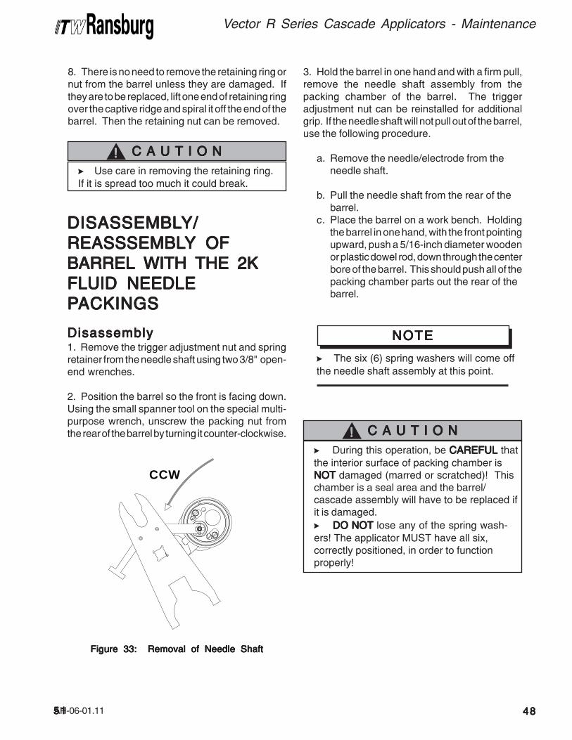
AH-06-01.115151515151
DISASSEMBLDISASSEMBLDISASSEMBLDISASSEMBLDISASSEMBLY/Y/Y/Y/Y/
REASSSEMBLREASSSEMBLREASSSEMBLREASSSEMBLREASSSEMBLYYYYY OF OF OF OF OF
BARREL WITH THE 2KBARREL WITH THE 2KBARREL WITH THE 2KBARREL WITH THE 2KBARREL WITH THE 2K
FLUID NEEDLEFLUID NEEDLEFLUID NEEDLEFLUID NEEDLEFLUID NEEDLE
PPPPPACKINGSACKINGSACKINGSACKINGSACKINGS
Figure 33: Removal of Needle ShaftFigure 33: Removal of Needle ShaftFigure 33: Removal of Needle ShaftFigure 33: Removal of Needle ShaftFigure 33: Removal of Needle Shaft
DisassemblyDisassemblyDisassemblyDisassemblyDisassembly1. Remove the trigger adjustment nut and springretainer from the needle shaft using two 3/8" open-end wrenches.
2. Position the barrel so the front is facing down.Using the small spanner tool on the special multi-purpose wrench, unscrew the packing nut fromthe rear of the barrel by turning it counter-clockwise.
CCW
3. Hold the barrel in one hand and with a firm pull,remove the needle shaft assembly from thepacking chamber of the barrel. The triggeradjustment nut can be reinstalled for additionalgrip. If the needle shaft will not pull out of the barrel,use the following procedure.
a. Remove the needle/electrode from theneedle shaft.
b. Pull the needle shaft from the rear of thebarrel.
c. Place the barrel on a work bench. Holdingthe barrel in one hand, with the front pointingupward, push a 5/16-inch diameter woodenor plastic dowel rod, down through the centerbore of the barrel. This should push all of thepacking chamber parts out the rear of thebarrel.
8. There is no need to remove the retaining ring ornut from the barrel unless they are damaged. Ifthey are to be replaced, lift one end of retaining ringover the captive ridge and spiral it off the end of thebarrel. Then the retaining nut can be removed.
>Use care in removing the retaining ring.
If it is spread too much it could break.
C A U T I O NC A U T I O NC A U T I O NC A U T I O NC A U T I O N!!!!!
>The six (6) spring washers will come off
the needle shaft assembly at this point.
NOTENOTENOTENOTENOTE
>During this operation, be CAREFULCAREFULCAREFULCAREFULCAREFUL that
the interior surface of packing chamber is
NOTNOTNOTNOTNOT damaged (marred or scratched)! Thischamber is a seal area and the barrel/cascade assembly will have to be replaced ifit is damaged.
> DO NOTDO NOTDO NOTDO NOTDO NOT lose any of the spring wash-
ers! The applicator MUST have all six,correctly positioned, in order to functionproperly!
C A U T I O NC A U T I O NC A U T I O NC A U T I O NC A U T I O N!!!!!
4848484848
Vector R Series Cascade Applicators - Maintenance
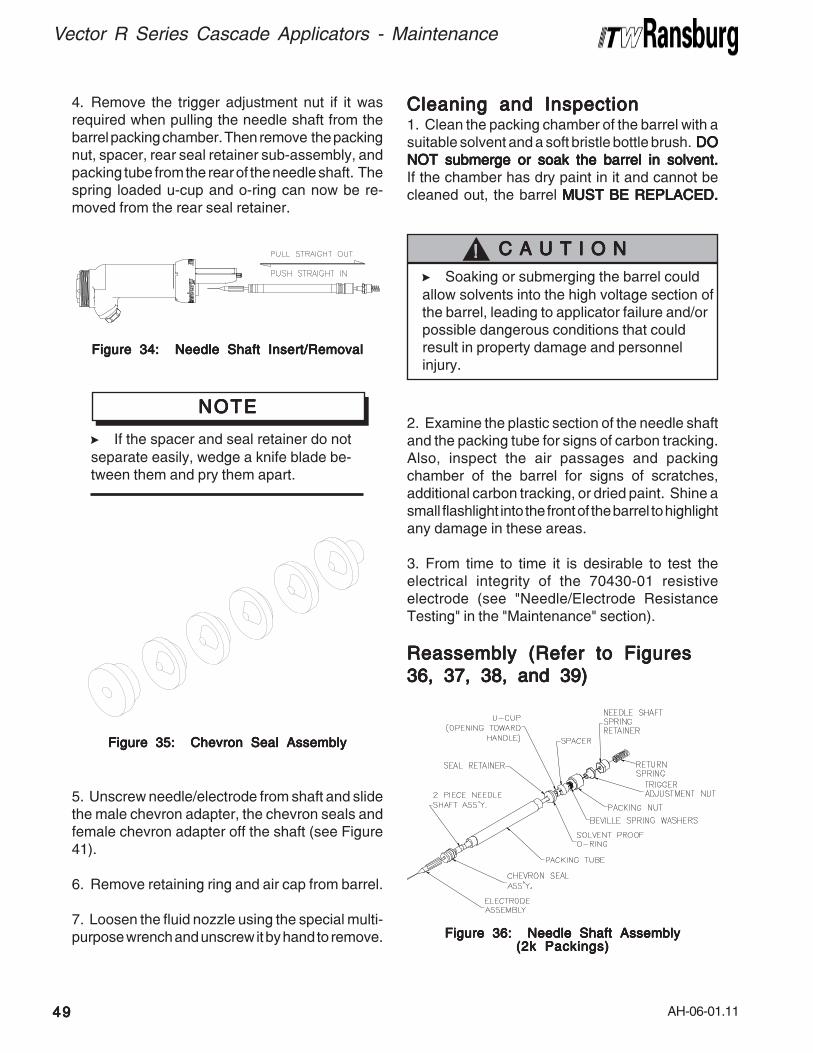
AH-06-01.11
Vector R Series Cascade Applicators - Maintenance
4949494949
Figure 36: Needle Shaft AssemblyFigure 36: Needle Shaft AssemblyFigure 36: Needle Shaft AssemblyFigure 36: Needle Shaft AssemblyFigure 36: Needle Shaft Assembly(2k Packings)(2k Packings)(2k Packings)(2k Packings)(2k Packings)
Figure 34: Needle Shaft Insert/RemovalFigure 34: Needle Shaft Insert/RemovalFigure 34: Needle Shaft Insert/RemovalFigure 34: Needle Shaft Insert/RemovalFigure 34: Needle Shaft Insert/Removal
>If the spacer and seal retainer do not
separate easily, wedge a knife blade be-tween them and pry them apart.
NOTENOTENOTENOTENOTE
Figure 35: Chevron Seal AssemblyFigure 35: Chevron Seal AssemblyFigure 35: Chevron Seal AssemblyFigure 35: Chevron Seal AssemblyFigure 35: Chevron Seal Assembly
5. Unscrew needle/electrode from shaft and slidethe male chevron adapter, the chevron seals andfemale chevron adapter off the shaft (see Figure41).
6. Remove retaining ring and air cap from barrel.
7. Loosen the fluid nozzle using the special multi-purpose wrench and unscrew it by hand to remove.
>Soaking or submerging the barrel could
allow solvents into the high voltage section ofthe barrel, leading to applicator failure and/orpossible dangerous conditions that couldresult in property damage and personnelinjury.
C A U T I O NC A U T I O NC A U T I O NC A U T I O NC A U T I O N!!!!!
4. Remove the trigger adjustment nut if it wasrequired when pulling the needle shaft from thebarrel packing chamber. Then remove the packingnut, spacer, rear seal retainer sub-assembly, andpacking tube from the rear of the needle shaft. Thespring loaded u-cup and o-ring can now be re-moved from the rear seal retainer.
Cleaning and InspectionCleaning and InspectionCleaning and InspectionCleaning and InspectionCleaning and Inspection1. Clean the packing chamber of the barrel with asuitable solvent and a soft bristle bottle brush. DODODODODO
NOT submerge or soak the barrel in solvent.NOT submerge or soak the barrel in solvent.NOT submerge or soak the barrel in solvent.NOT submerge or soak the barrel in solvent.NOT submerge or soak the barrel in solvent.If the chamber has dry paint in it and cannot becleaned out, the barrel MUST BE REPLACED.MUST BE REPLACED.MUST BE REPLACED.MUST BE REPLACED.MUST BE REPLACED.
2. Examine the plastic section of the needle shaftand the packing tube for signs of carbon tracking.Also, inspect the air passages and packingchamber of the barrel for signs of scratches,additional carbon tracking, or dried paint. Shine asmall flashlight into the front of the barrel to highlightany damage in these areas.
3. From time to time it is desirable to test theelectrical integrity of the 70430-01 resistiveelectrode (see "Needle/Electrode ResistanceTesting" in the "Maintenance" section).
Reassembly (Refer to FiguresReassembly (Refer to FiguresReassembly (Refer to FiguresReassembly (Refer to FiguresReassembly (Refer to Figures
36, 37, 38, and 39)36, 37, 38, and 39)36, 37, 38, and 39)36, 37, 38, and 39)36, 37, 38, and 39)
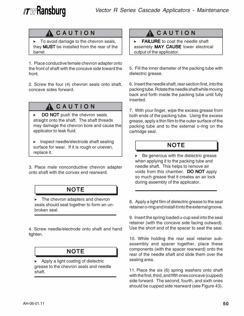
AH-06-01.11
>To avoid damage to the chevron seals,
they MUSTMUSTMUSTMUSTMUST be installed from the rear of thebarrel.
C A U T I O NC A U T I O NC A U T I O NC A U T I O NC A U T I O N!!!!!
> DO NOT DO NOT DO NOT DO NOT DO NOT push the chevron seals
straight onto the shaft. The shaft threadsmay damage the chevron bore and cause theapplicator to leak fluid.
> Inspect needle/electrode shaft sealing
surface for wear. If it is rough or uneven,replace it.
C A U T I O NC A U T I O NC A U T I O NC A U T I O NC A U T I O N!!!!!
3. Place male nonconductive chevron adapteronto shaft with the convex end rearward.
>The chevron adapters and chevron
seals should seat together to form an un-broken seal.
NOTENOTENOTENOTENOTE
4. Screw needle/electrode onto shaft and handtighten.
>Apply a light coating of dielectric
grease to the chevron seals and needleshaft.
NOTENOTENOTENOTENOTE
5. Fill the inner diameter of the packing tube withdielectric grease.
6. Insert the needle shaft, rear section first, into thepacking tube. Rotate the needle shaft while movingback and forth inside the packing tube until fullyinserted.
7. With your finger, wipe the excess grease fromboth ends of the packing tube. Using the excessgrease, apply a thin film to the outer surface of thepacking tube and to the external o-ring on thecartridge seal.
>FAILUREFAILUREFAILUREFAILUREFAILURE to coat the needle shaft
assembly MAY CAUSEMAY CAUSEMAY CAUSEMAY CAUSEMAY CAUSE lower electricaloutput of the applicator.
C A U T I O NC A U T I O NC A U T I O NC A U T I O NC A U T I O N!!!!!
Vector R Series Cascade Applicators - Maintenance
5050505050
1. Place conductive female chevron adapter ontothe front of shaft with the concave side toward thefront.
2. Screw the four (4) chevron seals onto shaft,concave sides forward.
>Be generous with the dielectric grease
when applying it to the packing tube andneedle shaft. This helps to remove airvoids from this chamber. DO NOT DO NOT DO NOT DO NOT DO NOT applyso much grease that it creates an air lockduring assembly of the applicator.
NOTENOTENOTENOTENOTE
8. Apply a light film of dielectric grease to the sealretainer o-ring and install it into the external groove.
9. Insert the spring loaded u-cup seal into the sealretainer (with the concave side facing outward).Use the short end of the spacer to seat the seal.
10. While holding the rear seal retainer sub-assembly and spacer together, place thesecomponents (with the spacer rearward) onto therear of the needle shaft and slide them over thesealing area.
11. Place the six (6) spring washers onto shaftwith the first, third, and fifth ones concave (cupped)side forward. The second, fourth, and sixth onesshould be cupped side rearward (see Figure 43).
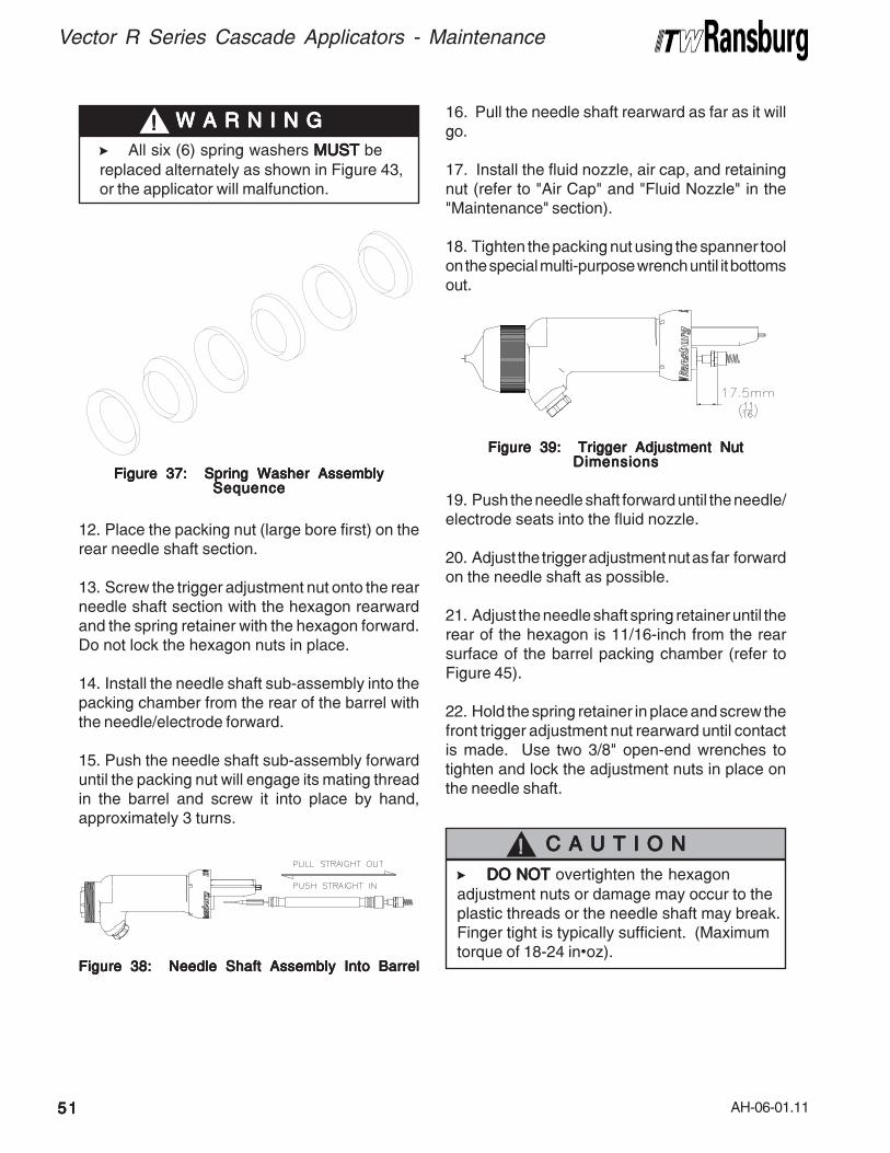
AH-06-01.11
Vector R Series Cascade Applicators - Maintenance
5151515151
> DO NOT DO NOT DO NOT DO NOT DO NOT overtighten the hexagon
adjustment nuts or damage may occur to theplastic threads or the needle shaft may break.Finger tight is typically sufficient. (Maximumtorque of 18-24 in•oz).
C A U T I O NC A U T I O NC A U T I O NC A U T I O NC A U T I O N!!!!!
Figure 39: Trigger Adjustment NutFigure 39: Trigger Adjustment NutFigure 39: Trigger Adjustment NutFigure 39: Trigger Adjustment NutFigure 39: Trigger Adjustment NutDimensionsDimensionsDimensionsDimensionsDimensions
Figure 37: Spring Washer AssemblyFigure 37: Spring Washer AssemblyFigure 37: Spring Washer AssemblyFigure 37: Spring Washer AssemblyFigure 37: Spring Washer AssemblySequenceSequenceSequenceSequenceSequence
>All six (6) spring washers MUSTMUSTMUSTMUSTMUST be
replaced alternately as shown in Figure 43,or the applicator will malfunction.
W A R N I N GW A R N I N GW A R N I N GW A R N I N GW A R N I N G!!!!!
12. Place the packing nut (large bore first) on therear needle shaft section.
13. Screw the trigger adjustment nut onto the rearneedle shaft section with the hexagon rearwardand the spring retainer with the hexagon forward.Do not lock the hexagon nuts in place.
14. Install the needle shaft sub-assembly into thepacking chamber from the rear of the barrel withthe needle/electrode forward.
15. Push the needle shaft sub-assembly forwarduntil the packing nut will engage its mating threadin the barrel and screw it into place by hand,approximately 3 turns.
16. Pull the needle shaft rearward as far as it willgo.
17. Install the fluid nozzle, air cap, and retainingnut (refer to "Air Cap" and "Fluid Nozzle" in the"Maintenance" section).
18. Tighten the packing nut using the spanner toolon the special multi-purpose wrench until it bottomsout.
Figure 38: Needle Shaft Assembly Into BarrelFigure 38: Needle Shaft Assembly Into BarrelFigure 38: Needle Shaft Assembly Into BarrelFigure 38: Needle Shaft Assembly Into BarrelFigure 38: Needle Shaft Assembly Into Barrel
19. Push the needle shaft forward until the needle/electrode seats into the fluid nozzle.
20. Adjust the trigger adjustment nut as far forwardon the needle shaft as possible.
21. Adjust the needle shaft spring retainer until therear of the hexagon is 11/16-inch from the rearsurface of the barrel packing chamber (refer toFigure 45).
22. Hold the spring retainer in place and screw thefront trigger adjustment nut rearward until contactis made. Use two 3/8" open-end wrenches totighten and lock the adjustment nuts in place onthe needle shaft.
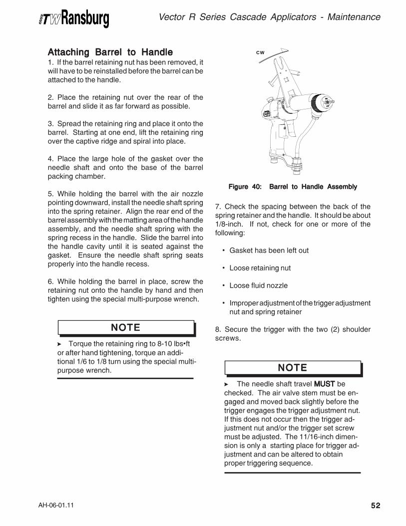
AH-06-01.11
Attaching Barrel to HandleAttaching Barrel to HandleAttaching Barrel to HandleAttaching Barrel to HandleAttaching Barrel to Handle1. If the barrel retaining nut has been removed, itwill have to be reinstalled before the barrel can beattached to the handle.
2. Place the retaining nut over the rear of thebarrel and slide it as far forward as possible.
3. Spread the retaining ring and place it onto thebarrel. Starting at one end, lift the retaining ringover the captive ridge and spiral into place.
4. Place the large hole of the gasket over theneedle shaft and onto the base of the barrelpacking chamber.
5. While holding the barrel with the air nozzlepointing downward, install the needle shaft springinto the spring retainer. Align the rear end of thebarrel assembly with the matting area of the handleassembly, and the needle shaft spring with thespring recess in the handle. Slide the barrel intothe handle cavity until it is seated against thegasket. Ensure the needle shaft spring seatsproperly into the handle recess.
6. While holding the barrel in place, screw theretaining nut onto the handle by hand and thentighten using the special multi-purpose wrench.
>Torque the retaining ring to 8-10 lbs•ft
or after hand tightening, torque an addi-tional 1/6 to 1/8 turn using the special multi-purpose wrench.
NOTENOTENOTENOTENOTE
CW
Figure 40: Barrel to Handle AssemblyFigure 40: Barrel to Handle AssemblyFigure 40: Barrel to Handle AssemblyFigure 40: Barrel to Handle AssemblyFigure 40: Barrel to Handle Assembly
Vector R Series Cascade Applicators - Maintenance
5252525252
7. Check the spacing between the back of thespring retainer and the handle. It should be about1/8-inch. If not, check for one or more of thefollowing:
• Gasket has been left out
• Loose retaining nut
• Loose fluid nozzle
• Improper adjustment of the trigger adjustmentnut and spring retainer
8. Secure the trigger with the two (2) shoulderscrews.
>The needle shaft travel MUST MUST MUST MUST MUST be
checked. The air valve stem must be en-gaged and moved back slightly before thetrigger engages the trigger adjustment nut.If this does not occur then the trigger ad-justment nut and/or the trigger set screwmust be adjusted. The 11/16-inch dimen-sion is only a starting place for trigger ad-justment and can be altered to obtainproper triggering sequence.
NOTENOTENOTENOTENOTE
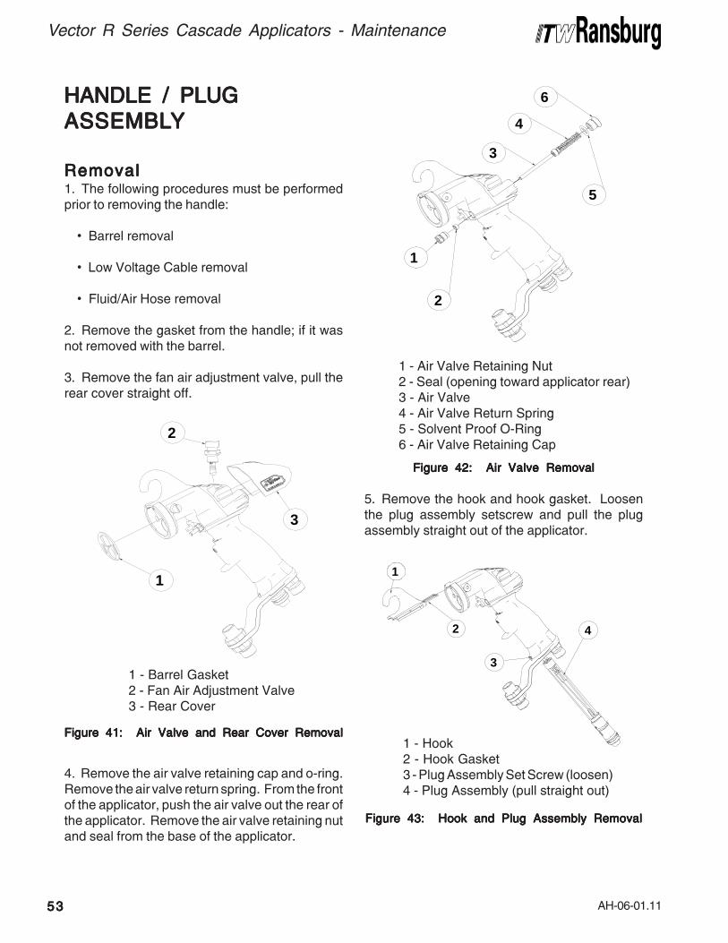
AH-06-01.11
Vector R Series Cascade Applicators - Maintenance
5353535353
1
2
3
4
Figure 43: Hook and Plug Assembly RemovalFigure 43: Hook and Plug Assembly RemovalFigure 43: Hook and Plug Assembly RemovalFigure 43: Hook and Plug Assembly RemovalFigure 43: Hook and Plug Assembly Removal
5. Remove the hook and hook gasket. Loosenthe plug assembly setscrew and pull the plugassembly straight out of the applicator.
HANDLE / PLUGHANDLE / PLUGHANDLE / PLUGHANDLE / PLUGHANDLE / PLUG
ASSEMBLASSEMBLASSEMBLASSEMBLASSEMBLYYYYY
RemovalRemovalRemovalRemovalRemoval1. The following procedures must be performedprior to removing the handle:
• Barrel removal
• Low Voltage Cable removal
• Fluid/Air Hose removal
2. Remove the gasket from the handle; if it wasnot removed with the barrel.
3. Remove the fan air adjustment valve, pull therear cover straight off.
Figure 41: Air Valve and Rear Cover RemovalFigure 41: Air Valve and Rear Cover RemovalFigure 41: Air Valve and Rear Cover RemovalFigure 41: Air Valve and Rear Cover RemovalFigure 41: Air Valve and Rear Cover Removal
4. Remove the air valve retaining cap and o-ring.Remove the air valve return spring. From the frontof the applicator, push the air valve out the rear ofthe applicator. Remove the air valve retaining nutand seal from the base of the applicator.
Figure 42: Air Valve RemovalFigure 42: Air Valve RemovalFigure 42: Air Valve RemovalFigure 42: Air Valve RemovalFigure 42: Air Valve Removal
1
2
3
1
2
3
4
6
5
1 - Barrel Gasket2 - Fan Air Adjustment Valve3 - Rear Cover
1 - Air Valve Retaining Nut2 - Seal (opening toward applicator rear)3 - Air Valve4 - Air Valve Return Spring5 - Solvent Proof O-Ring6 - Air Valve Retaining Cap
1 - Hook2 - Hook Gasket3 - Plug Assembly Set Screw (loosen)4 - Plug Assembly (pull straight out)
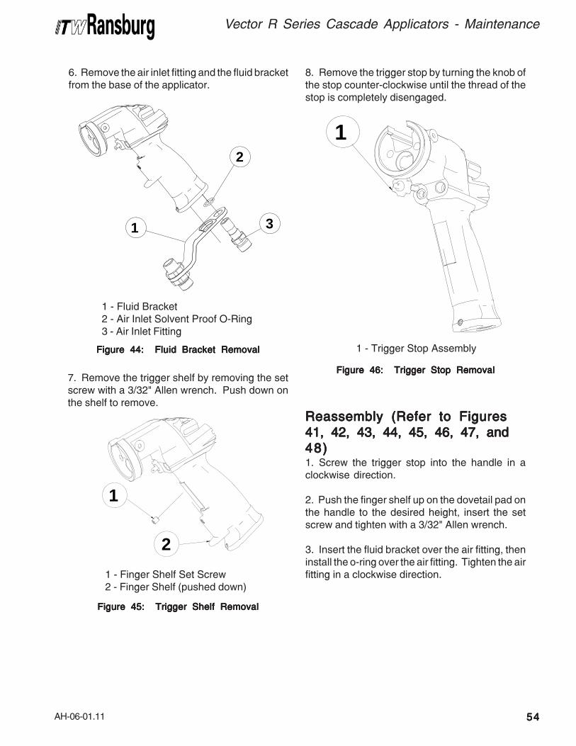
AH-06-01.11
Figure 44: Fluid Bracket RemovalFigure 44: Fluid Bracket RemovalFigure 44: Fluid Bracket RemovalFigure 44: Fluid Bracket RemovalFigure 44: Fluid Bracket Removal
Figure 45: Trigger Shelf RemovalFigure 45: Trigger Shelf RemovalFigure 45: Trigger Shelf RemovalFigure 45: Trigger Shelf RemovalFigure 45: Trigger Shelf Removal
1
2
Figure 46: Trigger Stop RemovalFigure 46: Trigger Stop RemovalFigure 46: Trigger Stop RemovalFigure 46: Trigger Stop RemovalFigure 46: Trigger Stop Removal
1
1
2
3
6. Remove the air inlet fitting and the fluid bracketfrom the base of the applicator.
7. Remove the trigger shelf by removing the setscrew with a 3/32" Allen wrench. Push down onthe shelf to remove.
8. Remove the trigger stop by turning the knob ofthe stop counter-clockwise until the thread of thestop is completely disengaged.
Vector R Series Cascade Applicators - Maintenance
5454545454
1 - Fluid Bracket2 - Air Inlet Solvent Proof O-Ring3 - Air Inlet Fitting
1 - Finger Shelf Set Screw2 - Finger Shelf (pushed down)
1 - Trigger Stop Assembly
Reassembly (Refer to FiguresReassembly (Refer to FiguresReassembly (Refer to FiguresReassembly (Refer to FiguresReassembly (Refer to Figures
41, 42, 43, 44, 45, 46, 47, and41, 42, 43, 44, 45, 46, 47, and41, 42, 43, 44, 45, 46, 47, and41, 42, 43, 44, 45, 46, 47, and41, 42, 43, 44, 45, 46, 47, and
48)48)48)48)48)1. Screw the trigger stop into the handle in aclockwise direction.
2. Push the finger shelf up on the dovetail pad onthe handle to the desired height, insert the setscrew and tighten with a 3/32" Allen wrench.
3. Insert the fluid bracket over the air fitting, theninstall the o-ring over the air fitting. Tighten the airfitting in a clockwise direction.
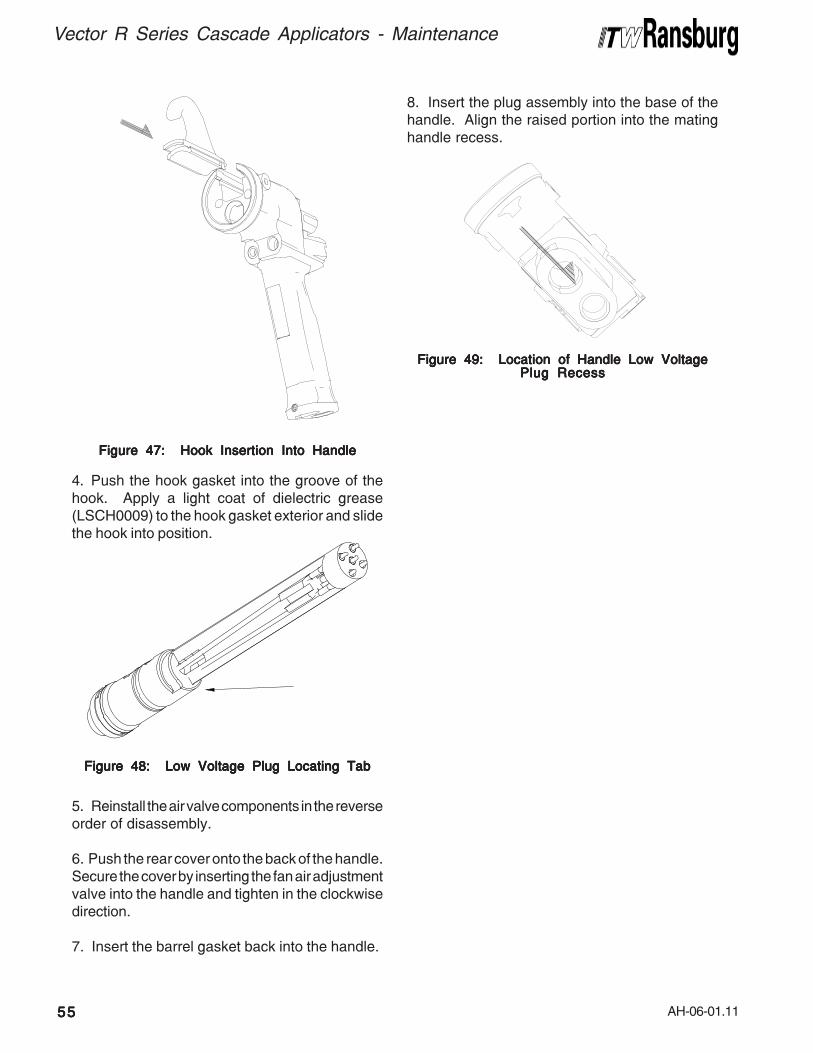
AH-06-01.11
Vector R Series Cascade Applicators - Maintenance
5555555555
Figure 47: Hook Insertion Into HandleFigure 47: Hook Insertion Into HandleFigure 47: Hook Insertion Into HandleFigure 47: Hook Insertion Into HandleFigure 47: Hook Insertion Into Handle
4. Push the hook gasket into the groove of thehook. Apply a light coat of dielectric grease(LSCH0009) to the hook gasket exterior and slidethe hook into position.
Figure 48: Low Voltage Plug Locating TabFigure 48: Low Voltage Plug Locating TabFigure 48: Low Voltage Plug Locating TabFigure 48: Low Voltage Plug Locating TabFigure 48: Low Voltage Plug Locating Tab
5. Reinstall the air valve components in the reverseorder of disassembly.
6. Push the rear cover onto the back of the handle.Secure the cover by inserting the fan air adjustmentvalve into the handle and tighten in the clockwisedirection.
7. Insert the barrel gasket back into the handle.
8. Insert the plug assembly into the base of thehandle. Align the raised portion into the matinghandle recess.
Figure 49: Location of Handle Low VoltageFigure 49: Location of Handle Low VoltageFigure 49: Location of Handle Low VoltageFigure 49: Location of Handle Low VoltageFigure 49: Location of Handle Low VoltagePlug RecessPlug RecessPlug RecessPlug RecessPlug Recess
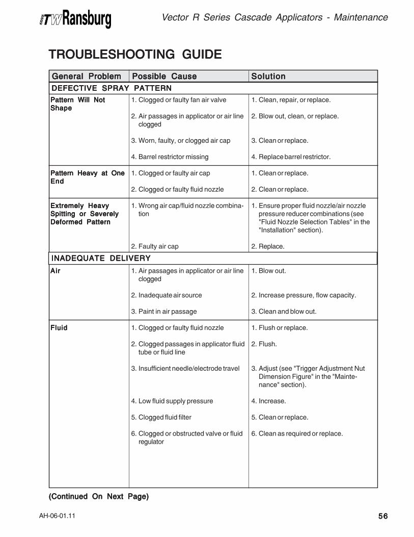
AH-06-01.11
TROUBLESHOOTING GUIDETROUBLESHOOTING GUIDETROUBLESHOOTING GUIDETROUBLESHOOTING GUIDETROUBLESHOOTING GUIDE
Pattern Will NotPattern Will NotPattern Will NotPattern Will NotPattern Will Not
ShapeShapeShapeShapeShape
Pattern Heavy at OnePattern Heavy at OnePattern Heavy at OnePattern Heavy at OnePattern Heavy at One
EndEndEndEndEnd
Extremely HeavyExtremely HeavyExtremely HeavyExtremely HeavyExtremely Heavy
Spitting or SeverelySpitting or SeverelySpitting or SeverelySpitting or SeverelySpitting or Severely
Deformed PatternDeformed PatternDeformed PatternDeformed PatternDeformed Pattern
AirAirAirAirAir
FluidFluidFluidFluidFluid
1. Clogged or faulty fan air valve
2. Air passages in applicator or air lineclogged
3. Worn, faulty, or clogged air cap
4. Barrel restrictor missing
1. Clogged or faulty air cap
2. Clogged or faulty fluid nozzle
1. Wrong air cap/fluid nozzle combina-tion
2. Faulty air cap
1. Air passages in applicator or air lineclogged
2. Inadequate air source
3. Paint in air passage
1. Clogged or faulty fluid nozzle
2. Clogged passages in applicator fluidtube or fluid line
3. Insufficient needle/electrode travel
4. Low fluid supply pressure
5. Clogged fluid filter
6. Clogged or obstructed valve or fluidregulator
1. Clean, repair, or replace.
2. Blow out, clean, or replace.
3. Clean or replace.
4. Replace barrel restrictor.
1. Clean or replace.
2. Clean or replace.
1. Ensure proper fluid nozzle/air nozzlepressure reducer combinations (see"Fluid Nozzle Selection Tables" in the"Installation" section).
2. Replace.
1. Blow out.
2. Increase pressure, flow capacity.
3. Clean and blow out.
1. Flush or replace.
2. Flush.
3. Adjust (see "Trigger Adjustment NutDimension Figure" in the "Mainte-nance" section).
4. Increase.
5. Clean or replace.
6. Clean as required or replace.
General ProblemGeneral ProblemGeneral ProblemGeneral ProblemGeneral Problem Possible CausePossible CausePossible CausePossible CausePossible Cause SolutionSolutionSolutionSolutionSolution
DEFECTIVE SPRAY PATTERNDEFECTIVE SPRAY PATTERNDEFECTIVE SPRAY PATTERNDEFECTIVE SPRAY PATTERNDEFECTIVE SPRAY PATTERN
INADEQUATE DELIVERYINADEQUATE DELIVERYINADEQUATE DELIVERYINADEQUATE DELIVERYINADEQUATE DELIVERY
(Continued On Next Page)(Continued On Next Page)(Continued On Next Page)(Continued On Next Page)(Continued On Next Page)
Vector R Series Cascade Applicators - Maintenance
5656565656
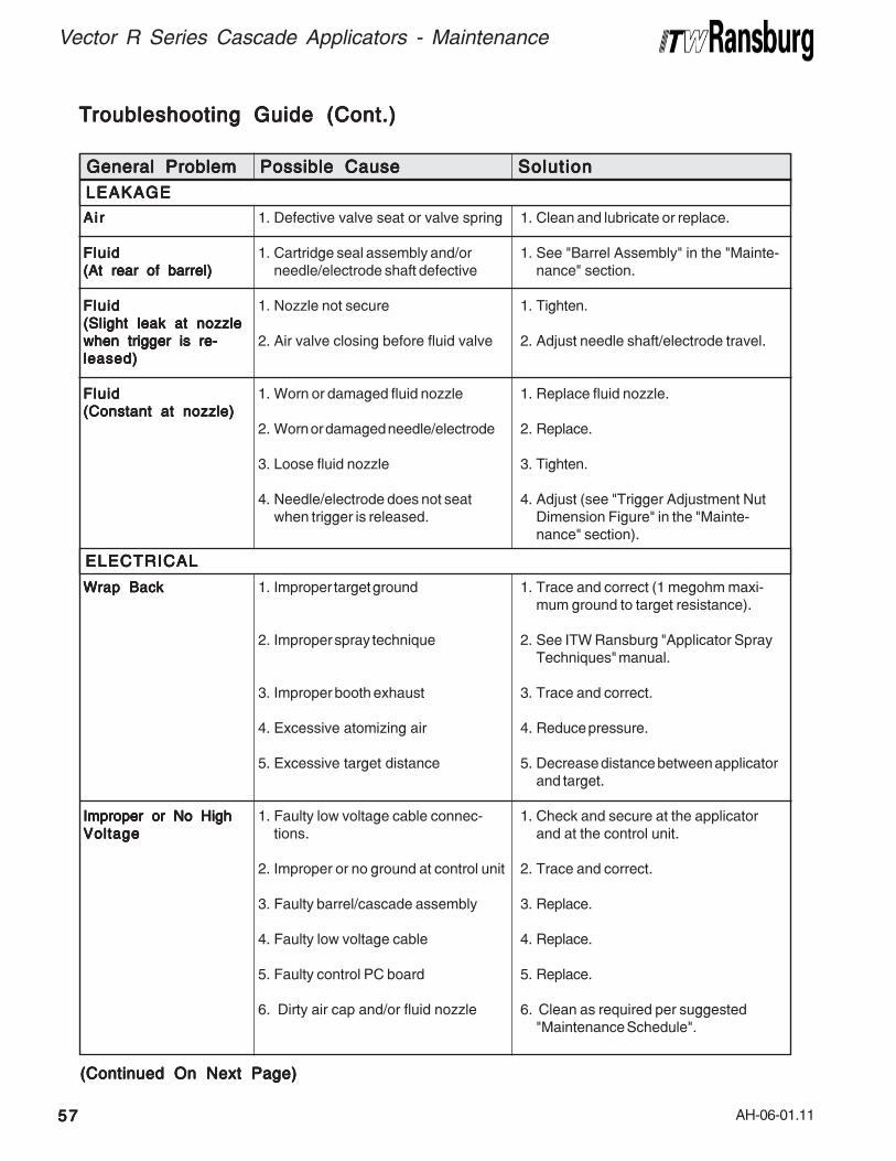
AH-06-01.11
Vector R Series Cascade Applicators - Maintenance
5757575757
General ProblemGeneral ProblemGeneral ProblemGeneral ProblemGeneral Problem Possible CausePossible CausePossible CausePossible CausePossible Cause SolutionSolutionSolutionSolutionSolution
LEAKAGELEAKAGELEAKAGELEAKAGELEAKAGE
ELECTRICALELECTRICALELECTRICALELECTRICALELECTRICAL
AirAirAirAirAir
FluidFluidFluidFluidFluid
(At rear of barrel)(At rear of barrel)(At rear of barrel)(At rear of barrel)(At rear of barrel)
FluidFluidFluidFluidFluid
(Slight leak at nozzle(Slight leak at nozzle(Slight leak at nozzle(Slight leak at nozzle(Slight leak at nozzle
when trigger is re-when trigger is re-when trigger is re-when trigger is re-when trigger is re-
leased)leased)leased)leased)leased)
FluidFluidFluidFluidFluid
(Constant at nozzle)(Constant at nozzle)(Constant at nozzle)(Constant at nozzle)(Constant at nozzle)
Wrap BackWrap BackWrap BackWrap BackWrap Back
Improper or No HighImproper or No HighImproper or No HighImproper or No HighImproper or No High
VoltageVoltageVoltageVoltageVoltage
1. Defective valve seat or valve spring
1. Cartridge seal assembly and/orneedle/electrode shaft defective
1. Nozzle not secure
2. Air valve closing before fluid valve
1. Worn or damaged fluid nozzle
2. Worn or damaged needle/electrode
3. Loose fluid nozzle
4. Needle/electrode does not seatwhen trigger is released.
1. Improper target ground
2. Improper spray technique
3. Improper booth exhaust
4. Excessive atomizing air
5. Excessive target distance
1. Faulty low voltage cable connec-tions.
2. Improper or no ground at control unit
3. Faulty barrel/cascade assembly
4. Faulty low voltage cable
5. Faulty control PC board
6. Dirty air cap and/or fluid nozzle
1. Clean and lubricate or replace.
1. See "Barrel Assembly" in the "Mainte-nance" section.
1. Tighten.
2. Adjust needle shaft/electrode travel.
1. Replace fluid nozzle.
2. Replace.
3. Tighten.
4. Adjust (see "Trigger Adjustment NutDimension Figure" in the "Mainte-nance" section).
1. Trace and correct (1 megohm maxi-mum ground to target resistance).
2. See ITW Ransburg "Applicator SprayTechniques" manual.
3. Trace and correct.
4. Reduce pressure.
5. Decrease distance between applicatorand target.
1. Check and secure at the applicatorand at the control unit.
2. Trace and correct.
3. Replace.
4. Replace.
5. Replace.
6. Clean as required per suggested"Maintenance Schedule".
TTTTTroubleshooting Guide (Cont.)roubleshooting Guide (Cont.)roubleshooting Guide (Cont.)roubleshooting Guide (Cont.)roubleshooting Guide (Cont.)
(Continued On Next Page)(Continued On Next Page)(Continued On Next Page)(Continued On Next Page)(Continued On Next Page)

AH-06-01.11
General ProblemGeneral ProblemGeneral ProblemGeneral ProblemGeneral Problem Possible CausePossible CausePossible CausePossible CausePossible Cause SolutionSolutionSolutionSolutionSolution
ELECTRICAL (CELECTRICAL (CELECTRICAL (CELECTRICAL (CELECTRICAL (Continued)ontinued)ontinued)ontinued)ontinued)
Improper or No HighImproper or No HighImproper or No HighImproper or No HighImproper or No High
Voltage (Continued)Voltage (Continued)Voltage (Continued)Voltage (Continued)Voltage (Continued)
Isolation SystemIsolation SystemIsolation SystemIsolation SystemIsolation System
Grounded OutGrounded OutGrounded OutGrounded OutGrounded Out
7. Blown fuse
8. Is the power turned on?
9. Is the atomizing air turned on?
10. Is the applicator triggered?
11. Is the applicator switch on?
12. Is the paint too conductive?
13. Faulty flow switch
1. Failed fluid hose
2. Isolation stand or charged equip-ment too close to ground
7. Replace fuse.
8. Check power supply.
9. Check air regulator.
10. Check applicator trigger.
11. Check applictor switch.
12. Check conductivity of paint.
13. Replace flow switch.
1. Replace fluid hose.
2. Provide adequate ground distance.
TTTTTroubleshooting Guide (Cont.)roubleshooting Guide (Cont.)roubleshooting Guide (Cont.)roubleshooting Guide (Cont.)roubleshooting Guide (Cont.)
Vector R Series Cascade Applicators - Maintenance
5858585858

AH-06-01.11
Vector R Series Cascade Applicators - Maintenance
5959595959
NOTESNOTESNOTESNOTESNOTES

AH-06-01.11
PPPPPARARARARARTS IDENTIFICATS IDENTIFICATS IDENTIFICATS IDENTIFICATS IDENTIFICATIONTIONTIONTIONTION
46
21
19
22
17
45
11
1
5
78
910
40
39
38
36
37
20
2827
33
34
30
31 3143 42
4441
18
25
2324
12
26
1514
32
29
13
35
4
Figure 50: R90/70 Cascade Solventborne Applicator BreakdownFigure 50: R90/70 Cascade Solventborne Applicator BreakdownFigure 50: R90/70 Cascade Solventborne Applicator BreakdownFigure 50: R90/70 Cascade Solventborne Applicator BreakdownFigure 50: R90/70 Cascade Solventborne Applicator Breakdown
Vector R Series Cascade Applicators - Parts Identification
6060606060
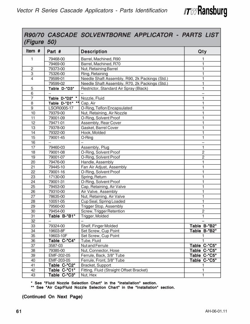
AH-06-01.11
Vector R Series Cascade Applicators - Parts Identification
* See "Fluid Nozzle Selection Chart" in the "Installation" section.* See "Fluid Nozzle Selection Chart" in the "Installation" section.* See "Fluid Nozzle Selection Chart" in the "Installation" section.* See "Fluid Nozzle Selection Chart" in the "Installation" section.* See "Fluid Nozzle Selection Chart" in the "Installation" section.
** See "Air Cap/Fluid Nozzle Selection Chart" in the "Installation" section.** See "Air Cap/Fluid Nozzle Selection Chart" in the "Installation" section.** See "Air Cap/Fluid Nozzle Selection Chart" in the "Installation" section.** See "Air Cap/Fluid Nozzle Selection Chart" in the "Installation" section.** See "Air Cap/Fluid Nozzle Selection Chart" in the "Installation" section.
(Continued On Next Page)(Continued On Next Page)(Continued On Next Page)(Continued On Next Page)(Continued On Next Page)
1 79468-00 Barrel, Machined, R90 179469-00 Barrel, Machined, R70 1
2 79373-00 Nut, Retaining Barrel 13 75326-00 Ring, Retaining 14 79599-01 Needle Shaft Assembly, R90, 2k Packings (Std.) 1
79599-02 Needle Shaft Assembly, R70, 2k Packings (Std.) 15 Table D-"D3"Table D-"D3"Table D-"D3"Table D-"D3"Table D-"D3" Restrictor, Standard Air Spray (Black) 16 -- -- --7 Table D-"D2"Table D-"D2"Table D-"D2"Table D-"D2"Table D-"D2" ***** Nozzle, Fluid 18 Table D-"D1"Table D-"D1"Table D-"D1"Table D-"D1"Table D-"D1" ** ** ** ** ** Cap, Air 19 LSOR0005-17 O-Ring, Teflon Encapsulated 110 79379-00 Nut, Retaining, Air Nozzle 111 79001-09 O-Ring, Solvent Proof 112 79471-01 Assembly, Rear Cover 113 79378-00 Gasket, Barrel Cover 114 79322-00 Hook, Molded 115 79001-45 O-Ring 116 -- -- --17 79460-03 Assembly, Plug 118 79001-08 O-Ring, Solvent Proof 219 79001-07 O-Ring, Solvent Proof 220 79476-00 Handle, Assembly 121 79445-10 Fan Air Adjust, Assembly 122 79001-16 O-Ring, Solvent Proof 123 17130-00 Spring, Return 124 79001-31 O-Ring, Solvent Proof 125 79453-00 Cap, Retaining, Air Valve 126 79310-00 Air Valve, Assembly 127 78635-00 Nut, Retaining, Air Valve 128 10051-05 Cup Seal, Spring Loaded 129 79560-00 Trigger Stop, Assembly 130 79454-00 Screw, Trigger Retention 231 Table B-"B1"Table B-"B1"Table B-"B1"Table B-"B1"Table B-"B1" Trigger, Molded 132 -- -- --33 79324-00 Shelf, Finger Molded Table B-"B2"Table B-"B2"Table B-"B2"Table B-"B2"Table B-"B2"34 19603-8F Set Screw, Cup Point Table B-"B2"Table B-"B2"Table B-"B2"Table B-"B2"Table B-"B2"35 19603-10F Set Screw, Cup Point 136 Table C-"C4"Table C-"C4"Table C-"C4"Table C-"C4"Table C-"C4" Tube, Fluid 137 3587-03 Nut and Ferrule Table C-"C5"Table C-"C5"Table C-"C5"Table C-"C5"Table C-"C5"38 79385-00 Nut, Connector, Hose Table C-"C5"Table C-"C5"Table C-"C5"Table C-"C5"Table C-"C5"39 EMF-202-05 Ferrule, Back, 3/8" Tube Table C-"C5"Table C-"C5"Table C-"C5"Table C-"C5"Table C-"C5"40 EMF-203-05 Ferrule, Front, 3/8" Tube Table C-"C5"Table C-"C5"Table C-"C5"Table C-"C5"Table C-"C5"41 Table C-"C2"Table C-"C2"Table C-"C2"Table C-"C2"Table C-"C2" Bracket, Support 142 Table C-"C1"Table C-"C1"Table C-"C1"Table C-"C1"Table C-"C1" Fitting, Fluid (Straight Offset Bracket) 143 Table C-"C3"Table C-"C3"Table C-"C3"Table C-"C3"Table C-"C3" Nut, Hex 1
Item #Item #Item #Item #Item #
R90/70 CASCADE SOLR90/70 CASCADE SOLR90/70 CASCADE SOLR90/70 CASCADE SOLR90/70 CASCADE SOLVENTBORNE APPLICAVENTBORNE APPLICAVENTBORNE APPLICAVENTBORNE APPLICAVENTBORNE APPLICATTTTTOR - POR - POR - POR - POR - PARARARARARTS LISTTS LISTTS LISTTS LISTTS LIST(Figure 50)(Figure 50)(Figure 50)(Figure 50)(Figure 50)
Part #Part #Part #Part #Part # DescriptionDescriptionDescriptionDescriptionDescription Q t yQ t yQ t yQ t yQ t y
6161616161
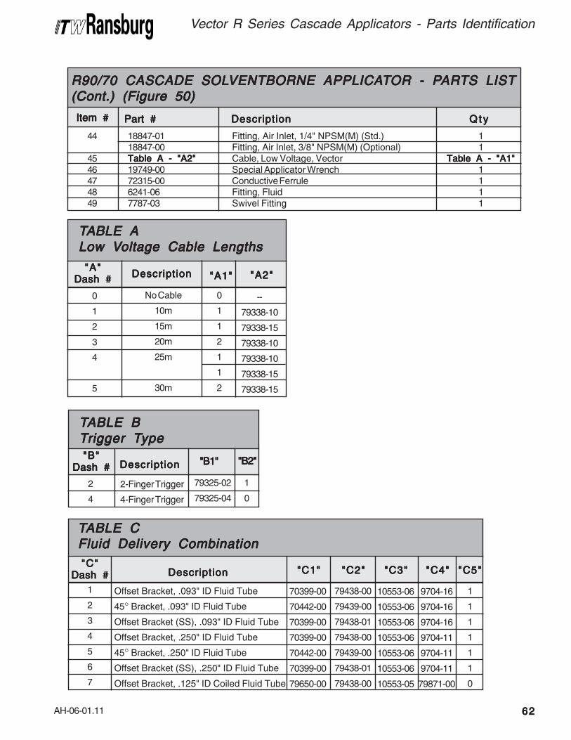
AH-06-01.11
Vector R Series Cascade Applicators - Parts Identification
6262626262
44 18847-01 Fitting, Air Inlet, 1/4" NPSM(M) (Std.) 118847-00 Fitting, Air Inlet, 3/8" NPSM(M) (Optional) 1
45 Table A - "A2"Table A - "A2"Table A - "A2"Table A - "A2"Table A - "A2" Cable, Low Voltage, Vector Table A - "A1"Table A - "A1"Table A - "A1"Table A - "A1"Table A - "A1"46 19749-00 Special Applicator Wrench 147 72315-00 Conductive Ferrule 148 6241-06 Fitting, Fluid 149 7787-03 Swivel Fitting 1
Item #Item #Item #Item #Item #
R90/70 CASCADE SOLR90/70 CASCADE SOLR90/70 CASCADE SOLR90/70 CASCADE SOLR90/70 CASCADE SOLVENTBORNE APPLICAVENTBORNE APPLICAVENTBORNE APPLICAVENTBORNE APPLICAVENTBORNE APPLICATTTTTOR - POR - POR - POR - POR - PARARARARARTS LISTTS LISTTS LISTTS LISTTS LIST(Cont.) (Figure 50)(Cont.) (Figure 50)(Cont.) (Figure 50)(Cont.) (Figure 50)(Cont.) (Figure 50)
Part #Part #Part #Part #Part # DescriptionDescriptionDescriptionDescriptionDescription Q t yQ t yQ t yQ t yQ t y
No Cable
10m
15m
20m
25m
30m
TTTTTABLE AABLE AABLE AABLE AABLE ALow VLow VLow VLow VLow Voltage Cable Lengthsoltage Cable Lengthsoltage Cable Lengthsoltage Cable Lengthsoltage Cable Lengths
--
79338-10
79338-15
79338-10
79338-10
79338-15
79338-15
"A2""A2""A2""A2""A2"DescriptionDescriptionDescriptionDescriptionDescription
0
1
1
2
1
1
2
"A1""A1""A1""A1""A1""A""A""A""A""A"
Dash #Dash #Dash #Dash #Dash #
0
1
2
3
4
5
2-Finger Trigger
4-Finger Trigger
79325-02
79325-04
"B1""B1""B1""B1""B1"DescriptionDescriptionDescriptionDescriptionDescription
2
4
"B""B""B""B""B"Dash #Dash #Dash #Dash #Dash #
TTTTTABLE BABLE BABLE BABLE BABLE BTTTTTrigger Trigger Trigger Trigger Trigger Typeypeypeypeype
"B2""B2""B2""B2""B2"
1
0
1
2
3
4
5
6
7
Offset Bracket, .093" ID Fluid Tube
45° Bracket, .093" ID Fluid Tube
Offset Bracket (SS), .093" ID Fluid Tube
Offset Bracket, .250" ID Fluid Tube
45° Bracket, .250" ID Fluid Tube
Offset Bracket (SS), .250" ID Fluid Tube
Offset Bracket, .125" ID Coiled Fluid Tube
70399-00
70442-00
70399-00
70399-00
70442-00
70399-00
79650-00
"C1""C1""C1""C1""C1"DescriptionDescriptionDescriptionDescriptionDescription"C""C""C""C""C"
Dash #Dash #Dash #Dash #Dash #
TTTTTABLE CABLE CABLE CABLE CABLE CFluid Delivery CombinationFluid Delivery CombinationFluid Delivery CombinationFluid Delivery CombinationFluid Delivery Combination
79438-00
79439-00
79438-01
79438-00
79439-00
79438-01
79438-00
"C2""C2""C2""C2""C2"
10553-06
10553-06
10553-06
10553-06
10553-06
10553-06
10553-05
"C3""C3""C3""C3""C3"
9704-16
9704-16
9704-16
9704-11
9704-11
9704-11
79871-00
"C4""C4""C4""C4""C4"
1
1
1
1
1
1
0
"C5""C5""C5""C5""C5"
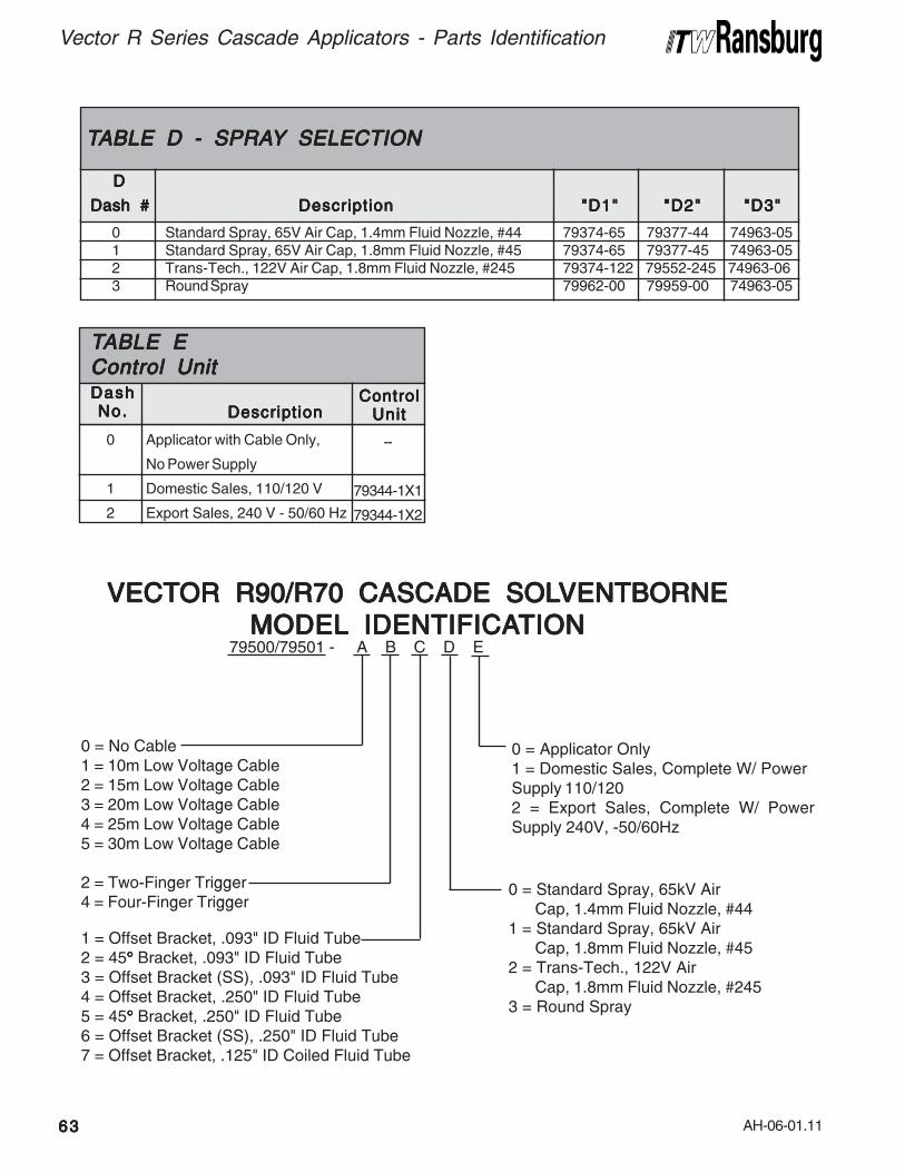
AH-06-01.11
Vector R Series Cascade Applicators - Parts Identification
6363636363
Applicator with Cable Only,
No Power Supply
Domestic Sales, 110/120 V
Export Sales, 240 V - 50/60 Hz
--
79344-1X1
79344-1X2
ControlControlControlControlControlUnitUnitUnitUnitUnitDescriptionDescriptionDescriptionDescriptionDescription
0
1
2
DashDashDashDashDashNo.No.No.No.No.
TTTTTABLE EABLE EABLE EABLE EABLE EControl UnitControl UnitControl UnitControl UnitControl Unit
0 Standard Spray, 65V Air Cap, 1.4mm Fluid Nozzle, #441 Standard Spray, 65V Air Cap, 1.8mm Fluid Nozzle, #452 Trans-Tech., 122V Air Cap, 1.8mm Fluid Nozzle, #2453 Round Spray
DDDDD
Dash #Dash #Dash #Dash #Dash #
TTTTTABLE D - SPRAABLE D - SPRAABLE D - SPRAABLE D - SPRAABLE D - SPRAYYYYY SELECTION SELECTION SELECTION SELECTION SELECTION
"D1""D1""D1""D1""D1"DescriptionDescriptionDescriptionDescriptionDescription "D2""D2""D2""D2""D2" "D3""D3""D3""D3""D3"
79374-65 79377-44 74963-0579374-65 79377-45 74963-0579374-122 79552-245 74963-0679962-00 79959-00 74963-05
1 = Offset Bracket, .093" ID Fluid Tube2 = 45°°°°° Bracket, .093" ID Fluid Tube3 = Offset Bracket (SS), .093" ID Fluid Tube4 = Offset Bracket, .250" ID Fluid Tube5 = 45°°°°° Bracket, .250" ID Fluid Tube6 = Offset Bracket (SS), .250" ID Fluid Tube7 = Offset Bracket, .125" ID Coiled Fluid Tube
79500/79501 - A B C D E
0 = No Cable1 = 10m Low Voltage Cable2 = 15m Low Voltage Cable3 = 20m Low Voltage Cable4 = 25m Low Voltage Cable5 = 30m Low Voltage Cable
2 = Two-Finger Trigger4 = Four-Finger Trigger
0 = Standard Spray, 65kV AirCap, 1.4mm Fluid Nozzle, #44
1 = Standard Spray, 65kV AirCap, 1.8mm Fluid Nozzle, #45
2 = Trans-Tech., 122V AirCap, 1.8mm Fluid Nozzle, #245
3 = Round Spray
0 = Applicator Only1 = Domestic Sales, Complete W/ PowerSupply 110/1202 = Export Sales, Complete W/ PowerSupply 240V, -50/60Hz
VECTVECTVECTVECTVECTOR R90/R70 CASCADE SOLOR R90/R70 CASCADE SOLOR R90/R70 CASCADE SOLOR R90/R70 CASCADE SOLOR R90/R70 CASCADE SOLVENTBORNEVENTBORNEVENTBORNEVENTBORNEVENTBORNE
MODELMODELMODELMODELMODEL IDENTIFICA IDENTIFICA IDENTIFICA IDENTIFICA IDENTIFICATIONTIONTIONTIONTION
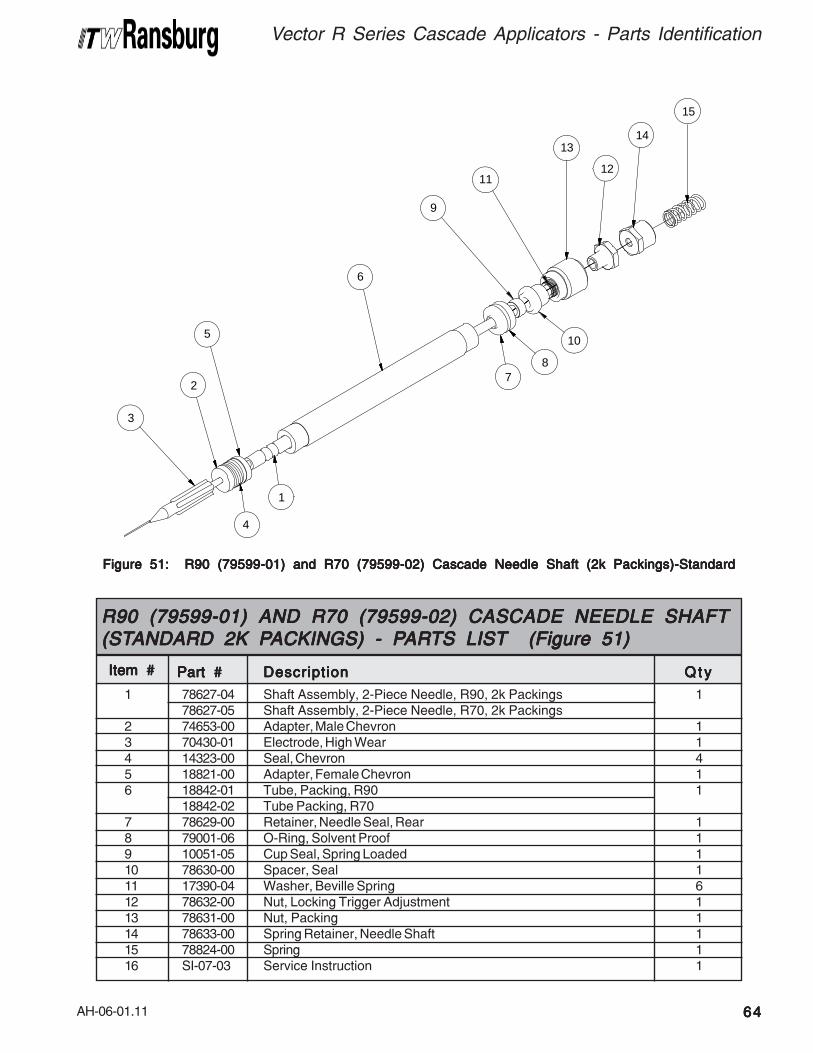
AH-06-01.11
Vector R Series Cascade Applicators - Parts Identification
6464646464
1 78627-04 Shaft Assembly, 2-Piece Needle, R90, 2k Packings 178627-05 Shaft Assembly, 2-Piece Needle, R70, 2k Packings
2 74653-00 Adapter, Male Chevron 13 70430-01 Electrode, High Wear 14 14323-00 Seal, Chevron 45 18821-00 Adapter, Female Chevron 16 18842-01 Tube, Packing, R90 1
18842-02 Tube Packing, R707 78629-00 Retainer, Needle Seal, Rear 18 79001-06 O-Ring, Solvent Proof 19 10051-05 Cup Seal, Spring Loaded 110 78630-00 Spacer, Seal 111 17390-04 Washer, Beville Spring 612 78632-00 Nut, Locking Trigger Adjustment 113 78631-00 Nut, Packing 114 78633-00 Spring Retainer, Needle Shaft 115 78824-00 Spring 116 SI-07-03 Service Instruction 1
Item #Item #Item #Item #Item #
R90 (79599-01) AND R70 (79599-02) CASCADE NEEDLE SHAFTR90 (79599-01) AND R70 (79599-02) CASCADE NEEDLE SHAFTR90 (79599-01) AND R70 (79599-02) CASCADE NEEDLE SHAFTR90 (79599-01) AND R70 (79599-02) CASCADE NEEDLE SHAFTR90 (79599-01) AND R70 (79599-02) CASCADE NEEDLE SHAFT(ST(ST(ST(ST(STANDARD 2K PANDARD 2K PANDARD 2K PANDARD 2K PANDARD 2K PACKINGS) - PACKINGS) - PACKINGS) - PACKINGS) - PACKINGS) - PARARARARARTS LISTTS LISTTS LISTTS LISTTS LIST (Figure 51) (Figure 51) (Figure 51) (Figure 51) (Figure 51)
Part #Part #Part #Part #Part # DescriptionDescriptionDescriptionDescriptionDescription Q t yQ t yQ t yQ t yQ t y
3
2
5
6
7
10
9
13
12
14
15
8
4
1
11
Figure 51: R90 (79599-01) and R70 (79599-02) Cascade Needle Shaft (2k Packings)-StandardFigure 51: R90 (79599-01) and R70 (79599-02) Cascade Needle Shaft (2k Packings)-StandardFigure 51: R90 (79599-01) and R70 (79599-02) Cascade Needle Shaft (2k Packings)-StandardFigure 51: R90 (79599-01) and R70 (79599-02) Cascade Needle Shaft (2k Packings)-StandardFigure 51: R90 (79599-01) and R70 (79599-02) Cascade Needle Shaft (2k Packings)-Standard
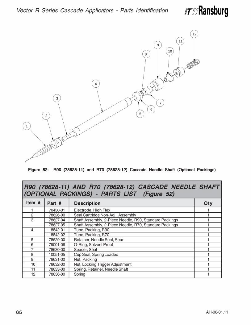
AH-06-01.11
Vector R Series Cascade Applicators - Parts Identification
6565656565
Figure 52: R90 (78628-11) and R70 (78628-12) Cascade Needle Shaft (Optional Packings)Figure 52: R90 (78628-11) and R70 (78628-12) Cascade Needle Shaft (Optional Packings)Figure 52: R90 (78628-11) and R70 (78628-12) Cascade Needle Shaft (Optional Packings)Figure 52: R90 (78628-11) and R70 (78628-12) Cascade Needle Shaft (Optional Packings)Figure 52: R90 (78628-11) and R70 (78628-12) Cascade Needle Shaft (Optional Packings)
1
2
3
4
5
7
8
9
10
11
12
6
1 70430-01 Electrode, High Flex 12 78626-00 Seal Cartridge Non-Adj., Assembly 13 78627-04 Shaft Assembly, 2-Piece Needle, R90, Standard Packings 1
78627-05 Shaft Assembly, 2-Piece Needle, R70, Standard Packings 14 18842-01 Tube, Packing, R90 1
18842-02 Tube, Packing, R70 15 78629-00 Retainer, Needle Seal, Rear 16 79001-06 O-Ring, Solvent Proof 17 78630-00 Spacer, Seal 18 10051-05 Cup Seal, Spring Loaded 19 78631-00 Nut, Packing 110 78632-00 Nut, Locking Trigger Adjustment 111 78633-00 Spring, Retainer, Needle Shaft 112 78636-00 Spring 1
Item #Item #Item #Item #Item #
R90 (78628-1R90 (78628-1R90 (78628-1R90 (78628-1R90 (78628-11) AND R70 (78628-12) CASCADE NEEDLE SHAFT1) AND R70 (78628-12) CASCADE NEEDLE SHAFT1) AND R70 (78628-12) CASCADE NEEDLE SHAFT1) AND R70 (78628-12) CASCADE NEEDLE SHAFT1) AND R70 (78628-12) CASCADE NEEDLE SHAFT(OPTIONAL(OPTIONAL(OPTIONAL(OPTIONAL(OPTIONAL P P P P PACKINGS) - PACKINGS) - PACKINGS) - PACKINGS) - PACKINGS) - PARARARARARTS LISTTS LISTTS LISTTS LISTTS LIST (Figure 52) (Figure 52) (Figure 52) (Figure 52) (Figure 52)
Part #Part #Part #Part #Part # DescriptionDescriptionDescriptionDescriptionDescription Q t yQ t yQ t yQ t yQ t y
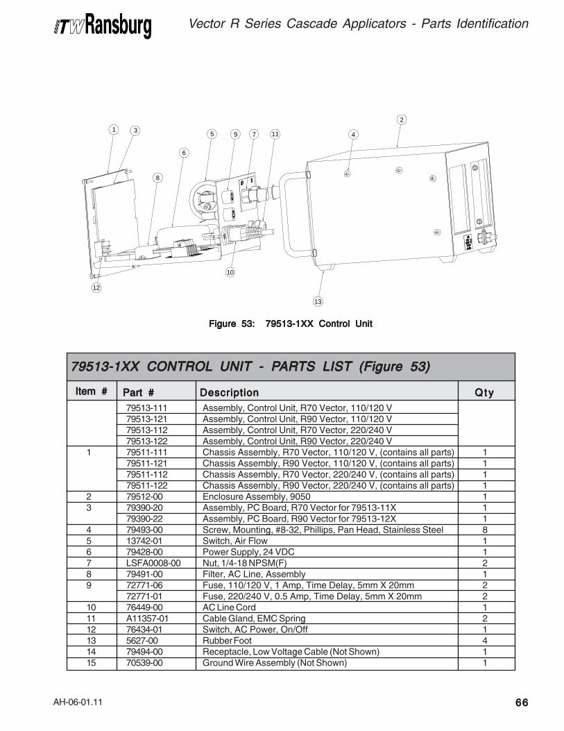
AH-06-01.11
Figure 53: 79513-1XX Control UnitFigure 53: 79513-1XX Control UnitFigure 53: 79513-1XX Control UnitFigure 53: 79513-1XX Control UnitFigure 53: 79513-1XX Control Unit
1 3
8
6
5 9 7
10
11 4
2
12
13
79513-111 Assembly, Control Unit, R70 Vector, 110/120 V79513-121 Assembly, Control Unit, R90 Vector, 110/120 V79513-112 Assembly, Control Unit, R70 Vector, 220/240 V79513-122 Assembly, Control Unit, R90 Vector, 220/240 V
1 79511-111 Chassis Assembly, R70 Vector, 110/120 V, (contains all parts) 179511-121 Chassis Assembly, R90 Vector, 110/120 V, (contains all parts) 179511-112 Chassis Assembly, R70 Vector, 220/240 V, (contains all parts) 179511-122 Chassis Assembly, R90 Vector, 220/240 V, (contains all parts) 1
2 79512-00 Enclosure Assembly, 9050 13 79390-20 Assembly, PC Board, R70 Vector for 79513-11X 1
79390-22 Assembly, PC Board, R90 Vector for 79513-12X 14 79493-00 Screw, Mounting, #8-32, Phillips, Pan Head, Stainless Steel 85 13742-01 Switch, Air Flow 16 79428-00 Power Supply, 24 VDC 17 LSFA0008-00 Nut, 1/4-18 NPSM(F) 28 79491-00 Filter, AC Line, Assembly 19 72771-06 Fuse, 110/120 V, 1 Amp, Time Delay, 5mm X 20mm 2
72771-01 Fuse, 220/240 V, 0.5 Amp, Time Delay, 5mm X 20mm 210 76449-00 AC Line Cord 111 A11357-01 Cable Gland, EMC Spring 212 76434-01 Switch, AC Power, On/Off 113 5627-00 Rubber Foot 414 79494-00 Receptacle, Low Voltage Cable (Not Shown) 115 70539-00 Ground Wire Assembly (Not Shown) 1
Item #Item #Item #Item #Item #
79513-1XX CONTROL79513-1XX CONTROL79513-1XX CONTROL79513-1XX CONTROL79513-1XX CONTROL UNIT UNIT UNIT UNIT UNIT - P - P - P - P - PARARARARARTS LISTTS LISTTS LISTTS LISTTS LIST (Figure 53) (Figure 53) (Figure 53) (Figure 53) (Figure 53)
Part #Part #Part #Part #Part # DescriptionDescriptionDescriptionDescriptionDescription Q t yQ t yQ t yQ t yQ t y
Vector R Series Cascade Applicators - Parts Identification
6666666666

AH-06-01.11
Vector R Series Cascade Applicators - Parts Identification
6767676767
NOTESNOTESNOTESNOTESNOTES
AH-06-01.11
WWWWWAAAAATERBORNE APPLICATERBORNE APPLICATERBORNE APPLICATERBORNE APPLICATERBORNE APPLICATTTTTOROROROROR
MODEL 79523-XXXXX SECTIONMODEL 79523-XXXXX SECTIONMODEL 79523-XXXXX SECTIONMODEL 79523-XXXXX SECTIONMODEL 79523-XXXXX SECTION
>Typical installations to spraynon-flammable conductive materials(waterborne materials) must not beused to handle flammable materials(solvent based materials).
W A R N I N GW A R N I N GW A R N I N GW A R N I N GW A R N I N G!!!!!
Vector R Series Cascade Applicators - Waterborne
6868686868
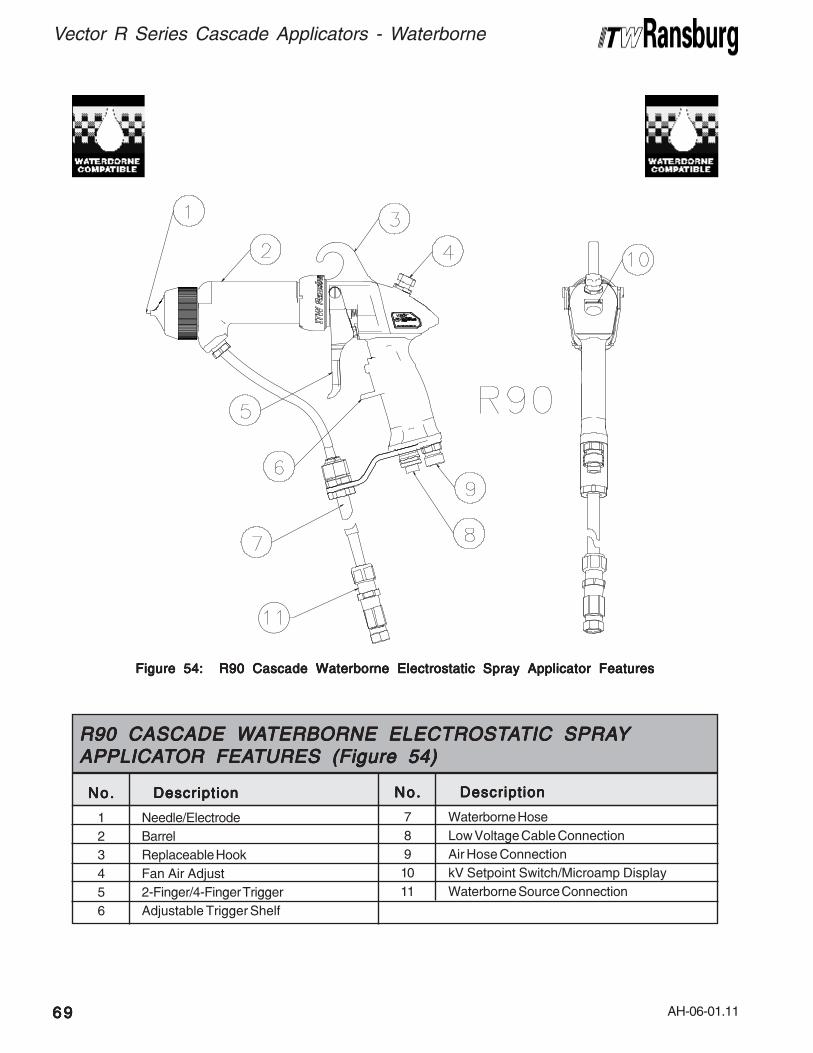
AH-06-01.11
Vector R Series Cascade Applicators - Waterborne
6969696969
1
2
3
4
5
6
No.No.No.No.No. DescriptionDescriptionDescriptionDescriptionDescription
Needle/Electrode
Barrel
Replaceable Hook
Fan Air Adjust
2-Finger/4-Finger Trigger
Adjustable Trigger Shelf
R90 CASCADE WR90 CASCADE WR90 CASCADE WR90 CASCADE WR90 CASCADE WAAAAATERBORNE ELECTROSTTERBORNE ELECTROSTTERBORNE ELECTROSTTERBORNE ELECTROSTTERBORNE ELECTROSTAAAAATIC SPRATIC SPRATIC SPRATIC SPRATIC SPRAYYYYYAPPLICAAPPLICAAPPLICAAPPLICAAPPLICATTTTTOR FEAOR FEAOR FEAOR FEAOR FEATURES (Figure 54)TURES (Figure 54)TURES (Figure 54)TURES (Figure 54)TURES (Figure 54)
7
8
9
10
11
No.No.No.No.No. DescriptionDescriptionDescriptionDescriptionDescription
Waterborne Hose
Low Voltage Cable Connection
Air Hose Connection
kV Setpoint Switch/Microamp Display
Waterborne Source Connection
Figure 54: R90 Cascade Waterborne Electrostatic Spray Applicator FeaturesFigure 54: R90 Cascade Waterborne Electrostatic Spray Applicator FeaturesFigure 54: R90 Cascade Waterborne Electrostatic Spray Applicator FeaturesFigure 54: R90 Cascade Waterborne Electrostatic Spray Applicator FeaturesFigure 54: R90 Cascade Waterborne Electrostatic Spray Applicator Features
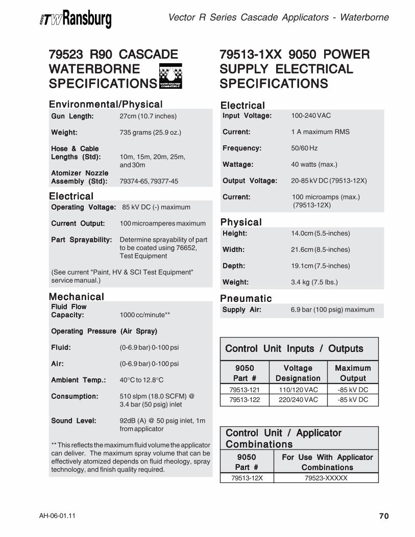
AH-06-01.11
Fluid FlowFluid FlowFluid FlowFluid FlowFluid Flow
Capacity:Capacity:Capacity:Capacity:Capacity: 1000 cc/minute**
Operating Pressure (Air Spray)Operating Pressure (Air Spray)Operating Pressure (Air Spray)Operating Pressure (Air Spray)Operating Pressure (Air Spray)
Fluid:Fluid:Fluid:Fluid:Fluid: (0-6.9 bar) 0-100 psi
Air :Air :Air :Air :Air : (0-6.9 bar) 0-100 psi
Ambient Temp.:Ambient Temp.:Ambient Temp.:Ambient Temp.:Ambient Temp.: 40°C to 12.8°C
Consumption:Consumption:Consumption:Consumption:Consumption: 510 slpm (18.0 SCFM) @3.4 bar (50 psig) inlet
Sound Level:Sound Level:Sound Level:Sound Level:Sound Level: 92dB (A) @ 50 psig inlet, 1mfrom applicator
** This reflects the maximum fluid volume the applicatorcan deliver. The maximum spray volume that can beeffectively atomized depends on fluid rheology, spraytechnology, and finish quality required.
Gun Length:Gun Length:Gun Length:Gun Length:Gun Length: 27cm (10.7 inches)
Weight:Weight:Weight:Weight:Weight: 735 grams (25.9 oz.)
Hose & CableHose & CableHose & CableHose & CableHose & Cable
Lengths (Std):Lengths (Std):Lengths (Std):Lengths (Std):Lengths (Std): 10m, 15m, 20m, 25m,and 30m
Atomizer NozzleAtomizer NozzleAtomizer NozzleAtomizer NozzleAtomizer Nozzle
Assembly (Std):Assembly (Std):Assembly (Std):Assembly (Std):Assembly (Std): 79374-65, 79377-45
Operating Voltage:Operating Voltage:Operating Voltage:Operating Voltage:Operating Voltage: 85 kV DC (-) maximum
Current Output:Current Output:Current Output:Current Output:Current Output: 100 microamperes maximum
Part Sprayability:Part Sprayability:Part Sprayability:Part Sprayability:Part Sprayability: Determine sprayability of partto be coated using 76652,Test Equipment
(See current "Paint, HV & SCI Test Equipment"service manual.)
79523 R90 CASCADE79523 R90 CASCADE79523 R90 CASCADE79523 R90 CASCADE79523 R90 CASCADE
WWWWWAAAAATERBORNETERBORNETERBORNETERBORNETERBORNE
SPECIFICASPECIFICASPECIFICASPECIFICASPECIFICATIONSTIONSTIONSTIONSTIONS
Environmental/PhysicalEnvironmental/PhysicalEnvironmental/PhysicalEnvironmental/PhysicalEnvironmental/Physical
ElectricalElectricalElectricalElectricalElectrical
MechanicalMechanicalMechanicalMechanicalMechanical
79513-1XX 9050 POWER79513-1XX 9050 POWER79513-1XX 9050 POWER79513-1XX 9050 POWER79513-1XX 9050 POWER
SUPPLSUPPLSUPPLSUPPLSUPPLYYYYY ELECTRICAL ELECTRICAL ELECTRICAL ELECTRICAL ELECTRICAL
SPECIFICASPECIFICASPECIFICASPECIFICASPECIFICATIONSTIONSTIONSTIONSTIONS
Input Voltage:Input Voltage:Input Voltage:Input Voltage:Input Voltage: 100-240 VAC
Current:Current:Current:Current:Current: 1 A maximum RMS
Frequency:Frequency:Frequency:Frequency:Frequency: 50/60 Hz
Wattage:Wattage:Wattage:Wattage:Wattage: 40 watts (max.)
Output Voltage:Output Voltage:Output Voltage:Output Voltage:Output Voltage: 20-85 kV DC (79513-12X)
Current:Current:Current:Current:Current: 100 microamps (max.) (79513-12X)
ElectricalElectricalElectricalElectricalElectrical
Height:Height:Height:Height:Height: 14.0cm (5.5-inches)
Width:Width:Width:Width:Width: 21.6cm (8.5-inches)
Depth:Depth:Depth:Depth:Depth: 19.1cm (7.5-inches)
Weight:Weight:Weight:Weight:Weight: 3.4 kg (7.5 lbs.)
PhysicalPhysicalPhysicalPhysicalPhysical
Supply Air:Supply Air:Supply Air:Supply Air:Supply Air: 6.9 bar (100 psig) maximum
PneumaticPneumaticPneumaticPneumaticPneumatic
110/120 VAC
220/240 VAC
79513-121
79513-122
-85 kV DC
-85 kV DC
VoltageVoltageVoltageVoltageVoltage
DesignationDesignationDesignationDesignationDesignation
MaximumMaximumMaximumMaximumMaximum
OutputOutputOutputOutputOutput
90509050905090509050
Part #Part #Part #Part #Part #
Control Unit Inputs / OutputsControl Unit Inputs / OutputsControl Unit Inputs / OutputsControl Unit Inputs / OutputsControl Unit Inputs / Outputs
79523-XXXXX79513-12X
For Use With ApplicatorFor Use With ApplicatorFor Use With ApplicatorFor Use With ApplicatorFor Use With Applicator
CombinationsCombinationsCombinationsCombinationsCombinations
90509050905090509050
Part #Part #Part #Part #Part #
Control Unit / ApplicatorControl Unit / ApplicatorControl Unit / ApplicatorControl Unit / ApplicatorControl Unit / Applicator
CombinationsCombinationsCombinationsCombinationsCombinations
Vector R Series Cascade Applicators - Waterborne
7070707070
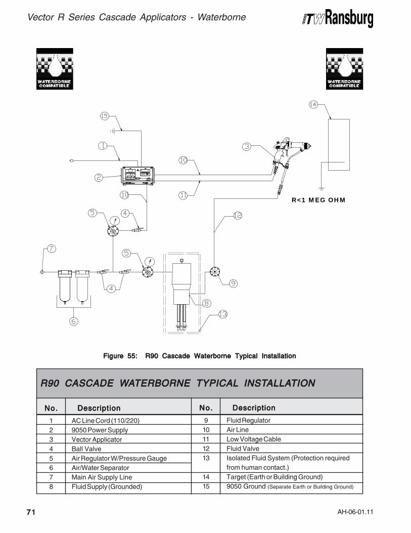
AH-06-01.11
Vector R Series Cascade Applicators - Waterborne
7171717171
Figure 55: R90 Cascade Waterborne Typical InstallationFigure 55: R90 Cascade Waterborne Typical InstallationFigure 55: R90 Cascade Waterborne Typical InstallationFigure 55: R90 Cascade Waterborne Typical InstallationFigure 55: R90 Cascade Waterborne Typical Installation
R<1 MEG OHM
1
2
3
4
5
6
7
8
No.No.No.No.No. DescriptionDescriptionDescriptionDescriptionDescription
AC Line Cord (110/220)
9050 Power Supply
Vector Applicator
Ball Valve
Air Regulator W/Pressure Gauge
Air/Water Separator
Main Air Supply Line
Fluid Supply (Grounded)
R90 CASCADE WR90 CASCADE WR90 CASCADE WR90 CASCADE WR90 CASCADE WAAAAATERBORNE TYPICALTERBORNE TYPICALTERBORNE TYPICALTERBORNE TYPICALTERBORNE TYPICAL INST INST INST INST INSTALLAALLAALLAALLAALLATIONTIONTIONTIONTION
9
10
11
12
13
14
15
No.No.No.No.No. DescriptionDescriptionDescriptionDescriptionDescription
Fluid Regulator
Air Line
Low Voltage Cable
Fluid Valve
Isolated Fluid System (Protection required
from human contact.)
Target (Earth or Building Ground)
9050 Ground (Separate Earth or Building Ground)
AH-06-01.11
WWWWWAAAAATERBORNETERBORNETERBORNETERBORNETERBORNE
ISOLAISOLAISOLAISOLAISOLATION SYSTEMTION SYSTEMTION SYSTEMTION SYSTEMTION SYSTEM
INSTINSTINSTINSTINSTALLAALLAALLAALLAALLATIONTIONTIONTIONTION
GUIDELINESGUIDELINESGUIDELINESGUIDELINESGUIDELINES
Using waterborne coating with electrostaticequipment requires that the fluid source be isolatedfrom ground. Precautions should be taken toensure operator safety and system efficiency.The following guidelines should be followed:
• The fluid lines and source MUST be isolatedfrom ground. An isolating Paint Stand orsimilar isolating (non-porous) material MUSTbe used.
>Never use wood products, wooden
boxes, pallets, or boards as an isolator.Wood contains moisture and is a poorinsulator. Electrical current passing throughthese materials can ignite them, causing ahazardous condition.
C A U T I O NC A U T I O NC A U T I O NC A U T I O NC A U T I O N!!!!!
• Isolation stands MUST be at least 18-inchesfrom grounded booth walls, chain link fences,or other grounded objects.
• Air hoses to the pressure pot or pump on theinsulating stand should be non-conductiveplastic. Many rubber hoses will have staticgrounding circuits or carbon content and areNOT suitable for this application.
WWWWWAAAAATERBORNE HOSETERBORNE HOSETERBORNE HOSETERBORNE HOSETERBORNE HOSE
FITTING INSTFITTING INSTFITTING INSTFITTING INSTFITTING INSTALLAALLAALLAALLAALLATIONTIONTIONTIONTION
For 79523 R90 Cascade - Waterborne: ITWRansburg supplies the waterborne fluid hosefactory pre-assembled to the applicator unit.Standard hose lengths are 10m, 15m, and 25m.To modify the hose length, use the followingprocedures. All adjustments must be made at thesupply end of the system.
1. Remove the male connector and swivel fittingfrom the end of the fluid hose by turning the nut ofthe male connector counter-clockwise while holdingits main body.
2. Remove the male connector nut from the fluidhose.
3. Determine the hose length that is needed andcut the hose off squarely.
• All charged (isolated) systems MUST be insidea fence or cage to prevent contact by per-sonnel. An interlock system MUST be providedthat interrupts high voltage flow to the applicatorif the gate is opened.
• Air regulators for pots or pumps should bemounted remotely outside the fence or cagearea to facilitate changes in pressure withoutshutting the system down.
• Grounding hooks at the cage MUST be usedto ground the system when personnel areworking close by.
• Fluid lines to the applicator MUST be protectedfrom scraping and abrasion on the floor orsharp metal edges that could lead to voltagepin holing and loss of kV on the chargedsystem.
• Cleanliness and maintenance are extremelycritical.
• Refer to "Installation - 79500 R90 Solventborne,79501 R70 Solventborne Installation" in the"Installation" section of this manual.
>Typical installations to spray non-
flammable conductive materials (water-borne materials) must not be used tohandle flammable materials (solventbased materials).
W A R N I N GW A R N I N GW A R N I N GW A R N I N GW A R N I N G!!!!!
Vector R Series Cascade Applicators - Waterborne
7272727272

AH-06-01.11
Vector R Series Cascade Applicators - Waterborne
7373737373
4. Carefully score the outer jacket linearly andthen radially approximately 18-inches back fromthe cut end. Split the outer jacket along the linearscore mark and peel it away from the inner sheath.Then remove the jacket completely by tearingalong the radial score mark.
5. Lightly score the inner sheath linearly and thenradially 1-inch from the outer jacket. Split the innersheath along the linear score mark and peel itaway from the core fluid hose. Then remove thesheath completely by tearing along the radialscore mark.
6. Roll the inner sheath back over itself until ittouches the outer jacket.
7. Cut approximately 1/4-inch of inner sheath off.
>Special care must be taken when re-
moving the sheathing from the fluid hose.Make sure all tools are very sharp and onlyscore the surface of the sheath. Insertingthe knife too deep can score the surface ofthe core material and lead to pin-holing andfailure of the hose.
W A R N I N GW A R N I N GW A R N I N GW A R N I N GW A R N I N G!!!!!NOTESNOTESNOTESNOTESNOTES
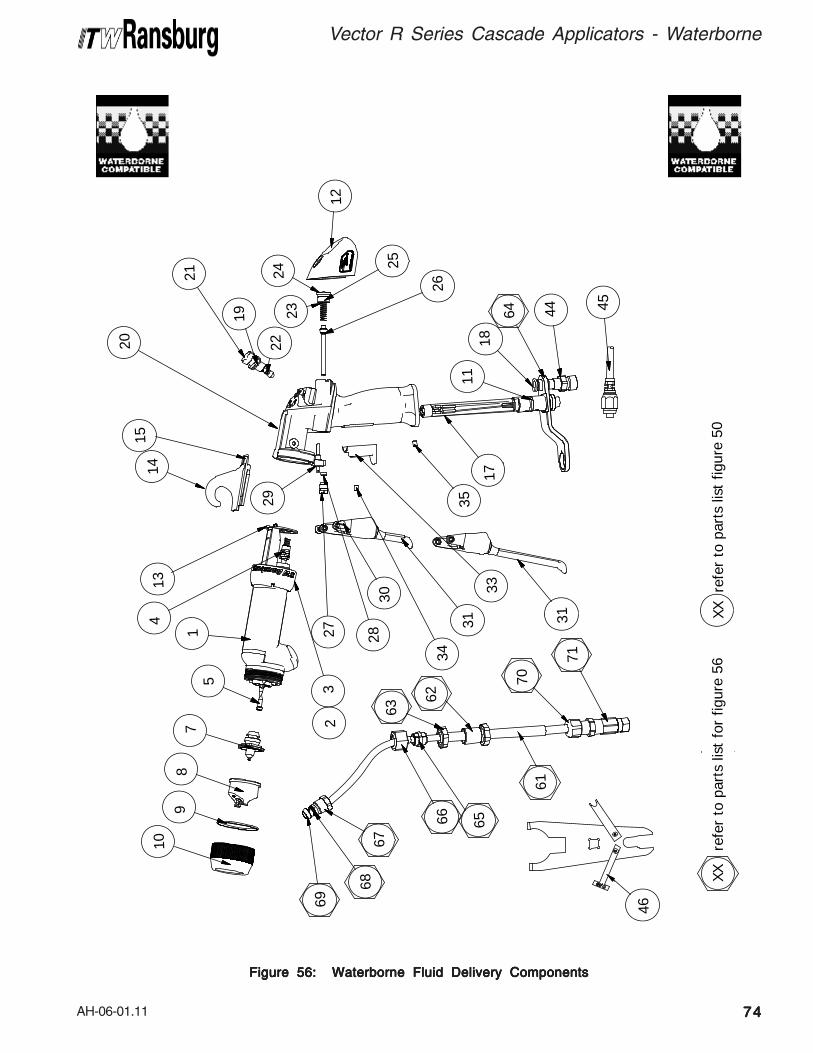
AH-06-01.11
Figure 56: Waterborne Fluid Delivery ComponentsFigure 56: Waterborne Fluid Delivery ComponentsFigure 56: Waterborne Fluid Delivery ComponentsFigure 56: Waterborne Fluid Delivery ComponentsFigure 56: Waterborne Fluid Delivery Components
45
66
63
62
65
71
70
XX
ref
er t
o pa
rts
list
for
figur
e 56
XX re
fer
to p
arts
list
fig
ure
50
61
46
4464
18
25
2324
12
26
1514
21
19
22
1711
32
29
13
35
4
15
78
910
68
69
67
20
2827
33
34
30
31 31
Vector R Series Cascade Applicators - Waterborne
7474747474
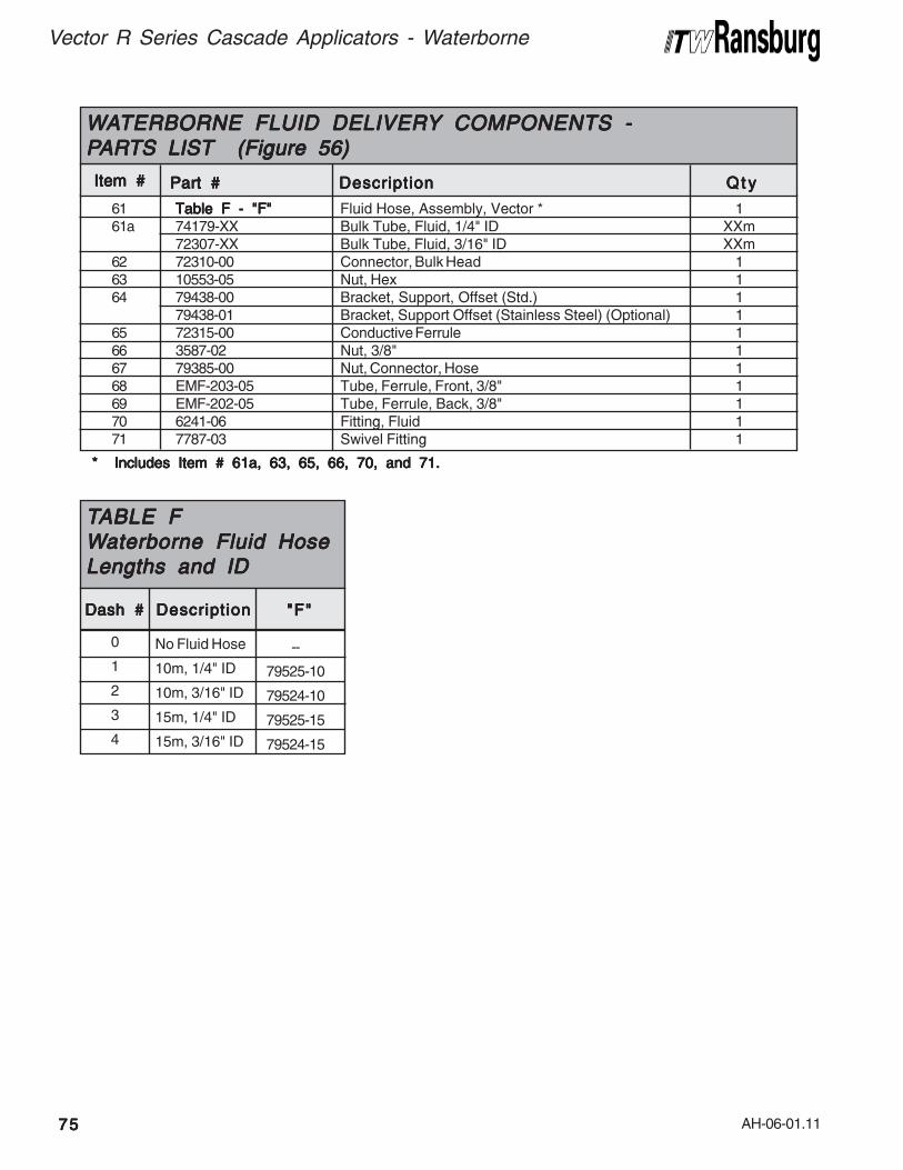
AH-06-01.11
Vector R Series Cascade Applicators - Waterborne
7575757575
* Includes Item # 61a, 63, 65, 66, 70, and 71.* Includes Item # 61a, 63, 65, 66, 70, and 71.* Includes Item # 61a, 63, 65, 66, 70, and 71.* Includes Item # 61a, 63, 65, 66, 70, and 71.* Includes Item # 61a, 63, 65, 66, 70, and 71.
61 Table F - "F"Table F - "F"Table F - "F"Table F - "F"Table F - "F" Fluid Hose, Assembly, Vector * 161a 74179-XX Bulk Tube, Fluid, 1/4" ID XXm
72307-XX Bulk Tube, Fluid, 3/16" ID XXm62 72310-00 Connector, Bulk Head 163 10553-05 Nut, Hex 164 79438-00 Bracket, Support, Offset (Std.) 1
79438-01 Bracket, Support Offset (Stainless Steel) (Optional) 165 72315-00 Conductive Ferrule 166 3587-02 Nut, 3/8" 167 79385-00 Nut, Connector, Hose 168 EMF-203-05 Tube, Ferrule, Front, 3/8" 169 EMF-202-05 Tube, Ferrule, Back, 3/8" 170 6241-06 Fitting, Fluid 171 7787-03 Swivel Fitting 1
Item #Item #Item #Item #Item #
WWWWWAAAAATERBORNE FLUID DELIVERTERBORNE FLUID DELIVERTERBORNE FLUID DELIVERTERBORNE FLUID DELIVERTERBORNE FLUID DELIVERYYYYY COMPONENTS - COMPONENTS - COMPONENTS - COMPONENTS - COMPONENTS -PPPPPARARARARARTS LISTTS LISTTS LISTTS LISTTS LIST (Figure 56) (Figure 56) (Figure 56) (Figure 56) (Figure 56)
Part #Part #Part #Part #Part # DescriptionDescriptionDescriptionDescriptionDescription Q t yQ t yQ t yQ t yQ t y
No Fluid Hose
10m, 1/4" ID
10m, 3/16" ID
15m, 1/4" ID
15m, 3/16" ID
--
79525-10
79524-10
79525-15
79524-15
"F""F""F""F""F"DescriptionDescriptionDescriptionDescriptionDescriptionDash #Dash #Dash #Dash #Dash #
0
1
2
3
4
TTTTTABLE FABLE FABLE FABLE FABLE FWWWWWaterborne Fluid Hoseaterborne Fluid Hoseaterborne Fluid Hoseaterborne Fluid Hoseaterborne Fluid HoseLengths and IDLengths and IDLengths and IDLengths and IDLengths and ID
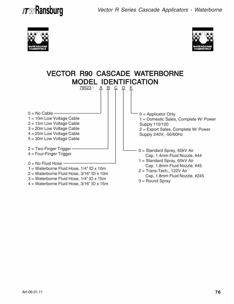
AH-06-01.11
Vector R Series Cascade Applicators - Waterborne
7676767676
0 = No Fluid Hose1 = Waterborne Fluid Hose, 1/4" ID x 10m2 = Waterborne Fluid Hose, 3/16" ID x 10m3 = Waterborne Fluid Hose, 1/4" ID x 15m4 = Waterborne Fluid Hose, 3/16" ID x 15m
79523 - A B C D E
0 = No Cable1 = 10m Low Voltage Cable2 = 15m Low Voltage Cable3 = 20m Low Voltage Cable4 = 25m Low Voltage Cable5 = 30m Low Voltage Cable
2 = Two-Finger Trigger4 = Four-Finger Trigger
0 = Standard Spray, 65kV AirCap, 1.4mm Fluid Nozzle, #44
1 = Standard Spray, 65kV AirCap, 1.8mm Fluid Nozzle, #45
2 = Trans-Tech., 122V AirCap, 1.8mm Fluid Nozzle, #245
3 = Round Spray
0 = Applicator Only1 = Domestic Sales, Complete W/ PowerSupply 110/1202 = Export Sales, Complete W/ PowerSupply 240V, -50/60Hz
VECTVECTVECTVECTVECTOR R90 CASCADE WOR R90 CASCADE WOR R90 CASCADE WOR R90 CASCADE WOR R90 CASCADE WAAAAATERBORNETERBORNETERBORNETERBORNETERBORNE
MODELMODELMODELMODELMODEL IDENTIFICA IDENTIFICA IDENTIFICA IDENTIFICA IDENTIFICATIONTIONTIONTIONTION

AH-06-01.11
Vector R Series Cascade Applicators - Parts Identification
7777777777
79547-10 Air Hose Assembly, 10m (33')79547-15 Air Hose Assembly, 15m (49')79547-20 Air Hose Assembly, 20m (66')79547-31 Air Hose Assembly, 30m (99')
1 LSFI0027 Reusable Hose Fitting 12 6919-XX Bulk Hose, Air XX
Item #Item #Item #Item #Item #
VECTVECTVECTVECTVECTOR AIR HOSE OPTIONS - POR AIR HOSE OPTIONS - POR AIR HOSE OPTIONS - POR AIR HOSE OPTIONS - POR AIR HOSE OPTIONS - PARARARARARTS LISTTS LISTTS LISTTS LISTTS LIST (Figure 62) (Figure 62) (Figure 62) (Figure 62) (Figure 62)
Part #Part #Part #Part #Part # DescriptionDescriptionDescriptionDescriptionDescription Q t yQ t yQ t yQ t yQ t y
2 1
Figure 62: Optional Air HoseFigure 62: Optional Air HoseFigure 62: Optional Air HoseFigure 62: Optional Air HoseFigure 62: Optional Air Hose
1
2
3
4
Figure 63: Optional Fluid HoseFigure 63: Optional Fluid HoseFigure 63: Optional Fluid HoseFigure 63: Optional Fluid HoseFigure 63: Optional Fluid Hose
79548-10 Fluid Hose Assembly, 10m (33')79548-15 Fluid Hose Assembly, 15m (49')79548-20 Fluid Hose Assembly, 20m (66')79548-31 Fluid Hose Assembly, 30m (99')
1 14599-00 Nut 12 7623-00 Union Stem 13 7617-00 Ferrule 14 77031-XX Bulk Hose, Fluid XX
Item #Item #Item #Item #Item #
VECTVECTVECTVECTVECTOR FLUID HOSE OPTIONS - POR FLUID HOSE OPTIONS - POR FLUID HOSE OPTIONS - POR FLUID HOSE OPTIONS - POR FLUID HOSE OPTIONS - PARARARARARTS LISTTS LISTTS LISTTS LISTTS LIST (Figure 63) (Figure 63) (Figure 63) (Figure 63) (Figure 63)
Part #Part #Part #Part #Part # DescriptionDescriptionDescriptionDescriptionDescription Q t yQ t yQ t yQ t yQ t y
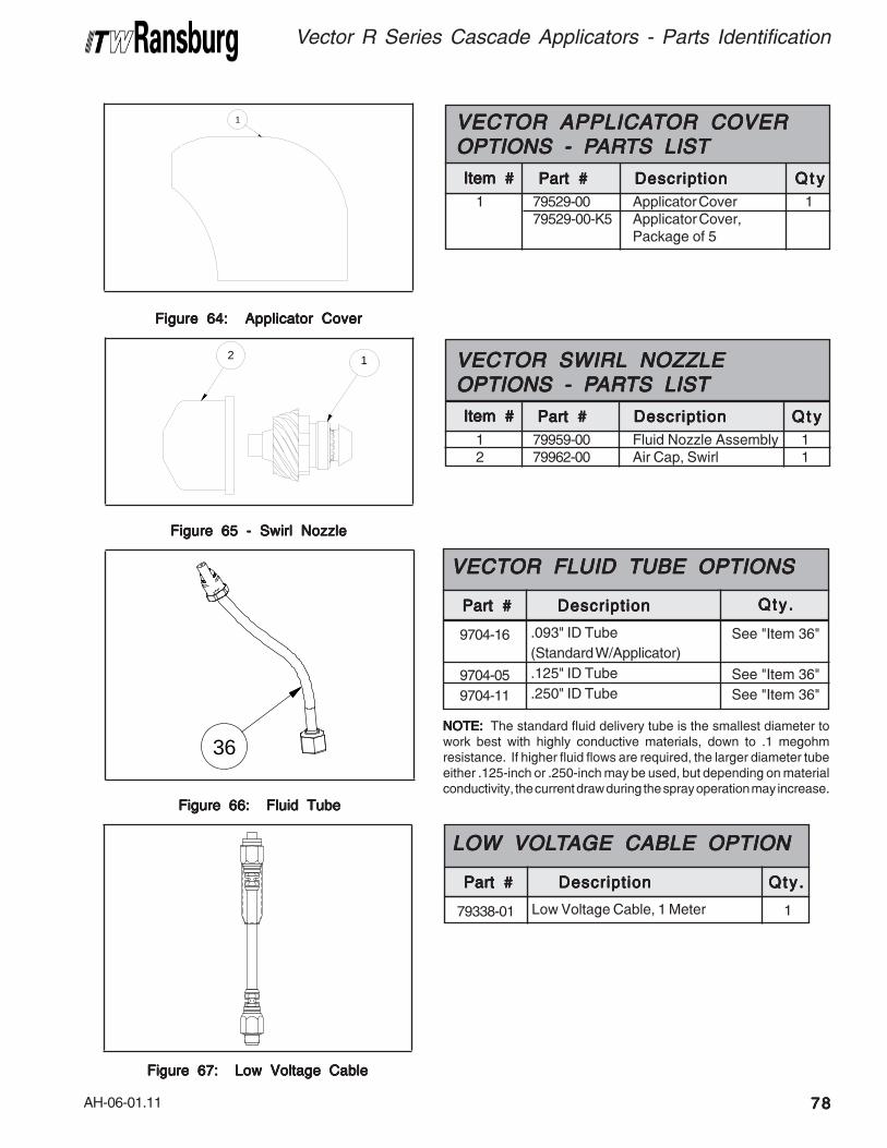
AH-06-01.11
1 79529-00 Applicator Cover 179529-00-K5 Applicator Cover,
Package of 5
Item #Item #Item #Item #Item #
VECTVECTVECTVECTVECTOR APPLICAOR APPLICAOR APPLICAOR APPLICAOR APPLICATTTTTOR COVEROR COVEROR COVEROR COVEROR COVEROPTIONS - POPTIONS - POPTIONS - POPTIONS - POPTIONS - PARARARARARTS LISTTS LISTTS LISTTS LISTTS LIST
Part #Part #Part #Part #Part # DescriptionDescriptionDescriptionDescriptionDescription Q t yQ t yQ t yQ t yQ t y
Figure 64: Applicator CoverFigure 64: Applicator CoverFigure 64: Applicator CoverFigure 64: Applicator CoverFigure 64: Applicator Cover
1 79959-00 Fluid Nozzle Assembly 12 79962-00 Air Cap, Swirl 1
Item #Item #Item #Item #Item #
VECTOR SWIRL NOZZLEVECTOR SWIRL NOZZLEVECTOR SWIRL NOZZLEVECTOR SWIRL NOZZLEVECTOR SWIRL NOZZLEOPTIONS - POPTIONS - POPTIONS - POPTIONS - POPTIONS - PARARARARARTS LISTTS LISTTS LISTTS LISTTS LIST
Part #Part #Part #Part #Part # DescriptionDescriptionDescriptionDescriptionDescription Q t yQ t yQ t yQ t yQ t y
Figure 65 - Swirl NozzleFigure 65 - Swirl NozzleFigure 65 - Swirl NozzleFigure 65 - Swirl NozzleFigure 65 - Swirl Nozzle
Figure 66: Fluid TubeFigure 66: Fluid TubeFigure 66: Fluid TubeFigure 66: Fluid TubeFigure 66: Fluid Tube
DescriptionDescriptionDescriptionDescriptionDescriptionPart #Part #Part #Part #Part #
79338-01
LOW VOLLOW VOLLOW VOLLOW VOLLOW VOLTTTTTAGE CABLE OPTIONAGE CABLE OPTIONAGE CABLE OPTIONAGE CABLE OPTIONAGE CABLE OPTION
Qty.Qty .Qty .Qty .Qty .
Low Voltage Cable, 1 Meter 1
Figure 67: Low Voltage CableFigure 67: Low Voltage CableFigure 67: Low Voltage CableFigure 67: Low Voltage CableFigure 67: Low Voltage Cable
1
36
DescriptionDescriptionDescriptionDescriptionDescriptionPart #Part #Part #Part #Part #
9704-16
9704-05
9704-11
VECTOR FLUID TUBE OPTIONSVECTOR FLUID TUBE OPTIONSVECTOR FLUID TUBE OPTIONSVECTOR FLUID TUBE OPTIONSVECTOR FLUID TUBE OPTIONS
Qty.Qty .Qty .Qty .Qty .
.093" ID Tube
(Standard W/Applicator)
.125" ID Tube
.250" ID Tube
See "Item 36"
See "Item 36"
See "Item 36"
NOTE:NOTE:NOTE:NOTE:NOTE: The standard fluid delivery tube is the smallest diameter towork best with highly conductive materials, down to .1 megohmresistance. If higher fluid flows are required, the larger diameter tubeeither .125-inch or .250-inch may be used, but depending on materialconductivity, the current draw during the spray operation may increase.
Vector R Series Cascade Applicators - Parts Identification
7878787878
2 1
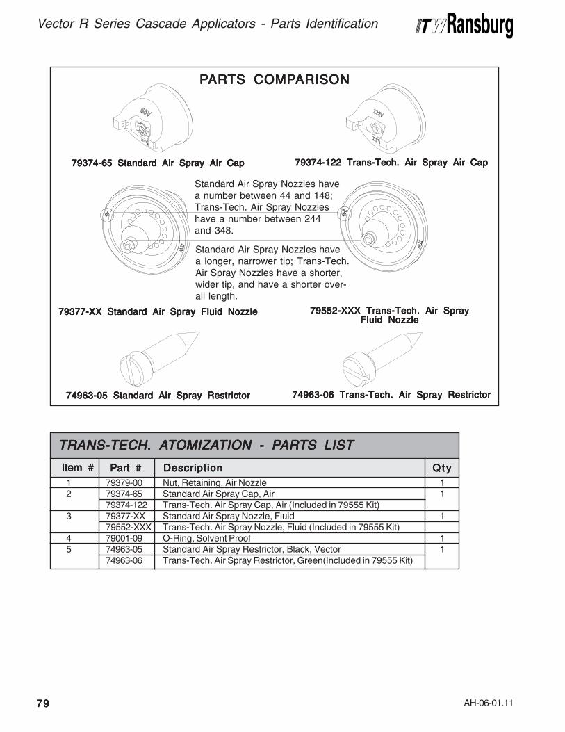
AH-06-01.11
Vector R Series Cascade Applicators - Parts Identification
7979797979
1 79379-00 Nut, Retaining, Air Nozzle 12 79374-65 Standard Air Spray Cap, Air 1
79374-122 Trans-Tech. Air Spray Cap, Air (Included in 79555 Kit)3 79377-XX Standard Air Spray Nozzle, Fluid 1
79552-XXX Trans-Tech. Air Spray Nozzle, Fluid (Included in 79555 Kit)4 79001-09 O-Ring, Solvent Proof 15 74963-05 Standard Air Spray Restrictor, Black, Vector 1
74963-06 Trans-Tech. Air Spray Restrictor, Green(Included in 79555 Kit)
Item #Item #Item #Item #Item #
TRANS-TECH. ATRANS-TECH. ATRANS-TECH. ATRANS-TECH. ATRANS-TECH. ATTTTTOMIZAOMIZAOMIZAOMIZAOMIZATION - PTION - PTION - PTION - PTION - PARARARARARTS LISTTS LISTTS LISTTS LISTTS LIST
Part #Part #Part #Part #Part # DescriptionDescriptionDescriptionDescriptionDescription Q t yQ t yQ t yQ t yQ t y
79374-65 Standard Air Spray Air Cap79374-65 Standard Air Spray Air Cap79374-65 Standard Air Spray Air Cap79374-65 Standard Air Spray Air Cap79374-65 Standard Air Spray Air Cap 79374-122 Trans-Tech. Air Spray Air Cap79374-122 Trans-Tech. Air Spray Air Cap79374-122 Trans-Tech. Air Spray Air Cap79374-122 Trans-Tech. Air Spray Air Cap79374-122 Trans-Tech. Air Spray Air Cap
79377-XX Standard Air Spray Fluid Nozzle79377-XX Standard Air Spray Fluid Nozzle79377-XX Standard Air Spray Fluid Nozzle79377-XX Standard Air Spray Fluid Nozzle79377-XX Standard Air Spray Fluid Nozzle 79552-XXX Trans-Tech. Air Spray79552-XXX Trans-Tech. Air Spray79552-XXX Trans-Tech. Air Spray79552-XXX Trans-Tech. Air Spray79552-XXX Trans-Tech. Air SprayFluid NozzleFluid NozzleFluid NozzleFluid NozzleFluid Nozzle
74963-05 Standard Air Spray Restrictor74963-05 Standard Air Spray Restrictor74963-05 Standard Air Spray Restrictor74963-05 Standard Air Spray Restrictor74963-05 Standard Air Spray Restrictor 74963-06 Trans-Tech. Air Spray Restrictor74963-06 Trans-Tech. Air Spray Restrictor74963-06 Trans-Tech. Air Spray Restrictor74963-06 Trans-Tech. Air Spray Restrictor74963-06 Trans-Tech. Air Spray Restrictor
PPPPPARARARARARTS COMPTS COMPTS COMPTS COMPTS COMPARISONARISONARISONARISONARISON
Standard Air Spray Nozzles havea number between 44 and 148;Trans-Tech. Air Spray Nozzleshave a number between 244and 348.
Standard Air Spray Nozzles havea longer, narrower tip; Trans-Tech.Air Spray Nozzles have a shorter,wider tip, and have a shorter over-all length.
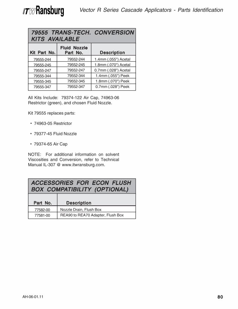
AH-06-01.11
Fluid NozzleFluid NozzleFluid NozzleFluid NozzleFluid NozzlePart No.Part No.Part No.Part No.Part No.Kit Part No.Kit Part No.Kit Part No.Kit Part No.Kit Part No.
79555-244
79555-245
79555-247
79555-344
79555-345
79555-347
79555 TRANS-TECH. CONVERSION79555 TRANS-TECH. CONVERSION79555 TRANS-TECH. CONVERSION79555 TRANS-TECH. CONVERSION79555 TRANS-TECH. CONVERSIONKITS AKITS AKITS AKITS AKITS AVVVVVAILABLEAILABLEAILABLEAILABLEAILABLE
DescriptionDescriptionDescriptionDescriptionDescription
79552-244
79552-245
79552-247
79552-344
79552-345
79552-347
1.4mm (.055") Acetal
1.8mm (.070") Acetal
0.7mm (.028") Acetal
1.4mm (.055") Peek
1.8mm (.070") Peek
0.7mm (.028") Peek
All Kits Include: 79374-122 Air Cap, 74963-06Restrictor (green), and chosen Fluid Nozzle.
Kit 79555 replaces parts:
• 74963-05 Restrictor
• 79377-45 Fluid Nozzle
• 79374-65 Air Cap
NOTE: For additional information on solventViscosities and Conversion, refer to TechnicalManual IL-307 @ www.itwransburg.com.
Part No.Part No.Part No.Part No.Part No.
77582-00
77581-00
ACCESSORIES FOR ECON FLUSHACCESSORIES FOR ECON FLUSHACCESSORIES FOR ECON FLUSHACCESSORIES FOR ECON FLUSHACCESSORIES FOR ECON FLUSHBOX COMPBOX COMPBOX COMPBOX COMPBOX COMPAAAAATIBILITYTIBILITYTIBILITYTIBILITYTIBILITY (OPTIONAL) (OPTIONAL) (OPTIONAL) (OPTIONAL) (OPTIONAL)
DescriptionDescriptionDescriptionDescriptionDescription
Nozzle Drain, Flush Box
REA90 to REA70 Adapter, Flush Box
Vector R Series Cascade Applicators - Parts Identification
8080808080

AH-06-01.11
Vector R Series Cascade Applicators - Parts Identification
8181818181
NOTESNOTESNOTESNOTESNOTES
79374-65
79374-65
79374-98
79374-98
79374-122
79374-122
Air CapAir CapAir CapAir CapAir CapPart #Part #Part #Part #Part # Orifice IDOrifice IDOrifice IDOrifice IDOrifice ID
Fluid NozzleFluid NozzleFluid NozzleFluid NozzleFluid NozzlePart #Part #Part #Part #Part #
79377-44
79377-45
79377-44
79377-45
79552-44
79552-45
AIR CAP / FLUID NOZZLE SELECTION CHARTAIR CAP / FLUID NOZZLE SELECTION CHARTAIR CAP / FLUID NOZZLE SELECTION CHARTAIR CAP / FLUID NOZZLE SELECTION CHARTAIR CAP / FLUID NOZZLE SELECTION CHARTAir Spray / TAir Spray / TAir Spray / TAir Spray / TAir Spray / Trans-Trans-Trans-Trans-Trans-Tech. Sprayech. Sprayech. Sprayech. Sprayech. Spray
SeparateSeparateSeparateSeparateSeparateRetaining RingRetaining RingRetaining RingRetaining RingRetaining Ring
PressurePressurePressurePressurePressureReducerReducerReducerReducerReducer
1.4mm (.055)
1.8mm (.070)
1.4mm (.055)
1.8mm (.070)
1.4mm (.055)
1.8mm (.070)
79379-00
79379-00
79379-00
79379-00
79379-00
79379-00
74963-05
74963-05
74963-05
74963-05
74963-06
74963-06
Orifice IDOrifice IDOrifice IDOrifice IDOrifice IDFluid NozzleFluid NozzleFluid NozzleFluid NozzleFluid Nozzle
Part #Part #Part #Part #Part #
79377-44
79377-144
79377-45
79377-145
79377-46
79377-146
79377-47
79377-147
79377-48
79377-148
FLUID NOZZLE SELECTIONFLUID NOZZLE SELECTIONFLUID NOZZLE SELECTIONFLUID NOZZLE SELECTIONFLUID NOZZLE SELECTIONSTD SPRASTD SPRASTD SPRASTD SPRASTD SPRAYYYYY CHAR CHAR CHAR CHAR CHARTTTTT
Nozzle MaterialNozzle MaterialNozzle MaterialNozzle MaterialNozzle Material
1.4mm (.055 inch)
1.4mm (.055 inch)
1.8mm (.070 inch)
1.8mm (.070 inch)
1.0mm (.042 inch)
1.0mm (.042 inch)
.7mm (.028 inch)
.7mm (.028 inch)
1.2mm (.047 inch)
1.2mm (.047 inch)
Standard Wear
Extended Wear
Standard Wear
Extended Wear
Standard Wear
Extended Wear
Standard Wear
Extended Wear
Standard Wear
Extended Wear
Orifice IDOrifice IDOrifice IDOrifice IDOrifice IDFluid NozzleFluid NozzleFluid NozzleFluid NozzleFluid Nozzle
Part #Part #Part #Part #Part #
79552-244
79552-344
79552-245
79552-345
79552-246
79552-346
79552-247
79552-347
79552-248
79552-348
FLUID NOZZLE SELECTIONFLUID NOZZLE SELECTIONFLUID NOZZLE SELECTIONFLUID NOZZLE SELECTIONFLUID NOZZLE SELECTIONTRANS-TECH. CHARTTRANS-TECH. CHARTTRANS-TECH. CHARTTRANS-TECH. CHARTTRANS-TECH. CHART
Nozzle MaterialNozzle MaterialNozzle MaterialNozzle MaterialNozzle Material
1.4mm (.055 inch)
1.4mm (.055 inch)
1.8mm (.070 inch)
1.8mm (.070 inch)
1.0mm (.042 inch)
1.0mm (.042 inch)
.7mm (.028 inch)
.7mm (.028 inch)
1.2mm (.047 inch)
1.2mm (.047 inch)
Standard Wear
Extended Wear
Standard Wear
Extended Wear
Standard Wear
Extended Wear
Standard Wear
Extended Wear
Standard Wear
Extended Wear

AH-06-01.11
(Continued On Next Page) (Continued On Next Page) (Continued On Next Page) (Continued On Next Page) (Continued On Next Page)
10051-05 Cup Seal, Spring Loaded 217130-00 Spring, Return 219749-00 Applicator Wrench Accessory3587-02 Nut and Ferrule 23587-03 Nut and Ferrule 259972-00 Dielectric Grease Accessory70430-01 Electrode High Flex 475326-00 Barret Retaining Ring 378626-00 Seal Cartridge 478627-04 Shaft Assembly, 2-Piece Needle, R90 278627-05 Shaft Assembly, 2-Piece Needle, R70 278628-11 Needle Shaft Assembly R90, Standard Packing 178628-12 Needle Shaft Assembly R70, Standard Packing 179629-00 2k Fluid Seal Repair Kit 179001-06 O-Ring, Solvent Proof 279001-07 O-Ring, Solvent Proof 479001-08 O-Ring, Solvent Proof 479001-09 O-Ring, Solvent Proof 679001-16 O-Ring, Solvent Proof 679001-31 O-Ring, Solvent Proof 279310-00 Air Valve Assembly 279322-00 Applicator Hook 179325-02 Trigger, 2-Finger 179338-01 Low Voltage Cable, 1m Accessory79338-10 Low Voltage Cable, 10m 179338-15 Low Voltage Cable, 15m Accessory79373-00 Barrel Retaining Nut 179374-65 Air Cap, V65 379374-98 Air Cap, V98 179377-44 Fluid Nozzle, 1.4mm/.055" 379377-45 Fluid Nozzle, 1.8mm/.070" 379378-00 Gasket, Barrel 279379-00 Air Cap Retaining Ring 279385-00 Nut Connector Hose 279438-00 Hose/Cable Support Bracket 179445-10 Fan Air Adjustment Assembly 279450-00 Trigger Stop Assembly 179454-00 Trigger Retaining Screws 479460-03 Plug Assembly 179468-00 Barrel, R90 Cascade 179468-00 Barrel, R70 Cascade 179471-01 Rear Cover W/Switch 179001-45 Applicator Hook Seal 179529-00-K5 Applicator Covers Accessory79560-00 Trigger Stop Assembly 179599-01 Needle Shaft Assembly, R90, 2k Packings 179599-02 Needle Shaft Assembly, R70, 2k Packings 1
VECTVECTVECTVECTVECTOR CASCADE APPLICAOR CASCADE APPLICAOR CASCADE APPLICAOR CASCADE APPLICAOR CASCADE APPLICATTTTTORS RECOMMENDEDORS RECOMMENDEDORS RECOMMENDEDORS RECOMMENDEDORS RECOMMENDEDSPSPSPSPSPARE PARE PARE PARE PARE PARARARARARTSTSTSTSTS
Part #Part #Part #Part #Part # DescriptionDescriptionDescriptionDescriptionDescription Q t yQ t yQ t yQ t yQ t y
Vector R Series Cascade Applicators - Parts Identification
8282828282
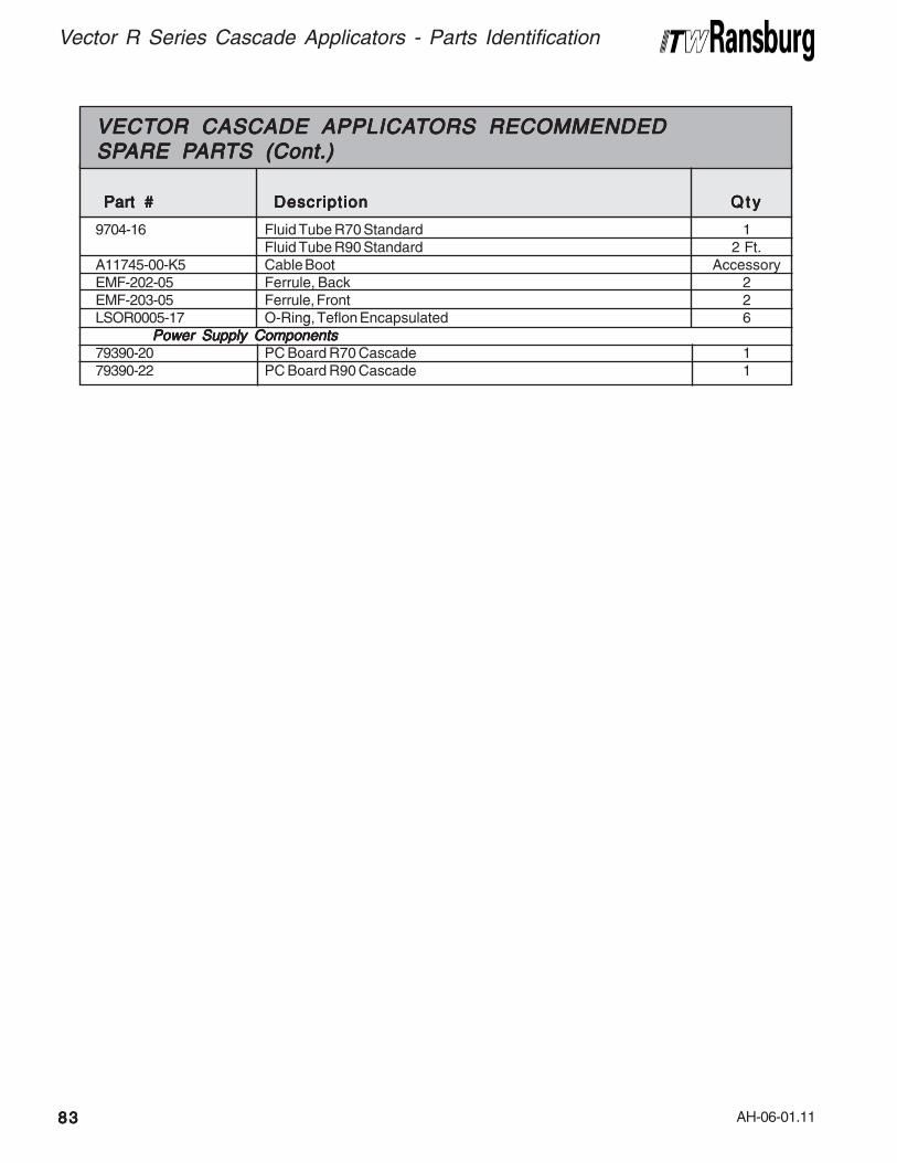
AH-06-01.11
Vector R Series Cascade Applicators - Parts Identification
8383838383
9704-16 Fluid Tube R70 Standard 1Fluid Tube R90 Standard 2 Ft.
A11745-00-K5 Cable Boot AccessoryEMF-202-05 Ferrule, Back 2EMF-203-05 Ferrule, Front 2LSOR0005-17 O-Ring, Teflon Encapsulated 6
Power Supply Components Power Supply Components Power Supply Components Power Supply Components Power Supply Components79390-20 PC Board R70 Cascade 179390-22 PC Board R90 Cascade 1
VECTVECTVECTVECTVECTOR CASCADE APPLICAOR CASCADE APPLICAOR CASCADE APPLICAOR CASCADE APPLICAOR CASCADE APPLICATTTTTORS RECOMMENDEDORS RECOMMENDEDORS RECOMMENDEDORS RECOMMENDEDORS RECOMMENDEDSPSPSPSPSPARE PARE PARE PARE PARE PARARARARARTS (Cont.)TS (Cont.)TS (Cont.)TS (Cont.)TS (Cont.)
Part #Part #Part #Part #Part # DescriptionDescriptionDescriptionDescriptionDescription Q t yQ t yQ t yQ t yQ t y
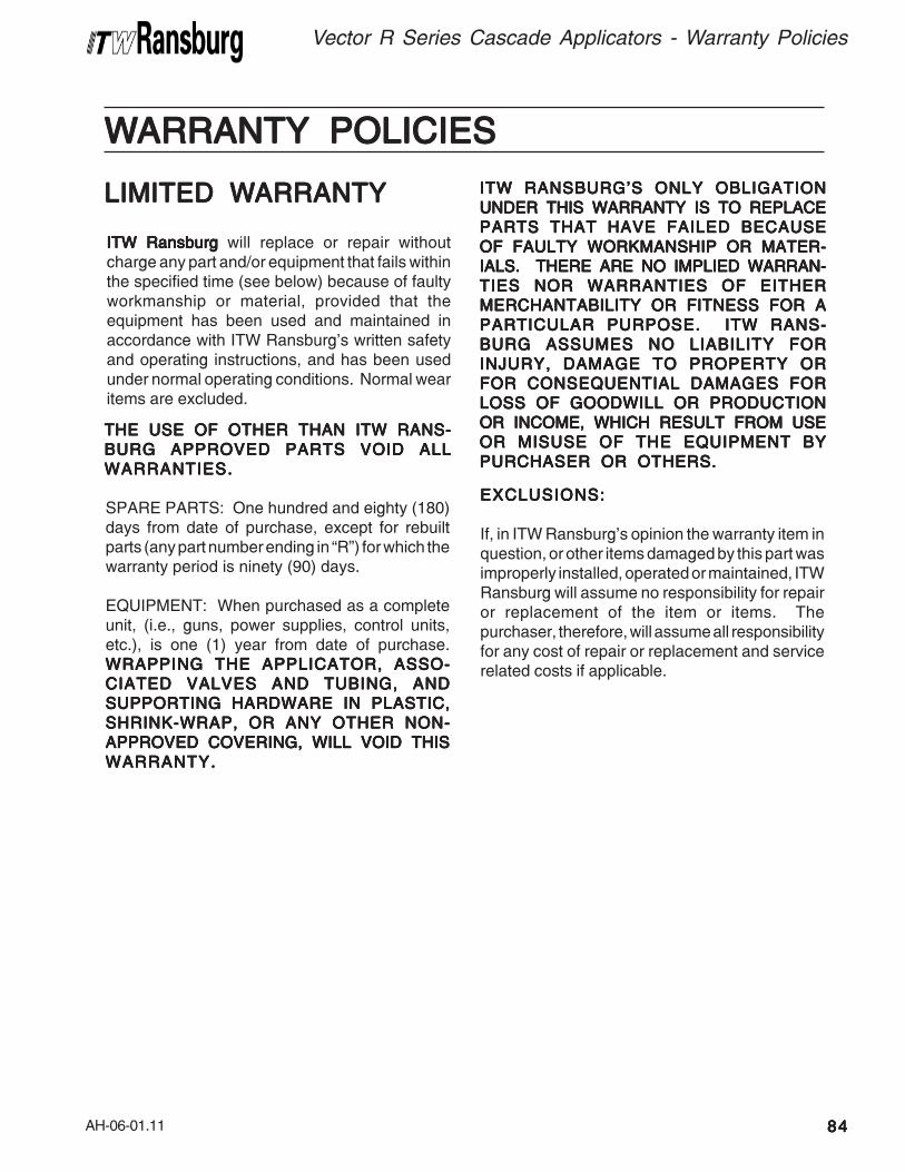
AH-06-01.11
WWWWWARRANTYARRANTYARRANTYARRANTYARRANTY POLICIES POLICIES POLICIES POLICIES POLICIES
LIMITED WLIMITED WLIMITED WLIMITED WLIMITED WARRANTYARRANTYARRANTYARRANTYARRANTY
ITW RansburgITW RansburgITW RansburgITW RansburgITW Ransburg will replace or repair withoutcharge any part and/or equipment that fails withinthe specified time (see below) because of faultyworkmanship or material, provided that theequipment has been used and maintained inaccordance with ITW Ransburg’s written safetyand operating instructions, and has been usedunder normal operating conditions. Normal wearitems are excluded.
THE USE OF OTHER THAN ITW RANS-THE USE OF OTHER THAN ITW RANS-THE USE OF OTHER THAN ITW RANS-THE USE OF OTHER THAN ITW RANS-THE USE OF OTHER THAN ITW RANS-
BURG APPROVED PARTS VOID ALLBURG APPROVED PARTS VOID ALLBURG APPROVED PARTS VOID ALLBURG APPROVED PARTS VOID ALLBURG APPROVED PARTS VOID ALL
WARRANTIES.WARRANTIES.WARRANTIES.WARRANTIES.WARRANTIES.
SPARE PARTS: One hundred and eighty (180)days from date of purchase, except for rebuiltparts (any part number ending in “R”) for which thewarranty period is ninety (90) days.
EQUIPMENT: When purchased as a completeunit, (i.e., guns, power supplies, control units,etc.), is one (1) year from date of purchase.
WRAPPING THE APPLICATOR, ASSO-WRAPPING THE APPLICATOR, ASSO-WRAPPING THE APPLICATOR, ASSO-WRAPPING THE APPLICATOR, ASSO-WRAPPING THE APPLICATOR, ASSO-
CIATED VALVES AND TUBING, ANDCIATED VALVES AND TUBING, ANDCIATED VALVES AND TUBING, ANDCIATED VALVES AND TUBING, ANDCIATED VALVES AND TUBING, AND
SUPPORTING HARDWARE IN PLASTIC,SUPPORTING HARDWARE IN PLASTIC,SUPPORTING HARDWARE IN PLASTIC,SUPPORTING HARDWARE IN PLASTIC,SUPPORTING HARDWARE IN PLASTIC,
SHRINK-WRAP, OR ANY OTHER NON-SHRINK-WRAP, OR ANY OTHER NON-SHRINK-WRAP, OR ANY OTHER NON-SHRINK-WRAP, OR ANY OTHER NON-SHRINK-WRAP, OR ANY OTHER NON-
APPROVED COVERING, WILL VOID THISAPPROVED COVERING, WILL VOID THISAPPROVED COVERING, WILL VOID THISAPPROVED COVERING, WILL VOID THISAPPROVED COVERING, WILL VOID THIS
WARRANTY.WARRANTY.WARRANTY.WARRANTY.WARRANTY.
ITW RANSBURG’S ONLY OBLIGATIONITW RANSBURG’S ONLY OBLIGATIONITW RANSBURG’S ONLY OBLIGATIONITW RANSBURG’S ONLY OBLIGATIONITW RANSBURG’S ONLY OBLIGATION
UNDER THIS WARRANTY IS TO REPLACEUNDER THIS WARRANTY IS TO REPLACEUNDER THIS WARRANTY IS TO REPLACEUNDER THIS WARRANTY IS TO REPLACEUNDER THIS WARRANTY IS TO REPLACE
PARTS THAT HAVE FAILED BECAUSEPARTS THAT HAVE FAILED BECAUSEPARTS THAT HAVE FAILED BECAUSEPARTS THAT HAVE FAILED BECAUSEPARTS THAT HAVE FAILED BECAUSE
OF FAULTY WORKMANSHIP OR MATER-OF FAULTY WORKMANSHIP OR MATER-OF FAULTY WORKMANSHIP OR MATER-OF FAULTY WORKMANSHIP OR MATER-OF FAULTY WORKMANSHIP OR MATER-
IALS. THERE ARE NO IMPLIED WARRAN-IALS. THERE ARE NO IMPLIED WARRAN-IALS. THERE ARE NO IMPLIED WARRAN-IALS. THERE ARE NO IMPLIED WARRAN-IALS. THERE ARE NO IMPLIED WARRAN-
TIES NOR WARRANTIES OF EITHERTIES NOR WARRANTIES OF EITHERTIES NOR WARRANTIES OF EITHERTIES NOR WARRANTIES OF EITHERTIES NOR WARRANTIES OF EITHER
MERCHANTABILITY OR FITNESS FOR AMERCHANTABILITY OR FITNESS FOR AMERCHANTABILITY OR FITNESS FOR AMERCHANTABILITY OR FITNESS FOR AMERCHANTABILITY OR FITNESS FOR A
PARTICULAR PURPOSE. ITW RANS-PARTICULAR PURPOSE. ITW RANS-PARTICULAR PURPOSE. ITW RANS-PARTICULAR PURPOSE. ITW RANS-PARTICULAR PURPOSE. ITW RANS-
BURG ASSUMES NO LIABILITY FORBURG ASSUMES NO LIABILITY FORBURG ASSUMES NO LIABILITY FORBURG ASSUMES NO LIABILITY FORBURG ASSUMES NO LIABILITY FOR
INJURY, DAMAGE TO PROPERTY ORINJURY, DAMAGE TO PROPERTY ORINJURY, DAMAGE TO PROPERTY ORINJURY, DAMAGE TO PROPERTY ORINJURY, DAMAGE TO PROPERTY OR
FOR CONSEQUENTIAL DAMAGES FORFOR CONSEQUENTIAL DAMAGES FORFOR CONSEQUENTIAL DAMAGES FORFOR CONSEQUENTIAL DAMAGES FORFOR CONSEQUENTIAL DAMAGES FOR
LOSS OF GOODWILL OR PRODUCTIONLOSS OF GOODWILL OR PRODUCTIONLOSS OF GOODWILL OR PRODUCTIONLOSS OF GOODWILL OR PRODUCTIONLOSS OF GOODWILL OR PRODUCTION
OR INCOME, WHICH RESULT FROM USEOR INCOME, WHICH RESULT FROM USEOR INCOME, WHICH RESULT FROM USEOR INCOME, WHICH RESULT FROM USEOR INCOME, WHICH RESULT FROM USE
OR MISUSE OF THE EQUIPMENT BYOR MISUSE OF THE EQUIPMENT BYOR MISUSE OF THE EQUIPMENT BYOR MISUSE OF THE EQUIPMENT BYOR MISUSE OF THE EQUIPMENT BY
PURCHASER OR OTHERS.PURCHASER OR OTHERS.PURCHASER OR OTHERS.PURCHASER OR OTHERS.PURCHASER OR OTHERS.
EXCLUSIONS:EXCLUSIONS:EXCLUSIONS:EXCLUSIONS:EXCLUSIONS:
If, in ITW Ransburg’s opinion the warranty item inquestion, or other items damaged by this part wasimproperly installed, operated or maintained, ITWRansburg will assume no responsibility for repairor replacement of the item or items. Thepurchaser, therefore, will assume all responsibilityfor any cost of repair or replacement and servicerelated costs if applicable.
Vector R Series Cascade Applicators - Warranty Policies
8484848484

AH-06-01.11
MANUALMANUALMANUALMANUALMANUAL CHANGE SUMMAR CHANGE SUMMAR CHANGE SUMMAR CHANGE SUMMAR CHANGE SUMMARYYYYYThis manual was published to replace ServiceManual AH-06-01.10 Vector R Series CascadeAH-06-01.10 Vector R Series CascadeAH-06-01.10 Vector R Series CascadeAH-06-01.10 Vector R Series CascadeAH-06-01.10 Vector R Series Cascade
ApplicatorsApplicatorsApplicatorsApplicatorsApplicators, to make the following changes:
1. Updated configuration drawing 79947.
2. Added air quality recommendation.
3. Removed blank hook option from figures andparts list.
4. Updated hook o-ring part number.
5. Updated restrictor for round spray.
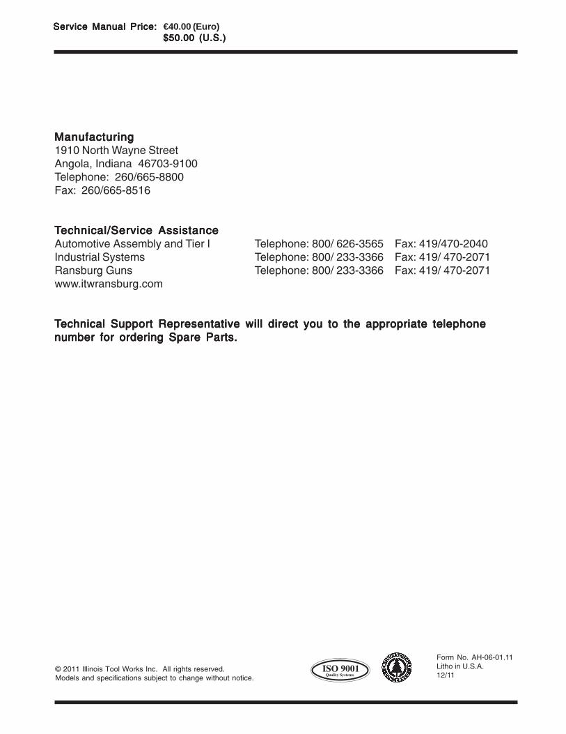
Form No. AH-06-01.11Litho in U.S.A.12/11
© 2011 Illinois Tool Works Inc. All rights reserved.Models and specifications subject to change without notice.
Service Manual Price:Service Manual Price:Service Manual Price:Service Manual Price:Service Manual Price: €40.00 (Euro)$50.00 (U.S.)$50.00 (U.S.)$50.00 (U.S.)$50.00 (U.S.)$50.00 (U.S.)
ManufacturingManufacturingManufacturingManufacturingManufacturing1910 North Wayne StreetAngola, Indiana 46703-9100Telephone: 260/665-8800Fax: 260/665-8516
TTTTTechnical/Service Assistanceechnical/Service Assistanceechnical/Service Assistanceechnical/Service Assistanceechnical/Service AssistanceAutomotive Assembly and Tier I Telephone: 800/ 626-3565 Fax: 419/470-2040Industrial Systems Telephone: 800/ 233-3366 Fax: 419/ 470-2071Ransburg Guns Telephone: 800/ 233-3366 Fax: 419/ 470-2071www.itwransburg.com
TTTTTechnical Support Representative will direct you to the appropriate telephoneechnical Support Representative will direct you to the appropriate telephoneechnical Support Representative will direct you to the appropriate telephoneechnical Support Representative will direct you to the appropriate telephoneechnical Support Representative will direct you to the appropriate telephone
number for ordering Spare Parts.number for ordering Spare Parts.number for ordering Spare Parts.number for ordering Spare Parts.number for ordering Spare Parts.