Embed Size (px)
Citation preview

AGS Proposal: Search for a permanent electric dipole
moment of the deuteron nucleus at the 10−29 e · cm level.
D. Anastassopoulos,21 V. Anastassopoulos,21 D. Babusci,8 M. Bai,4
G. Bennett,4 J. Bengtsson,4 I. Ben-Zvi,4 M. Blaskiewicz,4 K. Brown,4
G. Cantatore,17 M. Dabaghyan,20 V. Dzhordzhadze,4 P.D. Eversheim,2
M.E. Emirhan,11 G. Fanourakis,22 A. Facco,13 A. Fedotov,4 A. Ferrari,8
T. Geralis,22 Y. Giomataris,23 F. Gonnella,16 F. Gray,18 R. Gupta,4
S. Haciomeroglu,11 G. Hoffstaetter,6 H. Huang,4 M. Incagli,19 K. Jungmann,9
M. Karuza,17 D. Kawall,14 B. Khazin,5 I.B. Khriplovich,5 I.A. Koop,5
Y. Kuno,15 D.M. Lazarus,4 R. Larsen,4 P. Levi Sandri,8 F. Lin,4 A. Luccio,4
N. Malitsky,4 W.W. MacKay,4 W. Marciano,4 A. Masaharu,15 W. Meng,4
R. Messi,16 L. Miceli,4 J.P. Miller,3 D. Moricciani,16 W.M. Morse,4,a
C.J.G. Onderwater,9,b Y.F. Orlov,6,c C.S. Ozben,11 T. Papaevangelou,23
V. Ptitsyn,4 B. Parker,4 D. Raparia,4 S. Redin,5 S. Rescia,4 G. Ruoso,13
T. Russo,4 A. Sato,15 Y.K. Semertzidis,4,∗ Yu. Shatunov,5 V. Shemelin,6
A. Sidorin,12 A. Silenko,1 M. da Silva e Silva,9 N. Simos,4 E.J. Stephenson,10,d
G. Venanzoni,8 A. Vradis,21 G. Zavattini,7 A. Zelenski,4 K. Zioutas21
1Research Inst. for Nucl. Probl. of Belarusian State University, Minsk, Belarus;2University of Bonn, Bonn, D-53115, Germany; 3Boston University,
Boston, MA 02215; 4Brookhaven National Laboratory, Upton, NY 11973;5Budker Institute of Nuclear Physics, Novosibirsk, Russia; 6Cornell University,Ithaca, NY 14853; 7University and INFN, Ferrara, Italy; 8Laboratori Nazionalidi Frascati dell’INFN, Frascati, Italy; 9University of Groningen, NL-9747AA
Groningen, the Netherlands; 10Indiana University Cyclotron Facility,Bloomington, IN 47408; 11Istanbul Technical University, Istanbul 34469, Turkey;
12Joint Institute for Nuclear Research, Dubna, Moscow region, Russia;13Legnaro National Laboratories of INFN, Legnaro, Italy; 14University
of Massachusetts, Amherst, MA 01003; 15Osaka University, Osaka, Japan;16Dipartimento di Fisica, Universita’ “Tor Vergata” and Sezione INFN, Rome, Italy;
17University and INFN Trieste, Italy; 18Physics Dept., Regis University, Denver,CO 80221; 19University and INFN Pisa, Italy; 20Brigham and Women’s Hospital,
Harvard Medical School, Boston, MA 02115; 21University of Patras, Patras, Greece;22Institute of Nuclear Physics Dimokritos, Athens, Greece; 23Saclay/Paris, France
April, 2008
Requesting 4 × 10¹¹ vector polarized, bunched, 1 GeV/c total momentumdeuterons per 103 s cycle. Total running time 5000 hours.
∗ Interim Spokesperson, [email protected], +1(631)344-3881a Int. deputy Spokesperson for Systematic errors, [email protected], +1(631)344-3859b Int. deputy Spokesperson for DAQ & Electronics, [email protected], +31(50)363-3557c Int. deputy Spokesperson for beam & spin dynamics, [email protected], +1(607)255-3502d Int. deputy Spokesperson for polarimetry, [email protected], +1(812)855-5469.
1
Abstract
We propose using the storage ring method to measure the electric dipole moment (EDM)of D+, the bare deuteron nucleus, with a one sigma sensitivity of 10−29 e · cm per 107 srunning time. At this level it will be the best experiment among current and currentlyplanned EDM experiments. Its mass scale reach for SUSY-type new physics is more than300 TeV, or if there is physics at the LHC scale, its sensitivity to CP-violating phases is10−5 rad; both scales are much beyond the design sensitivity of the LHC.
High intensity, polarized deuteron sources, polarimeters with high analyzing powers at1 GeV/c total deuteron momentum, and the application of common accelerator techniquesmake this goal possible. The polarimeter systematic errors are minimized by applying sym-metries related to the deuteron spin direction and the EDM signal. In addition, the slowbeam extraction onto a solid carbon target aided by a precise beam position monitor-ing system ensures that the beam direction axis will remain the same within very tightlimits during the storage time. The widening of the polarimeter detector capabilities togive counting as well as directional information will severely restrict the larger polarimetersystematic errors to well below the 10−29 e·cm level. We are perfecting those techniques byrunning very important hardware tests at KVI (the Netherlands) and COSY (Germany),where polarized deuteron beams are currently available.
2
Contents
1 Introduction 21.1 The frozen spin concept . . . . . . . . . . . . . . . . . . . . . . . . . . . . . 31.2 What is different from the 2004 proposal . . . . . . . . . . . . . . . . . . . . 3
2 Motivation for the Deuteron Electric Dipole Moment Experiment 52.1 The QCD CP-violating parameter θ . . . . . . . . . . . . . . . . . . . . . . 62.2 Supersymmetry . . . . . . . . . . . . . . . . . . . . . . . . . . . . . . . . . . 72.3 Dimensional Analysis . . . . . . . . . . . . . . . . . . . . . . . . . . . . . . . 8
3 Concept of Experiment 83.1 Overview of the Experimental Technique . . . . . . . . . . . . . . . . . . . . 83.2 Polarimeter Design Considerations . . . . . . . . . . . . . . . . . . . . . . . 11
3.2.1 Polarimeter Design . . . . . . . . . . . . . . . . . . . . . . . . . . . . 123.2.2 Polarimeter errors . . . . . . . . . . . . . . . . . . . . . . . . . . . . 133.2.3 Running cycle . . . . . . . . . . . . . . . . . . . . . . . . . . . . . . . 143.2.4 Producing a Polarized Beam and What is Observed . . . . . . . . . 16
3.3 Statistical Accuracy . . . . . . . . . . . . . . . . . . . . . . . . . . . . . . . 18
4 Deuteron Storage Ring 194.1 Lattice Design Considerations . . . . . . . . . . . . . . . . . . . . . . . . . . 194.2 Polarization Lifetime (Spin Coherence Time) . . . . . . . . . . . . . . . . . 214.3 Non-Commutativity of Spin Rotations Imitating the EDM Rotation . . . . 234.4 Magnetic/Electric Field: Monitoring and Feedback Stabilization . . . . . . 23
5 Systematic Errors 245.1 Systematic Errors Due to Electric and Magnetic Field Imperfections . . . . 245.2 Polarimeter Systematic Errors . . . . . . . . . . . . . . . . . . . . . . . . . . 305.3 Pickup Electrodes . . . . . . . . . . . . . . . . . . . . . . . . . . . . . . . . 33
6 Cooled deuteron beam 34
7 DAQ and Electronics 35
8 Cost and Schedule 368.1 Storage Ring . . . . . . . . . . . . . . . . . . . . . . . . . . . . . . . . . . . 378.2 Experimental Systems . . . . . . . . . . . . . . . . . . . . . . . . . . . . . . 378.3 Total deuteron EDM ring cost . . . . . . . . . . . . . . . . . . . . . . . . . . 378.4 Beamline and Conventional Facilities . . . . . . . . . . . . . . . . . . . . . . 37
9 Conclusion 38
1
1 Introduction
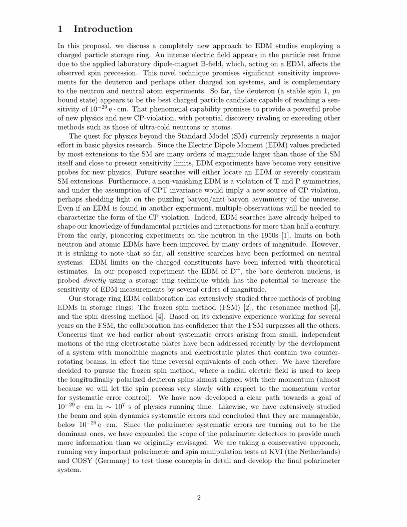
In this proposal, we discuss a completely new approach to EDM studies employing acharged particle storage ring. An intense electric field appears in the particle rest framedue to the applied laboratory dipole-magnet B-field, which, acting on a EDM, affects theobserved spin precession. This novel technique promises significant sensitivity improve-ments for the deuteron and perhaps other charged ion systems, and is complementaryto the neutron and neutral atom experiments. So far, the deuteron (a stable spin 1, pnbound state) appears to be the best charged particle candidate capable of reaching a sen-sitivity of 10−29 e · cm. That phenomenal capability promises to provide a powerful probeof new physics and new CP-violation, with potential discovery rivaling or exceeding othermethods such as those of ultra-cold neutrons or atoms.
The quest for physics beyond the Standard Model (SM) currently represents a majoreffort in basic physics research. Since the Electric Dipole Moment (EDM) values predictedby most extensions to the SM are many orders of magnitude larger than those of the SMitself and close to present sensitivity limits, EDM experiments have become very sensitiveprobes for new physics. Future searches will either locate an EDM or severely constrainSM extensions. Furthermore, a non-vanishing EDM is a violation of T and P symmetries,and under the assumption of CPT invariance would imply a new source of CP violation,perhaps shedding light on the puzzling baryon/anti-baryon asymmetry of the universe.Even if an EDM is found in another experiment, multiple observations will be needed tocharacterize the form of the CP violation. Indeed, EDM searches have already helped toshape our knowledge of fundamental particles and interactions for more than half a century.From the early, pioneering experiments on the neutron in the 1950s [1], limits on bothneutron and atomic EDMs have been improved by many orders of magnitude. However,it is striking to note that so far, all sensitive searches have been performed on neutralsystems. EDM limits on the charged constituents have been inferred with theoreticalestimates. In our proposed experiment the EDM of D+, the bare deuteron nucleus, isprobed directly using a storage ring technique which has the potential to increase thesensitivity of EDM measurements by several orders of magnitude.
Our storage ring EDM collaboration has extensively studied three methods of probingEDMs in storage rings: The frozen spin method (FSM) [2], the resonance method [3],and the spin dressing method [4]. Based on its extensive experience working for severalyears on the FSM, the collaboration has confidence that the FSM surpasses all the others.Concerns that we had earlier about systematic errors arising from small, independentmotions of the ring electrostatic plates have been addressed recently by the developmentof a system with monolithic magnets and electrostatic plates that contain two counter-rotating beams, in effect the time reversal equivalents of each other. We have thereforedecided to pursue the frozen spin method, where a radial electric field is used to keepthe longitudinally polarized deuteron spins almost aligned with their momentum (almostbecause we will let the spin precess very slowly with respect to the momentum vectorfor systematic error control). We have now developed a clear path towards a goal of10−29 e · cm in ∼ 107 s of physics running time. Likewise, we have extensively studiedthe beam and spin dynamics systematic errors and concluded that they are manageable,below 10−29 e · cm. Since the polarimeter systematic errors are turning out to be thedominant ones, we have expanded the scope of the polarimeter detectors to provide muchmore information than we originally envisaged. We are taking a conservative approach,running very important polarimeter and spin manipulation tests at KVI (the Netherlands)and COSY (Germany) to test these concepts in detail and develop the final polarimetersystem.
2
1.1 The frozen spin concept
We are proposing to store a longitudinally polarized deuteron beam of 1 GeV/c totalmomentum in a magnetic storage ring of 0.5 T. A particle in a magnetic storage ring witha vertical dipole magnetic field (B) will feel in its rest frame, in addition to the magneticfield, the presence of an electric field proportional to γ�v× �B, with v its velocity and γ itsLorentz factor. The direction of the electric field is radial inward, always orthogonal toboth the velocity and magnetic field vectors. If the particle has an EDM along its spindirection, this E-field will precess the particle spin into the vertical direction. This changeof the vertical component of the beam polarization from early to late storage times isthe signature of the EDM signal. The experiment is most sensitive when the deuteronspin is kept longitudinal, along the velocity vector, for the duration of the storage time.However, we will vary the horizontal precession rate in order to measure other polariationcomponents and constrain our systematic errors. We plan to control the horizontal spinprecession by using a radial E-field in the lab frame, produced by a pair of vertical capacitorplates. Without the radial E-field, the deuteron spin precesses slower than its momentumsince the deuteron anomalous magnetic moment is negative (ad = −0.142). This radialE-field is directed outwards, making the beam path longer for the same magnetic field andgiving the deuteron spin a chance to catch up to its momentum. With the estimated spincoherence time of 103 s the spin precession due to an EDM of 10−29 e · cm will produce achange in the vertical spin component of approximately 10μrad during the storage time.
1.2 What is different from the 2004 proposal
The new concepts that make the goal of the present proposal two orders of magnitudebetter than our September 2004 proposal are:
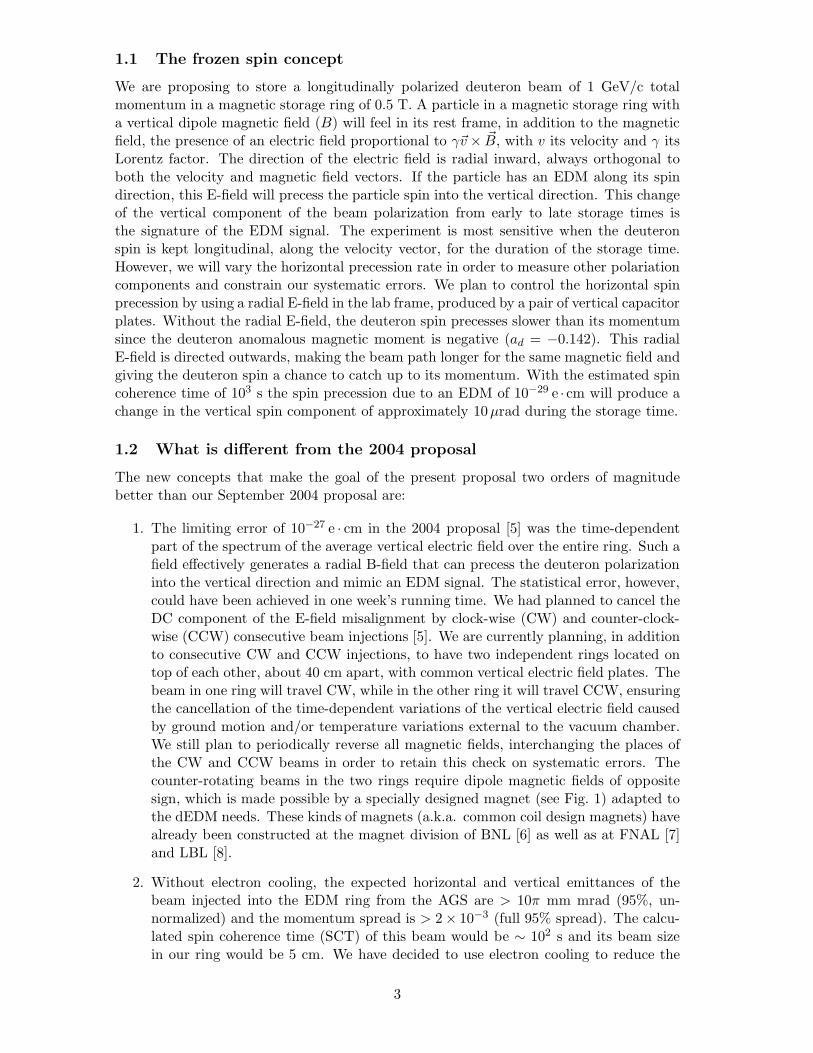
1. The limiting error of 10−27 e · cm in the 2004 proposal [5] was the time-dependentpart of the spectrum of the average vertical electric field over the entire ring. Such afield effectively generates a radial B-field that can precess the deuteron polarizationinto the vertical direction and mimic an EDM signal. The statistical error, however,could have been achieved in one week’s running time. We had planned to cancel theDC component of the E-field misalignment by clock-wise (CW) and counter-clock-wise (CCW) consecutive beam injections [5]. We are currently planning, in additionto consecutive CW and CCW injections, to have two independent rings located ontop of each other, about 40 cm apart, with common vertical electric field plates. Thebeam in one ring will travel CW, while in the other ring it will travel CCW, ensuringthe cancellation of the time-dependent variations of the vertical electric field causedby ground motion and/or temperature variations external to the vacuum chamber.We still plan to periodically reverse all magnetic fields, interchanging the places ofthe CW and CCW beams in order to retain this check on systematic errors. Thecounter-rotating beams in the two rings require dipole magnetic fields of oppositesign, which is made possible by a specially designed magnet (see Fig. 1) adapted tothe dEDM needs. These kinds of magnets (a.k.a. common coil design magnets) havealready been constructed at the magnet division of BNL [6] as well as at FNAL [7]and LBL [8].
2. Without electron cooling, the expected horizontal and vertical emittances of thebeam injected into the EDM ring from the AGS are > 10π mm mrad (95%, un-normalized) and the momentum spread is > 2× 10⁻³ (full 95% spread). The calcu-lated spin coherence time (SCT) of this beam would be ∼ 102 s and its beam sizein our ring would be 5 cm. We have decided to use electron cooling to reduce the
3
Figure 1: A schematic of the common coil magnet design (the horizontal and verticalscales are not the same). When the deuteron beam travels CW in aperture 1, the beamtravels CCW in aperture 2.
horizontal emittance to 3π mm mrad (95%, absolute) and the momentum spreadto 10−3 (full spread 95%). The SCT is then estimated to be better than ∼ 103 s,while the horizontal beam size is going to be smaller than ±1 cm. The experimentalstatistical error due to the expected increase in SCT (τ) goes as 1/
√τ .
3. The statistical significance of the experiment scales roughly as the particle velocitytimes the dipole magnetic field strength, both of which depend on the strength of theradial electric field that can be safely applied in the ring to freeze the deuteron spindirection. Recent breakthroughs in the preparation of normal conducting surfaceshave made possible the achievement of much higher electric fields [9]. Including thefact that the electric fields scale as 1/
√d with d the distance between the electric field
plates [10], we can now assume an electric field strength of 120 kV/cm. The recentimprovements in the electric field strengths achieved with normal conducting cavi-ties and the experience with the FNAL’s Tevatron extended electrostatic separatorsystem [11] give us confidence in our decision. The greater electric field value allowsfor a higher dipole magnetic field plus a higher deuteron beam velocity, enhancingthe statistical strength of the experiment while making possible the reduction of thering circumference by about a factor of two.
4. The main polarimeter systematic errors are related to deuteron beam position andangle changes as it strikes the analyzing target between the early and late stages ofthe storage time. We have extensively studied the extraction mechanism to ensurea smooth and uniform beam extraction onto the target from early to late times.In place of, or in addition to, the original segmented scintillator array envisioned
4
for the polarimeter, we are investigating TOF measurements using MRPC detec-tors with time resolution better than 50 ps [12] to reduce signal contamination bybreakup protons and improve the polarimeter analyzing power. In addition, we areinvestigating the possibility of adding a micro-megas-TPC [13] detector capable ofproviding direction information on the incoming deuterons. When extrapolated backto target this tracking capability will yield information on the position where theprojectile leaves the target, thus reducing systematic errors associated with early tolate position stability issues.
2 Motivation for the Deuteron Electric Dipole Moment Ex-
periment
Modern interest in particle and bound-state electric dipole moments began with the pi-oneering work of Norman Ramsey and his collaborators [1]. Their more than 50-yearquest to find a non-zero neutron EDM anticipated parity (P) and time-reversal (T or CP)violation, necessary ingredients for the existence of an EDM, and paved the way for thecurrent very restrictive bound [14]
|dn| < 1.6× 10⁻²⁶ e · cm (90% CL). (1)
Over the years, improvements in the bound on dn have been used to rule out or constrainvarious models of CP-violation, a testament to the power of null results.
Of course, we now know that P and T violation occurs in the SU(3)c×SU(2)L×U(1)YStandard Model via weak interactions and 3-generation quark mixing. So it is rathercertain that all non-zero spin particles and bound-states possess EDMs, unless preventedby an exact symmetry. For example, a Majorana neutrino is self-conjugate under C andtherefore cannot have an electric or magnetic dipole moment.
However, CP-violation due to quark mixing is small and only contributes to hadronicEDMs at the 3-loop level (leptonic EDMs at the 4-loop level). Hence, the Standard Modelpredictions for EDMs are currently unobservably small and will remain so for many years.We give in Table 1 current and planned bounds on the neutron, mercury, and XenonEDMs (the three best constrained) and their neutron equivalent limits. We also give theplanned deuteron nucleus limit and its neutron equivalent for comparison. We note thatthe bound for dT l is primarily used to provide a stringent upper limit on the electronEDM [15], de, via dT l = − 585 de
|de| < 1.5× 10⁻²⁷ e · cm (90% CL). (2)
CP-violation in the leptonic sector of the Standard Model occurs via neutrino massesand mixing. However, the loop-induced EDMs will be extremely small because of the tinyneutrino masses. Very rough estimates suggest dleptonic
e ≤ 10−60 e · cm.The unobservability of the SM EDM predictions provides us with an opportunity to
search for new sources of CP-violation by continuing to improve EDM sensitivities vianew experiments. The existence of those new sources is very well motivated for severalreasons: 1) As pointed out by Sakharov [16], CP-violation is one of the necessary ingre-dients required to explain the matter-antimatter asymmetry of our universe. However,the Standard Model fails to explain this asymmetry by many orders of magnitude, thuspointing to a need for new, stronger sources of CP-violation. 2) New physics extensions tothe Standard Model such as supersymmetry (SUSY) naturally introduce additional CP-violating phases that can contribute to ordinary particle EDMs at the 1-loop level. In fact,the existing bound on dn already provides a severe constraint on supersymmetric models,
5
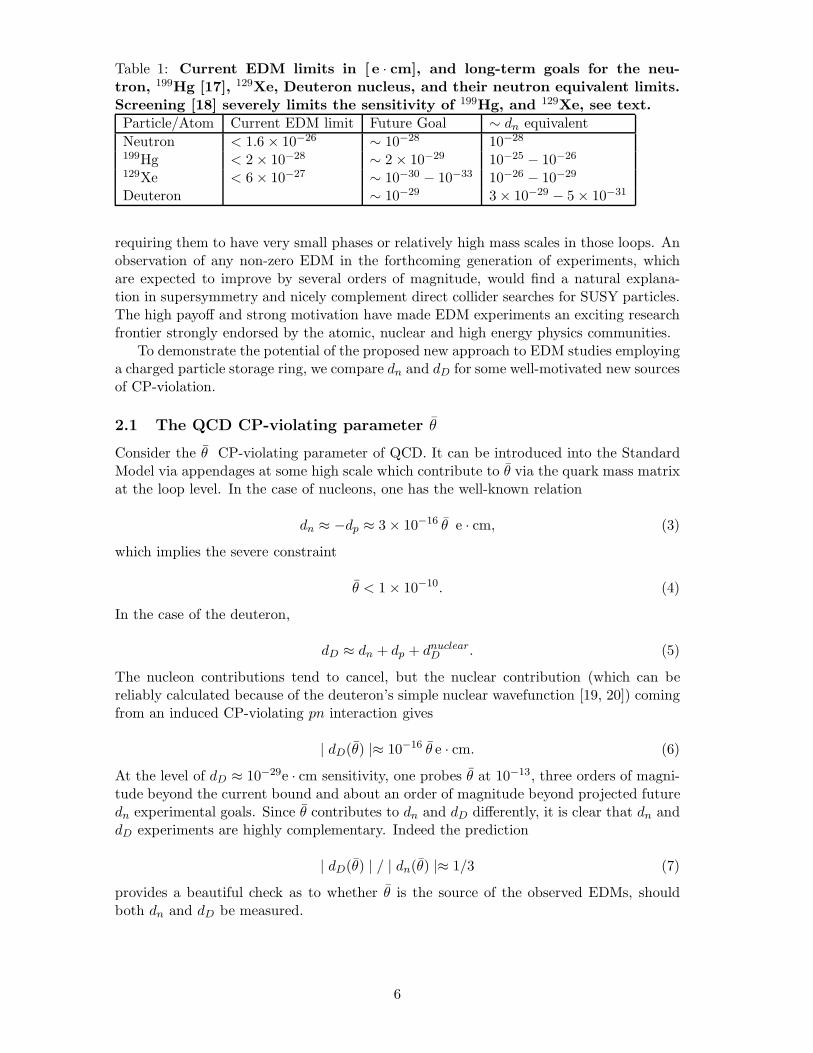
Table 1: Current EDM limits in [ e · cm], and long-term goals for the neu-tron, 199Hg [17], 129Xe, Deuteron nucleus, and their neutron equivalent limits.Screening [18] severely limits the sensitivity of 199Hg, and 129Xe, see text.Particle/Atom Current EDM limit Future Goal ∼ dn equivalentNeutron < 1.6 × 10⁻²⁶ ∼ 10−28 10−28
199Hg < 2× 10⁻²⁸ ∼ 2× 10⁻²⁹ 10−25 − 10−26
129Xe < 6× 10⁻²⁷ ∼ 10−30 − 10−33 10−26 − 10−29
Deuteron ∼ 10−29 3× 10⁻²⁹ − 5× 10⁻³¹
requiring them to have very small phases or relatively high mass scales in those loops. Anobservation of any non-zero EDM in the forthcoming generation of experiments, whichare expected to improve by several orders of magnitude, would find a natural explana-tion in supersymmetry and nicely complement direct collider searches for SUSY particles.The high payoff and strong motivation have made EDM experiments an exciting researchfrontier strongly endorsed by the atomic, nuclear and high energy physics communities.
To demonstrate the potential of the proposed new approach to EDM studies employinga charged particle storage ring, we compare dn and dD for some well-motivated new sourcesof CP-violation.
2.1 The QCD CP-violating parameter θ
Consider the θ CP-violating parameter of QCD. It can be introduced into the StandardModel via appendages at some high scale which contribute to θ via the quark mass matrixat the loop level. In the case of nucleons, one has the well-known relation
dn ≈ −dp ≈ 3× 10⁻¹⁶ θ e · cm, (3)
which implies the severe constraint
θ < 1× 10⁻¹⁰. (4)
In the case of the deuteron,
dD ≈ dn + dp + dnuclearD . (5)
The nucleon contributions tend to cancel, but the nuclear contribution (which can bereliably calculated because of the deuteron’s simple nuclear wavefunction [19, 20]) comingfrom an induced CP-violating pn interaction gives
| dD(θ) |≈ 10−16 θ e · cm. (6)
At the level of dD ≈ 10−29e · cm sensitivity, one probes θ at 10−13, three orders of magni-tude beyond the current bound and about an order of magnitude beyond projected futuredn experimental goals. Since θ contributes to dn and dD differently, it is clear that dn anddD experiments are highly complementary. Indeed the prediction
| dD(θ) | / | dn(θ) |≈ 1/3 (7)
provides a beautiful check as to whether θ is the source of the observed EDMs, shouldboth dn and dD be measured.
6

2.2 Supersymmetry
Supersymmetry (SUSY) and the new particles associated with it (sparticles) are generallyconsidered to be a very possible extension of the Standard Model. Generic predictionsof such a scenario include a plethora of new particles which may be discovered at theLHC and new CP-violating phases that can generate EDMs for quarks, leptons and theirassociated bound-states. In fact, existing EDM bounds already severely constrain theparameter spaces of SUSY models. The next generation of EDM experiments has anextremely good chance of yielding positive results if SUSY turns out to be correct.
Below, we use SUSY as a way of comparing dD with other EDM studies, primarilydn, which is expected to be pushed to about 5× 10⁻²⁸ e · cm in the coming generation ofexperiments.
Following the work of Lebedev et al. [21] and the review article by Pospelov and Ritz[22], we note that SUSY loops give rise to ordinary quark EDMs, dq, as well as quark-colorEDMs, dc
q. One finds
dn ≈ 1.4(dd − 0.25du) + 0.83e(dcd + dc
u) + 0.27e(dcd − dc
u), (8)
where the color EDM contribution has been divided into isoscalar and isovector parts.Currently, the experimental bound on dn suggests for color EDMs
|e(dcd + dc
u)| ≤ 2× 10⁻²⁶ e · cm (9)
|e(dcd − dc
u)| ≤ 6× 10⁻²⁶ e · cm. (10)
Almost an order of magnitude better bound on the isovector component comes from 199Hg
|e(dcd − dc
u)| ≤ 2× 10⁻²⁶ e · cm. (11)
Those constraints are already quite stringent. In the case of dn, they are expected to bepushed by two orders of magnitude in the long term.
Now consider the SUSY prediction for the deuteron,
dD ≈ (dd + du) + 6e(dcd − dc
u)− 0.2e(dcd + dc
u). (12)
Comparing dD with dn in Eqs. (8, 12) illustrates a significant advantage of dD. It is about20 times more sensitive to the isovector component e(dc
d−dcu) than dn because of the large
two body, I = 1, pion exchange contribution. At a dD sensitivity of 10−27 e · cm (the oldproposal goal), the bound on e(dc
d − dcu) in Eq. (10) is extended by 2 orders of magnitude
and is more than an order of magnitude better than the ultimate goal of dn experiments.It is much better than 199Hg capabilities and, of course, much cleaner theoretically. WhendD is pushed to 10−29 e · cm (our present goal), those constraints are extended by anothertwo orders of magnitude, a remarkable capability. In the case of quark EDMs and theisoscalar combination e(dc
d + dcu), a sensitivity of dD to 10−29 e · cm is still more than an
order of magnitude better than the best dn expectations. It is clear that dD is not onlycomplementary to other EDM searches, but for some potential sources of EDMs, it issuperior.
To put the above dD sensitivities into perspective, we consider the results of Lebedevet al. [21] for some specific SUSY models. At dD ≈ 10−27 e · cm, SUSY squark masses wellbeyond 10 TeV are probed, i.e., beyond LHC capabilities. At 10−29 e · cm, one exploresscales extending beyond 100 TeV, a very impressive sensitivity.
7

2.3 Dimensional Analysis
To roughly estimate the scale of “New Physics” probed by EDM experiments, we oftenassume on dimensional grounds
di ≈ mi
Λ2e sinφ, (13)
where mi is the quark or lepton mass, sinφ is the result of CP-violating phase, and Λ isthe “New Physics” scale. For mq ∼ 10 MeV and sinφ of order 1/2, one finds
dD ∼ 10−22
(1TeV
Λ
)2
e ·cm. (14)
So, dD ∼ 10−29 e ·cm sensitivity probes Λ ∼ 3000 TeV. More realistically, the di generallyresults from a quantum loop effect and there is a further g2/16π2 ∼ 1/100 suppression.So, for example, in supersymmetry one might expect
dD ∼ 10−24
(1TeVMSUSY
)2
sinφ e ·cm. (15)
In such a theory, with MSUSY ≤ 1 TeV, sinφ would have to be very small, ≤ 10−5 ifa dD ≥ 10−29 e · cm were not observed. Of course, one hopes that the LHC may actuallyobserve squarks in the TeV or lower range and that sinφ ≥ 10−5. If that is the case, dD
will provide precise EDM measurements that will unveil their CP-violating nature andperhaps help to explain the matter-antimatter asymmetry of our universe.
Other new models of CP-violation from Left-Right symmetric gauge theories, addi-tional Higgs scalars, etc. can also be studied using EDM experiments. In such cases, dD
at 10−27 e · cm is competitive with or better than other EDM measurements, while at10−29 e · cm it is our best hope for finding new sources of CP-violation. Couple that sensi-tivity with the relative theoretical simplicity of the deuteron wavefunction for calculatingdD and it becomes clear that the deuteron EDM holds great discovery potential and thestorage ring method should therefore be vigorously pursued.
3 Concept of Experiment
3.1 Overview of the Experimental Technique
In our proposed experiment, the EDM of D+, the bare deuteron nucleus is directly probedusing a storage ring technique which has the potential to increase the sensitivity of EDMmeasurements by several orders of magnitude. Longitudinally polarized deuterons are firstinjected into a storage ring. During the storage time, we probe the spin precession in boththe “horizontal” and “vertical” directions by polarimetry, detecting deuterons scatteredby solid carbon targets. For a particle at rest, an EDM couples to the electric field and amagnetic moment couples to the magnetic field. Since a relativistic particle in a magneticstorage ring feels both magnetic and electric fields in its rest frame, its spin precessionvector will be modified by the presence of an EDM. This was recognized early on [23] andthis method was applied to set limits on the muon EDM [24]. The EDM signal is a changein the “vertical” polarization, with time given by
ΔPV = Pωedm
Ωsin(Ωt+ θ0), Ω =
√ω2
edm + ω2a, (16)
where P is the polarization of the particle beam, and ωa, ωedm are the precession fre-quencies arising from the magnetic and electric dipole moments, respectively. ωa is the
8
“horizontal” precession frequency measured in g-2 experiments. ωedm is a “vertical pre-cession” which would tip the usual g-2 precession out of the horizontal plane. In ourexperiment, we maximize the change in the “vertical” polarization during beam storageby applying a radial E-field [2, 25], and reduce ωa by a factor of more than 109. ThenΩ t < 1 at all times up to 103 s, and, for small θ0, the term sin(Ωt + θ0) � Ω t + θ0.Therefore ΔPV (t) � P ωEDM t, i.e., canceling ωa to ≥ 109 amplifies the maximum valueof ΔPV (t) by 109.
The storage ring provides a clean environment with intense, highly polarized, andstable beams of low emittance. The dominant systematic errors of the traditional neutralparticle EDM search techniques are absent, or highly suppressed. First we discuss theproblems inherent in the traditional neutral particle EDM experimental method, andthen introduce the new storage ring method. The spin precession for a particle at rest,�v = 0, is:
d�S
dt= μS × �B + dS × �E, (17)
where the magnetic moment μ = ge/2mc, d is the electric dipole moment, S = �S/S, withS the spin quantum number. For the neutron, e/m of the proton is used; and gn = −3.8.Neutron EDM experiments have been ongoing since the 1950s [26]. The experimentshave been performed in a weak magnetic field, typically 1 μT, and a strong electric field,typically 2 MV/m. The spin precession frequency is measured with the electric fieldparallel and anti-parallel to the magnetic field. A change in the measured spin precessionfrequency would be evidence for an EDM.
A systematic error can originate from any stray magnetic field, such as one caused byleakage currents from the electric field electrodes that changes sign when the electric fieldis flipped. In a real neutral particle EDM experiment with |�v| � c, the spin precession isgiven by
d�S
dt= μS ×
(�B − �v × �E
)+ dS ×
(�E + �v × �B
). (18)
The μ(S× (�v× �E)) term represents a systematic error in the EDM search since this term,like the EDM precession term, changes sign when the electric field changes sign. Notethat the d(S × (�v × �B)) term increases the EDM signal, but it is negligible compared tothe electric field term.
Next we discuss the situation for a relativistic particle in a storage ring [27] wherethere are both magnetic and electric fields. The spin precession due to the magneticdipole moment is:
d�S
dt=
e
m�S ×
[(a+
1γ
)�B − a γ
γ + 1
(�β · �B
)�β −
(g
2− γ
γ + 1
) �β × �E
c
], (19)
where a = (g − 2)/2 is the anomalous magnetic moment. The spin precession due to theelectric dipole moment is simply:
d�S
dt= d
[S ×
(c�β × �B + �E
)]. (20)
The d S × �E term can be neglected in the above equation, since this change in the EDMsignal is small compared to the magnetic field term. The spin precession due to the electricdipole moment is about the �β × �B vector.
9
For the simple case of �β · �B = �β · �E = 0, the precession of the spin direction relativeto the momentum direction is given by �ω = �ωa + �ωedm, where
�ωa =e
m
[a �B +
(1
γ2 − 1− a) �β × �E
c
](21)
is the rotation about the vertical ( �B-field direction) direction that arises because there isan anomalous part to the magnetic moment. The frequency about the radial direction(for a spin one particle S = 1) is
�ωedm = dc
hS
(�E
c+ �β × �B
), (22)
which comes from the torque produced on the EDM. The EDM signal is an increasinglyvertical polarization produced by a non-vanishing ωedm precession. The change in thevertical polarization with time is given in Eq. (16). Thus, it behooves us to minimize ωa,although for systematic error management ωa should be small but not zero. This can bedone by applying a radial electric field of magnitude
Er =aBcβγ2
1− aβ2γ2� aBcβγ2 (23)
to cancel the a �B contribution to ωa in Eq. (21) [2, 25]. A sensitive EDM search requireslarge electric fields and particles with a small anomalous moment.
Unfortunately, there are no particles with a = 0. Leptons have a � 0.001. Theelectron imposes difficulties using the storage ring technique since it generates a largeamount of synchrotron radiation, which introduces an additional systematic error: anelectron beam in a storage ring develops a polarization component along the direction ofthe magnetic field vector. The situation is much better for the muon since synchrotronradiation intensity falls as 1/m4. An LOI has been submitted to JPARC [28] for a muonEDM experiment at the level of 10−24 e · cm statistical and orders of magnitude lowersystematic error. The statistical error is large because of the difficulty of obtaining asufficient flux of stored muons; the muon beam derives from a secondary pion beam andis created with very large emittance. Its lifetime also limits the time for observing theEDM precession. The challenge of a MW proton beam creating an intense muon beammeans that this experiment is at least one decade away from physical realization. Thusother cases that can reach the same level of sensitivity in a shorter time are preferred.
The deuteron is an ideal candidate. It has a small anomaly, a = −0.143. Intense, low-emittance beams with high polarization and efficient polarimeters are readily available.We are proposing here a search for the deuteron EDM with statistical error of 10−29 e ·cmand systematic error of less than 10−29 e ·cm.
The EDM systematic error due to a weak magnetic field induced by leakage currentsfrom the electric field electrodes is negligible since the storage ring magnetic field is strong(� 0.5 T), not weak (� 10−6 T), as in the neutral beam EDM experiments. Furthermore,in the storage ring EDM search, the �v × �E precession term is not a systematic error, butrather a tool to control the g − 2 precession rate to increase the statistical sensitivity tothe EDM. In order to control systematic errors, the g − 2 precession rate is varied, asdiscussed later.
We have extensively studied spin dynamics systematic errors [2] and have found onlyone first-order spin dynamics systematic effect for the Storage Ring EDM experiment: if
10
there is a non-zero average value for the vertical component of the electric field, 〈EV 〉 ≡〈�E · �B〉/B �= 0, then the spin will precess about the radial direction:
ωsyst � μ〈EV 〉βcγ2
. (24)
This effect, relative to the EDM effect, changes sign when we inject the beam clock-wise(CW) vs. counter-clockwise (CCW) into the ring. This can be seen from Eqs. (21) and (22).In going from CW to CCW, �β → −�β, �B → − �B, and �E → �E; therefore �ωa, and thus ωsyst,changes sign, while ωedm does not. Thus, conceptually, the EDM signal is separated fromfalse signals in a comparison of the measured deuteron spin precession rates about the�β × �B direction when we inject CW vs. CCW. The ratio of the spin precession (due tothe vertical electric field) to the EDM spin precession, which needs to be minimized in thedesign of the experiment, is given by
R =aμ〈EV 〉dβcE
. (25)
We have chosen for a storage ring conceptual design pD = 1 GeV/c or β = 0.5. A largervalue of β would reduce the ratio R; however, the ring cost would increase. The electricfield value E � ±120 kV/2 cm results in B � 0.5 T.
3.2 Polarimeter Design Considerations
The signal of an EDM is a changing vertical component of the stored beam’s polarization.Measuring such a change requires continuous monitoring of that component during thetime that the stored beam is circulating in the ring, and looking for a particular timedependence associated with the lifetime of the stored beam. The most efficient polariza-tion monitor is scattering from a nucleus where the sensitivity to the amount of verticalpolarization is given by the spin-orbit part of the strong nuclear interaction between thedeuteron and the target nucleus. Thus, the polarimeter must be able to sample the storedbeam over time and, with high efficiency and extremely low systematic error, scatterdeuterons (or other particles) into angles where they are easily detected using standardparticle tracking technology.
In this section, we begin with a brief discussion of the design requirements for the po-larimeter and the ways that we are investigating the management of systematic errors dueto position and angle misalignments of the beam. These errors are the subject of a pro-posal that was submitted to the Program Advisory Committee for the Cooler Synchrotron(COSY) storage ring at the Forschungszentrum-Julich. Eight weeks of beam time havebeen approved for proof-of-principle studies and the collection of more deuteron-carbonscattering and reaction data to be used for polarimeter simulations. At this time the firstrun is scheduled for June, 2008, to set up new electronics for our work and to investigateissues surrounding efficient running of an EDM polarimeter. After discussing these issues,we review the way in which we plan to run with the EDM storage ring, and show a simpleillustration of the data we expect to obtain.
Since 2004, we have also had approved beam time for polarized deuterons at the KVIcyclotron in Groningen. At first, this time was used for the measurement of a broadrange of elastic scattering and reaction products that we expected to see in our final EDMpolarimeter. More recently, data have been taken on the sensitivity of deuteron-carbonreactions to position and angle errors in the beam. These results will be discussed below.
11
3.2.1 Polarimeter Design
In the region below 250 MeV, the best sensitivity to vector polarization is forward-angleelastic scattering. In general, this sensitivity is described by the vector and tensor po-larizations that are possible using a spin-1 beam along with their analyzing powers thatcontain the sensitivity of the scattering or reaction process to those polarizations. Thissensitivity is given by:
σpol = σunpol (1 + 2 it11 iT11 + t20 T20 + 2 t21 T21 + 2 t22 T22) , (26)
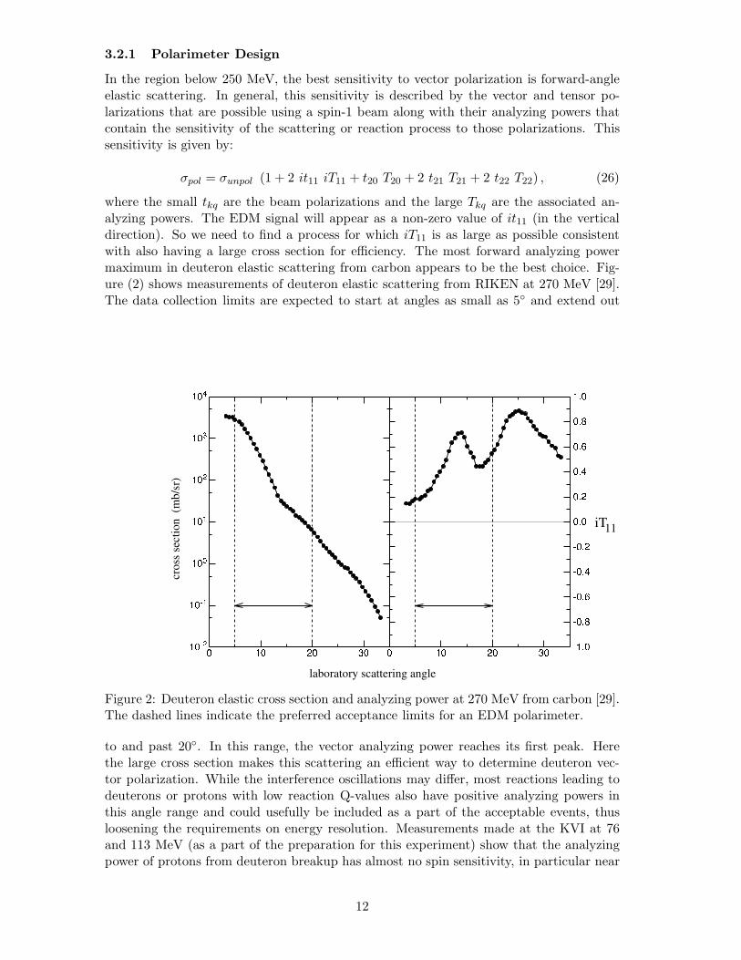
where the small tkq are the beam polarizations and the large Tkq are the associated an-alyzing powers. The EDM signal will appear as a non-zero value of it11 (in the verticaldirection). So we need to find a process for which iT11 is as large as possible consistentwith also having a large cross section for efficiency. The most forward analyzing powermaximum in deuteron elastic scattering from carbon appears to be the best choice. Fig-ure (2) shows measurements of deuteron elastic scattering from RIKEN at 270 MeV [29].The data collection limits are expected to start at angles as small as 5◦ and extend out
Figure 2: Deuteron elastic cross section and analyzing power at 270 MeV from carbon [29].The dashed lines indicate the preferred acceptance limits for an EDM polarimeter.
to and past 20◦. In this range, the vector analyzing power reaches its first peak. Herethe large cross section makes this scattering an efficient way to determine deuteron vec-tor polarization. While the interference oscillations may differ, most reactions leading todeuterons or protons with low reaction Q-values also have positive analyzing powers inthis angle range and could usefully be included as a part of the acceptable events, thusloosening the requirements on energy resolution. Measurements made at the KVI at 76and 113 MeV (as a part of the preparation for this experiment) show that the analyzingpower of protons from deuteron breakup has almost no spin sensitivity, in particular near
12

the peak of the breakup cross section distribution in outgoing energy. Excluding theseevents from the polarimeter acceptance will improve performance.
A critical parameter in the design of the polarimeter is the accumulation of a largestatistical sample throughout the beam store. Compared to the extremely thin targetsthat typically are used to intersect a stored beam, it is essential that as far as possibleeach deuteron traverses the maximum amount of carbon material (between 4 and 6 cm) foreach encounter with the target. We propose to place a target with this thickness and cutas a smooth edge near the beam. If it is close enough to the beam, this edge will becomethe defining aperture for the entire EDM storage ring. In this case, any deuterons lostfrom the ring due to interactions with the background gas in the vacuum will eventuallybe lost from the stored beam by hitting this target. Targets of comparable thickness havebeen used at Saturne for measuring deuteron polarization ([30] and references therein).Polarimeter efficiencies of a few percent characterize this work.
Beam time has been approved for June 2008 for COSY-Julich to investigate what isthe best configuration for such a target. Carbon samples in the form of both a tube (withthe beam going through the center) and a 2-mm thick edge that comes close to the beamon one side have been prepared. The edge target will eventually intercept all deuteronswith a betatron amplitude that exceeds the distance from the central closed orbit to theedge. Thus, effectively all of the beam can eventually be removed on such a target.
The emittance of the beam will slowly increase due mainly to Rutherford scatteringwith the residual gas atoms in the vacuum chamber. Calculations which include both largeangle single and multiple small angle collisions indicate that 10−11 Bar vacuum pressurewill give the desired rate on the Carbon target. For the tests at COSY, we plan to haveavailable the ANKE cluster jet target, so that controlled studies can be made of the lossrates and beam lifetime.
The efficiency of this scheme depends on the way in which the front face of the carbontarget is illuminated. Single Coulomb scattering from residual gas may produce averagedepths of a few millimeters, more than enough to prevent sideways re-emergence of thebeam from multiple scattering. Deuterons that enter close to the edge may exit throughthe surface close to the beam or produce breakup protons, leading to events with an energyhigher than those that must pass through the full target thickness. This may increase thefraction of events composed of protons from deuteron breakup. The work at COSY willprovide data on this process. The tube target was intended to provide uniform coveragefrom all sides of the beam, but creates difficulties if, during the store, the beam becomesunbalanced on the left and right sides. The edge target solves this problem since all eventsemerge from one point, but with the feature that left and right exposure to the inner targetface is asymmetric. Systematic polarization errors from both will be measured at COSY.
3.2.2 Polarimeter errors
We plan to have multiple deuteron beam bunches circulating in the EDM ring at the sametime with opposite states of polarization. This is one of the most common ways of rejectingsystematic errors due to detector acceptance differences. If L and R denote the countingrates in the left and right detectors, the vector asymmetry for + and − polariation statesis given by
εLR = 2 it11 iT11 =r − 1r + 1
r2 =L+R−L−R+
. (27)
If the spin-sensitive scattering process is nominally symmetric for perfect beam align-ment in the polarimeter, then this scheme cancels first-order errors from beam misalign-ment in position and angle. However, second-order effects exist. If the misalignment
13
is characterized by an angle θ and the polarization up-and-down bunches have differentpolarizations (denoted by u = p+ + p− where p− < 0), then the asymmetry is changed by
ε← ε+1
1− ε2[ε3u2 + 2ε2
∂iT11
iT11∂θuθ + ε
(∂2iT11
iT11∂θ2(1− ε2)−
(∂iT11
iT11∂θ
)2
ε2
)θ2
]. (28)
Here the ε on the right hand side is likely not the EDM signal but a steady backgroundthat is a residual of the beam polarization preparation process (and which will probablynot be set to zero better than a few parts per thousand). The most severe constraintson beam stability early to late in the store are generated by the θ2 term. Using valuesof the logarithmic derivatives of the analyzing power based on elastic scattering, keepingthe errors below 10−29 e · cm requires angle shifts less than 0.1 mrad and position shiftsless than 0.1 mm for a 1-m deep polarimeter construction. For the tube target design, aposition shift can amplify such systematic effects since it modulates the illumination of theleft and right sides of the opening. The edge target eliminates this ambiguity, but has theproblem that the scattering is not nominally left-right symmetric, a source of first-ordererrors. These effects will be investigated in more detail at COSY.
Error studies using the In-Beam Polarimeter (IBP) at the KVI cyclotron in Gronin-gen looked specifically at the possibility to measure the second-order errors of Eq. (28).The results for a deuteron scattering angle of 18◦ are shown in Fig. (3). The quality ofagreement in both curvature (θ2 term) and slope (uθ term) is excellent and confirms theuse of such a Taylor series analysis for understanding quantitatively the polarimeter er-rors. Development of the models on which these predictions were based is continuing, andeventually will be added to simulations of the EDM target configuration to make muchmore precise predictions of polarimeter performance.
One consequence of this study for the design of the polarimeter is the necessity, if weuse a tube target, of monitoring the relative flux from all sides of the target. One possibledetector design involves placing segmented plastic scintillators that cover the range ofscattering angles from 10◦ to 20◦ behind iron absorbers [31] (1.5 − 2.0 cm), a schemethat was used in this energy range for deuteron polarization transfer measurements atSaturne. We are considering replacing this concept with a micro-megas-TPC [13] whosetracking ability would allow us to know about changes that would alter the illuminationof the sides of the tube. If we feel that we need the constraints of an edge target, then itwill become necessary to distinguish breakup protons from deuterons, a job that can beaddressed using dE/dx measurements or TOF measurements with a multi-resistive platechamber [12].
For the EDM storage ring, a polarimeter could be located in one of the two straightsections between quadrupole magnets. A target placed near the exit of one quadrupolewould allow scattered particles to emerge from a 5-cm diameter beam pipe and pass intoa detector before reaching the next quadrupole.
For the design of the EDM polarimeter, additional broad range data covering deuteronscattering and breakup are needed at energies above those available at the KVI. For thispurpose, the proposal to COSY-Julich also requested time on the WASA detector usinga solid carbon target (not yet available) to measure the necessary spectra and their spindependence at a variety of energies up to 250 MeV. This time is approved but not scheduledawaiting work on the design of a solid target assembly to operate with the WASA detector.
3.2.3 Running cycle
In the actual search for an EDM, vertically polarized deuteron beams will be loadedinto both the CW and CCW storage rings. Bunching will be managed by an RF cavity.
14

displacement (mm)
ε
Cross Ratio (18°)
-6 -4 -2 0 2 4 6-0.141
-0.140
-0.139
-0.138
-0.137
-0.136
Figure 3: Measurements of the change in left-right asymmetry as the target position ismoved horizontally. The solid line is an a priori prediction based on the older scatteringmeasurements at 113 MeV. The curve has been offset vertically to match the averageasymmetry. The errors shown are statistical only and do not include effects due to thesetup of the beam position shifts and other systematic considerations.
Subsequent bunches will have opposite polarization directions. Sometimes unpolarizedcontrol bunches will be used.
Once all beams are in the ring, solenoids along each ring will be turned on for ashort time to precess these polarizations into the horizontal plane. The solenoids neednot be operated at some frequency since, with the electric field, the g − 2 precessionwill be negligable during the time that they are on. The completion of this step startsthe running for that store. The polarimeter will operate continuously, monitoring thevector (and tensor) polarization components. The beam will be dumped when either thepolarization is too low or the current is too low. The process will be repeated, but withthe magnetic fields of the storage rings reversed (leaving the electric fields intact). Theinjection directions for the upper and lower rings will be exchanged, reversing the roles ofCW and CCW.
Data from all parts of this running cycle will be combined to cancel contributions fromsystematic errors that do not flip with polarization state or have a time-reversal conservingdependence on the direction of the beam in the storage rings.
15

3.2.4 Producing a Polarized Beam and What is Observed
A polarized ion source for spin-one deuteron beams changes the fraction, f1, f0, or f−1, ofthe beam that is in each of the three magnetic substates away from the unpolarized valuesof f1 = f0 = f−1 = 1/3. This can produce a vector polarization (pV = f1 − f−1) and/ora tensor polarization (pT = 1 − 3f0) with respect to the orientation of the quantizationaxis established by the magnetic field in the ion source. High statistical sensitivity to theEDM requires that the vector polarization be as large as possible, or f1 ∼ 1. In this caseboth f0 and f−1 are close to zero and there is also a maximally large and positive tensorpolarization. One secondary effect of this choice is that when the projection of the beamquantization axis onto the plane of the storage ring does not lie along a coordinate axis(either x or z), a left-right asymmetry is introduced that must be distinguished from anEDM signal.
A thorough knowledge of the polarization components requires that we detect particlesat a variety of angles (θ, φ) where θ is the polar angle measured from the momentumdirection and φ is the azimuthal angle that starts from the left (facing along the beammomentum) in the g − 2 precession plane and advancing in the clockwise direction. Theorientation at the scattering target of the quantization axis produced by the polarized ionsource is a result of the cumulative effect of the transport line and ring electromagneticfields. Its orientation when it reaches the polarimeter target is specified by a second set ofspherical angles (ξ, ψ) with respect to the same reference frame. For a particle emergingfrom the target at (θ, φ), the differential cross section is modified according to
σ(θ, φ) = σunp(θ) [1 + 2 it11 iT11(θ) + t20 T20(θ) + 2 t21 T21(θ) + 2 t22 T22(θ)] , (29)
where the Tkq(θ) are the analyzing powers of rank k (k = 1 is vector, k = 2 is tensor) andthe tkq are the corresponding beam polarizations that are given by
it11 =√
32
pV sin ξ sin(ψ − φ)
t20 =1
2√
2pT (3 cos2 ξ − 1)
t21 = −√
32pT sin ξ cos ξ cos(ψ − φ)
t22 =√
34
pT sin2 ξ cos 2(ψ − φ) .
(30)
The small vertical spin component that signals the presence of an intrinsic EDM ap-pears as a left-right asymmetry through the it11iT11 term in Eq. (29) because pV is large(∼ 0.8) and ψ − φ = ±π/2 maximizes sin(ψ − φ). This happens with the opposite signon the left and right sides of the beam when the vertical component makes ψ = ±π/2.Such an asymmetry can also arise through the t21T21 term if pT �= 0 and ψ − φ ∼ 0 orπ. This situation arises naturally if the anomalous precession is not cancelled to an ex-tremely high precision (less than 1 part in 1012 for 10−29 e·cm) that we in practice cannotachieve. However, if the deuteron in-plane polarization were allowed to precess slowly (byvirtue of the fact that the sizes of the electric and magnetic fields are slightly differentfrom the condition that freezes the polarization direction) with an angular velocity ωa, theprecession can be tracked and used to separate various contributions to the polarizationmeasurement that are unrelated to an EDM, exposing the signal of interest. One candistinguish the EDM and t21 effects by measuring the vertical polarization component asa function of time. An analysis would separate the sin ξ from the sin ξ cos ξ = (sin 2ξ)/2dependence provided ξ was allowed to vary by a large enough angle such as π. In general,
16
there are a number of systematic sources of a left-right asymmetry, such as a vertical po-larization in the injected beam, misalignments of the beam at the polarimeter, non-lineardetector response, and magnetic field errors that produce non-commuting rotations as thebeam circles the ring. The time-dependent analysis is crucial for extracting the sin ξ termassociated with an EDM.
In addition to the changes in the observed polarization that are a consequence of ξchanging with time, we expect that the magnitude of the polarization itself will be decliningexponentially as the deuterons within the beam slowly respond to different phase spaceconditions within the beam. Since the tensor polarization reverses after a quantizationaxis rotation of only π/2 rather that π, it will depolarize with a time constant that is halfof the vector polarization time constant [32].
The polarimeter data from the EDM search will consist of a set of deuteron polariza-tion components measured as a function of the time during the store while the polarizationslowly precesses (ωa �= 0). Three possible asymmetries are shown in Fig. (4) as a functionof time in a 100-second beam store (top panels) in which the polarization coherence timeis 200 s. Initially, the beam polarization is sideways (along the positive x axis, maximiz-ing εDU) and the rotation begins toward the beam momentum direction. The left-rightasymmetry εLR is only one of the observed polarization components. The largest is thedown-up asymmetry εDU (2it11〈iT11〉 > 0.5) from the horizontal component of the vectorpolarization. The t22 tensor polarization produces another asymmetry ε22 that makes thesum of down and up rates different from the sum of left and right rates. This asymmetryis at a level of 0.03. There is a tensor contribution to the left-right (EDM) asymmetrythat comes from the t21 beam polarization. This asymmetry is at the level of 0.02. Thissignal has a period in ξ that is half that of the EDM signal (greatly enhanced in thissimulation and shown as the short dashed line in the upper middle panel), a feature thatmay be used to separate this contribution.
An analysis of the EDM data requires the use of a model that carries these features aswell as others not covered here. Thus, the EDM signal is more than a simple asymmetry.It is (1) a time-varying polarization component associated with sin ξ whose maximum
size (2) varies as ωedm/√ω2
edm + ω2a and (3) has the correct behavior with respect to
various reversals that are built into the running plan. These reversals include change ofthe vector polarization sign (by solenoid field change or source RF transition), change ofbeam revolution direction (CW or CCW), and change of sign of the uncancelled anomalousprecession (ωa). In addition, the time dependence of the EDM signal must be the integralof the longitudinal component of the vector polarization, beginning with zero as the storestarts. For measurements which differ only in the sign of ωa, time reversal violationrequires that the EDM signal also change sign, a feature that separates it from manyother systematic effects. This can be deduced in the presence of depolarization by usingthe tensor contributions to the asymmetry to separate different components and to locatethe direction of the vector polarization in space. Note that as the beam depolarizes, thisEDM-related oscillation also grows smaller with time and in this case does not ever crosszero except at the start.
Inherent in this scheme is the use of down-up and tensor asymmetries to set the timewhen the polarization vector passes above or below the momentum direction so that thezero point for ξ is known. In cases where ωa is not constant with time, looking at thecorrelations between asymmetries can yield EDM signatures that are independent of ωa.The bottom panels of Fig. (4) show two correlations in which the signal without an EDMpiece is shown by the long-dashed lines. For εDU versus εLR, the EDM produces a tilt ofthe pattern. (The absolute horizontal shift is a function of when the data-taking startsand is not in itself an EDM effect.) Likewise, similar horizontal shifts are present in the
17

εLR εLR
εDU ε22
εDU εLR ε22
time (s)
-0.03 -0.01 0.01 0.03-0.6
-0.2
0.2
0.6
-0.03 -0.01 0.01 0.03-0.03
-0.01
0.01
0.03
0 20 40 60 80 100-0.6
-0.2
0.2
0.6
0 20 40 60 80 100-0.03
-0.01
0.01
0.03
0 20 40 60 80 100-0.03
-0.01
0.01
0.03
Figure 4: The polarimeter asymmetries as a function of time in the beam store. Theshort dashed curve in the upper middle panel represents the EDM signal alone. The longdashed correlation curves in the lower panels contain no EDM effect.
correlation of ε22 with εLR and may be used to confirm any EDM observation. Withoutan EDM, a smooth spiral results.
For a sensitivity to an EDM at the level of 10−29 e ·cm, we need to detect a change inεLR of about 5× 10⁻⁶ for the smallest practical values of ωa.
3.3 Statistical Accuracy
An estimate of the time required to reach a sensitivity of 10−29 e · cm must consider thatthe beam itself is being used up and the polarization is decreasing exponentially. A simpleestimate can be made for polarization that is initially fixed along the momentum of thebeam. An optimization gives the best result for a measurement time that is equal to thepolarization lifetime, and a beam lifetime that is half of the polarization lifetime. In thiscase the one standard deviation error on d is
σd ≈ 8h√τp (βcBV − ER) ıt11〈ıT11〉
√NcfTtot
. (31)
For a ring with momentum p = 1 GeV/c and polarization lifetime τp = 103 s, we useER = 12 MV/m, BV = 0.5 T, and Nc = 2× 10¹¹ deuterons/fill. The polarimeter has anefficiency of f = 0.01 and an effective asymmetry of 2 it11〈iT11〉 = 0.36. The time neededto reach an error of σd = 10−29 e ·cm is about Ttot = 107 s.
We request running time for 6 months for commissioning the ring and another 6 monthsfor the first measurement. Most of the first 6-months’ running time will go toward theinvestigation of systematic errors. In particular, measurements will be made at multiple
18
values of ωa to learn whether the sin ξ Fourier component has a strength that varies asωedm/
√ω2
edm + ω2a. We wish to take this running time over a span of two years.
With 1011 deuterons/fill/ring, the maximum possible polarimeter rate is∼ 108 events/swith 100% detection efficiency. We will use either current-mode sampling as the method ofdetector readout or single particle detection. The current mode has worked well for recentparity-violation experiments where the asymmetry associated with the signal is small [33].The alternative method we are investigating is to use single particle detection with adetector that can operate well in a high-rate environment, such as the micro-megas [13].
4 Deuteron Storage Ring
4.1 Lattice Design Considerations
The conceptual elements of the proposed EDM ring are given in Table 2 and Fig. 5.They are defined by the choice of deuteron momentum acceptable for efficient deuteronpolarimetry (pD = 1.0 GeV/c), the readily attainable magnitude of the electric fieldat the chosen 2 cm distance between electrodes (ER = 12 MV/m), and the free spacebetween lattice elements needed for the chosen number of polarimeters (4). In addition,the CW-CCW procedure to cancel the EV -field effect requires that the periodic sequenceof the fields, �E(s), �B(s), met by the particles moving clockwise be the same as the periodicsequence of the fields, �E(−s), − �B(−s), met by the particles moving counterclockwise. The�E-field is always directed outwards. The minimization of the second-order perturbationsimitating the EDM requires that the magnetic field, BV , of any bending magnet not beseparated in space from the radial electric field, ER, which we use for cancellation of theg − 2 rotation in this magnetic field.
Table 2: Deuteron EDM ring parameters
Deuteron Momentum 1.0GeV/cRigidity, (B − E/β)R 3.336 TmElectric field, ER, for 2ax = 2cm 12MV/m (0.04 T)Magnetic field, BV 0.4819 TLength of orbit, L 82.955mBE− section radius, R0 8.4058 mLength of the BE− section, lBE 3.3009 mNumber of regular periods, N 8Horizontal tune, νx = fx
fc4.2520
Vertical tune, νy = fy
fc3.8019
Betatron amplitude functions, (βx,y)max 11.704 m; 13.256 mDesigned injected εx,y = πa2
x,y/(βx,y)max 3πmm mr; 10πmm mrMomentum compaction factor, α 0.217(Δp/p)max 10−3
Quad gradient in bending section, B′g, for lg = 0.3 m 370.6 Gauss/cm
Quad gradient in straight section, lg = 0.3837 m 1174 Gauss/cmNumber of long straight sections, Ns.s. 2Number of free intervals in one straight section 8
Inside the BE sections, B = BV is homogeneous, while E = ER = E0R0R = E0
1+x/R0,
where R0 = 8.406 m is the designed radius of curvature of the BE sections, E0 is the
19

radial electric field at that radius, and x = R − R0. Our design takes into accountthe corresponding small corrections of the betatron radial and synchrotron longitudinalfrequencies caused by the radial electric field. In the beam dynamics, our long straightsections are represented by unit matrices for both radial and vertical oscillations. In sucha design, our beam manipulations in the semicircles will minimally influence the beamparameters in the straight sections.
0.0 17.10 34.20 51.30 68.40 85.50Momentum offset = 0.00 %
s (m)
dEDM lattice MAD-X 3.00.01 17/04/08 13.52.39
0.0
1.8
3.6
5.4
7.2
9.0
10.8
12.6
14.4
16.2
18.0
βx(m
),βy
(m)
-3.5
-2.8
-2.1
-1.4
-0.7
0.0
0.7
1.4
2.1
2.8
3.5
Dx(m
),Dy
(m)
β x β y Dx Dy
Figure 5: The deuteron EDM ring lattice. The parallelograms on the top of the figuredepict the dipole magnetic field regions, while the thin vertical lines correspond to focusingand de-focusing magnetic quadrupoles. The red and black lines show the correspondingvertical and horizontal beta-functions as a function of the azimuthal position. The greenand blue lines show the corresponding values for the horizontal and vertical D-functionsas a function of the azimuthal position.
Special care is taken with respect to the accuracy of the same absolute value of thevertical magnetic field, |BV |, in CW vs. CCW runs. If δBV = |BV |CCW − |BV |CW �= 0,then the equilibrium radius, and hence the trajectory length of the CCW particles, differfrom those of the CW particles,
δL
L=⟨δR
R
⟩= −αδBV
BV�= 0. (32)
α = 0.2166 is the compaction factor from Table 2. Further, due to synchrotron stability,the revolution frequency, fc = βc
L , is the same for CW and CCW particles. Therefore, adeviation δL
L �= 0 leads to the corresponding deviation of the velocity,
δβ
β=δL
L�= 0. (33)
20
This, in turn, leads to an error in the cancellation of the value of EVβγ2 by the CW-CCW
method,
δ
(EV
βγ2
)∼ α
(EV
βγ2
)(δBV
BV
). (34)
This error is easily controlled by our preliminary cancellations of the vertical electricfield up to the needed level. The needed level will depend on our preliminary knowledgeof the upper limit on the dEDM. If, for example, we already know that the dEDM <3 × 10⁻²⁵ e · cm then, we will need to cancel the vertical electric field up to the levelcorresponding to that accuracy, which is EV /ER ≤ 10−10 in every fill. It is importantto note that we will not measure EV to that accuracy directly. Instead, we will measureEV indirectly by observing the vertical component of the deuteron polarization during asingle fill (lasted approximately 1000 s), and then correct EV . After that, we will havethe EV -perturbation in our ring only at that level. Then one CW and one CCW run willcancel this perturbation, if δBV /BV <150 ppm, which can be very easily achieved.
RF cavities are needed in our ring to increase the spin coherence lifetime, as explainedin the next section. Deuterons are not accelerated, but an energy loss of about 0.05 eVper turn is expected if we use the gas in the beam path to extract the beam. This energyloss will be compensated for by the electric field in the RF-cavity. We have estimated thatthis effect requires the RF-cavity to be aligned with respect to the E-field plane at the10−4 radian level, which is easily attainable.
4.2 Polarization Lifetime (Spin Coherence Time)
In our lattice design, the spin coherence time is near 1000 s. During this time,
ωa =e
m
[aBV −
(a−
(mc
p
)2)βER
](35)
is controllably small, ωa ∼ 0.001 s−1. With such a small ωa, we have no spin resonancesat the betatron and synchrotron frequencies. Nevertheless, there exist effects depolarizingthe beam. We can conclude directly from Eq. (35) that particles having different momentahave different g-2 frequencies. It is obvious also that the magnetic and electric fields metby particles depend on their betatron amplitudes. Moreover, a deeper analysis showsthat the equilibrium momenta of particles with different betatron amplitudes are alsodifferent. Thus, the undesirable depolarization effects are mostly caused by the spreadof the particles’ betatron and synchrotron deviations. In a linear approximation, in thecommonly used notation,
x(s) = 〈Δx〉+ D(s)Δpp
+Ax
√βx(s) cos (ψx(s) + δx) , horizontal (36)
y(s) = Ay
√βy(s) cos (ψy(s) + δy) , vertical (37)
Δpp
= 〈Δpp 〉+
(Δpp
)max
cos (ωLt+ δs) , momentum, (38)
where 〈Δx〉, 〈Δp/p〉 are shifts of the particle equilibrium due to the nonlinear effectsexplained below. 〈...〉 means averaging over time, and D(s) is the dispersion function. sis the longitudinal coordinate, and the synchrotron frequency ωL is much smaller thanthe betatron frequencies, νL � νx,y ≡ fx,y/fC . If the Courant-Snyder betatron functionsβx,y are given in meters, see Table 2, then the amplitudes Ax,y are measured in m1/2, andwhen, say, ymax ∼ 1.0cm, A2
y ∼ 10−5 m. Due to betatron and synchrotron oscillations, all
21

first-order (linear) spin perturbations related to the spread of x, y, and Δp/p vanish on theaverage (in time) for every individual particle. Without the synchrotron RF, momentawould not oscillate (ωL = 0), and with the spread |Δp
p | = 10−3, the beam would bedepolarized after 1 ms.
With RF cancellation of the first-order contributions to the depolarization, we turn tosecond-order effects. In the second approximation, the shifts present in Eqs. (32, 34) arenot equal to zero. This follows from the fact that, in the presence of synchrotron stability,the averaged (over time) revolution frequency is the same for all particles. Therefore,〈Δp/p〉 is connected with 〈ΔL/L〉, which, in turn, is connected with 〈Δx〉, A2
x,y, and soon.
The quadratic effects of spin decoherence time and its extension in an electron-positronstorage ring were investigated experimentally, and in part theoretically, in the BudkerInstitute [34, 35]. The results of our independent theoretical analysis are completelyconsistent with their experimental results, taking into account the difference between theirelectron-positron and our EDM deuteron storage rings. In our ring, if no special measuresare taken, then the deviation Δωa of a particle having parameters Ax, Ay, (Δp
p )max, fromthe designed ωa-value is given by
Δωa
e|a|Bm≈ (0.65m−1)A2
x + (0.16m−1)A2y + 0.84
(Δpp
)2
max
, (39)
e
m|a|B = 2π × 275.51 kHz . (40)
The spin coherence lasts nearly 1 s, when the maximal x in the beam equals 0.6 cm (εx =3π mm-mrad), the maximal y equals 0.7 cm (εy = 5π mm-mrad), and (Δp
p )max=0.001,and synchrotron stability is present. We cancel these “natural” effects by counter-effects,using different sextupole lenses in the intervals between dipoles and a small quadratic fieldcomponent inside dipoles. The cancellation accuracy 0.1% will guarantee the 1000 s spincoherence time. The magnitude of the sextupole (quadratic) B
′′fields will depend on their
distribution along the ring. We plan to have B′′ ∼ 1 Tm−2 in the dipoles and not more
than 20 Tm−2 in the lenses between dipoles.The cancellation of the quadratic terms proceeds as follows. Consider some oscillator
with a quadratic nonlinearity,d2z
dt2+ ω2z = kz2. (41)
The equilibrium position of this oscillator has the non-zero value z = 〈z〉 = k 〈z2〉ω2 , averaged
over time. This fact lies at the basis of the idea of decoherence cancellation by quadraticfields. The vertical component of a sextupole field equals
12∂2BV
∂x2(x2 − y2). (42)
Its horizontal component does not influence spin, on the average. The shift of the hori-zontal equilibrium, 〈x〉 �= 0, produced by such a field is proportional to
0.5B′′ (〈x(s)2〉 − 〈y(s)2〉) = 0.25B′′(s)
[βx(s)A2
x − βy(s)A2y +D2(s)
(Δpp
)2
max
], (43)
where all parameters are the same as in Eqs. (35)-(40). The equilibrium shift dependson a particle’s parameters and changes the length L of the trajectory of this particle.Since the rotation frequency, fC = βc/L, is fixed by the synchrotron stability, the particlemomentum is changed. These shifts change ωa. In our design, this Δωa is opposite to the“natural” Δωa.
22
4.3 Non-Commutativity of Spin Rotations Imitating the EDM Rotation
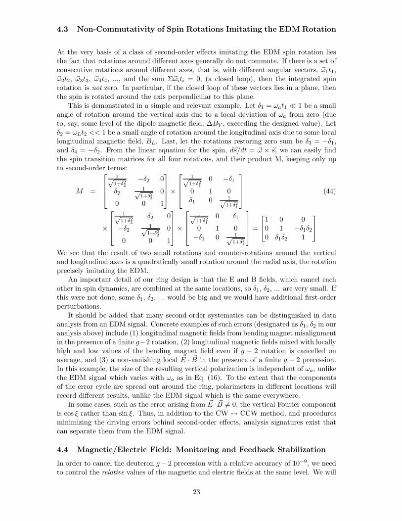
At the very basis of a class of second-order effects imitating the EDM spin rotation liesthe fact that rotations around different axes generally do not commute. If there is a set ofconsecutive rotations around different axes, that is, with different angular vectors, �ω1t1,�ω2t2, �ω3t3, �ω4t4, ..., and the sum Σ�ωiti = 0, (a closed loop), then the integrated spinrotation is not zero. In particular, if the closed loop of these vectors lies in a plane, thenthe spin is rotated around the axis perpendicular to this plane.
This is demonstrated in a simple and relevant example. Let δ1 = ωat1 � 1 be a smallangle of rotation around the vertical axis due to a local deviation of ωa from zero (dueto, say, some level of the dipole magnetic field, ΔBV , exceeding the designed value). Letδ2 = ωLt2 << 1 be a small angle of rotation around the longitudinal axis due to some locallongitudinal magnetic field, BL. Last, let the rotations restoring zero sum be δ3 = −δ1,and δ4 = −δ2. From the linear equation for the spin, d�s/dt = �ω × �s, we can easily findthe spin transition matrices for all four rotations, and their product M, keeping only upto second-order terms:
M =
⎡⎢⎢⎣
1√1+δ2
2
−δ2 0
δ21√
1+δ22
0
0 0 1
⎤⎥⎥⎦×
⎡⎢⎢⎣
1√1+δ2
1
0 −δ10 1 0δ1 0 1√
1+δ21
⎤⎥⎥⎦ (44)
×
⎡⎢⎢⎣
1√1+δ2
2
δ2 0
−δ2 1√1+δ2
2
0
0 0 1
⎤⎥⎥⎦×
⎡⎢⎢⎣
1√1+δ2
1
0 δ1
0 1 0−δ1 0 1√
1+δ21
⎤⎥⎥⎦ =
⎡⎣1 0 0
0 1 −δ1δ20 δ1δ2 1
⎤⎦
We see that the result of two small rotations and counter-rotations around the verticaland longitudinal axes is a quadratically small rotation around the radial axis, the rotationprecisely imitating the EDM.
An important detail of our ring design is that the E and B fields, which cancel eachother in spin dynamics, are combined at the same locations, so δ1, δ2, ... are very small. Ifthis were not done, some δ1, δ2, ... would be big and we would have additional first-orderperturbations.
It should be added that many second-order systematics can be distinguished in dataanalysis from an EDM signal. Concrete examples of such errors (designated as δ1, δ2 in ouranalysis above) include (1) longitudinal magnetic fields from bending magnet misalignmentin the presence of a finite g−2 rotation, (2) longitudinal magnetic fields mixed with locallyhigh and low values of the bending magnet field even if g − 2 rotation is cancelled onaverage, and (3) a non-vanishing local �E · �B in the presence of a finite g − 2 precession.In this example, the size of the resulting vertical polarization is independent of ωa, unlikethe EDM signal which varies with ωa as in Eq. (16). To the extent that the componentsof the error cycle are spread out around the ring, polarimeters in different locations willrecord different results, unlike the EDM signal which is the same everywhere.
In some cases, such as the error arising from �E · �B �= 0, the vertical Fourier componentis cos ξ rather than sin ξ. Thus, in addition to the CW ↔ CCW method, and proceduresminimizing the driving errors behind second-order effects, analysis signatures exist thatcan separate them from the EDM signal.
4.4 Magnetic/Electric Field: Monitoring and Feedback Stabilization
In order to cancel the deuteron g− 2 precession with a relative accuracy of 10−9, we needto control the relative values of the magnetic and electric fields at the same level. We will
23
do so in two ways: (1) by the deuteron g − 2 (or horizontal) precession angle, and (2) byNMR techniques (magnetic field) and the Kerr effect (electric field).
(1) The statistical error in the determination of the horizontal spin precession angleis given by δωa = 2
√2/(τ it11iT11
√Nf), where τ is the beam lifetime, it11 and iT11
are the beam polarization and analyzing power, respectively, and f is the efficiency ofthe polarimeters. With a single store of 4 × 10¹¹ polarized deuterons, it will be possibleto determine the horizontal spin precession angle with a statistical error of the order of10μrad. Taking into account that π radians within a 103 s storage time would correspondto 10−9 relative stability between the B and E fields, it is obvious that the relative fieldknowledge from a single measurement will be of the order of 10−12, much better thanneeded 1. This knowledge will be used to control ωa with feedback to trim magnets andE field electrodes to the desired level.
(2) The magnetic field can be measured and stabilized with a relative sensitivity ofbetter than 10−8 every 50 s using NMR techniques. The electric field relative stabilitywill also be monitored using the Kerr effect by monitoring the laser polarization state ofa beam traversing a birefringent crystal in the electric field region.
5 Systematic Errors
5.1 Systematic Errors Due to Electric and Magnetic Field Imperfections
The dominant spin related systematic error (< 10−29 e · cm) is due to 〈EV 〉, which wenow discuss in detail. In a storage ring with only magnetic fields, a particle follows anorbit such that the average radial magnetic field is zero. Otherwise there is a net verticalLorentz force, and the particle would not be stored. With an average vertical electric field〈EV 〉, the storage requirement on the average vertical force is
〈FV 〉 = e(βc〈BR〉+ 〈EV 〉) = 0. (45)
This gives an average radial magnetic field in the particle’s rest frame
〈B∗R〉 = γ (〈BR〉 − β〈EV 〉/c) =
〈EV 〉cβγ
, (46)
which precesses the spin about the radial direction:
ωEV=ge〈EV 〉2mcβγ2
. (47)
This is the only first order spin dynamics systematic error, i.e. this error by itself producesa systematic effect. The precession ωEV
, relative to ωedm, changes sign when we injectthe beam clock-wise (CW) vs. counter-clockwise (CCW). The EDM signal is a differencein the measured deuteron spin precession about the radial direction when injecting CWvs. CCW. Without this symmetry, EV /E0 < 5 × 10⁻¹⁵ would be required for an EDMsystematic error of 10−29 e ·cm.
The CW/CCW procedure will not perfectly cancel the 〈EV 〉 systematic error because:
1. The CW/CCW runs are taken at different times separated by � 103 s.
2. The spatial extent of the beam will be different CW/CCW.1In reality the g-2 precision will be limited by the spread in frequencies due to horizontal and vertical
betatron oscillations, which limit the SCT. The accuracy will be 10−9, exactly at the needed level.
24

3. There may be systematic changes in EV when the magnetic field is reversed duringthe CW/CCW procedure. Note that the electric field is not reversed during theCW/CCW procedure.
4. The magnetic field does not reverse perfectly CW/CCW.
We now discuss these in order.
1. Ground Motion and Temporal stability of 〈EV 〉
The average vertical E-field will also have a time-dependent component, which may notbe compensated by the CW and CCW technique since they will be occurring at successivetimes. The physical effects responsible for the time varying component of the verticalE-field are 1) ground motion and 2) temperature effects.
1) In order to assess the magnitude of the first effect, we have tooken measurements ofthe floor movement near the intended EDM ring location. The AGS floor consists of a 3-ftthick floor interspersed with trenches. We have taken the data with two accelerometerslocated a) next to each other, b) 5 m apart, c) 10 m apart and d) 25 m apart, alwayskeeping them on the same side of the trenches, i.e., keeping them on the same concreteblock. Figure 6 shows the ground acceleration (μm/s2) vs. frequency (Hz). Figure 7shows the coherence between the two signals as a function of frequency. The low frequencymotion is coherent, as expected. We plan to take coherence data down to mHz to confirmwith measurements the common knowledge among the experts in the field that the verylow frequency noise is coherent for a ring size of approximately 20 m by 20 m. Figure 8shows the response spectrum of the AGS floor, indicating that any system mounted onit should have a resonance frequency outside the frequency range of 20-100Hz in orderto avoid unwanted resonances. From Fig. 7 and above 1 Hz, which we will assume to beincoherent, we can determine that the floor moves vertically2 by 100 nm. Assuming themotion to be random and incoherent (uncorrelated) at distances more than 1 m apart,the average motion over the 80 m circumference length would be about 10 nm. Thisaverage over 107 seconds would be 3.5 × 10⁻¹² m. This small ground motion would stillcause an effect about one order of magnitude higher than the sensitivity of the experimentfor 10−29 e · cm. In order to eliminate the ground motion as a systematic error we havechosen to run two beams at the same time, CW and CCW tracing two rings on top ofeach other. The E-field plates are shown3 in Fig. 9, and Fig. 1 shows the magnetic fielddesign with two dipole magnetic fields of opposite polarity at 40 cm vertically. Clearlythe design of the E-field plates (most importantly) and of the magnets (less importantly)needs to exhibit no resonances in the frequency range 20-100 Hz. Any ground motion, inthe absence of resonances in the 20-100 Hz frequency ranges, will be effectively the samein both the top and bottom beam locations and will cancel.
2) Temperature effects are very important and special attention needs to be paid tothem. The EDM ring will be placed on an existing 3-ft thick concrete floor. The ringitself will be covered on all sides by concrete blocks 4-ft thick as well, for radiation controlissues. The concrete will create a thermal enclosure, which in the absence of any thermalsources inside the ring, will keep the temperature uniform and stable in time. The mainthermal sources are the (normal) conducting magnets, each of which is estimated to require5 MW of power (mainly due to the dipole magnets). Each coil temperature will rise by10 K. This power will be taken out by cooling water flowing through the copper coils in
2Our data taken with sensor sensitive to horizontal motion indicate a similar spectrum3When storing the beam CW and CCW, the electric field remains in the same direction whereas the
magnetic field needs to be opposite in sign.
25

Frequency (Hz)0 20 40 60 80 100
)2/sμ
Sp
ectr
al A
ccel
erat
ion
(
0
20
40
60
80
100
120
Frequency (Hz)0 20 40 60 80 100
)2/sμ
Sp
ectr
al A
ccel
erat
ion
(
0
20
40
60
80
100
120Spectral Characteristics of AGS Floor Motion - Location Separated by 25 m
Figure 6: Acceleration data in μm/s2 vs. frequency in Hz, taken at the AGS experimentalfloor with two probes separated by 25 m.
special channels. We plan to control the coil temperature to 0.1 K with a time constant ofabout 100 s. The power removal control will be made to ±1% per magnet, which meansthat there is going to be on average ±10 KJ of energy released into the interior of thethermal enclosure every second. It is estimated that the total concrete volume will be1500 m3; taking into account that it requires 2 MJ to raise the concrete temperature by1 K for every 1 m3, it will take 100 s for the temperature to change by 3 × 10⁻⁴ K. Forthe duration of the experiment (107 s) the fluctuations are going to be, on average, atthe level of 10−6. The expansion coefficients of many materials are 10−5/K, meaningthat the average expansion over the experiment time is 10−11. The induced angles over25 m will also be 10−11 rad. This is indeed much higher than the strict requirements ofthe experiment. However, the main effect of tilting an electrostatic-plate is the creationof a vertical electric field common to both top and bottom rings, and therefore it willcancel. However, the higher-order components of the electric field will not cancel in bothrings. We are planning to have a flatness per electrostatic plate (on average over the entireplate) of δx = 1 μm and keep the plates parallel to each other to the same accuracy. Thequadrupole component of the field will be, on average, 1 ppm per plate at about 1 cmfrom the center. The field in each plate will be
Ey =V θ
2d
(1 +
δx
d
). (48)
Clearly, the quadrupole component of the E-field does not pose any problem due tothe temperature stability, as long as it is less than 100 ppm of the radial component at aradius of about 1 cm.
26

Frequency (Hz)1 10 210
Co
her
ence
0
0.2
0.4
0.6
0.8
1
Frequency (Hz)1 10 210
Co
her
ence
0
0.2
0.4
0.6
0.8
1
0m
5m
10
25
Distance separating recordings
Figure 7: Coherence between various points of the AGS floor as a function of frequencyfor various distances between the probes.
2. Spatial reproducibility of the beam CW/CCW
In order for the CW and CCW injections to cancel the systematic errors, the injectedbeam distribution needs to be “exactly” the same for CW and CCW. How “exactly” thesame depends on the multipole content of the vertical electric field.
Computer simulations of the field of realistic electrodes using the 2-D computer pro-gram OPERA [36] were performed. The design was guided by the desire to reduce thedipole component of EV as well as higher-multipole components. The amplitudes of EV
compared to the radial E-field amplitude are all below (on average over all the plates)0.2 ppm as is shown in Table 3.
Table 3: EV Multipole content at R = 0.9 cm from thecenter of the storage region normalized to the radialE-field.
N 0 1 2 3 4 5EV(N)/Eradial [ppm] 0.01 0.2 0.02 0.006 0.0002 0.0001
The quadrupole component (N = 1) is equal to 0.2 ppm, i.e. 2× 10⁻⁷ at R = 0.9 cm.Since the CW and CCW contributions need to cancel at the 0.3 prad level, the beam needsto repeat the average radial beam position to 0.5 nm, which can be measured with pickupelectrodes. However, we plan to measure the EV quadrupole component by moving thebeam to about 1 mm larger radius, and then apply a correction to a trim electrode. Ifwe trim the field to 0.25%, the pickup electrode requirements will be much more relaxed.They would have to be able to measure the difference of the average beam position between
27
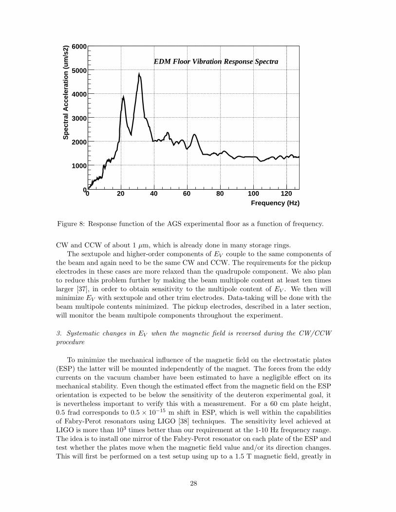
Frequency (Hz)0 20 40 60 80 100 120
Sp
ectr
al A
ccel
erat
ion
(u
m/s
2)
0
1000
2000
3000
4000
5000
6000
EDM Floor Vibration Response Spectra
Figure 8: Response function of the AGS experimental floor as a function of frequency.
CW and CCW of about 1 μm, which is already done in many storage rings.The sextupole and higher-order components of EV couple to the same components of
the beam and again need to be the same CW and CCW. The requirements for the pickupelectrodes in these cases are more relaxed than the quadrupole component. We also planto reduce this problem further by making the beam multipole content at least ten timeslarger [37], in order to obtain sensitivity to the multipole content of EV . We then willminimize EV with sextupole and other trim electrodes. Data-taking will be done with thebeam multipole contents minimized. The pickup electrodes, described in a later section,will monitor the beam multipole components throughout the experiment.
3. Systematic changes in EV when the magnetic field is reversed during the CW/CCWprocedure
To minimize the mechanical influence of the magnetic field on the electrostatic plates(ESP) the latter will be mounted independently of the magnet. The forces from the eddycurrents on the vacuum chamber have been estimated to have a negligible effect on itsmechanical stability. Even though the estimated effect from the magnetic field on the ESPorientation is expected to be below the sensitivity of the deuteron experimental goal, itis nevertheless important to verify this with a measurement. For a 60 cm plate height,0.5 frad corresponds to 0.5 × 10⁻¹⁵ m shift in ESP, which is well within the capabilitiesof Fabry-Perot resonators using LIGO [38] techniques. The sensitivity level achieved atLIGO is more than 103 times better than our requirement at the 1-10 Hz frequency range.The idea is to install one mirror of the Fabry-Perot resonator on each plate of the ESP andtest whether the plates move when the magnetic field value and/or its direction changes.This will first be performed on a test setup using up to a 1.5 T magnetic field, greatly in
28

Figure 9: The electric field plates showing the beam locations 40 cm apart verticallytraveling into and out of page. The electric field of one beam influencing the other beamis negligible due to shielding from the plates.
excess of the ≈ 0.5 T field required for the actual experiment with deuterons.Our collaborators from Italy (Legnaro and Trieste) have developed a very sensitive,
high finesse, Fabry-Perot resonator [39] for the needs of the PVLAS experiment usingtechnology similar to LIGO. Their Fabry-Perot resonator, with the addition of a referencelaser cavity, is expected to have the required sensitivity for our needs [40]. We expect thistest to be the first we perform in the early stages of the experimental construction.
Another effect that could be different in going from CW to CCW is the so-called patcheffect or floating charges. The materials in the vicinity of the storage region could chargeup during the deuteron storage time, in which case the electric field would influence thestored beam. In order to avoid such a possibility, the materials would need to be madeof conducting metal and grounded. Even so, a thin oxidized layer on their surface coulddevelop with time. In the Berkeley Tl experiment, the electric field plates were originallymade out of Aluminium [41]. An oxidized aluminum layer developed, which became aproblem because it acted like a high voltage insulator accumulating charge [41]. Thisproblem disappeared when they used Cu plates. The oxidized layer in Cu is conducting.
In our experiment we intend to pay special attention to minimizing the patch effect.Special care will be paid to avoid backstreaming into the vacuum system from the vacuumpumps. Finally, the electrical charges accumulated due to a non-conducting layer will be
29

mostly the same with CW and CCW injection.
4. Imperfect CW/CCW reversal of Magnetic Field
The presence of an EDM will cause the spin to develop a vertical component, i.e.,the total spin precession plane will be out of the horizontal plane. As can be seen fromEq. (16) the influence of the EDM on the spin precession plane will be minimal whenωa is not minimized, while the contrary is true when ωa is minimized. Therefore, theEDM signal is the change of the spin precession plane between the following two runningconditions: (1) the g− 2 precession rate is minimized so that the deuteron spin is allowedto precess by about π rad within the 103 s storage period, and (2) the deuteron spin isallowed to precess 10π rad in a 103 s period. In order to be able to descern the EDMeffect, the B-field direction between the above two conditions cannot be allowed to changemore than that expected from the EDM effect itself.
With a 109 reduction of the g−2 precession, the ωa rate will be of the order of 1 mrad/s,i.e. 1 rad in 103 s. For a 10−29 e ·cm deuteron EDM, the spin precession rate ωedm will beof the order of 10 nrad/s or 10 μrad in 103 s, i.e. the EDM at the 10−29 e ·cm level causesthe spin precession plane to tilt by a little over 10 μrad.
However, the definition of “horizontal” might be subject to detector alignment andacceptance considerations. In order to define this plane uniquely for each polarimeter,we will adjust the magnetic field, B, to cancel the g − 2 precession at the 3× 10⁻⁹ level.This allows the spin to make about five complete turns “horizontally”. The tilt due to theEDM in this case is going to be small, less than 0.1 μrad, as is apparent from Eq. (16).Then to go to the 10−9 cancellation level, we only need to change the amplitude of themagnetic field by about ΔB/B = 3 ppm. We can apply this extra magnetic field in thesame direction as B to much better than 1 mrad, so that the total B-field orientation willchange less than 3 nrad, a much smaller change than the 10 μrad expected from the EDMeffect.
In every CW injection we will have up to three runs, with variable control of the g− 2precession rate, so that at the end of the three 103 s running periods the spin will makeabout 5, 2 and 1/2 horizontal turns, respectively. The differences of the spin precessionplane for those running conditions will be uniquely determined for this CW injection. Atthe end of the above three runs we will go into CCW injection, repeating the same runningpattern. At the end of this operation we will compare the two sets of results. In simpleterms, the sum corresponds to a background effect while the difference corresponds to agenuine EDM signal.
5.2 Polarimeter Systematic Errors
The vector left-right asymmetry that carries the EDM signal will be small in comparisonto a number of other signals recorded by the EDM ring polarimeters. In order to separatethis component from these other asymmetries, including systematic sources of a sin ξterm (ξ = 0 along the momentum direction), the measurement plan requires allowingsome residual anomalous precession (ωa �= 0) and a continuous measurement of the beampolarization during the store. With full azimuthal coverage, the polarimeters will alsomeasure down-up asymmetries, a comparison of left and right with down and up thatis sensitive to t22 polarization, and changes at large scattering angle in the azimuthallyaveraged rate that is sensitive to t20 polarization.
With this information, we can define a set of requirements that must be met by anyreal EDM signal. These include:
30

• the correct phase dependence on ωa.
• no dependence on 2ωa.
• changing sign with the reversal of the vector polarization.
• reversal of the EDM effect when ωa changes sign.
• magnitude of the EDM effect going as 1/ωa.
• EDM effect not depending on location of the polarimeter.
• reversal when the beam direction changes between CW and CCW.
Such requirements provide a way to distinguish any true EDM signal from a numberof other effects that create significant contributions to the left-right asymmetry. In allcases, there are multiple ways that various errors are easily distinguishable because theyfail to meet the requirements listed above. The following errors are addressed:
• Any residual vertical polarization that remains after the preparation of the beamand the filling of the storage ring will remain constant throughout the store, sincesuch polarizations are stable regardless of the sign or size of ωa.
• Tensor polarization in the beam will create a left-right asymmetry whenever thepolarization is not perfectly aligned with either the beam velocity or the magneticfield bending radius. Such asymmetries will oscillate with ωa at double the precessionfrequency and will be independent of the magnitude of ωa or the direction of thebeam.
• Software separation of the vertical and horizontal asymmetries may allow some ofthe g−2 asymmetry to appear in the left-right data, but it will not change sign withthe ωa sign change nor increase in size as ωa get smaller.
• False asymmetries due to improper alignment of the beam in the polarimeter willtrack none of the characteristics of an EDM signal.
• False asymmetries can arise due to saturation of the detector response at high ratesthat are themselves polarization-dependent. Such effects do not change with thesign and magnitude of ωa in the proper way.
• No symmetry prevents the beam from acquiring a t20 polarization as it passesthrough the residual gas in the ring. As the store progresses, this induced po-larization rotates with ωa and generates a left-right asymmetry to the extent thatit resembles a t21 polarization. Such effects again oscillate at double the precessionrate. They are also indifferent to the sign of the beam polarization from the ionsource and do not change sign when the direction of the beam reverses.
If ωa is stable during the store, one analytic approach would be to fit the asymmetriesusing a Fourier series based on ξ = ωat and extract the coefficient of the sin ξ termassociated with an EDM. This coefficient would then have to have the right propertieswhen certain experimental parameters are changed (spin-flip, sign of ωa, beam revolution
direction) as well as varying with ωa as ωedm/√ω2
edm + ω2a.
To summarize how the EDM signal can be separated from other sources of a left-rightasymmetry, the table (4) below lists the 6 causes of an asymmetry given above and testablecharacteristics for each cause. A plus indicates that for this test the asymmetry appears
31
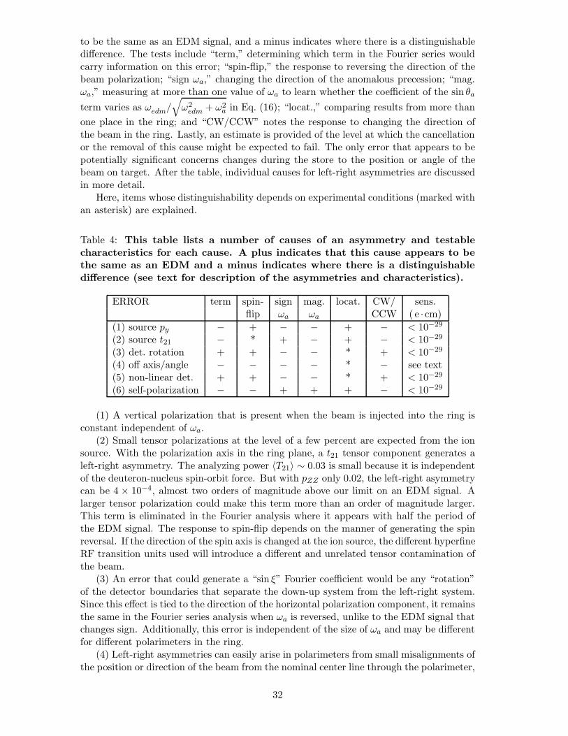
to be the same as an EDM signal, and a minus indicates where there is a distinguishabledifference. The tests include “term,” determining which term in the Fourier series wouldcarry information on this error; “spin-flip,” the response to reversing the direction of thebeam polarization; “sign ωa,” changing the direction of the anomalous precession; “mag.ωa,” measuring at more than one value of ωa to learn whether the coefficient of the sin θa
term varies as ωedm/√ω2
edm + ω2a in Eq. (16); “locat.,” comparing results from more than
one place in the ring; and “CW/CCW” notes the response to changing the direction ofthe beam in the ring. Lastly, an estimate is provided of the level at which the cancellationor the removal of this cause might be expected to fail. The only error that appears to bepotentially significant concerns changes during the store to the position or angle of thebeam on target. After the table, individual causes for left-right asymmetries are discussedin more detail.
Here, items whose distinguishability depends on experimental conditions (marked withan asterisk) are explained.
Table 4: This table lists a number of causes of an asymmetry and testablecharacteristics for each cause. A plus indicates that this cause appears to bethe same as an EDM and a minus indicates where there is a distinguishabledifference (see text for description of the asymmetries and characteristics).
ERROR term spin- sign mag. locat. CW/ sens.flip ωa ωa CCW (e ·cm)
(1) source py − + − − + − < 10−29
(2) source t21 − * + − + − < 10−29
(3) det. rotation + + − − * + < 10−29
(4) off axis/angle − − − − * − see text(5) non-linear det. + + − − * + < 10−29
(6) self-polarization − − + + + − < 10−29
(1) A vertical polarization that is present when the beam is injected into the ring isconstant independent of ωa.
(2) Small tensor polarizations at the level of a few percent are expected from the ionsource. With the polarization axis in the ring plane, a t21 tensor component generates aleft-right asymmetry. The analyzing power 〈T21〉 ∼ 0.03 is small because it is independentof the deuteron-nucleus spin-orbit force. But with pZZ only 0.02, the left-right asymmetrycan be 4 × 10⁻⁴, almost two orders of magnitude above our limit on an EDM signal. Alarger tensor polarization could make this term more than an order of magnitude larger.This term is eliminated in the Fourier analysis where it appears with half the period ofthe EDM signal. The response to spin-flip depends on the manner of generating the spinreversal. If the direction of the spin axis is changed at the ion source, the different hyperfineRF transition units used will introduce a different and unrelated tensor contamination ofthe beam.
(3) An error that could generate a “sin ξ” Fourier coefficient would be any “rotation”of the detector boundaries that separate the down-up system from the left-right system.Since this effect is tied to the direction of the horizontal polarization component, it remainsthe same in the Fourier series analysis when ωa is reversed, unlike to the EDM signal thatchanges sign. Additionally, this error is independent of the size of ωa and may be differentfor different polarimeters in the ring.
(4) Left-right asymmetries can easily arise in polarimeters from small misalignments ofthe position or direction of the beam from the nominal center line through the polarimeter,
32
or from some asymmetry in the efficiency of the detectors on opposite sides, including theirassociated electronics and data acquisition logic. This commonplace error has typicallybeen cancelled for many experiments by flipping the sign of the polarization of the beam,since these asymmetries do not depend on such changes. The analysis can be made morerobust by considering “cross-ratios” that involve both left and right rates and both spinstates [42]. If the left-right asymmetry is small (which it is), then corrections to the cross-ratio that depend on the derivatives of the analyzing power with angle appear at thirdorder because ε becomes a small parameter.
(5) Rates in the detectors are high, and photomultipliers as well as other systemsare well-known to have gains that depend on rate. These effects result in a detectorresponse that, while it may depend linearly on rate over some operating range, is nolonger proportional to rate. The rate in our system is an oscillation (on top of a constantor falling background) that comes from the spin precession. The largest effect is the down-up asymmetry that originates from the radial component of the deuteron spin, even if thedetector is close to the plane of the storage ring. So long as the rate-dependent changesare in a linear range, only the magnitude of the asymmetry is affected. If the responsecontains a quadratic term and is different on the left and right sides, then this feeds intothe sin ξ term in the Fourier analysis. As the stored beam loses intensity, the size of thisterm changes. Its dependence on ωa will distinguish it from an EDM signal.
(6) Self-polarization of the beam is possible [43] since the ratio of the forward-nuclear tothe forward-Coulomb amplitudes may have a significant magnitude when integrated overthe acceptance of the storage ring. This effect has not been observed with corroborationand might appear for the first time in this experiment. Scattering spin-one deuteronsfrom residual gas may introduce a t20 moment that “smears” into a t21 polarization (anda left-right asymmetry) as the spin precesses in-plane. This is the only systematic errorthat gets larger as ωa gets smaller. It is distinguished by its Fourier signature and thefact that it is independent of the beam polarization. An important ancillary signature isa steadily rising t20 and t22 polarization.
All of these systematic effects that appear in the operation of the polarimeter, in-cluding those such as t21 and self-polarization that are unique to spin-one beams, aredistinguishable from an EDM signal in at least two ways. It will be important that theanalysis consider and model any effects that appear in the experiment at a measurablelevel. Otherwise, poor reproduction of the data will generate noise in the coefficient of theEDM term that will limit the sensitivity of the experiment.
5.3 Pickup Electrodes
The beam itself is the optimal tool for understanding the operational characteristics ofthe EDM storage ring, and this tool is made available with a system of Beam PositionMonitors (BPM). A BPM system is an integral part of all storage rings. The BPM systemis primarily used to determine orbit properties, but it can also allow the measurementof the beta-functions, the dispersion and the bunch length. The EDM storage ring willrequire beam position monitors in both the arcs and in the straight sections. The monitorsare needed in the arcs to sense differences in the radial position of the beam for CW andCCW injection. A difference in the radial position between CW and CCW injection leadsto a difference in average velocities, which, in turn, affects the accuracy of the cancellationof the vertical electric field. Since the required cancellation is 0.1 ppm and the bendingradius is about 8.5 m, the relative beam position must be measured to the order of 1 μm.The monitors are needed in the straight sections to sense changes in the beam positionwith respect to the polarimeters. Beam movement with respect to the polarimeter causes afalse asymmetry. Since the expected asymmetry is 5×10⁻⁶, the relative beam position here
33
must also be measured to the order of 1 μm. The number and position of the monitorswill be better understood after measurements of field reversal accuracy on dipole andquadrupole prototypes have been made.
Beam position sensitivities of the order of 1μm have been achieved with pick-up elec-trodes. The typical configuration has two pairs of opposing conducting strips offset by90◦. Each strip subtends the same azimuthal angle. The electric and magnetic fields ofthe circulating beam induce currents in the strips. The strips may be capacitively cou-pled to the beam line, in which case the BPM is an electrostatic device, or the stripsmay form with the beam pipe a transmission line with well-defined impedance. While thefundamental limitation of these devices is the thermal noise power, the low signal levels(typically ∼ 10 μV for ∼ 1 mA of beam) require careful exclusion of the electromagneticinterference that is endemic to the accelerator environment.
6 Cooled deuteron beam
For the present parameters of the EDM ring, it is desirable to have a small horizontal beamsize at the location of the plates. For maximum dispersion Dx = 2.9 m, rms momentumspread of 2.5 × 10⁻⁴, maximum horizontal beta function of βh = 12 m, and emittance of3π mm mrad (95%, normalized), the total 95% beam radius in the horizontal direction is10 mm, which barely fits into the 20 mm space between the plates.
After the EBIS injector upgrade, it is expected to have an rms momentum spread ofthe deuteron bunch of about 2.5 × 10⁻⁴. The expected emittance for 1011 particles perbunch is about 5π mm mrad (95%, normalized). Such expected beam parameters almostsatisfy the requirement for the EDM experiment and correspond to a full horizontal beamsize of 26 mm at the plates.
However, the current momentum spread in the AGS is determined not by the injectorbut rather by the Booster. For example, the current momentum spread in the Tandemis very small (less than 10−4), but in the AGS is about 5 × 10⁻⁴ rms. It seems to bedetermined by the process of adiabatic capture in the Booster. As a result, one mayexpect to have slightly larger values of the rms momentum spread at the AGS injectionof about 5× 10⁻⁴ rms.
If one wants to have a smaller emittance or if the momentum spread at the AGSinjection happen to be bigger than expected, then electron cooling can be used to getsmall momentum spread. For example, with 95% normalized emittance of 1.6π mm mrad(3π mm mrad unnormalized) and an rms momentum spread of 2.4×10⁻⁴, the full horizon-tal beam size in the location of the plates is 15 mm, which fits comfortably in the presentdesign with 20 mm space. Such parameters will require a factor of 3 cooling in transverseemittance and maybe a factor of 2 in longitudinal cooling, based on expected beam param-eters. Such modest cooling is easily achievable with a standard electron cooler. Note thatelectron cooling can provide much stronger cooling (for example, for momentum spread),which maybe needed to obtain a long spin coherence time.
To cool deuterons at the EDM energy requires a low-energy cooler (about 60 keVelectron kinetic energy). Such a cooler is a common device. It can be built on the scale of2-3 years by the Novosibirsk group (BINP). The total cost of such a cooler is about 1MEuros.
If installed in the AGS, the cooler needs to fit into the available space between themagnets. Such a cooling system was considered for the scenario of cooling a coastingbeam, as well as a bunched beam, in the AGS. The required beam parameters were foundto be achievable with cooling. However, cooling in the AGS is limited to just modestcooling due to the space-charge limit.
34
The safest way of getting a small momentum spread and emittance for the experimentis to provide cooling directly in the EDM ring, rather than in the AGS. This removes theproblem of space charge and instabilities in AGS for a cooled beam. It allows one to geta very small emittance and momentum spread at the beginning of the experiment. Thefull space needed for such a cooler is 2.5-3 meters.
Electron coolers at low energies are well established devices which have been built forthe last 30 years [44]. There are presently tens of electron coolers operating around theworld. The most recent were built for 1) IMP (Lanzhou, China); 2) LEIR (CERN); 3)S-LSR (Kyoto, Japan). Coolers for Lanzhou and CERN were built by BINP, Novosibirsk,Russia.
7 DAQ and Electronics
In a precision experiment such as this, high demands are placed on the electronics anddata acquisition. It must be able to handle very large amounts of data, and should notintroduce systematic effects, such as those due to, e.g., variations in the readout rate(deadtime) or other electronics or software related phenomena (buffering). Data flowsfrom several quite different systems (polarimeter, tilt-meters, beam-position monitors,pickup electrodes, Fabry-Perot, PbO) must be dealt with seamlessly for reconstruction ofthe EDM signal. We will evaluate existing and proven data acquisition software, such asthe Midas system (https://midas.psi.ch/), for use in our experiment.
The main source of data will be the polarimeters. Several configurations are beingconsidered. At a minimum, the polarimeter readout system must be able to distinguishfrom which bunch (of the couple circulating in the ring) an event originates, either byimplementing bunch-indexing or by allowing time reconstruction. More sophisticatedcapabilities, such as signal magnitude reconstruction (e.g. for particle identification) orvertex reconstruction require additional functionality.
Typically, polarimeter readout is based on recording the number of hits in each of itssegments during several ms or longer. To track individual bunches circulating in the ring,a set of several scaler modules, each with a gate synchronized with the passage of a singlebunch, would be sufficient. With Struck Innovative Systems (http://www.struck.de/),implementation of this functionality in their SIS3820 multi-purpose scaler has been stud-ied. It is expected that up to 40 individual 32-channel scalers with up to 50 MHz cyclingcan be implemented. For our application, this might be sufficient, resulting in a robust,extremely compact and undemanding setup.
The polarimeter will detect several percent of the of deuterons extracted from thering. Over the course of a fill, this will amount to 109−10 events, or 106−7 events persecond. Readout of such an event rate using multi-hit time-to-digital converters (MTDCs)can be accomplished with presently available electronics, e.g., the CAEN V1290 MTDC.The corresponding data volume will amount to 4 – 40 MB/s, well within network or diskthroughput limits. A DAQ system based on this scheme is being prepared for use duringthe upcoming experiments at COSY-Julich, where its performance and suitability forpolarimetery will be tested. At the same time, the KVI-developed DAQ software packageCaddie will be tested.
If, besides the arrival time, the magnitude of the signal also needs to be measured,readout using sampling ADCs (waveform digitizers, WFDs) is the best choice. At a typicalevent size of 100 bytes per event, the primary data stream will increase significantly (0.1–1 GB/s). On-line pulse-shape analysis using FPGAs (field-programmable gate arrays)built into the WFD modules, or via in-crate analysis computers is expected to reduce thestored data volume to about twice the data volume of the MTDC-only scheme.
35
A polarimeter based on the micro-megas-TPC or MRPC allows particle identification,and in the case of the TPC also reconstruction of the scattering vertex. Both systemsconsist of a detector placed close to the scattering target, resulting in increased rates.These systems place correspondingly heavy demands on the readout system.
Here we state the case for the micro-megas, but a similar system would be required forthe MRPC. The maximum rate expected in the micro-megas-TPC detector is 5 × 10⁷/s.For 10 cm drift space, a track requires about 2.3μs to reach the readout plane. Thus,a maximum of 92 tracks at all times should be able to be handled by the system. Thereadout electronics could be similar to the T2K electronics for their micro-megas-TPC.It consists of preamplifiers and 40 MHz WFDs to sample the pad signals. Our designrequires 3284 to 4612 readout channels. The cost per electronics channel is of the order of10 Euros. The total cost of these will be about 46 kEuros. A rough estimate of the cost ofthe data acquisition and triggering system is about 50 kEuros. Thus the electronics andreadout system cost is estimated to be 100 kEuros for the micro-megas-TPC.
8 Cost and Schedule
After the proposal is approved, we expect to complete a Technical Design Report (TDR)in roughly six months. After a successful review of the TDR, we will work on the proofof principle of the Fabry-Perot resonator to achieve the required level of accuracy. Inparallel, we will develop the design of the E-field plates and demonstrate the proof ofprinciple by operating them at full voltage in the required magnetic field. With theFabry-Perot resonator, we will have to show that reversing the B-field does not influencemechanically the E-field plates at the required level.
At the same time, we will further develop spin and particle tracking programs to guidethe design of the deuteron EDM storage ring. We expect to be ready to start the ringconstruction three years after the approval of the proposal. The ring construction will taketwo years to complete, at which point we will be ready to take beam. In the first year,we will have an engineering run to shim the B and E-fields and to achieve the requireddeuteron spin coherence time. During the second year, we will be ready for a physics run.We thus expect to have taken the required data by the end of 2013.
36
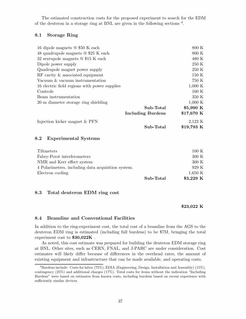
The estimated construction costs for the proposed experiment to search for the EDMof the deuteron in a storage ring at BNL are given in the following sections 4.
8.1 Storage Ring
16 dipole magnets @ $50 K each 800 K48 quadrupole magnets @ $25 K each 800 K32 sextupole magnets @ $15 K each 480 KDipole power supply 250 KQuadrupole magnet power supply 250 KRF cavity & associated equipment 150 KVacuum & vacuum instrumentation 750 K16 electric field regions with power supplies 1,000 KControls 160 KBeam instrumentation 350 K20 m diameter storage ring shielding 1,000 K
Sub-Total $5,990 KIncluding Burdens $17,670 K
Injection kicker magnet & PFN 2,123 KSub-Total $19,793 K
8.2 Experimental Systems
Tiltmeters 100 KFabry-Perot interferometers 300 KNMR and Kerr effect system 300 K4 Polarimeters, including data acquisition system. 929 KElectron cooling 1,650 K
Sub-Total $3,229 K
8.3 Total deuteron EDM ring cost
$23,022 K
8.4 Beamline and Conventional Facilities
In addition to the ring-experiment cost, the total cost of a beamline from the AGS to thedeuteron EDM ring is estimated (including full burdens) to be $7M, bringing the totalexperiment cost to $30,022K .
As noted, this cost estimate was prepared for building the deuteron EDM storage ringat BNL. Other sites, such as CERN, FNAL, and J-PARC are under consideration. Costestimates will likely differ because of differences in the overhead rates, the amount ofexisting equipment and infrastructure that can be made available, and operating costs.
4Burdens include: Costs for labor (75%), EDIA (Engineering, Design, Installation and Assembly) (15%),contingency (25%) and additional charges (17%). Total costs for items without the indication “IncludingBurdens” were based on estimates from known costs, including burdens based on recent experience withsufficiently similar devices.
37
9 Conclusion
We propose a search for a deuteron EDM at the 10−29 e · cm level. At this level, we willbe sensitive to a non-zero deuteron EDM value predicted by a number of theories beyondthe SM. The strength of the proposed method resides in the following features:
• The g − 2 precession can be reduced to the required 10−9 level.
• Our storage ring design makes possible spin coherence times greater than 103 s.
• High intensity (4 × 10¹¹ per cycle), highly polarized deuteron beams are readilyavailable.
• Polarimeters with high analyzing power (0.5) are available in the energy range ofinterest.
• Potential systematic errors can be corrected by polarization measurements of counter-rotating stored beams and polarization reversals.
The successful conclusion of this experiment will constitute a major advancement inthe quest for a non-zero EDM of a fundamental particle.
We are greatly indebted to Sidney Orlov for improving the style and readability of thisproposal.
References
[1] J.H. Smith, E.M. Purcel, and N.F. Ramsey, Phys. Rev. 108, 120 (1957).
[2] F.J.M. Farley et al., Phys. Rev. Lett. 93, 052001 (2004); hep-ex/0307006.
[3] Y.F. Orlov et al., Phys. Rev. Lett. 96, 214802 (2006); hep-ex/0605022.
[4] The application of spin dressing to the EDM search was independently suggestedby D. Beck and D. Kawall. A semi-realistic case was studied and showed that themethod is very promissing but many years away from complete development. Y.K.Semertzidis, EDM internal report on spin re-winding, 2007.
[5] “Deuteron EDM Proposal: Search for a Permanent Deuteron Electric Dipole Momentat the 10−27 e·cm Level”, M. Aoki et al., proposal to the BNL AGS, September 2004.The document is available from our official web site: “http://www.bnl.gov/edm/”.
[6] R. Gupta, et al., “React & Wind Nb3Sn Common Coil Dipole”, Presented at ASC2006, IEEE Trans. on Appl. Supercond., Vol. 17, No. 2, pp. 11301135 (2007); R.C.Gupta, “A Common Coil Design for High Field 2-in-1 Accelerator Magnets”, ParticleAccelerator Conference, pp 3345-3347 (1997).
[7] V.S. Kashikhin, et al., “Development and Test of Single-Layer Common Coil DipoleWound with Reacted Nb3Sn Cable”, IEEE Trans. on Appl. Supercond., Vol. 14, Issue2, pp. 353356 (2004).
[8] L. Chiesa, et al., “Magnetic Field Measurements of the Nb3Sn Common Coil DipoleRD3c”, Particle Accelerator Conference, pp 170-172 (2003).
[9] Normal conducting RF-cavities achieve much higher electric fields when their surfacesare treated with high pressure water rinsing (HPR). The same is true for Ti surfacesused as photocathodes in electron machines: B.M. Dunham et al., Proceed. of PAC07,1224 (2007), Albuquerque, New Mexico, USA.
38
[10] Lawrence Cranberg, Journal of Applied Physics 23, 518 (1952).
[11] O. Prokopiev presentations on the FNAL electrostatic separators conditioning,available fromhttp://beamdocs.fnal.gov/DocDB/0023/002358/001/separator20−hand−polish−jul21−2006.ppt,http://www-btev.fnal.gov/DocDB/0029/002944/001/BTeV−EBS−Polsw−Pwrsup.ppt, andhttp://www.cap.bnl.gov/mumu/conf/collider-071203/talks/RJohnson2-071203.pdf.
[12] A. V. Akindinov, et al., Nucl. Instr. & Methods A 532, 611 (2004)
[13] The micro-megas detector, first published in I. Giomataris et al., NIM 376 (1996)29; it can work at very high rates since space charge effects are suppressed and hasbeen used on COMPASS and NA48 experiments at CERN. The mm-TPC version isbeing developed for the T2K experiment in Japan and for the ATLAS inner trackerbeing developed at BNL.
[14] C.A. Baker et al., Phys. Rev. Lett. 97, 131801 (2006).
[15] B.C. Regan et al., Phys. Rev. Lett. 88, 071805 (2002).
[16] A.D. Sakharov, JETP Lett., 5, 24 (1967).
[17] M.V. Romalis et al., Phys. Rev. Lett. 86, 2505 (2001).
[18] V.F. Dmitriev and R.A. Sen’kov, Phys. Rev. Lett. 91, 212303 (2003).
[19] C.P. Liu and R.G.E. Timmermans, Phys. Rev. C 70, 055501 (2004).
[20] I.B. Khriplovich, R.A. Korkin, Nucl. Phys. A 665, 365 (2000), nucl-th/9904081.
[21] O. Lebedev et al., Phys. Rev. D 70, 016003 (2004).
[22] M. Pospelov and A. Ritz, Ann. Phys. 318, 119 (2005), hep-ph/0504231.
[23] R.L. Garwin and L. Lederman, Nuovo Cimento 11, 776 (1959).
[24] J. Bailey et al., J. Phys. G4, 345 (1978).
[25] D.F. Nelson, A.A. Schupp, R.W. Pidd, and H.R. Crane, Phys. Rev. Lett. 2, 492(1959).
[26] N.F. Ramsey, Annu. Rev. Nucl. Part. Sci. 1990. 40:1-14.
[27] J.D. Jackson, Classical Electrodynamics John Wiley and Sons, Inc., 1974.
[28] A. Silenko et al., January 9, 2003. It can be found at“http://www-ps.kek.jp/jhf-np/LOIlist/pdf/L22.pdf” and from our own web site“http://www.bnl.gov/edm/”. J-PARC: Japan Proton Accelerator Research Complex,“http://j-parc.jp”.
[29] Y. Satou et al., Phys. Lett. B 549, 307 (2002).
[30] V.P. Ladygin et al., Nucl. Instrum. Mathods A 404, 129 (1998).
[31] B. Bonin et al., Nucl. Instrum. Methods A 288, 389 (1990).
[32] B. von Przewoski et al., Phys. Rev. E 68, 046501 (2003).
[33] See T.M. Ito et al., Phys. Rev. Lett. 92, 102003 (2004) and references therein; alsoK.A. Anoil et al., Phys. Rev. Lett. 82, 1096 (1999).
[34] I.B. Vasserman et al., Phys. Lett. B 198, 302 (1987).
[35] A.P. Lysenko, A.A. Polunin, and Yu.M. Shatunov, Particle Accelerators 18, 215(1986).
39
[36] OPERA, Electromagnetic Fields Analysis Program, Vector Fields Ltd., 24 Bankside,Oxford OX5 1JE, England.
[37] T. Roser, private communication.
[38] http : //www.ligo.caltech.edu/
[39] A.M. De Riva, et al., Rev Sci. Instrum. 67, 2680 (1996) “Very high Q frequency-locked Fabry-Perot cavity”. The actual length of the Fabry-Perot resonator used inthe PVLAS experiment is 6.4m long, while the length of a test resonator they usedwas 1.7m long.
[40] G. Cantatore, private communication.
[41] E. Commins, private communication.
[42] G.G. Ohlsen and P.W. Keaton, Jr., Nucl. Instrum. Methods 109, 41 (1973).
[43] V.G. Baryshevski, LANL/Cornell archive hep-ph/0109099; hep-ph/0201202.
[44] I. Meshkov, Proceedings of EPAC 2004, Lucerne, Switzerland.
40