Embed Size (px)
Citation preview

This document is for informational purposes only and is not a legally binding agreement or offer. Trimble makes no warranties and assumes no obligations or liabilities hereunder.
Trimble Navigation Limited, Agriculture Division, 10355 Westmoor Drive, Suite #100, Westminster, CO 80021, USA
© 2007, Trimble Navigation Limited. All rights reserved. Trimble, the Globe & Triangle logo, and AgGPS are trademarks of Trimble Navigation Limited, registered in the United States and in other countries. CMR+, SiteNet, TRIMTALK, and Zephyr Geodetic are trademarks of Trimble Navigation Limited. All other trademarks are the property of their respective owners.
6 August 2007
AgGPS RTK 450 MHz Mobile Base Station and Rover Unit: Setting Up This Support Note describes how to set up a Trimble® AgGPS® RTK 450 mobile base station and rover radio. Instructions apply to base station and rover combinations with the following components:
Item Components Base station AgGPS RTK Base 450 Receiver
Zephyr Geodetic™ Model 2 antenna
Rover AgGPS 252 GPS receiver AgGPS 450 radio
To configure the base station and rover, complete the following steps:
Step 1. Set up the hardware.
Step 2. Start the Base Station.
Step 3. Check the base station configuration.
Step 4. Check the firmware version.
Step 5. Upload a new firmware.
Step 6. Check and update.
Step 7. Check the rover radio setup.
Step 8. Check the corrections.
Step 9. Set up the receiver to use RTK corrections.
Note: To connect the AgGPS 450 rover radio to the serial port of your computer, you require a null modem configuration cable. For instructions on creating the cable, refer to the AgGPS 450 Radio: Configuration Support Note.
http://agpartners.trimble.com Page 1

Step 1. Setting up the hardware Note: Make sure that you set up the base station in an open area where there is a clear view of the sky in all directions.
Quick setup: Short range radio Use this setup for a short radio range, using the internal battery.
1. Attach the elevating base to the tripod:
2. Mount the GNSS antenna and then connect it to the receiver:
http://agpartners.trimble.com Page 2

3. Connect the rubber antenna straight into the radio port:
4. If required, connect the external battery cable:
http://agpartners.trimble.com Page 3

Medium range radio Use this setup when using the radio remote antenna, and an internal battery.
1. Attach the remote radio antenna bracket and the elevating base to the tripod:
2. Mount both the GNSS antenna and the radio antenna and then connect them to the receiver:
http://agpartners.trimble.com Page 4
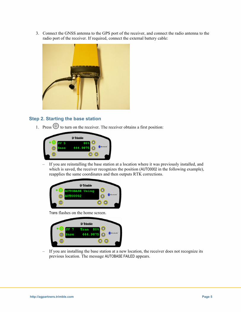
3. Connect the GNSS antenna to the GPS port of the receiver, and connect the radio antenna to the radio port of the receiver. If required, connect the external battery cable:
Step 2. Starting the base station
1. Press E to turn on the receiver. The receiver obtains a first position:
– If you are reinstalling the base station at a location where it was previously installed, and
which is saved, the receiver recognizes the position (AUTO0002 in the following example), reapplies the same coordinates and then outputs RTK corrections.
Trans flashes on the home screen.
– If you are installing the base station at a new location, the receiver does not recognize its
previous location. The message AUTOBASE FAILED appears.
http://agpartners.trimble.com Page 5

2. From the Home screen, press L three times:
3. In the Base Station screen, press G to activate the Edit mode. Edit Current flashes.
4. Press K . New Base (Here) flashes:
5. Press L to set up the base station at this new position.
6. Press L again:
In the Base Name screen, you are prompted, by default, to accept CREF0001.
7. Do one of the following:
– If you have already saved a position named CREF0001, and you now press L , you overwrite CREF0001 and save the new coordinates under this name. This means that you lose the base station location corresponding to the old CREF0001.
– If you want to keep the previous position (CREF0001) for future use, save the new position under a new name, for example, CREF0002. To do this:
a. Press G to activate the Edit mode and to move the cursor to the next character.
b. Press K or J to change the value of the character.
c. Press L to accept the changes.
http://agpartners.trimble.com Page 6

8. In the Base Code screen that appears, you can enter a description of the base station position—up to 16 characters:
9. Press L several times until the home screen appears.
The Base Station now transmits RTK corrections:
Step 3. Checking the base station configuration In this step, you make sure that the base station is correctly configured.
1. From the home screen, press L several times to access the Antenna Type screen.
The RTK base station uses the Zephyr Geodetic Model 2 GNSS antenna. Make sure that Zephyr Geo Mdl 2 is selected. To change the setting:
a. Press G to activate the Edit mode.
b. Press K or J to change the value.
c. Press L to accept the changes.
http://agpartners.trimble.com Page 7

2. Press L again to access the Port and correction Format screen.
Make sure that the Radio port is set to output RTK CMR+™ corrections:
If it is not, set the output format of both the Lemo and the Modem ports to None, and set the output format of the Radio port to RTK CMR+ :
http://agpartners.trimble.com Page 8

To do this:
a. Press K or J to select the Port or the Format field.
b. Press G to activate the Edit mode.
c. Press K or J to change the value.
d. Press L to accept the changes.
e. Press L again to access the Radio Frequency screen.
Confirm that the correct frequency is selected:
If you want to select another frequency from the built-in radio, press G to activate the Edit mode, press K or J to scroll through and then select from the available frequencies. Press L to accept the changes.
3. Check the receiver port settings:
Press L to access the NMEA and GSOF settings. Make sure that they are all set to Off:
http://agpartners.trimble.com Page 9

Step 4. Checking the firmware version
• From the home screen, press J twice to access the Firmware status screen.
The firmware should be version 3.32 or later:
Step 5. Uploading new firmware 1. Connect the receiver to the computer serial port using the DB26 adaptor P/N 57168 (1), the Null
Modem cable P/N 18532 (2), and the power supply (3), as shown below.
Note: Trimble recommends that you use an external power supply to run the receiver while upgrading the firmware.
1
2
3
http://agpartners.trimble.com Page 10

2. Install and run the WinFlash utility. If required, you can download this from the Agriculture Partners website at http://agpartners.trimble.com/. Select Products A–Z > AgGPS RTK Base 900/450 Receiver > Technical Support > AgGPS RTK 450/900 Base Downloads > AgGPS RTK Base 450/900 Firmware - v3.32.
3. From the Device type list, select Trimble AgGPS Receiver and then click Next:
http://agpartners.trimble.com Page 11

4. From the Operations list, select Load GPS software and then click Next:
5. From the Available Software list, select the correct software to upload to the receiver and then click Next:
http://agpartners.trimble.com Page 12

6. Review the settings and then click Finish:
The utility connects to the receiver and performs the firmware upgrade.
Step 6. Checking and updating In this step, you check the radio settings, update the radio frequencies, check the radio information, and update the receiver options.
Checking the radio setting 1. Return to the WinFlash Operation Selection screen:
http://agpartners.trimble.com Page 13

2. From the Operations list, select Configure Radio Settings and then click Next:
3. Click Finish. The utility connects to the radio:
Make sure that the settings are as follows:
Option Setting Mode Base (Transmit) Channel sharing Off
Note: Station ID is a Federal Communications Commission requirement for US licensed users; it is not used in the EU.
http://agpartners.trimble.com Page 14

Make sure that the base station is configured as follows:
If you select this channel spacing Use this wireless mode (protocol) 12.5 KHz TRIMTALK™ 450S at 4800 bps 25 KHz TRIMTALK 450S at 9600 bps
4. Click OK. The utility connects to the radio and applies the new settings.
Updating the radio frequencies 1. Return to the WinFlash Transceiver Configuration screen:
2. Click Update Freq:
http://agpartners.trimble.com Page 15

3. Browse your computer and then select the Frequencies Update file to load:
4. Click OK. The utility uploads the Frequencies Update file to the radio.
Checking the radio information 1. Return to the WinFlash Transceiver Configuration screen:
2. Click Radio Info. Check that the correct channel spacing is being set into the radio.
Note: To change the channel spacing, you must upload a new Frequencies Update file that includes the required channel spacing.
http://agpartners.trimble.com Page 16

Updating the receiver options 1. Return to the WinFlash Operation Selection screen:
2. Select Update receiver options and then click Next:
3. Enter the Password for the option that you want to enable (for example, UHF 2 Watts) and then click Next.
Step 7. Checking the rover radio setup In this step, you make sure that the AgGPS rover radio is set up correctly.
1. Use the null modem cable to connect the AgGPS 450 rover radio to your computer. For instructions on creating the cable, refer to the AgGPS 450 Radio: Configuration Support Note.
2. Open the rover radio Configuration screen.
http://agpartners.trimble.com Page 17

a. Install the WinFlash utility. If required, you can download this from the Trimble website (http://www.trimble.com) under the SiteNet 450 product category.
Note: All WinFlash utility modules that you load onto your computer must be installed at the same location under the same WinFlash directory, for example, C:\Program Files\Trimble\WinFlash.
b. Run the WinFlash utility:
c. From the Device type list, select SiteNet 450 Transceiver (v1.20) and then click Next:
http://agpartners.trimble.com Page 18

d. From the Operations list, select Configure SiteNet 450 and then click Next:
e. Click Finish. The utility connects to the radio:
http://agpartners.trimble.com Page 19

The rover radio Configuration screen appears:
f. Check that the Data Port group settings are as follows:
Data Port category Setting Baud Rate 38400 Parity None
g. Check that the rover radio is set as follows:
If the channel spacing is … Use this wireless mode (protocol) … 12.5 kHz SiteNet 450 at the base station TRIMTALK 450S at 4800 bps 25 kHz SiteNet 450 at the base station TRIMTALK 450S at 9600 bps
h. If you make any changes, click Set to save them the radio.
http://agpartners.trimble.com Page 20

3. Check that the AgGPS 450 radio has the latest firmware:
a. From the rover radio Configuration screen, click Radio Info:
b. Click Save to File and then save the file to your computer.
c. In the saved file, make sure that the Product Family is AgGPS450 and that the Firmware Version is 1.30 or later, as shown below:
Radio Configuration - Fri Jul 07 13:35:23 2006 ------------------------------------------------------ Product Family: AgGPS450 Port Settings: 38400,8 Data,1 Stop,No Parity Firmware Version: 1.30 Hardware Version: 1.00 (dated 08/01/04) Serial Number: 4541160854 Location Code: 1 ----------------------------------------------
http://agpartners.trimble.com Page 21

Step 8. Checking the corrections In this step, you make sure that the rover radio is receiving corrections from the base station.
A single LED on the back of the AgGPS 450 radio indicates the operating state of the radio. When you turn on the radio, the LED emits a solid light, which may be orange, or green and orange. You should be able to see a solid orange and a solid green light.
LED state Solid orange only: The radio is not receiving corrections.
Solid orange and solid green: The radio is receiving corrections.
1. Check that the radio is receiving CMR messages:
a. Connect the AgGPS 450 radio to the computer.
b. Download and install the WinTXRX software.
http://agpartners.trimble.com Page 22
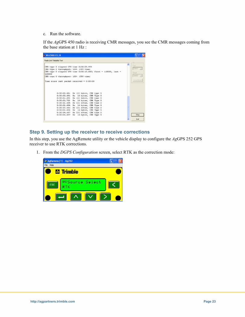
c. Run the software.
If the AgGPS 450 radio is receiving CMR messages, you see the CMR messages coming from the base station at 1 Hz :
Step 9. Setting up the receiver to receive corrections In this step, you use the AgRemote utility or the vehicle display to configure the AgGPS 252 GPS receiver to use RTK corrections.
1. From the DGPS Configuration screen, select RTK as the correction mode:
http://agpartners.trimble.com Page 23

2. Set Port B to RTK Link:
a. From the home screen, press 3 twice. The Configuration screen appears.
b. Press 2. The GPS Config screen appears.
c. Press 3 until the Port B Config screen appears:
d. Set Port B to RTK Link:
3. From the RTK Config screen, check that the RTK Base Station ID is set to 255:
a. From the home screen, press 3 twice. The Configuration screen appears.
b. Press 2. The GPS Config screen appears.
c. Press 3 twice. The RTK Config screen appears.
http://agpartners.trimble.com Page 24

d. Press 2. The RTKBaseStn ID screen appears:
e. If required, change the ID to 255.
4. Return to the home screen. It shows:
– the percentage of RTK packets entering the receiver (below 99%)
– the age of the correction (below 1 second)
http://agpartners.trimble.com Page 25