Embed Size (px)
Citation preview

Agilent SPS 3 Autosampler
User’s Guide

2 Agilent SPS 3 Autosampler User’s Guide
Notices © Agilent Technologies, Inc. 2003, 2006, 2009-2012, 2014
No part of this manual may be reproduced in any form or by any means (including electronic storage and retrieval or translation into a foreign language) without prior agreement and written consent from Agilent Technologies, Inc. as governed by United States and international copyright laws.
Manual Part Number 8510207700
Edition Eigth edition, September 2014
Agilent Technologies Australia (M) Pty Ltd.
679 Springvale Rd,
Mulgrave, Victoria, 3170, Australia
Warranty The material contained in this document is provided “as is,” and is subject to being changed, without notice, in future editions. Further, to the maximum extent permitted by applicable law, Agilent disclaims all warranties, either express or implied, with regard to this manual and any information contained herein, including but not limited to the implied warranties of merchantability and fitness for a particular purpose. Agilent shall not be liable for errors or for incidental or consequential damages in connection with the furnishing, use, or performance of this document or of any information contained herein. Should Agilent and the user have a separate written agreement with warranty terms covering the material in this document that conflict with these terms, the warranty terms in the separate agreement shall control.
Technology Licenses The hardware and/or software described in this document are furnished under a license and may be used or copied only in accordance with the terms of such license.
Restricted Rights Legend If software is for use in the performance of a U.S. Government prime contract or subcontract, Software is delivered and licensed as “Commercial computer software” as defined in DFAR 252.227-7014 (June 1995), or as a “commercial item” as defined in FAR 2.101(a) or as “Restricted computer software” as defined in FAR 52.227-19 (June 1987) or any equivalent agency regulation or
contract clause. Use, duplication or disclosure of Software is subject to Agilent Technologies’ standard commercial license terms, and non-DOD Departments and Agencies of the U.S. Government will receive no greater than Restricted Rights as defined in FAR 52.227-19(c)(1-2) (June 1987). U.S. Government users will receive no greater than Limited Rights as defined in FAR 52.227-14 (June 1987) or DFAR 252.227-7015 (b)(2) (November 1995), as applicable in any technical data.
Safety Notices
A CAUTION notice denotes a hazard. It calls attention to an operating procedure, practice, or the like that, if not correctly performed or adhered to, could result in damage to the product or loss of important data. Do not proceed beyond a CAUTION notice until the indicated conditions are fully understood and met.
A WARNING notice denotes a hazard. It calls attention to an operating procedure, practice, or the like that, if not correctly performed or adhered to, could result in personal injury or death. Do not proceed beyond a WARNING notice until the indicated conditions are fully understood and met.
WARNING
CAUTION

Contents
Agilent SPS 3 Autosampler User’s Guide 3
Contents
1. Safety Practices and Hazards 7
Electrical Hazards 7
Flammable Liquids 8
Other Precautions 9
Warning Symbols 9
Information Symbols 10
Color Coding 11
CE Compliance 11
Electromagnetic compatibility 11 EN55011/CISPR11 11 ICES/NMB-001 12
2. Introduction 13
Intended Use 14
Specifications 14 Environmental 14 Power 15 Electrical Connections 16 Weights and Dimensions 17
3. Installation 19
Installation Procedure 20
Orientation 21

Contents
4 Agilent SPS 3 Autosampler User’s Guide
Inspection and Unpacking 21 External Damage Check 21 Unpacking 22
Fitting the Spill Tray 25
Installing the Rack Location Mat 26
Installing the Rinse Reservoir 27
Fitting the Pump Tubing 28
Assembling and Positioning the Sample Racks 30 Assembling the Sample Racks 30 Rack Positioning 31
Mounting the Standards Rack(s) 32 Standards Rack Locating Pins 32 Standards Rack 33
Fitting the Sample Probe 34
Connecting the Power 38 Power Connection 39 Instrument Communication Port 41 I/O Port 41 Auxiliary Communications Port 42
4. Operation 43
Startup 43
Software Control 44 Agilent Cary WinUV Software 44
5. Maintenance 45
Routine Maintenance 45

Contents
Agilent SPS 3 Autosampler User’s Guide 5
Cleaning 46
Service 47
Checking the Fuses 47
Spare Parts 49
6. Troubleshooting 51
Reset Procedure 52
Initialization Sequence 52
Communications 52 Operating State Check 54 Error Indicator Codes 55 Probe Arm Jam 55 Failure to Initialize 57 Power Supply Issues 58
7. Diluter 61
Introduction 61
Specifications 63 Dilution Performance 63 Environmental 63 Weights and Dimensions 64
Connections 64
Theory of Operation 66

Contents
6 Agilent SPS 3 Autosampler User’s Guide
This page is intentionally left blank.

Safety Practices and Hazards
Agilent SPS 3 Autosampler User’s Guide 7
1. Safety Practices and Hazards Electrical Hazards 7 Flammable Liquids 8 Other Precautions 9 Warning Symbols 9 Information Symbols 10 Color Coding 11 CE Compliance 11 Electromagnetic compatibility 11
Your Agilent SPS 3 autosampler has been carefully designed so that when used properly you have an accurate, fast, flexible and safe analytical system.
If the equipment is used in a manner not specified by the manufacturer, the protection provided by the equipment may be impaired.
Information about safety practices appears throughout the documentation provided with your accessory. Before using the accessory, you must thoroughly read these safety practices.
Observe all relevant safety practices at all times.
Electrical Hazards The Agilent SPS 3 contains electrical circuits, devices, and components operating at dangerous voltages. Contact with these circuits, devices and components can cause death, serious injury, or painful electrical shock.

Safety Practices and Hazards
8 Agilent SPS 3 Autosampler User’s Guide
Only Agilent-trained, Agilent-qualified, or Agilent-approved customer support representatives may open panels or covers that are retained by screws. Removal of such panels or covers can expose parts that involve the risk of electric shock or personal injury.
Good grounding is essential to avoid a potentially serious electric shock hazard. Ensure that there is an integral ground connection between the metal base of the SPS 3 and the three pin, earth-grounded receptacle.
NOTE The above model is Equipment Class I.
Application of the wrong supply voltage can create a fire hazard and a potentially serious shock hazard, and can seriously damage the SPS 3.
Do not connect the Agilent SPS 3 to the mains power supply until all checks and settings have been completed.
Replace blown fuses with fuses of the size and rating as described in the text adjacent to the fuse holder or in the ‘Fuses’ section on Page 16.
Replace or repair faulty or frayed insulation on power cords.
Flammable Liquids Please observe the following precautions when using your Agilent SPS 3 in conjunction with flammable liquids.
To reduce the risk of fire:
Use only flammable liquids with a flash point of greater than 25 °C above ambient temperature.
Do not allow flammable liquids to come near to any part of the Agilent SPS 3 that consumes power, produces heat, or conducts heat from other areas.
Keep anything capable of igniting a flammable liquid well away from the Agilent SPS 3.

Safety Practices and Hazards
Agilent SPS 3 Autosampler User’s Guide 9
Other Precautions Use of the Agilent SPS 3 in any manner other than that specified by Agilent may impair the protection provided by the equipment.
Use of the Agilent SPS 3 may involve materials, solvents and solutions that are flammable, corrosive, toxic or otherwise hazardous.
Careless, improper, or unskilled use of materials, solvents and solutions can create explosions, fire, toxicity and other hazards that can result in death, serious personal injury and damage to equipment and property.
Always ensure that laboratory safety practices governing the use, handling and disposal of such materials are strictly observed. These safety practices should include the wearing of appropriate safety clothing and safety glasses.
Components of the Agilent SPS 3 move automatically and at speed. Keep clear of the probe arm assembly during operation to prevent injury.
NOTE A protective cover is available to prevent accidental contact with the probe arm assembly. Contact your local Agilent representative for further information.
Warning Symbols The following is a list of symbols that appear in conjunction with warnings in this manual or on the accessory. The hazard they describe is also shown.
The beginning of the warning text is noted by a warning icon:
WARNING

Safety Practices and Hazards
10 Agilent SPS 3 Autosampler User’s Guide
A triangular symbol indicates the warning type. The meanings of the symbols that may appear alongside warnings in the documentation or on the instrument itself are as follows:
Corrosive liquid
Electrical shock
Eye hazard
Fire hazard
Heavy weight
(danger to feet)
Heavy weight
(danger to hands)
Moving parts
Sharp objects
The following symbol may be used on warning labels attached to the Agilent SPS 3. When you see this symbol, refer to the relevant operation or service manual for the correct procedure referred to by that warning label.
Information Symbols The following symbols appear on the instrument for your information.
I Mains power on
0 Mains power off
Fuse
Single phase alternating current
AC supply

Safety Practices and Hazards
Agilent SPS 3 Autosampler User’s Guide 11
Color Coding The various indicator lights appearing on Agilent instruments and associated accessories are color coded to represent the status of the instrument or accessory.
A green light indicates the instrument is in normal/standby mode.
An orange light indicates that a potential hazard is present.
A blue light indicates that operator intervention is required.
A red light warns of danger or an emergency.
CE Compliance Your Agilent SPS 3 autosampler has been designed to comply with the requirements of the Electromagnetic Compatibility (EMC) Directive and the Low Voltage (electrical safety) Directive (commonly referred to as the LVD) of the European Union. Agilent has confirmed that each product complies with the relevant Directives by testing a prototype against the prescribed EN (European Norm) standards.
Proof that a product complies with these directives is indicated by the CE Marking appearing on the rear of the product, and the documentation that accompanies the product containing a copy of the Declaration of Conformity. The Declaration of Conformity (DoC) is the legal declaration by Agilent that the product complies with the directives listed above, and shows the EN standards to which the product was tested to demonstrate compliance.
Electromagnetic compatibility
EN55011/CISPR11 Group 1 ISM equipment: group 1 contains all ISM equipment in whichthere is intentionally generated and/or used conductively coupled radio- frequency energy which is necessary for the internal functioning of the equipment itself.

Safety Practices and Hazards
12 Agilent SPS 3 Autosampler User’s Guide
Class A equipment is equipment suitable for use in all establishments other than domestic and those directly connected to a low voltage power supply network which supplies buildings used for domestic purposes.
This device complies with the requirements of CISPR11, Group 1, Class A as radiation professional equipment. Therefore, there may be potential difficulties in ensuring electromagnetic compatibility in other environments, due to conducted as well as radiated disturbances.
Operation is subject to the following two conditions:
1 This device may not cause harmful interference.
2 This device must accept any interference received, including interference that may cause undesired operation.
If this equipment does cause harmful interference to radio or television reception, which can be determined by turning the equipment off and on, the user is encouraged to try one or more of the following measures:
1 Relocate the radio or antenna.
2 Move the device away from the radio or television.
3 Plug the device into a different electrical outlet, so that the device and the radio or television are on separate electrical circuits.
4 Make sure that all peripheral devices are also certified.
5 Make sure that appropriate cables are used to connect the device to peripheral equipment.
6 Consult your equipment dealer, Agilent Technologies, or an experienced technician for assistance.
Changes or modifications not expressly approved by Agilent Technologies could void the user’s authority to operate the equipment.
ICES/NMB-001 This ISM device complies with Canadian ICES- 001.
Cet appareil ISM est conforme à la norme NMB-001 du Canada.

Introduction
Agilent SPS 3 Autosampler User’s Guide 13
2. Introduction Intended Use 14 Specifications 14
The Agilent SPS 3 (Sample Preparation System), representing state-of-the-art autosampler design, is the latest generation of autosamplers from Agilent. The Agilent SPS 3 is a random access, single probe autosampler, providing front-end automation to the following Agilent instruments:
Agilent atomic absorption (AA) spectrometers
Agilent ICP optical emission spectrometers (ICP-OES)
Agilent Microwave plasma atomic emission spectrometers (MP-AES)
Agilent UV-Vis-NIR spectrophotometers
The Agilent SPS 3 can accommodate a variety of fixtures, including standard racks, sample racks, a wash reservoir, sample probes and other accessories.
The defined racks for standard/sample operations include:
Standards Rack: 11 × 16-mm OD tubes 6 × 29-mm OD tubes
Flat Pack Sample Racks: 90 × 13-mm OD tubes 60 × 16-mm OD tubes 40 × 20-mm OD tubes 24 × 25-mm OD tubes 21 × 30-mm OD tubes

Introduction
14 Agilent SPS 3 Autosampler User’s Guide
NOTE The Agilent SPS 3 is usually operated with a rinse reservoir (see ‘Installing the Rinse Reservoir’ on Page 27).
Intended Use The Agilent SPS 3 is designed to automate the presentation of liquid samples, drawn from tubes held in racks loaded on the rack location mat, to the instrument for analysis. The Agilent SPS 3 is controlled through software commands sent via a serial (RS232) interface.
An optional Diluter is available for the Agilent SPS 3 (see Section 7, on Page 61). The Diluter allows the system to be used for online and offline sample and standard dilutions, and for many types of solution preparation.
NOTE The optional Diluter is not supported with Agilent UV-Vis-NIR spectrophotometers, the 5100 ICP-OES, or the 4100/4200 MP-AES.
The Agilent SPS 3 should only be used within the stated specifications.
CAUTION If the equipment is used in a manner not specified by the manufacturer, the protection provided by the equipment may be impaired.
Specifications
Environmental Your Agilent SPS 3 is designed for indoor use only. It is suitable for Installation Category II and Pollution Degree 2. The site should be selected to avoid dusty or corrosive atmospheres.

Introduction
Agilent SPS 3 Autosampler User’s Guide 15
NOTE Extra maintenance may be required on the Agilent SPS 3 if it is operated in a dusty environment or somewhere where there are corrosive fumes. If it is necessary to operate the Agilent SPS 3 under such conditions, an optional protective cover is available. This cover allows the connection of a purge gas and/or connection to an extraction system to provide protection from contamination and remove any corrosive fumes from the operating environment. Contact your local Agilent representative for further information.
Table 1. Suitable environmental conditions for the Agilent SPS 3.
Condition Altitude Temp (°C) Humidity (%RH) non-condensing
Non-operating (Transport) 0–2133 m (0–7000 ft)
5–45 20–80
Operating within specifications 0–853 m (0–2800 ft) 853–2133 m (2800–7000 ft)
10–35 10–25
8–80
Power Required supply voltage:
110–240 VAC 50–60 Hz ± 1 Hz 1.8 A 75 Watt

Introduction
16 Agilent SPS 3 Autosampler User’s Guide
Electrical Connections
Table 2. Agilent SPS 3 electrical connections.
Mains inlet coupler: 6 A 250 VAC IEC type
RS-232: 9 way D-range type
Mains power cord connector:
Australia: 10 A 250 VAC Complies with AS3112
USA: 10 A 125 VAC Complies with NEMA 5-15P
Europe: 6 A 250 VAC Complies with CEE7 sheet vii or NFC61.303 VA
Fuses
Fuse rating: Two 5 A Fuses
FUSE, 250 V, 5 A, 5 × 20 mm (M205)
NOTE For safety reasons, any other internal fuse or circuit breaker is not operator accessible, and should only be replaced by Agilent-authorized personnel.
Fuse information on the rear of the instrument is the most up to date.

Introduction
Agilent SPS 3 Autosampler User’s Guide 17
Weights and Dimensions
WARNING
Heavy Weight Danger to hands and feet. When packaged the Agilent SPS 3 weighs approximately 34 kg (75.1 lb). To avoid injury to personnel or damage to equipment, always use a fork lift or other suitable lifting device when moving the instrument. If a fork lift is not available, the Agilent SPS 3 will need to be lifted by two people.
Table 3. Weights and dimensions
System unit Width Depth Height Weight
Agilent SPS 3 autosampler 490 mm 19.3 in.
285 mm 11.2 in.
510 mm 20.1 in.
15 kg 33.1 lb
Shipping dimensions 760 mm 29.9 in.
500 mm 19.7 in.
840 mm 33.1 in.
31 kg 68.4 lb
Agilent SPS 3 autosampler with optional Diluter pre-installed
572 mm 22.5 in.
285 mm 11.2 in.
510 mm 20.1 in.
18 kg 39.7 lb
Shipping dimensions 760 mm 29.9 in.
500 mm 19.7 in.
840 mm 33.1 in.
34 kg 75.1 lb

Introduction
18 Agilent SPS 3 Autosampler User’s Guide
This page is intentionally left blank.

Installation
Agilent SPS 3 Autosampler User’s Guide 19
3. Installation Installation Procedure 20 Orientation 21 Inspection and Unpacking 21 Fitting the Spill Tray 25 Installing the Rack Location Mat 26 Installing the Rinse Reservoir 27 Fitting the Pump Tubing 28 Assembling and Positioning the Sample Racks 30 Mounting the Standards Rack(s) 32 Fitting the Sample Probe 34 Connecting the Power 38

Installation
20 Agilent SPS 3 Autosampler User’s Guide
The Agilent SPS 3 is designed to be completely self-installable. Instructions for setting up the system are included in this manual.
The Agilent SPS 3 should be located in close proximity to your instrument, so as to reduce the delay caused by the length of capillary tubing connecting to the autosampler.
Typically the Agilent SPS 3 is placed on a trolley located in front of the instrument, the trolley must be capable of supporting the weight of the Agilent SPS 3 and its full complement of sample racks. A drain vessel, rinse supply, and reservoir must also be accommodated.
NOTE A suitable trolley is available for the Agilent SPS 3. Contact your local Agilent representative for further information.
CAUTION Placing the Agilent SPS 3 alongside the instrument may require more tubing, resulting in longer sample introduction times.
Installation Procedure Basic installation of the Agilent SPS 3 involves:
Inspection and unpacking
Fitting the spill tray
Installing the rack location mat
Installing the rinse reservoir
Fitting the pump tubing
Assembling and positioning the sample rack(s)
Mounting the standards rack(s)
Fitting the sample probe
Connecting the power and communications cable

Installation
Agilent SPS 3 Autosampler User’s Guide 21
Orientation Any references to ‘left’ or ‘right’ in this manual are based on the user facing the front of the Agilent SPS 3, as depicted in Figure 1.
Figure 1. Agilent SPS 3 orientation and descriptions of X-, Y-, Z-, and Theta-axes.
Inspection and Unpacking
External Damage Check Before accepting delivery, check the shipping carton for any external signs of damage. If the carton shows any sign of damage, contact the carrier immediately. Any damage should be noted on the carrier’s waybill.
Power LED
Left
Right Front
Y
X
Z Theta

Installation
22 Agilent SPS 3 Autosampler User’s Guide
Unpacking
NOTE If it is necessary for the Agilent SPS 3 to be returned during the warranty period, it is a requirement of the warranty to repack the equipment in the original shipping carton. Therefore, you should retain the shipping carton.
Check all of the items you have received against the packing list. A typical Agilent SPS 3 configuration could include the following items:
Spill tray
Rack location mat
Probe
Standards rack(s)
Sample racks
Rinse reservoir
Communications cable
Power supply cable (as appropriate for your location)
Test tubes
Tubing (including 3-bridge pump tubing)
Operation manual
CAUTION Inspect all items for damage. Any damage or missing items should be reported to Agilent immediately. Please cite the part number and serial number of your Agilent SPS 3.

Installation
Agilent SPS 3 Autosampler User’s Guide 23
WARNING
Heavy Weight Danger to hands and feet. When unpacked the Agilent SPS 3 is heavy (see ‘Weights and Dimensions’ on Page 17, for weights). To avoid injury to personnel or damage to equipment, always use at least two people to lift the Agilent SPS 3 into position.
CAUTION To avoid damage to the Agilent SPS 3, do not lift it by holding the X-axis arm. Always lift the Agilent SPS 3 from underneath the whole assembly (see Figure 2, Page 24, for holding positions).
To unpack the Agilent SPS 3:
1 Place the box containing the Agilent SPS 3 on the floor.
2 Remove the cardboard lid, cardboard outer sleeve and the accessories box.
NOTE Retain the shipping carton. If it is necessary for the Agilent SPS 3 to be returned during the warranty period, it is a requirement of the warranty to repack the equipment in the original shipping carton.
3 Cut the straps around the probe arm and the packet of tubes.
4 Undo the three mounting screws securing the Agilent SPS 3 to the pallet.
5 Remove the wooden plate.
6 Prior to lifting the Agilent SPS 3, refer to Figure 2 for the correct holding positions:

Installation
24 Agilent SPS 3 Autosampler User’s Guide
Figure 2. The correct way to lift the Agilent SPS 3.
NOTE You should lift the Agilent SPS 3 as close to the control column as possible. Do not lift the Agilent SPS 3 by the X-axis arm.
CAUTION The probe arm is free to move in the Theta- and X-axes. When handling the unit, do not allow the probe arm to crash into either the column cover or the X-axis end stop.
7 Using at least two people, carefully lift the Agilent SPS 3 from the
pallet and into location on its trolley.

Installation
Agilent SPS 3 Autosampler User’s Guide 25
Fitting the Spill Tray The Agilent SPS 3 has a separate spill tray.
To fit the spill tray:
1 Ensure the alignment pins protrude above the base support tube.
2 Locate the tray so that the two alignment pins at the rear of the base support tube fit into the slots in the spill tray. Refer to Figure 3.
3 Lower the spill tray until the front edge rests on the front of the base support tube.
4 Check that the spill tray fits firmly in place by trying to move it side to side. If the spill tray is loose, refit it.
NOTE The spill tray must be located firmly in position so that it does not move. If the spill tray does not fit properly contact your local Agilent office or representative.
Figure 3. The locating alignment pin on the spill tray.
Locating alignment pin

Installation
26 Agilent SPS 3 Autosampler User’s Guide
Installing the Rack Location Mat The Agilent SPS 3 has separate rack location mats that are installed on the spill tray. A different mat may be required for some types of sample rack.
There are cut outs in the sides and rear of the rack location mat. To ensure proper alignment, these cut outs slot over the raised locating tabs that are molded into the spill tray. See Figure 4, Page 26. Ensure that the slot for the rinse reservoir is located on the side closest to the pump when installing the rack location mat.
To fit the rack location mat:
1 Position the rack location mat over the spill tray and press the mat onto the locating tabs.
2 Check that the rack location mat fits firmly in place by trying to move it side to side. If the rack location mat is loose, refit it.
NOTE The rack location mat must be located firmly in position so that it does not move. If the rack location mat does not fit properly contact your local Agilent office or representative.
Figure 4. Rack location mat.
Slot for rinse reservoir

Installation
Agilent SPS 3 Autosampler User’s Guide 27
Installing the Rinse Reservoir The rinse reservoir is supplied with the inlet and outlet nipples fitted. Once installed, the nipples must face out from the front of the Agilent SPS 3.
Figure 5. The rinse reservoir kit.
To install the rinse reservoir:
1 Ensure that the rack location mat is firmly installed. Refer to ‘Installing the Rack Location Mat’ on Page 28.
2 Mount the assembled rinse reservoir into the slot provided to the front of the rack location mat.
3 The rinse reservoir must be twisted clockwise 90° until it 'locks' in position. The nipples on the rinse reservoir should be facing the front of the Agilent SPS 3 (see Figure 6).
Figure 6. The rinse reservoir fitted.

Installation
28 Agilent SPS 3 Autosampler User’s Guide
4 Ensure that the rinse reservoir is sitting correctly by checking that it is perpendicular and firmly attached to the rack location mat.
Figure 7. Close up of rinse reservoir mounted on rack location mat. 5 The larger nipple on the front of the reservoir is the outlet
connection (see Figure 7). Attach the 3.2-mm ID tubing to the outlet and place the other end of this drain line into a suitable waste collection receptacle.
6 The smaller nipple on the front of the reservoir is the inlet connection (see Figure 7). The tubing you attach to the inlet connects to the pump tubing.
Fitting the Pump Tubing The pump tubing is fitted with three clips, which are also referred to as bridges, that allow each tube to be used twice. The pump tubing is first installed using the length between one set of clips and then, when the required flow rate cannot be achieved, the pump tubing can be removed and refitted using the second length.
Outlet
Inlet

Installation
Agilent SPS 3 Autosampler User’s Guide 29
To fit the pump tubing:
1 Lift the screw pin.
2 Flip back the pressure bar.
3 Fit the tubing into the guides at the top and bottom of the pump. Use the guides and clips to correctly secure the tubing.
Figure 8. Fitting the pump tubing.
4 Replace the pressure bar.
5 Refit the screw pin.
6 Adjust the screw pin to apply sufficient pressure to the pump tubing so that solution is pumped efficiently.
The operation of the rinse pump is controlled through the instrument control software. The flow rate of the rinse solution is controlled by rotating the speed control knob, which is located above the pump.
NOTE When the pump is not in use, release the pressure bar and remove the tubing from the guides to extend the life of the tubing.
Clip
Clip
Clip
Screw pin
Pressure bar

Installation
30 Agilent SPS 3 Autosampler User’s Guide
Assembling and Positioning the Sample Racks The sample racks are made of polypropylene and will resist most chemical spills. Three ‘Type 60’ racks are included with the Agilent SPS 3.
The following racks are available for use with your Agilent SPS 3:
Type 21 – 21 × 30-mm OD tubes
Type 24 – 24 × 25-mm OD tubes
Type 40 – 40 × 20-mm OD tubes
Type 60 – 60 × 16-mm OD tubes
Type 90 – 90 × 13-mm OD tubes
Assembling the Sample Racks Follow the manufacturer’s instructions to assemble the sample racks.
CAUTION It is important to ensure that the tubes sit vertically within the sample rack. If a tube sits at an angle in the rack, the probe may hit the side of the tube as it enters or leaves the tube. This can affect the alignment of the probe and/or damage the tube, which might lead to loss of sample.
Overlays
Overlays are available for the ‘Type 40’ and ‘Type 60’ sample racks. These overlays allow smaller diameter tubes to be used in the racks. For example, the overlay for a ‘Type 40’ rack enables the use of 18-mm OD tubes.
NOTE The overlays fit on the top and in the center of the racks to hold the tubes securely in place. The rack overlays for the Agilent SPS 3 are also numbered to ensure the correct location of the sample in the rack.
Follow the manufacturer’s instructions to use the overlays with the sample racks.

Installation
Agilent SPS 3 Autosampler User’s Guide 31
Rack Positioning To place the racks on the Agilent SPS 3, insert the pegs on the base of the sample rack into the holes in the rack location mat. Generally the first rack in a sequence will be the sample rack that is closest to the rinse reservoir. Subsequent racks are then located to the right of the first rack. Up to three racks of any configuration may be placed on the Agilent SPS 3.
Figure 9. A schematic drawing of an example of the positioning of standards and sample racks on the Agilent SPS 3.
NOTE Additional sample racks can be set up in sequence and manually changed during an analysis as each rack’s analysis is completed.
Standards rack
Sample rack #1
Sample rack #2
Sample rack #3
Additional standards rack (ICP-OES)
Rinse reservoir

Installation
32 Agilent SPS 3 Autosampler User’s Guide
Mounting the Standards Rack(s) A standards rack is located on the rack location mat by three rack locating pins.
Figure 10. Rack locating pin.
Standards Rack Locating Pins To install the standards rack locating pins:
1 Remove the six locating pins from the tubes and fittings kit, which shipped with the Agilent SPS 3.
2 Press three of the locating pins into the positions indicated by arrows in Figure 11. No tools are required.
Figure 11. Standards rack locating pins correctly installed.

Installation
Agilent SPS 3 Autosampler User’s Guide 33
NOTE For ICP-OES, an additional standards rack may also be used, requiring installation of the extra locating pins. Press the three locating pins into the positions indicated by arrows in Figure 12.
Figure 12. Locating pins correctly installed for additional standards rack.
Standards Rack To install the standards rack:
1 Place the standards rack over the three pins on the rack.
2 Orient the standards rack so that the lowest numbers are towards the front of the Agilent SPS 3.
3 Ensure the standards rack is sitting firmly on the locating pins.

Installation
34 Agilent SPS 3 Autosampler User’s Guide
Figure 13. Standards rack installed on Agilent SPS 3.
Fitting the Sample Probe
WARNING
Moving Parts The probe arm of the Agilent SPS 3 can move without warning and so poses a potential hazard due to its moving parts. Always switch off the power to the Agilent SPS 3 before installing or removing the sample probe.
To fit the sample probe:
1 Turn off the Agilent SPS 3.
2 Manually rotate the probe arm so that it can be easily accessed.
3 Move the Z-axis slide to the top of the probe carriage.
4 Insert the probe into the probe mounting block and position it in line with the top of the mounting block.
5 Lower the probe mount block into the Z-axis slide, and secure underneath with the knurled mount nut.

Installation
Agilent SPS 3 Autosampler User’s Guide 35
Figure 14. Installing the sample probe. 6 Clip the tubing into the tube restraint in the Z-axis slider. Allow
for a small loop in the tubing to prevent kinking the tubing.
7 Fit the tubing split ring into the eyelet located on the underside of the probe arm housing. Open the split ring enough to fit the tubing through.
8 Run the tubing to the left around the probe arm and feed the tubing through the split ring.
Figure 15. Routing the tubing through the split ring.
Tube restraint Probe mount block Z-axis slideMount nut

Installation
36 Agilent SPS 3 Autosampler User’s Guide
9 Locate one tube-retaining clip halfway along the X-axis cover, as shown in Figure 16.
Figure 16. Location of tube-retaining clips.
NOTE If you are routing the tubing along the X-axis, the second clip should be located closer to the control column.
10 Locate the black tube marker and route the tubing through the retaining clips, such that the midpoint marker lies between the two clips.
NOTE Use at least one retaining clip to hold the tubing in position halfway along the X-axis.
CAUTION It is important to ensure that the length of the tubing allows the probe arm to move freely in all axes. If it is too tight, it will restrict the probe arm and may cause a movement failure. If it is too loose, the probe arm may become tangled in the tubing as it moves.

Installation
Agilent SPS 3 Autosampler User’s Guide 37
The tube markers on the capillary tubing are positioned to ensure that the correct length of tubing is used. However, if movement on any axis is restricted by the tubing, you may need to alter the position of the markers.
To ensure that the tubing allows the probe arm to move freely:
1 Turn off the Agilent SPS 3. Move the probe arm to the right side of the Agilent SPS 3 and rotate the probe arm fully to the right to check that the tube is completely free to move.
2 Manually position the probe arm at the midpoint along the X-axis. Rotate the probe arm through its full extent to check that the tubing is free to allow full movement in all directions.
3 If necessary, adjust tube markers and the length of the sample line to the analyzer. Repeat above steps until satisfied that the tubing is the correct length.
Once you are satisfied that the tubing length is correct, join the probe's PTFE tubing to that of your instrument's sample delivery system.
NOTE If you are not using a standard probe you can use a 1-mm silicone tube sleeve.
When joining the probe to the sample delivery system:
Ensure that the ends of the capillary tubing are cut cleanly using a sharp blade to prevent the tube from becoming squashed.
Ensure that the shortest possible length of tubing is used to connect the Agilent SPS 3 to the instrument and that there is no gap left between the two ends of the tubing.
NOTE If you are using the Hi-vac capillary with the flared end, do not shorten this capillary.

Installation
38 Agilent SPS 3 Autosampler User’s Guide
Connecting the Power Before connecting any part of the Agilent SPS 3 system to the mains power supply, check you have the correct power supply. The power requirements are given in the ‘Power’ section on Page 15.
WARNING
Electrical Shock – Fire Hazard Application of the wrong supply voltage can create a fire hazard, or a potentially serious shock hazard, and can seriously damage the instrument and any attached ancillary equipment. Do not connect the instrument to the mains power until you have ensured that the mains power supply from the outlets in your laboratory is within the range stated in the ‘Power’ section on, Page 15.
The connection panel of the Agilent SPS 3 is located on the rear of the control column. The panel contains relays, indicators, DIP switches, the power socket and switch, and a RS-232 port for communication between the Agilent SPS 3 and the computer that is running instrument control software.

Installation
Agilent SPS 3 Autosampler User’s Guide 39
*Not supported.
Figure 17. The connection panel of the Agilent SPS 3.
Power Connection Before connecting the mains power for the first time, check each fuse as described in ‘Checking the Fuses’ on Page 47.
Electrical power for the Agilent SPS 3 must be provided through a three-wire outlet with ground connection. The outlet must be rated for at least 75 VA.
WARNING
Electrical Shock Good grounding is essential to avoid a potentially serious shock hazard. Ensure that power receptacles are earth-grounded at the grounding pin.
Error indicators
Reset button
DIP switches (DIP-A)
I/O port
Relay status indicators*Status indicators
Auxiliary communication port*
Instrument communication port
Power supply unit

Installation
40 Agilent SPS 3 Autosampler User’s Guide
Three power cables are supplied with the Agilent SPS 3. Select the correct one for your location. Ensure that the power switch is turned off (0), and then plug one end of the power cable into the Agilent SPS 3—both the switch and the power socket are located on the connection panel at the rear of the control column—and the other into the mains power outlet.
NOTE In some countries, it may be necessary to fit a suitable three pin power plug to the cord. A three pin earthed power outlet must be used.
Ensure the Agilent SPS 3 is always connected to the mains supply protective earth.
Do not switch on the Agilent SPS 3 until all checks and settings for the Operating Mode have been completed.
When the Agilent SPS 3 is turned on, it will go through initialization tests and set the probe position. If the initialization process is not successful, refer to the troubleshooting information that is provided within ‘Failure to Initialize’, Page 57.
Ensure that the probe arm’s movement is not interfered with during operation/initialization.
During the initialization sequence:
1 The probe rises to the full extreme of the Z-axis,
2 The probe travels to the full extremes of the X-axis and rotates to the full extremes of the Theta-axis.
3 Then the probe is positioned at the Rinse Reservoir.
NOTE If the optional Diluter is fitted, three prime cycles are completed.

Installation
Agilent SPS 3 Autosampler User’s Guide 41
Instrument Communication Port The instrument communication port, see Figure 17, is used to connect the Agilent SPS 3 to the computer controlling your instrument.
To connect your Agilent SPS 3:
1 Plug one end of the supplied RS-232 cable into the instrument communication port.
2 Connect the other end of the RS-232 cable to a serial port (COM1) on your computer or to the serial port on the Agilent 5100 ICP-OES.
Ensure that the correct communications parameters are set for the Agilent SPS 3, the computer or on the 5100 ICP-OES. The required instrument communication settings are listed within Table 4. Only the Baud rate setting can be altered, via the instrument software. The instrument software must also be set to the corresponding values.
Table 4. Communication parameters for Agilent SPS 3.
Baud rate: 9600
Data bits: 8
Parity: None
Stop bits: 1
Flow control: None
I/O Port The I/O port provides an accessory interface, for example, this interface is used for communication between the Agilent SPS 3 and the Agilent SVS (Switching Valve System).

Installation
42 Agilent SPS 3 Autosampler User’s Guide
NOTE Contact your local Agilent representative for further information about how a Productivity Package can increase the sample throughput of your Agilent SPS 3 by improving the efficiency of sample introduction and washout.
Auxiliary Communications Port The Auxiliary communications port provided on the Agilent SPS 3 is not used in current Agilent software.

Operation
Agilent SPS 3 Autosampler User’s Guide 43
4. Operation Startup 43 Software Control 44
This section provides information on:
The Agilent SPS 3’s startup procedure
Where to find information on software control
Startup Before starting the Agilent SPS 3, carefully read the Safety Practices and Hazards chapter at the front of this manual and ensure that the laboratory is set up according to the details specified.
To switch on the Agilent SPS 3:
1 Ensure the Agilent SPS 3 is connected via a three-pin, earthed power cord to a three-pin, grounded power outlet.
2 Turn on the power using the switch on the connection panel (Figure 17, Page 39), which is located on the rear of the control column.
The Agilent SPS 3 perform an initialization sequence on start up.
NOTE The initialization sequence moves the probe arm through the extent of the Agilent SPS 3's range of movement and finishes with the probe repositioned above the rinse reservoir position.

Operation
44 Agilent SPS 3 Autosampler User’s Guide
Should the Agilent SPS 3 fail to initialize, refer to ‘Failure to Initialize’ on Page 57.
Software Control This manual describes how to unpack and install the Agilent SPS 3. For details on how the software interface interacts with the Agilent SPS 3, consult the relevant section of the Help that was installed with the software that controls your Agilent instrument.
Agilent Cary WinUV Software When using the Agilent SPS 3 with an Agilent Cary UV-Vis-NIR spectrophotometer, ensure that the latest patch for Cary WinUV software is installed on your computer.
NOTE The latest versions of the patches are available for all of Agilent’s software can be downloaded from the Agilent Technologies website.

Maintenance
Agilent SPS 3 Autosampler User’s Guide 45
5. Maintenance Routine Maintenance 45 Cleaning 46 Service 47 Checking the Fuses 47 Spare Parts 49
Your Agilent SPS 3 has been designed for low maintenance and there are no user adjustments necessary under normal operating conditions.
Routine Maintenance The following parts of the instrument require routine maintenance.
Daily Confirm that the capillary tubing from the probe to the nebulizer
is secure and kink free.
Rinse the probe and transfer tubing by pumping rinse solution or distilled water at the end of analysis.
Clean up any spills and wipe the rack location mat and the probe arm with a damp cloth. Refer to ‘Cleaning’ on Page 48 for further details.
Check the probe and capillary tubing for blockages.
Weekly Check the rinse pump flow rates, and replace the pump tubing if
necessary. Alternatively, move the tubing so that the other set of bridges are secured in the peristaltic pump.

Maintenance
46 Agilent SPS 3 Autosampler User’s Guide
Cleaning
WARNING
Moving Parts The probe arm of the Agilent SPS 3 can move without warning and so poses a potential hazard due to its moving parts. Always switch off the power to the Agilent SPS 3 before cleaning the autosampler.
Clean any spills by immediately removing, draining and rinsing the spill tray. The exterior surfaces of the Agilent SPS 3 should be kept clean. All cleaning should be done with a soft, lint-free cloth. If necessary, this cloth can be dampened with water or a mild detergent.
CAUTION Do not use organic solvents or abrasive cleaning agents. This will help to preserve the plastic components and painted surfaces.
WARNING
Moving Parts The probe arm of the Agilent SPS 3 can move without warning and so poses a potential hazard due to its moving parts. Always switch off the power to the Agilent SPS 3 before installing or removing the sample probe.
If necessary, the probe can be removed from the Agilent SPS 3 and placed in an ultrasonic bath for cleaning.
NOTE A rinse solution should always be pumped through the Agilent SPS 3 at the end of a run.

Maintenance
Agilent SPS 3 Autosampler User’s Guide 47
Service An authorized Agilent customer support representative must perform all servicing of the Agilent SPS 3. For contact information, refer to the Agilent Technolgies website for your local representative’s contact details:
www.agilent.com
Checking the Fuses Replace a blown fuse with one of the same type and rating.
NOTE Although information on fuses is provided in the ‘Fuses’ section on Page 16, always check the information printed on the rear of the Agilent SPS 3 (see Figure 18) for the correct fuse type.
WARNING
Electrical Shock – Fire Hazard Use of an incorrect fuse poses a fire hazard and/or increases the risk of an electrical shock. To prevent reduced safety protection or unwanted fusing, always ensure that the marking on the fuse matches the screening shown adjacent to the voltage selector switches.
To check/change the fuse:
1 Disconnect the Agilent SPS 3 from the mains power supply.
2 Use a thin, flat-blade screwdriver (or similar tool) to prize open the cover of the fuse compartment, which is located on the power supply unit near the bottom of the connection panel on the rear of the Agilent SPS 3.

Maintenance
48 Agilent SPS 3 Autosampler User’s Guide
Figure 18. Opening the flap of the fuse compartment. 3 Slide out the fuse holder from the compartment.
Figure 19. Sliding the fuse holder out of the compartment. 4 Check that each fuse is of the correct type and that it is not
damaged. If necessary, replace the fuse(s) in the holder.
5 Ensure each fuse is held securely by the prongs inside the holder. If the contact is too loose, remove the fuse from the holder and then use a pair of pliers to compress the distance between the prongs, so as to tighten their grip on the fuse. Replace the fuse.
Figure 20. Fuse holder
Flat-blade screwdriver
Fuse holder Fuse
Cover of fuse compartment
}Prongs
Flat-blade screwdriver
Cover of fuse compartment
Correct fuse information

Maintenance
Agilent SPS 3 Autosampler User’s Guide 49
6 Slide the fuse compartment back into the compartment and clip the cover back into place, ensure that it clicks into the locked position.
7 Reconnect the power supply cable and switch on power to the unit.
Spare Parts For ordering information please see the Agilent website at www.agilent.com.
NOTE Only use Agilent spare parts with your Agilent SPS 3 autosampler.
Description
Probes
Inert probe, 0.8-mm ID, PTFE sleeved for use without Diluter
Inert probe, 1.0-mm ID, PTFE sleeved for use with Diluter
Inert probe, 1.3-mm ID, PTFE sleeved
Sample Racks
Sample rack for 13-mm OD tubes, 90 positions
Sample rack for 16-mm OD tubes, 60 positions
Sample rack for 20-mm OD tubes, 40 positions
Sample rack for 25-mm OD tubes, 24 positions
Sample rack for 30-mm OD tubes, 21 positions
Test Tubes, 16-mm OD × 125 mm
Bag of 125 test tubes, polypropylene
Pack of 1 000 test tubes, polypropylene
Rack Overlays
Rack overlay kit for 16-mm OD sample rack. Allows 13-mm OD tubes to fit in the 60-pos. rack

Maintenance
50 Agilent SPS 3 Autosampler User’s Guide
Description
Rack overlay kit for 20-mm OD tube rack. Allows 18-mm OD tubes to fit in the 40-pos. rack
Spare Standards Racks
Six-position standards rack for 29-mm OD test tubes
Eleven-position standards rack for 16-mm OD test tubes
Tubing and Miscellaneous Items
Nalgene tubing, 1/8 in. ID × 1/4 in. OD, per m for rinse reservoir outlet
Pump tubing, grey/grey (12/pack) for AA and ICP-OES
Pump tubing, purple/black (12/pack) for UV/Vis spectrophotometers
Silicon tubing, 1-mm ID, per m for connecting RSA to SPS 3 and/or flow cells
Replacement spill tray
Diluter spares
Tubing kit, syringe to valve
Replacement kit for all diluter tubes and connectors
Diluent reservoir (12 L)
RoboPrep software
Optional Accessories
Transparent cover for Agilent SPS 3 autosampler with provision for purge and/or exhaust upgrades
Internal purge kit for the SPS 3 autosampler cover suitable for trace level ICP-MS applications
Exhaust port connection for the autosampler cover suitable for connection to 2-in. diameter ducting
Trolley kit, requires assembly
For the most up-to-date information on spare parts and consumables ordering information, refer to the Agilent Technologies website:
www.agilent.com

Troubleshooting
Agilent SPS 3 Autosampler User’s Guide 51
6. Troubleshooting Reset Procedure 52 Initialization Sequence 52 Communications 52
It can be difficult to isolate an error if it could be associated with either the Agilent SPS 3 or the instrument control software. The following chapter provides useful steps to diagnose problems that may be encountered with the Agilent SPS 3.
The Agilent SPS 3 is equipped with tools, which include a reset switch, an initialization sequence, and error indicators, to assist in identifying problem areas. The error indicators provide useful information about the error state of the Agilent SPS 3.
NOTE Refer to Figure 17, Page 39, for the location of the error indicators and to ‘Error Indicator Codes’ on Page 55, for an explanation of the errors.
If these diagnostic tools do not assist you in identifying your problem, contact an authorized Agilent representative. Refer to the Agilent Technologies website for your local representative’s contact details:
www.agilent.com
Troubleshooting
52 Agilent SPS 3 Autosampler User’s Guide
Reset Procedure The reset procedure identifies problems with the movement of the Agilent SPS 3’s probe arm in all movement axes. If your Agilent SPS 3 successfully completes the reset procedure, the motor's operation and the action of the carriages are correct.
NOTE A reset is initiated by depressing a recessed button that is located on the connection panel (Figure 17, Page 39). A small, pointed device is required to depress the reset switch.
Initialization Sequence The initialization sequence tests that the probe arm functions in all its movement axes by moving through the standard and sample positions for the currently loaded mat and rack settings. It does not test the serial communications. If the initialization sequence is successful, it is only necessary to check the serial port connection to the instrument PC.
Communications
NOTE Ensure that the instrument and the Agilent SPS 3 are powered on before starting the instrument control software.
To troubleshoot a communications problem:
1 Check that all of the external DIP switches (see Figure 17, Page 39) are in the ‘Off’ position.
2 Check that the correct communications parameters are set using the instrument software. Refer to the ‘Instrument Communication Port’ section on Page 41.
3 Check that the RS-232 cable firmly connected and screwed into place at both the instrument and Agilent SPS 3.

Troubleshooting
Agilent SPS 3 Autosampler User’s Guide 53
4 Initialize the Agilent SPS 3 to ensure that it is in a working state. Turn off the power switch, wait 10 seconds and turn the power switch on.
5 When the software is started the software lights the status indicator LED linked to the RS-232 connector (Figure 17, Page 39).
NOTE If the optional Diluter is installed and the software has been started, three prime cycles will be performed. This only occurs if the software has been started.
6 Check that the status indicator LED flashes while commands are being sent to the Agilent SPS 3.
a If there are flashes, this indicates that the Agilent SPS 3 has received a message from the instrument computer. It will always respond on receipt of the Carriage Return (Enter key) regardless of the success of the message (this will indicate the Baud Rate is correct).
b If there are no flashes, confirm that the Agilent SPS 3 is functioning by watching for the CPU status indicator LED to flash. This LED is located on the connection panel at the rear of the Agilent SPS 3 (Figure 17, Page 39). A flash should occur every 10–15 seconds. If the LED fails to flash, reset the Agilent SPS 3 to ensure that it follows through the reset procedure and then wait until the CPU Activity LED flashes. If this is successful then retest from Step 5, above. If the above is unsuccessful, contact your Agilent customer support representative.

Troubleshooting
54 Agilent SPS 3 Autosampler User’s Guide
Operating State Check Refer to Table 5, below, for a summary on the four external indicators used to identify the functioning state of the Agilent SPS 3.
Table 5. The indicator LEDs.
Indicator Meaning/Action
The power LED on the front of the Agilent SPS 3
If the LED is illuminated then the main power supply is operational. If it is not lit, turn off the mains supply switch on the rear of the Agilent SPS 3. Wait 10 seconds and then turn the unit on again. If the unit initializes but the indicator does not come on then the LED is faulty. If the unit does not initialize and indicator does not light, it is possible that either the power supply fuse has blown or the internal power supply is faulty, or that there is no power from the mains.
The CPU status indicator LED
If the LED flashes at 10–15 second intervals the internal computer is operating and the power supply is operational. If the indicator does not light it is possible that: The internal power supply is faulty; The main electronics board is faulty; The indicator is faulty. Further confirmation of a failure can be confirmed by observing the status of the other LED indicators, the communications, and by reinitializing the Agilent SPS 3 by powering it off and, then on. If it does not perform the initialization sequence by driving the probe arm there is a fault. Contact your Agilent customer support representative.
The instrument communication port status indicator LED
This LED flashes when serial communications from the instrument computer are received via the RS-232 communication port. Use the instrument or another computer to send software commands to the Agilent SPS 3. If the LED flashes, the internal electronics of the Agilent SPS 3 are operating and it is receiving commands from the instrument/computer, and its power supply is operational. Note that the LED flashing only indicates that a command has been received. It does not indicate that the command is correct.
The error indicator LEDs The error LEDs light if an error has occurred. Refer to ‘Error Indicator Codes’ on Page 55, for information on decoding the information provided by the error indicators. All 16 error codes are shown in Table 6, Page 56.

Troubleshooting
Agilent SPS 3 Autosampler User’s Guide 55
Generally, if the power LED and status indicators are active then it is reasonable to assume that the Agilent SPS’s electronics are working correctly. If your experience a problem and the error indicators do not light, or the LEDs are illuminated but the problem affecting operation cannot be identified, contact your Agilent customer support representative.
Error Indicator Codes The error indicators are a line of LEDs near to the top of the connection panel at the rear of the Agilent SPS 3 (Figure 17, Page 39). These LEDs are used to provide a visual indicator that an error has occurred with the Agilent SPS 3, and are binary coded to assist you in identifying the possible cause of the incorrect functioning of the unit. Other more extensive error reporting is available via the software commands.
If an error occurs, a combination of error indicators illuminates to show the binary error code for the fault, for example, Off On On On = 7 – Theta-axis position error. Refer to Table 6, Page 56, for a description of all of the error codes.
Probe Arm Jam A probe arm jam is indicated when the Agilent SPS 3 cannot complete its instructed move. This could be due to:
The probe arm hitting an obstacle while moving into position.
The probe arm not reaching a position within the defined limits of the intended position. This causes the probe movement to cease. (Movement errors of less than 1 mm are enough to cause a probe jam.)
The mechanical movement being abnormally stiff, making it difficult for the probe arm to move. The probe drive will cease.
In all cases, if an error occurs, the error indicator LEDs will show the error code and an error message will be sent to the instrument computer.

Troubleshooting
56 Agilent SPS 3 Autosampler User’s Guide
If the probe arm becomes jammed, the error control system will lock the motor drive and send an error message to the controlling instrument computer and to the error indicator LEDs.
If this happens, reinitialize the Agilent SPS 3 (power off, wait 10 seconds, power on) and then watch for correct initialization.
Table 6. Error indicator codes.
LED Error
1 2 3 4 No. Description Action
Off Off Off Off 0 No Error. –
Off Off Off On 1 Reserved. –
Off Off On Off 2 Program memory check-sum error. Contact Agilent customer support.
Off Off On On 3 Configuration memory check-sum error. Contact Agilent customer support.
Off On Off Off 4 RAM Test error. Contact Agilent customer support.
Off On Off On 5 Reserved. –
Off On On Off 6 X-axis position error. The X-axis motor was commanded to move, but did not reach the desired position.
Refer to ‘Probe Arm Jam’ Page 57 for details.
Off On On On 7 Theta-axis position error. The Theta-axis motor was commanded to move, but did not reach the desired position.
Refer to ‘Probe Arm Jam’ Page 57 for details.
On Off Off Off 8 Z-axis position error. The Z-axis motor was commanded to move, but did not reach the desired position.
Refer to ‘Probe Arm Jam’ Page 57 for details.

Troubleshooting
Agilent SPS 3 Autosampler User’s Guide 57
LED Error
1 2 3 4 No. Description Action
On Off Off On 9 Reserved. –
On Off On Off 10 Reserved. –
On Off On On 11 X-axis movement detected without the motor being commanded to move.
Refer to ‘Probe Arm Jam’ Page 57 for details.
On On Off Off 12 Theta-axis movement detected without the motor being commanded to move.
Refer to ‘Probe Arm Jam’ Page 57 for details.
On On Off On 13 Z-axis movement detected without the motor being commanded to move.
Refer to ‘Probe Arm Jam’ Page 57 for details.
On On On Off 14 Reserved. –
On On On On 15 Reserved. –
If the probe line has been squashed as a result of the probe arm jam, the tubing should be replaced to prevent low sample flow or carry-over.
If, upon investigation, there is no obvious cause for the jam contact your Agilent customer support representative.
Failure to Initialize The Agilent SPS 3 initialization process is a powerful self-diagnostic tool. The initialization procedure is as follows:
On power-up, the Agilent SPS 3 runs through the initialization sequence and sets the probe position. The routine moves the probe through the extent of the probe arm's range of movement and finishes with the probe repositioned above the rinse reservoir position. This initialization will be performed each time the Agilent SPS 3 is switched on.

Troubleshooting
58 Agilent SPS 3 Autosampler User’s Guide
The initialization movements of the probe occur in the following sequence:
Probe raises to the full extreme of the Z-axis,
Probe travels to the full extremes of the X-axis,
Probe rotates to the full extremes of the Theta-axis,
Probe positions itself above the Rinse Reservoir location.
If the Agilent SPS 3 fails to initialize, the probe has not traveled the required distance along one or all of the axes. One or more LEDs will light to indicate an error (Table 6, Page 56).
To check for obstructions along the probe arm’s axes:
1 Turn the power off. Inspect the Agilent SPS 3 for any obvious obstructions that would prevent the movement of the probe arm along any of its axes.
2 Manually raise the probe to its fully up position, so as to allow unrestricted movement of the probe arm along the X-axis and free rotation about the Theta- axis.
3 Manually check the probe arm’s range of travel along each of its axes. Any restriction to travel indicates there may be a mechanical obstruction.
If no mechanical obstruction can be identified, turn the Agilent SPS 3 on again and perform the reset procedure on Page 52. If the reset procedure is unsuccessful in resolving a problem that occurs during the initialization sequence, contact your Agilent customer support representative.
Power Supply Issues If the Agilent SPS 3 appears to have no power, that is, the power LED and the status indicators are not lit:
Check that the power cable is connected to the power socket and that it is turned on and that power is available.

Troubleshooting
Agilent SPS 3 Autosampler User’s Guide 59
Check the fuses located in the pull-out fuse compartment of the power supply unit. Before replacing a blown fuse, a visual check of the Agilent SPS 3 and power lead should be performed. Refer to ‘Checking the Fuses’ on Page 47, for details on replacing the fuse.
It is important for safety purposes that to ensure continued protection against the risk of fire, always replace the fuse with one of exactly the same type and rating specified.
WARNING
Electrical Shock – Fire Hazard Use of an incorrect fuse poses a fire hazard and/or increases the risk of an electrical shock. To prevent reduced safety protection or unwanted fusing, always ensure that the marking on the fuse matches the screening shown adjacent to the voltage selector switches.
If the Agilent SPS 3 still fails to power up, contact your authorized Agilent customer support representative.
WARNING
Electrical Shock Death, serious injury, or painful electrical shock can result by contact with electrical circuits, devices and components. Access to the components of the Agilent SPS 3’s power supply unit requires removal of the main housing. Service should only be carried out by Agilent-authorized personnel.

Troubleshooting
60 Agilent SPS 3 Autosampler User’s Guide
This page is intentionally left blank.

Diluter
Agilent SPS 3 Autosampler User’s Guide 61
7. Diluter Introduction 61 Specifications 63 Connections 64 Theory of Operation 66
An optional Diluter is available for the Agilent SPS 3. If one was not shipped pre-installed on to your Agilent SPS 3, you may buy a Diluter as an accessory to upgrade an existing Agilent SPS 3. Contact your local Agilent representative for further information.
NOTE The installation of a Diluter must be performed by an authorized Agilent customer support representative.
Introduction The diluter works in conjunction with the Agilent SPS 3 to collect measured volumes of defined solutions and mix these together in a test tube.
Diluter
62 Agilent SPS 3 Autosampler User’s Guide
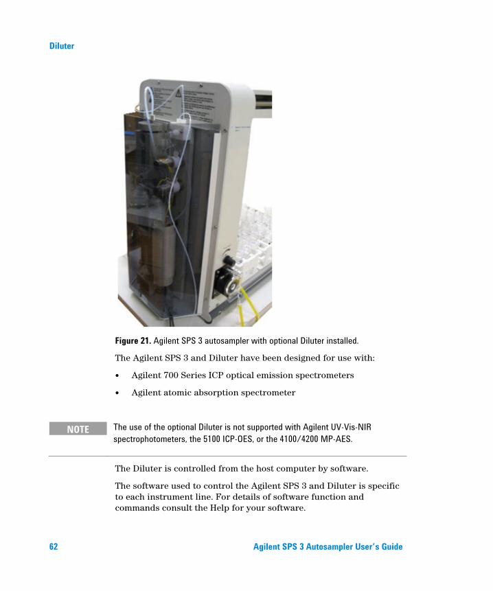
Figure 21. Agilent SPS 3 autosampler with optional Diluter installed.
The Agilent SPS 3 and Diluter have been designed for use with:
Agilent 700 Series ICP optical emission spectrometers
Agilent atomic absorption spectrometer
NOTE The use of the optional Diluter is not supported with Agilent UV-Vis-NIR spectrophotometers, the 5100 ICP-OES, or the 4100/4200 MP-AES.
The Diluter is controlled from the host computer by software.
The software used to control the Agilent SPS 3 and Diluter is specific to each instrument line. For details of software function and commands consult the Help for your software.

Diluter
Agilent SPS 3 Autosampler User’s Guide 63
The Agilent SPS 3 and Diluter can be used:
Online – connected to an instrument to perform sampling/dilution interleaved with analysis or
Offline – connected only to the host computer to prepare samples
NOTE An optional software package (RoboPrep) is required for offline sample and standard preparation. Contact your local Agilent representative for further information.
Specifications
Dilution Performance For a 1:20 dilution to 20 mL total volume, dilution error of < 2%.
Environmental
Table 7. Suitable environmental conditions for the Agilent SPS 3 autosampler and Diluter.
Condition Altitude Temp (°C) Humidity (%RH) non-condensing
Non-operating (Transport)
0–2133 m (0–7000 ft)
5–45 20–80
Operating within specifications
0–853 m (0–2800 ft) 853–2133 m (2800–7000 ft)
10–35 10–25
8–80

Diluter
64 Agilent SPS 3 Autosampler User’s Guide
Weights and Dimensions
Table 8. Weights and dimensions
System unit Width Depth Height Weight
Diluter for Agilent SPS 3 autosampler (includes mounting bracket)
260 mm 10.2 in.
84 mm 3.3 in.
503 mm 19.8 in.
3.5 kg 7.7 lb
Agilent SPS 3 autosampler with Diluter installed
572 mm 22.5 in.
285 mm 11.2 in.
510 mm 20.1 in.
18 kg 39.7 lb
Connections Making connections to the optional Diluter:
1 Ensure that the tubing from the sample probe and main instrument are as shown in Figure 22.
Figure 22. Connections to the sample probe and main instrument.
From the sample probe
Solenoid #1
To the instrument
Manifold block

Diluter
Agilent SPS 3 Autosampler User’s Guide 65
2 Place the two PTFE tubes attached to the bottom of the Diluter in a suitable diluent container. Check that you have filled this container with an appropriate diluent.
Figure 23. Diluter tubing configuration.
Stepper motor block
Leadscrew coupling assembly
Opto PWB assembly
PTFE storage coil
Solenoid #2
Solenoid #1
SPS 3 Probe Instrument
Diluent container
Syringe
Manifold block

Diluter
66 Agilent SPS 3 Autosampler User’s Guide
Theory of Operation The heart of the Diluter is a motor-driven syringe that collects and dispenses accurately measured volumes. The syringe is a precision component whose maximum volume is 20 mL.
To enable the Diluter to function with samples that may be highly corrosive, an inert storage coil is used. Collected samples are stored in this coil and never enter the syringe (only the rinse liquid enters the syringe).
To prevent mixing or diffusing of samples which may be in the storage coil at any one time an air slug is drawn into the coil to separate each sample.
Figure 24. System diagram of the Diluter

Diluter
Agilent SPS 3 Autosampler User’s Guide 67
Two solenoid valves are used in the Diluter to enable the collection and dispensing of samples and diluent. Solenoid #1 is energized in normal operation with flow from the sample probe directly to the instrument. During dilution it is unenergized and Solenoid #2 is energized to allow the syringe to draw sample from the probe line and deliver sample and diluent to the dilution tube via the probe.
NOTE To ensure the correct amount of diluent is delivered to the target test tube during a dilution, the storage coil and sample probe must be completely filled with rinse/diluent prior to dilution. This is achieved by priming the coil and probe using the ‘Prime’ command in the software. Priming must be performed until it is observed that no air bubbles are expelled from the probe tip. The Agilent SPS 3 will perform an automatic prime when the software senses the presence of the Diluter. This initial prime lasts for three cycles.
Mixing is performed by drawing the solution from the sample vessel into the syringe and then expelling it back into the test tube through the probe. There are default settings for the number of repetitions that are performed and the probe height at which the solution is expelled.
The default values vary depending on the volume of the test tube being used. You can also program your own mix settings using the instrument’s software.
Table 9. Typical settings.
Parameter Setting
Number of rinsing cycles 1
Sampling height (mm) 50
Sampling volume (mL) 10
Sampling rate (mL/min) 3
Dispensing height (mm) 50
Dispensing rate (mL/min) 13

Diluter
68 Agilent SPS 3 Autosampler User’s Guide
This page is intentionally left blank.


www.agilent.com
In This Book The manual describes the following:
Safety Practices and Hazards
Introduction
Installation
Operation
Maintenance Procedures
Instrument Cleaning
Troubleshooting
Diluter Plumbing and Operation
© Agilent Technologies 2003, 2006,
2009-2012, 2014
09/12
*8510207700* *8510207700*
8510207700 Issue 8