Embed Size (px)
Citation preview

Agilent N9320ASpectrum AnalyzerTechnical Overview
All the essentials of an Agilent spectrum analyzerwith a price/performance
that's easy to affordN9320A Spectrum Analyzer
· 9 kHz to 3 GHz range· 10 Hz to 1 MHz RBW · –148 dBm DANL with pre-amp· 9.2 ms non-zero span sweep time· +13 dBm third-order intercept
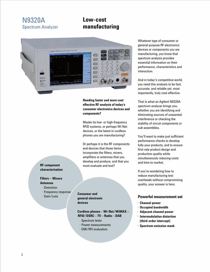
Low-costmanufacturing
Needing faster and more cost effective RF analysis of today's consumer electronics devices and components?
Maybe its low- or high-frequency RFID systems, or perhaps Wi-Net devices, or the latest in cordless phones you are manufacturing?
Or perhaps it is the RF components and devices that these items incorporate the filters, mixers, amplifiers or antennas that you develop and produce, and that you must evaluate and test?
Whatever type of consumer or general-purpose RF electronics devices or components you are manufacturing, you know that spectrum analysis provides essential information on their performance, characteristics and interaction.
And in today's competitive world, you need this analysis to be fast, accurate, and reliable yet, most importantly, truly cost-effective.
That is what an Agilent N9320A spectrum analyzer brings you, whether you are identifying and eliminating sources of unwanted interference or checking the stability of circuit components or sub-assemblies.
You'll want to make just sufficient performance checks to develop fully your products, and to ensure first-rate product design and production quality while simultaneously reducing costs and time to market.
If you're wondering how to reduce manufacturing test overheads without compromising quality, your answer is here.
Powerful measurement set
· Channel power· Occupied bandwidth· Adjacent channel power· Intermodulation distortion
(third-order intercept)
· Spectrum emission mask
RF componentcharacterization
Filters – MixersAntennas
· Distortion· Frequency response· Gain/Loss
2
Consumer and general electronic devices
Cordless phones – Wi-Net/WiMAX –RFID/DSRC – TV – Radio – DAB
· Spectrum tests· Power measurements· EMI/RFI evaluation
N9320A Spectrum Analyzer
N9320ASpectrum Analyzer
Power measurements made easy using the measurement suite
One of the most fundamental measurements performed by spectrum analyzers is the frequency-domain measurement of RF power. However, detailed analysis of a signal often requires standards-defined spectral mask tests or more complex power/bandwidth measurement combinations.
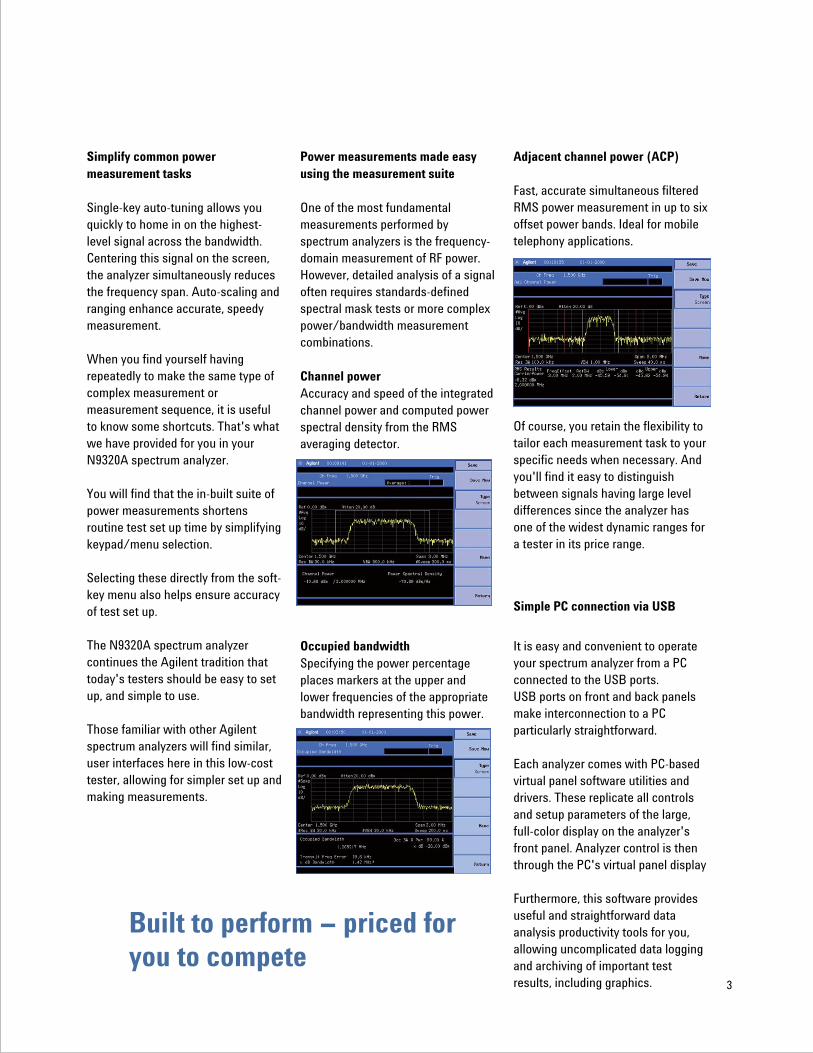
Channel powerAccuracy and speed of the integrated channel power and computed power spectral density from the RMS averaging detector.
Occupied bandwidthSpecifying the power percentage places markers at the upper and lower frequencies of the appropriate bandwidth representing this power.
Simplify common power measurement tasks
Single-key auto-tuning allows you quickly to home in on the highest-level signal across the bandwidth. Centering this signal on the screen, the analyzer simultaneously reduces the frequency span. Auto-scaling and ranging enhance accurate, speedy measurement.
When you find yourself having repeatedly to make the same type of complex measurement or measurement sequence, it is useful to know some shortcuts. That's what we have provided for you in your N9320A spectrum analyzer.
You will find that the in-built suite of power measurements shortens routine test set up time by simplifying keypad/menu selection.
Selecting these directly from the soft-key menu also helps ensure accuracy of test set up.
The N9320A spectrum analyzer continues the Agilent tradition that today's testers should be easy to set up, and simple to use.
Those familiar with other Agilent spectrum analyzers will find similar, user interfaces here in this low-cost tester, allowing for simpler set up and making measurements.
Adjacent channel power (ACP)
Fast, accurate simultaneous filtered RMS power measurement in up to six offset power bands. Ideal for mobile telephony applications.
Of course, you retain the flexibility to tailor each measurement task to your specific needs when necessary. And you'll find it easy to distinguish between signals having large level differences since the analyzer has one of the widest dynamic ranges for a tester in its price range.
Simple PC connection via USB
It is easy and convenient to operate your spectrum analyzer from a PC connected to the USB ports. USB ports on front and back panels make interconnection to a PC particularly straightforward.
Each analyzer comes with PC-based virtual panel software utilities and drivers. These replicate all controls and setup parameters of the large, full-color display on the analyzer's front panel. Analyzer control is then through the PC's virtual panel display
Furthermore, this software provides useful and straightforward data analysis productivity tools for you, allowing uncomplicated data logging and archiving of important test results, including graphics.
Built to perform priced for you to compete
3
When it comes to receiving the best return from your R&D equipment budget, turn to Agilent's new generation of low-cost sources and analyzers.
An effective, professional field installation and maintenance tool
Most installation and maintenance tasks demand fast, cost effective test solutions. Being small and lightweight, an N9320A spectrum analyzer is as functional and indispensable in low-cost bench repair applications as it is for field troubleshooting.
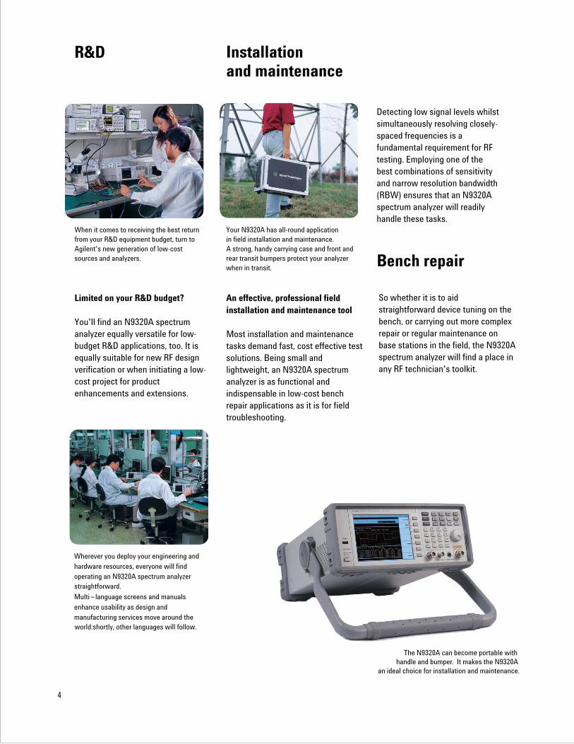
Your N9320A has all-round application in field installation and maintenance.A strong, handy carrying case and front and rear transit bumpers protect your analyzer when in transit.
So whether it is to aid straightforward device tuning on the bench, or carrying out more complex repair or regular maintenance on base stations in the field, the N9320A spectrum analyzer will find a place in any RF technician's toolkit.
R&D Installationand maintenance
Bench repair
Limited on your R&D budget?
You'll find an N9320A spectrum analyzer equally versatile for low-budget R&D applications, too. It is equally suitable for new RF design verification or when initiating a low-cost project for product enhancements and extensions.
Detecting low signal levels whilst simultaneously resolving closely-spaced frequencies is a fundamental requirement for RF testing. Employing one of the best combinations of sensitivity and narrow resolution bandwidth (RBW) ensures that an N9320A spectrum analyzer will readily handle these tasks.
4
Wherever you deploy your engineering and hardware resources, everyone will find operating an N9320A spectrum analyzer
Multi language screens and manualsenhance usability as design andmanufacturing services move around the
straightforward.
world:shortly, other languages will follow.
The N9320A can become portable withhandle and bumper. It makes the N9320A
an ideal choice for installation and maintenance.
–
Education
Using Agilent test equipment in your educational establishment guarantees you are upholding the highest standards for the future, for tomorrow's engineers.
Now you have the opportunity to put Agilent's renowned quality and precision into every student's hands.
Help your students and trainees gain the edge. There is now no need to compromise on the quality of their test equipment.
Educators hold Agilent testers in the highest esteem. Therefore, you can be confident and proud of your standards in the classroom: and your students will have confidence in their experimental results. Your students will be able to focus on RF circuit experimentation and signal analysis exercises, because spectrum analyzer operation is straightforward.
You'll find it has sufficient performance for many basic research projects, too, where you need an inexpensive, fast, high-quality, general-purpose RF signal analyzer.
Take a closer look see how cost-effective spectrum analysis performance can really be
You'll find an Agilent N9320A spectrum analyzer
provides outstanding measurement speed and
performance for its price – check out its
availability today and buy with confidence.
Learning how to use test instrumentation, and understanding how RF signal interact are fundamentals for electronics studies. Spectrum analysis is one test essential to good circuit design. It brings signal interactions to light for students and helps explain signal mixing processes.
The keen price/performance combination in this spectrum analyzer, part of the low-cost series from Agilent Technologies, means that you do not need to limit students to one or two pieces of equipment to a class.
Affordable, fast support
When you rely on Agilent test equipment for your manufacturing process, installation procedures, or maintenance programs, you need to know that you can call on superior customer support in case of problems.
Buying test equipment from Agilent's new low-cost series puts you in touch with top-line service and support should you need it. So, you can be confident that you are making the right choice for the right price.
5
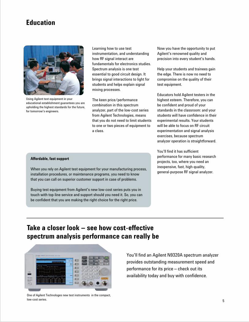
One of Agilent Technologes new test instruments in the compact,low-cost series.
Specifications
Specifications apply under the following conditions:
· After a warm-up time of 45 minutes,
· At an ambient temperature specified in the data sheet,
and within a valid calibration period.
6
Range: 9 kHz to 3 GHz AC coupled100 kHz to 3 GHz Preamp on
Set-up resolution: 1 Hz
Aging rate: ±1 ppm / yearTemperature stability: ±1 ppm 0 °C to +50 °C; reference 25 °C
Supply voltage stability: ± 0.3 ppm ± 5 %
Marker resolution: (frequency span)/(number of sweep points – 1)
Uncertainty: ± (frequency indication x frequency reference uncertainty*+1% x span + 20% xresolution bandwidth + marker resolution)
Resolution: 0.1 Hz, 1 Hz, 10 Hz, 100 Hz, 1 kHz SelectableAccuracy: ±{(marker frequency) RBW/span 0.02;
(frequency reference uncertainty*) Marker level to displayed noise level>30 dB(RBW 1 kHz)+ (counter resolution)} Marker level to displayed noise level>40 dB (RBW<1 kHz)
Range: 0 Hz (zero span), 100 Hz to 3 GHz. Resolution: 1 Hz
Accuracy: ±(1 % of span) + 2(span/460)
Offset from CW signal: fc = 1 GHz; 10 kHz: < 88 dBc/Hz
< 90 dBc/Hz Typical100 kHz: < 100 dBc/Hz
< 102 dBc/Hz Typical1 MHz: < 110 dBc/Hz
< 112 dBc/Hz Typical
100 Hz peak to peak in 100 ms 1 kHz RBW, 1 kHz VBW
10 Hz to 1 MHz in 1-3-10 sequence –3 dB bandwidthAccuracy: ±20 % 1 kHz to 1 MHz RBW
±5 % 10 Hz to 300 Hz RBW
Resolution filter shape factor: < 15 Nominal ; 3 kHz to 1 MHz RBW
< 5 Nominal ; 10 Hz to 300 Hz RBW
Supplemental information
Frequency
Frequency
Internal 10 MHz frequency reference
Frequency readout accuracy (start, stop, center, marker)
Marker frequency counter
Frequency span
Phase noise
Residual FM
Resolution bandwidth (RBW)
*Frequency reference uncertainty = (aging rate)(period since adjustment) +
(Supply voltage stability) + (temperature stability).
< 20 Nominal; 1 kHz RBW
7
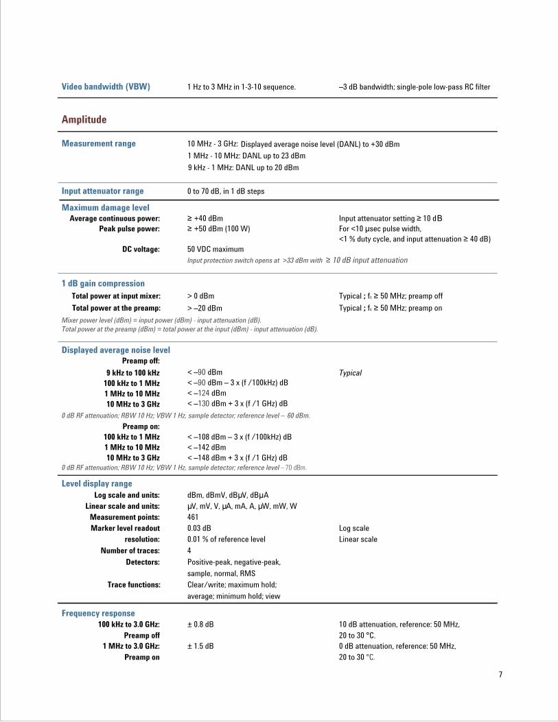
Video bandwidth (VBW)
Measurement range
Input attenuator range
Maximum damage level
1 dB gain compression
Displayed average noise level
Level display range
Frequency response
1 Hz to 3 MHz in 1-3-10 sequence. –3 dB bandwidth; single-pole low-pass RC filter
10 MHz - 3 GHz: Displayed average noise level (DANL) to +30 dBm
0 to 70 dB, in 1 dB steps
Average continuous power: +40 dBm Input attenuator setting 10 dBPeak pulse power: +50 dBm (100 W) For <10 sec pulse width,
<1 % duty cycle, and input attenuation 40 dB)DC voltage: 50 VDC maximum
Total power at input mixer: > 0 dBm Typical ; fc 50 MHz; preamp off
Total power at the preamp: > –20 dBm Typical ; fc 50 MHz; preamp on
Preamp off: < –90 dBm9 kHz to 100 kHz Typical< –90 dBm – 3 x (f /100kHz) dB100 kHz to 1 MHz< –124 dBm1 MHz to 10 MHz< –130 dBm + 3 x (f /1 GHz) dB10 MHz to 3 GHz
Preamp on:100 kHz to 1 MHz < –108 dBm – 3 x (f /100kHz) dB1 MHz to 10 MHz < –142 dBm 10 MHz to 3 GHz < –148 dBm + 3 x (f /1 GHz) dB
Log scale and units: dBm, dBmV, dB V, dB ALinear scale and units: V, mV, V, A, mA, A, W, mW, W
Measurement points: 461Marker level readout 0.03 dB Log scale
resolution: 0.01 % of reference level Linear scale
Number of traces: 4
Detectors: Positive-peak, negative-peak,
sample, normal, RMSTrace functions: Clear/write; maximum hold;
average; minimum hold; view
100 kHz to 3.0 GHz: ± 0.8 dB 10 dB attenuation, reference: 50 MHz, Preamp off 20 to 30 °C.
1 MHz to 3.0 GHz: ± 1.5 dB 0 dB attenuation, reference: 50 MHz, Preamp on 20 to 30 °C.
Amplitude
Input protection switch opens at >33 dBm with 10 dB input attenuation
Mixer power level (dBm) = input power (dBm) - input attenuation (dB).Total power at the preamp (dBm) = total power at the input (dBm) - input attenuation (dB).
0 dB RF attenuation; RBW 10 Hz; VBW 1 Hz, sample detector; reference level – 60 dBm.
0 dB RF attenuation; RBW 10 Hz; VBW 1 Hz, sample detector; reference level – 70 dBm.
9 kHz - 1 MHz: DANL up to 20 dBm
1 MHz - 10 MHz: DANL up to 23 dBm
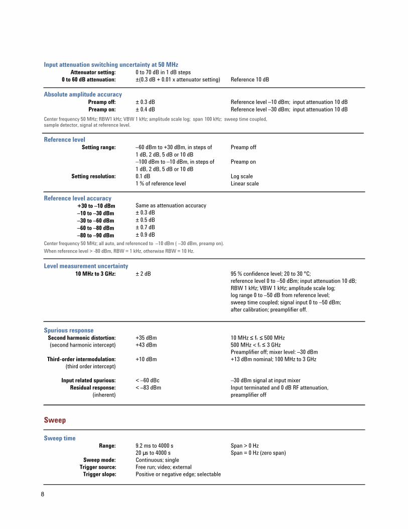
Input attenuation switching uncertainty at 50 MHz
Absolute amplitude accuracy
Reference level
Reference level accuracy
Level measurement uncertainty
Spurious response
Sweep time
Attenuator setting: 0 to 70 dB in 1 dB steps0 to 60 dB attenuation: ±(0.3 dB + 0.01 x attenuator setting) Reference 10 dB
Preamp off: ± 0.3 dB Reference level –10 dBm; input attenuation 10 dBPreamp on: ± 0.4 dB Reference level –30 dBm; input attenuation 10 dB
Setting range: –60 dBm to +30 dBm, in steps of Preamp off1 dB, 2 dB, 5 dB or 10 dB–100 dBm to –10 dBm, in steps of Preamp on1 dB, 2 dB, 5 dB or 10 dB
Setting resolution: 0.1 dB Log scale1 % of reference level Linear scale
Same as attenuation accuracy+30 to –10 dBm± 0.3 dB–10 to –30 dBm± 0.5 dB–30 to –60 dBm ± 0.7 dB–60 to –80 dBm ± 0.9 dB–80 to –90 dBm
10 MHz to 3 GHz: ± 2 dB 95 % confidence level; 20 to 30 °C;reference level 0 to –50 dBm; input attenuation 10 dB; RBW 1 kHz; VBW 1 kHz; amplitude scale log; log range 0 to –50 dB from reference level; sweep time coupled; signal input 0 to –50 dBm; after calibration; preamplifier off.
Second harmonic distortion: +35 dBm 10 MHz fc 500 MHz(second harmonic intercept) +43 dBm 500 MHz fc 3 GHz
Preamplifier off; mixer level: –30 dBmThird-order intermodulation: +10 dBm +13 dBm nominal; 100 MHz to 3 GHz
(third order intercept)
Input related spurious: < –60 dBc –30 dBm signal at input mixerResidual response: < –83 dBm Input terminated and 0 dB RF attenuation,
(inherent) preamplifier off
Range: 9.2 ms to 4000 s Span > 0 Hz20 s to 4000 s Span = 0 Hz (zero span)
Sweep mode: Continuous; singleTrigger source: Free run; video; external
Trigger slope: Positive or negative edge; selectable
Csample detector, signal at reference level.
enter frequency 50 MHz; RBW1 kHz; VBW 1 kHz; amplitude scale log; span 100 kHz; sweep time coupled,
Center frequency 50 MHz; all auto, and referenced to –10 dBm ( –30 dBm, preamp on).
When reference level > -80 dBm, RBW = 1 kHz, otherwise RBW = 10 Hz.
Sweep
8
<

9
Tracking generator source output (optional)
10 MHz reference output
10 MHz reference input
Warm-up: 45 minutesOutput frequency range: 9 kHz to 3.0 GHz
Output power levelRange: –30 dBm to 0 dBm in 0.1 dB steps
Absolute accuracy: ± 0.75 dB 20 to 30 °C, at 50 MHz with coupled sourceattenuator, referenced to –20 dBm
Output flatness: Referenced to 50 MHz,
100 kHz to 10 MHz ± 3 dB
–20 d Bm
10 MHz to 3 GHz ± 2 dBConnector and impedance: N-type female; 50 ohm
VSWR: < 1.5 : 1 100 kHz to 3.0 GHz, input attenuator 12 dB
Output amplitude: >0 dBm
Connector and
Input amplitude: –5 dBm to +10 dBm
Frequency lock range: ±5 ppm of specified external
reference input frequency
Connector and
Rear panel input/output connections
Output Impedance: BNC-type female; 50 ohm
input impedance: BNC-type female; 50 ohm
Calibration output
Probe power
USB host
Amplitude: –10 dBm ± 0.3 dB
Frequency: 50 MHz
Accuracy: Same as frequency reference
Connector and impedance: BNC-type female; 50 ohm
Voltage/current: +15 V, 150 mA max
–12.6 V, 150 mA max
Connector and protocol: A plug; Version 1.1
RF Input Connector and impedance: N-type female; 50 ohm
VSWR: <1.5 : 1 100 kHz to 3.0 GHz, input attenuator 10 dB
Front panel input/output

External trigger input
VGA output:
Input amplitude: 5 V TTL levelConnector and
VGA analog RGB 31.5 kHz horizontal, 60 Hz vertical sync rates; non-interlaced
Connector: D-sub 15-pin female VGA compatibleScreen resolution: 640 x 480
Internal data storage: 16 MB nominal
Power supply: 100-240 VAC; 50 to 60 Hz Auto-ranging
Power consumption: < 65 W
Warm-up time: 45 minute
Temperature range: +0 °C to + 45 °C Operating–20 °C to + 70 °C Storage
Weight: 9.1 kg (20 lb) Net approximately; without options
Dimensions: 132.5 x 320 x 400 mm Approximately; without handle5.2 x 12.6 x 15.7 in
Input impedance: BNC-type female; 10 k ohm
General
10
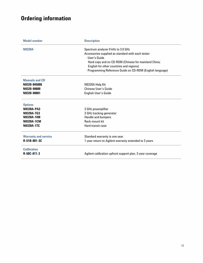
Ordering information
11
Model number Description
N9320A Spectrum analyzer 9 kHz to 3.0 GHzAccessories supplied as standard with each tester:
· User's Guide Hard copy and on CD-ROM (Chinese for mainland China; English for other countries and regions)
· Programming Reference Guide on CD-ROM (English language)
Manuals and CDN9320-845000 N9320A Help KitN9320-90000 Chinese User’s GuideN9320-90001 English User’s Guide
Warranty and service
Calibration
OptionsN9320A-PA3 3 GHz preamplifier
N9320A-1HB Handle and bumpersN9320A-1CM Rack-mount kitN9320A-1TC Hard transit case
Standard warranty is one year.R-51B-001-3C 1-year return-to-Agilent warranty extended to 3 years
R-50C-011-3 Agilent calibration upfront support plan, 3-year coverage
N9320A-TG3 3 GHz tracking generator

Agilent Technologies related product for manufacturing test, field maintenance and education
N9310A RF Signal Generator
Low-cost signal generator covering 9 kHz to 3 GHz, with I/Q modulation: an ideal companion signal source for the N9320A spectrum analyzer.
Find out today how other Agilent products will help solve your test needs.
www.agilent.comFor more information on Agilent Technologies' products, applications or services, please contact your local Agilent office.
United States:(tel) +1 800 452-4444(fax) +1 800 452-4433
Canada:(tel) +1 877 894 4414(fax) +1 905 282-6495
Latin America:(tel) +1 305 269-7500(fax) +1 305 269-7599
Europe:(tel) +31 (0)20 547 2323(fax) +31 (0)20 547 2390
www.agilent.com/find/assistOnline assistance:
Japan:(tel) +81 426 56 7832(fax) +81 426 56 7840
Australia:(tel) 1 800 629 485(fax) +61 3 9210 5947
New Zealand:(tel) 0 800 738 378(fax) +64 4 495 8950
Asia Pacific:(tel) +852 3197 7777(fax) +852 2506 9284
Microsoft and Windows are U.S. registered trademarks of Microsoft Corporation.
Product specifications and descriptions in this document are subject to change without notice.
Copyright 2006 Agilent TechnologiesPrinted in USA, December 01, 2007
PN 5989-5521EN
Remove all doubtOur repair and calibration services will get
your equipment back to you, performing
like new, when promised. You will get
full value out of your Agilent equipment
throughout its lifetime. Your equipment
will be serviced by Agilent-trained techni-
cians using the latest factory calibration
procedures, automated repair diagnostics
and genuine parts. You will always have the
utmost confidence in your measurements.
Agilent offers a wide range of additional
expert test and measurement services for
your equipment, including initial start-up
assistance onsite education and training,
as well as design, system integration, and
project management.
For more information on repair and
calibration services, go to
www.agilent.com/find/removealldoubt
www.agilent.com/find/emailupdates
Get the latest information on the products
and applications you select.
www.agilent.com/find/open
Agilent Open simplifies the process of
connecting and programming test systems
to help engineers design, validate and
manufacture electronic products. Agilent
offers open connectivity for a broad range
of system-ready instruments, open industry
software, PC-standard I/O and global sup-
port, which are combined to more easily
integrate test system development.
Agilent Email Updates
AgilentOpen