Embed Size (px)
Citation preview
Agilent 8900 Triple Quadrupole ICP-MS
Site Preparation Checklist
Agilent Technologies
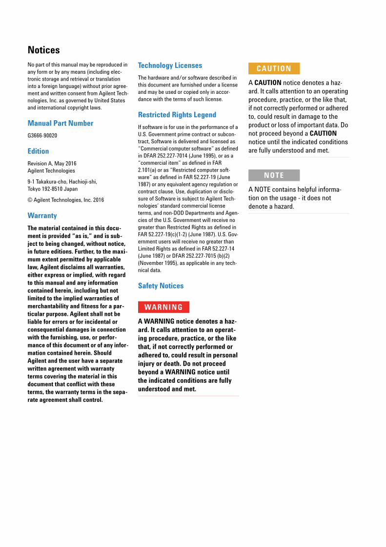
NoticesNo part of this manual may be reproduced in any form or by any means (including elec-tronic storage and retrieval or translation into a foreign language) without prior agree-ment and written consent from Agilent Tech-nologies, Inc. as governed by United States and international copyright laws.
Manual Part Number
G3666-90020
Edition
Revision A, May 2016Agilent Technologies
9-1 Takakura-cho, Hachioji-shi, Tokyo 192-8510 Japan
© Agilent Technologies, Inc. 2016
Warranty
The material contained in this docu-ment is provided “as is,” and is sub-ject to being changed, without notice, in future editions. Further, to the maxi-mum extent permitted by applicable law, Agilent disclaims all warranties, either express or implied, with regard to this manual and any information contained herein, including but not limited to the implied warranties of merchantability and fitness for a par-ticular purpose. Agilent shall not be liable for errors or for incidental or consequential damages in connection with the furnishing, use, or perfor-mance of this document or of any infor-mation contained herein. Should Agilent and the user have a separate written agreement with warranty terms covering the material in this document that conflict with these terms, the warranty terms in the sepa-rate agreement shall control.
Technology Licenses
The hardware and/or software described in this document are furnished under a license and may be used or copied only in accor-dance with the terms of such license.
Restricted Rights Legend
If software is for use in the performance of a U.S. Government prime contract or subcon-tract, Software is delivered and licensed as “Commercial computer software” as defined in DFAR 252.227-7014 (June 1995), or as a “commercial item” as defined in FAR 2.101(a) or as “Restricted computer soft-ware” as defined in FAR 52.227-19 (June 1987) or any equivalent agency regulation or contract clause. Use, duplication or disclo-sure of Software is subject to Agilent Tech-nologies’ standard commercial license terms, and non-DOD Departments and Agen-cies of the U.S. Government will receive no greater than Restricted Rights as defined in FAR 52.227-19(c)(1-2) (June 1987). U.S. Gov-ernment users will receive no greater than Limited Rights as defined in FAR 52.227-14 (June 1987) or DFAR 252.227-7015 (b)(2) (November 1995), as applicable in any tech-nical data.
Safety Notices
WARNING
A WARNING notice denotes a haz-ard. It calls attention to an operat-ing procedure, practice, or the like that, if not correctly performed or adhered to, could result in personal injury or death. Do not proceed beyond a WARNING notice until the indicated conditions are fully understood and met.
CAUTION
A CAUTION notice denotes a haz-ard. It calls attention to an operating procedure, practice, or the like that, if not correctly performed or adhered to, could result in damage to the product or loss of important data. Do not proceed beyond a CAUTION notice until the indicated conditions are fully understood and met.
NOTE
A NOTE contains helpful informa-tion on the usage - it does not denote a hazard.
Agilent 8900 Triple Quadrupole ICP-MS Site Preparation Checklist 3
Contents
Contents
Checklist and Requirement Summary 5
Customer Responsibilities 5
Important Customer Information 6
Space, Weight and Access Requirements 7
Environmental Conditions and Site Requirements 10
Power Consumption and Configuration 13
Cooling Water Requirements 15
Gas Requirements 16
Essential Requirements for Cell Gas Installation 17
Communications 19
Laboratory Supply Requirements 20
Other Requirements 21
Important Customer Web Links 22
Appendix 23
Detailed Environmental Conditions and Site Requirements 23
Detailed Power Consumption and Configuration 25
Detailed Cooling Water Requirements and Operating Supplies 30
Detailed Gas Requirements 31

4
Contents
This page is intentionally left blank.
Agilent 8900 Triple Quadrupole ICP-MS Site Preparation Checklist
Checklist and Requirement Summary
Agilent 8900 Triple Q
Thank you for purchasing an Agilent instrument. To get you started and to assure a successful and timely installation, please refer to this specification or set of requirements.
Correct site preparation is the first key step in ensuring that your instruments and software systems operate reliably over an extended lifetime. This document is an information guide AND checklist prepared for you that outlines the supplies, consumables, space and utility requirements for your equipment for your site.
Customer Responsibilities
Make sure your site meets the following prior specifications before the installation date. This checklist includes information on this product G3665A. For details, see specific sections within this checklist, including:
The necessary laboratory or bench space is available. Refer to "Space, Weight and Access Requirements" on page 7.
The environmental conditions for the lab as well as laboratory gases and plumbing. Refer to "Environmental Conditions and Site Requirements" on page 10.
The power requirements related to the product (e.g., number & location of electrical outlets). Refer to "Power Consumption and Configuration" on page 13.
The cooling water requirements for the product and installation. Refer to "Cooling Water Requirements" on page 15.
The gas requirements for the product and installation. Refer to "Gas Requirements" on page 16.
The required network communication configuration. Refer to "Communications" on page 19.
The required items and tools necessary for the product and installation. Refer to "Laboratory Supply Requirements" on page 20.
For other product specific information, refer to "Other Requirements" on page 21.
Agilent Technologies service providers will not install your Agilent ICP- MS system until an adequate exhaust system is present and functioning. Refer to "Environmental Conditions and Site Requirements" on page 10.
If Agilent is delivering installation and familiarization services, users of the instrument should be present throughout these services; otherwise, they will miss important operational, maintenance and safety information.
uadrupole ICP-MS Site Preparation Checklist 5
Important Customer Information
6
1 If you have questions or problems in providing anything described as part of the Customer Responsibilities above, please contact your local Agilent or partner support/service organization for assistance prior to delivery. In addition, Agilent and/or its partners reserve the right to reschedule the installation dependent upon the readiness of your laboratory.
2 Should your site not be ready for whatever reasons, please contact Agilent as soon as possible to re- arrange any services that have been purchased.
3 Other optional services such as additional training, operational qualification (OQ) and consultation for user- specific applications may also be provided at the time of installation when ordered with the system, but should be contracted separately.
Agilent 8900 Triple Quadrupole ICP-MS Site Preparation Checklist
Space, Weight and Access Requirements
Agilent 8900 Triple Q
Identify the laboratory bench space before your system arrives based on the information in Table 2.
Pay special attention to the total height and total weight requirements for all system components you have ordered and avoid bench space with overhanging shelves. Also pay special attention to the total weight of the modules you have ordered to ensure your laboratory bench can support this weight.
Special Notes
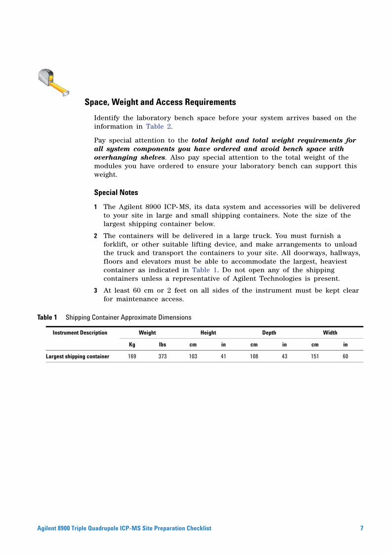
1 The Agilent 8900 ICP- MS, its data system and accessories will be delivered to your site in large and small shipping containers. Note the size of the largest shipping container below.
2 The containers will be delivered in a large truck. You must furnish a forklift, or other suitable lifting device, and make arrangements to unload the truck and transport the containers to your site. All doorways, hallways, floors and elevators must be able to accommodate the largest, heaviest container as indicated in Table 1. Do not open any of the shipping containers unless a representative of Agilent Technologies is present.
3 At least 60 cm or 2 feet on all sides of the instrument must be kept clear for maintenance access.
Container Approximate Dimensions
Table 1 ShippingInstrument Description Weight Height Depth Width
Kg lbs cm in cm in cm in
Largest shipping container 169 373 103 41 108 43 151 60
uadrupole ICP-MS Site Preparation Checklist 7
8
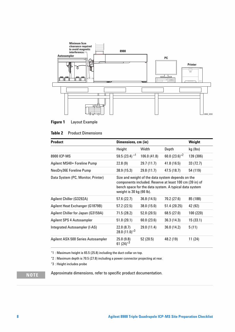
Figure 1 Layout Example
*1 : Maximum height is 65.5 (25.8) including the duct collar on top.
*2 : Maximum depth is 70.5 (27.8) including a power connector projecting at rear.
*3 : Height includes probe
Table 2 Product Dimensions
Product Dimensions, cm (in) Weight
Height Width Depth kg (lbs)
8900 ICP-MS 59.5 (23.4) *1 106.0 (41.8) 60.0 (23.6)*2 139 (306)
Agilent MS40+ Foreline Pump 22.8 (9) 29.7 (11.7) 41.8 (16.5) 33 (72.7)
NeoDry36E Foreline Pump 38.9 (15.3) 29.8 (11.7) 47.5 (18.7) 54 (119)
Data System (PC, Monitor, Printer) Size and weight of the data system depends on the components included. Reserve at least 100 cm (39 in) of bench space for the data system. A typical data system weight is 30 kg (66 lb).
Agilent Chiller (G3292A) 57.6 (22.7) 36.8 (14.5) 70.2 (27.6) 85 (188)
Agilent Heat Exchanger (G1879B) 57.2 (22.5) 38.0 (15.0) 51.4 (20.25) 42 (92)
Agilent Chiller for Japan (G3159A) 71.5 (28.2) 52.0 (20.5) 68.5 (27.0) 100 (220)
Agilent SPS 4 Autosampler 51.0 (20.1) 60.0 (23.6) 36.3 (14.3) 15 (33.1)
Integrated Autosampler (I-AS) 22.0 (8.7) 28.0 (11.0)*3
29.0 (11.4) 36.0 (14.2) 5 (11)
Agilent ASX-500 Series Autosampler 25.0 (9.8) 61 (24)*3
52 (20.5) 48.2 (19) 11 (24)
8900_0393
8900
PC
Printer
Minimum 5cm clearance requiredto avoid magnetic interference.
Autosampler
Approximate dimensions, refer to specific product documentation.
NOTEAgilent 8900 Triple Quadrupole ICP-MS Site Preparation Checklist
Agilent 8900 Triple Q
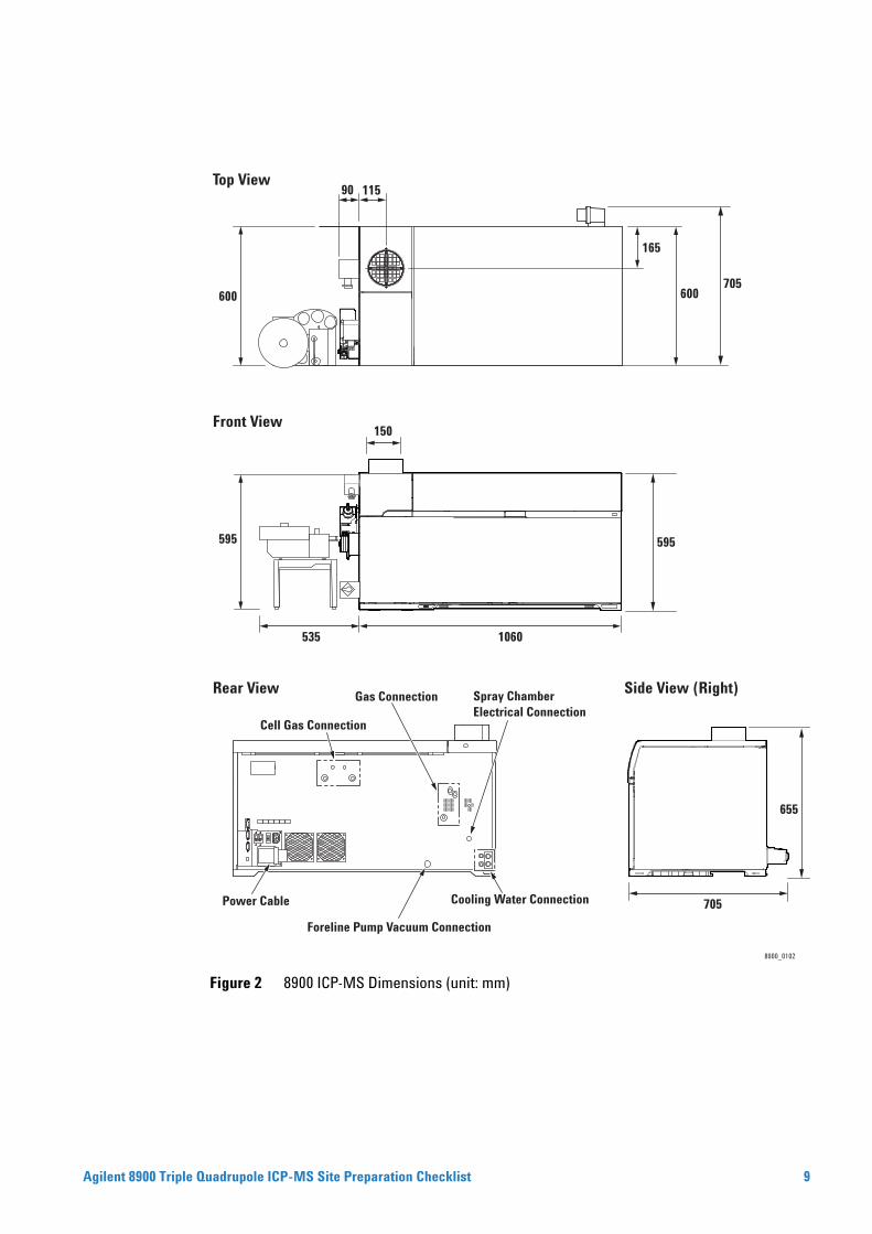
Figure 2 8900 ICP-MS Dimensions (unit: mm)
8900_0102
Side View (Right)
Front View
Top View
Rear View
Cooling Water Connection
600
165
600
115
Cell Gas Connection
Gas Connection
Power Cable
Foreline Pump Vacuum Connection
Spray Chamber Electrical Connection
705
90
705
655
150
595
535 1060
595
uadrupole ICP-MS Site Preparation Checklist 9
Environmental Conditions and Site Requirements
10
Operating your instrument within the recommended temperature ranges insures optimum instrument performance and lifetime.
Special Notes
1 Performance can be affected by sources of heat and cold (e.g., direct sunlight, heating/cooling from air conditioning outlets, drafts and/or vibrations). The site’s ambient temperature conditions must be stable for optimum performance.
2 The customer is responsible for supplying the ductwork between the instrument and the lab extraction system.
Asphyxiation Hazard
WARNINGLaboratory must be equipped with ventilation system to supply continuous and sufficient fresh air from outside to prevent user from asphyxiation.Health Hazard, Asphyxiation Hazard
WARNINGLaboratory must be equipped with exhaust system to remove harmful gases via a scrubber system to outside of the laboratory, to prevent user from asphyxiation. User safety requires that the exhaust gases from the plasma and vacuum systems be vented externally to the building and not recirculated by the environmental control system. Health hazards include chemical toxicity of solvents, samples, and foreline pump fluid vapor.Table 3 Temperature and Humidity Specifications
Parameter Specification
Temperature 15-30 °C (59-86 °F) < 2 °C/h change and total change should be < 5 °C
Humidity 20-80 %
Altitude Up to 2,000 m
Atmosphere Non Condensing; Non Corrosive
Table 4 Heat Output
Product Heat Dissipated (W) Heat Absorbed (W)
8900 ICP-MS 3,600
Foreline Pump 500
PC/Monitor 430
Heat Exchanger (50/60 Hz) 2,000 (Maximum) 1,600 (2,000 maximum)
Agilent Chiller (G3292 A) 50/60 Hz 3,200 (Maximum) 1,600 (2,000 maximum)
Agilent 8900 Triple Quadrupole ICP-MS Site Preparation Checklist
Agilent 8900 Triple Q
Extraction Vent 1,600 (2,500 maximum)
Table 4 Heat Output (continued)
Product Heat Dissipated (W) Heat Absorbed (W)
A maximum of 4,500 W is removed from the ICP-MS mainframe via the cooling water and
NOTEextraction duct. Approximate values. Refer to the specific product information for details.The ambient temperature around the heat exchanger must not exceed 30 °C for normal ICP-MS operation.
Table 5 Exhaust Venting Requirements
Product Port Diameter(mm)
Exhaust Flow
8900 ICP-MS *1 150 m3/min m/s
>5 >4.7
<7 <6.6
SPS 4 Cover Kit Port for ducting with 50 mm ID m3/min m/s
>0.35 >3 *2
*1 Exhaust flow must be continuous as long as the plasma is ON.Exhaust flow must be stable: maximum fluctuation of ±5 % of target flow.
*2 When used with samples, standards or rinse solution(s) that release corrosive fumes in any concentration. Whenever such liquids are present, the atmospheric contents of the sampler cover must be extracted continuously at a minimum rate of 350 liters per minute (0.35 m3/min). Corrosive samples and standards should be removed from the autosampler once analysis is completed.
Flexible ducting must be used for easy removal during instrument maintenance.
NOTEThe back pressure of the ICP-MS is approximately 40 Pa.uadrupole ICP-MS Site Preparation Checklist 11
12
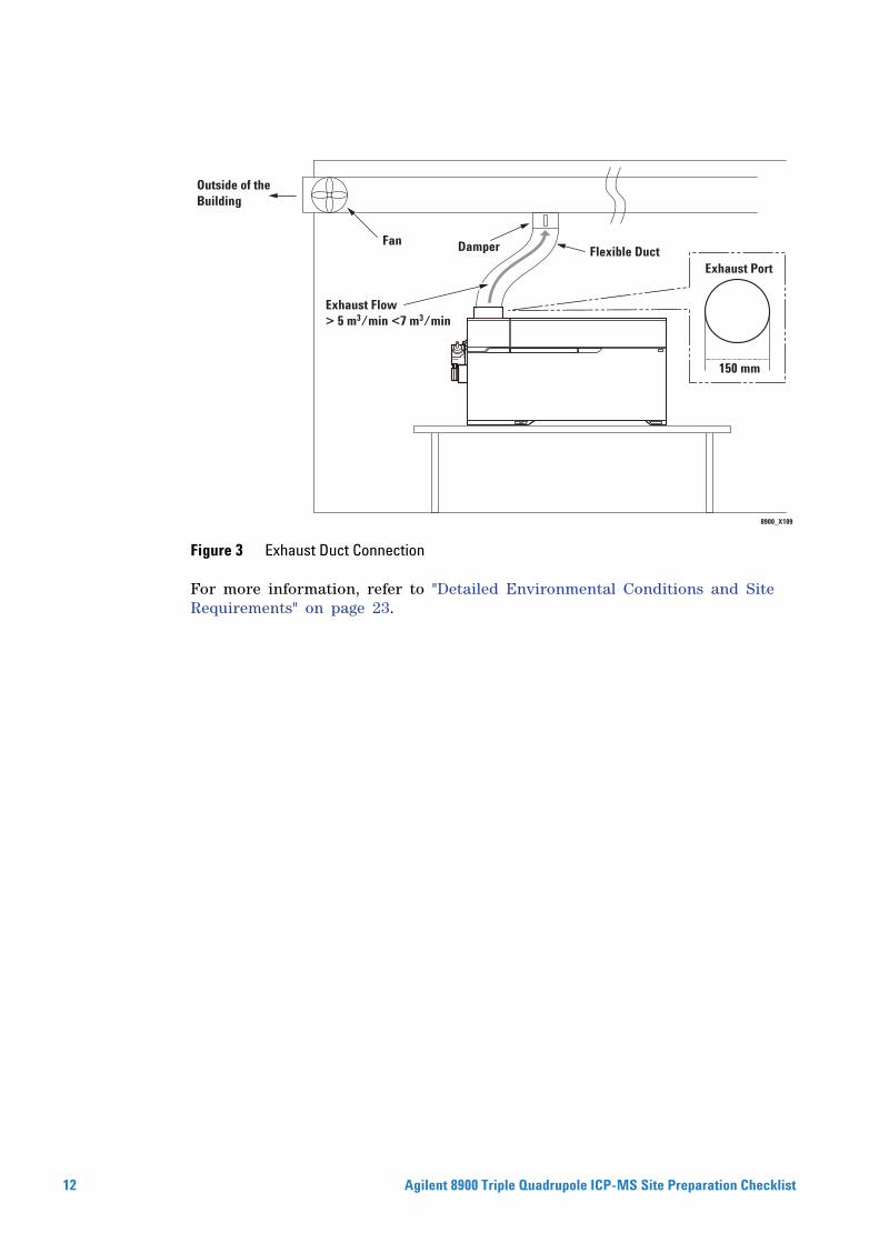
Figure 3 Exhaust Duct Connection
For more information, refer to "Detailed Environmental Conditions and Site Requirements" on page 23.
8900_X109
Outside of theBuilding
Fan Damper
Exhaust Flow> 5 m3/min <7 m3/min
Flexible DuctExhaust Port
150 mm
Agilent 8900 Triple Quadrupole ICP-MS Site Preparation Checklist
Power Consumption and Configuration
Agilent 8900 Triple Q
Special Notes
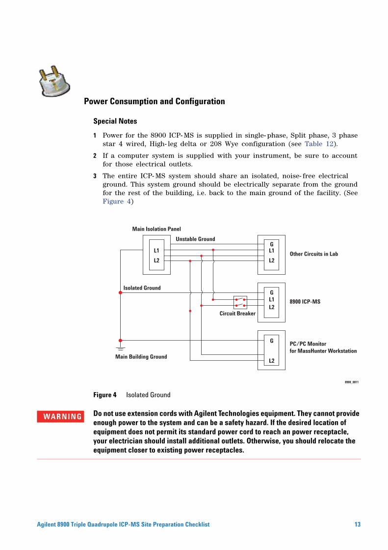
1 Power for the 8900 ICP- MS is supplied in single- phase, Split phase, 3 phase star 4 wired, High- leg delta or 208 Wye configuration (see Table 12).
2 If a computer system is supplied with your instrument, be sure to account for those electrical outlets.
3 The entire ICP- MS system should share an isolated, noise- free electrical ground. This system ground should be electrically separate from the ground for the rest of the building, i.e. back to the main ground of the facility. (See Figure 4)
Figure 4 Isolated Ground
8900_0011
Main Isolation Panel
Unstable Ground
Circuit Breaker
Other Circuits in Lab
8900 ICP-MS
PC/PC Monitorfor MassHunter Workstation
Isolated Ground
Main Building Ground
L1 L1
L2
G
L1L2
G
L2
G
L2
Do not use extension cords with Agilent Technologies equipment. They cannot provide
WARNINGenough power to the system and can be a safety hazard. If the desired location of equipment does not permit its standard power cord to reach an power receptacle, your electrician should install additional outlets. Otherwise, you should relocate the equipment closer to existing power receptacles.uadrupole ICP-MS Site Preparation Checklist 13

14
equirements
Table 6 Power RInstrument Description Line Voltage & Frequency (V, Hz)
Current Rating (amps) Maximum Power Consumption (W)
8900 ICP-MS 200 - 240 Vac, 50/60 Hz 24
PC/Monitor/Printer 100-127 Vac200-240 Vac
158
Agilent Chiller (G3292A)*1 208-230 Vac, 60 Hz240 Vac, 50 Hz
12.212.2
29002900
Agilent Chiller (G3159A)*2 200 Vac, 50/60 Hz 20
Agilent Heat Exchanger (G1879B)*3 200-240 Vac, 50 Hz100-120 Vac, 50/60 Hz
2.755.5
SPS 4 Autosampler 100-240 V, 47/63 Hz, 1.5 A input *4
0.55 55
Integrated Autosampler (I-AS) 100-120 Vac, 50/60 Hz200-240 Vac, 50/60 Hz
10.5
ASX-500 Series Autosampler 85-264 Vac <1 40
*1: The chiller will ship with the power cable for the country of installation.*2: The chiller will ship with the power cable for Japan.*3: The heat exchanger will ship with the power cable for the country of installation.*4: This is the input rating for the AC adapter. AC adapter output/autosampler input: 24 VDC, 2.5 A
Figure 5 Main Supply - Instruments Connection without Neutral
If this is not compatible with your power receptacle, it is your responsibility to connect the ICP- MS power cord safely. This can be done via an industrial standard locking plug and socket, or directly into a switched distribution panel.For more information, refer to "Detailed Power Consumption and Configuration" on page 25.
Table 7 Power Plugs and Cords
Country Supplied Plug Prepared Outlet
U.S., all Americas (North, Central and South American countries), Japan, Korea and Taiwan
NEMA L6- 30P with 4.3 m power cord NEMA L6- 30R
Others IEC 60309 with 4.3 m power cord IEC 60309
8900 0019
8900 ICP-MS
Safety Ground
1 L1
200 V L2
Power Receptacle
Circuit Breaker30 A (rating)
Power Plug
Agilent 8900 Triple Quadrupole ICP-MS Site Preparation Checklist
Cooling Water Requirements
Agilent 8900 Triple Q
Special Notes
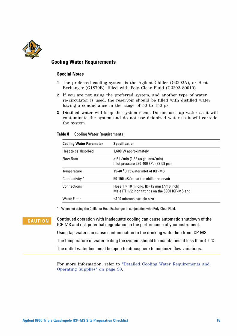
1 The preferred cooling system is the Agilent Chiller (G3292A), or Heat Exchanger (G1879B), filled with Poly- Clear Fluid (G3292- 80010).
2 If you are not using the preferred system, and another type of water re- circulator is used, the reservoir should be filled with distilled water having a conductance in the range of 50 to 150 µs.
3 Distilled water will keep the system clean. Do not use tap water as it will contaminate the system and do not use deionized water as it will corrode the system.
* When not using the Chiller or Heat Exchanger in conjunction with Poly-Clear Fluid.
Table 8 Cooling Water Requirements
Cooling Water Parameter Specification
Heat to be absorbed 1,600 W approximately
Flow Rate > 5 L/min (1.32 us gallons/min)Inlet pressure 230-400 kPa (33-58 psi)
Temperature 15-40 °C at water inlet of ICP-MS
Conductivity * 50-150 µS/cm at the chiller reservoir
Connections Hose 1 × 10 m long, ID=12 mm (7/16 inch)Male PT 1/2 inch fittings on the 8900 ICP-MS end
Water Filter <100 microns particle size
Continued operation with inadequate cooling can cause automatic shutdown of the
CAUTIONICP-MS and risk potential degradation in the performance of your instrument.Using tap water can cause contamination to the drinking water line from ICP-MS.
The temperature of water exiting the system should be maintained at less than 40 °C.
The outlet water line must be open to atmosphere to minimize flow variations.
For more information, refer to "Detailed Cooling Water Requirements and Operating Supplies" on page 30.
uadrupole ICP-MS Site Preparation Checklist 15
Gas Requirements
16
Special Notes
1 Individual stop valves must be installed for all gas lines for each individual ICP- MS instrument.
2 The Argon gas regulators should be within 5 meters of the ICP- MS. It is strongly recommended that the cell gas cylinder, regulator with pressure gauge and shutoff valve are within 3 m of the ICP- MS.
3 It is recommended to use clean gas regulators (all- metal) and EP- grade stainless steel tubes especially for ultra trace S or Si analysis.
Argon Gas
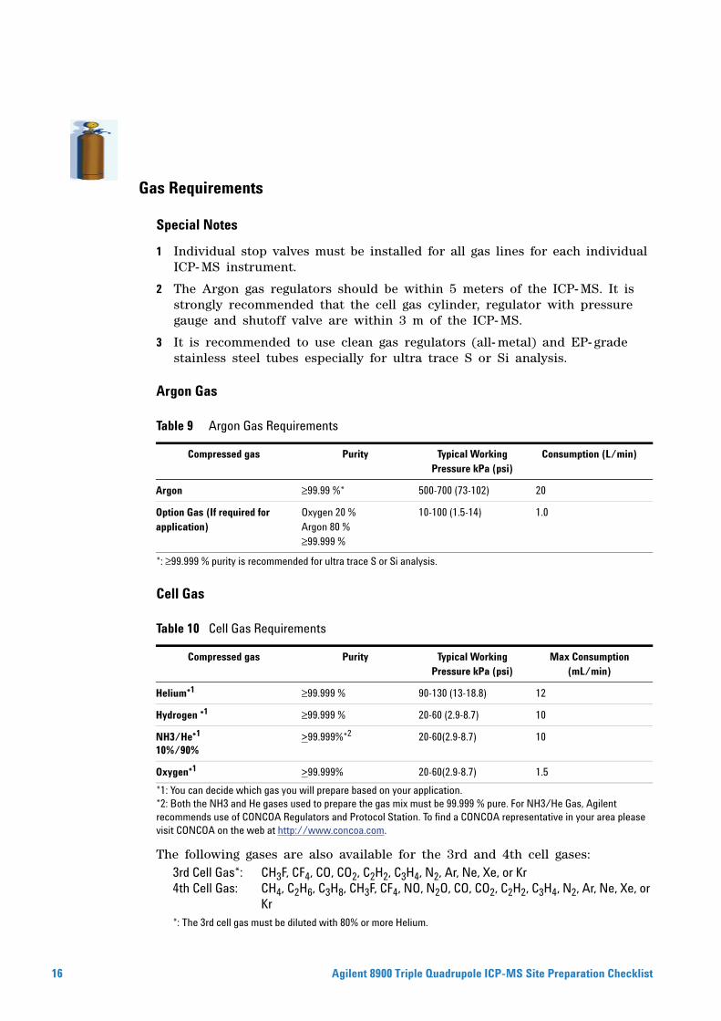
*: ≥99.999 % purity is recommended for ultra trace S or Si analysis.
Cell Gas
*1: You can decide which gas you will prepare based on your application.*2: Both the NH3 and He gases used to prepare the gas mix must be 99.999 % pure. For NH3/He Gas, Agilent recommends use of CONCOA Regulators and Protocol Station. To find a CONCOA representative in your area please visit CONCOA on the web at http://www.concoa.com.
The following gases are also available for the 3rd and 4th cell gases:
*: The 3rd cell gas must be diluted with 80% or more Helium.
Table 9 Argon Gas Requirements
Compressed gas Purity Typical Working Pressure kPa (psi)
Consumption (L/min)
Argon ≥99.99 %* 500-700 (73-102) 20
Option Gas (If required for application)
Oxygen 20 %Argon 80 %≥99.999 %
10-100 (1.5-14) 1.0
Table 10 Cell Gas Requirements
Compressed gas Purity Typical Working Pressure kPa (psi)
Max Consumption (mL/min)
Helium*1 ≥99.999 % 90-130 (13-18.8) 12
Hydrogen *1 ≥99.999 % 20-60 (2.9-8.7) 10
NH3/He*1
10%/90% >99.999%*2 20-60(2.9-8.7) 10
Oxygen*1 >99.999% 20-60(2.9-8.7) 1.5
3rd Cell Gas*: CH3F, CF4, CO, CO2, C2H2, C3H4, N2, Ar, Ne, Xe, or Kr4th Cell Gas: CH4, C2H6, C3H8, CH3F, CF4, NO, N2O, CO, CO2, C2H2, C3H4, N2, Ar, Ne, Xe, or
Kr
Agilent 8900 Triple Quadrupole ICP-MS Site Preparation Checklist
Agilent 8900 Triple Q
3rd Cell Gas:
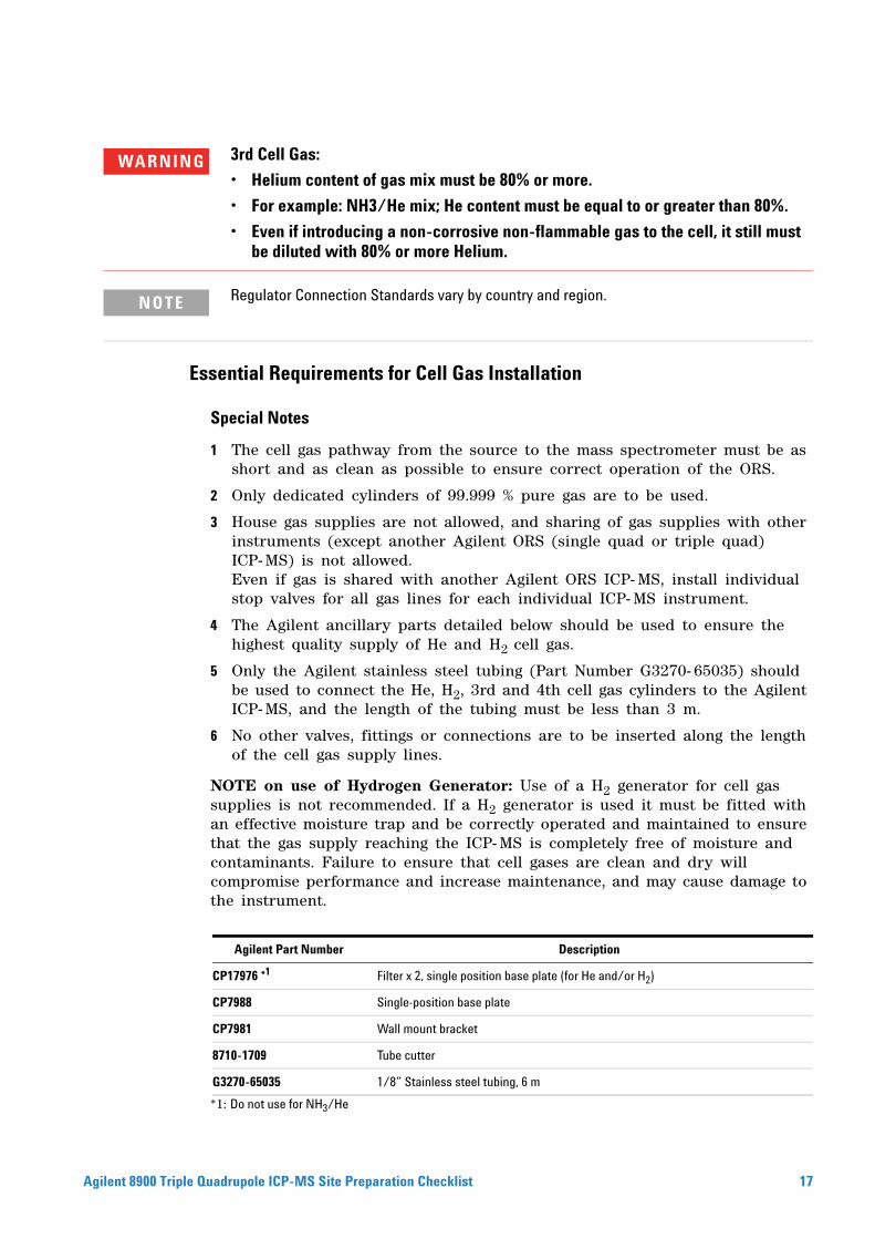
WARNING• Helium content of gas mix must be 80% or more.• For example: NH3/He mix; He content must be equal to or greater than 80%.
• Even if introducing a non-corrosive non-flammable gas to the cell, it still must be diluted with 80% or more Helium.
Regulator Connection Standards vary by country and region.
Essential Requirements for Cell Gas Installation
NOTE
Special Notes
1 The cell gas pathway from the source to the mass spectrometer must be as short and as clean as possible to ensure correct operation of the ORS.
2 Only dedicated cylinders of 99.999 % pure gas are to be used.
3 House gas supplies are not allowed, and sharing of gas supplies with other instruments (except another Agilent ORS (single quad or triple quad) ICP- MS) is not allowed.Even if gas is shared with another Agilent ORS ICP- MS, install individual stop valves for all gas lines for each individual ICP- MS instrument.
4 The Agilent ancillary parts detailed below should be used to ensure the highest quality supply of He and H2 cell gas.
5 Only the Agilent stainless steel tubing (Part Number G3270- 65035) should be used to connect the He, H2, 3rd and 4th cell gas cylinders to the Agilent ICP- MS, and the length of the tubing must be less than 3 m.
6 No other valves, fittings or connections are to be inserted along the length of the cell gas supply lines.
NOTE on use of Hydrogen Generator: Use of a H2 generator for cell gas supplies is not recommended. If a H2 generator is used it must be fitted with an effective moisture trap and be correctly operated and maintained to ensure that the gas supply reaching the ICP- MS is completely free of moisture and contaminants. Failure to ensure that cell gases are clean and dry will compromise performance and increase maintenance, and may cause damage to the instrument.
*1: Do not use for NH3/He
Agilent Part Number Description
CP17976 *1 Filter x 2, single position base plate (for He and/or H2)
CP7988 Single-position base plate
CP7981 Wall mount bracket
8710-1709 Tube cutter
G3270-65035 1/8” Stainless steel tubing, 6 m
uadrupole ICP-MS Site Preparation Checklist 17
18
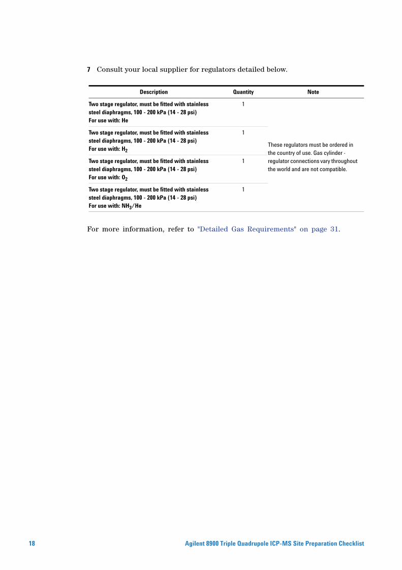
7 Consult your local supplier for regulators detailed below.
For more information, refer to "Detailed Gas Requirements" on page 31.
Description Quantity Note
Two stage regulator, must be fitted with stainless steel diaphragms, 100 - 200 kPa (14 - 28 psi)For use with: He
1
These regulators must be ordered in the country of use. Gas cylinder - regulator connections vary throughout the world and are not compatible.
Two stage regulator, must be fitted with stainless steel diaphragms, 100 - 200 kPa (14 - 28 psi)For use with: H2
1
Two stage regulator, must be fitted with stainless steel diaphragms, 100 - 200 kPa (14 - 28 psi)For use with: O2
1
Two stage regulator, must be fitted with stainless steel diaphragms, 100 - 200 kPa (14 - 28 psi)For use with: NH3/He
1
Agilent 8900 Triple Quadrupole ICP-MS Site Preparation Checklist
Communications
Agilent 8900 Triple Q
Special Notes
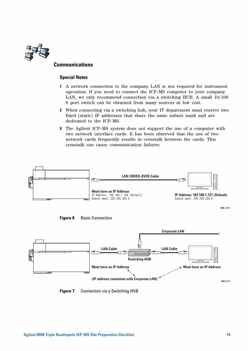
1 A network connection to the company LAN is not required for instrument operation. If you need to connect the ICP- MS computer to your company LAN, we only recommend connection via a switching HUB. A small 10/100 6 port switch can be obtained from many sources at low cost.
2 When connecting via a switching hub, your IT department must reserve two fixed (static) IP addresses that share the same subnet mask and are dedicated to the ICP- MS.
3 The Agilent ICP- MS system does not support the use of a computer with two network interface cards. It has been observed that the use of two network cards frequently results in crosstalk between the cards. This crosstalk can cause communication failures.
8900_X110
LAN CROSS-OVER Cable
Must have an IP AddressIP Address: 192.168.1.127 (Default)
Figure 6 Basic Connection
8900_X111
LAN Cable LAN Cable
Switching HUB
Corporate LAN
Must have an IP Address
(IP address consistent with Corporate LAN)
Must have an IP Address
Figure 7 Connection via a Switching HUB
uadrupole ICP-MS Site Preparation Checklist 19
Laboratory Supply Requirements
20
Special Notes
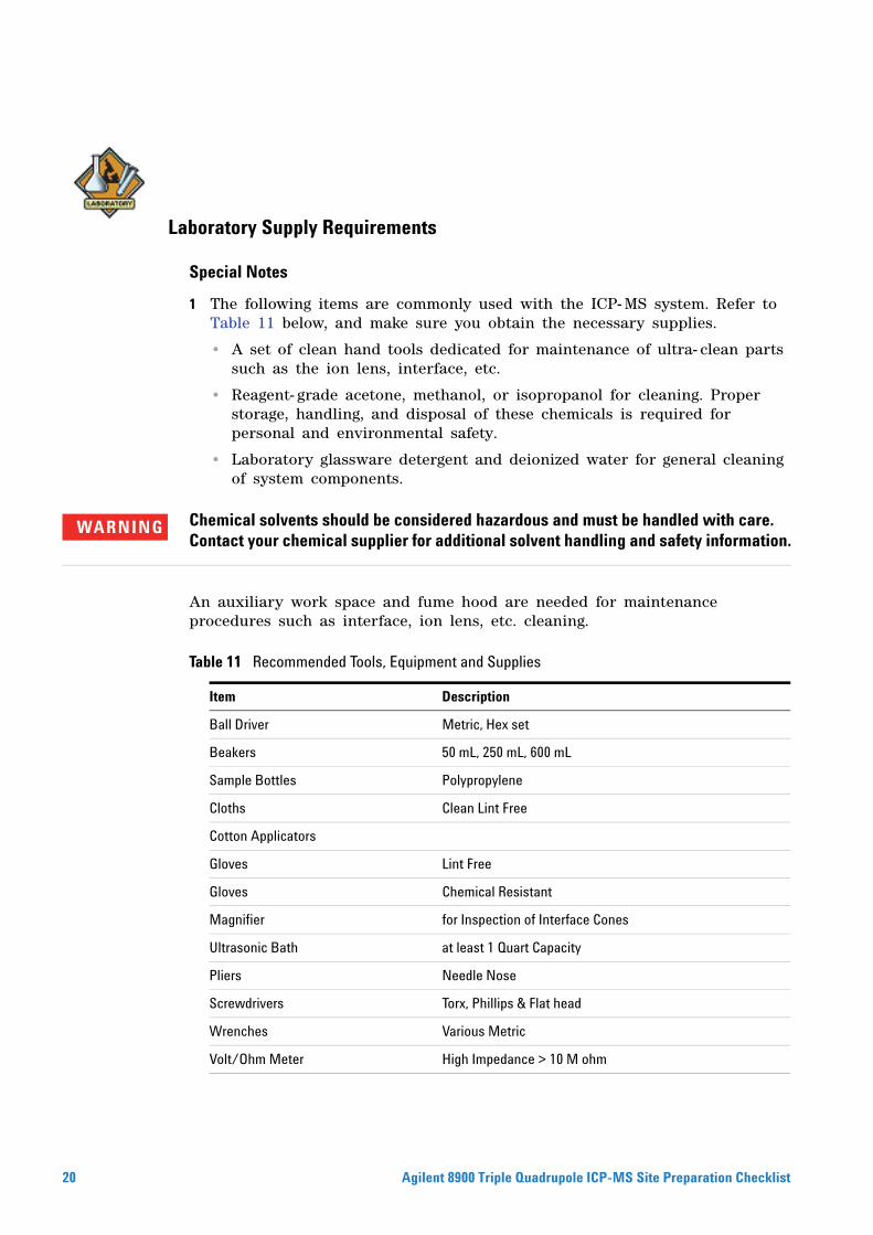
1 The following items are commonly used with the ICP- MS system. Refer to Table 11 below, and make sure you obtain the necessary supplies.
• A set of clean hand tools dedicated for maintenance of ultra- clean parts such as the ion lens, interface, etc.
• Reagent- grade acetone, methanol, or isopropanol for cleaning. Proper storage, handling, and disposal of these chemicals is required for personal and environmental safety.
• Laboratory glassware detergent and deionized water for general cleaning of system components.
Chemical solvents should be considered hazardous and must be handled with care.
WARNINGContact your chemical supplier for additional solvent handling and safety information.An auxiliary work space and fume hood are needed for maintenance procedures such as interface, ion lens, etc. cleaning.
Table 11 Recommended Tools, Equipment and Supplies
Item Description
Ball Driver Metric, Hex set
Beakers 50 mL, 250 mL, 600 mL
Sample Bottles Polypropylene
Cloths Clean Lint Free
Cotton Applicators
Gloves Lint Free
Gloves Chemical Resistant
Magnifier for Inspection of Interface Cones
Ultrasonic Bath at least 1 Quart Capacity
Pliers Needle Nose
Screwdrivers Torx, Phillips & Flat head
Wrenches Various Metric
Volt/Ohm Meter High Impedance > 10 M ohm
Agilent 8900 Triple Quadrupole ICP-MS Site Preparation Checklist
Other Requirements
Agilent 8900 Triple Q
Special Notes
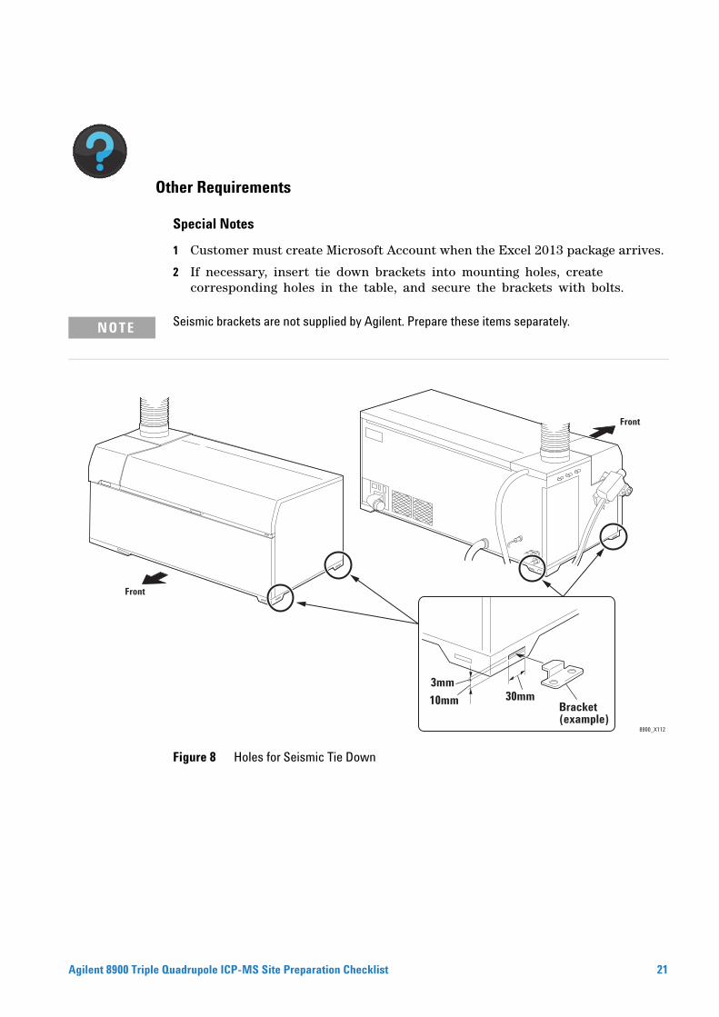
1 Customer must create Microsoft Account when the Excel 2013 package arrives.
2 If necessary, insert tie down brackets into mounting holes, create corresponding holes in the table, and secure the brackets with bolts.
Seismic brackets are not supplied by Agilent. Prepare these items separately.
NOTE8900_X112
30mm10mm
Front
3mm
Front
Bracket (example)
Figure 8 Holes for Seismic Tie Down
uadrupole ICP-MS Site Preparation Checklist 21
Important Customer Web Links
22
• For additional information about our solutions, please visit our web site at http://www.chem.agilent.com/en- US/Pages/HomePage.aspx
• Need to get information on your product?Literature Library - http://www.agilent.com/chem/library
• Need to know more?Customer Education – http://www.agilent.com/chem/education
• Need technical support, FAQs? – http://www.agilent.com/chem/techsupp
• Need supplies? – http://www.agilent.com/chem/supplies
Agilent 8900 Triple Quadrupole ICP-MS Site Preparation Checklist
Appendix
Detailed Environmental Conditions and Site Requirements
Agilent 8900 Triple Q
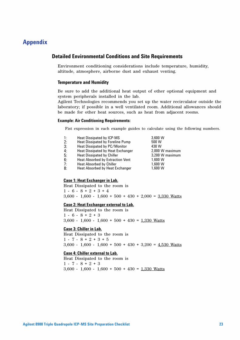
Environment conditioning considerations include temperature, humidity, altitude, atmosphere, airborne dust and exhaust venting.
Temperature and Humidity
Be sure to add the additional heat output of other optional equipment and system peripherals installed in the lab.Agilent Technologies recommends you set up the water recirculator outside the laboratory; if possible in a well ventilated room. Additional allowances should be made for other heat sources, such as heat from adjacent rooms.
Example: Air Conditioning Requirements:
Fist expression in each example guides to calculate using the following numbers.
Case 1: Heat Exchanger in Lab.Heat Dissipated to the room is1 - 6 - 8 + 2 + 3 + 43,600 - 1,600 - 1,600 + 500 + 430 + 2,000 = 3,330 Watts
Case 2: Heat Exchanger external to Lab.Heat Dissipated to the room is1 - 6 - 8 + 2 + 33,600 - 1,600 - 1,600 + 500 + 430 = 1,330 Watts
Case 3: Chiller in Lab.Heat Dissipated to the room is1 - 7 - 8 + 2 + 3 + 53,600 - 1,600 - 1,600 + 500 + 430 + 3,200 = 4,530 Watts
Case 4: Chiller external to Lab.Heat Dissipated to the room is1 - 7 - 8 + 2 + 33,600 - 1,600 - 1,600 + 500 + 430 = 1,330 Watts
1: Heat Dissipated by ICP-MS 3,600 W2: Heat Dissipated by Foreline Pump 500 W3: Heat Dissipated by PC/Monitor 430 W4: Heat Dissipated by Heat Exchanger 2,000 W maximum5: Heat Dissipated by Chiller 3,200 W maximum6: Heat Absorbed by Extraction Vent 1,600 W7: Heat Absorbed by Chiller 1,600 W8: Heat Absorbed by Heat Exchanger 1,600 W
uadrupole ICP-MS Site Preparation Checklist 23
24
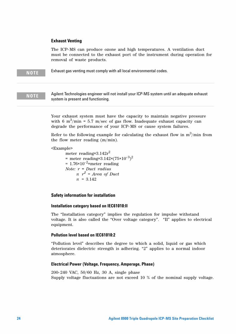
Exhaust Venting
The ICP- MS can produce ozone and high temperatures. A ventilation duct must be connected to the exhaust port of the instrument during operation for removal of waste products.
Exhaust gas venting must comply with all local environmental codes.
NOTEAgilent Technologies engineer will not install your ICP-MS system until an adequate exhaust
NOTEsystem is present and functioning.Your exhaust system must have the capacity to maintain negative pressure with 6 m3/min = 5.7 m/sec of gas flow. Inadequate exhaust capacity can degrade the performance of your ICP- MS or cause system failures.
Refer to the following example for calculating the exhaust flow in m3/min from the flow meter reading (m/min).
<Example>meter reading×3.142r2
= meter reading×3.142×(75×10- 3)2 = 1.76×10- 2×meter reading Note: r = Duct radius
r2 = Area of Duct = 3.142
Safety information for installation
Installation category based on IEC61010:II
The “Installation category” implies the regulation for impulse withstand voltage. It is also called the “Over voltage category”. “II” applies to electrical equipment.
Pollution level based on IEC61010:2
“Pollution level” describes the degree to which a solid, liquid or gas which deteriorates dielectric strength is adhering. “2” applies to a normal indoor atmosphere.
Electrical Power (Voltage, Frequency, Amperage, Phase)
200- 240 VAC, 50/60 Hz, 30 A, single phaseSupply voltage fluctuations are not exceed 10 % of the nominal supply voltage.
Agilent 8900 Triple Quadrupole ICP-MS Site Preparation Checklist
Detailed Power Consumption and Configuration
Agilent 8900 Triple Q
General Power Configuration
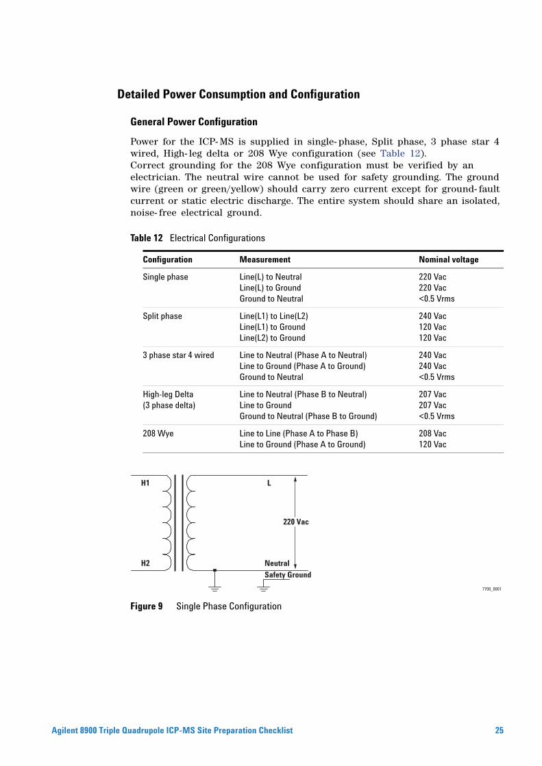
Power for the ICP- MS is supplied in single- phase, Split phase, 3 phase star 4 wired, High- leg delta or 208 Wye configuration (see Table 12).Correct grounding for the 208 Wye configuration must be verified by an electrician. The neutral wire cannot be used for safety grounding. The ground wire (green or green/yellow) should carry zero current except for ground- fault current or static electric discharge. The entire system should share an isolated, noise- free electrical ground.
Figure 9 Single Phase Configuration
Table 12 Electrical Configurations
Configuration Measurement Nominal voltage
Single phase Line(L) to NeutralLine(L) to GroundGround to Neutral
220 Vac220 Vac<0.5 Vrms
Split phase Line(L1) to Line(L2)Line(L1) to GroundLine(L2) to Ground
240 Vac120 Vac120 Vac
3 phase star 4 wired Line to Neutral (Phase A to Neutral)Line to Ground (Phase A to Ground)Ground to Neutral
240 Vac240 Vac<0.5 Vrms
High-leg Delta(3 phase delta)
Line to Neutral (Phase B to Neutral)Line to GroundGround to Neutral (Phase B to Ground)
207 Vac207 Vac<0.5 Vrms
208 Wye Line to Line (Phase A to Phase B)Line to Ground (Phase A to Ground)
208 Vac120 Vac
7700_0001
LH1
H2
Safety Ground
Neutral
220 Vac
uadrupole ICP-MS Site Preparation Checklist 25
26
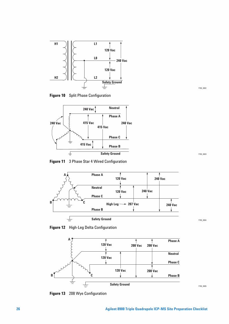
Figure 10 Split Phase Configuration
Figure 11 3 Phase Star 4 Wired Configuration
Figure 12 High-Leg Delta Configuration
Figure 13 208 Wye Configuration
7700_0002
H1
H2
L1
L0
L2
240 Vac
120 Vac
120 Vac
Safety Ground
7700_0003
240 Vac 415 Vac
415 Vac
240 Vac
415 Vac240 Vac
Phase A
Neutral
Phase C
Phase B
Safety Ground
7700_0004
120 Vac
120 Vac
High Leg 240 Vac
240 Vac
240 Vac
207 Vac
Phase A
Neutral
Phase C
C
A
B
Phase B
Safety Ground
7700_0005
208 Vac208 Vac120 Vac
208 Vac
120 Vac
120 VacC
A
B
Phase A
Neutral
Phase C
Phase B
Safety Ground
Agilent 8900 Triple Quadrupole ICP-MS Site Preparation Checklist
Agilent 8900 Triple Q
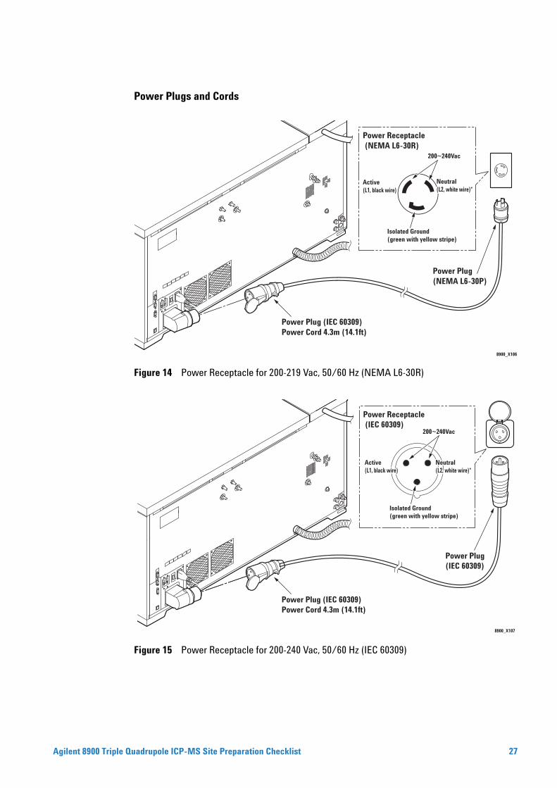
Power Plugs and Cords
Figure 14 Power Receptacle for 200-219 Vac, 50/60 Hz (NEMA L6-30R)
Figure 15 Power Receptacle for 200-240 Vac, 50/60 Hz (IEC 60309)
8900_X106
Power Plug (IEC 60309)Power Cord 4.3m (14.1ft)
Power Plug (NEMA L6-30P)
Neutral Neutral (L2, white wire)*(L2, white wire)*
200~240Vac
Power Receptacle (NEMA L6-30R)
Isolated Ground(green with yellow stripe)
Active(L1, black wire)
Neutral (L2, white wire)*
8900_X107
Power Plug (IEC 60309)Power Cord 4.3m (14.1ft)
Power Plug (IEC 60309)
Neutral Neutral (L2, white wire)*(L2, white wire)*
200~240Vac
Isolated Ground(green with yellow stripe)
ActiveActive(L1, black wire)(L1, black wire)Active(L1, black wire)
Neutral (L2, white wire)*
Power Receptacle (IEC 60309)
uadrupole ICP-MS Site Preparation Checklist 27
28
Power Conditioner/Uninterruptible Power Supply (UPS)
If the power supplied is outside the limits specified, a power conditioner may be required. Power conditioners aid in filtering impulses caused by lightning strikes, line spikes, oscillatory transients and electrical noise impulses.
It is the customer’s responsibility to install the power conditioner and supply any additional equipment, circuit breakers, switches, etc., before the Agilent Technologies engineer arrives on site.
It is your responsibility to comply with all local and national electrical and safety codes. Check with your electrical department!
Data system components and accessories have power cords with plugs depending on the voltage and power cord option ordered. Power cord lengths for the data system components and accessories are 2.5 m.
The ICP-MS has a start up rush current of 150 A for 15 milliseconds.
NOTEAgilent 8900 Triple Quadrupole ICP-MS Site Preparation Checklist
Agilent 8900 Triple Q
General Power Requirements
Table 6 lists the power requirements for the ICP- MS and associated equipment. Extra power capacity for the future growth of your laboratory should be considered now. Power requirements and considerations include the following.
Each product listed in Table 6 requires a dedicated circuit. The ICP- MS mainframe, PC/PC monitor, water recirculator, etc. should each have a separate circuit breaker.
Power must meet the stability and transient specifications listed in Table 6. We recommend your site power specialist use a line monitor to check power stability. If your line power is unstable, you may need to install a line conditioner.
Separate convenience outlets should be provided for building maintenance and other appliances. Convenience outlets must be on circuits separate from the ICP- MS system and must share the normal building distribution ground, not the ICP- MS system ground.
In some geographical areas it may be advisable to install lightning protection for personnel and equipment.
Electromagnetic interference (EMI) generated by NMRs, radio transmitters, and microwave links, may interfere with system performance. Protect the system from static electricity by observing humidity and temperature requirements. Minimize the presence of non- conductive products such as carpets and vinyl floor tiles.
Emergency- off push buttons that will disconnect power to the ventilation system and all electric equipment in the room except overhead lighting are recommended.
A minimum of 4 power receptacles are required for data system installation; 6 power receptacles are recommended. Surge protection on the data system circuit is also recommended.
There is a power receptacle on the rear of the ICP-MS, it is dedicated for the Foreline
CAUTIONPump. DO NOT USE FOR ANY OTHER AUXILIARY EQUIPMENT.1 Verify that the voltage available on site is adequate for all the equipment ordered.
NOTE2 Approximate values. Refer to the specific product specification. Data systems typicallyrequire at least 4 outlets and a 15 A circuit with surge suppression.
uadrupole ICP-MS Site Preparation Checklist 29
Detailed Cooling Water Requirements and Operating Supplies
30
Water Quality
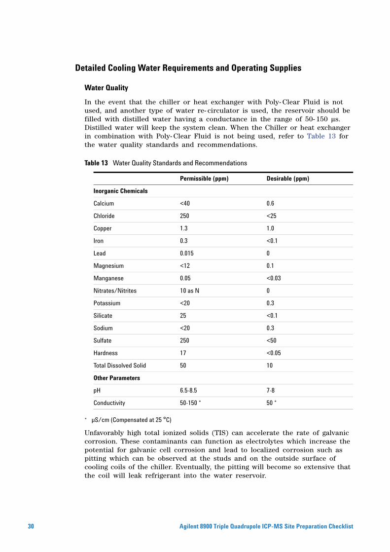
In the event that the chiller or heat exchanger with Poly- Clear Fluid is not used, and another type of water re- circulator is used, the reservoir should be filled with distilled water having a conductance in the range of 50- 150 µs. Distilled water will keep the system clean. When the Chiller or heat exchanger in combination with Poly- Clear Fluid is not being used, refer to Table 13 for the water quality standards and recommendations.
* µS/cm (Compensated at 25 °C)
Unfavorably high total ionized solids (TIS) can accelerate the rate of galvanic corrosion. These contaminants can function as electrolytes which increase the potential for galvanic cell corrosion and lead to localized corrosion such as pitting which can be observed at the studs and on the outside surface of cooling coils of the chiller. Eventually, the pitting will become so extensive that the coil will leak refrigerant into the water reservoir.
Table 13 Water Quality Standards and Recommendations
Permissible (ppm) Desirable (ppm)
Inorganic Chemicals
Calcium <40 0.6
Chloride 250 <25
Copper 1.3 1.0
Iron 0.3 <0.1
Lead 0.015 0
Magnesium <12 0.1
Manganese 0.05 <0.03
Nitrates/Nitrites 10 as N 0
Potassium <20 0.3
Silicate 25 <0.1
Sodium <20 0.3
Sulfate 250 <50
Hardness 17 <0.05
Total Dissolved Solid 50 10
Other Parameters
pH 6.5-8.5 7-8
Conductivity 50-150 * 50 *
Agilent 8900 Triple Quadrupole ICP-MS Site Preparation Checklist
Agilent 8900 Triple Q
As an example, raw water in the United States averages 171 ppm (of NaCl). The recommended level for use in a water system is between 0.5 to 5.0 ppm (of NaCl).
Initially fill the tank with distilled water. Do not use tap water as the total ionized solids level may
Detailed Gas Requirements
NOTEbe too high.
Do not use deionized water as it will corrode the system.
The Argon gas needed for installation will be supplied by the customer.
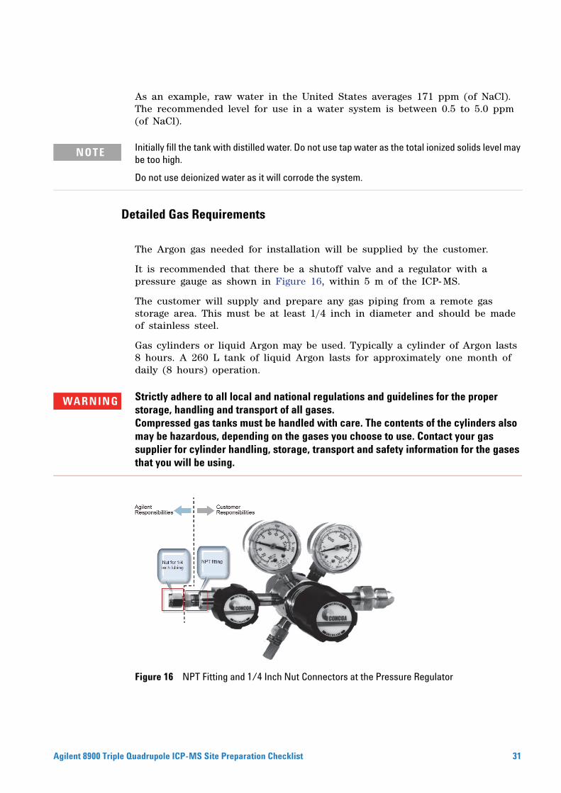
It is recommended that there be a shutoff valve and a regulator with a pressure gauge as shown in Figure 16, within 5 m of the ICP- MS.
The customer will supply and prepare any gas piping from a remote gas storage area. This must be at least 1/4 inch in diameter and should be made of stainless steel.
Gas cylinders or liquid Argon may be used. Typically a cylinder of Argon lasts 8 hours. A 260 L tank of liquid Argon lasts for approximately one month of daily (8 hours) operation.
Strictly adhere to all local and national regulations and guidelines for the proper
WARNINGstorage, handling and transport of all gases.Compressed gas tanks must be handled with care. The contents of the cylinders also may be hazardous, depending on the gases you choose to use. Contact your gas supplier for cylinder handling, storage, transport and safety information for the gases that you will be using.Figure 16 NPT Fitting and 1/4 Inch Nut Connectors at the Pressure Regulator
uadrupole ICP-MS Site Preparation Checklist 31
32
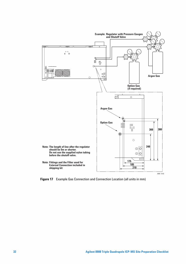
Figure 17 Example Gas Connection and Connection Location (all units in mm)
8900_X103
Option Gas(if required)
Note: The length of line after the regulator should be 5m or shorter. Do not use the supplied nylon tubing before the shutoff valve.
Note: Fittings and the Filter used for External Connection included in shipping kit
Option Gas
Argon Gas
Example: Regulator with Pressure Gauges and Shutoff Valve
Argon Gas
380
240
210185
360
175
Agilent 8900 Triple Quadrupole ICP-MS Site Preparation Checklist
Agilent 8900 Triple Q
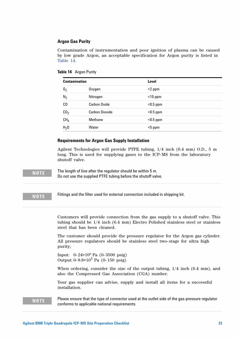
Argon Gas Purity
Contamination of instrumentation and poor ignition of plasma can be caused by low grade Argon, an acceptable specification for Argon purity is listed in Table 14.
Requirements for Argon Gas Supply Installation
Agilent Technologies will provide PTFE tubing, 1/4 inch (6.4 mm) O.D., 5 m long. This is used for supplying gases to the ICP- MS from the laboratory shutoff valve.
Table 14 Argon Purity
Contamination Level
O2 Oxygen <2 ppm
N2 Nitrogen <10 ppm
CO Carbon Oxide <0.5 ppm
CO2 Carbon Dioxide <0.5 ppm
CH4 Methane <0.5 ppm
H2O Water <5 ppm
The length of line after the regulator should be within 5 m.
NOTEDo not use the supplied PTFE tubing before the shutoff valve.Fittings and the filter used for external connection included in shipping kit.
NOTECustomers will provide connection from the gas supply to a shutoff valve. This tubing should be 1/4 inch (6.4 mm) Electro Polished stainless steel or stainless steel that has been cleaned.
The customer should provide the pressure regulator for the Argon gas cylinder. All pressure regulators should be stainless steel two- stage for ultra high purity;
Input: 0- 24×106 Pa (0- 3500 psig)Output: 0- 9.8×10⁵ Pa (0- 150 psig)
When ordering, consider the size of the output tubing, 1/4 inch (6.4 mm), and also the Compressed Gas Association (CGA) number.
Your gas supplier can advise, supply and install all items for a successful installation.
Please ensure that the type of connector used at the outlet side of the gas-pressure regulator
NOTEconforms to applicable national requirements.uadrupole ICP-MS Site Preparation Checklist 33
34
Compressed gas tanks must be handled with care. The contents of the cylinders also
WARNINGmay be hazardous depending on the gases you choose to use. Please contact your gas supplier for cylinder handling and safety information for the gases that you will be using.Cell Gas Requirement
Flammable gas (e.g. Hydrogen) and combustion-supporting gas (e.g. Oxygen) must
WARNINGalways be placed in separate safety cabinet. Fully and strictly adhere to all local and national regulations and guidelines for the proper storage, handling and transport of all gases. Consult the cylinder, regulator and/or gas supplier for additional safety measures and ensure all staff are fully familiarized with all safety precautions.Compressed gas tanks must be handled with care. The contents of the cylinders also
WARNINGmay be hazardous, depending on the gases you choose to use. Contact your gas supplier for cylinder handling, storage, transport and safety information for the gases that you will be using.Oxygen has the following properties. Handle with care.
WARNING• Oxygen supports combustion of other materials. Materials which arenoncombustible in air may become combustible in oxygen.
• When compared to being in air, the flammability range of materials increases in oxygen, and materials burn at lower temperatures.
• Open the oxygen cylinder valve slowly. Opening the valve too quickly can generate heat by adiabatic compression (a momentary high-temperature state caused by rapid compression of oxygen) and friction, increasing the risk of ignition.
• In high-density oxygen, there is a potential risk that materials such as metals (and metal powders), dust, and hydrocarbons (petroleum, greases, oils and fats, skin oils, and so on) can easily burn.
Smoking, open flames and other sources of ignition are prohibited in or near a facility
WARNINGwhich uses oxygen. Additionally, do not place inflammable and pyrophoric materials in the area. Make sure to observe all applicable local and national regulations and guidelines for the use and handling of oxygen.Agilent 8900 Triple Quadrupole ICP-MS Site Preparation Checklist
Agilent 8900 Triple Q
Health hazards of oxygen:
WARNINGThe primary health hazard at atmospheric pressure is respiratory system irritation after exposure to high oxygen concentrations. Oxygen levels in air should be maintained above 19.5% and below 23.5%. Up to 50% oxygen can be breathed for more than 24 hours without adverse effects.Prolonged exposure to high oxygen levels (>75%) can cause central nervous system depression: signs/symptoms can include headache, dizziness, drowsiness, poor coordination, slowed reaction time, slurred speech, giddiness and unconsciousness. In addition, note the following inhalation effects from acute exposure: may cause breathing difficulty; may cause coughing and chest pain; may cause lung damage; may cause soreness of the throat.
It is strongly recommended that the cell gas cylinder, regulator with pressure gauge and shutoff valve are within 3 m of the ICP- MS.
The ICP- MS will be shipped with 1/8 inch Swagelok® fitting for Helium, Hydrogen, 3rd and 4th cell gas connections on the rear of the instrument.
uadrupole ICP-MS Site Preparation Checklist 35
36
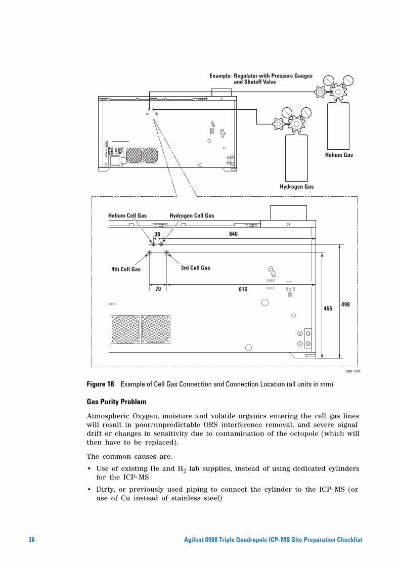
Figure 18 Example of Cell Gas Connection and Connection Location (all units in mm)
Gas Purity Problem
Atmospheric Oxygen, moisture and volatile organics entering the cell gas lines will result in poor/unpredictable ORS interference removal, and severe signal drift or changes in sensitivity due to contamination of the octopole (which will then have to be replaced).
The common causes are:
• Use of existing He and H2 lab supplies, instead of using dedicated cylinders for the ICP- MS
• Dirty, or previously used piping to connect the cylinder to the ICP- MS (or use of Cu instead of stainless steel)
8900_X104
Hydrogen Gas
Example: Regulator with Pressure Gauges and Shutoff Valve
Helium Gas
Helium Cell Gas Hydrogen Cell Gas
4th Cell Gas 3rd Cell Gas
455
61570
64030
490
Agilent 8900 Triple Quadrupole ICP-MS Site Preparation Checklist
Agilent 8900 Triple Q
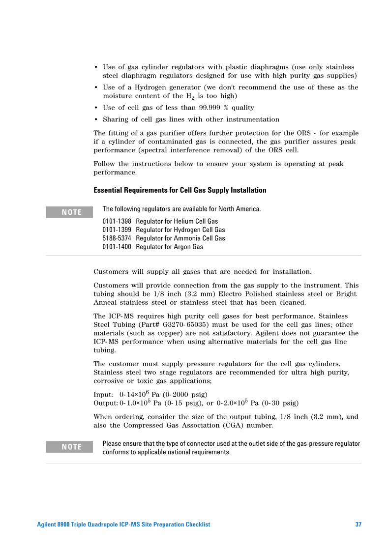
• Use of gas cylinder regulators with plastic diaphragms (use only stainless steel diaphragm regulators designed for use with high purity gas supplies)
• Use of a Hydrogen generator (we don't recommend the use of these as the moisture content of the H2 is too high)
• Use of cell gas of less than 99.999 % quality
• Sharing of cell gas lines with other instrumentation
The fitting of a gas purifier offers further protection for the ORS - for example if a cylinder of contaminated gas is connected, the gas purifier assures peak performance (spectral interference removal) of the ORS cell.
Follow the instructions below to ensure your system is operating at peak performance.
Essential Requirements for Cell Gas Supply Installation
The following regulators are available for North America.
NOTE0101-1398 Regulator for Helium Cell Gas0101-1399 Regulator for Hydrogen Cell Gas5188-5374 Regulator for Ammonia Cell Gas0101-1400 Regulator for Argon GasCustomers will supply all gases that are needed for installation.
Customers will provide connection from the gas supply to the instrument. This tubing should be 1/8 inch (3.2 mm) Electro Polished stainless steel or Bright Anneal stainless steel or stainless steel that has been cleaned.
The ICP- MS requires high purity cell gases for best performance. Stainless Steel Tubing (Part# G3270- 65035) must be used for the cell gas lines; other materials (such as copper) are not satisfactory. Agilent does not guarantee the ICP- MS performance when using alternative materials for the cell gas line tubing.
The customer must supply pressure regulators for the cell gas cylinders. Stainless steel two stage regulators are recommended for ultra high purity, corrosive or toxic gas applications;
Input: 0- 14×106 Pa (0- 2000 psig)Output: 0- 1.0×10⁵ Pa (0- 15 psig), or 0- 2.0×10⁵ Pa (0- 30 psig)
When ordering, consider the size of the output tubing, 1/8 inch (3.2 mm), and also the Compressed Gas Association (CGA) number.
Please ensure that the type of connector used at the outlet side of the gas-pressure regulator
NOTEconforms to applicable national requirements.uadrupole ICP-MS Site Preparation Checklist 37

38
This page is intentionally left blank.
Agilent 8900 Triple Quadrupole ICP-MS Site Preparation Checklist

www.agilent.com
In this Book
This manual will help you prepare your facility for the arrival of your new Agilent 8900 Triple Quadrupole Inductively Coupled Plasma Mass Spectrometer (ICP- MS). The specifications in this manual ensure consistent, reliable and safe installation of your ICP- MS system.
© Agilent Technologies, Inc. 2016
Revision A, May 2016
*G3666-90020*G3666-90020
Agilent Technologies