Embed Size (px)
Citation preview
Agilent 83430ALightwave TransmitterUser’s Guide
ii
© Copyright 2000Agilent Technologies All Rights Reserved. Repro-duction, adaptation, or trans-lation without prior written permission is prohibited, except as allowed under copy-right laws.
Agilent Part No. 83430-90011Printed in USAFebruary 2000
Agilent Technologies Lightwave Division1400 Fountaingrove ParkwaySanta Rosa, CA 95403-1799, USA(707) 577-1400
Notice.The information contained in this document is subject to change without notice. Com-panies, names, and data used in examples herein are ficti-tious unless otherwise noted. Agilent Technologies makes no warranty of any kind with regard to this material, includ-ing but not limited to, the implied warranties of mer-chantability and fitness for a particular purpose. Agilent Technologies shall not be lia-ble for errors contained herein or for incidental or conse-quential damages in connec-tion with the furnishing, performance, or use of this material.
Restricted Rights Legend.Use, duplication, or disclo-sure by the U.S. Government is subject to restrictions as set forth in subparagraph (c) (1) (ii) of the Rights in Technical Data and Computer Software clause at DFARS 252.227-7013 for DOD agencies, and sub-paragraphs (c) (1) and (c) (2) of the Commercial Computer Software Restricted Rights clause at FAR 52.227-19 for other agencies.
Warranty.This Agilent Technologies instrument product is war-ranted against defects in
material and workmanship for a period of one year from date of shipment. During the war-ranty period, Agilent Technol-ogies will, at its option, either repair or replace products which prove to be defective. For warranty service or repair, this product must be returned to a service facility desig-nated by Agilent Technolo-gies. Buyer shall prepay shipping charges to Agilent Technologies and Agilent Technologies shall pay ship-ping charges to return the product to Buyer. However, Buyer shall pay all shipping charges, duties, and taxes for products returned to Agilent Technologies from another country.
Agilent Technologies war-rants that its software and firmware designated by Agi-lent Technologies for use with an instrument will execute its programming instructions when properly installed on that instrument. Agilent Tech-nologies does not warrant that the operation of the instru-ment, or software, or firmware will be uninterrupted or error-free.
Limitation of Warranty.The foregoing warranty shall not apply to defects resulting from improper or inadequate maintenance by Buyer, Buyer-supplied software or interfac-ing, unauthorized modifica-tion or misuse, operation outside of the environmental specifications for the product, or improper site preparation or maintenance.
No other warranty is expressed or implied. Agilent Technologies specifically dis-claims the implied warranties of merchantability and fitness for a particular purpose.
Exclusive Remedies.The remedies provided herein are buyer's sole and exclusive remedies. Agilent Technolo-
gies shall not be liable for any direct, indirect, special, inci-dental, or consequential dam-ages, whether based on contract, tort, or any other legal theory.
Safety Symbols.CAUTION
The caution sign denotes a hazard. It calls attention to a procedure which, if not cor-rectly performed or adhered to, could result in damage to or destruction of the product. Do not proceed beyond a cau-tion sign until the indicated conditions are fully under-stood and met.
WARNING
The warning sign denotes a hazard. It calls attention to a procedure which, if not cor-rectly performed or adhered to, could result in injury or loss of life. Do not proceed beyond a warning sign until the indicated conditions are fully understood and met.
The instruction man-ual symbol. The prod-uct is marked with this warning symbol when it is necessary for the user to refer to the instructions in the manual.
The laser radiation symbol. This warning symbol is marked on products which have a laser output.
The AC symbol is used to indicate the required nature of the line module input power.
| The ON symbols are used to mark the posi-tions of the instrument power line switch.
The OFF symbols are used to mark the positions of the instru-ment power line switch.
The CE mark is a reg-istered trademark of the European Commu-nity.
The CSA mark is a reg-istered trademark of the Canadian Stan-dards Association.
The C-Tick mark is a registered trademark of the Australian Spec-trum Management Agency.
This text denotes the instrument is an Industrial Scientific and Medical Group 1 Class A product.
Typographical Conven-
tions.
The following conventions are used in this book:
Key type for keys or text located on the keyboard or instrument.
Softkey type for key names that are displayed on the instru-ment’s screen.
Display type for words or characters displayed on the computer’s screen or instru-ment’s display.
User type for words or charac-ters that you type or enter.
Emphasis type for words or characters that emphasize some point or that are used as place holders for text that you type.
ISM1-A
The Agilent 83430A—At a Glance
The Agilent 83430A—At a Glance
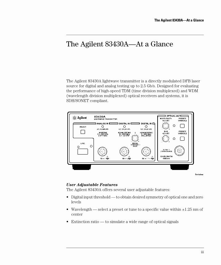
The Agilent 83430A lightwave transmitter is a directly modulated DFB laser source for digital and analog testing up to 2.5 Gb/s. Designed for evaluating the performance of high-speed TDM (time division multiplexed) and WDM (wavelength division multiplexed) optical receivers and systems, it is SDH/SONET compliant.
User Adjustable Features
The Agilent 83430A offers several user adjustable features:
• Digital input threshold — to obtain desired symmetry of optical one and zero levels
• Wavelength — select a preset or tune to a specific value within ±1.25 nm of center
• Extinction ratio — to simulate a wide range of optical signals
iii
The Agilent 83430A—At a Glance
Test Capabilities in Systems
The Agilent 83430A can be used as a general optical source or combined with other instrumentation in systems to make a variety of measurements.
• Optical parametric tests — optical receiver sensitivity, dispersion power penalty of single-mode fiber (with an Agilent 71603A error performance an-alyzer and Agilent 83446A lightwave clock/data receiver).
• Transceiver waveform testing — including filtered conformance mask test-ing, extinction ratio, and eye diagram measurements (with an Agilent 83480A digital communications analyzer).
• Jitter tolerance of recovered clock and data — to determine the ability of a receiver to maintain communication in the presence of jitter (with an Agilent 71501C jitter and eye-diagram analyzer).
• Performance testing for WDM optical MUX/DEMUX channels — including BER and system variations caused by cross-phase modulation and Raman effect (with an Agilent 83446A lightwave clock/data receiver, Agilent 71603B error performance analyzer, and Agilent 86120B multi-wavelength meter).
For setup and procedures for these and other measurements, see Chapter 2, “Making Measurements”.
Measurement accuracy—it’s up to you!
Fiber-optic connectors are easily damaged when connected to dirty or damaged cables and accessories. The Agilent 83430A’s front-panel OPTICAL OUT connector is no excep-tion. When you use improper cleaning and handling techniques, you risk expensive instrument repairs, damaged cables, and compromised measurements.
Before you connect any fiber-optic cable to the Agilent 83430A, refer to “Cleaning Con-nections for Accurate Measurements” on page 2-9.
iv
The Agilent 83430A—At a Glance
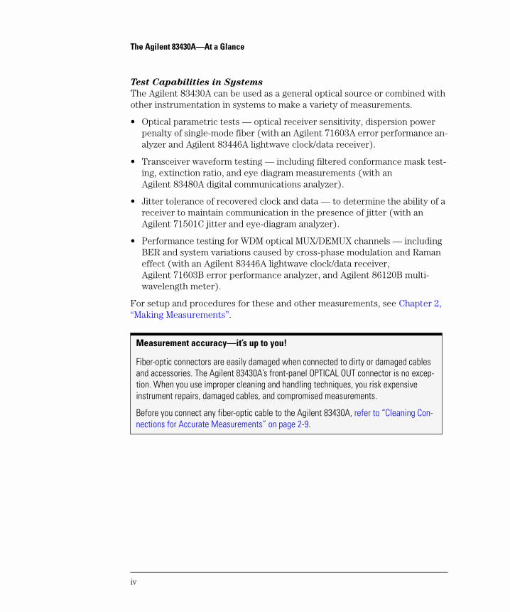
Laser classification
The Agilent 83430A is classified as an IEC LASER Class 1. The total power of light energy radiated out of the OPTICAL OUT connector is no greater than +8.1 dBm (6.5 mW). Operator maintenance or precautions are not necessary to maintain safety. No operator accessible controls, adjustments, or performance of procedures result in haz-ardous radiation exposure.
v
General Safety Considerations
General Safety Considerations
This product has been designed and tested in accordance with IEC Publica-tion 61010-1, Safety Requirements for Electrical Equipment for Measurement, Control and Laboratory Use, and has been supplied in a safe condition. The instruction documentation contains information and warnings that must be followed by the user to ensure safe operation and to maintain the product in a safe condition.
W A R N I N G If this instrument is not used as specified, the protection provided by
the equipment could be impaired. This instrument must be used in a
normal condition (in which all means for protection are intact) only.
W A R N I N G To prevent electrical shock, disconnect the Agilent 83430A from
mains before cleaning. Use a dry cloth or one slightly dampened with
water to clean the external case parts. Do not attempt to clean
internally.
W A R N I N G This is a Safety Class 1 product (provided with a protective earthing
ground incorporated in the power cord). The mains plug shall only be
inserted in a socket outlet provided with a protective earth contact.
Any interruption of the protective conductor inside or outside of the
product is likely to make the product dangerous. Intentional
interruption is prohibited.
W A R N I N G No operator serviceable parts inside. Refer servicing to qualified
personnel. To prevent electrical shock, do not remove covers.
W A R N I N G For continued protection against fire hazard, replace line fuse only
with same type and ratings, (type T 0.315A/250V for 100/120V
operation and 0.16A/250V for 220/240V operation). The use of other
fuses or materials is prohibited. Verify that the value of the line-
voltage fuse is correct.
• For 100/120V operation, use an IEC 127 5×20 mm, 0.315 A, 250 V, Agilent part number 2110-0449.
• For 220/240V operation, use an IEC 127 5×20 mm, 0.16 A, 250 V, Agilent Technologies part number 2110-0448.
vi
General Safety Considerations
C A U T I O N Before switching on this instrument, make sure that the line voltage selector switch is set to the line voltage of the power supply and the correct fuse is installed. Assure the supply voltage is in the specified range.
C A U T I O N This product is designed for use in Installation Category II and Pollution Degree 2 per IEC 1010 and 664 respectively.
C A U T I O N VENTILATION REQUIREMENTS: When installing the product in a cabinet, the convection into and out of the product must not be restricted. The ambient temperature (outside the cabinet) must be less than the maximum operating temperature of the product by 4°C for every 100 watts dissipated in the cabinet. If the total power dissipated in the cabinet is greater than 800 watts, then forced convection must be used.
C A U T I O N Always use the three-prong ac power cord supplied with this instrument. Failure to ensure adequate earth grounding by not using this cord may cause instrument damage.
C A U T I O N Do not connect ac power until you have verified the line voltage is correct, refer to “Line Power Requirements” on page 1-8. Damage to the equipment could result.
C A U T I O N This instrument has autoranging line voltage input. Be sure the supply voltage is within the specified range.
vii

Contents
The Agilent 83430A—At a Glance iii
1 Getting Started
Step 1. Inspect the Shipment 1-4Step 2. Check the Fuse 1-6Step 3. Connect the Line-Power Cable 1-8Step 4. Turn on the Agilent 83430A 1-10Returning the Instrument for Service 1-11
2 Making Measurements
Using the Agilent 83430A 2-3Cleaning Connections for Accurate Measurements 2-9
3 Specifications and Regulatory Information
Specifications 3-3Regulatory Information 3-6
4 Reference
Options 4-2Front-Panel Fiber-Optic Adapters 4-4Power Cords 4-5Agilent Technologies Service Offices 4-6
5 Servicing
General Information 5-4Electrostatic Discharge Information 5-7Troubleshooting 5-9Performance Tests 5-13Adjustment Procedures 5-36
Contents-1

1
Step 1. Inspect the Shipment 1-4Step 2. Check the Fuse 1-6Step 3. Connect the Line-Power Cable 1-8Step 4. Turn on the Agilent 83430A 1-10Returning the Instrument for Service 1-11
Getting Started
Getting StartedGetting Started
Getting Started
The instructions in this chapter show you how to install your Agilent 83430A. You should be able to finish these procedures in about ten to twenty minutes. After you’ve completed this chapter, continue with Chapter 2, “Making Mea-surements”. Refer to Chapter 3, “Specifications and Regulatory Information” for information on operating conditions such as temperature.
W A R N I N G To prevent electric shock, disconnect the Agilent 83430A from mains
before cleaning. Use a dry cloth or one slightly dampened with water
to clean the external case parts. Do not attempt to clean internally.
W A R N I N G This is a Safety Class 1 product (provided with a protective earthing
ground incorporated in the power cord). The mains plug shall only be
inserted in a socket outlet provided with a protective earth contact.
Any interruption of the protective conductor inside or outside of the
product is likely to make the product dangerous. Intentional
interruption is prohibited.
C A U T I O N This product has autoranging line voltage input. Be sure the supply voltage is within the specified range.
C A U T I O N VENTILATION REQUIREMENTS: When installing the product in a cabinet, the convection into and out of the product must not be restricted. The ambient temperature (outside the cabinet) must be less than the maximum operating temperature of the product by 4°C for every 100 watts dissipated in the cabinet. If the total power dissipated in the cabinet is greater than 800 watts, then forced convection must be used.
C A U T I O N This product is designed for use in INSTALLATION CATEGORY II and POLLUTION DEGREE 2, per IEC 1010 and 664 respectively.
C A U T I O N Before switching on this instrument, make sure that the line voltage selector switch is set to the line voltage of the power supply and the correct fuse is installed. Assure the supply voltage is in the specified range.
1-2
Getting StartedGetting Started
Measurement accuracy—it’s up to you!
Fiber-optic connectors are easily damaged when connected to dirty or damaged cables and accessories. The Agilent 83430A’s front-panel OPTICAL OUT connector is no excep-tion. When you use improper cleaning and handling techniques, you risk expensive instrument repairs, damaged cables, and compromised measurements.
Before you connect any fiber-optic cable to the Agilent 83430A, refer to “Cleaning Con-nections for Accurate Measurements” on page 2-9.
1-3
Getting StartedStep 1. Inspect the Shipment
Step 1. Inspect the Shipment
1 Verify that all components ordered have arrived by comparing the shipping forms to the original purchase order. Inspect all shipping containers.
If your shipment is damaged or incomplete, save the packing materials and notify both the shipping carrier and the nearest Agilent Technologies service office. Agilent Technologies will arrange for repair or replacement of damaged or incomplete shipments without waiting for a settlement from the transportation company. Notify the Agilent Technologies customer engineer of any problems.
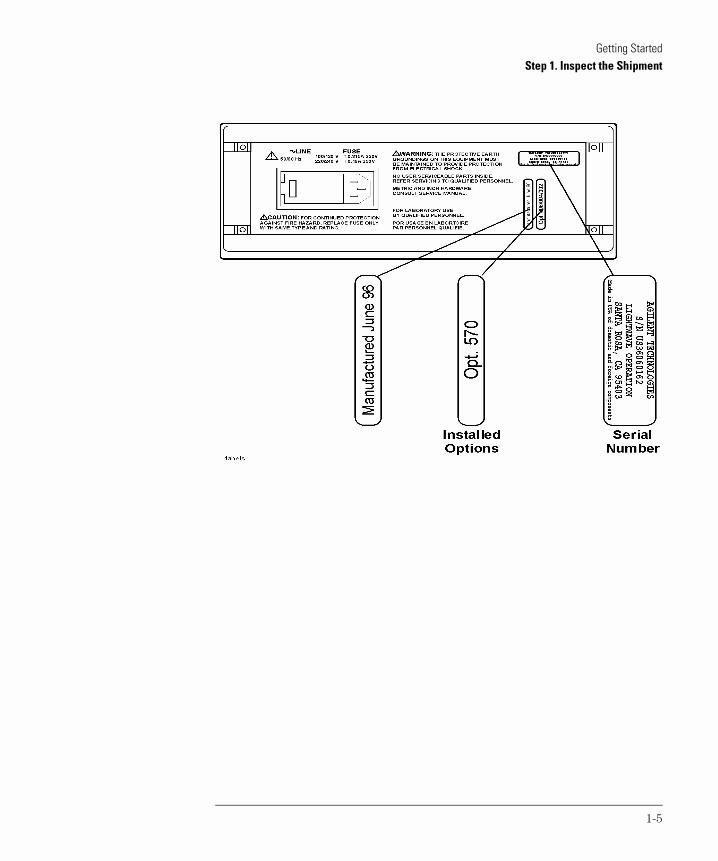
2 Make sure that the serial number and options listed on the instrument’s rear-panel label match the serial number and options listed on the shipping document. The following figure shows the position of the rear-panel serial number label:
1-4
Getting StartedStep 1. Inspect the Shipment
1-5
Getting StartedStep 2. Check the Fuse
Step 2. Check the Fuse
C A U T I O N Before connecting the lightwave receiver to the power source, you must set the rear-panel voltage selector correctly to adapt the lightwave receiver to the power source. An improper selector setting can damage the Agilent 83430A when it is turned on.
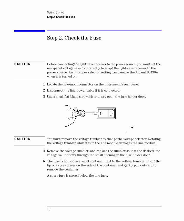
1 Locate the line-input connector on the instrument’s rear panel.
2 Disconnect the line-power cable if it is connected.
3 Use a small flat-blade screwdriver to pry open the fuse holder door.
C A U T I O N You must remove the voltage tumbler to change the voltage selector. Rotating the voltage tumbler while it is in the line module damages the line module.
4 Remove the voltage tumbler, and replace the tumbler so that the desired line voltage value shows through the small opening in the fuse holder door.
5 The fuse is housed in a small container next to the voltage tumbler. Insert the tip of a screwdriver on the side of the container and gently pull outward to remove the container.
A spare fuse is stored below the line fuse.
1-6
Getting StartedStep 2. Check the Fuse
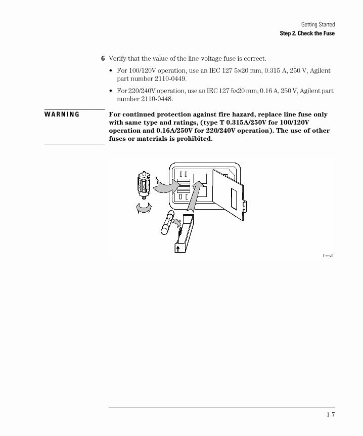
6 Verify that the value of the line-voltage fuse is correct.
• For 100/120V operation, use an IEC 127 5×20 mm, 0.315 A, 250 V, Agilent part number 2110-0449.
• For 220/240V operation, use an IEC 127 5×20 mm, 0.16 A, 250 V, Agilent part number 2110-0448.
W A R N I N G For continued protection against fire hazard, replace line fuse only
with same type and ratings, (type T 0.315A/250V for 100/120V
operation and 0.16A/250V for 220/240V operation). The use of other
fuses or materials is prohibited.
1-7
Getting StartedStep 3. Connect the Line-Power Cable
Step 3. Connect the Line-Power Cable
C A U T I O N Always use the three-prong AC power cord supplied with this instrument. Failure to ensure adequate earth grounding by not using this cord may cause instrument damage.
C A U T I O N Do not connect ac power until you have verified the line voltage is correct as described in the following paragraphs. Damage to the equipment could result.
C A U T I O N This instrument has autoranging line voltage input. Be sure the supply voltage is within the specified range.
1 Verify that the line power meets the requirements shown in the following table.
2 Connect the line-power cord to the instrument’s rear-panel connector.
Line Power Requirements
Power 115 VAC: 50 WATTS MAX 230 VAC: 50 WATTS MAX
Voltage nominal: 115 VAC range:90–132 V
nominal:230 VACrange:98–254 V
Frequency nominal: 50 Hz/60 Hzrange: 47–63 Hz
1-8
Getting StartedStep 3. Connect the Line-Power Cable
3 Connect the other end of the line-power cord to the power receptacle.
Various power cables are available to connect the Agilent 83430A to ac power outlets unique to specific geographic areas. The cable appropriate for the area to which the Agilent 83430A is originally shipped is included with the unit. You can order additional ac power cables for use in different geographic areas. Refer to “Power Cords” on page 4-5.
1-9
Getting StartedStep 4. Turn on the Agilent 83430A
Step 4. Turn on the Agilent 83430A
• Press the front-panel LINE key.
The front-panel LINE switch disconnects the mains circuits from the mains sup-ply after the EMC filters and before other parts of the instrument.
If the Agilent 83430A fails to turn on properly, consider the following possibili-ties:
Is the line fuse good?
Does the line socket have power?
Is it plugged into the proper ac power source?
If the instrument still fails, return it to Agilent Technologies for repair. Refer to “Returning the Instrument for Service” on page 1-11.
1-10
Getting StartedReturning the Instrument for Service
Returning the Instrument for Service
The instructions in this section show you how to properly return the instru-ment for repair or calibration. Always call the Agilent Technologies Instrument Support Center first to initiate service before returning your instrument to a service office. This ensures that the repair (or calibration) can be properly tracked and that your instrument will be returned to you as quickly as possi-ble. Call this number regardless of where you are located. Refer to “Agilent Technologies Service Offices” on page 4-6 for a list of service offices.
Agilent Technologies Instrument Support Center. . . . . . . . . . . (800) 403-0801
If the instrument is still under warranty or is covered by an Agilent Technolo-gies maintenance contract, it will be repaired under the terms of the warranty or contract (the warranty is at the front of this manual). If the instrument is no longer under warranty or is not covered by an Agilent Technologies mainte-nance plan, Agilent Technologies will notify you of the cost of the repair after examining the unit.
When an instrument is returned to a Agilent Technologies service office for servicing, it must be adequately packaged and have a complete description of the failure symptoms attached. When describing the failure, please be as spe-cific as possible about the nature of the problem. Include copies of additional failure information (such as the instrument failure settings, data related to instrument failure, and error messages) along with the instrument being returned.
Preparing the instrument for shipping
1 Write a complete description of the failure and attach it to the instrument. Include any specific performance details related to the problem. The following
1-11
Getting StartedReturning the Instrument for Service
information should be returned with the instrument.
• Type of service required. • Date instrument was returned for repair. • Description of the problem:
• Whether problem is constant or intermittent. • Whether instrument is temperature-sensitive. • Whether instrument is vibration-sensitive. • Instrument settings required to reproduce the problem. • Performance data.
• Company name and return address. • Name and phone number of technical contact person. • Model number of returned instrument. • Full serial number of returned instrument. • List of any accessories returned with instrument.
2 Cover all front or rear-panel connectors that were originally covered when you first received the instrument.
C A U T I O N Cover electrical connectors to protect sensitive components from electrostatic damage. Cover optical connectors to protect them from damage due to physical contact or dust.
C A U T I O N Instrument damage can result from using packaging materials other than the original materials. Never use styrene pellets as packaging material. They do not adequately cushion the instrument or prevent it from shifting in the carton. They may also cause instrument damage by generating static electricity.
3 Pack the instrument in the original shipping containers. Original materials are available through any Agilent Technologies office. Or, use the following guidelines:
• Wrap the instrument in antistatic plastic to reduce the possibility of damage caused by electrostatic discharge.
• For instruments weighing less than 54 kg (120 lb), use a double-walled, cor-rugated cardboard carton of 159 kg (350 lb) test strength.
• The carton must be large enough to allow approximately 7 cm (3 inches) on all sides of the instrument for packing material, and strong enough to accom-modate the weight of the instrument.
• Surround the equipment with approximately 7 cm (3 inches) of packing ma-terial, to protect the instrument and prevent it from moving in the carton. If packing foam is not available, the best alternative is S.D-240 Air Cap™ from
1-12
Getting StartedReturning the Instrument for Service
Sealed Air Corporation (Commerce, California 90001). Air Cap looks like a plastic sheet filled with air bubbles. Use the pink (antistatic) Air Cap™ to reduce static electricity. Wrapping the instrument several times in this ma-terial will protect the instrument and prevent it from moving in the carton.
4 Seal the carton with strong nylon adhesive tape.
5 Mark the carton “FRAGILE, HANDLE WITH CARE”.
6 Retain copies of all shipping papers.
1-13

2
Using the Agilent 83430A 2-3Front-panel Features 2-3Example Uses 2-5
Cleaning Connections for Accurate Measurements 2-9
Making Measurements
Making MeasurementsMaking Measurements
Making Measurements
In this chapter, you’ll find examples of making measurements using the Agilent 83430A.
The last section of this chapter explains how to maintain top performance of your instrument by using proper handling and cleaning techniques. Be sure to read this section before using your Agilent 83430A.
2-2
Making MeasurementsUsing the Agilent 83430A
Using the Agilent 83430A
Front-panel Features
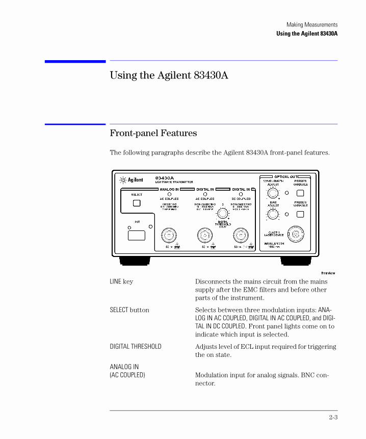
The following paragraphs describe the Agilent 83430A front-panel features.
LINE key Disconnects the mains circuit from the mains supply after the EMC filters and before other parts of the instrument.
SELECT button Selects between three modulation inputs: ANA-LOG IN AC COUPLED, DIGITAL IN AC COUPLED, and DIGI-TAL IN DC COUPLED. Front panel lights come on to indicate which input is selected.
DIGITAL THRESHOLD Adjusts level of ECL input required for triggering the on state.
ANALOG IN (AC COUPLED) Modulation input for analog signals. BNC con-
nector.
2-3
Making MeasurementsUsing the Agilent 83430A
DIGITAL IN (AC COUPLED) Modulation input for digital signals. The input is AC coupled. BNC connector.
DIGITAL IN (DC COUPLED) Modulation input for analog signals. This input is
DC coupled. BNC connector.
WAVELENGTH ADJUST knob Allows you to adjust the laser’s wavelength when the variable mode is activated. Press the PRESET/VARIABLE button so that the front-panel light turns on.
PRESET/VARIABLE button Toggles between preset laser wavelength or amplitude settings. (Light turns on to indicate you can adjust the setting using the knob.).
BIAS ADJUST knob Allows you to adjust the laser’s output amplitude when variable mode is activated. Press the PRE-SET/VARIABLE button so that the front-panel light turns on.
OPTICAL OUT connector This connector provides the instrument’s laser output. A universal adapter is used that can be removed and replaced with different adapters as needed (refer to “Front-Panel Fiber-Optic Adapters” on page 4-4).
2-4
Making MeasurementsUsing the Agilent 83430A
Example Uses
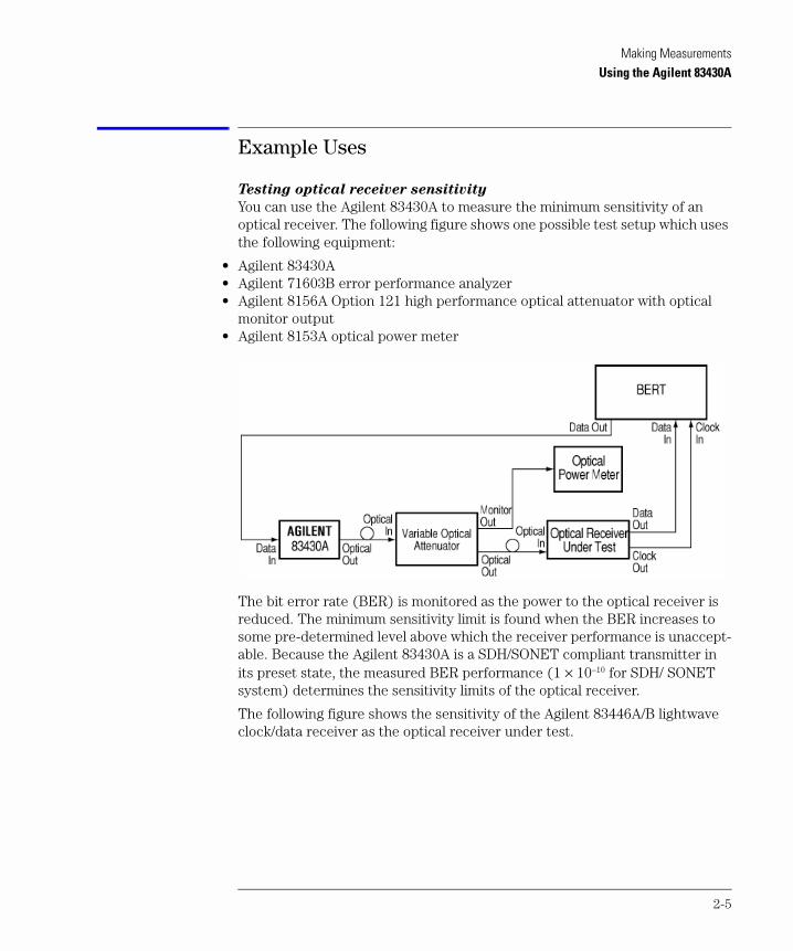
Testing optical receiver sensitivity
You can use the Agilent 83430A to measure the minimum sensitivity of an optical receiver. The following figure shows one possible test setup which uses the following equipment:
• Agilent 83430A• Agilent 71603B error performance analyzer• Agilent 8156A Option 121 high performance optical attenuator with optical
monitor output• Agilent 8153A optical power meter
The bit error rate (BER) is monitored as the power to the optical receiver is reduced. The minimum sensitivity limit is found when the BER increases to some pre-determined level above which the receiver performance is unaccept-able. Because the Agilent 83430A is a SDH/SONET compliant transmitter in its preset state, the measured BER performance (1 × 10⁻¹⁰ for SDH/ SONET system) determines the sensitivity limits of the optical receiver.
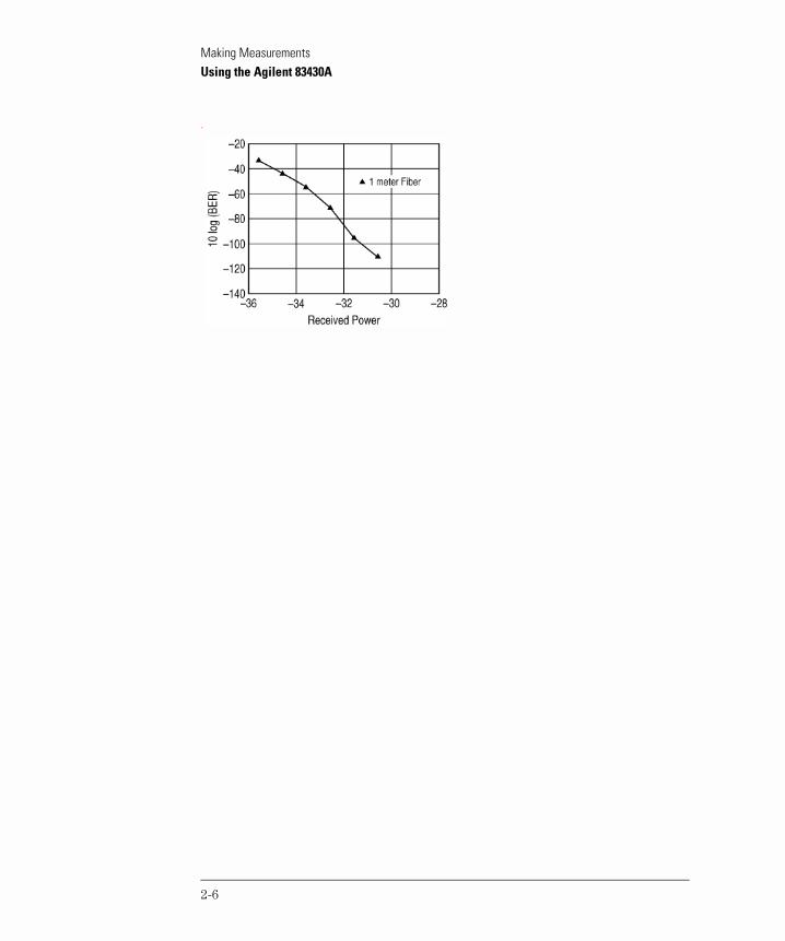
The following figure shows the sensitivity of the Agilent 83446A/B lightwave clock/data receiver as the optical receiver under test.
2-5
Making MeasurementsUsing the Agilent 83430A
.
2-6
Making MeasurementsUsing the Agilent 83430A
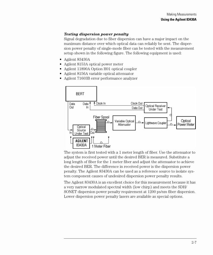
Testing dispersion power penalty
Signal degradation due to fiber dispersion can have a major impact on the maximum distance over which optical data can reliably be sent. The disper-sion power penalty of single-mode fiber can be tested with the measurement setup shown in the following figure. The following equipment is used:
• Agilent 83430A• Agilent 8153A optical power meter• Agilent 11890A Option H01 optical coupler• Agilent 8156A variable optical attenuator• Agilent 71603B error performance analyzer
The system is first tested with a 1 meter length of fiber. Use the attenuator to adjust the received power until the desired BER is measured. Substitute a long length of fiber for the 1 meter fiber and adjust the attenuator to achieve the desired BER. The difference in received power is the dispersion power penalty. The Agilent 83430A can be used as a reference source to isolate sys-tem component causes of undesired dispersion power penalty results.
The Agilent 83430A is an excellent choice for this measurement because it has a very narrow modulated spectral width (low chirp) and meets the SDH/ SONET dispersion power penalty requirement at 1200 ps/nm fiber dispersion. Lower dispersion power penalty lasers are available as special options.
2-7
Making MeasurementsUsing the Agilent 83430A
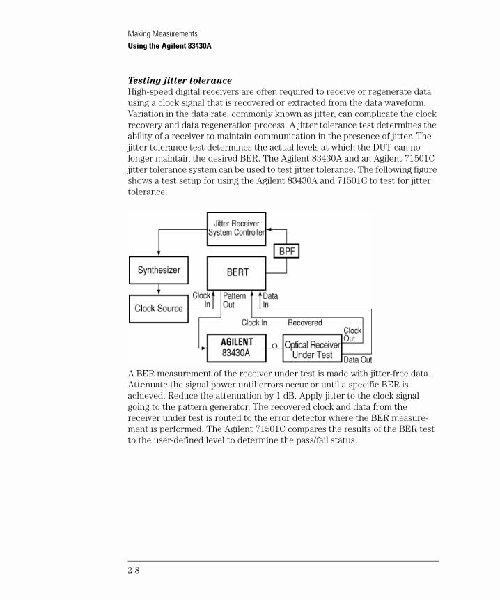
Testing jitter tolerance
High-speed digital receivers are often required to receive or regenerate data using a clock signal that is recovered or extracted from the data waveform. Variation in the data rate, commonly known as jitter, can complicate the clock recovery and data regeneration process. A jitter tolerance test determines the ability of a receiver to maintain communication in the presence of jitter. The jitter tolerance test determines the actual levels at which the DUT can no longer maintain the desired BER. The Agilent 83430A and an Agilent 71501C jitter tolerance system can be used to test jitter tolerance. The following figure shows a test setup for using the Agilent 83430A and 71501C to test for jitter tolerance.
A BER measurement of the receiver under test is made with jitter-free data. Attenuate the signal power until errors occur or until a specific BER is achieved. Reduce the attenuation by 1 dB. Apply jitter to the clock signal going to the pattern generator. The recovered clock and data from the receiver under test is routed to the error detector where the BER measure-ment is performed. The Agilent 71501C compares the results of the BER test to the user-defined level to determine the pass/fail status.
2-8

Making MeasurementsCleaning Connections for Accurate Measurements
Cleaning Connections for Accurate Measurements
Today, advances in measurement capabilities make connectors and connec-tion techniques more important than ever. Damage to the connectors on cali-bration and verification devices, test ports, cables, and other devices can degrade measurement accuracy and damage instruments. Replacing a dam-aged connector can cost thousands of dollars, not to mention lost time! This expense can be avoided by observing the simple precautions presented in this book. This book also contains a brief list of tips for caring for electrical connec-tors.
Choosing the Right Connector
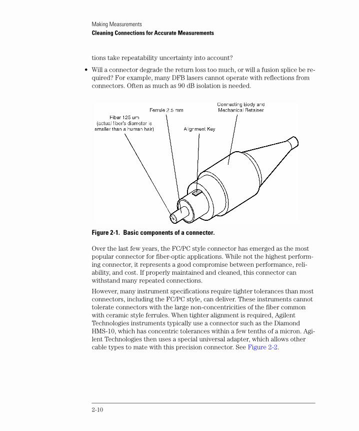
A critical but often overlooked factor in making a good lightwave measure-ment is the selection of the fiber-optic connector. The differences in connec-tor types are mainly in the mechanical assembly that holds the ferrule in position against another identical ferrule. Connectors also vary in the polish, curve, and concentricity of the core within the cladding. Mating one style of cable to another requires an adapter. Agilent Technologies offers adapters for most instruments to allow testing with many different cables. Figure 2-1 on page 2-10 shows the basic components of a typical connectors.
The system tolerance for reflection and insertion loss must be known when selecting a connector from the wide variety of currently available connectors. Some items to consider when selecting a connector are:
• How much insertion loss can be allowed?
• Will the connector need to make multiple connections? Some connectors are better than others, and some are very poor for making repeated connections.
• What is the reflection tolerance? Can the system take reflection degradation?
• Is an instrument-grade connector with a precision core alignment required?
• Is repeatability tolerance for reflection and loss important? Do your specifica-
2-9
Making MeasurementsCleaning Connections for Accurate Measurements
tions take repeatability uncertainty into account?
• Will a connector degrade the return loss too much, or will a fusion splice be re-quired? For example, many DFB lasers cannot operate with reflections from connectors. Often as much as 90 dB isolation is needed.
Figure 2-1. Basic components of a connector.
Over the last few years, the FC/PC style connector has emerged as the most popular connector for fiber-optic applications. While not the highest perform-ing connector, it represents a good compromise between performance, reli-ability, and cost. If properly maintained and cleaned, this connector can withstand many repeated connections.
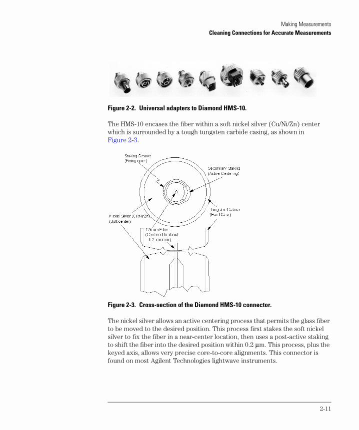
However, many instrument specifications require tighter tolerances than most connectors, including the FC/PC style, can deliver. These instruments cannot tolerate connectors with the large non-concentricities of the fiber common with ceramic style ferrules. When tighter alignment is required, Agilent Technologies instruments typically use a connector such as the Diamond HMS-10, which has concentric tolerances within a few tenths of a micron. Agi-lent Technologies then uses a special universal adapter, which allows other cable types to mate with this precision connector. See Figure 2-2.
2-10
Making MeasurementsCleaning Connections for Accurate Measurements
Figure 2-2. Universal adapters to Diamond HMS-10.
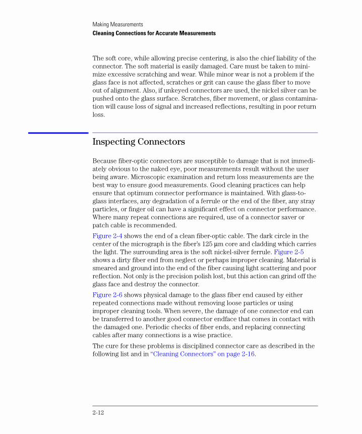
The HMS-10 encases the fiber within a soft nickel silver (Cu/Ni/Zn) center which is surrounded by a tough tungsten carbide casing, as shown in Figure 2-3.
Figure 2-3. Cross-section of the Diamond HMS-10 connector.
The nickel silver allows an active centering process that permits the glass fiber to be moved to the desired position. This process first stakes the soft nickel silver to fix the fiber in a near-center location, then uses a post-active staking to shift the fiber into the desired position within 0.2 µm. This process, plus the keyed axis, allows very precise core-to-core alignments. This connector is found on most Agilent Technologies lightwave instruments.
2-11
Making MeasurementsCleaning Connections for Accurate Measurements
The soft core, while allowing precise centering, is also the chief liability of the connector. The soft material is easily damaged. Care must be taken to mini-mize excessive scratching and wear. While minor wear is not a problem if the glass face is not affected, scratches or grit can cause the glass fiber to move out of alignment. Also, if unkeyed connectors are used, the nickel silver can be pushed onto the glass surface. Scratches, fiber movement, or glass contamina-tion will cause loss of signal and increased reflections, resulting in poor return loss.
Inspecting Connectors
Because fiber-optic connectors are susceptible to damage that is not immedi-ately obvious to the naked eye, poor measurements result without the user being aware. Microscopic examination and return loss measurements are the best way to ensure good measurements. Good cleaning practices can help ensure that optimum connector performance is maintained. With glass-to-glass interfaces, any degradation of a ferrule or the end of the fiber, any stray particles, or finger oil can have a significant effect on connector performance. Where many repeat connections are required, use of a connector saver or patch cable is recommended.
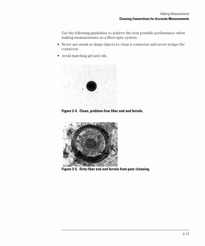
Figure 2-4 shows the end of a clean fiber-optic cable. The dark circle in the center of the micrograph is the fiber’s 125 µm core and cladding which carries the light. The surrounding area is the soft nickel-silver ferrule. Figure 2-5 shows a dirty fiber end from neglect or perhaps improper cleaning. Material is smeared and ground into the end of the fiber causing light scattering and poor reflection. Not only is the precision polish lost, but this action can grind off the glass face and destroy the connector.
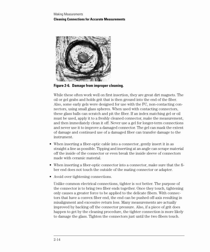
Figure 2-6 shows physical damage to the glass fiber end caused by either repeated connections made without removing loose particles or using improper cleaning tools. When severe, the damage of one connector end can be transferred to another good connector endface that comes in contact with the damaged one. Periodic checks of fiber ends, and replacing connecting cables after many connections is a wise practice.
The cure for these problems is disciplined connector care as described in the following list and in “Cleaning Connectors” on page 2-16.
2-12
Making MeasurementsCleaning Connections for Accurate Measurements
Use the following guidelines to achieve the best possible performance when making measurements on a fiber-optic system:
• Never use metal or sharp objects to clean a connector and never scrape the connector.
• Avoid matching gel and oils.
Figure 2-4. Clean, problem-free fiber end and ferrule.
Figure 2-5. Dirty fiber end and ferrule from poor cleaning.
2-13
Making MeasurementsCleaning Connections for Accurate Measurements
Figure 2-6. Damage from improper cleaning.
While these often work well on first insertion, they are great dirt magnets. The oil or gel grabs and holds grit that is then ground into the end of the fiber. Also, some early gels were designed for use with the FC, non-contacting con-nectors, using small glass spheres. When used with contacting connectors, these glass balls can scratch and pit the fiber. If an index matching gel or oil must be used, apply it to a freshly cleaned connector, make the measurement, and then immediately clean it off. Never use a gel for longer-term connections and never use it to improve a damaged connector. The gel can mask the extent of damage and continued use of a damaged fiber can transfer damage to the instrument.
• When inserting a fiber-optic cable into a connector, gently insert it in as straight a line as possible. Tipping and inserting at an angle can scrape material off the inside of the connector or even break the inside sleeve of connectors made with ceramic material.
• When inserting a fiber-optic connector into a connector, make sure that the fi-ber end does not touch the outside of the mating connector or adapter.
• Avoid over tightening connections.
Unlike common electrical connections, tighter is not better. The purpose of the connector is to bring two fiber ends together. Once they touch, tightening only causes a greater force to be applied to the delicate fibers. With connec-tors that have a convex fiber end, the end can be pushed off-axis resulting in misalignment and excessive return loss. Many measurements are actually improved by backing off the connector pressure. Also, if a piece of grit does happen to get by the cleaning procedure, the tighter connection is more likely to damage the glass. Tighten the connectors just until the two fibers touch.
2-14
Making MeasurementsCleaning Connections for Accurate Measurements
• Keep connectors covered when not in use.
• Use fusion splices on the more permanent critical nodes. Choose the best con-nector possible. Replace connecting cables regularly. Frequently measure the return loss of the connector to check for degradation, and clean every connec-tor, every time.
All connectors should be treated like the high-quality lens of a good camera. The weak link in instrument and system reliability is often the inappropriate use and care of the connector. Because current connectors are so easy to use, there tends to be reduced vigilance in connector care and cleaning. It takes only one missed cleaning for a piece of grit to permanently damage the glass and ruin the connector.
Measuring insertion loss and return loss
Consistent measurements with your lightwave equipment are a good indica-tion that you have good connections. Since return loss and insertion loss are key factors in determining optical connector performance they can be used to determine connector degradation. A smooth, polished fiber end should pro-duce a good return-loss measurement. The quality of the polish establishes the difference between the “PC” (physical contact) and the “Super PC” con-nectors. Most connectors today are physical contact which make glass-to-glass connections, therefore it is critical that the area around the glass core be clean and free of scratches. Although the major area of a connector, excluding the glass, may show scratches and wear, if the glass has maintained its polished smoothness, the connector can still provide a good low level return loss con-nection.
If you test your cables and accessories for insertion loss and return loss upon receipt, and retain the measured data for comparison, you will be able to tell in the future if any degradation has occurred. Typical values are less than 0.5 dB of loss, and sometimes as little as 0.1 dB of loss with high performance con-nectors. Return loss is a measure of reflection: the less reflection the better (the larger the return loss, the smaller the reflection). The best physically contacting connectors have return losses better than 50 dB, although 30 to 40 dB is more common.
2-15
Making MeasurementsCleaning Connections for Accurate Measurements
Visual inspection of fiber ends
Visual inspection of fiber ends can be helpful. Contamination or imperfections on the cable end face can be detected as well as cracks or chips in the fiber itself. Use a microscope (100X to 200X magnification) to inspect the entire end face for contamination, raised metal, or dents in the metal as well as any other imperfections. Inspect the fiber for cracks and chips. Visible imperfec-tions not touching the fiber core may not affect performance (unless the imperfections keep the fibers from contacting).
W A R N I N G Always remove both ends of fiber-optic cables from any instrument,
system, or device before visually inspecting the fiber ends. Disable all
optical sources before disconnecting fiber-optic cables. Failure to do
so may result in permanent injury to your eyes.
Cleaning Connectors
The procedures in this section provide the proper steps for cleaning fiber-optic cables and Agilent Technologies universal adapters. The initial cleaning, using the alcohol as a solvent, gently removes any grit and oil. If a caked-on layer of material is still present, (this can happen if the beryllium-copper sides of the ferrule retainer get scraped and deposited on the end of the fiber during insertion of the cable), a second cleaning should be performed. It is not uncommon for a cable or connector to require more than one cleaning.
C A U T I O N Agilent Technologies strongly recommends that index matching compounds not be applied to their instruments and accessories. Some compounds, such as gels, may be difficult to remove and can contain damaging particulates. If you think the use of such compounds is necessary, refer to the compound manufacturer for information on application and cleaning procedures.
Table 2-1. Cleaning Accessories
Item Agilent Part Number
Pure isoporpyl alcohol —
Cotton swabs 8520-0023
Small foam swabs 9300-1223
Compressed dust remover (non-residue) 8500-5262
2-16
Making MeasurementsCleaning Connections for Accurate Measurements
To clean a non-lensed connector
C A U T I O N Do not use any type of foam swab to clean optical fiber ends. Foam swabs can leave filmy deposits on fiber ends that can degrade performance.
1 Apply pure isopropyl alcohol to a clean lint-free cotton swab or lens paper.
Cotton swabs can be used as long as no cotton fibers remain on the fiber end after cleaning.
2 Clean the ferrules and other parts of the connector while avoiding the end of the fiber.
3 Apply isopropyl alcohol to a new clean lint-free cotton swab or lens paper.
4 Clean the fiber end with the swab or lens paper.
Do not scrub during this initial cleaning because grit can be caught in the swab and become a gouging element.
5 Immediately dry the fiber end with a clean, dry, lint-free cotton swab or lens paper.
6 Blow across the connector end face from a distance of 6 to 8 inches using filtered, dry, compressed air. Aim the compressed air at a shallow angle to the fiber end face.
Nitrogen gas or compressed dust remover can also be used.
Table 2-2. Dust Caps Provided with Lightwave Instruments
Item Agilent Part Number
Laser shutter cap 08145-64521
FC/PC dust cap 08154-44102
Biconic dust cap 08154-44105
DIN dust cap 5040-9364
HMS10/dust cap 5040-9361
ST dust cap 5040-9366
2-17
Making MeasurementsCleaning Connections for Accurate Measurements
C A U T I O N Do not shake, tip, or invert compressed air canisters, because this releases particles in the can into the air. Refer to instructions provided on the compressed air canister.
7 As soon as the connector is dry, connect or cover it for later use.
If the performance, after the initial cleaning, seems poor try cleaning the con-nector again. Often a second cleaning will restore proper performance. The second cleaning should be more arduous with a scrubbing action.
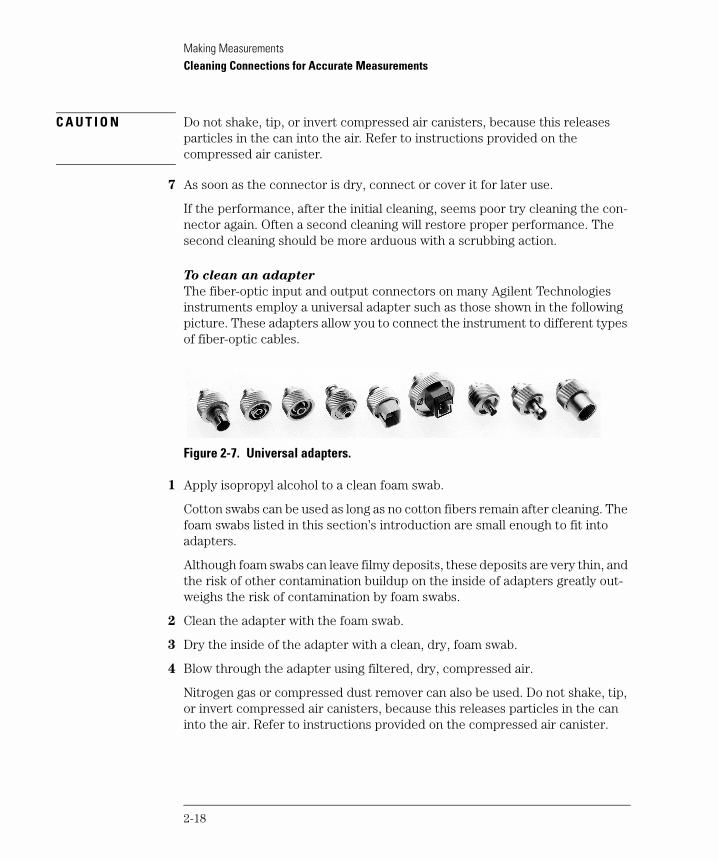
To clean an adapter
The fiber-optic input and output connectors on many Agilent Technologies instruments employ a universal adapter such as those shown in the following picture. These adapters allow you to connect the instrument to different types of fiber-optic cables.
Figure 2-7. Universal adapters.
1 Apply isopropyl alcohol to a clean foam swab.
Cotton swabs can be used as long as no cotton fibers remain after cleaning. The foam swabs listed in this section’s introduction are small enough to fit into adapters.
Although foam swabs can leave filmy deposits, these deposits are very thin, and the risk of other contamination buildup on the inside of adapters greatly out-weighs the risk of contamination by foam swabs.
2 Clean the adapter with the foam swab.
3 Dry the inside of the adapter with a clean, dry, foam swab.
4 Blow through the adapter using filtered, dry, compressed air.
Nitrogen gas or compressed dust remover can also be used. Do not shake, tip, or invert compressed air canisters, because this releases particles in the can into the air. Refer to instructions provided on the compressed air canister.
2-18

3
Specifications 3-3Regulatory Information 3-6
Specifications and Regulatory Information

Specifications and Regulatory InformationSpecifications and Regulatory Information
Specifications and Regulatory Information
This chapter lists specification and characteristics of the instrument. The dis-tinction between these terms is described as follows:
• Specifications describe warranted performance over the temperature range 0°C to +45°C and relative humidity <95% (unless otherwise noted). All speci-fications apply after the instrument’s temperature has been stabilized after 15 minutes of continuous operation.
• Characteristics provide useful information by giving functional, but nonwarrant-ed, performance parameters. Characteristics are printed in this typeface.
Calibration cycle
This instrument requires periodic verification of performance. The instrument should have a complete verification of specifications at least once every two years.
3-2
Specifications and Regulatory InformationSpecifications
Specifications
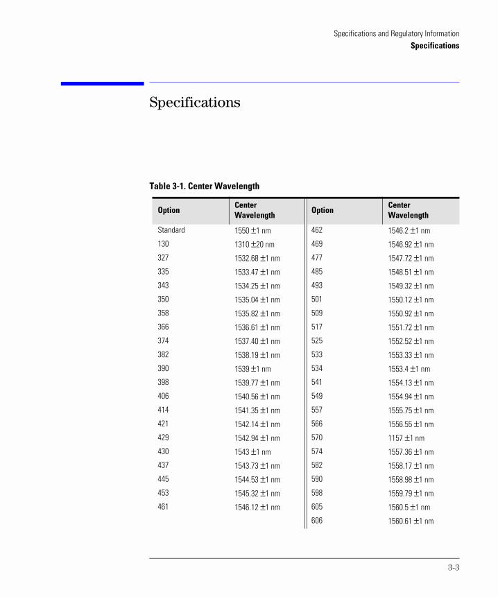
Table 3-1. Center Wavelength
OptionCenterWavelength
OptionCenterWavelength
Standard 1550 ±1 nm 462 1546.2 ±1 nm
130 1310 ±20 nm 469 1546.92 ±1 nm
327 1532.68 ±1 nm 477 1547.72 ±1 nm
335 1533.47 ±1 nm 485 1548.51 ±1 nm
343 1534.25 ±1 nm 493 1549.32 ±1 nm
350 1535.04 ±1 nm 501 1550.12 ±1 nm
358 1535.82 ±1 nm 509 1550.92 ±1 nm
366 1536.61 ±1 nm 517 1551.72 ±1 nm
374 1537.40 ±1 nm 525 1552.52 ±1 nm
382 1538.19 ±1 nm 533 1553.33 ±1 nm
390 1539 ±1 nm 534 1553.4 ±1 nm
398 1539.77 ±1 nm 541 1554.13 ±1 nm
406 1540.56 ±1 nm 549 1554.94 ±1 nm
414 1541.35 ±1 nm 557 1555.75 ±1 nm
421 1542.14 ±1 nm 566 1556.55 ±1 nm
429 1542.94 ±1 nm 570 1157 ±1 nm
430 1543 ±1 nm 574 1557.36 ±1 nm
437 1543.73 ±1 nm 582 1558.17 ±1 nm
445 1544.53 ±1 nm 590 1558.98 ±1 nm
453 1545.32 ±1 nm 598 1559.79 ±1 nm
461 1546.12 ±1 nm 605 1560.5 ±1 nm
606 1560.61 ±1 nm
3-3
Specifications and Regulatory InformationSpecifications
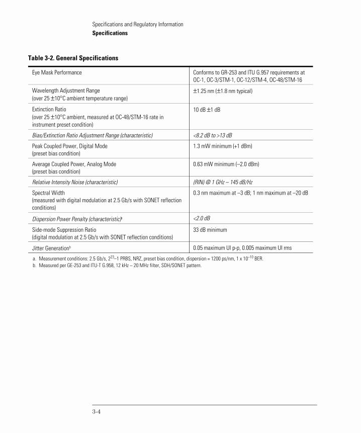
Table 3-2. General Specifications
Eye Mask Performance Conforms to GR-253 and ITU G.957 requirements at OC-1, OC-3/STM-1, OC-12/STM-4, OC-48/STM-16
Wavelength Adjustment Range (over 25 ±10°C ambient temperature range)
±1.25 nm (±1.8 nm typical)
Extinction Ratio (over 25 ±10°C ambient, measured at OC-48/STM-16 rate in instrument preset condition)
10 dB ±1 dB
Bias/Extinction Ratio Adjustment Range (characteristic) <8.2 dB to >13 dB
Peak Coupled Power, Digital Mode (preset bias condition)
1.3 mW minimum (+1 dBm)
Average Coupled Power, Analog Mode (preset bias condition)
0.63 mW minimum (–2.0 dBm)
Relative Intensity Noise (characteristic) (RIN) @ 1 GHz – 145 dB/Hz
Spectral Width (measured with digital modulation at 2.5 Gb/s with SONET reflection conditions)
0.3 nm maximum at –3 dB; 1 nm maximum at –20 dB
Dispersion Power Penalty (characteristic)a <2.0 dB
Side-mode Suppression Ratio (digital modulation at 2.5 Gb/s with SONET reflection conditions)
33 dB minimum
Jitter Generationb 0.05 maximum UI p-p, 0.005 maximum UI rms
a. Measurement conditions: 2.5 Gb/s, 223–1 PRBS, NRZ, preset bias condition, dispersion = 1200 ps/nm, 1 x 10⁻¹⁰ BER.b. Measured per GE-253 and ITU-T G.958, 12 kHz – 20 MHz filter, SDH/SONET pattern.
3-4
Specifications and Regulatory InformationSpecifications
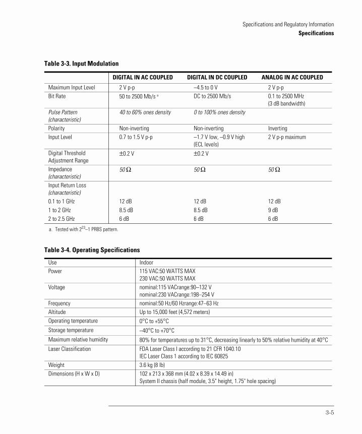
Table 3-3. Input Modulation
DIGITAL IN AC COUPLED DIGITAL IN DC COUPLED ANALOG IN AC COUPLED
Maximum Input Level 2 V p-p –4.5 to 0 V 2 V p-pBit Rate 50 to 2500 Mb/s a DC to 2500 Mb/s 0.1 to 2500 MHz
(3 dB bandwidth)Pulse Pattern (characteristic)
40 to 60% ones density 0 to 100% ones density
Polarity Non-inverting Non-inverting InvertingInput Level 0.7 to 1.5 V p-p –1.7 V low, –0.9 V high
(ECL levels)2 V p-p maximum
Digital Threshold Adjustment Range
±0.2 V ±0.2 V
Impedance (characteristic)
50 Ω 50 Ω 50 Ω
Input Return Loss (characteristic)0.1 to 1 GHz 12 dB 12 dB 12 dB1 to 2 GHz 8.5 dB 8.5 dB 9 dB2 to 2.5 GHz 6 dB 6 dB 6 dB
a. Tested with 223–1 PRBS pattern.
Table 3-4. Operating Specifications
Use IndoorPower 115 VAC:50 WATTS MAX
230 VAC:50 WATTS MAXVoltage nominal:115 VACrange:90–132 V
nominal:230 VACrange:198–254 VFrequency nominal:50 Hz/60 Hzrange:47–63 HzAltitude Up to 15,000 feet (4,572 meters)Operating temperature 0°C to +55°CStorage temperature –40°C to +70°CMaximum relative humidity 80% for temperatures up to 31°C, decreasing linearly to 50% relative humidity at 40°CLaser Classification FDA Laser Class I according to 21 CFR 1040.10
IEC Laser Class 1 according to IEC 60825Weight 3.6 kg (8 lb)Dimensions (H x W x D) 102 x 213 x 368 mm (4.02 x 8.39 x 14.49 in)
System II chassis (half module, 3.5" height, 1.75" hole spacing)
3-5
Specifications and Regulatory InformationRegulatory Information
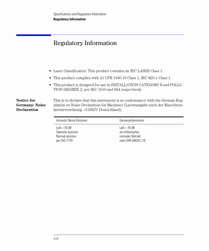
Regulatory Information
• Laser Classification: This product contains an IEC LASER Class 1.
• This product complies with 21 CFR 1040.10 Class 1, IEC 825-1 Class 1.
• This product is designed for use in INSTALLATION CATEGORY II and POLLU-TION DEGREE 2, per IEC 1010 and 664 respectively.
Notice for
Germany: Noise
Declaration
This is to declare that this instrument is in conformance with the German Reg-ulation on Noise Declaration for Machines (Laermangabe nach der Maschinen-laermrerordnung –3.GSGV Deutschland).
Acoustic Noise Emission Geraeuschemission
LpA < 70 dBOperator positionNormal positionper ISO 7779
LpA < 70 dBam Arbeitsplatznormaler Betriebnach DIN 45635 t.19
3-6
Specifications and Regulatory InformationRegulatory Information
3-7

4
Options 4-2Front-Panel Fiber-Optic Adapters 4-4Power Cords 4-5Agilent Technologies Service Offices 4-6
Reference
ReferenceOptions
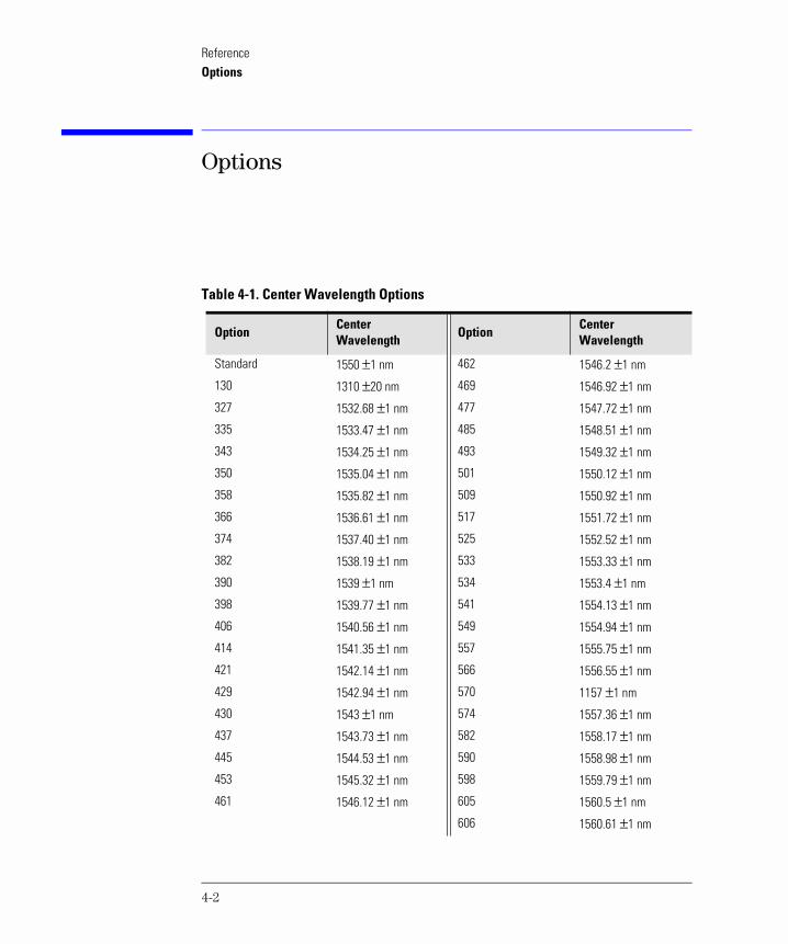
Options
Table 4-1. Center Wavelength Options
OptionCenterWavelength
OptionCenterWavelength
Standard 1550 ±1 nm 462 1546.2 ±1 nm
130 1310 ±20 nm 469 1546.92 ±1 nm
327 1532.68 ±1 nm 477 1547.72 ±1 nm
335 1533.47 ±1 nm 485 1548.51 ±1 nm
343 1534.25 ±1 nm 493 1549.32 ±1 nm
350 1535.04 ±1 nm 501 1550.12 ±1 nm
358 1535.82 ±1 nm 509 1550.92 ±1 nm
366 1536.61 ±1 nm 517 1551.72 ±1 nm
374 1537.40 ±1 nm 525 1552.52 ±1 nm
382 1538.19 ±1 nm 533 1553.33 ±1 nm
390 1539 ±1 nm 534 1553.4 ±1 nm
398 1539.77 ±1 nm 541 1554.13 ±1 nm
406 1540.56 ±1 nm 549 1554.94 ±1 nm
414 1541.35 ±1 nm 557 1555.75 ±1 nm
421 1542.14 ±1 nm 566 1556.55 ±1 nm
429 1542.94 ±1 nm 570 1157 ±1 nm
430 1543 ±1 nm 574 1557.36 ±1 nm
437 1543.73 ±1 nm 582 1558.17 ±1 nm
445 1544.53 ±1 nm 590 1558.98 ±1 nm
453 1545.32 ±1 nm 598 1559.79 ±1 nm
461 1546.12 ±1 nm 605 1560.5 ±1 nm
606 1560.61 ±1 nm
4-2
ReferenceOptions
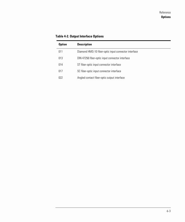
Table 4-2. Output Interface Options
Option Description
011 Diamond HMS-10 fiber-optic input connector interface
013 DIN 47256 fiber-optic input connector interface
014 ST fiber-optic input connector interface
017 SC fiber-optic input connector interface
022 Angled contact fiber-optic output interface
4-3
ReferenceFront-Panel Fiber-Optic Adapters
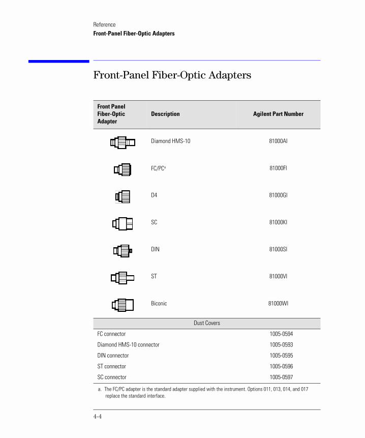
Front-Panel Fiber-Optic Adapters
Front PanelFiber-Optic Adapter
Description Agilent Part Number
Diamond HMS-10 81000AI
FC/PCa
a. The FC/PC adapter is the standard adapter supplied with the instrument. Options 011, 013, 014, and 017replace the standard interface.
81000FI
D4 81000GI
SC 81000KI
DIN 81000SI
ST 81000VI
Biconic 81000WI
Dust Covers
FC connector 1005-0594
Diamond HMS-10 connector 1005-0593
DIN connector 1005-0595
ST connector 1005-0596
SC connector 1005-0597
4-4
ReferencePower Cords
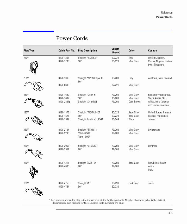
Power Cords
Plug Type Cable Part No. Plug DescriptionLength (in/cm)
Color Country
250V 8120-13518120-1703
Straight *BS1363A90°
90/22890/228
GrayMint Gray
United Kingdom, Cyprus, Nigeria, Zimba-bwe, Singapore
250V 8120-1369
8120-0696
Straight *NZSS198/ASC90°
79/200
87/221
Gray
Mint Gray
Australia, New Zealand
250V 8120-16898120-16928120-2857p
Straight *CEE7-Y1190°Straight (Shielded)
79/20079/20079/200
Mint GrayMint GrayCoco Brown
East and West Europe, Saudi Arabia, So. Africa, India (unpolar-ized in many nations)
125V 8120-13788120-15218120-1992
Straight *NEMA5-15P90°Straight (Medical) UL544
90/22890/22896/244
Jade GrayJade GrayBlack
United States, Canada, Mexico, Philippines, Taiwan
250V 8120-21048120-2296
Straight *SEV10111959-24507Type 12 90°
79/20079/200
Mint GrayMint Gray
Switzerland
220V 8120-29568120-2957
Straight *DHCK10790°
79/20079/200
Mint GrayMint Gray
Denmark
250V 8120-42118120-4600
Straight SABS16490°
79/20079/200
Jade Gray Republic of South AfricaIndia
100V 8120-47538120-4754
Straight MITI90°
90/23090/230
Dark Gray Japan
* Part number shown for plug is the industry identifier for the plug only. Number shown for cable is the Agilent Technologies part number for the complete cable including the plug.
4-5
ReferenceAgilent Technologies Service Offices
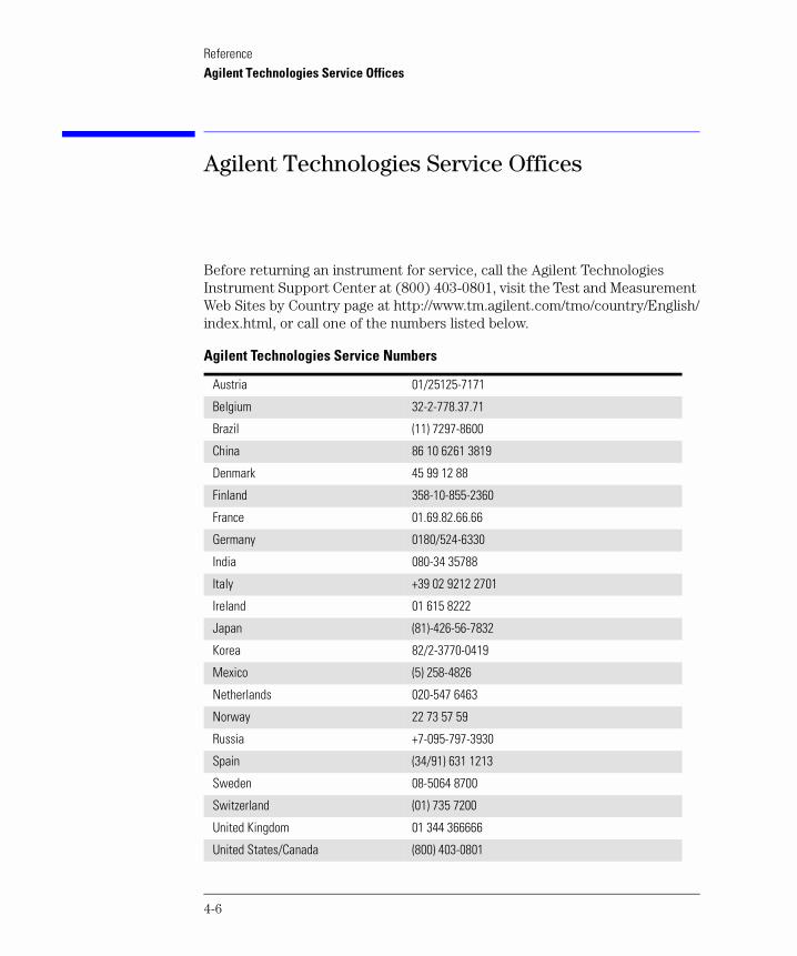
Agilent Technologies Service Offices
Before returning an instrument for service, call the Agilent Technologies Instrument Support Center at (800) 403-0801, visit the Test and Measurement Web Sites by Country page at http://www.tm.agilent.com/tmo/country/English/index.html, or call one of the numbers listed below.
Agilent Technologies Service Numbers
Austria 01/25125-7171
Belgium 32-2-778.37.71
Brazil (11) 7297-8600
China 86 10 6261 3819
Denmark 45 99 12 88
Finland 358-10-855-2360
France 01.69.82.66.66
Germany 0180/524-6330
India 080-34 35788
Italy +39 02 9212 2701
Ireland 01 615 8222
Japan (81)-426-56-7832
Korea 82/2-3770-0419
Mexico (5) 258-4826
Netherlands 020-547 6463
Norway 22 73 57 59
Russia +7-095-797-3930
Spain (34/91) 631 1213
Sweden 08-5064 8700
Switzerland (01) 735 7200
United Kingdom 01 344 366666
United States/Canada (800) 403-0801
4-6
5
General Information 5-4Electrostatic Discharge Information 5-7Troubleshooting 5-9
If the output power is low 5-10To check the line-power fuse 5-11
Performance Tests 5-13Test 1. Digital Threshold 5-15Test 2. Frequency Response (ANALOG IN) 5-17Test 3. Electrical Return Loss (ANALOG IN) 5-20Test 4. Electrical Return Loss (DIGITAL IN) 5-22Test 5. Eye Quality (DIGITAL IN) 5-24Test 6. STM-16/OC-48 Conformance 5-26Test 7. OC-1 Conformance 5-28Test 8. Output Power 5-31Test 9. Output Wavelength 5-33Configuring the pattern generator 5-35
Adjustment Procedures 5-36To remove the instrument cover 5-38Adjustment 1. Power Supply 5-39Adjustment 2. Laser Bias and Control 5-41
Replaceable Parts 5-45
Servicing
ServicingServicing
Servicing
In this chapter, you'll find information on troubleshooting, testing perfor-mance, adjusting, and replacing parts in the instrument.
W A R N I N G The laser assembly, A2A1, in this instrument is not field serviceable.
Safety first!
Before servicing the Agilent 83430A, familiarize yourself with the safety mark-ings on the instrument and the safety instructions in this manual. This instru-ment has been manufactured and tested according to international safety standards. To ensure safe operation of the instrument and the personal safety of the user and service personnel, the cautions and warnings in this manual must be heeded. Refer to the summary of safety considerations at the front of this manual.
W A R N I N G These servicing instructions are for use by qualified personnel only.
To avoid electrical shock, do not perform any servicing unless you are
qualified to do so.
W A R N I N G The opening of covers or removal of parts is likely to expose
dangerous voltages. Disconnect the instrument from all voltage
sources while it is being opened.
W A R N I N G The power cord is connected to internal capacitors that may remain
live for five seconds after disconnecting the plug from its power
supply.
W A R N I N G This is a Safety Class 1 Product (provided with a protective earthing
ground incorporated in the power cord). The mains plug shall only be
inserted in a socket outlet provided with a protective earth contact.
Any interruption of the protective conductor inside or outside of the
product is likely to make the product dangerous. Intentional
interruption is prohibited.
5-2
ServicingServicing
W A R N I N G For continued protection against fire hazard, replace line fuse only
with same type and ratings, (type T 0.315A/250V for 100/120V
operation and 0.16A/250V for 220/240V operation). The use of other
fuses or materials is prohibited.
W A R N I N G Use of controls or adjustment or performance of procedures other
than those specified herein may result in hazardous radiation
exposure.
5-3
ServicingGeneral Information
General Information
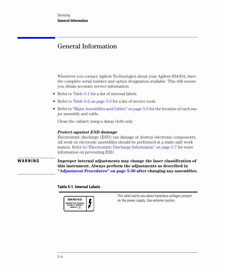
Whenever you contact Agilent Technologies about your Agilent 83430A, have the complete serial number and option designation available. This will ensure you obtain accurate service information.
• Refer to Table 5-1 for a list of internal labels.
• Refer to Table 5-2 on page 5-5 for a list of service tools.
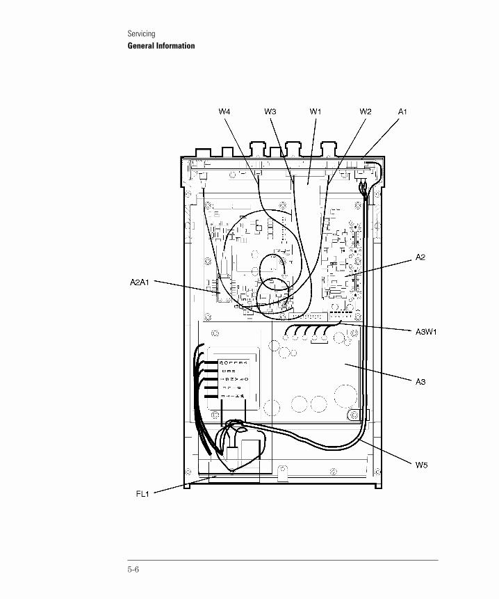
• Refer to “Major Assemblies and Cables” on page 5-5 for the location of each ma-jor assembly and cable.
Clean the cabinet using a damp cloth only.
Protect against ESD damage
Electrostatic discharge (ESD) can damage or destroy electronic components. All work on electronic assemblies should be performed at a static-safe work station. Refer to “Electrostatic Discharge Information” on page 5-7 for more information on preventing ESD.
W A R N I N G Improper internal adjustments may change the laser classification of
this instrument. Always perform the adjustments as described in
“Adjustment Procedures” on page 5-36 after changing any assemblies.
Table 5-1. Internal Labels
This label warns you about hazardous voltages present on the power supply. Use extreme caution.
5-4
ServicingGeneral Information
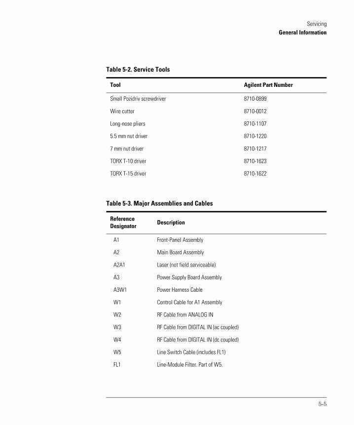
Table 5-2. Service Tools
Tool Agilent Part Number
Small Pozidriv screwdriver 8710-0899
Wire cutter 8710-0012
Long-nose pliers 8710-1107
5.5 mm nut driver 8710-1220
7 mm nut driver 8710-1217
TORX T-10 driver 8710-1623
TORX T-15 driver 8710-1622
Table 5-3. Major Assemblies and Cables
ReferenceDesignator
Description
A1 Front-Panel Assembly
A2 Main Board Assembly
A2A1 Laser (not field serviceable)
A3 Power Supply Board Assembly
A3W1 Power Harness Cable
W1 Control Cable for A1 Assembly
W2 RF Cable from ANALOG IN
W3 RF Cable from DIGITAL IN (ac coupled)
W4 RF Cable from DIGITAL IN (dc coupled)
W5 Line Switch Cable (includes FL1)
FL1 Line-Module Filter. Part of W5.
5-5
ServicingGeneral Information
5-6
ServicingElectrostatic Discharge Information
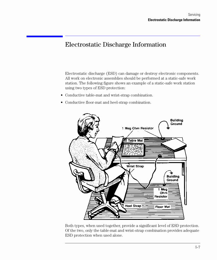
Electrostatic Discharge Information
Electrostatic discharge (ESD) can damage or destroy electronic components. All work on electronic assemblies should be performed at a static-safe work station. The following figure shows an example of a static-safe work station using two types of ESD protection:
• Conductive table-mat and wrist-strap combination.
• Conductive floor-mat and heel-strap combination.
Both types, when used together, provide a significant level of ESD protection. Of the two, only the table-mat and wrist-strap combination provides adequate ESD protection when used alone.
5-7
ServicingElectrostatic Discharge Information
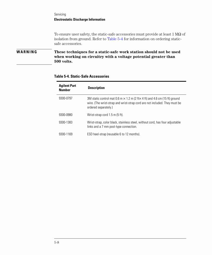
To ensure user safety, the static-safe accessories must provide at least 1 MΩ of isolation from ground. Refer to Table 5-4 for information on ordering static-safe accessories.
W A R N I N G These techniques for a static-safe work station should not be used
when working on circuitry with a voltage potential greater than
500 volts.
Table 5-4. Static-Safe Accessories
Agilent Part Number
Description
9300-0797 3M static control mat 0.6 m × 1.2 m (2 ft× 4 ft) and 4.6 cm (15 ft) ground wire. (The wrist-strap and wrist-strap cord are not included. They must be ordered separately.)
9300-0980 Wrist-strap cord 1.5 m (5 ft).
9300-1383 Wrist-strap, color black, stainless steel, without cord, has four adjustable links and a 7 mm post-type connection.
9300-1169 ESD heel-strap (reusable 6 to 12 months).
5-8
ServicingTroubleshooting
Troubleshooting
The following procedures are located in this section:
If the output power is low 5-10To check the line-power fuse 5-11
W A R N I N G The opening of covers or removal of parts is likely to expose
dangerous voltages. Disconnect the instrument from all voltage
sources while it is being opened.
W A R N I N G The power cord is connected to internal capacitors that may remain
live for five seconds after disconnecting the plug from its power
supply.
5-9
ServicingTroubleshooting
If the output power is low
Check for the following common problems:
Clean the OPTICAL OUT connector as described in “Cleaning Connections for Ac-curate Measurements” on page 2-9.
Perform the adjustment procedures.
5-10
ServicingTroubleshooting
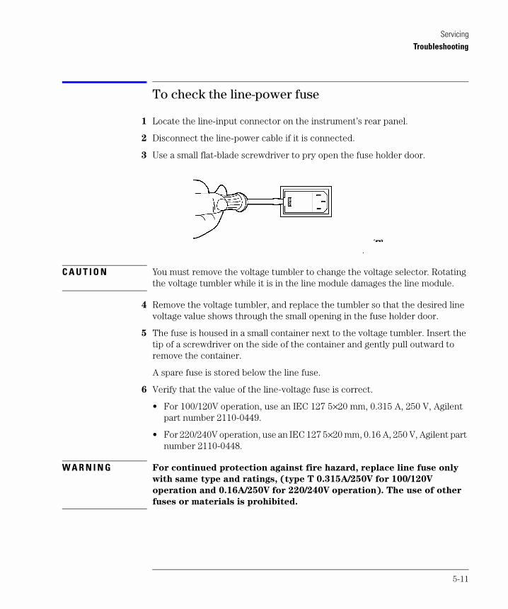
To check the line-power fuse
1 Locate the line-input connector on the instrument’s rear panel.
2 Disconnect the line-power cable if it is connected.
3 Use a small flat-blade screwdriver to pry open the fuse holder door.
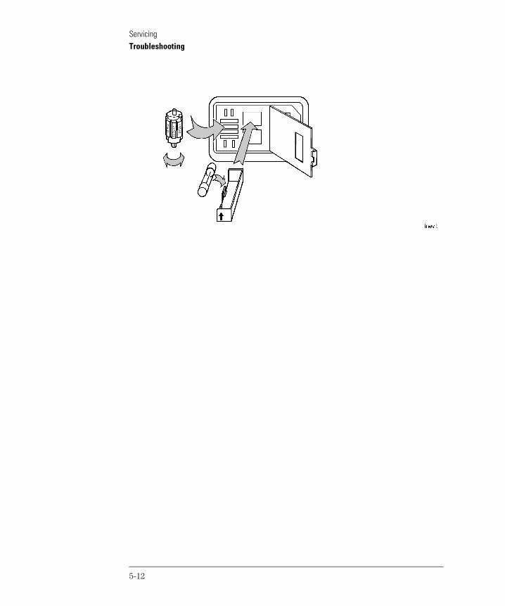
C A U T I O N You must remove the voltage tumbler to change the voltage selector. Rotating the voltage tumbler while it is in the line module damages the line module.
4 Remove the voltage tumbler, and replace the tumbler so that the desired line voltage value shows through the small opening in the fuse holder door.
5 The fuse is housed in a small container next to the voltage tumbler. Insert the tip of a screwdriver on the side of the container and gently pull outward to remove the container.
A spare fuse is stored below the line fuse.
6 Verify that the value of the line-voltage fuse is correct.
• For 100/120V operation, use an IEC 127 5×20 mm, 0.315 A, 250 V, Agilent part number 2110-0449.
• For 220/240V operation, use an IEC 127 5×20 mm, 0.16 A, 250 V, Agilent part number 2110-0448.
W A R N I N G For continued protection against fire hazard, replace line fuse only
with same type and ratings, (type T 0.315A/250V for 100/120V
operation and 0.16A/250V for 220/240V operation). The use of other
fuses or materials is prohibited.
5-11
ServicingTroubleshooting
5-12
ServicingPerformance Tests
Performance Tests
The procedures in this section test the Agilent 83430A’s performance using the specifications listed in Chapter 3, “Specifications and Regulatory Informa-tion” as the performance standard. All of the tests are done manually without the aid of a computer. None of these tests require access to the interior of the instrument. Allow the Agilent 83430A to warm up for 15 minutes before doing any of the performance tests.
If the instrument fails any performance test, perform the adjustment proce-dures located in “Adjustment Procedures” on page 5-36.
The following performance tests are included in this section:
Test 1. Digital Threshold 5-15Test 2. Frequency Response (ANALOG IN) 5-17Test 3. Electrical Return Loss (ANALOG IN) 5-20Test 4. Electrical Return Loss (DIGITAL IN) 5-22Test 5. Eye Quality (DIGITAL IN) 5-24Test 6. STM-16/OC-48 Conformance 5-26Test 7. OC-1 Conformance 5-28Test 8. Output Power 5-31Test 9. Output Wavelength 5-33
Calibration Cycle
This instrument requires periodic verification of performance. The instrument should have a complete verification of specifications at least once every two years.
C A U T I O N Option 022 instruments have an angled-fiber output. Be sure to use an angled-fiber patchcord during testing. If you do not have an angled-fiber patchcord available, you can purchase the required accessories from Agilent Technologies. These include the Agilent 81000SI DIN connector interface and the Agilent 81113PC DIN 4108 (angled) to Super-PC patchcord.
5-13
ServicingPerformance Tests
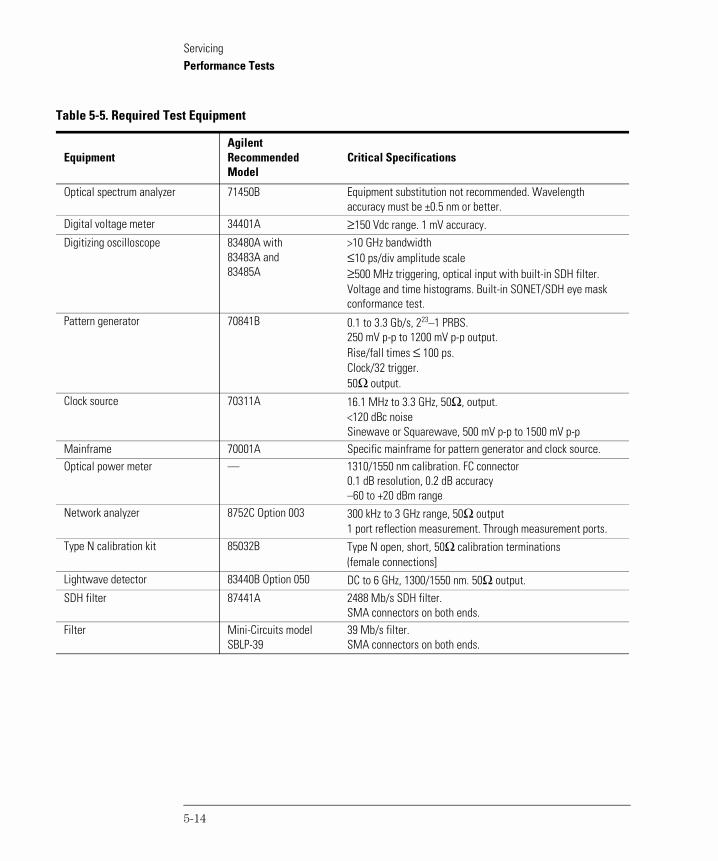
Table 5-5. Required Test Equipment
EquipmentAgilent RecommendedModel
Critical Specifications
Optical spectrum analyzer 71450B Equipment substitution not recommended. Wavelength accuracy must be ±0.5 nm or better.
Digital voltage meter 34401A ≥150 Vdc range. 1 mV accuracy.Digitizing oscilloscope 83480A with
83483A and 83485A
>10 GHz bandwidth≤10 ps/div amplitude scale≥500 MHz triggering, optical input with built-in SDH filter.Voltage and time histograms. Built-in SONET/SDH eye mask conformance test.
Pattern generator 70841B 0.1 to 3.3 Gb/s, 223–1 PRBS. 250 mV p-p to 1200 mV p-p output. Rise/fall times ≤ 100 ps. Clock/32 trigger. 50Ω output.
Clock source 70311A 16.1 MHz to 3.3 GHz, 50Ω, output.<120 dBc noiseSinewave or Squarewave, 500 mV p-p to 1500 mV p-p
Mainframe 70001A Specific mainframe for pattern generator and clock source.Optical power meter — 1310/1550 nm calibration. FC connector
0.1 dB resolution, 0.2 dB accuracy–60 to +20 dBm range
Network analyzer 8752C Option 003 300 kHz to 3 GHz range, 50Ω output1 port reflection measurement. Through measurement ports.
Type N calibration kit 85032B Type N open, short, 50Ω calibration terminations (female connections]
Lightwave detector 83440B Option 050 DC to 6 GHz, 1300/1550 nm. 50Ω output.SDH filter 87441A 2488 Mb/s SDH filter.
SMA connectors on both ends.Filter Mini-Circuits model
SBLP-3939 Mb/s filter.SMA connectors on both ends.
5-14
ServicingPerformance Tests
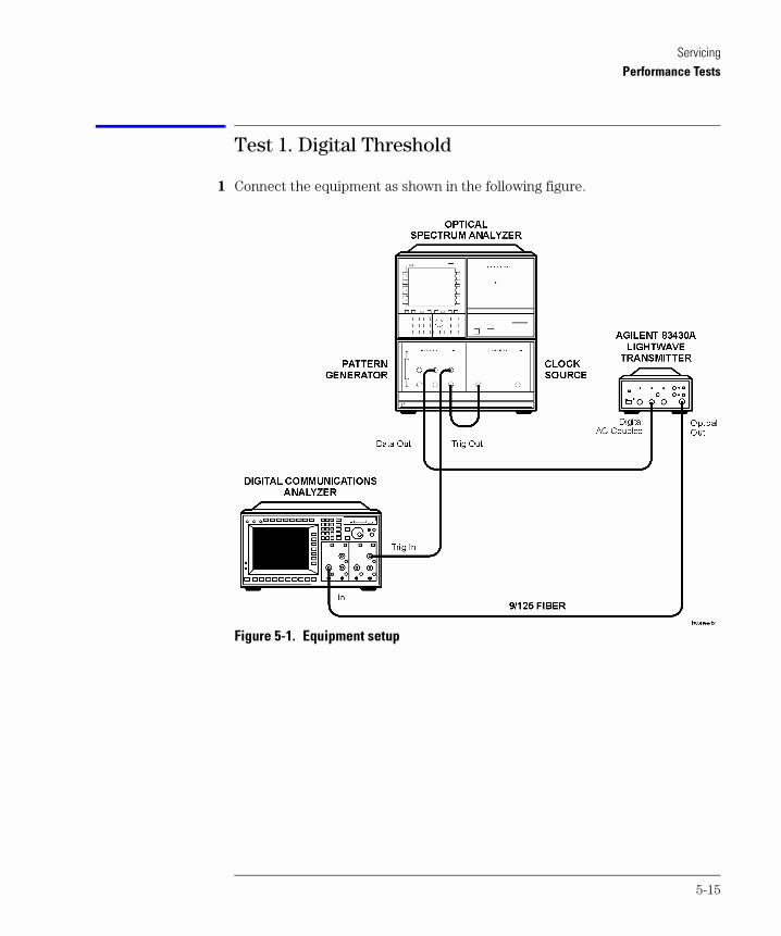
Test 1. Digital Threshold
1 Connect the equipment as shown in the following figure.
Figure 5-1. Equipment setup
5-15
ServicingPerformance Tests
2 Set the pattern generator to the following settings. For step-by-step instructions on setting these values, refer to “Configuring the pattern generator” on page 5-35.
data pattern. . . . . . . . . . . . . . . . . . . . . . . . . . . . . . . . . . . . . . . . . . . . . . . . . . 223–1data amplitude (ECL). . . . . . . . . . . . . . . . . . . . . . . . . . . . . . . . . . . . . 850 mV p-pdata output high level (ECL) . . . . . . . . . . . . . . . . . . . . . . . . . . . . . . . . . –900 mVdata termination . . . . . . . . . . . . . . . . . . . . . . . . . . . . . . . . . . . . . . . . . . . . . . . –2 Vtrigger mode . . . . . . . . . . . . . . . . . . . . . . . . . . . . . . . . . . . . . . . . . . . .CLOCK / 23trigger pattern. . . . . . . . . . . . . . . . . . . . . . . . . . . . . . . . . . . . . . . . . . . . . .23 zerosclock rate. . . . . . . . . . . . . . . . . . . . . . . . . . . . . . . . . . . . . . . . . . . . . . 2.48832 GHzclock amplitude. . . . . . . . . . . . . . . . . . . . . . . . . . . . . . . . . . . . . . . . . . . . . 850 mV
3 Press the Agilent 83430A’s front-panel SELECT key repeatedly until the DIGITAL IN AC COUPLED light is on.
4 While turning the Agilent 83430A’s front-panel DIGITAL THRESHOLD knob fully clockwise and fully counterclockwise, observe the following items:
• The eye is not squelched for any setting of the knob.
• The eye diagram’s zero crossing varies as the knob is turned.
• The eye diagram’s zero crossing should be approximately in the middle when the knob is set to its center position.
5 Disconnect the modulation signal from the DIGITAL IN AC COUPLED connector, and connect it to the DIGITAL IN DC COUPLED connector.
6 Press the Agilent 83430A’s front-panel SELECT key so that the DIGITAL IN DC COUPLED light is on.
7 While turning the Agilent 83430A’s front-panel DIGITAL THRESHOLD knob fully clockwise and fully counterclockwise, observe the following items:
• The eye is not squelched for any setting of the knob.
• The eye diagram’s zero crossing varies as the knob is turned.
5-16
ServicingPerformance Tests
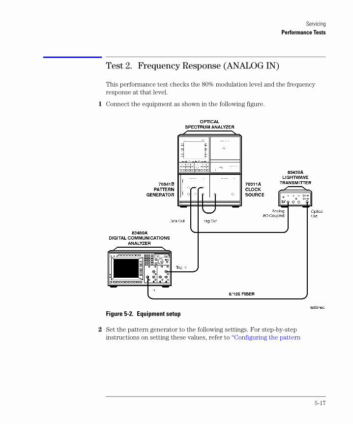
Test 2. Frequency Response (ANALOG IN)
This performance test checks the 80% modulation level and the frequency response at that level.
1 Connect the equipment as shown in the following figure.
Figure 5-2. Equipment setup
2 Set the pattern generator to the following settings. For step-by-step instructions on setting these values, refer to “Configuring the pattern
5-17
ServicingPerformance Tests
generator” on page 5-35.
data pattern. . . . . . . . . . . . . . . . . . . . . . . . . . . . . . . . . . . . . . . . . . . . . . . . . . 223–1data amplitude (ECL). . . . . . . . . . . . . . . . . . . . . . . . . . . . . . . . . . . . . 850 mV p-pdata output high level (ECL) . . . . . . . . . . . . . . . . . . . . . . . . . . . . . . . . . –900 mVdata termination . . . . . . . . . . . . . . . . . . . . . . . . . . . . . . . . . . . . . . . . . . . . . . . –2 Vtrigger mode . . . . . . . . . . . . . . . . . . . . . . . . . . . . . . . . . . . . . . . . . . . .CLOCK / 23trigger pattern. . . . . . . . . . . . . . . . . . . . . . . . . . . . . . . . . . . . . . . . . . . . . .23 zerosclock rate. . . . . . . . . . . . . . . . . . . . . . . . . . . . . . . . . . . . . . . . . . . . . . 2.48832 GHzclock amplitude. . . . . . . . . . . . . . . . . . . . . . . . . . . . . . . . . . . . . . . . . . . . . 850 mV
3 Press the Agilent 83430A’s front-panel SELECT key repeatedly until the ANALOG IN AC COUPLED light is on.
4 On the Agilent 83480A digital communications analyzer, perform the following tasks:
a Turn the optical channel on. All other channels should be turned off.
b Enable the internal OC-48 filter.
5 Connect the Agilent 83430A to the optical channel.
6 Disconnect the modulation input cable from the ANALOG IN AC COUPLED connector.
7 On the Agilent 83480A, position voltage cursor 1 to the displayed unmodulated level.
8 Turn the Agilent 83430A’s LINE switch off.
9 On the Agilent 83480A, position voltage cursor 2 to the displayed dark level voltage. Do not disconnect the fiber-optic cable until the 80% modulation index is measured.
10 Measure the voltage difference between the two cursors, multiply this value by 0.8, and position cursor 2 to where the difference equals this calculated value.
11 Turn the Agilent 83430A’s LINE switch on.
12 Reconnect the modulation input cable to the ANALOG IN AC COUPLED connector.
13 Increase the pattern generator’s data amplitude until the average (lower) peak of the eye reaches the level indicated by voltage cursor 2.
14 The data amplitude shown on the pattern generator’s display should be between 1.05 V p-p and 1.9 V p-p.
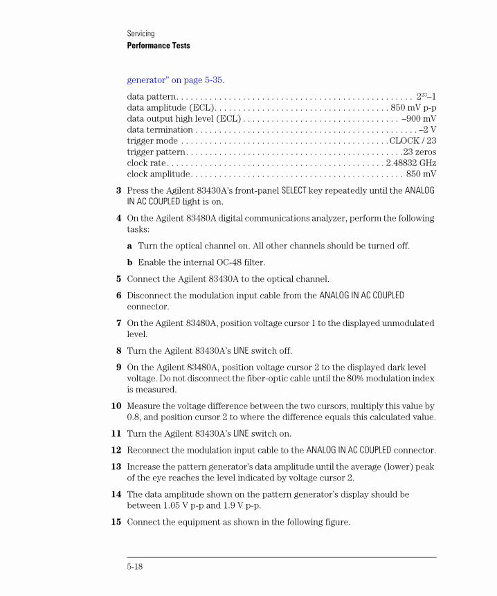
15 Connect the equipment as shown in the following figure.
5-18
ServicingPerformance Tests
Figure 5-3. Equipment setup
16 Press the PRESET key on the Agilent 8752C network analyzer.
17 Set the Agilent 8752C to the following settings:
RF output power . . . . . . . . . . . . . . . . . . . . . . . . . . . . . . . . . . . . . . . . . . . –10 dBmamplitude scale . . . . . . . . . . . . . . . . . . . . . . . . . . . . . . . . . . . . . . . . 3 dB/divisionstart frequency . . . . . . . . . . . . . . . . . . . . . . . . . . . . . . . . . . . . . . . . . . . . 0.3 MHzstop frequency . . . . . . . . . . . . . . . . . . . . . . . . . . . . . . . . . . . . . . . . . . . . 3000 MHzmarker 1 (reference marker) . . . . . . . . . . . . . . . . . . . . . . . . . . . . . . . . . 0.3 MHzaveraging . . . . . . . . . . . . . . . . . . . . . . . . . . . . . . . . . . . . . . . . . . . . . . . . . . . . . . onaveraging number . . . . . . . . . . . . . . . . . . . . . . . . . . . . . . . . . . . . . . . . . . . . . . . 16trace points . . . . . . . . . . . . . . . . . . . . . . . . . . . . . . . . . . . . . . . . . . . . . . . . . . . 801
18 Press the MEAS key on the Agilent 8752C. Then, press Transmissn. A through calibration is not required.
19 Verify that the –3 dB point is greater than 2.5 GHz.
5-19
ServicingPerformance Tests
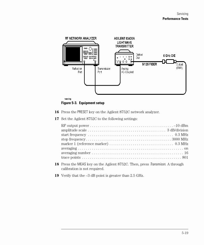
Test 3. Electrical Return Loss (ANALOG IN)
This procedure measures the electrical return loss for this connection when the drive level is less than the power required for 80% modulation.
1 Press the PRESET key on the Agilent 8752C network analyzer.
Figure 5-4. Calibration kit connections
2 With averaging on, calibrate the Agilent 8752C for a 1-port reflection measurement at the end of the RF output cable. Use the calibration termination kit. A through calibration is not required.
3 Connect the equipment as shown in the following figure.
Figure 5-5. Equipment setup
5-20
ServicingPerformance Tests
4 Set the Agilent 8752C to the following settings:
RF output power . . . . . . . . . . . . . . . . . . . . . . . . . . . . . . . . . . . . . . . . . . . –10 dBmamplitude scale . . . . . . . . . . . . . . . . . . . . . . . . . . . . . . . . . . . . . . . . 3 dB/divisionstart frequency . . . . . . . . . . . . . . . . . . . . . . . . . . . . . . . . . . . . . . . . . . . . 0.3 MHzstop frequency . . . . . . . . . . . . . . . . . . . . . . . . . . . . . . . . . . . . . . . . . . . . 3000 MHzmarker 1 (reference marker) . . . . . . . . . . . . . . . . . . . . . . . . . . . . . . . . . 0.3 MHzaveraging . . . . . . . . . . . . . . . . . . . . . . . . . . . . . . . . . . . . . . . . . . . . . . . . . . . . . . onaveraging number . . . . . . . . . . . . . . . . . . . . . . . . . . . . . . . . . . . . . . . . . . . . . . . 16trace points . . . . . . . . . . . . . . . . . . . . . . . . . . . . . . . . . . . . . . . . . . . . . . . . . . . 801
5 Press the Agilent 83430A’s front-panel SELECT key repeatedly until the ANALOG IN AC COUPLED light is on.
6 Press the MEAS key on the Agilent 8752C. Then, press Reflection.
7 Restart averaging on the Agilent 8752C.
8 Confirm that the return loss meets the following requirements:
≤ 1.0 GHz . . . . . . . . . . . . . . . . . . . . . . . . . . . . . . . . . . . . . . . . . . . . . . . .>12.07 dB1 GHz to 2 GHz . . . . . . . . . . . . . . . . . . . . . . . . . . . . . . . . . . . . . . . . . . . .>9.07 dB2 GHz to 2.5 GHz . . . . . . . . . . . . . . . . . . . . . . . . . . . . . . . . . . . . . . . . . . .>6.07 dB
5-21
ServicingPerformance Tests
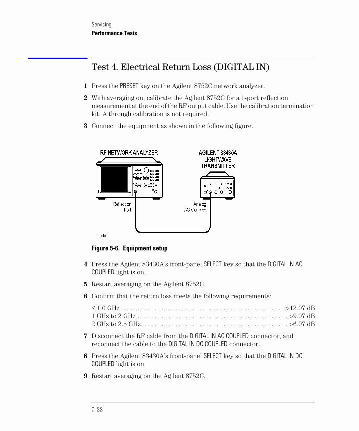
Test 4. Electrical Return Loss (DIGITAL IN)
1 Press the PRESET key on the Agilent 8752C network analyzer.
2 With averaging on, calibrate the Agilent 8752C for a 1-port reflection measurement at the end of the RF output cable. Use the calibration termination kit. A through calibration is not required.
3 Connect the equipment as shown in the following figure.
Figure 5-6. Equipment setup
4 Press the Agilent 83430A’s front-panel SELECT key so that the DIGITAL IN AC COUPLED light is on.
5 Restart averaging on the Agilent 8752C.
6 Confirm that the return loss meets the following requirements:
≤ 1.0 GHz . . . . . . . . . . . . . . . . . . . . . . . . . . . . . . . . . . . . . . . . . . . . . . . . >12.07 dB1 GHz to 2 GHz . . . . . . . . . . . . . . . . . . . . . . . . . . . . . . . . . . . . . . . . . . . . >9.07 dB2 GHz to 2.5 GHz. . . . . . . . . . . . . . . . . . . . . . . . . . . . . . . . . . . . . . . . . . . >6.07 dB
7 Disconnect the RF cable from the DIGITAL IN AC COUPLED connector, and reconnect the cable to the DIGITAL IN DC COUPLED connector.
8 Press the Agilent 83430A’s front-panel SELECT key so that the DIGITAL IN DC COUPLED light is on.
9 Restart averaging on the Agilent 8752C.
5-22
ServicingPerformance Tests
10 Confirm that the return loss meets the following requirements:
≤ 1.0 GHz . . . . . . . . . . . . . . . . . . . . . . . . . . . . . . . . . . . . . . . . . . . . . . . .>12.07 dB1 GHz to 2 GHz . . . . . . . . . . . . . . . . . . . . . . . . . . . . . . . . . . . . . . . . . . . .>9.07 dB2 GHz to 2.5 GHz . . . . . . . . . . . . . . . . . . . . . . . . . . . . . . . . . . . . . . . . . . .>6.07 dB
11 Disconnect the Agilent 8752C from the Agilent 83430A.
5-23
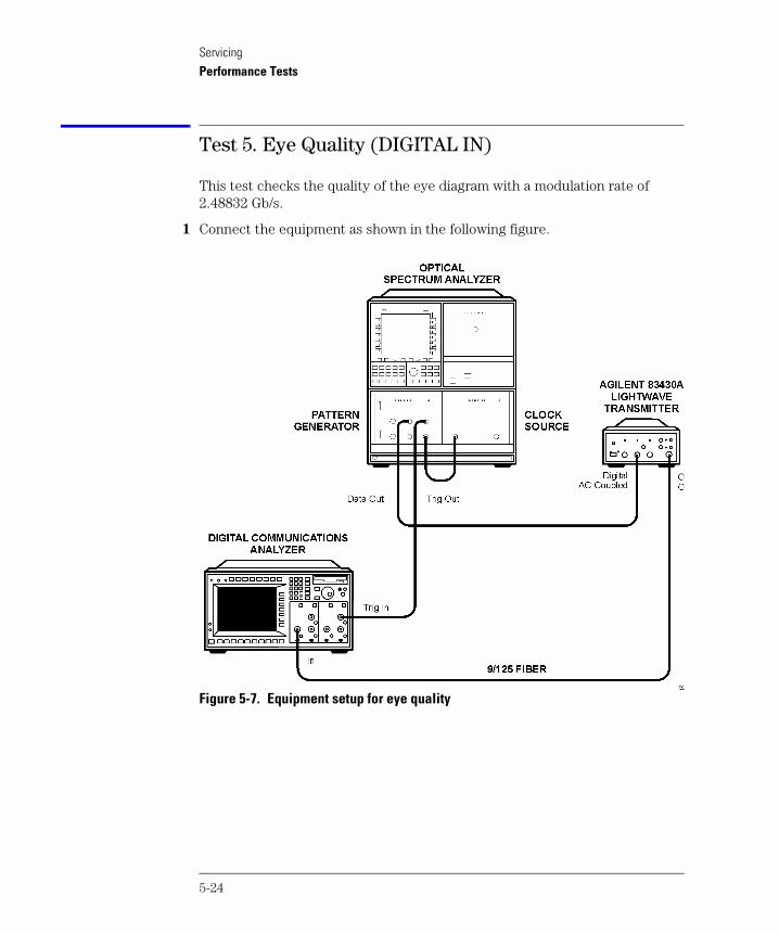
ServicingPerformance Tests
Test 5. Eye Quality (DIGITAL IN)
This test checks the quality of the eye diagram with a modulation rate of 2.48832 Gb/s.
1 Connect the equipment as shown in the following figure.
Figure 5-7. Equipment setup for eye quality
5-24
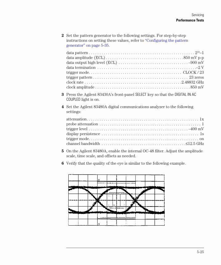
ServicingPerformance Tests
2 Set the pattern generator to the following settings. For step-by-step instructions on setting these values, refer to “Configuring the pattern generator” on page 5-35.
data pattern . . . . . . . . . . . . . . . . . . . . . . . . . . . . . . . . . . . . . . . . . . . . . . . . . . 223–1data amplitude (ECL) . . . . . . . . . . . . . . . . . . . . . . . . . . . . . . . . . . . . .850 mV p-pdata output high level (ECL) . . . . . . . . . . . . . . . . . . . . . . . . . . . . . . . . . –900 mVdata termination . . . . . . . . . . . . . . . . . . . . . . . . . . . . . . . . . . . . . . . . . . . . . . .–2 Vtrigger mode. . . . . . . . . . . . . . . . . . . . . . . . . . . . . . . . . . . . . . . . . . . . CLOCK / 23trigger pattern . . . . . . . . . . . . . . . . . . . . . . . . . . . . . . . . . . . . . . . . . . . . . 23 zerosclock rate . . . . . . . . . . . . . . . . . . . . . . . . . . . . . . . . . . . . . . . . . . . . . .2.48832 GHzclock amplitude . . . . . . . . . . . . . . . . . . . . . . . . . . . . . . . . . . . . . . . . . . . . . 850 mV
3 Press the Agilent 83430A’s front-panel SELECT key so that the DIGITAL IN AC COUPLED light is on.
4 Set the Agilent 83480A digital communications analyzer to the following settings:
attenuation. . . . . . . . . . . . . . . . . . . . . . . . . . . . . . . . . . . . . . . . . . . . . . . . . . . . . 1xprobe attenuation . . . . . . . . . . . . . . . . . . . . . . . . . . . . . . . . . . . . . . . . . . . . . . . . 1trigger level . . . . . . . . . . . . . . . . . . . . . . . . . . . . . . . . . . . . . . . . . . . . . . . –400 mVdisplay persistence . . . . . . . . . . . . . . . . . . . . . . . . . . . . . . . . . . . . . . . . . . . . . . 1strigger mode. . . . . . . . . . . . . . . . . . . . . . . . . . . . . . . . . . . . . . . . . . . . . . . . . . . . onchannel bandwidth . . . . . . . . . . . . . . . . . . . . . . . . . . . . . . . . . . . . . . . .≤12.5 GHz
5 On the Agilent 83480A, enable the internal OC-48 filter. Adjust the amplitude scale, time scale, and offsets as needed.
6 Verify that the quality of the eye is similar to the following example.
5-25
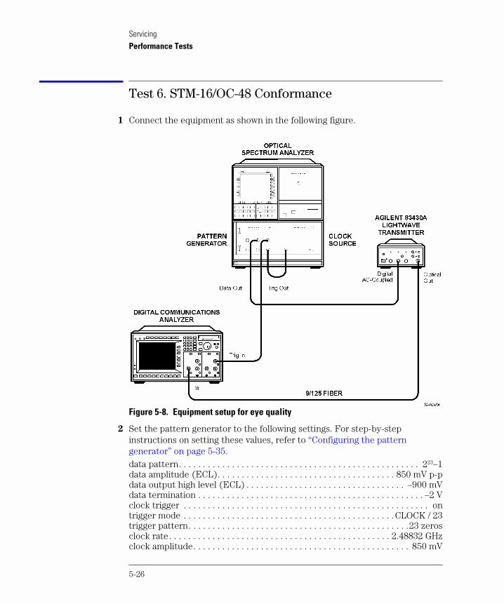
ServicingPerformance Tests
Test 6. STM-16/OC-48 Conformance
1 Connect the equipment as shown in the following figure.
Figure 5-8. Equipment setup for eye quality
2 Set the pattern generator to the following settings. For step-by-step instructions on setting these values, refer to “Configuring the pattern generator” on page 5-35.data pattern. . . . . . . . . . . . . . . . . . . . . . . . . . . . . . . . . . . . . . . . . . . . . . . . . . 223–1data amplitude (ECL). . . . . . . . . . . . . . . . . . . . . . . . . . . . . . . . . . . . . 850 mV p-pdata output high level (ECL) . . . . . . . . . . . . . . . . . . . . . . . . . . . . . . . . . –900 mVdata termination . . . . . . . . . . . . . . . . . . . . . . . . . . . . . . . . . . . . . . . . . . . . . . . –2 Vclock trigger . . . . . . . . . . . . . . . . . . . . . . . . . . . . . . . . . . . . . . . . . . . . . . . . . . . ontrigger mode . . . . . . . . . . . . . . . . . . . . . . . . . . . . . . . . . . . . . . . . . . . .CLOCK / 23trigger pattern. . . . . . . . . . . . . . . . . . . . . . . . . . . . . . . . . . . . . . . . . . . . . .23 zerosclock rate. . . . . . . . . . . . . . . . . . . . . . . . . . . . . . . . . . . . . . . . . . . . . . 2.48832 GHzclock amplitude. . . . . . . . . . . . . . . . . . . . . . . . . . . . . . . . . . . . . . . . . . . . . 850 mV
5-26
ServicingPerformance Tests
3 Turn the Agilent 83430A on, and press both front-panel PRESET/VARIABLE buttons so that the WAVELENGTH ADJUST and BIAS ADJUST lights are off.
4 On the Agilent 83480A digital communications analyzer, adjust the amplitude scale, time scale, and offsets as needed.
5 Adjust the Agilent 83430A’s front-panel DIGITAL THRESHOLD knob so that a zero crossing occurs at center screen (approximate 50% crossing).
6 On the Agilent 83480A, perform the following steps:
a Turn the optical channel on. Turn all other channels off.
b Enable the internal OC-48 filter.
c Press the blue shift key and then press MEAS EYE.
d Press Extinction ratio.
e Press Continue to activate the color grade.
f Press Dark cal, and follow the instructions on the screen.
g When the dark calibration is complete, press Format to select decibels.
h Press Enter to complete the measurement setup.
7 Clear the Agilent 83480A’s display, and allow adequate time for the extinction ratio measurement to settle.
8 The extinction ratio should measure greater than 9.0 dB.
9 On the Agilent 83480A, set the persistence to 1s and turn off the color grade.
10 Press the blue shift key and then press MASK TEST.
11 Press Mask Test On.
12 Press Create Mask and then Standard. Select the OC-48 mask.
13 Press Done.
14 Set the mask margin to 10%.
15 Press Mask Align to center the mask on the eye.
Repeat this step as needed if the vertical dashed lines do not occur at the cross-ing waist on either side of the eye.
16 Press Run Until, and wait for 300 waveforms to be processed.
17 Press the blue shift key and then press Eye mask to display the eye mask results. Verify that there are no mask or margin hits.
5-27
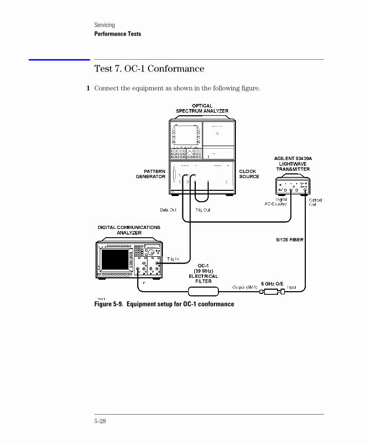
ServicingPerformance Tests
Test 7. OC-1 Conformance
1 Connect the equipment as shown in the following figure.
Figure 5-9. Equipment setup for OC-1 conformance
5-28
ServicingPerformance Tests
2 Set the pattern generator to the following settings. For step-by-step instructions on setting these values, refer to “Configuring the pattern generator” on page 5-35.
data pattern . . . . . . . . . . . . . . . . . . . . . . . . . . . . . . . . . . . . . . . . . . . . . . . . . . 223–1data amplitude (ECL) . . . . . . . . . . . . . . . . . . . . . . . . . . . . . . . . . . . . .850 mV p-pdata output high level (ECL) . . . . . . . . . . . . . . . . . . . . . . . . . . . . . . . . . –900 mVdata termination . . . . . . . . . . . . . . . . . . . . . . . . . . . . . . . . . . . . . . . . . . . . . . .–2 Vtrigger mode. . . . . . . . . . . . . . . . . . . . . . . . . . . . . . . . . . . . . . . . . . . . CLOCK / 23trigger pattern . . . . . . . . . . . . . . . . . . . . . . . . . . . . . . . . . . . . . . . . . . . . . 23 zerosclock rate . . . . . . . . . . . . . . . . . . . . . . . . . . . . . . . . . . . . . . . . . . . . . . . 51.84 MHzclock amplitude . . . . . . . . . . . . . . . . . . . . . . . . . . . . . . . . . . . . . . . . . . . . . 850 mV
3 On the Agilent 83480A digital communications analyzer, perform the following steps:
a Press the blue shift key and then press MEAS EYE.
b Press Extinction ratio.
c Press Continue to activate the color grade.
d Press Dark cal, and follow the instructions on the screen.
e When the dark calibration is complete, press Format to select decibels.
f Press Enter to complete the measurement setup.
4 Clear the Agilent 83480A’s display, and allow adequate time for the extinction ratio measurement to settle.
5 The extinction ratio should measure greater than 9.0 dB.
6 Turn off the Agilent 83480A’s color grade feature, and set the persistence to 1s.
7 On the Agilent 83480A, set the persistence to 1s.
8 Press the blue shift key and then press MASK TEST.
9 Press Mask Test On.
10 Press Create Mask and then Standard. Select the OC-1 mask.
11 Press Done.
12 Set the mask margin to 20%.
13 Press Mask Align to center the mask on the eye.
Repeat this step as needed if the vertical dashed lines do not occur at the cross-ing waist on either side of the eye.
5-29
ServicingPerformance Tests
14 Press Run Until, and wait for 300 waveforms to be processed.
15 Press the blue shift key and then press Eye mask to display the eye mask results.Verify that there are no mask or margin hits.
5-30
ServicingPerformance Tests
Test 8. Output Power
1 Connect the Agilent 83430A’s OPTICAL OUT connector to a optical power meter.
2 Disconnect any cables connected to the Agilent 83430A’s ANALOG IN or DIGITAL IN input connectors.
3 Turn the Agilent 83430A on, and press the front-panel PRESET/VARIABLE button so that the BIAS ADJUST light is off.
4 Press the Agilent 83430A’s front-panel SELECT key repeatedly until the DIGITAL IN DC COUPLED light is on.
5 Verify that the optical output power measures 10.0 dBm ±0.2 dB.
6 Press the front-panel PRESET/VARIABLE button so that the BIAS ADJUST light is on.
7 Turn the front-panel BIAS ADJUST knob fully clockwise.
8 Verify that the optical output power does not exceed –2.5 dBm.
9 Turn the front-panel BIAS ADJUST knob fully counterclockwise.
10 Connect the pattern generator’s output to the Agilent 83430A’s DIGITAL IN DC COUPLED input connector.
11 Configure the Agilent 70841B pattern generator to output an ECL logic level 1:
a Set the pattern generator to the following settings. For step-by-step instruc-tions on setting these values, refer to “Configuring the pattern generator” on page 5-35.
data pattern. . . . . . . . . . . . . . . . . . . . . . . . . . . . . . . . . . . . . . . . . . . . . . . . 223–1data amplitude (ECL). . . . . . . . . . . . . . . . . . . . . . . . . . . . . . . . . . .850 mV p-pdata output high level (ECL) . . . . . . . . . . . . . . . . . . . . . . . . . . . . . . . –900 mVdata termination . . . . . . . . . . . . . . . . . . . . . . . . . . . . . . . . . . . . . . . . . . . . .–2 Vtrigger mode . . . . . . . . . . . . . . . . . . . . . . . . . . . . . . . . . . . . . . . . . CLOCK / 23trigger pattern. . . . . . . . . . . . . . . . . . . . . . . . . . . . . . . . . . . . . . . . . . . 23 zerosclock rate . . . . . . . . . . . . . . . . . . . . . . . . . . . . . . . . . . . . . . . . . . . . . 51.84 MHzclock amplitude. . . . . . . . . . . . . . . . . . . . . . . . . . . . . . . . . . . . . . . . . . . 850 mV
b Press the left-side edit usr-pat softkey.
c Press CURRENT PATTERN, more 1 of 3, set pat length, enter the value 8, and then press ENTER.
d Press BIN HEX so that HEX is underlined.
e Press more 2 of 3 and then press the F softkey twice.
5-31
ServicingPerformance Tests
f Press more 3 of 3, more 1 of 3, and then set pat label.
g Use the displayed softkeys to create a label to identify this new pattern. It will minimize confusion as you use the pattern generator. Enter the suggest-ed label ALL ONES. Press FINISH ENTRY when you have finished entering all the letters in the label.
h Press more 2 of 3, more 3 of 3, save pattern, and then INTERNL PATT 1.
i Press the left-side select pattern softkey.
j Press user pattern and then INTERNL PATT 1.
12 Set the BIAS ADJUST potentiometer fully clockwise, then verify that the optical output power does not exceed +2.5 dBm.
13 Remove the cable from the DIGITAL IN DC COUPLED input connector.
14 Press the Agilent 83430A’s front-panel SELECT key repeatedly until the ANALOG IN AC COUPLED light is on.
15 Make sure that the front-panel BIAS ADJUST knob is fully clockwise.
16 Verify that the optical output power does not exceed +0.5 dBm.
17 Turn the BIAS ADJUST knob fully counterclockwise.
18 The optical power should measure between –2.0 dBm and –5.0 dBm.
5-32
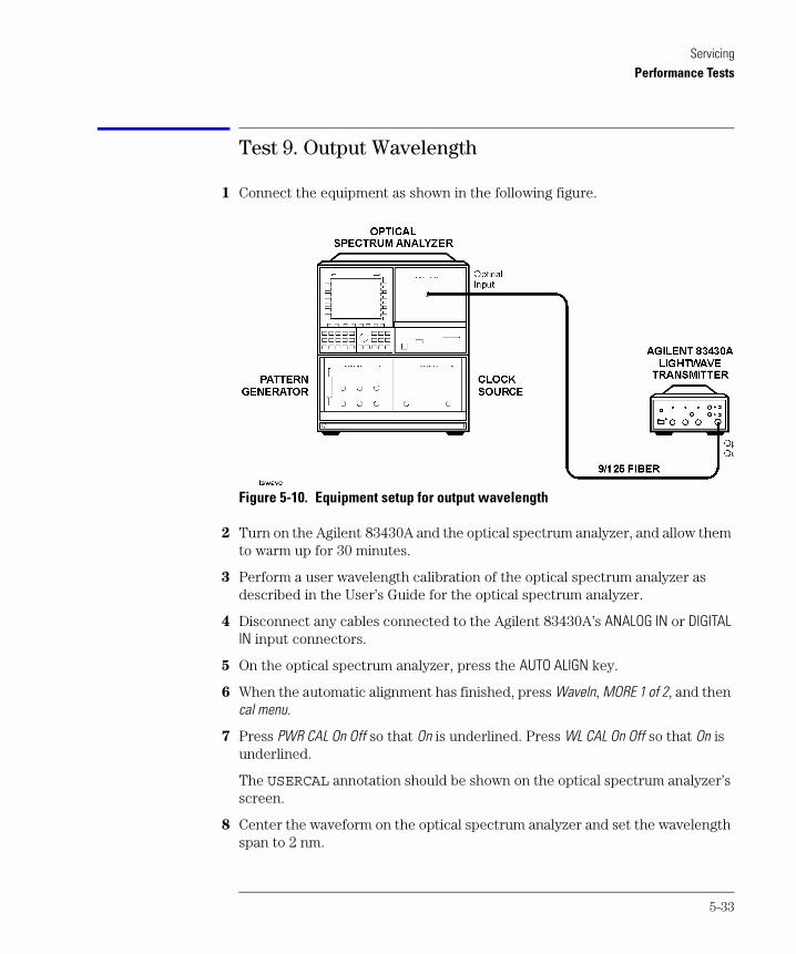
ServicingPerformance Tests
Test 9. Output Wavelength
1 Connect the equipment as shown in the following figure.
Figure 5-10. Equipment setup for output wavelength
2 Turn on the Agilent 83430A and the optical spectrum analyzer, and allow them to warm up for 30 minutes.
3 Perform a user wavelength calibration of the optical spectrum analyzer as described in the User’s Guide for the optical spectrum analyzer.
4 Disconnect any cables connected to the Agilent 83430A’s ANALOG IN or DIGITAL IN input connectors.
5 On the optical spectrum analyzer, press the AUTO ALIGN key.
6 When the automatic alignment has finished, press Waveln, MORE 1 of 2, and then cal menu.
7 Press PWR CAL On Off so that On is underlined. Press WL CAL On Off so that On is underlined.
The USERCAL annotation should be shown on the optical spectrum analyzer’s screen.
8 Center the waveform on the optical spectrum analyzer and set the wavelength span to 2 nm.
5-33
ServicingPerformance Tests
9 Verify that the measured wavelength is within 1 nm of the Agilent 83430A’s nominal value.
If the Agilent 83430A is an Option 130, the wavelength must be within 20 nm of the nominal value.
5-34
ServicingPerformance Tests
Configuring the pattern generator
This procedure shows you, step-by-step, how to configure the Agilent 70841B pattern generator settings for the performance tests and adjustment proce-dures. It is assumed, that the Agilent 70311A clock source is configured in the modular measurement system (MMS) mainframe as a slave to the pattern gen-erator module. This allows you to change the clock source’s frequency from the pattern generator. If your clock source is not configured as a slave module to the pattern generator, you can still set its frequency using its own menu. Consult the user manuals for these products to learn how to correctly install and operate them.
1 Turn on the MMS system, and display the menu for the pattern generator.
2 Press the green INSTR PRESET key.
3 Press the left-side select pattern softkey.
4 Press the 2 23–1 softkey.
5 Press the left-side trg o/p clk o/p softkey.
6 Press TRIGGER PAT CLK so that CLK is underlined.
This sets the trigger mode.
7 Press CLOCK FREQ, and enter the clock frequency.
8 Press CLOCK AMPLTD, and enter the clock amplitude.
9 Press the left-side dat o/p err-add softkey, more 2 of 2, and then DAT TRM 0V –2V, so that –2V is underlined.
This sets the data termination level.
10 Press more 2 of 2 and then DATA ECL.
5-35
ServicingAdjustment Procedures
Adjustment Procedures
Perform the adjustments in this section if the instrument fails any of its per-formance tests. Periodic adjustment is not required to maintain safety.
The following adjustment procedures are provided in this section:
To remove the instrument cover 5-38Adjustment 1. Power Supply 5-39Adjustment 2. Laser Bias and Control 5-41
W A R N I N G Improper internal adjustments may change the laser classification of
this instrument. Always perform the adjustments exactly as described
in this section.
C A U T I O N Option 022 instruments have an angled-fiber output. Be sure to use an angled-fiber patchcord during testing. If you do not have an angled-fiber patchcord available, you can purchase the required accessories from Agilent Technologies. These include the Agilent 81000SI DIN connector interface and the Agilent 81113PC DIN 4108 (angled) to Super-PC patchcord.
W A R N I N G Do not remove or relocate any shunt jumpers located on any printed
circuit assembly.
5-36
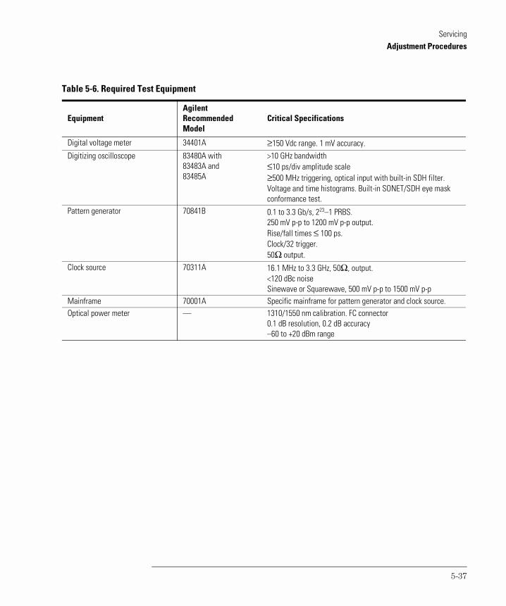
ServicingAdjustment Procedures
Table 5-6. Required Test Equipment
EquipmentAgilent RecommendedModel
Critical Specifications
Digital voltage meter 34401A ≥150 Vdc range. 1 mV accuracy.Digitizing oscilloscope 83480A with
83483A and 83485A
>10 GHz bandwidth≤10 ps/div amplitude scale≥500 MHz triggering, optical input with built-in SDH filter.Voltage and time histograms. Built-in SONET/SDH eye mask conformance test.
Pattern generator 70841B 0.1 to 3.3 Gb/s, 223–1 PRBS. 250 mV p-p to 1200 mV p-p output. Rise/fall times ≤ 100 ps. Clock/32 trigger. 50Ω output.
Clock source 70311A 16.1 MHz to 3.3 GHz, 50Ω, output.<120 dBc noiseSinewave or Squarewave, 500 mV p-p to 1500 mV p-p
Mainframe 70001A Specific mainframe for pattern generator and clock source.Optical power meter — 1310/1550 nm calibration. FC connector
0.1 dB resolution, 0.2 dB accuracy–60 to +20 dBm range
5-37
ServicingAdjustment Procedures
To remove the instrument cover
C A U T I O N Electrostatic discharge (ESD) can damage or destroy electronic components. All work on electronic assemblies should be performed at a static-safe work station. Refer to “Electrostatic Discharge Information” on page 5-7 for more information on preventing ESD.
1 Disconnect the power cord from the instrument.
2 Position the instrument so that you are looking at the rear panel.
3 Use a T-15 TORX driver to back out the screw that attaches the top cover to the instrument.
Note that the screw is permanently secured to the cover.
4 After the screw is backed out, slide the cover toward the rear of the instrument approximately 4 mm. Then, lift the cover off the instrument.
5-38
ServicingAdjustment Procedures
Adjustment 1. Power Supply
In this procedure, you’ll adjust both the –12V and +12V supplies. These sup-plies are located on the A3 Power Supply Assembly. Because the +5V ADJ potentiometer is not used in this instrument, it is not adjusted.
1 Connect the line-power cord to the Agilent 83430A’s rear panel connector.
2 Turn on the Agilent 83430A.
3 Measure the dc voltage between the –OUT (violet wire) and +OUT (black wire) terminals located on the A3 assembly. Adjust the –12V ADJ potentiometer so that the voltage measures between –5.15 Vdc and –5.20 Vdc.
4 Measure the dc voltage between the +OUT (red wire) and COM (black wire) terminals. Adjust the +12V ADJ potentiometer so that the voltage measures between +11.8 Vdc and +12.0 Vdc.
5 If any of the potentiometer were adjusted in this procedure, you must perform the steps in “Adjustment 2. Laser Bias and Control” on page 5-41.
5-39
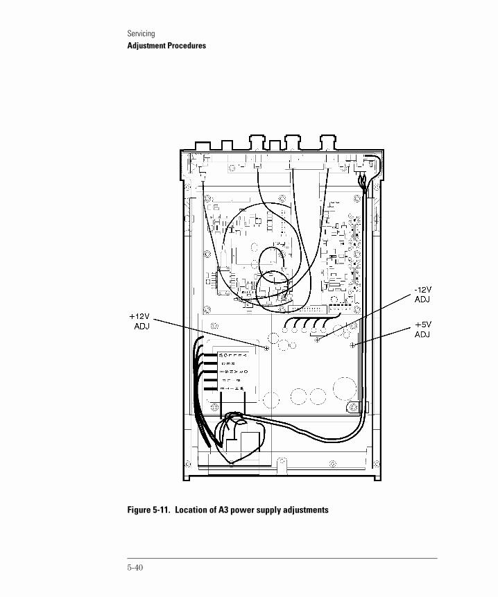
ServicingAdjustment Procedures
Figure 5-11. Location of A3 power supply adjustments
5-40
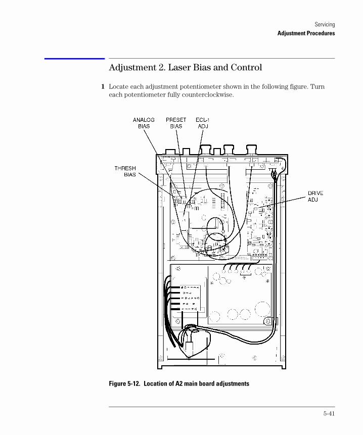
ServicingAdjustment Procedures
Adjustment 2. Laser Bias and Control
1 Locate each adjustment potentiometer shown in the following figure. Turn each potentiometer fully counterclockwise.
Figure 5-12. Location of A2 main board adjustments
5-41
ServicingAdjustment Procedures
2 Connect an optical power meter to the Agilent 83430A’s front-panel OPTICAL OUT connector. Use a good quality optical fiber (9/125 µm) and make sure the fiber is clean before connecting.
3 Turn the Agilent 83430A on, and press both front-panel PRESET/VARIABLE buttons so that the WAVELENGTH ADJUST and BIAS ADJUST lights are off.
4 Press the SELECT key repeatedly until the DIGITAL IN DC COUPLED light is on.
5 Adjust the THRESH BIAS potentiometer so that the output power measures –10.0 ±0.2 dBm.
6 Connect the output of the pattern generator to the Agilent 83430A’s front-panel DIGITAL IN DC COUPLED connector.
7 Configure the Agilent 70841B pattern generator to output an ECL logic level 1:
a Set the pattern generator to the following settings. For step-by-step instruc-tions on setting these values, refer to “Configuring the pattern generator” on page 5-35.
data pattern . . . . . . . . . . . . . . . . . . . . . . . . . . . . . . . . . . . . . . . . . . . . . . . 223–1data amplitude (ECL) . . . . . . . . . . . . . . . . . . . . . . . . . . . . . . . . . . 850 mV p-pdata output high level (ECL). . . . . . . . . . . . . . . . . . . . . . . . . . . . . . . –900 mVdata termination. . . . . . . . . . . . . . . . . . . . . . . . . . . . . . . . . . . . . . . . . . . . . –2 Vtrigger mode . . . . . . . . . . . . . . . . . . . . . . . . . . . . . . . . . . . . . . . . . .CLOCK / 23trigger pattern . . . . . . . . . . . . . . . . . . . . . . . . . . . . . . . . . . . . . . . . . . .23 zerosclock rate . . . . . . . . . . . . . . . . . . . . . . . . . . . . . . . . . . . . . . . . . . . . . 51.84 MHzclock amplitude . . . . . . . . . . . . . . . . . . . . . . . . . . . . . . . . . . . . . . . . . . 850 mV
b Press the left-side edit usr-pat softkey.
c Press CURRENT PATTERN, more 1 of 3, set pat length, enter the value 8, and then press ENTER.
d Press BIN HEX so that HEX is underlined.
e Press more 2 of 3 and then press the F softkey twice.
f Press more 3 of 3, more 1 of 3, and then set pat label.
g Use the displayed softkeys to create a label to identify this new pattern. It will minimize confusion as you use the pattern generator. Enter the suggest-ed label ALL ONES. Press FINISH ENTRY when you have finished entering all the letters in the label.
h Press more 2 of 3, more 3 of 3, save pattern, and then INTERNL PATT 1.
i Press the left-side select pattern softkey.
5-42
ServicingAdjustment Procedures
j Press user pattern and then INTERNL PATT 1.
8 Adjust the ECL –1 ADJ potentiometer so that the optical power measures +1.5 dBm.
9 On the pattern generator, press the left-side select pattern softkey.
10 Press the 2 23–1 softkey.
11 Locate the test points that are labeled “P4” on the A2 Main Board Assembly. Measure the voltage across pins 15 and 16 (LOOP test points).
12 Adjust the DRIVE ADJ potentiometer so that the voltage measured across pins 15 and 16 varies less than 20 mV when the pattern generator signal is present and then removed.
13 Disconnect the pattern generator signal from the Agilent 83430A.
14 Press the front-panel SELECT key so that the ANALOG IN AC COUPLED connector is selected. No signal should be connected to this input.
15 Adjust the ANALOG BIAS potentiometer so that the optical power measured at the front-panel OPTICAL OUT connector is –1.5 dBm ±0.2 dB.
16 Turn the Agilent 83430A’s LINE switch off.
5-43
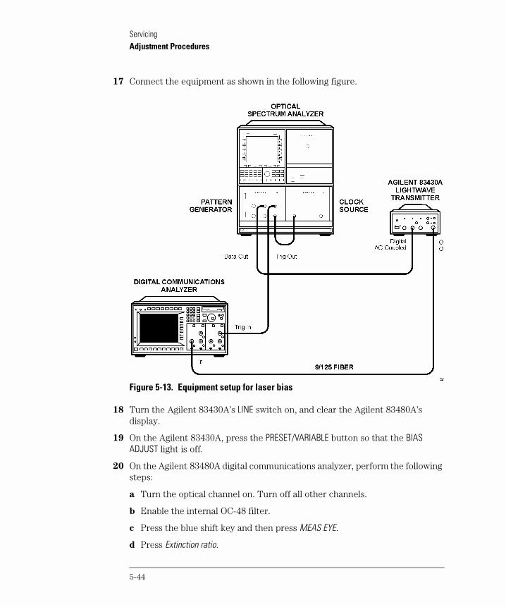
ServicingAdjustment Procedures
17 Connect the equipment as shown in the following figure.
Figure 5-13. Equipment setup for laser bias
18 Turn the Agilent 83430A’s LINE switch on, and clear the Agilent 83480A’s display.
19 On the Agilent 83430A, press the PRESET/VARIABLE button so that the BIAS ADJUST light is off.
20 On the Agilent 83480A digital communications analyzer, perform the following steps:
a Turn the optical channel on. Turn off all other channels.
b Enable the internal OC-48 filter.
c Press the blue shift key and then press MEAS EYE.
d Press Extinction ratio.
5-44
ServicingAdjustment Procedures
e Press Continue to activate the color grade.
f Press Dark cal, and follow the instructions on the screen.
g When the dark calibration is complete, press Format to select decibels.
h Press Enter to complete the measurement setup.
21 On the Agilent 83430A, press the front-panel PRESET/VARIABLE button so that the BIAS ADJUST light is on.
22 Turn the Agilent 83430A’s front-panel BIAS ADJUST knob fully clockwise.
23 Adjust the PRESET BIAS potentiometer so that the extinction ratio measures between 6.0 dB and 8.0 dB.
Between adjustments, be sure to clear the Agilent 83480A’s display and allow adequate time for the extinction ratio measurement to settle.
24 Turn the Agilent 83430A’s front-panel BIAS ADJUST knob fully counterclockwise.
25 Readjust the PRESET BIAS potentiometer so that the extinction ratio measures slightly greater than 13.5 dB.
26 Turn the Agilent 83430A’s front-panel BIAS ADJUST knob fully clockwise.
27 The minimum extinction ratio should measure less than 8.0 dB.
5-45

Index
AAC COUPLED connector, 2-3ac power cables, 1-9, 4-5accessories
static-safe, 5-8accuracy, measurement, ivadapters, 2-4
fiber optic, 4-4adjustable features, iiiadjusting
output amplitude, 2-4wavelength, 2-4
adjustment procedures, 5-36instrument cover removal, 5-38laser bias and control, 5-41power supply, 5-39required test equipment, 5-37
adjustment rangebias/extinction ratio, 3-4wavelength, 3-4
Agilent offices, 4-6amplitude, adjusting output, 2-4ANALOG IN connector, 2-3
electrical return loss performance test, 5-20frequency response performance test, 5-17specifications, 3-5
analog mode, average coupled power, 3-4angled output fiber, 4-3, 5-13, 5-36assemblies, instrument, 5-5average coupled power, specification, 3-4
BBIAS ADJUST knob, 2-4bias ratio adjustment range, 3-4BNC connector, 2-3
Ccabinet, cleaning, vi, 1-2, 5-4cables, 5-5
line power, 4-5calibration
cycle, 3-2, 5-13kit connections, 5-20termination kit, 5-20, 5-22
capabilities of system, ivcare
of cabinet, vi, 1-2, 5-4of fiber optics, iv
center wavelength specifications, 3-3classification
laser, v, 3-6product, vi, 1-2
cleaningadapters, 2-18cabinet, vi, 1-2fiber-optic connections, 2-9, 2-17non-lensed connectors, 2-17
compressed dust remover, 2-16configuring the pattern generator, 5-35connection, calibration kit, 5-20connector
care, 2-9input, 2-3specifications, 3-5
cotton swabs, 2-16creating a label, 5-32, 5-42
Ddamaged shipment, 1-4data amplitude, 5-18data termination level, setting, 5-35DC COUPLED connector, 2-3declaration of conformity, 3-7DIGITAL IN connector, 2-3
electrical return loss performance test, 5-22eye quality performance test, 5-24specifictions, 3-5
digital input threshold, iiidigital mode, peak coupled power, 3-4DIGITAL THRESHOLD knob, 2-3digital threshold, performance test, 5-15dimensions of instrument, 3-5dispersion power penalty, 3-4
testing, 2-7dust caps, 2-17
EECL
input, 2-3logic level, 5-31, 5-42
electrical return lossANALOG IN performance test, 5-20
Index-1
Index
DIGITAL IN performance test, 5-22ESD (electrostatic discharge), 5-4, 5-7, 5-38extinction ratio
adjustment range, 3-4measurement, 5-27, 5-29, 5-45optical signals, iiispecification, 3-4
eye diagramperformance test, 5-24zero crossing, 5-16
eye mask measurement, 5-30eye quality, 5-26
DIGITAL IN performance test, 5-24
Ffeatures, user adjustable, iiifiber optics
adapters, 2-4, 4-4, 5-18care of, ivcleaning connections, 2-9connectors, covering, 1-12
filter, OC-48, 5-18foam swabs, 2-16frequency level, checking, 5-17frequency response (ANALOG IN)
performance test, 5-17front panel
adapters, 4-4functions, 2-3
fuse, 1-6checking, 5-11spare, 5-11values, vi, 5-11
Ggeneral specifications, 3-4
Hhumidity, 3-5
IIEC Publication 61010-1, viinput
connector, 2-3, 2-9
ECL, 2-3modulation specifications, 3-5
inspectinginstrument, 1-4
installing, 1-2instrument
cover, removing, 5-38options, 4-3returning for service, 1-11serial number, 1-4
internal labels, 5-4
Jjitter generation, 3-4jitter tolerance, testing, 2-8
Llabels
creating, 5-32, 5-42internal, 5-4rear panel, 1-4
laseraperture, vclassification, v, 3-6, 5-4, 5-36
laser bias and controladjustment procedure, 5-41
line fuse, safety, 1-7LINE key, 1-10, 2-3line-power
cable, 1-8, 4-5cables, 4-5input connector, 1-6, 5-11requirements, 1-8specifications, 3-5
low output power, 5-10
Mmanual performance tests, 5-13measurement accuracy, 1-3modulation
checking level, 5-17input, 2-3
Index-2
Index
Nnoise declaration, 3-6noise, relative intensity, 3-4
OOC-1 conformance
performance test, 5-28OC-48 filter, 5-18, 5-25, 5-44OC-48/STM-16 conformance
performance test, 5-26one-port reflection measurement, 5-20, 5-22operating specifications, 3-5optical level symmetry, iiiOPTICAL OUT connector, iv–v, 1-3, 5-10optical output power
level, 5-32measurement, 5-31
optical receiver sensitivity, 2-5optical signal, extinction ratio, iiioptions, 4-3output amplitude, adjusting, 2-4output power performance test, 5-31output wavelength performance test, 5-33
Ppackaging for shipment, 1-12parts
major assemblies, 5-5pattern generator, configuring, 5-35peak coupled power, specification, 3-4performance tests, 5-13
adjustment procedures, 5-36configuring the pattern generator, 5-35digital threshold, 5-15electrical return loss (ANALOG IN), 5-20electrical return loss (DIGITAL IN), 5-22eye quality (DIGITAL IN), 5-24frequency response (ANALOG IN), 5-17OC-1 conformance, 5-28output power, 5-31output wavelength, 5-33required test equipment, 5-14STM-16/OC-48 conformance, 5-26
performance verification, 5-13power cable requirements, 1-8power supply adjustment procedure, 5-39
preset wavelength, 2-4PRESET/VARIABLE, 2-4
Rrack mounting requirements, 1-2radiation exposure, v, 5-3rear panel
label, 1-4voltage selector, 1-6
receiver sensitivity, optical, 2-5regulatory
duration, 3-2information, 3-6
relative intensity noise, 3-4removing the instrument cover, 5-38replacement procedures
instrument cover, 5-38required test equipment
adjustment procedures, 5-37performance tests, 5-14
return lossperformance test, 5-20
returning for service, 1-11
Ssafety, v, vi, 1-2, 5-2, 5-9, 5-36
laser classification, vi, 1-2line fuse, 1-7
sales and service offices, 4-6SDH/SONET
compliance, iiipattern, 3-4
SELECT key, 2-3selecting a wavelength, iiisensitivity, testing, 2-5serial number, instrument, 1-4service, 1-11
returning for, 1-11sales and service offices, 4-6tools, 5-5
setting the data termination level, 5-35setting the trigger mode, 5-35shipping
damage, 1-4procedure, 1-11
shunt jumpers, 5-36
Index-3
Index
side-mode suppression ratio, 3-4spare fuse, 1-6, 5-11specifications
center wavelength, 3-3definition of terms, 3-2general, 3-4operating, 3-5
spectral width, 3-4static-safe accessories, 5-8STM-16/OC-48 conformance
performance test, 5-26storage temperature, 3-5suppression ratio, side-mode, 3-4swabs, 2-16system test capabilities, iv
Ttest capabilities of system, ivtest equipment
adjustment procedures, 5-37performance tests, 5-14
threshold, digital input, iiitools for servicing, 5-4trigger mode, setting, 5-35troubleshooting, 5-2
check line-power fuse, 5-11low output power, 5-10
Uuser-adjustable features, iii
Vventilation requirements, 1-2verification of performance, 5-13voltage selector, 1-6
Wwavelength
adjustment, 2-4adjustment range, 3-4output performance test, 5-33selection, iii
WAVELENGTH ADJUST knob, 2-4weight, 3-5
wide-band jitter, measuring, 2-8
Zzero crossing, eye diagram, 5-16
Index-4