Embed Size (px)
Citation preview

The Agilent Technologies 34970A combines precision measurementcapability with flexible signal connections for your production anddevelopment test systems. Three module slots are built into the rear of the instrument to accept any combination of data acquisition orswitching modules. The combination of data logging and dataacquisition features makes this instrument a versatile solution for yourtesting requirements now and in the future.
Convenient Data Logging Features
• Direct measurement of thermocouples, RTDs, thermistors, dc voltage,ac voltage, resistance, dc current, ac current, frequency, and period
• Interval scanning with storage of up to 50,000 time-stamped readings
• Independent channel configuration with function, Mx+B scaling,and alarm limits available on a per-channel basis
• Intuitive user interface with knob for quick channel selection,menu navigation, and data entry from the front panel
• Portable, ruggedized case with non-skid feet
• BenchLink Data Logger Software for Microsoft ® Windows ® included
Flexible Data Acquisition / Switching Features
• 61⁄2-digit multimeter accuracy, stability, and noise rejection
• Up to 60 channels per instrument (120 single-ended channels)
• Reading rates up to 600 readings per second on a single channel andscan rates up to 250 channels per second
• Choice of multiplexing, matrix, general-purpose Form C switching,RF switching, digital I/O, totalize, and 16-bit analog output functions
• GPIB (IEEE-488) interface and RS-232 interface are standard
• SCPI (Standard Commands for Programmable Instruments) compatibility
Agilent 34970AData Acquisition / Switch Unit
Note: Unless otherwise indicated, this manual applies to all serial numbers.
Page 1 (User’s Guide)

The Front Panel at a Glance
1 State Storage / Remote Interface Menus2 Scan Start / Stop Key3 Measurement Configuration Menu4 Scaling Configuration Menu5 Alarm / Alarm Output Configuration Menu6 Scan-to-Scan Interval Menu7 Scan List Single Step / Read Key
8 Advanced Measurement / Utility Menus 9 Low-Level Module Control Keys10 Single-Channel Monitor On / Off Key11 View Scanned Data, Alarms, Errors Menu12 Shift / Local Key13 Knob14 Navigation Arrow Keys
Denotes a menu key. See the next page for details on menu operation.
2

The Rear Panel at a Glance
WARNINGFor protection from electrical shock, the power cord ground must not bedefeated. If only a two-contact electrical outlet is available, connect theinstrument’s chassis ground screw (see above) to a good earth ground.
1 Slot Identifier (100, 200, 300)2 Ext Trig Input / Alarm Outputs / Channel Advance Input / Channel Closed Output (for pinouts, see pages 83 and 128)3 RS-232 Interface Connector
4 Power-Line Fuse-Holder Assembly5 Power-Line Voltage Setting6 Chassis Ground Screw7 GP-IB (IEEE-488) Interface Connector
Use the Menu to: • Select the GP-IB or RS-232 interface (see chapter 2). • Set the GP-IB address (see chapter 2). • Set the RS-232 baud rate, parity, and flow control mode (see chapter 2).
5

The Plug-In Modules at a Glance
For complete specifications on each plug-in module, refer to the modulesections in chapter 9.
34901A 20-Channel Armature Multiplexer
• 20 channels of 300 V switching
• Two channels for DC or AC current measurements (100 nA to 1A)
• Built-in thermocouple reference junction
• Switching speed of up to 60 channels per second
• Connects to the internal multimeter
• For detailed information and a module diagram, see page 164.
Each of the 20 channels switches both HI and LO inputs, thus providingfully isolated inputs to the internal multimeter. The module is dividedinto two banks of 10 two-wire channels each. When making four-wireresistance measurements, channels from Bank A are automaticallypaired with channels from Bank B. Two additional fused channels areincluded on the module (22 channels total) for making calibrated DC orAC current measurements with the internal multimeter (external shuntresistors are not required). You can close multiple channels on thismodule only if you have not configured any channels to be part of thescan list. Otherwise, all channels on the module are break-before-make.
34902A 16-Channel Reed Multiplexer
• 16 channels of 300 V switching
• Built-in thermocouple reference junction
• Switching speed of up to 250 channels per second
• Connects to the internal multimeter
• For detailed information and a module diagram, see page 166.
Use this module for high-speed scanning and high-throughputautomated test applications. Each of the 16 channels switches bothHI and LO inputs, thus providing fully isolated inputs to the internalmultimeter. The module is divided into two banks of eight two-wirechannels each. When making four-wire resistance measurements,channels from Bank A are automatically paired with channels fromBank B. You can close multiple channels on this module only if you havenot configured any channels to be part of the scan list. Otherwise, allchannels on the module are break-before-make.
7

To Connect Wiring to a Module
6 mm
20 AWG Typical
Channel Number:
Slot Channel
5 Install the module into mainframe. Wiring Hints...
• For detailed information on each module, refer to the section starting on page 163.• To reduce wear on the internal DMM relays, wire like functions on adjacent channels.• For information on grounding and shielding, see page 335.• The diagrams on the next page show how to connect wiring to a multiplexer module for each measurement function.
1 Remove the module cover. 2 Connect wiring to the screw terminals.
4 Replace the module cover.
Cable Tie Wrap(optional)
3 Route wiring through strain relief.
Chapter 1 Quick StartTo Connect Wiring to a Module
20

DC Voltage / AC Voltage / Frequency Thermocouple
Thermocouple Types: B, E, J, K, N, R, S, TSee page 351 for thermocouple color codes.
Ranges: 100 mV, 1 V, 10 V, 100 V, 300 V
4-Wire Ohms / RTD 2-Wire Ohms / RTD / Thermistor
Ranges: 100, 1 k, 10 k, 100 k, 1 M, 10 M, 100 MΩRTD Types: 0.00385, 0.00391Thermistor Types: 2.2 k, 5 k, 10 k
Channel n (source) is automatically paired with Channel n+10 (sense) on the 34901A or Channel n+8 (sense) on the 34902A.
Ranges: 100, 1 k, 10 k, 100 k, 1 M, 10 M, 100 MΩRTD Types: 0.00385, 0.00391
DC Current / AC Current
Valid only on channels 21 and 22 on the 34901A.Ranges: 10 mA, 100 mA, 1A
1
Chapter 1 Quick StartTo Connect Wiring to a Module
21

System Overview
This chapter provides an overview of a computer-based system anddescribes the parts of a data acquisition system. This chapter is dividedinto the following sections:
• Data Acquisition System Overview, see below
• Signal Routing and Switching, starting on page 57
• Measurement Input, starting on page 60
• Control Output, starting on page 67
Data Acquisition System OverviewYou can use the Agilent 34970A as a stand-alone instrument but there aremany applications where you will want to take advantage of the built-in PCconnectivity features. A typical data acquisition system is shown below.
Computer and Software Interface Cable 34970A
Plug-inModules
SystemCabling
Transducers, Sensors,
and Events
50

The system configuration shown on the previous page offers thefollowing advantages:
• You can use the 34970A to perform data storage, data reduction,mathematical calculations, and conversion to engineering units.You can use the PC to provide easy configuration and data presentation.
• You can remove the analog signals and measurement sensors fromthe noisy PC environment and electrically isolate them from both thePC and earth ground.
• You can use a single PC to monitor multiple instruments andmeasurement points while performing other PC-based tasks.
The Computer and Interface CableSince computers and operating systems are the subject of many booksand periodicals, they are not discussed in this chapter. In addition to thecomputer and operating system, you will need a serial port (RS-232) orGPIB port (IEEE-488) and an interface cable.
Serial (RS-232) GPIB (IEEE-488)
Advantages Disadvantages Advantages Disadvantages
Often built into the computer;no additional hardware isrequired.
Cable length is limited to 45 ft (15 m). *
Speed; faster data andcommand transfers.
Cable length is limited to 60 ft (20 m). *
Drivers usually included inthe operating system.
Only one instrument ordevice can be connectedper serial port.
Additional system flexibility,multiple instruments canbe connected to thesame GPIB port.
Requires an expansionslot plug-in card in PCand associated drivers.
Cables readily available and inexpensive.
The 34970A is shipped with a serial cable(if internal DMM is ordered).
Cabling is susceptible tonoise, causing slow orlost communications.
Varying connector pinoutsand styles.
Direct Memory Transfersare possible.
Requires special cable.
Data transfers up to85,000 characters/sec.
Data transfers up to750,000 characters/sec.
* You can overcome these cable length limitations using special communications hardware. For example, you can use the Agilent E5810A LAN-to-GPIB Gateway interface or a serial modem.
3
Chapter 3 System OverviewData Acquisition System Overview
51

Multiplexer Switching Multiplexers allow you to connect one ofmultiple channels to a common channel, one at a time. A simple 4-to-1multiplexer is shown below. When you combine a multiplexer with ameasurement device, like the internal DMM, you create a scanner.For more information on scanning, see page 62.
Multiplexers are available in several types:
• One-Wire (Single-Ended) Multiplexers for common LO measurements.For more information, see page 379.
• Two-Wire Multiplexers for floating measurements. For moreinformation, see page 379.
• Four-Wire Multiplexers for resistance and RTD measurements.For more information, see page 380.
• Very High Frequency (VHF) Multiplexers for switching frequenciesup to 2.8 GHz. For more information, see page 390.
Common
Channel 1
Channel 4
Channel 3
Channel 2
Chapter 3 System OverviewSignal Routing and Switching
58

Shielding TechniquesShielding against noise must address both capacitive (electrical) andinductive (magnetic) coupling. The addition of a grounded shieldaround the conductor is highly effective against capacitive coupling.In switching networks, this shielding often takes the form of coaxialcables and connectors. For frequencies above 100 MHz, double-shieldedcoaxial cable is recommended to maximize shielding effectiveness.
Reducing loop area is the most effective method to shield againstmagnetic coupling. Below a few hundred kilohertz, twisted pairs may beused against magnetic coupling. Use shielded twisted pair for immunityfrom magnetic and capacitive pickup. For maximum protection below1 MHz, make sure that the shield is not one of the signal conductors.
Separation of High-Level and Low-Level Signals
Signals whose levels exceed a 20-to-1 ratio should be physically separatedas much as possible. The entire signal path should be examinedincluding cabling and adjacent connections. All unused lines should begrounded (or tied to LO) and placed between sensitive signal paths.When making your wiring connections to the screw terminals on themodule, be sure to wire like functions on adjacent channels.
HILOLO
HI
ShieldTwisted Pair
Recommended Low-Frequency Cable:Shielded twisted pair
Recommended High-Frequency Cable:Double-shielded coaxial cable
Shield BraidShield Foil
Center Conductor
PVC Jacket
Chapter 8 TutorialSystem Cabling and Connections
338

Sources of System Cabling Errors
Radio Frequency Interference Most voltage-measuring instrumentscan generate false readings in the presence of large, high-frequencysignals. Possible sources of high-frequency signals include nearby radioand television transmitters, computer monitors, and cellular telephones.High-frequency energy can also be coupled to the internal DMM on thesystem cabling. To reduce the interference, try to minimize the exposureof the system cabling to high-frequency RF sources.
If your application is extremely sensitive to RFI radiated from theinstrument, use a common mode choke in the system cabling as shownbelow to attenuate instrument emissions.
To Transducers
Torroid
To Plug-InModule
8
Chapter 8 TutorialSystem Cabling and Connections
339

Thermal EMF Errors Thermoelectric voltages are the most commonsource of error in low-level dc voltage measurements. Thermoelectricvoltages are generated when you make circuit connections usingdissimilar metals at different temperatures. Each metal-to-metaljunction forms a thermocouple, which generates a voltage proportionalto the junction temperature difference. You should take the necessaryprecautions to minimize thermocouple voltages and temperaturevariations in low-level voltage measurements. The best connections areformed using copper-to-copper crimped connections. The table belowshows common thermoelectric voltages for connections betweendissimilar metals.
Copper-to- Approx. µV / °C
CopperGoldSilverBrassBeryllium CopperAluminumKovar or Alloy 42 SiliconCopper-OxideCadmium-Tin Solder Tin-Lead Solder
<0.30.50.535540
50010000.25
Noise Caused by Magnetic Fields If you are making measurementsnear magnetic fields, you should take precautions to avoid inducingvoltages in the measurement connections. Voltage can be induced byeither movement of the input connection wiring in a fixed magnetic fieldor by a varying magnetic field. An unshielded, poorly dressed input wiremoving in the earth’s magnetic field can generate several millivolts.The varying magnetic field around the ac power line can also inducevoltages up to several hundred millivolts. You should be especiallycareful when working near conductors carrying large currents.
Where possible, you should route cabling away from magnetic fields.Magnetic fields are commonly present around electric motors, generators,televisions, and computer monitors. Also make sure that your inputwiring has proper strain relief and is tied down securely when operatingnear magnetic fields. Use twisted-pair connections to the instrument toreduce the noise pickup loop area, or dress the wires as close togetheras possible.
Chapter 8 TutorialSystem Cabling and Connections
340

Measurement FundamentalsThis section explains how the 34970A makes measurements anddiscusses the most common sources of error related to these measurements.
The Internal DMM
The internal DMM provides a universal input front-end for measuringa variety of transducer types without the need for additional externalsignal conditioning. The internal DMM includes signal conditioning,amplification (or attenuation), and a high resolution (up to 22 bits)analog-to-digital converter. A simplified diagram of the internal DMM isshown below. For complete details on the operation of the internal DMM,refer to “Measurement Input” on page 60.
The internal DMM can directly make the following types of measurements.Each of these measurements is described in the following sections ofthis chapter.
• Temperature (thermocouple, RTD, and thermistor)• Voltage (dc and ac up to 300V)• Resistance (2-wire and 4-wire up to 100 MΩ) • Current (dc and ac up to 1A) • Frequency and Period (up to 300 kHz)
= Optical Isolators
AnalogInputSignal
SignalConditioning
Amp MainProcessor
To / From Earth ReferencedSection
Analog toDigital
Converter
8
Chapter 8 TutorialMeasurement Fundamentals
343

Rejecting Power-Line Noise Voltages A desirable characteristic ofan integrating analog-to-digital (A/D) converter is its ability to rejectspurious signals. Integrating techniques reject power-line related noisepresent with dc signals on the input. This is called normal mode rejectionor NMR. Normal mode noise rejection is achieved when the internalDMM measures the average of the input by “integrating” it over a fixedperiod. If you set the integration time to a whole number of power linecycles (PLCs) of the spurious input, these errors (and their harmonics)will average out to approximately zero.
When you apply power to the internal DMM, it measures the power-linefrequency (50 Hz or 60 Hz), and uses this measurement to determinethe integration time. The table below shows the noise rejection achievedwith various configurations. For better resolution and increased noiserejection, select a longer integration time.
PLCs Digits BitsIntegration Time
60 Hz (50 Hz) NMR
0.020.212
1020100200
41⁄251⁄251⁄261⁄261⁄261⁄261⁄261⁄2
1518202124252626
400 µs (400 µs)3 ms (3 ms)
16.7 ms (20 ms)33.3 ms (40 ms)167 ms (200 ms)333 ms (400 ms)
1.67 s (2 s)3.33 s (4 s)
0 dB 0 dB 60 dB 90 dB 95 dB100 dB105 dB110 dB
The following graph shows the attenuation of ac signals measured inthe dc voltage function for various A/D integration time settings.Note that signal frequencies at multiples of 1/T exhibit high attenuation.
0.1 1 10
Sig
nal G
ain
0 dB
-10 dB
-20 dB
-30 dB
-40 dB
Signal Frequency x T
Chapter 8 TutorialMeasurement Fundamentals
344

Temperature MeasurementsA temperature transducer measurement is typically either a resistanceor voltage measurement converted to an equivalent temperature bysoftware conversion routines inside the instrument. The mathematicalconversion is based on specific properties of the various transducers.The mathematical conversion accuracy (not including the transduceraccuracy) for each transducer type is shown below.
Transducer Conversion Accuracy
ThermocoupleRTDThermistor
0.05 °C0.02 °C0.05 °C
Errors associated with temperature measurements include all of thoselisted for dc voltage and resistance measurements elsewhere in thischapter. The largest source of error in temperature measurements isgenerally the transducer itself.
Your measurement requirements will help you to determine whichtemperature transducer type to use. Each transducer type has aparticular temperature range, accuracy, and cost. The table belowsummarizes some typical specifications for each transducer type.Use this information to help select the transducer for your application.The transducer manufacturers can provide you with exact specificationsfor a particular transducer.
Parameter Thermocouple RTD Thermistor
Temperature Range
Measurement Type
Transducer Sensitivity
Probe Accuracy
Cost (U.S. Dollars)
Durability
-210°C to 1820°C
Voltage
6 µV/°C to 60 µV/°C
0.5 °C to 5 °C
$1 / foot
Rugged
-200°C to 850°C
2- or 4-Wire Ohms
≈ R0 x 0.004 °C
0.01 °C to 0.1 °C
$20 to $100 each
Fragile
-80°C to 150°C
2- or 4-Wire Ohms
≈ 400 Ω /°C
0.1 °C to 1 °C
$10 to $100 each
Fragile
8
Chapter 8 TutorialMeasurement Fundamentals
345

RTD Measurements An RTD is constructed of a metal (typicallyplatinum) that changes resistance with a change in temperature in aprecisely known way. The internal DMM measures the resistance of theRTD and then calculates the equivalent temperature.
An RTD has the highest stability of the temperature transducers.The output from an RTD is also very linear. This makes an RTD a goodchoice for high-accuracy, long-term measurements. The 34970Asupports RTDs with α = 0.00385 (DIN / IEC 751) using ITS-90 softwareconversions and α = 0.00391 using IPTS-68 software conversions. “PT100” is a special label that is sometimes used to refer to an RTDwith α = 0.00385 and R0 = 100Ω.
The resistance of an RTD is nominal at 0 °C and is referred to as R0.The 34970A can measure RTDs with R0 values from 49Ω to 2.1 kΩ.
You can measure RTDs using a 2-wire or 4-wire measurement method.The 4-wire method (with offset compensation) provides the mostaccurate way to measure small resistances. Connection lead resistanceis automatically removed using the 4-wire method.
Thermistor Measurements A thermistor is constructed of materialsthat non-linearly changes resistance with changes in temperature.The internal DMM measures the resistance of the thermistor and thencalculates the equivalent temperature.
Thermistors have a higher sensitivity than thermocouples or RTDs.This makes a thermistor a good choice when measuring very smallchanges in temperature. Thermistors are, however, very non-linear,especially at high temperatures and function best below 100 °C.
Because of their high resistance, thermistors can be measured usinga 2-wire measurement method. The internal DMM supports 2.2 kΩ (44004), 5 kΩ (44007), and 10 kΩ (44006) thermistors. The thermistor conversion routines used by the 34970A are compatiblewith the International Temperature Scale of 1990 (ITS-90).
Chapter 8 TutorialMeasurement Fundamentals
346

Thermocouple Measurements A thermocouple converts temperatureto voltage. When two wires composed of dissimilar metals are joined,a voltage is generated. The voltage is a function of the junction temperatureand the types of metals in the thermocouple wire. Since the temperaturecharacteristics of many dissimilar metals are well known, a conversionfrom the voltage generated to the temperature of the junction can bemade. For example, a voltage measurement of a T-type thermocouple(made of copper and constantan wire) might look like this:
Notice, however, that the connections made between the thermocouplewire and the internal DMM make a second, unwanted thermocouplewhere the constantan (C) lead connects to the internal DMM’s copper(Cu) input terminal. The voltage generated by this second thermocoupleaffects the voltage measurement of the T-type thermocouple.
If the temperature of the thermocouple created at J2 (the LO inputterminal) is known, the temperature of the T-type thermocouple canbe calculated. One way to do this is to connect two T-type thermocouplestogether to create only copper-to-copper connections at the internalDMM’s input terminals, and to hold the second thermocouple at aknown temperature.
Internal DMM
8
Chapter 8 TutorialMeasurement Fundamentals
347

An ice bath is used to create a known reference temperature (0 °C).Once the reference temperature and thermocouple type are known,the temperature of the measurement thermocouple can be calculated.
The T-type thermocouple is a unique case since one of the conductors(copper) is the same metal as the internal DMM’s input terminals.If another type of thermocouple is used, two additional thermocouplesare created. For example, take a look at the connections with a J-typethermocouple (iron and constantan):
Two additional thermocouples have been created where the iron (Fe)lead connects to the internal DMM’s copper (Cu) input terminals.Since these two junctions will generate opposing voltages, their effectwill be to cancel each other. However, if the input terminals are not atthe same temperature, an error will be created in the measurement.
Ice Bath
Internal DMM
Ice Bath
Internal DMM
Chapter 8 TutorialMeasurement Fundamentals
348
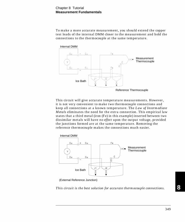
To make a more accurate measurement, you should extend the coppertest leads of the internal DMM closer to the measurement and hold theconnections to the thermocouple at the same temperature.
This circuit will give accurate temperature measurements. However,it is not very convenient to make two thermocouple connections andkeep all connections at a known temperature. The Law of IntermediateMetals eliminates the need for the extra connection. This empirical lawstates that a third metal (iron (Fe) in this example) inserted between twodissimilar metals will have no effect upon the output voltage, providedthe junctions formed are at the same temperature. Removing thereference thermocouple makes the connections much easier.
This circuit is the best solution for accurate thermocouple connections.
Ice Bath
Reference Thermocouple
MeasurementThermocouple
Internal DMM
MeasurementThermocouple
Ice Bath
Internal DMM
(External Reference Junction)
8
Chapter 8 TutorialMeasurement Fundamentals
349

In some measurement situations, however, it would be nice to removethe need for an ice bath (or any other fixed external reference). To dothis, an isothermal block is used to make the connections. An isothermalblock is an electrical insulator, but a good heat conductor. The additionalthermocouples created at J1 and J2 are now held at the same temperatureby the isothermal block.
Once the temperature of the isothermal block is known, accuratetemperature measurements can be made. A temperature sensor ismounted to the isothermal block to measure its temperature.
Thermocouples are available in a variety of types. The type is specifiedby a single letter. The table on the following page shows the mostcommonly used thermocouple types and some key characteristics of each.
Note: The thermocouple conversion routines used by the 34970A arecompatible with the International Temperature Scale of 1990 (ITS-90).
MeasurementThermocouple
ReferenceSensor
Isothermal Block(Internal or External Reference)
ReferenceTemperature
Internal DMM
Chapter 8 TutorialMeasurement Fundamentals
350

Loading Errors Due to Input Resistance Measurement loadingerrors occur when the resistance of the device-under-test (DUT) is anappreciable percentage of the instrument’s own input resistance.The diagram below shows this error source.
Where: Vs = Ideal DUT voltage Rs = DUT source resistance Ri = Input resistance (10 MΩ or >10 GΩ)
Error (%) = −100 x Rs
Rs + Ri
To minimize loading errors, set the DMM’s dc input resistance to greater than 10 GΩ when needed (for more information on dc inputresistance, see page 113).
VS
RS
HI
LO
Ri DMM
8
Chapter 8 TutorialMeasurement Fundamentals
357

Loading Errors Due to Input Bias Current The semiconductordevices used in the input circuits of the internal DMM have slightleakage currents called bias currents. The effect of the input biascurrent is a loading error at the internal DMM’s input terminals.The leakage current will approximately double for every 10 °Ctemperature rise, thus making the problem much more apparent athigher temperatures.
Where: Ib = DMM bias current Rs = DUT source resistance Ri = Input resistance (10 MΩ or >10 GΩ) Ci = DMM input capacitance
Error (V) = Ib x Rs
VS
RSHI
LO
Ib Ri DMM Ci
Chapter 8 TutorialMeasurement Fundamentals
358

Resistance MeasurementsAn ohmmeter measures the dc resistance of a device or circuit connectedto its input. Resistance measurements are performed by supplying aknown dc current to an unknown resistance and measuring thedc voltage drop.
The internal DMM offers two methods for measuring resistance:2-wire and 4-wire ohms. For both methods, the test current flows fromthe input HI terminal through the resistor being measured. For 2-wireohms, the voltage drop across the resistor being measured is sensedinternal to the DMM. Therefore, test lead resistance is also measured.For 4-wire ohms, separate “sense” connections are required. Since nocurrent flows in the sense leads, the resistance in these leads does notgive a measurement error.
4-Wire Ohms Measurements The 4-wire ohms method provides themost accurate way to measure small resistances. Test lead, multiplexer,and contact resistances are automatically reduced using this method.The 4-wire ohms method is often used in automated test applicationswhere long cable lengths, input connections, and a multiplexer existbetween the internal DMM and the device-under-test.
The recommended connections for 4-wire ohms measurements areshown in the diagram on the following page. A constant current source,forcing current I through unknown resistance R, develops a voltagemeasured by a dc voltage front end. The unknown resistance is thencalculated using Ohm’s Law.
Runknown
HI
LO
Itest
To Amplifier andAnalog-to-DigitalConverter
I
8
Chapter 8 TutorialMeasurement Fundamentals
369

The 4-wire ohms method is used in systems where lead resistances canbecome quite large and variable and in automated test applicationswhere cable lengths can be quite long. The 4-wire ohms method has theobvious disadvantage of requiring twice as many switches and twice asmany wires as the 2-wire method. The 4-wire ohms method is usedalmost exclusively for measuring lower resistance values in anyapplication, especially for values less than 10Ω and for high-accuracyrequirements such as RTD temperature transducers.
I test
Vmeter
HI-Source
LO-Source
LO-Sense
HI-Sense
R = Vmeter
Itest
Chapter 8 TutorialMeasurement Fundamentals
370

Low-Level Signal Multiplexing and SwitchingLow-level multiplexers are available in the following types: one-wire,2-wire, and 4-wire. The following sections in this chapter describe eachtype of multiplexer. The following low-level multiplexer modules areavailable with the 34970A.
• 34901A 20-Channel Armature Multiplexer• 34902A 16-Channel Reed Multiplexer• 34908A 40-Channel Single-Ended Multiplexer
An important feature of a multiplexer used as a DMM input channel isthat only one channel is connected at a time. For example, using amultiplexer module and the internal DMM, you could configure avoltage measurement on channel 1 and a temperature measurementon channel 2. The instrument first closes the channel 1 relay, makes thevoltage measurement, and then opens the relay before moving on tochannel 2 (called break-before-make switching).
Other low-level switching modules available with the 34970A includethe following:
• 34903A 20-Channel Actuator• 34904A 4x8 Two-Wire Matrix
Chapter 8 TutorialLow-Level Signal Multiplexing and Switching
378

One-Wire (Single-Ended) Multiplexers On the 34908A multiplexer, all of the 40 channels switch the HI inputonly, with a common LO for the module. The module also provides athermocouple reference junction for making thermocouple measurements(for more information on the purpose of an isothermal block, see page 350).
Two-Wire Multiplexers
The 34901A and 34902A multiplexers switch both HI and LO inputs,thus providing fully isolated inputs to the internal DMM or an externalinstrument. These modules also provide a thermocouple referencejunction for making thermocouple measurements (for more informationon the purpose of an isothermal block, see page 350).
Channel 1
Channel 2
Channel 3
Channel 4
To DMM
Note: Only one channel can be closed at a time; closing one channel will open thepreviously closed channel.
Channel 1
Channel 2
Channel 3
Channel 4
To DMM
Note: If any channels are configured to be part of the scan list, you cannot close multiple channels; closing one channel will open the previously closed channel.
Mo
du
le Referen
ce
8
Chapter 8 TutorialLow-Level Signal Multiplexing and Switching
379

Four-Wire Multiplexers You can make 4-wire ohms measurements using the 34901A and34902A multiplexers. For a 4-wire ohms measurement, the channels aredivided into two independent banks by opening the bank relay.
For 4-wire measurements, the instrument automatically pairs channel nwith channel n+10 (34901A) or n+8 (34902A) to provide the source andsense connections. For example, make the source connections to the HIand LO terminals on channel 2 and the sense connections to the HI andLO terminals on channel 12.
When making a 4-wire measurement, the test current flows through thesource connections from the HI terminal through the resistor beingmeasured. To eliminate the test lead resistance, a separate set of senseconnections are used as shown below.
Channel 1 Source
Channel 2 Source
Channel 11 Sense
Channel 12 Sense
To DMM Source
To DMM Sense
Bank Relay
Note: If any channels are configured to be part of the scan list, you cannot close multiple channels; closing one channel will open the previously closed channel.
Source Sense
HI
LO
R
+
_
Chapter 8 TutorialLow-Level Signal Multiplexing and Switching
380

Signal Routing and Multiplexing When used stand-alone for signal routing (not scanning or connected tothe internal DMM), multiple channels on the 34901A and 34902Amultiplexers can be closed at the same time. You must be careful thatthis does not create a hazardous condition (for example, connecting twopower sources together).
Note that a multiplexer is not directional. For example, you can use amultiplexer with a source (such as a DAC) to connect a single source tomultiple test points as shown below.
MultiplexerDAC
Channel 3
Channel 2
OUT
GND
COM H
COM L
Channel 4
Channel 1
Mo
du
le Referen
ce
8
Chapter 8 TutorialLow-Level Signal Multiplexing and Switching
381

DC, Resistance, and Temperature Accuracy Specifications
± ( % of reading + % of range ) [1]
Includes measurement error, switching error, and transducer conversion error
Function Range [3] Test Current orBurden Voltage
24 Hour [2]
23 °C ± 1 °C
90 Day
23 °C ± 5 °C
1 Year
23 °C ± 5 °C
Temperature Coefficient /°C 0 °C – 18 °C 28 °C – 55 °C
DC Voltage 100.0000 mV1.000000 V 10.00000 V 100.0000 V 300.000 V
0.0030 + 0.00350.0020 + 0.00060.0015 + 0.00040.0020 + 0.00060.0020 + 0.0020
0.0040 + 0.00400.0030 + 0.00070.0020 + 0.00050.0035 + 0.00060.0035 + 0.0030
0.0050 + 0.00400.0040 + 0.00070.0035 + 0.00050.0045 + 0.00060.0045 + 0.0030
0.0005 + 0.00050.0005 + 0.00010.0005 + 0.00010.0005 + 0.00010.0005 + 0.0003
Resistance [4] 100.0000 Ω1.000000 kΩ10.00000 kΩ100.0000 kΩ1.000000 MΩ10.00000 MΩ100.0000 MΩ
1 mA current source1 mA100 µA10 µA5 µA500 nA500 nA || 10 MΩ
0.0030 + 0.00350.0020 + 0.00060.0020 + 0.00050.0020 + 0.00050.002 + 0.0010.015 + 0.0010.300 + 0.010
0.008 + 0.0040.008 + 0.0010.008 + 0.0010.008 + 0.0010.008 + 0.0010.020 + 0.0010.800 + 0.010
0.010 + 0.0040.010 + 0.0010.010 + 0.0010.010 + 0.0010.010 + 0.0010.040 + 0.0010.800 + 0.010
0.0006 + 0.00050.0006 + 0.00010.0006 + 0.00010.0006 + 0.00010.0010 + 0.00020.0030 + 0.00040.1500 + 0.0002
DC Current34901A Only
10.00000 mA100.0000 mA1.000000 A
< 0.1 V burden< 0.6 V< 2 V
0.005 + 0.010 0.010 + 0.004 0.050 + 0.006
0.030 + 0.0200.030 + 0.0050.080 + 0.010
0.050 + 0.0200.050 + 0.0050.100 + 0.010
0.002 + 0.0020 0.002 + 0.0005 0.005 + 0.0010
Temperature Type Best Range Accuracy [5] Extended Range Accuracy [5]
Thermocouple [6] BEJKNRST
1100°C to 1820°C-150°C to 1000°C-150°C to 1200°C-100°C to 1200°C -100°C to 1300°C 300°C to 1760°C 400°C to 1760°C-100°C to 400°C
1.2°C1.0°C1.0°C1.0°C1.0°C1.2°C1.2°C1.0°C
400°C to 1100°C-200°C to -150°C-210°C to -150°C-200°C to -100°C-200°C to -100°C -50°C to 300°C -50°C to 400°C
-200°C to -100°C
1.8°C1.5°C1.2°C1.5°C1.5°C1.8°C1.8°C1.5°C
0.03°C0.03°C0.03°C0.03°C0.03°C0.03°C0.03°C0.03°C
RTD R0 from 49Ωto 2.1 kΩ
-200°C to 600°C 0.06°C 0.003°C
Thermistor 2.2 k, 5 k, 10 k -80°C to 150°C 0.08°C 0.002°C
[1] Specifications are for 1 hour warm up and 61⁄2 digits[2] Relative to calibration standards[3] 20% over range on all ranges except 300 Vdc and 1 Adc ranges[4] Specifications are for 4-wire ohms function or 2-wire ohms using Scaling to remove the offset. Without Scaling, add 4Ω additional error in 2-wire ohms function.[5] 1 year accuracy. For total measurement accuracy, add temperature probe error. [6] Thermocouple specifications not guaranteed when 34907A module is present
Chapter 9 SpecificationsDC, Resistance, and Temperature Accuracy Specifications
404

To Calculate Total Measurement ErrorEach specification includes correction factors which account for errorspresent due to operational limitations of the internal DMM. This sectionexplains these errors and shows how to apply them to your measurements.Refer to “Interpreting Internal DMM Specifications,” starting on page 416,to get a better understanding of the terminology used and to help youinterpret the internal DMM’s specifications.
The internal DMM’s accuracy specifications are expressed in the form: (% of reading + % of range). In addition to the reading error and rangeerror, you may need to add additional errors for certain operatingconditions. Check the list below to make sure you include all measurementerrors for a given function. Also, make sure you apply the conditions asdescribed in the footnotes on the specification pages.
• If you are operating the internal DMM outside the 23 °C ± 5 °Ctemperature range specified, apply an additional temperaturecoefficient error.
• For dc voltage, dc current, and resistance measurements, you mayneed to apply an additional reading speed error.
• For ac voltage and ac current measurements, you may need to applyan additional low frequency error or crest factor error.
Understanding the “ % of reading ” Error The reading errorcompensates for inaccuracies that result from the function and rangeyou select, as well as the input signal level. The reading error variesaccording to the input level on the selected range. This error isexpressed in percent of reading. The following table shows the readingerror applied to the internal DMM’s 24-hour dc voltage specification.
Range Input LevelReading Error(% of reading)
ReadingError Voltage
10 Vdc10 Vdc10 Vdc
10 Vdc1 Vdc
0.1 Vdc
0.00150.00150.0015
≤ 150 µV≤ 15 µV≤ 1.5 µV
Chapter 9 SpecificationsTo Calculate Total Measurement Error
414

Understanding the “ % of range ” Error The range error compensatesfor inaccuracies that result from the function and range you select.The range error contributes a constant error, expressed as a percent ofrange, independent of the input signal level. The following table showsthe range error applied to the DMM’s 24-hour dc voltage specification.
Range Input LevelRange Error(% of range)
RangeError Voltage
10 Vdc10 Vdc10 Vdc
10 Vdc1 Vdc
0.1 Vdc
0.00040.00040.0004
≤ 40 µV≤ 40 µV≤ 40 µV
Total Measurement Error To compute the total measurement error,add the reading error and range error. You can then convert the totalmeasurement error to a “percent of input” error or a “ppm (part-per-million) of input” error as shown below.
% of input error = Total Measurement Error Input Signal Level
× 100
ppm of input error = Total Measurement Error Input Signal Level
× 1,000,000
Example: Computing Total Measurement Error
Assume that a 5 Vdc signal is input to the DMM on the 10 Vdc range.Compute the total measurement error using the 90-day accuracyspecification of ±(0.0020% of reading + 0.0005% of range).
Reading Error = 0.0020% x 5 Vdc = 100 µV
Range Error = 0.0005% x 10 Vdc = 50 µV
Total Error = 100 µV + 50 µV = ± 150 µV= ± 0.0030% of 5 Vdc= ± 30 ppm of 5 Vdc
9
Chapter 9 SpecificationsTo Calculate Total Measurement Error
415

Interpreting Internal DMM SpecificationsThis section is provided to give you a better understanding of theterminology used and will help you interpret the internal DMM’sspecifications.
Number of Digits and Overrange The “number of digits” specification is the most fundamental, andsometimes, the most confusing characteristic of a multimeter.The number of digits is equal to the maximum number of “9’s” themultimeter can measure or display. This indicates the number offull digits. Most multimeters have the ability to overrange and adda partial or “1⁄2” digit.
For example, the internal DMM can measure 9.99999 Vdc on the 10 Vrange. This represents six full digits of resolution. The internal DMMcan also overrange on the 10 V range and measure up to a maximum of12.00000 Vdc. This corresponds to a 61⁄2-digit measurement with 20%overrange capability.
Sensitivity
Sensitivity is the minimum level that the internal DMM can detect for agiven measurement. Sensitivity defines the ability of the internal DMMto respond to small changes in the input level. For example, suppose youare monitoring a 1 mVdc signal and you want to adjust the level towithin ±1 µV. To be able to respond to an adjustment this small, thismeasurement would require a multimeter with a sensitivity of at least1 µV. You could use a 61⁄2-digit multimeter if it has a 1 Vdc or smallerrange. You could also use a 41⁄2-digit multimeter with a 10 mVdc range.
For ac voltage and ac current measurements, note that the smallestvalue that can be measured is different from the sensitivity. For theinternal DMM, these functions are specified to measure down to 1% ofthe selected range. For example, the internal DMM can measure downto 1 mV on the 100 mV range.
Chapter 9 SpecificationsInterpreting Internal DMM Specifications
416

Resolution Resolution is the numeric ratio of the maximum displayed value dividedby the minimum displayed value on a selected range. Resolution isoften expressed in percent, parts-per-million (ppm), counts, or bits.For example, a 61⁄2-digit multimeter with 20% overrange capability candisplay a measurement with up to 1,200,000 counts of resolution.This corresponds to about 0.0001% (1 ppm) of full scale, or 21 bitsincluding the sign bit. All four specifications are equivalent.
Accuracy
Accuracy is a measure of the “exactness” to which the internal DMM’smeasurement uncertainty can be determined relative to the calibrationreference used. Absolute accuracy includes the internal DMM’s relativeaccuracy specification plus the known error of the calibration referencerelative to national standards (such as the U.S. National Institute ofStandards and Technology). To be meaningful, the accuracy specificationsmust be accompanied with the conditions under which they are valid.These conditions should include temperature, humidity, and time.
There is no standard convention among instrument manufacturers forthe confidence limits at which specifications are set. The table belowshows the probability of non-conformance for each specification with thegiven assumptions.
SpecificationCriteria
Mean ± 2 sigmaMean ± 3 sigma
Probabilityof Failure
4.5%0.3%
Variations in performance from reading to reading, and instrumentto instrument, decrease for increasing number of sigma for a givenspecification. This means that you can achieve greater actualmeasurement precision for a specific accuracy specification number.The 34970A is designed and tested to meet performance better thanmean ±3 sigma of the published accuracy specifications.
9
Chapter 9 SpecificationsInterpreting Internal DMM Specifications
417
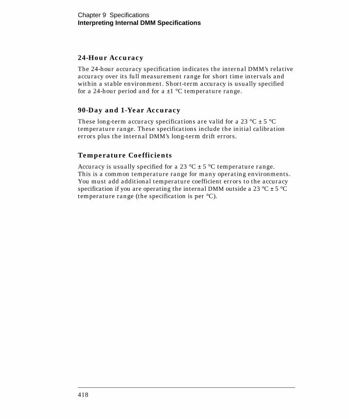
24-Hour Accuracy The 24-hour accuracy specification indicates the internal DMM’s relativeaccuracy over its full measurement range for short time intervals andwithin a stable environment. Short-term accuracy is usually specifiedfor a 24-hour period and for a ±1 °C temperature range.
90-Day and 1-Year Accuracy
These long-term accuracy specifications are valid for a 23 °C ± 5 °Ctemperature range. These specifications include the initial calibrationerrors plus the internal DMM’s long-term drift errors.
Temperature Coefficients
Accuracy is usually specified for a 23 °C ± 5 °C temperature range.This is a common temperature range for many operating environments.You must add additional temperature coefficient errors to the accuracyspecification if you are operating the internal DMM outside a 23 °C ± 5 °Ctemperature range (the specification is per °C).
Chapter 9 SpecificationsInterpreting Internal DMM Specifications
418