Embed Size (px)
Citation preview
A DIVISION OF DOUGLAS DYNAMICS, L.L.C.
May 1, 2008Lit. No. 29206, Rev. 05
CAUTIONRead this document before installing the snowplow.
CAUTIONSee your sales outlet/Web site for specifi c vehicle application recommendations before installation. The Kit Selection Guide/Selection List has specifi c vehicle and snowplow requirements.
29048, 29049, 29050, 29051, 29052, 20953, 29054, 29400-2
HARNESS KIT3-PORT ISOLATION MODULE
LIGHT SYSTEM
w/3-PLUG SYSTEM HARNESSES
Installation Instructions
Lit. No.29206, Rev. 05 2 May 1, 2008
29048, 29049, 29050, 29051, 29052, 29053, 29054, 29400-2
NOTE: Indicates a situation or action that can lead to damage to your snowplow and vehicle or other property. Other useful information can also be described.
FUSES
The snowplow electrical and hydraulic systems contain several blade-style automotive fuses. If a problem should occur and fuse replacement is necessary, the replacement fuse must be of the same type and amperage rating as the original. Installing a fuse with a higher rating can damage the system and could start a fi re. Fuse Replacement, including fuse ratings and locations, is located in the Maintenance Section of the Owner's Manual.
BATTERY SAFETY
SAFETY DEFINITIONS
CAUTIONIndicates a potentially hazardous situation that, if not avoided, may result in minor or moderate injury. It may also be used to alert against unsafe practices.
TORQUE CHART
Recommended Fastener Torque Chart (ft-lb)
Size SAEGrade 2
SAEGrade 5
SAEGrade 8
1/4-205/16-183/8-163/8-247/16-141/2-139/16-125/8-113/4-107/8-91-8
611192430456693150150220
91831465075110150250378583
1328466875115165225370591893
Metric Grade 8.8 (ft-lb)Size TorqueSizeTorque
M 6M 8M 10
M 12M 14M 16
71735
6095155
These torque values apply to fastenersexcept those noted in the instruction.
CAUTIONRead instructions before assembling. Fasteners should be fi nger tight until instructed to tighten according to the torque chart. Use standard methods and practices when attaching snowplow, including proper personal protective safety equipment.
WARNINGIndicates a potentially hazardous situation that, if not avoided, could result in death or serious personal injury.
CAUTIONBatteries normally produce explosive gases which can cause personal injury. Therefore, do not allow fl ames, sparks or lit tobacco to come near the battery. When charging or working near a battery, always cover your face and protect your eyes, and also provide ventilation. Batteries contain sulfuric acid which burns skin, eyes and clothing. Disconnect the battery before removing or replacing any electrical components.
Lit. No. 29206, Rev. 05 3 May 1, 2008
29048, 29049, 29050, 29051, 29052, 29053, 29054, 29400-2
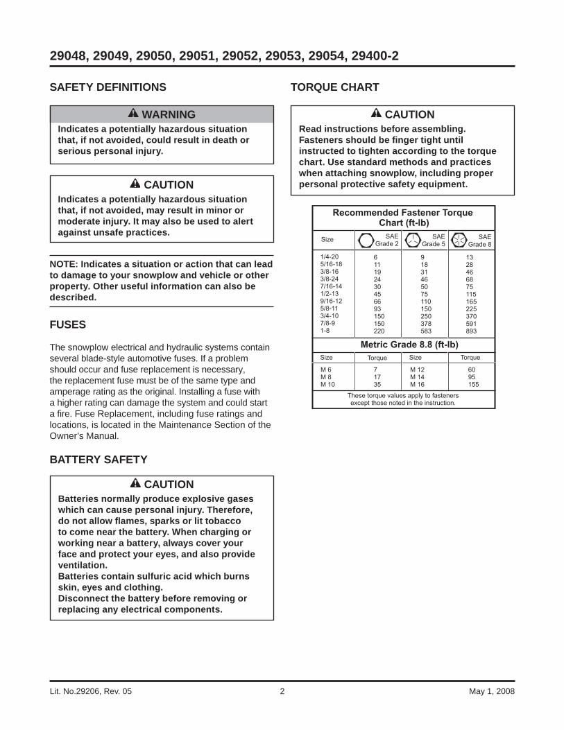
TYPICAL 3-PLUG, 3-PORT MODULE SYSTEM DIAGRAM
Ada
pter
15-A
mp
Fuse
(Par
k/Tu
rn)
Bat
tery
10.0
-Am
p Fu
ses
(Sno
wpl
ow P
ark/
Turn
&S
now
plow
Con
trol)
Turn
Sig
nal
Con
figur
atio
n Pl
ug
(not
use
d)
Typi
cal P
lug-
In H
arne
ss
Vehi
cle
Ligh
ting
Har
ness
(11-
Pin
)
Vehi
cle
Con
trol
Har
ness
(3-P
in)
Vehi
cle
Hea
dlam
ps
Vehi
cle
Hea
dlam
ps
Park
/Tur
nLa
mps
Park
/Tur
nLa
mps
Fact
ory
Veh
icle
Har
ness
Fact
ory
Veh
icle
Har
ness
Vehi
cle
Bat
tery
Cab
le
Mot
orR
elayBat
tery
Cab
le
To S
now
plow
Con
trol
To S
witc
hed
Acc
esso
ry
Fire
Wal
l3-
Port
Mod
ule
7.5-
Am
p Fu
se(S
traig
ht B
lade
Con
trol)
RE
D
BLK
RED/GRN
RED/BRN
RE
D
BLK/ORN
BLK
/OR
N
RED
BLK/ORN
Lit. No.29206, Rev. 05 4 May 1, 2008
29048, 29049, 29050, 29051, 29052, 29053, 29054, 29400-2
CAUTIONBefore installing self-drilling screws or drilling mounting holes, check the selected mounting area for any wires, hoses, or other obstructions.
MOTOR RELAY AND VEHICLE BATTERY CABLE INSTALLATION
NOTE: When instructed, make all snowplow battery cable connections to the auxiliary battery, if vehicle is so equipped.
NOTE: For vehicles equipped with a tilt cab or tilt hood, a service loop will be necessary when making harness or cable transitions from the cab/hood to the frame. Check the cable installation for interference by raising and lowering the cab/hood a number of times. Add anti-chafi ng material (installer-supplied) as needed.
1. Turn off the vehicle ignition.
2. Disconnect both the NEGATIVE (–) and the POSITIVE (+) battery cables.
3 Choose a location on the vehicle where the motor relay will be protected from road splash and debris. Motor relay must be within 18" of the vehicle battery. (The motor relay can be farther from the battery if the battery cable provided with either the plug-in harness or adapter kit is longer than 22".)
NOTE: Position motor relay terminals up, horizontal or in between.
CAUTIONBatteries normally produce explosive gases which can cause personal injury. Therefore, do not allow fl ames, sparks or lit tobacco to come near the battery. When charging or working near a battery, always cover your face and protect your eyes, and also provide ventilation.Batteries contain sulfuric acid which burns skin, eyes and clothing. Disconnect the battery before removing or replacing any electrical components.
4. Drill two 9/32" mounting holes using the motor relay mounting plate as a template. Mount the motor relay using 1/4" x 3/4" cap screws, washers and locknuts.
5. Route the supplied vehicle battery cable from the grille or bumper to the location chosen for mounting the motor relay, avoiding any sharp edges and hot or moving parts. Cable tie only the end section closest to the grille. Lengthening the vehicle battery cable may be necessary on vehicles with batteries located under or behind the cab. If lengthening cables is necessary, use the same gauge wire as the vehicle battery cable, and cover all connections with dual-wall heatshrink tubing to prevent shorting.
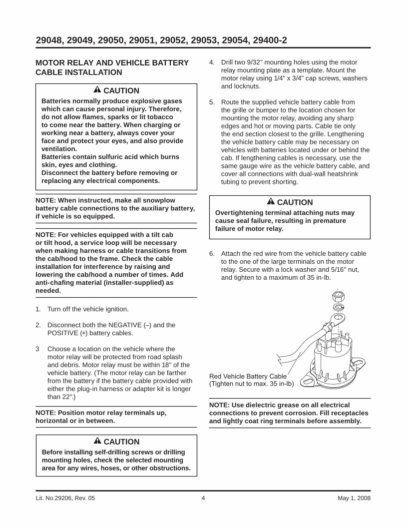
6. Attach the red wire from the vehicle battery cable to the one of the large terminals on the motor relay. Secure with a lock washer and 5/16" nut, and tighten to a maximum of 35 in-lb.
NOTE: Use dielectric grease on all electrical connections to prevent corrosion. Fill receptacles and lightly coat ring terminals before assembly.
CAUTIONOvertightening terminal attaching nuts may cause seal failure, resulting in premature failure of motor relay.
Red Vehicle Battery Cable(Tighten nut to max. 35 in-lb)
Lit. No. 29206, Rev. 05 5 May 1, 2008
29048, 29049, 29050, 29051, 29052, 29053, 29054, 29400-2
PLUG COVER INSTALLATION
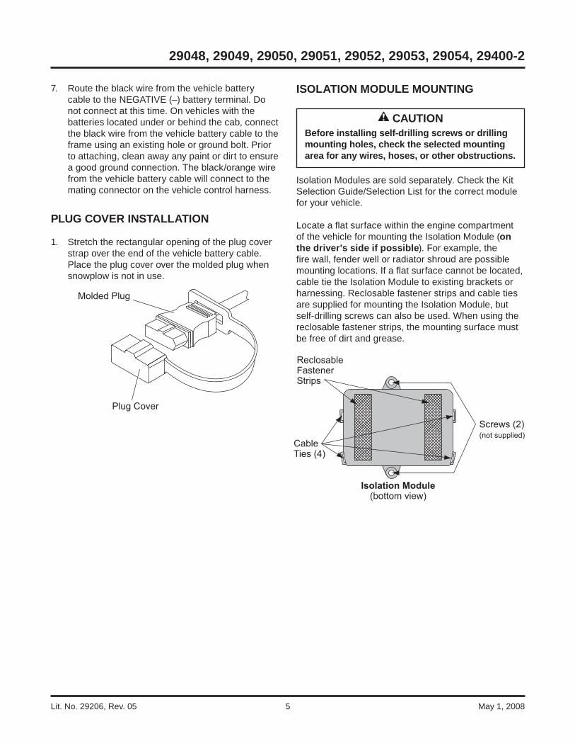
1. Stretch the rectangular opening of the plug cover strap over the end of the vehicle battery cable. Place the plug cover over the molded plug when snowplow is not in use.
Plug Cover
Molded Plug
ISOLATION MODULE MOUNTING
Isolation Modules are sold separately. Check the Kit Selection Guide/Selection List for the correct module for your vehicle.
Locate a fl at surface within the engine compartment of the vehicle for mounting the Isolation Module (on the driver's side if possible). For example, the fi re wall, fender well or radiator shroud are possible mounting locations. If a fl at surface cannot be located, cable tie the Isolation Module to existing brackets or harnessing. Reclosable fastener strips and cable ties are supplied for mounting the Isolation Module, but self-drilling screws can also be used. When using the reclosable fastener strips, the mounting surface must be free of dirt and grease.
CableTies (4)
ReclosableFastenerStrips
Isolation Module(bottom view)
Screws (2)(not supplied)
CAUTIONBefore installing self-drilling screws or drilling mounting holes, check the selected mounting area for any wires, hoses, or other obstructions.
7. Route the black wire from the vehicle battery cable to the NEGATIVE (–) battery terminal. Do not connect at this time. On vehicles with the batteries located under or behind the cab, connect the black wire from the vehicle battery cable to the frame using an existing hole or ground bolt. Prior to attaching, clean away any paint or dirt to ensure a good ground connection. The black/orange wire from the vehicle battery cable will connect to the mating connector on the vehicle control harness.
Lit. No.29206, Rev. 05 6 May 1, 2008
29048, 29049, 29050, 29051, 29052, 29053, 29054, 29400-2
INSTALLATION OF 3-PORT ISOLATION MODULE PN 29760-1
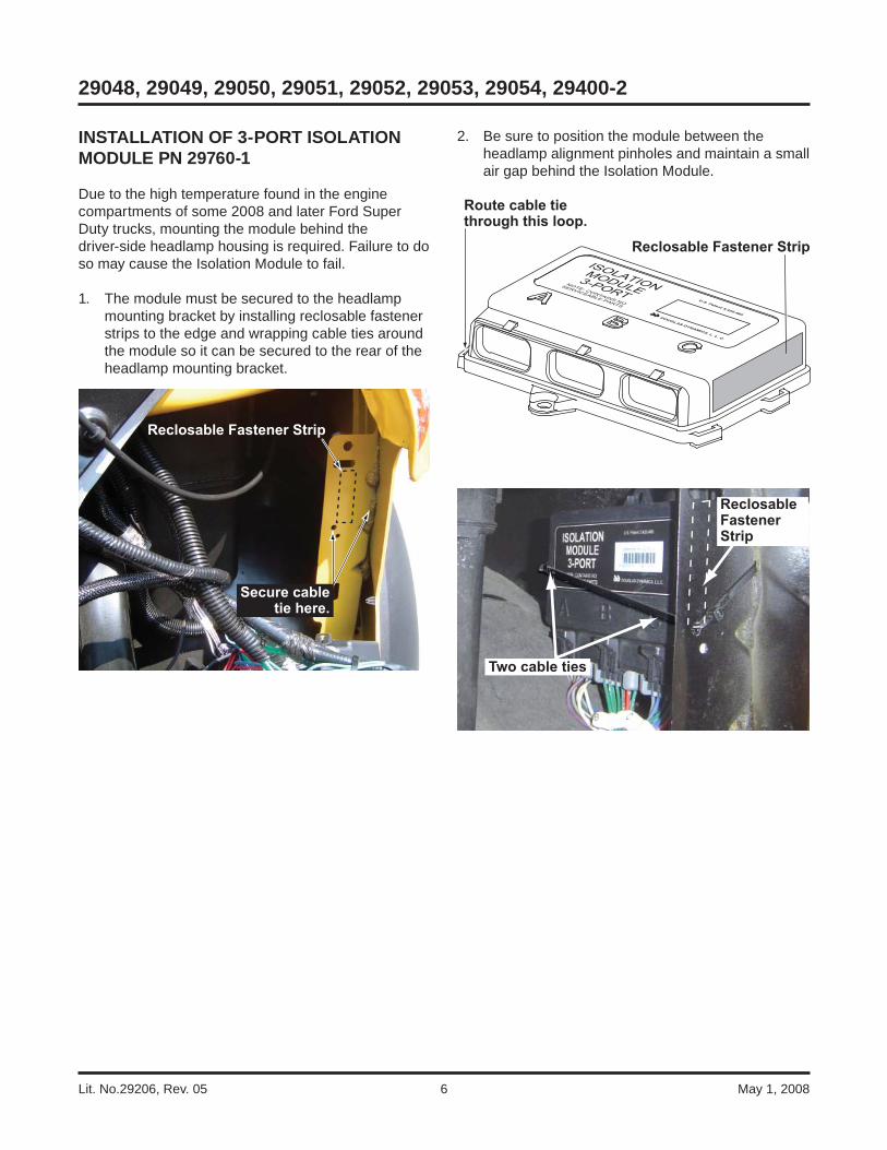
Due to the high temperature found in the engine compartments of some 2008 and later Ford Super Duty trucks, mounting the module behind the driver-side headlamp housing is required. Failure to do so may cause the Isolation Module to fail.
1. The module must be secured to the headlamp mounting bracket by installing reclosable fastener strips to the edge and wrapping cable ties around the module so it can be secured to the rear of the headlamp mounting bracket.
Reclosable Fastener Strip
Secure cable tie here.
2. Be sure to position the module between the headlamp alignment pinholes and maintain a small air gap behind the Isolation Module.
Reclosable Fastener Strip
Route cable tiethrough this loop.
Two cable ties
ReclosableFastenerStrip

Lit. No. 29206, Rev. 05 7 May 1, 2008
29048, 29049, 29050, 29051, 29052, 29053, 29054, 29400-2
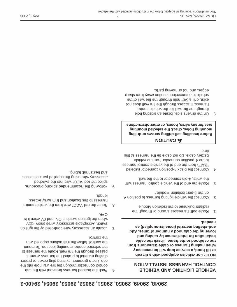
VEHICLE LIGHTING AND VEHICLE CONTROL HARNESS INSTALLATION
Vehicle lighting and vehicle control harnesses are designed to plug into one another when the snowplow is not attached. Plug the harnesses together before cable tying them to ensure adequate length.
NOTE: For vehicles equipped with a tilt cab or tilt hood, a service loop will be necessary when making harness or cable transitions from the cab/hood to the frame. Check the cable installation for interference by raising and lowering the cab/hood a number of times. Add anti-chafi ng material (installer-supplied) as needed.
1. Route both harnesses around or through the radiator bulkhead to the Isolation Module.
2. Make the following connections:
10-position connector from vehicle control • harness to 10-position connector from adapter included with harness kit.
Single-wire connector from vehicle control • harness to single-wire connector from adapter included with harness kit.
4-position connector from adapter included with • harness kit to 4-position connector from plug-in harness.
Vehicle lighting harness to position A on the 3-port • Isolation Module.*
NOTE: The 3-position connector on the vehicle control harness (4-port module confi guration plug) will not be used. Cover the terminals with dielectric grease and cap off with electrical tape.
*For installations requiring an adapter, follow the instructions included with the adapter.
3. Route the end of the vehicle control harness with the white, 6-pin connector or the 10 loose terminals to the fi re wall. Route the vehicle control harness breakout with four wires to the motor relay.
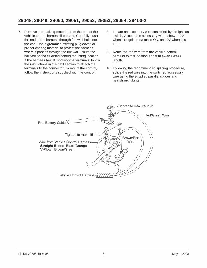
Motor relay small terminal connections: Straight blades: brown/red and black/orange V-plows: brown/red and brown/green
Secure wires to small terminals of motor relay with #10 lock washers and 10-32 nuts, and tighten to a maximum 15 in-lb.
4. Connect the single-wire connector (black/orange wire) from the vehicle control harness breakout to the single-wire connector (black/orange wire) from the vehicle battery cable. Do not cable tie the harness at this time.
5. Attach the supplied red battery cable and the red-green wire from the vehicle control harness to a large terminal on the motor relay with a lock washer and 5/16" nut, and tighten to a maximum 35 in-lb. Route the supplied red battery cable between motor relay terminal and POSITIVE (+) battery terminal, avoiding sharp edges and hot or moving parts. Do not make battery connection at this time.
6. On the driver's side, locate an existing hole through the fi re wall for the vehicle control harness. If access through the fi re wall does not exist, drill a 5/8" hole through the fi re wall of the vehicle in a convenient location away from sharp edges, and hot or moving parts.
CAUTIONOvertightening terminal attaching nuts may cause seal failure, resulting in premature failure of motor relay.
CAUTIONBefore installing self-drilling screws or drilling mounting holes, check the selected mounting area for any wires, hoses, or other obstructions.
Lit. No.29206, Rev. 05 8 May 1, 2008
29048, 29049, 29050, 29051, 29052, 29053, 29054, 29400-2
7. Remove the packing material from the end of the vehicle control harness if present. Carefully push the end of the harness through fi re wall hole into the cab. Use a grommet, existing plug cover, or proper chafi ng material to protect the harness where it passes through the fi re wall. Route the harness to the selected control mounting location. If the harness has 10 socket-type terminals, follow the instructions in the next section to attach the terminals to the connector. To mount the control, follow the instructions supplied with the control.
8. Locate an accessory wire controlled by the ignition switch. Acceptable accessory wires show +12V when the ignition switch is ON, and 0V when it is OFF.
9. Route the red wire from the vehicle control harness to this location and trim away excess length.
10. Following the recommended splicing procedure, splice the red wire into the switched accessory wire using the supplied parallel splices and heatshrink tubing.
Red Battery Cable
Tighten to max. 35 in-lb.
Brown/RedWire
Vehicle Control Harness
Wire from Vehicle Control Harness Straight Blade: Black/Orange V-Plow: Brown/Green
Tighten to max. 15 in-lb.
Red/Green Wire
Lit. No. 29206, Rev. 05 9 May 1, 2008
29048, 29049, 29050, 29051, 29052, 29053, 29054, 29400-2
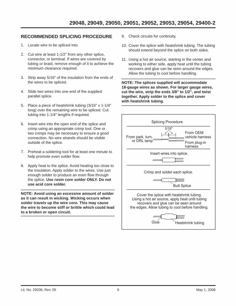
9. Check circuits for continuity.
10. Cover the splice with heatshrink tubing. The tubing should extend beyond the splice on both sides.
11. Using a hot air source, starting in the center and working to either side, apply heat until the tubing recovers and glue can be seen around the edges. Allow the tubing to cool before handling.
NOTE: The splices supplied will accommodate 18-gauge wires as shown. For larger gauge wires, cut the wire, strip the ends 3/8" to 1/2", and twist together. Apply solder to the splice and cover with heatshrink tubing.
Heatshrink tubingGlue
Cover the splice with heatshrink tubing. Using a hot air source, apply heat until tubing
recovers and glue can be seen around the edges. Allow tubing to cool before handling.
Butt Splice
Crimp and solder each splice.
Insert wires into splice.
From OEMvehicle harnessFrom plug-inharness
5/16"
Splicing Procedure
From park, turn, or DRL lamp
RECOMMENDED SPLICING PROCEDURE
1. Locate wire to be spliced into.
2. Cut wire at least 1-1/2" from any other splice, connector, or terminal. If wires are covered by tubing or braid, remove enough of it to achieve the minimum clearance required.
3. Strip away 5/16" of the insulation from the ends of the wires to be spliced.
4. Slide two wires into one end of the supplied parallel splice.
5. Place a piece of heatshrink tubing (3/16" x 1-1/4" long) over the remaining wire to be spliced. Cut tubing into 1-1/4" lengths if required.
6. Insert wire into the open end of the splice and crimp using an appropriate crimp tool. One or two crimps may be necessary to ensure a good connection. No wire strands should be visible outside of the splice.
7. Preheat a soldering tool for at least one minute to help promote even solder fl ow.
8. Apply heat to the splice. Avoid heating too close to the insulation. Apply solder to the wires. Use just enough solder to produce an even fl ow through the splice. Use rosin core solder ONLY. Do not use acid core solder.
NOTE: Avoid using an excessive amount of solder as it can result in wicking. Wicking occurs when solder travels up the wire core. This may cause the wire to become stiff or brittle which could lead to a broken or open circuit.

Lit. No.29206, Rev. 05 10 May 1, 2008
29048, 29049, 29050, 29051, 29052, 29053, 29054, 29400-2
PLUG-IN HARNESS INSTALLATION: COLORADO / CANYON
DRL Installations (module PN 29070)
1. Remove the headlamp connectors. Connect the plug-in harness to the mating connectors removed from the headlamps. Connect the plug-in harness to the mating connections at the headlamps. Route the plug-in harness to the 3-port Isolation Module. Connect the plug-in harness to the module by matching harness connector B with module port B and harness connector C with module port C.
2. Splice the "PARK" wire from the plug-in harness into the parking light wire at the vehicle headlamp following the splicing procedure.
3. Connect the dark blue and dark green turn signal wires from the plug-in harness to the vehicle front turn signal lamps.
4. Cable tie the vehicle control harness, vehicle lighting harness and plug-in harness away from any sharp, hot or moving parts. The vehicle control harness and vehicle lighting harness are designed to plug into one another for storage. Skip ahead to Turn Signal Confi guration Plug section.
PLUG-IN HARNESS INSTALLATION: VEHICLES USING THE 29053 HARNESS KIT
1. Locate the passenger-side OEM vehicle headlamp connector located near the tilt-hood hinge below the headlamp housing.
2. Remove the small, light gray connector lock by carefully sliding it back away from the connector. Separate the connectors by pushing down on the locking tab and pulling them apart.
3. Connect the plug-in harness female connector to the male OEM vehicle headlamp connector. Reinstall the small, light gray connector lock.
4. Connect the plug-in harness male connector to the female OEM vehicle headlamp connector.
5. Route the remaining half of the plug-in harness to the driver-side OEM vehicle headlamp connector, and repeat Steps 2–4.
6. Route the plug-in harness to the 3-port Isolation Module by running the harness along the existing cables underneath the engine and radiator area. Connect the plug-in harness to the module by matching harness connector B with module port B and harness connector C with module port C.
7. Cable tie the vehicle control harness, vehicle lighting harness and plug-in harness away from any sharp, hot or moving parts. The vehicle control harness and vehicle lighting harness are designed to plug into one another for storage.
8. Skip ahead to Turn Signal Confi guration Plug section.

Lit. No. 29206, Rev. 05 11 May 1, 2008
29048, 29049, 29050, 29051, 29052, 29053, 29054, 29400-2
PLUG-IN HARNESS INSTALLATION: VEHICLES USING THE 29054 HARNESS KIT
1. Locate the passenger-side OEM vehicle headlamp connector located near the tilt-hood hinge below the headlamp housing.
2. Remove the small, light gray connector lock by depressing the tabs on both sides and pulling outward. Save the connector lock.
3. Disconnect the connector by lifting up on the locking tab and pulling it apart. Carefully unclip the vehicle headlamp harness and reroute it back to the frame, cable tying as necessary.
4. Connect the plug-in harness female connector to the male OEM vehicle headlamp connector. Reinstall the small, light gray connector lock. Route the plug-in harness back toward the frame using existing cable clips.
5. Connect the plug-in harness male connector to the female OEM vehicle headlamp connector.
6. Route the plug-in harness to the 3-port Isolation Module. Connect the plug-in harness to the module by matching harness connector B with module port B and harness connector C with module port C.
7. Cable tie the vehicle control harness, vehicle lighting harness and plug-in harness away from any sharp, hot or moving parts. The vehicle control harness and vehicle lighting harness are designed to plug into one another for storage.
8. There is no turn signal confi guration plug on this harness. Skip ahead to Under-Dash Vehicle Control Harness Connector Pin Assignments section.
Lit. No.29206, Rev. 05 12 May 1, 2008
29048, 29049, 29050, 29051, 29052, 29053, 29054, 29400-2
PLUG-IN HARNESS INSTALLATION:ALL OTHER APPLICATIONS
NOTE: For vehicles equipped with a tilt cab or tilt hood, a service loop will be necessary when making harness or cable transitions from the cab/hood to the frame. Check the cable installation for interference by raising and lowering the cab/hood a number of times. Add anti-chafi ng (installer-supplied) as needed.
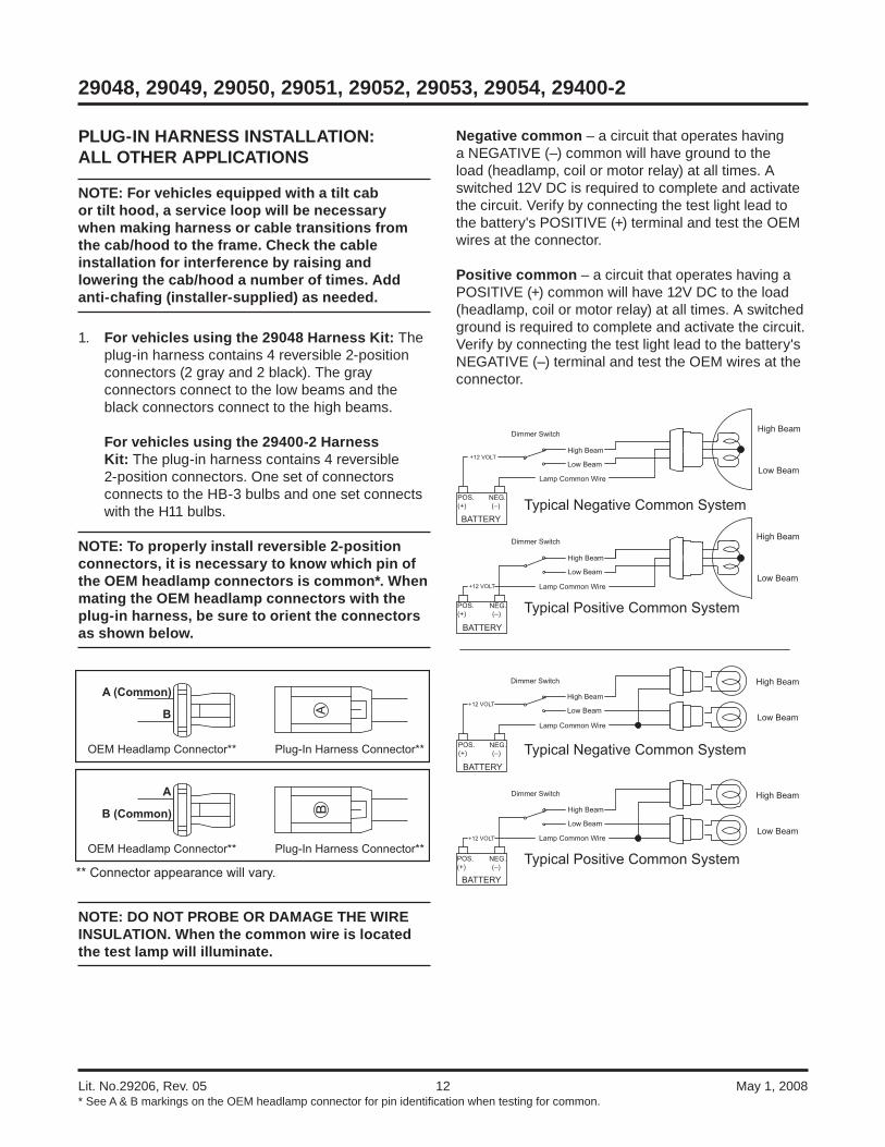
1. For vehicles using the 29048 Harness Kit: The plug-in harness contains 4 reversible 2-position connectors (2 gray and 2 black). The gray connectors connect to the low beams and the black connectors connect to the high beams.
For vehicles using the 29400-2 Harness Kit: The plug-in harness contains 4 reversible 2-position connectors. One set of connectors connects to the HB-3 bulbs and one set connects with the H11 bulbs.
NOTE: To properly install reversible 2-position connectors, it is necessary to know which pin of the OEM headlamp connectors is common*. When mating the OEM headlamp connectors with the plug-in harness, be sure to orient the connectors as shown below.
NOTE: DO NOT PROBE OR DAMAGE THE WIRE INSULATION. When the common wire is located the test lamp will illuminate.
A (Common)
B
** Connector appearance will vary.
OEM Headlamp Connector** Plug-In Harness Connector**
A
B (Common)
OEM Headlamp Connector** Plug-In Harness Connector**
* See A & B markings on the OEM headlamp connector for pin identifi cation when testing for common.
Negative common – a circuit that operates having a NEGATIVE (–) common will have ground to the load (headlamp, coil or motor relay) at all times. A switched 12V DC is required to complete and activate the circuit. Verify by connecting the test light lead to the battery's POSITIVE (+) terminal and test the OEM wires at the connector.
Positive common – a circuit that operates having a POSITIVE (+) common will have 12V DC to the load (headlamp, coil or motor relay) at all times. A switched ground is required to complete and activate the circuit. Verify by connecting the test light lead to the battery's NEGATIVE (–) terminal and test the OEM wires at the connector.
Typical Negative Common System
Typical Positive Common System
Typical Negative Common System
Typical Positive Common System
High Beam
Low Beam
High Beam
Low Beam
High Beam
Low Beam
High Beam
Low Beam
High Beam
Low Beam
High Beam
Low Beam
High Beam
Low Beam
High Beam
Low Beam
Dimmer Switch
Dimmer Switch
Dimmer Switch
Dimmer Switch
Lamp Common Wire
Lamp Common Wire
Lamp Common Wire
Lamp Common Wire
BATTERY
POS.(+)
NEG.(–)
+12 VOLT
BATTERY
POS.(+)
NEG.(–)
+12 VOLT
BATTERY
POS.(+)
NEG.(–)
+12 VOLT
BATTERY
POS.(+)
NEG.(–)
+12 VOLT

Lit. No. 29206, Rev. 05 13 May 1, 2008
29048, 29049, 29050, 29051, 29052, 29053, 29054, 29400-2
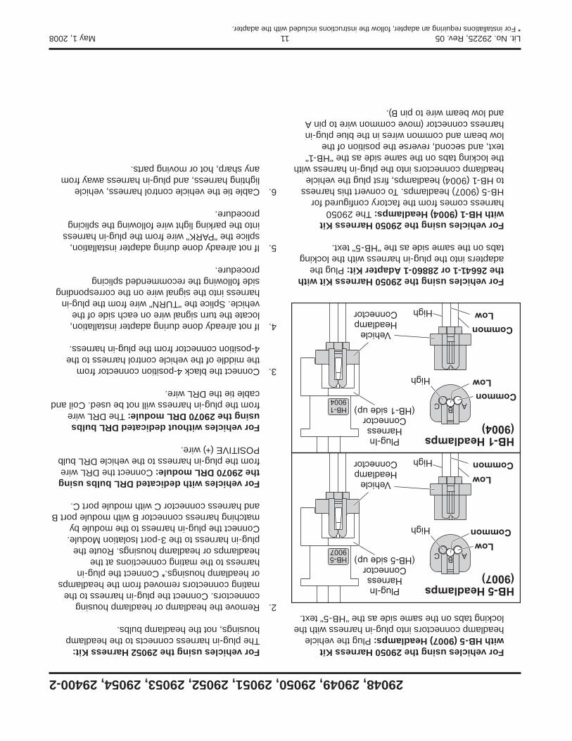
For vehicles using the 29052 Harness Kit: The plug-in harness connects to the headlamp housings, not the headlamp bulbs.
2. Remove the headlamp or headlamp housing connectors. Connect the plug-in harness to the mating connectors removed from the headlamps or headlamp housings.* Connect the plug-in harness to the mating connections at the headlamps or headlamp housings. Route the plug-in harness to the 3-port Isolation Module. Connect the plug-in harness to the module by matching harness connector B with module port B and harness connector C with module port C.
For vehicles with dedicated DRL bulbs using the 29070 DRL module: Connect the DRL wire from the plug-in harness to the vehicle DRL bulb POSITIVE (+) wire.
For vehicles without dedicated DRL bulbs using the 29070 DRL module: The DRL wire from the plug-in harness will not be used. Coil and cable tie the DRL wire.
3. If not already done during adapter installation, locate the turn signal wire on each side of the vehicle. Splice the "TURN" wire from the plug-in harness into the signal wire on the corresponding side following the recommended splicing procedure.
4. If not already done during adapter installation, splice the "PARK" wire from the plug-in harness into the parking light wire following the splicing procedure.
5. Cable tie the vehicle control harness, vehicle lighting harness, and plug-in harness away from any sharp, hot or moving parts. The vehicle control harness and vehicle lighting harness are designed to plug into one another for storage.
* For installations requiring an adapter, follow the instructions included with the adapter.
For vehicles using the 29050 Harness Kit with the 29056-1 Adapter Kit: Connect the 29050 to the HB-5 headlamps on the vehicle. The adapter will connect to the HB-1 headlamps.
For vehicles using the 29050 Harness Kit with HB-5 (9007) Headlamps: Plug the vehicle headlamp connectors into plug-in harness with the locking tabs on the same side as the "HB-5" text.
For vehicles using the 29050 Harness Kit with the 26641-1 or 28860-1 Adapter Kit: Plug the adapters into the plug-in harness with the locking tabs on the same side as the "HB-5" text.
For vehicles using the 29050 Harness Kit with HB-1 (9004) Headlamps: The 29050 harness comes from the factory confi gured for HB-5 (9007) headlamps. To convert this harness to HB-1 (9004) headlamps, fi rst plug the vehicle headlamp connectors into the plug-in harness with the locking tabs on the same side as the "HB-1" text, and second, reverse the position of the low beam and common wires in the blue plug-in harness connector (move common wire to pin A and low beam wire to pin B).
Low
Low
Common
Common
High
High
HB-5 Headlamps(9007)
Plug-InHarness
Connector(HB-5 side up)
VehicleHeadlampConnector
Common
Common
Low
Low
High
High
HB-1 Headlamps(9004)
Plug-InHarness
Connector(HB-1 side up)
VehicleHeadlampConnector
HB-59007
Lit. No.29206, Rev. 05 14 May 1, 2008
29048, 29049, 29050, 29051, 29052, 29053, 29054, 29400-2
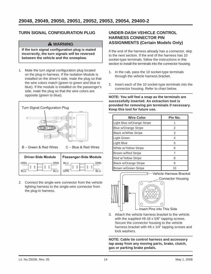
UNDER-DASH VEHICLE CONTROL HARNESS CONNECTOR PIN ASSIGNMENTS (Certain Models Only)
If the end of the harness already has a connector, skip to the next section. If the end of the harness has 10 socket-type terminals, follow the instructions in this section to install the terminals into the connector housing.
1. In the cab, pass the 10 socket-type terminals through the vehicle harness bracket.
2. Insert each of the 10 socket-type terminals into the connector housing. Refer to chart below.
NOTE: You will feel a snap as the terminals are successfully inserted. An extraction tool is provided for removing pin terminals if necessary. Keep this tool for future use.
3. Attach the vehicle harness bracket to the vehicle with the supplied #8-18 x 5/8" tapping screws. Secure the connector housing to the vehicle harness bracket with #6 x 1/4" tapping screws and lock washers.
NOTE: Cable tie control harness and accessory tap away from any moving parts, brake, clutch, gas or parking brake pedals.
WARNINGIf the turn signal confi guration plug is mated incorrectly, the turn signals will be reversed between the vehicle and the snowplow.
TURN SIGNAL CONFIGURATION PLUG
1. Mate the turn signal confi guration plug located on the plug-in harness. If the Isolation Module is installed on the driver's side, mate the plug so that the wire colors match (green to green and blue to blue). If the module is installed on the passenger's side, mate the plug so that the wire colors are opposite (green to blue).
2. Connect the single-wire connector from the vehicle lighting harness to the single-wire connector from the plug-in harness.
Turn Signal Configuration Plug
Driver-Side Module Passenger-Side ModuleGRN GRN
BLU BLU
BLU GRN
GRN BLU
B – Green & Red Wires C – Blue & Red Wires
Insert Pins into This Side
Vehicle Harness BracketConnector Housing
Wire Color Pin No.Light Blue w/Orange Stripe 1Blue w/Orange Stripe 2Black w/White Stripe 3Light Green 4Light Blue 5White w/Yellow Stripe 6Brown w/Red Stripe 7Red w/Yellow Stripe 8Black w/Orange Stripe 9Brown w/Green Stripe 10

Lit. No. 29206, Rev. 05 15 May 1, 2008
29048, 29049, 29050, 29051, 29052, 29053, 29054, 29400-2
BATTERY CABLE CONNECTIONS
Top Post Batteries w/Lead Cable Ends
1. Attach the POSITIVE (+) OEM cable to the battery post. Attach the red battery cable to the bolt in the OEM terminal with original fastener.
2. Attach the NEGATIVE (–) OEM cable to the battery post. Attach the black wire from the vehicle battery cable to the OEM terminal bolt with original fastener.
Top Post Batteries w/Stamped Steel Battery Terminals
Top Post Batteries, Style One
These terminals are secured with a 6mm washer-head cap screw and nut.
1. If the cap screw is long enough for the added thickness of the cable terminal, washer and nut, it will not need to be replaced, and Step 2 may be skipped.
2. Carefully lift retainer tabs (if present), and remove the short cap screw. Insert the supplied longer cap screw through a 3/16" washer and into the hole in the clamp. Carefully bend the retainer tabs back into place.
3. Attach POSITIVE (+) OEM battery clamp to battery post, and secure clamp.
4. Place red battery cable over the end of the battery terminal screw. If added terminal has large contact area with the battery clamp, retain with washer and nut. If the terminal contact area is small (terminal hole almost passes over a 6mm nut), add a washer to both sides of the cable, and secure with a nut.
5. Connect the black wire from the vehicle battery cable and the OEM NEGATIVE (–) cable to the NEGATIVE (–) battery terminal following the same procedure used in Steps 1–4.
Top Post Batteries, Style Two
These terminals are secured with a 6mm tapered nut and cam.
1. Make the connections to the POSITIVE (+) terminal as follows:
a. Remove cable assembly from battery post by loosening the nut. Trim plastic terminal cover as shown.
b. Carefully bend tab securing the cam upward so the cam can be lifted off the stamped terminal after the nut has been removed.
c. Place the red battery cable over the battery terminal screw.
d. Slide the cam over the terminal screw and tab. Reinstall the nut.
e. Place cable assembly on battery post, align red battery cable with the opening in the cover, and tighten nut. Close plastic terminal cover.
2. Make the connections to the NEGATIVE (–) terminal as follows:
a. Remove cable assembly from battery post by loosening the nut.
b. Carefully bend tab securing the cam upward so the cam can be lifted off the stamped terminal after the nut has been removed.
Washer(See Step 4)
Red Battery Cable
Vehicle Cable
BatteryClamp Cap Screw
(See Step 4)
Nut
CamTab
Trim marked areas
Lit. No.29206, Rev. 05 16 May 1, 2008
29048, 29049, 29050, 29051, 29052, 29053, 29054, 29400-2
c. Place the black wire from the vehicle battery cable over the battery terminal screw.
d. Slide the cam over the terminal screw and tab. Reinstall the nut.
e. Place cable assembly on battery post, and tighten nut.
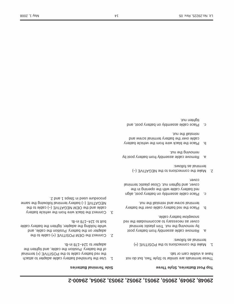
Top Post Batteries, Style Three
These terminals are similar to Style Two, but do not have a visible cam or tab.
1. Make the connections to the POSITIVE (+) terminal as follows:
a. Remove cable assembly from battery post by removing the nut. Trim plastic terminal cover as necessary to accommodate the red snowplow battery cable.
b. Place the red battery cable over the battery terminal screw and reinstall the nut.
c. Place cable assembly on battery post, align red battery cable with the opening in the cover, and tighten nut. Close plastic terminal cover.
2. Make the connections to the NEGATIVE (–) terminal as follows:
a. Remove cable assembly from battery post by removing the nut.
b. Place the black wire from the vehicle battery cable over the battery terminal screw and reinstall the nut.
c. Place cable assembly on battery post, and tighten nut.
Side Terminal Batteries
1. Use the furnished battery cable adapter to attach the red battery cable to the POSITIVE (+) terminal of the battery. Position the cable, and tighten the adapter to 124–178 in-lb.
2. Connect the OEM POSITIVE (+) cable to the adapter on the battery. Position the cable, and while holding the adapter, tighten the battery cable bolt to 124–178 in-lb.
3. Connect the black wire from the vehicle battery cable and the OEM NEGATIVE (–) cable to the NEGATIVE (–) battery terminal following the same procedure used in Steps 1 and 2.

Lit. No. 29206, Rev. 05 17 May 1, 2008
29048, 29049, 29050, 29051, 29052, 29053, 29054, 29400-2
The company reserves the right under its product improvement policy to change construction or design details and furnish equipment when so altered without reference to illustrations or specifi cations used. This equipment manufacturer or the vehicle manufacturer may require or recommend optional equipment for snow removal. Do not exceed vehicle ratings with a snowplow. The company offers a limited warranty for all snowplows and accessories. See separately printed page for this important information.
Printed in U.S.A.

Lit. No. 29225, Rev. 05 15 May 1, 2008
29048, 29049, 29050, 29051, 29052, 29053, 29054, 29400-2
The company reserves the right under its product improvement policy to change construction or design details and furnish equipment when so altered without reference to illustrations or specifi cations used. This equipment manufacturer or the vehicle manufacturer may require or recommend optional equipment for snow removal. Do not exceed vehicle ratings with a snowplow. The company offers a limited warranty for all snowplows and accessories. See separately printed page for this important information.
Printed in U.S.A.
Lit. No.29225, Rev. 05 14 May 1, 2008
29048, 29049, 29050, 29051, 29052, 29053, 29054, 29400-2
Top Post Batteries, Style Three
These terminals are similar to Style Two, but do not have a visible cam or tab.
1. Make the connections to the POSITIVE (+) terminal as follows:
a. Remove cable assembly from battery post by removing the nut. Trim plastic terminal cover as necessary to accommodate the red snowplow battery cable.
b. Place the red battery cable over the battery terminal screw and reinstall the nut.
c. Place cable assembly on battery post, align red battery cable with the opening in the cover, and tighten nut. Close plastic terminal cover.
2. Make the connections to the NEGATIVE (–) terminal as follows:
a. Remove cable assembly from battery post by removing the nut.
b. Place the black wire from the vehicle battery cable over the battery terminal screw and reinstall the nut.
c. Place cable assembly on battery post, and tighten nut.
Side Terminal Batteries
1. Use the furnished battery cable adapter to attach the red battery cable to the POSITIVE (+) terminal of the battery. Position the cable, and tighten the adapter to 124–178 in-lb.
2. Connect the OEM POSITIVE (+) cable to the adapter on the battery. Position the cable, and while holding the adapter, tighten the battery cable bolt to 124–178 in-lb.
3. Connect the black wire from the vehicle battery cable and the OEM NEGATIVE (–) cable to the NEGATIVE (–) battery terminal following the same procedure used in Steps 1 and 2.

Lit. No. 29225, Rev. 05 13 May 1, 2008
29048, 29049, 29050, 29051, 29052, 29053, 29054, 29400-2
Top Post Batteries, Style Two
These terminals are secured with a 6mm tapered nut and cam.
1. Make the connections to the POSITIVE (+) terminal as follows:
a. Remove cable assembly from battery post by loosening the nut. Trim plastic terminal cover as shown.
b. Carefully bend tab securing the cam upward so the cam can be lifted off the stamped terminal after the nut has been removed.
c. Place the red battery cable over the battery terminal screw.
d. Slide the cam over the terminal screw and tab. Reinstall the nut.
e. Place cable assembly on battery post, align red battery cable with the opening in the cover, and tighten nut. Close plastic terminal cover.
Nut
CamTab
Trim marked areas
2. Make the connections to the NEGATIVE (–) terminal as follows:
a. Remove cable assembly from battery post by loosening the nut.
b. Carefully bend tab securing the cam upward so the cam can be lifted off the stamped terminal after the nut has been removed.
c. Place the black wire from the vehicle battery cable over the battery terminal screw.
d. Slide the cam over the terminal screw and tab. Reinstall the nut.
e. Place cable assembly on battery post, and tighten nut.
Lit. No.29225, Rev. 05 12 May 1, 2008
29048, 29049, 29050, 29051, 29052, 29053, 29054, 29400-2
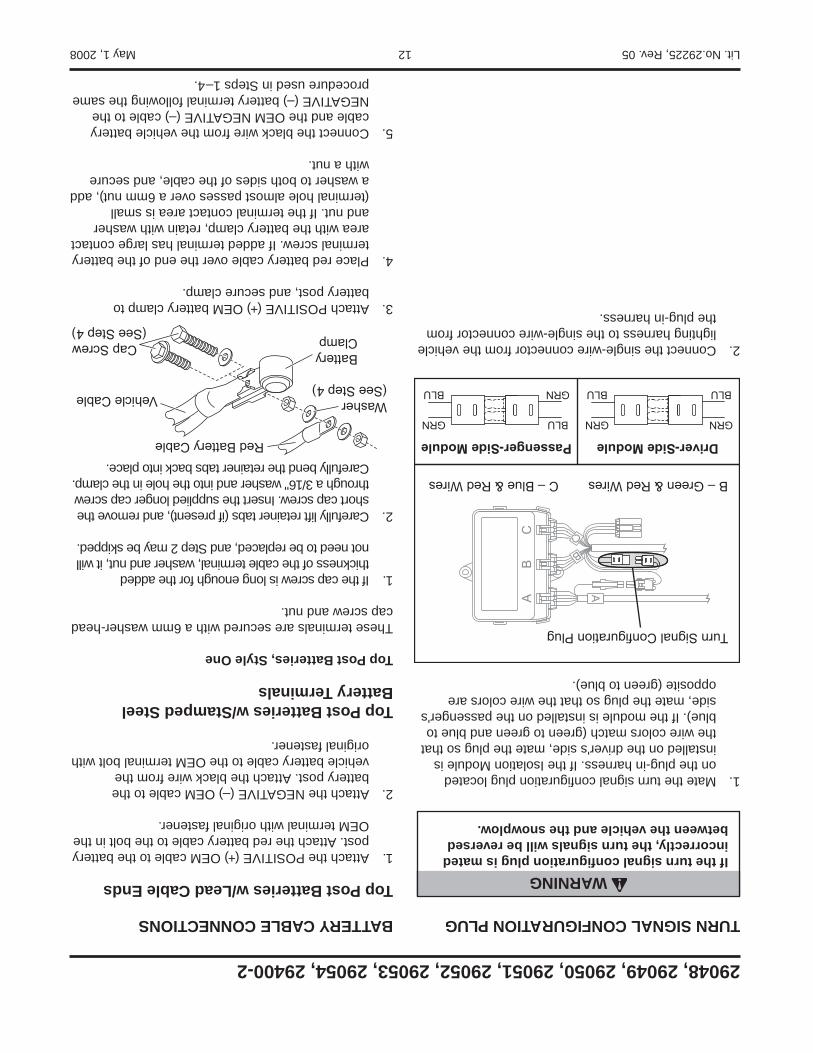
WARNINGIf the turn signal confi guration plug is mated incorrectly, the turn signals will be reversed between the vehicle and the snowplow.
TURN SIGNAL CONFIGURATION PLUG
1. Mate the turn signal confi guration plug located on the plug-in harness. If the Isolation Module is installed on the driver's side, mate the plug so that the wire colors match (green to green and blue to blue). If the module is installed on the passenger's side, mate the plug so that the wire colors are opposite (green to blue).
2. Connect the single-wire connector from the vehicle lighting harness to the single-wire connector from the plug-in harness.
Turn Signal Configuration Plug
Driver-Side ModulePassenger-Side ModuleGRNGRN
BLUBLU
BLUGRN
GRNBLU
B – Green & Red Wires C – Blue & Red Wires
BATTERY CABLE CONNECTIONS
Top Post Batteries w/Lead Cable Ends
1. Attach the POSITIVE (+) OEM cable to the battery post. Attach the red battery cable to the bolt in the OEM terminal with original fastener.
2. Attach the NEGATIVE (–) OEM cable to the battery post. Attach the black wire from the vehicle battery cable to the OEM terminal bolt with original fastener.
Top Post Batteries w/Stamped Steel Battery Terminals
Top Post Batteries, Style One
These terminals are secured with a 6mm washer-head cap screw and nut.
1. If the cap screw is long enough for the added thickness of the cable terminal, washer and nut, it will not need to be replaced, and Step 2 may be skipped.
2. Carefully lift retainer tabs (if present), and remove the short cap screw. Insert the supplied longer cap screw through a 3/16" washer and into the hole in the clamp. Carefully bend the retainer tabs back into place.
3. Attach POSITIVE (+) OEM battery clamp to battery post, and secure clamp.
4. Place red battery cable over the end of the battery terminal screw. If added terminal has large contact area with the battery clamp, retain with washer and nut. If the terminal contact area is small (terminal hole almost passes over a 6mm nut), add a washer to both sides of the cable, and secure with a nut.
5. Connect the black wire from the vehicle battery cable and the OEM NEGATIVE (–) cable to the NEGATIVE (–) battery terminal following the same procedure used in Steps 1–4.
Washer(See Step 4)
Red Battery Cable
Vehicle Cable
BatteryClampCap Screw
(See Step 4)
Lit. No. 29225, Rev. 05 11 May 1, 2008
29048, 29049, 29050, 29051, 29052, 29053, 29054, 29400-2
For vehicles using the 29050 Harness Kit with HB-5 (9007) Headlamps: Plug the vehicle headlamp connectors into plug-in harness with the locking tabs on the same side as the "HB-5" text.
For vehicles using the 29050 Harness Kit with the 26641-1 or 28860-1 Adapter Kit: Plug the adapters into the plug-in harness with the locking tabs on the same side as the "HB-5" text.
For vehicles using the 29050 Harness Kit with HB-1 (9004) Headlamps: The 29050 harness comes from the factory confi gured for HB-5 (9007) headlamps. To convert this harness to HB-1 (9004) headlamps, fi rst plug the vehicle headlamp connectors into the plug-in harness with the locking tabs on the same side as the "HB-1" text, and second, reverse the position of the low beam and common wires in the blue plug-in harness connector (move common wire to pin A and low beam wire to pin B).
HB-59007
Low
Low
Common
Common
High
High
HB-5 Headlamps(9007)
Plug-InHarness
Connector(HB-5 side up)
VehicleHeadlampConnector
Common
Common
Low
Low
High
High
HB-1 Headlamps(9004)
Plug-InHarness
Connector(HB-1 side up)
VehicleHeadlampConnector
For vehicles using the 29052 Harness Kit: The plug-in harness connects to the headlamp housings, not the headlamp bulbs.
2. Remove the headlamp or headlamp housing connectors. Connect the plug-in harness to the mating connectors removed from the headlamps or headlamp housings.* Connect the plug-in harness to the mating connections at the headlamps or headlamp housings. Route the plug-in harness to the 3-port Isolation Module. Connect the plug-in harness to the module by matching harness connector B with module port B and harness connector C with module port C.
For vehicles with dedicated DRL bulbs using the 29070 DRL module: Connect the DRL wire from the plug-in harness to the vehicle DRL bulb POSITIVE (+) wire.
For vehicles without dedicated DRL bulbs using the 29070 DRL module: The DRL wire from the plug-in harness will not be used. Coil and cable tie the DRL wire.
3. Connect the black 4-position connector from the middle of the vehicle control harness to the 4-position connector from the plug-in harness.
4. If not already done during adapter installation, locate the turn signal wire on each side of the vehicle. Splice the "TURN" wire from the plug-in harness into the signal wire on the corresponding side following the recommended splicing procedure.
5. If not already done during adapter installation, splice the "PARK" wire from the plug-in harness into the parking light wire following the splicing procedure.
6. Cable tie the vehicle control harness, vehicle lighting harness, and plug-in harness away from any sharp, hot or moving parts.
* For installations requiring an adapter, follow the instructions included with the adapter.
Lit. No.29225, Rev. 05 10 May 1, 2008
29048, 29049, 29050, 29051, 29052, 29053, 29054, 29400-2
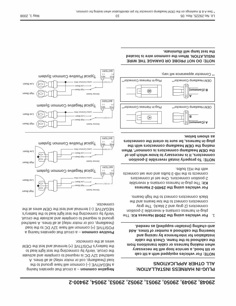
PLUG-IN HARNESS INSTALLATION:ALL OTHER APPLICATIONS
NOTE: For vehicles equipped with a tilt cab or tilt hood, a service loop will be necessary when making harness or cable transitions from the cab/hood to the frame. Check the cable installation for interference by raising and lowering the cab/hood a number of times. Add anti-chafi ng (installer-supplied) as needed.
1. For vehicles using the 29048 Harness Kit: The plug-in harness contains 4 reversible 2-position connectors (2 gray and 2 black). The gray connectors connect to the low beams and the black connectors connect to the high beams.
For vehicles using the 29400-2 Harness Kit: The plug-in harness contains 4 reversible 2-position connectors. One set of connectors connects to the HB-3 bulbs and one set connects with the H11 bulbs.
NOTE: To properly install reversible 2-position connectors, it is necessary to know which pin of the OEM headlamp connectors is common*. When mating the OEM headlamp connectors with the plug-in harness, be sure to orient the connectors as shown below.
NOTE: DO NOT PROBE OR DAMAGE THE WIRE INSULATION. When the common wire is located the test lamp will illuminate.
A (Common)
B
** Connector appearance will vary.
OEM Headlamp Connector**Plug-In Harness Connector**
A
B (Common)
OEM Headlamp Connector**Plug-In Harness Connector**
* See A & B markings on the OEM headlamp connector for pin identifi cation when testing for common.
Negative common – a circuit that operates having a NEGATIVE (–) common will have ground to the load (headlamp, coil or motor relay) at all times. A switched 12V DC is required to complete and activate the circuit. Verify by connecting the test light lead to the battery's POSITIVE (+) terminal and test the OEM wires at the connector.
Positive common – a circuit that operates having a POSITIVE (+) common will have 12V DC to the load (headlamp, coil or motor relay) at all times. A switched ground is required to complete and activate the circuit. Verify by connecting the test light lead to the battery's NEGATIVE (–) terminal and test the OEM wires at the connector.
Typical Negative Common System
Typical Positive Common System
Typical Negative Common System
Typical Positive Common System
High Beam
Low Beam
High Beam
Low Beam
High Beam
Low Beam
High Beam
Low Beam
High Beam
Low Beam
High Beam
Low Beam
High Beam
Low Beam
High Beam
Low Beam
Dimmer Switch
Dimmer Switch
Dimmer Switch
Dimmer Switch
Lamp Common Wire
Lamp Common Wire
Lamp Common Wire
Lamp Common Wire
BATTERY
POS.(+)
NEG.(–)
+12 VOLT
BATTERY
POS.(+)
NEG.(–)
+12 VOLT
BATTERY
POS.(+)
NEG.(–)
+12 VOLT
BATTERY
POS.(+)
NEG.(–)
+12 VOLT

Lit. No. 29225, Rev. 05 9 May 1, 2008
29048, 29049, 29050, 29051, 29052, 29053, 29054, 29400-2
PLUG-IN HARNESS INSTALLATION: VEHICLES USING THE 29053 HARNESS KIT
1. Locate the passenger-side OEM vehicle headlamp connector located near the tilt-hood hinge below the headlamp housing.
2. Remove the small, light gray connector lock by carefully sliding it back away from the connector. Separate the connectors by pushing down on the locking tab and pulling them apart.
3. Connect the plug-in harness female connector to the male OEM vehicle headlamp connector. Reinstall the small, light gray connector lock.
4. Connect the plug-in harness male connector to the female OEM vehicle headlamp connector.
5. Route the remaining half of the plug-in harness to the driver-side OEM vehicle headlamp connector, and repeat Steps 2–4.
6. Route the plug-in harness to the 3-port Isolation Module by running the harness along the existing cables underneath the engine and radiator area. Connect the plug-in harness to the module by matching harness connector B with module port B and harness connector C with module port C.
7. Connect the black 4-position connector from the middle of the vehicle control harness to the 4-position connector from the plug-in harness.
8. Cable tie the vehicle control harness, vehicle lighting harness and plug-in harness away from any sharp, hot or moving parts.
9. Skip ahead to Turn Signal Confi guration Plug section.
PLUG-IN HARNESS INSTALLATION: VEHICLES USING THE 29054 HARNESS KIT
1. Locate the passenger-side OEM vehicle headlamp connector located near the tilt-hood hinge below the headlamp housing.
2. Remove the small, light gray connector lock by depressing the tabs on both sides and pulling outward. Save the connector lock.
3. Disconnect the connector by lifting up on the locking tab and pulling it apart. Carefully unclip the vehicle headlamp harness and reroute it back to the frame, cable tying as necessary.
4. Connect the plug-in harness female connector to the male OEM vehicle headlamp connector. Reinstall the small, light gray connector lock. Route the plug-in harness back toward the frame using existing cable clips.
5. Connect the plug-in harness male connector to the female OEM vehicle headlamp connector.
6. Route the plug-in harness to the 3-port Isolation Module. Connect the plug-in harness to the module by matching harness connector B with module port B and harness connector C with module port C.
7. Connect the black 4-position connector from the middle of the vehicle control harness to the 4-position connector from the plug-in harness.
8. Cable tie the vehicle control harness, vehicle lighting harness and plug-in harness away from any sharp, hot or moving parts.
9. There is no turn signal confi guration plug on this harness. Skip ahead to Under-Dash Vehicle Control Harness Connector Pin Assignments section.

Lit. No.29225, Rev. 05 8 May 1, 2008
29048, 29049, 29050, 29051, 29052, 29053, 29054, 29400-2
9. Check circuits for continuity.
10. Cover the splice with heatshrink tubing. The tubing should extend beyond the splice on both sides.
11. Using a hot air source, starting in the center and working to either side, apply heat until the tubing recovers and glue can be seen around the edges. Allow the tubing to cool before handling.
NOTE: The splices supplied will accommodate 18-gauge wires as shown. For larger gauge wires, cut the wire, strip the ends 3/8" to 1/2", and twist together. Apply solder to the splice and cover with heatshrink tubing.
Crimp and solder each splice.
Cover the splice with heatshrink tubing. Using a hot air source, apply heat until tubing
recovers and glue can be seen around the edges. Allow tubing to cool before handling.
From park, turn, or DRLlamp
From OEMvehicle harnessFrom plug-inharness
Splicing Procedure
Butt Splice
5/16"
Insert wires into splice.
Heatshrink tubing Glue
RECOMMENDED SPLICING PROCEDURE
1. Locate wire to be spliced into.
2. Cut wire at least 1-1/2" from any other splice, connector, or terminal. If wires are covered by tubing or braid, remove enough of it to achieve the minimum clearance required.
3. Strip away 5/16" of the insulation from the ends of the wires to be spliced.
4. Slide two wires into one end of the supplied parallel splice.
5. Place a piece of heatshrink tubing (3/16" x 1-1/4" long) over the remaining wire to be spliced. Cut tubing into 1-1/4" lengths if required.
6. Insert wire into the open end of the splice and crimp using an appropriate crimp tool. One or two crimps may be necessary to ensure a good connection. No wire strands should be visible outside of the splice.
7. Preheat a soldering tool for at least one minute to help promote even solder fl ow.
8. Apply heat to the splice. Avoid heating too close to the insulation. Apply solder to the wires. Use just enough solder to produce an even fl ow through the splice. Use rosin core solder ONLY. Do not use acid core solder.
NOTE: Avoid using an excessive amount of solder as it can result in wicking. Wicking occurs when solder travels up the wire core. This may cause the wire to become stiff or brittle which could lead to a broken or open circuit.
Lit. No. 29225, Rev. 05 7 May 1, 2008
29048, 29049, 29050, 29051, 29052, 29053, 29054, 29400-2
VEHICLE LIGHTING AND VEHICLE CONTROL HARNESS INSTALLATION
NOTE: For vehicles equipped with a tilt cab or tilt hood, a service loop will be necessary when making harness or cable transitions from the cab/hood to the frame. Check the cable installation for interference by raising and lowering the cab/hood a number of times. Add anti-chafi ng material (installer-supplied) as needed.
1. Route both harnesses around or through the radiator bulkhead to the Isolation Module.
2. Connect the vehicle lighting harness to position A on the 3-port Isolation Module.*
3. Route the end of the vehicle control harness with the white, 4-pin connector to the fi re wall.
4. Connect the black 4-position connector (labeled "BAT") from the end of the vehicle control harness to the 4-position connector from the vehicle battery cable. Do not cable tie the harness at this time.
5. On the driver's side, locate an existing hole through the fi re wall for the vehicle control harness. If access through the fi re wall does not exist, drill a 5/8" hole through the fi re wall of the vehicle in a convenient location away from sharp edges, and hot or moving parts.
*For installations requiring an adapter, follow the instructions included with the adapter.
6. Push the braided harness breakout with the cab control connector through the fi re wall hole into the cab. Use a grommet, existing plug cover, or proper chafi ng material to protect the harness where it passes through the fi re wall. Route the harness to the selected control mounting location. To mount the control, follow the instructions supplied with the control.
7. Locate an accessory wire controlled by the ignition switch. Acceptable accessory wires show +12V when the ignition switch is ON, and 0V when it is OFF.
8. Route the red "ACC" wire from the vehicle control harness to this location and trim away excess length.
9. Following the recommended splicing procedure, splice the red "ACC" wire into the switched accessory wire using the supplied parallel splices and heatshrink tubing.
CAUTIONBefore installing self-drilling screws or drilling mounting holes, check the selected mounting area for any wires, hoses, or other obstructions.

Lit. No.29225, Rev. 05 6 May 1, 2008
29048, 29049, 29050, 29051, 29052, 29053, 29054, 29400-2
INSTALLATION OF 3-PORT ISOLATION MODULE PN 29760-1
Due to the high temperature found in the engine compartments of some 2008 and later Ford Super Duty trucks, mounting the module behind the driver-side headlamp housing is required. Failure to do so may cause the Isolation Module to fail.
1. The module must be secured to the headlamp mounting bracket by installing reclosable fastener strips to the edge and wrapping cable ties around the module so it can be secured to the rear of the headlamp mounting bracket.
Reclosable Fastener Strip
Secure cable tie here.
2. Be sure to position the module between the headlamp alignment pinholes and maintain a small air gap behind the Isolation Module.
Reclosable Fastener Strip
Route cable tiethrough this loop.
Two cable ties
ReclosableFastenerStrip
Lit. No. 29225, Rev. 05 5 May 1, 2008
29048, 29049, 29050, 29051, 29052, 29053, 29054, 29400-2
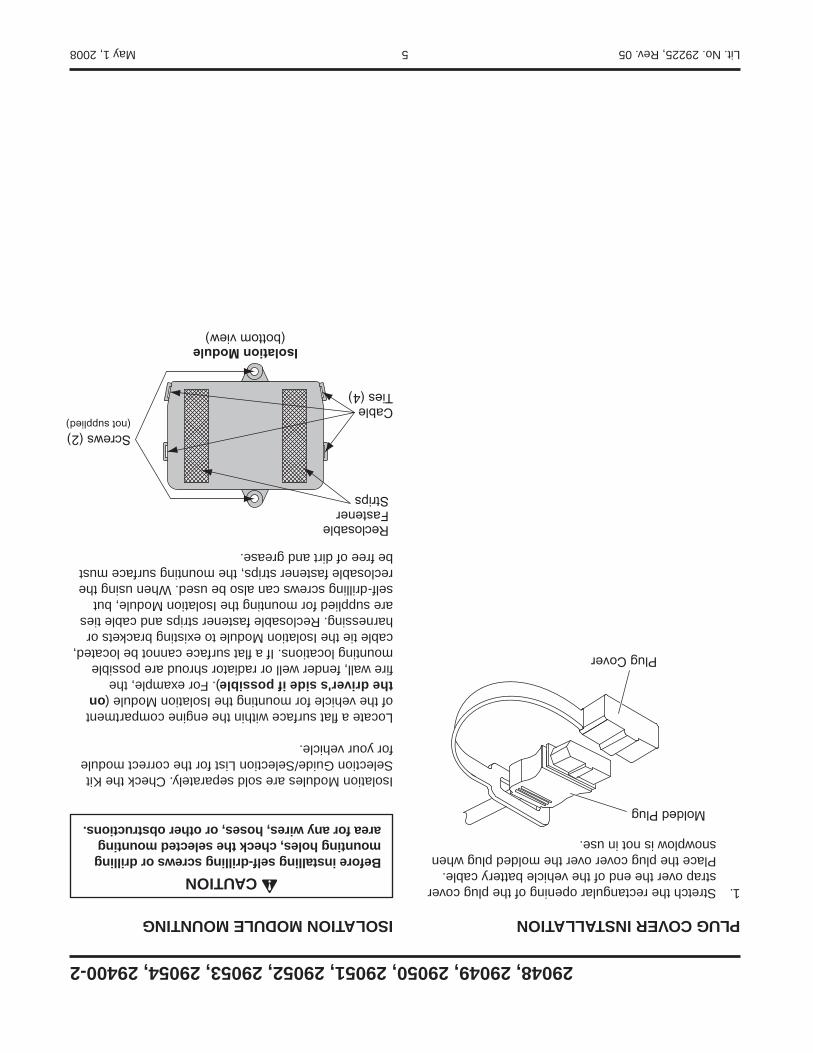
ISOLATION MODULE MOUNTING
Isolation Modules are sold separately. Check the Kit Selection Guide/Selection List for the correct module for your vehicle.
Locate a fl at surface within the engine compartment of the vehicle for mounting the Isolation Module (on the driver's side if possible). For example, the fi re wall, fender well or radiator shroud are possible mounting locations. If a fl at surface cannot be located, cable tie the Isolation Module to existing brackets or harnessing. Reclosable fastener strips and cable ties are supplied for mounting the Isolation Module, but self-drilling screws can also be used. When using the reclosable fastener strips, the mounting surface must be free of dirt and grease.
CableTies (4)
ReclosableFastenerStrips
Isolation Module(bottom view)
Screws (2)(not supplied)
CAUTIONBefore installing self-drilling screws or drilling mounting holes, check the selected mounting area for any wires, hoses, or other obstructions.
PLUG COVER INSTALLATION
1. Stretch the rectangular opening of the plug cover strap over the end of the vehicle battery cable. Place the plug cover over the molded plug when snowplow is not in use.
Molded Plug
Plug Cover

Lit. No.29225, Rev. 05 4 May 1, 2008
29048, 29049, 29050, 29051, 29052, 29053, 29054, 29400-2
VEHICLE BATTERY CABLE INSTALLATION
NOTE: When instructed, make all snowplow battery cable connections to the auxiliary battery, if vehicle is so equipped.
NOTE: For vehicles equipped with a tilt cab or tilt hood, a service loop will be necessary when making harness or cable transitions from the cab/hood to the frame. Check the cable installation for interference by raising and lowering the cab/hood a number of times. Add anti-chafi ng material (installer-supplied) as needed.
1. Turn off the vehicle ignition.
2. Disconnect both the NEGATIVE (–) and the POSITIVE (+) battery cables.
3 Route the supplied vehicle battery cable from the grille or bumper to the battery, avoiding any sharp edges and hot or moving parts. Cable tie only the end section closest to the grille. Lengthening the vehicle battery cable may be necessary on vehicles with batteries located under or behind the
CAUTIONBatteries normally produce explosive gases which can cause personal injury. Therefore, do not allow fl ames, sparks or lit tobacco to come near the battery. When charging or working near a battery, always cover your face and protect your eyes, and also provide ventilation.Batteries contain sulfuric acid which burns skin, eyes and clothing. Disconnect the battery before removing or replacing any electrical components.
cab. If lengthening cables is necessary, use the supplied isolated stud junction block. Mount the block to a fl at surface within reach of the vehicle battery cable, and connect both the vehicle battery cable and the supplied 50" or 90" battery cable to the junction block.
4. Route the red wire from the vehicle battery cable (or 50"/90" battery cable) to the POSITIVE (+) battery terminal. Do not connect at this time.
NOTE: Use dielectric grease on all electrical connections to prevent corrosion. Fill receptacles and lightly coat ring terminals and blades before assembly.
5. Route the black wire from the vehicle battery cable to the NEGATIVE (–) battery terminal. Do not connect at this time. On vehicles with the batteries located under or behind the cab, connect the black wire from the vehicle battery cable to the frame using an existing hole or ground bolt. Prior to attaching, clean away any paint or dirt to ensure a good ground connection. The 4-position connector from the vehicle battery cable will connect to the mating connector (labeled "BAT") on the end of the vehicle control harness.
50" or 90"Battery Cable
VehicleBattery Cable
Isolated StudJunction Block
Lit. No. 29225, Rev. 05 3 May 1, 2008
29048, 29049, 29050, 29051, 29052, 29053, 29054, 29400-2
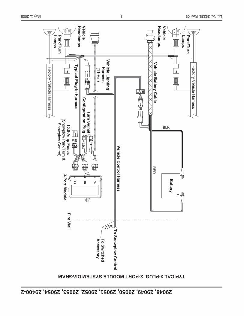
TYPICAL 2-PLUG, 3-PORT MODULE SYSTEM DIAGRAM
Battery
10.0-Am
p Fuses(S
nowplow
Park/Turn &
Snow
plow C
ontrol)
Turn Signal C
onfiguration Plug
Typical Plug-In Harness
Vehicle LightingH
arness(11-P
in)
Vehicle Control H
arness
VehicleH
eadlamps
Park/TurnLam
ps
VehicleH
eadlamps
Park/TurnLam
ps
Factory Vehicle H
arness
Factory Vehicle H
arness
Vehicle Battery C
able
To Snowplow
Control
To Switched
Accessory
Fire Wall
3-Port Module
BAT
RE
D
BLK
RED
Lit. No.29225, Rev. 05 2 May 1, 2008
29048, 29049, 29050, 29051, 29052, 29053, 29054, 29400-2
NOTE: Indicates a situation or action that can lead to damage to your snowplow and vehicle or other property. Other useful information can also be described.
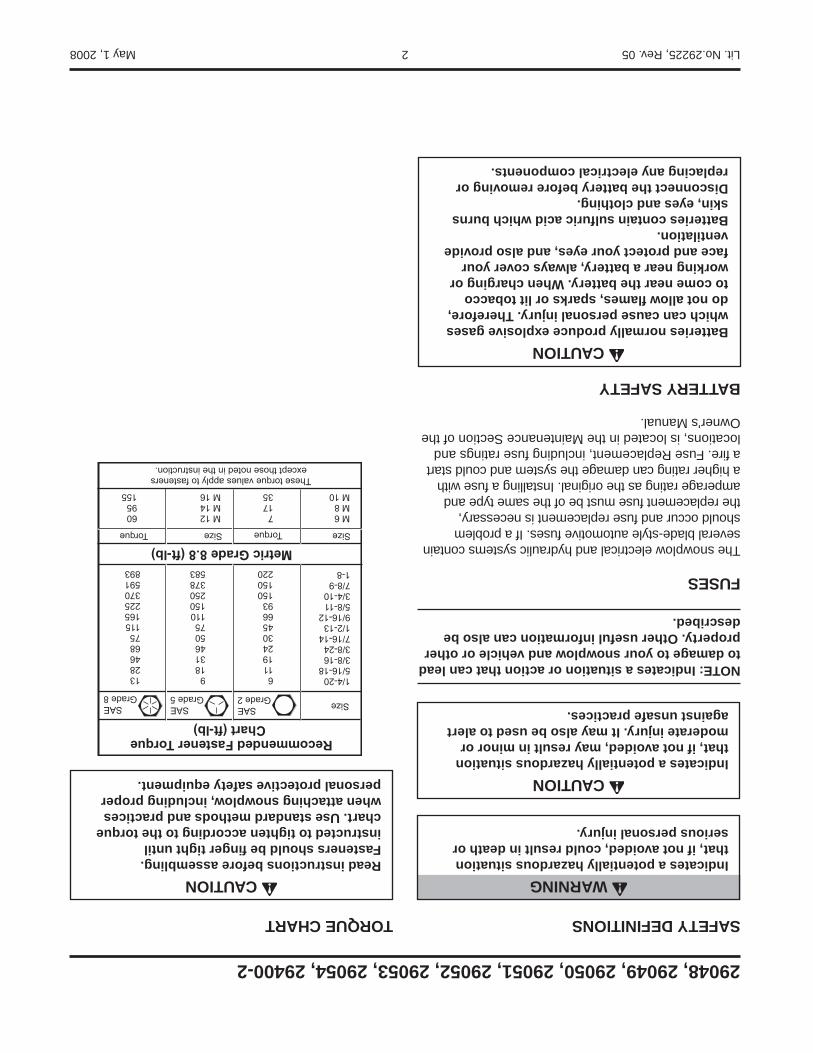
FUSES
The snowplow electrical and hydraulic systems contain several blade-style automotive fuses. If a problem should occur and fuse replacement is necessary, the replacement fuse must be of the same type and amperage rating as the original. Installing a fuse with a higher rating can damage the system and could start a fi re. Fuse Replacement, including fuse ratings and locations, is located in the Maintenance Section of the Owner's Manual.
BATTERY SAFETY
SAFETY DEFINITIONS
CAUTIONIndicates a potentially hazardous situation that, if not avoided, may result in minor or moderate injury. It may also be used to alert against unsafe practices.
TORQUE CHART
Recommended Fastener Torque Chart (ft-lb)
SizeSAEGrade 2
SAEGrade 5
SAEGrade 8
1/4-205/16-183/8-163/8-247/16-141/2-139/16-125/8-113/4-107/8-91-8
611192430456693150150220
91831465075110150250378583
1328466875115165225370591893
Metric Grade 8.8 (ft-lb)SizeTorque Size Torque
M 6M 8M 10
M 12M 14M 16
71735
6095155
These torque values apply to fastenersexcept those noted in the instruction.
CAUTIONRead instructions before assembling. Fasteners should be fi nger tight until instructed to tighten according to the torque chart. Use standard methods and practices when attaching snowplow, including proper personal protective safety equipment.
WARNINGIndicates a potentially hazardous situation that, if not avoided, could result in death or serious personal injury.
CAUTIONBatteries normally produce explosive gases which can cause personal injury. Therefore, do not allow fl ames, sparks or lit tobacco to come near the battery. When charging or working near a battery, always cover your face and protect your eyes, and also provide ventilation. Batteries contain sulfuric acid which burns skin, eyes and clothing. Disconnect the battery before removing or replacing any electrical components.
A DIVISION OF DOUGLAS DYNAMICS, L.L.C.
May 1, 2008Lit. No. 29225, Rev. 05
CAUTIONRead this document before installing the snowplow.
CAUTIONSee your sales outlet/Web site for specifi c vehicle application recommendations before installation. The Kit Selection Guide/Selection List has specifi c vehicle and snowplow requirements.
29048, 29049, 29050, 29051, 29052, 20953, 29054, 29400-2
HARNESS KIT3-PORT ISOLATION MODULE
LIGHT SYSTEM
w/2-PLUG SYSTEM HARNESSES
Installation Instructions