Embed Size (px)
Citation preview

14 TRANSPORTATION RESEARCH RECORD 1286
Aggregate Interlock: A Pure-Shear Load Transfer Mechanism
ANASTAs1os M. loANNIDES AND GEORGE T. KoRovEs1s
A finite element investigation was made of the behavior of jointed or cracked pavement systems equipped with a pure-shear load transfer mechanism, such as aggregate interlock. Dimensional analysis was used in the interpretation of the data, leading to a general definition of lhe relative joint stiffness of the pavement system in terms of its structural characteristics. Results obtained in this study were verified by comparisons with earlier published field, laboratory, and analytical information. The investigation demonstrated that deflection load transfer efficiency is related to stress load transfer efficiency and that this relationship is sensitive to the size of the applied loading (or to the gear configuration). A simple back calculation procedure is outlined to evaluate the in situ joint stiffness of such pavements. Pure-shear load transfer devices are shown to be particularly desirable under a combined externally applied and thermal loading condition, since they offer no additional restraint to longitudinal curling.
Aggregate interlock is a natural mechanism effective in transferring loads across discontinuities, such as joints and cracks, in plain or reinforced Portland cement concrete pavement systems. Only a shear action is operative in this mechanism. In contrast, load transfer devices such as dowel bars also involve bending, thus creating an interest to investigate load transfer by aggregate interlock. This mechanism is easier to model and analyze than, say , a doweled system. Furthermore , its study can provide useful information on alleviating certain ill side effects resulting from the use of bending action load transfer mechanisms , such as additional restraint to longitudinal curling. Finally, interpretation of numerical results obtained from the simpler shear-only devices can suggest methods for handling data pertaining to the more complex case of doweled pavement systems. A finite element investigation is presented to provide a better understanding of the most significant aspects of load transfer in slab-on-grade pavements, when this does not involve bending action .
Because of its questionable long-term endurance record , aggregate interlock is not relied on as a primary load transfer mechanism, except perhaps in low-volume roads . Abrasion and attrition of the aggregates, coupled with temperature variations causing a fluctuation in the size of the opening at the discontinuity, can result in a significant decrease in the effectiveness of this mechanism over time. This deterioration, however , does not detract from the value of a research effort such as is described below. Even for doweled pavement, "the current concept [is] th<1t lo<irl is trnnsferrecl across a joint prin-
A. M. loannides, Department of Civil Enginee ring, University of Illinois, 205 N. Mathews Ave., Urbana, Ill. 61801. G . T. Korovesis, PCS/Law Engineering, 12240 Indian Creek Ct., Suite 120, Beltsville , Md. 20705-1242.
cipally by shear ... l whereas J moment transfer across joints with visible openin_gs is negligible" U ,2).
1 he finite e1ement computer program ILLI-SLAB (3 ,4) was used in this study. This program has been thoroughly checked for accuracy and reliability. It has been adapted recently to permit analysis of multiple-slab systems under combined externally applied and thermal loads (5). Aggregate interlock (or any pure-shear device, in general) is modeled in ILLISLAB by a set of linear springs, acting at each node along the discontinuity. The spring constant assigned, therefore, is indicative of the stiffness of the joint, which is itself a function of joint width , as well as aggregate angularity and hardness . This model is similar to that employed in comparable codes, such as J-SLAB (6) and WESLIQID (7).
Numerical data are interpreted by using the principles of dimensional analysis (8). This approach offers an attractive, often superior, alternative to the more conventional statistical interpretation techniques. As demonstrated in this paper , the considerable progress achieved in understanding load transfer systems, and in compromising apparently conflicting evidence in the technical literature, confirms the validity of this assertion.
EFFICIENCY AND ENDURANCE OF JOINTS
Aggregate interlock was first recognized as a beneficial load transfer mechanism in the early 1900s, when the popularity of Portland cement concrete as a paving material was beginning to increase. The first major field tests and other investigations seeking to provide a better understanding of pavement behavior, thereby leading to improved designs, also date from that time . The Bates Road Test, conducted near Bates, Ill. , between 1921 and 1923 (9), led to the conclusion that once cracks had formed in plain concrete, they tended to propagate rapidly and deteriorate badly under a small number of load repetitions (10). In contrast, cracks developing in reinforced concrete pavement sections remained tight, deteriorated slowly, and exhibited overall much better behavior.
The issue of long-term endurance of natural aggregate interlock has been addressed by subsequent studies as well. In an extensive field investigation conducted by the Michigan State Highway Department in the early 1930s, the superior performance of reinforced sections (in which cracks were held tight) was confirmed, under both a single , as well as repeated , load applications. Therefore it was concluded that "when roughened edges of two slabs are held firmly together the aggregate interlock may be expected to function perfectly and permanently as a load-transfer medium" (11). Seasonal variations

Ioannides and Korovesis
in the efficiency of load transfer at the cracks were also noted. These were the result of expansion of the slabs in the summer and their corresponding contraction in the winter. Joint opening was clearly established as a major determinant of aggregate interlock and efficiency of load transfer. The recommendation to use short slabs with reinforcement to keep tight any cracks that may develop (JO) aimed at ensuring both initial load transfer efficiency (by "lessening the probability of erratic cracking") and better long-term endurance of the joints.
The Arlington load tests (12), on the other hand, led to the conclusion that
aggregate interlock cannot be depended upon to control load stre ses. Even when joints are held closed by bonded steel bars there is a wide variation in the v;1Jue of the critical stress caused by a given load, from side to side of the joint and from point to point along it. For this rea ·on it appears necessary to provide independent means for load tran fer.
This constituted an implicit call for the use of dowels as load transfer devices, in view of the unreliability and variability of aggregate interlock. A fresh look at the Arlington conclusions is offered by the data obtained in this study.
The importance of achieving a satisfactory degree of load transfer at first loading, as well as maintaining this standard over a large number of load applications, was a primary motivation for the comprehensive laboratory study by Colley and Humphrey (13) . These investigators introduced the Endurance Index (El) as a descriptor of long-term joint performance. Expressed as a percentage, this value was defined as the ratio of the area under the curve of joint effectiveness (Eff) versus the number of repetitions (N) to the corresponding area under the curve obtained by setting Eff equal to 100 percent for N = 1 x 10⁶ cycles. The joint effectiveness was defined as follows:
2 6.u Eff = * 100 percent
fl u + flL (1)
where flu and flL are the deflections on the unloaded and the loaded side of the joint or crack, respectively.
Their laboratory tests examined five factors considered important to both EI and Eff, namely , joint width (w); slab thickness (h ); load magnitude (P); foundation type and sub grade modulus (k); and shape of aggregate. Slabs were tested on an unprotected silty-clayey soil (k = 89 psi/in.), as well as on the same subgrade covered with a 6-in. base, consisting of either sandy gravel (k = 145 psi/in .) or a cement-treated material (k = 452 psi/in.). The composite subgrade modulus values quoted were averages from 24-in.-diameter plate load tests. Results confirmed that Eff decreases as w increases, or as N increases, with about 90 percent of the loss occurring during the first 500,000 repetitions. In addition, EI is improved considerably as k increases. Both Eff and EI deteriorate as P increases above some critical value, suggesting that "light loads cause little or no wear and probably do not need to be considered." More angular aggregates resulted in better longterm performance, as expected. Similarly, thicker slabs exhibited higher Eff and EI values than thinner ones.
Following the advent of nondestructive testing (NDT) methods in recent years, attention has also been directed to field evaluation of the load transfer performance of joints and
15
cracks. The falling weight deflectometer (FWD) has been a popular choice for this purpose, with the recommendation for more sensitive sensors to detect small differences in deflection across the discontinuity tested (14) . Result to date (L5) suggest that an increase in amhient temperature improves the efficiency of joints or cracks that are free to open or close. This had also been the conclusion of earlier studies not involving the FWD (11,16).
ENGINEERING INDEPENDENT VARIABLES
The preceding discussion shows that the number of parameters involved in the problem under investigation is large. A factorial designed on the basis of the assumption that the effects of each of these is independent of the others would be prohibitively extensive. It is true that in a finite element investigation such as is described below several factors that are important in the field cannot be explicitly accounted for. Using the Aggregate Interlock Option in ILLI-SLAB, for example, it is not possible to study the effect of the number of load applications (N) on long-term endurance or the effect of aggregate characteristics on joint effectiveness. Even joint width can be incorporated only indirectly in the selection of the spring constant (AGG) used to represent the shear stiffness per unit length of the joint. This constant is also commonly referred to as the aggregate interlock factor (AIF). Empirical relations are, therefore , necessary to fill these and other analytical gaps. Yet, even for an idealized and simplified problem, such as is posed by an ILLI-SLAB run , a methodology is required for designing a short but effective factorial of runs and for interpreting the results obtained so that broad conclusions may be reached. Previous investigations at the University of Illinois have demonstrated the efficacy of dimensional analysis for this purpose.
In previous analytical studies involving a single slab under a single-wheel load, the following nondimensional engineering independent variables have been established:
1. The load size ratio (all), where a is the radius of the applied load and l is the radius of relative stiffness of the slabfoundation system (17);
2. The slab size ratios (Lil and WI!), where L and W are the length and width of the slab, respectively (18,19); and
3. The temperature differential parameter (aflT) in which a is the coefficient of linear expansion of the slab material and flT is the temperature differential between the top and the bottom of the slab (20).
The effect of dual-wheel loads (and, by implication , of multiple-wheel loads, in general) may be quantified by the spacing ratio Sia, where Sis the distance between the wheels (21). This gives rise to the equivalent single axle radius (ESAR) concept, which would allow the application of results obtained from single-wheel load studies to cases involving more complex gear configurations (20). Recent efforts have shown that it is possible to derive with reasonable accuracy an ESAR for any arbitrary loading gear configuration simply as a function of its geometry (size and spacing of tire prints) . The loss of accuracy involved in such a transformation from a multipleto a single-wheel load is the topic of an ongoing investigation at the University of Illinois.

16
It is essential to establish the form of the nondimensional engineering independent variable(s) governing the behavior of a two-slab system equipped with a pure-shear load transfer mechanism, such as aggregate interlock. A procedure suggested by Langhaar (22) may be used for this purpose. The only additional input parameter entering a typical ILLI-SLAB run involving aggregate interlock is AGG, whose dimensions are Fl. - 2 . To form a nondimensional product ('1T), AGG must be combined with one or more other input parameters, which include force (F) and length (L) in their dimensions. To reduce the number of choices further, it is pertinent to recall that AGG is a stiffness term. It is, therefore. reasonable to consider, at least to begin with, other stiffness terms. Clearly, the subgrade modulus (k) and the radius of relative stiffness (/) are ideal choices, since they also possess the necessary dimensions.
Now, any product ('1T) of the.se three parameters will have the following form:
'lT = km' [ml AGG"'3 (2)
The corresponding dimensions of 'lT are
'lT = (FL - 3)"' 1 (L)"'' (FL - 2)"' i (3)
To obtain a dimensionless product, the exponents of F and L must be zero. Thus
(4)
(5)
Assuming that m3 = 1, a solution of the above system of equations is obtained for m, = m2 = -1. Thus, the resulting dimensionless variable is AGGI kl. This variable expresses the relative stiffness of the joint itself to the stiffness of the pavement system in which it is installed. It is interesting to observe that 1/kl was identified as a pertinent lumped variable form by Tabatabaie and Barenberg (3).
Note that the formal procedure outlined by Langhaar (22) and applied above in writing and in solving equations 2 through 5 guarantees neither the uniqueness nor the suitability of the derived dimensionless variable. Like many other engineering aids (e.g., computers, statistics, and the finite element method), dimensional analysis is merely a tool. Fruitful implementation of this type of analysis demands considerable engineering judgment, imagination, and experience. It is primarily on the basis of engineering intuition that the three parameters in Equation 2 were selected in the first place. Furthermore, the weight of the numerical evidence presented below confirms the correctness and adequacy of the dimensionless variable selected. Although the formal derivation outlined above is the most appropriate way of presenting results in a paper, it is rare that one arrives at the most suitable form of the dimensionless variable a priori. More often than not, this is a painstaking trial-and-error procedure, concealed perhaps by the brevity demanded by technical journals. The satisfaction of finally establishing the most general form, and the resulting immense simplification of the problem, provide the fuel that sustains the student of dimensional analysis.
TRANSPORTATION RESEARCH RECORD 1286
DIMENSIONLESS RESPONSE VARIABLES
The three primary response parameters in the analysis of slabon-grade pavement systems are deflection (8), bending stress (CT), and subgrade stress (q). When the dense liquid foundation model is adopted, the latter may be eliminated because
q = k8 (6)
Several dimensionless combinations of the first two response parameters have been proposed in the technical literature as measures of the load transfer efficiency developing in multiple-slab systems. The large number of definitions for the term joint effectiveness is because some definitions may not be appropriate or even correct, particularly when field measurements are considered. In the analytical study presented in this paper no such complications arose, since each definition may be transformed in an algebraically exact manner into any other. Nonetheless, the results justify to a considerable extent the concerns expressed by previous investigators about some definitions. Most of these pertain to the sensitivity of field measuring devices and the impact of relatively minor changes in measured responses.
The definitions adopted in the interpretation of the finite element data presented below are as follows:
• Deflection load transfer efficiency (L TE5) (often abbreviated simply load transfer efficiency or LTE):
llu L TE5 = L TE = ~ x 100 percent
L
•Stress load transfer efficiency (LTE""):
L TE" = CT u x 100 percent CT L
•Transferred load efficiency (TLE):
PT TLE = p x 100 percent
where
(7)
(8)
(9)
CT u, CT L slab bending stress on the unloaded and on the loaded side of a joint or crack, respectively;
PT = total load transferred from the loaded to the unloaded side of a joint or crack, along its entire length; and
P = total externally applied load.
FINITE ELEMENT INVESTIGATION
The problem under investigation is fairly complex, even after the simplifying assumptions of linear elasticity, plate theory, and dense liquid foundation have been adopted. The purpose of these idealizations is to reduce the number of variables involved and thus improve the engineer's ability to understand, if not solve, the problem. Nonetheless, even in the idealized model there is a prohibitively large number of pos-
loannides and Korovesis 17
100
80
,,---..._ 60 ~ '--'
ro w I- 40 __)
20
0 10 - 3 1 0 - 2 1 0 _, 10 ° 10 1 10 2 10 3 10 4
Nond imensional Stiffness (AGG/kQ)
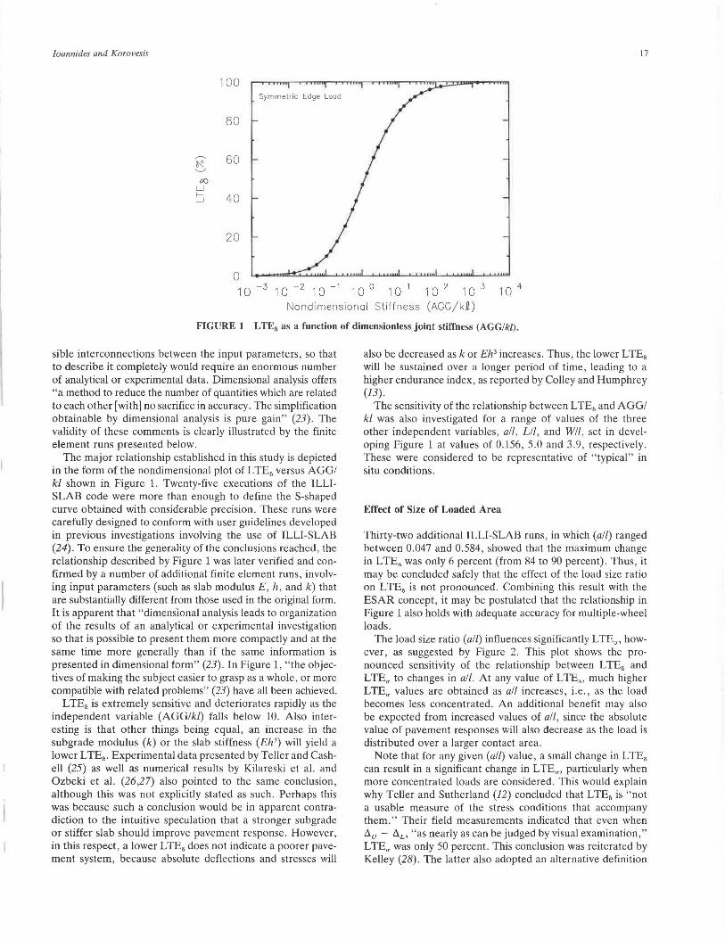
FIGURE 1 L TE6 as a function of dimensionless joint stiffness (AGGI kl).
sible interconnections between the input parameters, so that to describe it completely would require an enormous number of analytical or experimental data. Dimensional analysis offers "a method to reduce the number of quantities which are related to each other [with] no sacrifice in accuracy. The simplification obtainable by dimensional analysis is pure gain" (23). The validity of these comments is clearly illustrated by the finite element runs presented below.
The major relationship established in this study is depicted in the form of the nondimensional plot of L TE6 versus AGGI kl shown in. Figure 1. Twenty-five executions of the ILLISLAB code were more than enough to define the S-shaped curve obtained with considerable precision. These runs were carefully designed to conform with user guidelines developed in previous investigations involving the use of ILLI-SLAB (24). To ensure the generality of the conclusions reached, the relationship described by Figure 1 was later verified and confirmed by a number of additional finite element runs, involving input parameters (such as slab modulus E, h, and k) that are substantially different from those used in the original form. It is apparent that "dimens"ional analysis leads to organization of the results of an analytical or experimental investigation so that is possible to present them more compactly and at the same time more generally than if the same information is presented in dimensional form" (23). In Figure 1, "the objectives of making the subject easier to grasp as a whole, or more compatible with related problems" (23) have all been achieved.
L TE8 is extremely sensitive and deteriorates rapidly as the independent variable (AGGlkl) falls below 10. Also interesting is that other things being equal, an increase in the subgrade modulus (k) or the slab stiffness (Eh3 ) will yield a lower L TE8 • Experimental data presented by Teller and Cashell (25) as well as numerical results by Kilareski et al. and Ozbeki et al. (26,27) also pointed to the same conclusion, although this was not explicitly stated as such. Perhaps this was because such a conclusion would be in apparent contradiction to the intuitive speculation that a stronger subgrade or stiffer slab should improve pavement response. However, in this respect, a lower LTE8 does not indicate a poorer pavement system, because absolute deflections and stresses will
also be decreased ask or Eh3 increases. Thus, the lower LTE8
will be sustained over a longer period of time, leading to a higher endurance index, as reported by Colley and Humphrey (13).
The sensitivity of the relationship between LTE8 and AGGI kl was also investigated for a range of values of the three other independent variables, all, Lil, and WI!, set in developing Figure 1 at values of 0.156, 5.0 and 3.9, respectively . These were considered to be representative of "typical" in situ conditions.
Effect of Size of Loaded Area
Thirty-two additional ILLI-SLAB runs, in which (all) ranged between 0.047 and 0.584, showed that the maximum change in LTE8 was only 6 percent (from 84 to 90 percent) . Thus, it may be concluded safely that the effect of the load size ratio on LTE8 is not pronounced. Combining this result with the ESAR concept, it may be postulated that the relationship in Figure 1 also holds with adequate accuracy for multiple-wheel loads.
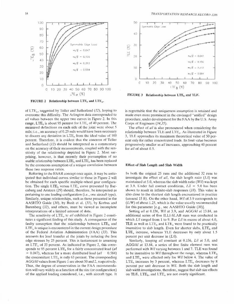
The load size ratio (all) influences significantly LTE.,., however, as suggested by Figure 2. This plot shows the pronounced sensitivity of the relationship between LTE8 and LTE.,. to changes in all. At any value of LTE8 , much higher LTE.,. values are obtained as all increases, i.e., as the load becomes less concentrated. An additional benefit may also be expected from increased values of all, since the absolute value of pavement responses will also decrease as the load is distributed over a larger contact area.
Note that for any given (all) value, a small change in LTE8
can result in a significant change in LTE.,., particularly when more concentrated loads are considered . This would explain why Teller and Sutherland (12) concluded that LTE8 is "not a usable measure of the stress conditions that accompany them." Their field measurements indicated that even when du - !:l.L, "as nearly as can be judged by visual examination," LTE.,. was only 50 percent. This conclusion was reiterated by Kelley (28) . The latter also adopted an alternative definition
18
100
90
80
70
,-----.. 60 ~ .___,,
00 50 w ~ 40
30
20
10
0
Symmetric Edge Load
•n/£ = 0.047
•a/£ = 0.156
•a/£ = 0 .312
•a/£ = 0.584
0 1 0 :w 30 40 50 60 70 80 90 1 00
LT Eo- (3)
FIGURE 2 Relationship between L TE8 and L TE".
of LTE", suggested by Teller and Sutherland (12), hoping to overcome this difficulty. The Arlington data corresponded to all values between the upper two curves in Figure 2. In this range , LTE8 is about 95 percent for LTE" of 40 percent . The measured deflections on each side of the joint were about 5 mils; i.e., an accuracy of 0.25 mils would have been necessary to discern any deviation in L TE8 from the ideal value of 100 percent. Therefore, it is evident that the concerns of Teller and Sutherland (12) should be interpreted as a commentary on the accuracy of their measurements , coupled with the sensitivity of the relationship depicted in Figure 2. Most surpri ing, however, is that r cently their presumption of no usable relationship between L TE8 and L TE" has been replaced by the erroneous assumption of a unique correlation between these two response ratios .
Referring to lht! ESAR concept once again, it may be anticipated that individual curves similar to those in Figure 2 will be obtained for each specific multiple-wheel gear configuration. The single LTE8 versus LTE" curve presented by Barenberg and Arntzen (29) should, therefore, be interpreted as pertaining to one loading configuration (i.e., one aircraft type). Similarly, unique relationships, such as those presented in the AASHTO Guide (30), by Bush ct al. (31), by Korbus and Barenberg (32), and others, must be viewed as incomplete interpretations of a limited amount of data.
the sensitivity of L TE., tC' ali exhibited in Figure 2 constitutes a significant finding of this study. A consequence of the faulty conception that the relationship between LTE8 and L TE" is unique is encountered in the current design procedure of the Federal Aviation Administration (FAA) (33). This accounts for load transfer at the joints by reducing the free edge stresses by 25 percent. This is tantamount to assuming an LTE" of 33 percent. As indicated in Figure 2, this corresponds to 95 percent LTE8 for a fairly concentrated load (a1 = 0.047), whereas for a more distributed load (all - 0.584) the concomitant L TE8 is only 63 percent. The corresponding AGGI kl values from Figure 1 are about 50 and 2, respectively. Thus, the degree of conservatism in the FAA recommendation will vary widely as a function of the size (or configuration) of the applied loading considered, i.e., with aircraft type. It
TRANSPORTATION RESEARCH RECORD 1286
50 Symmetric Edge Load
40
~ 30 ~ ~
w __J
•a/£ = 0 ,047 f- 20
oa/£ ;= 0 .156
10 ca/£ = 0 .312
•a/£ = 0 .584
0 0 10 20 30 40 50 60 70 80 90 1 00
LTE3 (%)
FIGURE 3 Relationship between LTE8 and TLE.
is regrettable that the uniqueness assumption is retained and made even more prominent in the envisaged "unified" design procedure, under development for the FAA by the U.S . Army Corps of Engineers (34 ,35).
The effect of all is also pronounced when considering the relationship between TLE and LTE8 . As illustrated in Figure 3, TLE approaches its maximum theoretical value of 50 percent only for rather concentrated loads. Its limit value becomes progressively smaller as all increases, approaching 40 percent for all of about 0.5.
Effect of Slab Length and Slab Width
In both the original 25 runs and the additional 32 runs to investigate the effect of all, the slab length ratio (Lil) was maintained at 5.0, whereas the slab width ratio (Wll) was kept at 3.9. Under full contact conditions, Lil = 5.0 has been shown to result in infinite-slab responses (18). This value is also close to the shortest slab length encountered in practice (around 15 ft). On the other hand, WI/ of 3.9 corresponds to (L/W) of about 1.25, which is the value us1rnlly recommended for this parameter [e.g., see AASHTO Guide (30)].
Setting all at 0.156, Wll at 3.9, and AGGlkl at 13.84, an additional series of five ILLI-SLAB runs was conducted in which Lil ranged from 1 to 9. For Lil in excess of about 4.0, TLE as well as LTE8 and LTEu were found to be practically insensitive to slab length . Even for shorter slabs, LTE8 and LTEa increase, whereas TLE decreases by only about 1.5 percent per unit decrease in (Lil).
Similarly, keeping all constant at 0.156, Lil at 5.0, and AGGlkl at 13.84, a series of five finite element runs was performed with W/l varying between 1 and 7. TLE was found to be insensitive to WI/ throughout the range, whereas LTE8
and LTEa were affected only for Wll below 4. The value of LTE8 increases by 3 percent, whereas LTEa decreases by 8 percent per unit decrease in Wll. Both the slab length and slab width investigations, therefore, suggest that slab size effects on TLE, LTE8 , and LTE" are not overly significant.

Ioannides and Korovesis
G()
w
100
80
60
~ 40
20
0
19
Proposed ILLl-SLAB Curve
Data by Nishizawa, et al. (1989)
10-3 10-2 10-1 10° 10 1 10 2 10 3 10 4
Nondimensionol Stiffness (AGG/kQ)
FIGURE 4 Verification of proposed curve using data by Nishizawa et al. (36).
100
80 Proposed ILLl-SLAB Curve
G()
w
60
~ 40
20
0
Data by Zimmer and Darter ( 1982)
10-3 10-2 10-1 10° 10 1 10 2 10 3 10 4
Nondimensionol Stiffness (AGG/kEI
FIGURE 5 Verification of proposed curve using data by Zimmer and Darter (37).
RE-INTERPRETATION OF PREVIOUS STUDIES
Previous studies have also produced data describing the variation of LTE5 as a function of the parameters entering the analysis of multiple-slab pavement systems with aggregate interlock. Implicit in the application of dimensional analysis described previously is the assertion that the resulting interpretation of the data is general. Thus, the S-shaped curve in Figure 1 should be valid with no regard to the individual input parameters assumed. It is, therefore, interesting to examine whether the proposed relationship between L TE5 and AGGI kl can be reproduced from results presented in the technical literature.
Nishizawa et al. (36) presented data obtained from the execution of a new finite element code in the form of LTE5
versus Klk, where K represents the joint spring stiffness per unit area of shear in the cross-section of the slab. This param-
eter, therefore, corresponds to A GG/h as used in ILLI-SLAB, or AGG/kl = (K/k) x (hit). Figure 4 presents the data by Nishizawa et al. (36) replotted in terms of AGGI kl and superimposed on the ILLI-SLAB curve from Figure 1. Despite the fact that results from two different computer programs are compared, the scatter in Figure 4 is impressively narrow. In fact, it is significantly less than that exhibited by the original plot presented by those investigators.
Similarly, Figure 5 presents a re-interpretation of a data base generated using ILLI-SLAB by Zimmer and Darter (37). In the partial factorial of 64 finite element runs performed, k ranged from 50 to 400 psi/in., h from 6 to 8 in., and AGG from 102 to 106 psi. The data obtained had been presented as L TE5 versus AGG for various k and h values in a total of 15 separate curves. These, however, are usable only for the pavement systems employed in their derivation. The same data, plotted against the proposed independent variable (AGG/kl)

20
allow the consolidation of the original 15 curves into one. This not only confirms the generality and validity of the Figure 1 curve (solid line in Figure 5), but more importantly it permits the application of the data base to cases outside the range considered in its development. According to Taylor (23) "perhaps [the] most important use [of dimensional analysis] to the engineer is as a means of developing the ability to generalize from experience and thus to apply knowledge to a new situation. Although always perilous, generalization is essential to bring an element of order into an otherwise chaotic world." The minor scatter in Figure 5 can be attributed to the coarseness of the finite element mesh used to perform these runs.
Plots of LTE. versus AGGI kl were also prepared for ILLISLAB data presented by Tabatabaie and Barenberg (3) and by Korbus and Barenberg (32). These also confirmed the generality of the proposed S-shaped curve in Figure 1 (5), but are not presented in this paper for the sake of brevity.
PRACTICAL APPLICATIONS
The S-shaped curve shown in Figure 1 offers the possibility of determining the in situ stiffness of joints and cracks. Nondestructive testing (NDT) data may be used for this purpose , in conjunction with a procedure to backcalculate k and/, e.g., program ILLI-BACK (15 ,38). The value of LTE5 can also be
TRANSPORTATION RESEARCH RECORD 1286
obtained using the FWD, for example, with sensors located on either side of the discontinuity . Thus, knowing these three parameters, the in situ stiffness of the joint or crack, AGG, may be readily determined from Figure 1. Periodical measurements of this important characteristic of the pavement system can provide useful insights into a study of the time history of joint deterioration. In addition, through carefully designed experiments, the factors influencing AGG may be investigated. These include the joint (or crack) width, ambient temperature, aggregate shape, and resistance to polishing.
The proposed backcalculation approach may also be used in interpreting experimental results published in the literature. Consider, for example, the data presented by Colley and Humphrey (13). These investigators tested slabs whose effective length may be considered infinite, since they restrained the upward movement of the slab ends when the joint was loaded. The slab width, however, was only 46 in., or less than 2.0 I. Accordingly, their reported Eff values were first converted to LTE5 , and these were then adjusted by decreasing them by 3 percent per unit change of WI/ when the latter was less than 4.0. Both the data reported by Colley and Humphrey (13), and the results of the backcalculations conducted in this study are given in Table 1.
A word of caution is in order concerning the numerical accuracy of the backcalculated AGG values. These values are based on data read off the figures in the original paper , which themselves consist of best-fit curves to the actual experimental
TABLE 1 BACKCALCULATION OF JOINT STIFFNESS FROM DATA BY COLLEY AND HUMPHREY (13)
h k 2 (a/2) (W/i) w Eff LTE 0 (AGG/kf.) AGG in. psi / in . in . in. % % psi
7 89 35.1 0.228 1.31 0.035 89 72 4 . 1 l.3E+04 9 89 42.3 0.189 1. 09 0.035 92 76 5 . 4 2.0E+04
7 145 31. 0 0.258 1. 48 0.065 82 62 2 . 2 l.OE+04 7 145 31. 0 0.258 1.48 0.045 88 70 3 . 7 1. 7E+04 7 145 31. 0 0.258 1.48 0.035 88 71 3 . 8 1. 7E+04 7 145 31. 0 0.258 1. 48 0.025 93 78 6.2 2.8E+04 7 145 31. 0 0.258 1. 48 0.015 98 88 14.2 6.4E+04
9 145 37.5 0. 213 1. 23 0 . 085 40 17 0 . 2 l.1E+03 9 145 37 .5 0.2 13 1. 23 0.065 78 56 1. 6 8 . 9E+03 9 145 37.5 0. 213 1. 23 0.045 98 88 14 . 6 8 . 0E+04 9 145 37.5 0. 21 3 1. 23 0.035 99 89 16 . 8 9.1E+04 9 145 37.5 0. 213 1. 23 0.025 99 90 19.0 l . OE+05
9 452 28.2 0 . 284 1. 63 0.085 84 65 2.7 3 . 4E+04 9 452 28.2 0.284 1. 63 0.065 92 78 6.1 7 . 7E+04 9 452 28.2 0.284 1. 63 0.035 98 89 17 . 4 2 . 2E+05
Note: E ~ 4 . 6 x 10 6 psi (based on unconfined compres s ive stress data); µ = 0 . 15; a = 8 in . ; w = 46 in . Eff values are as reported by Colley and Humphrey. LTE 0 = (Eff/( 200-Eff ) ) x 100% . LTE 0 values given are adjusted for slab width.

Ioannides and Korovesis
results. In addition, Figure 1 was used in the backcalculation, using LTE8 values adjusted as noted above. For these reasons, the backcalculated AGG values may be considered as approximate (perhaps within ± 30 percent), giving a fairly good picture only of the order of magnitude of this parameter for the test conditions investigated.
Of particular interest to users of ILLI-SLAB or of similar finite element codes is the fact that Figure 1 provides the opportunity to determine a priori the value of AGG to be · provided as input to the program to achieve a desired level of LTE8 • Until now, guidelines for the selection of AGG had been scarce, and this process has often been one of trial and error.
Nishizawa et al. (36) outlined a method that may be used to relate joint stiffness to the joint opening. This method involves using the following simple empirical equation, which expresses L TE8 as a linear function of a w:
LTE8 (percent) = 100 - 25 w (millimeters) (10)
Equation 10 appears to be a best-fit straight line through the data by Colley and Humphrey (13), reproduced in Table l. A logarithmic expression may also be fitted to the relation between LTE8 and relative joint stiffness (such as that shown in Figure 1). Thus, combining these two equations, a third may be obtained relating the joint stiffness to w. Such a procedure is treacherous, however, because it involves combining an empirical relation with a mathematically exact function. The accuracy and reliability of its outcome are often hard to establish and rarely can be used successfully in a quantitative, as opposed to a merely qualitative, manner.
It may be ·reasonable to postulate that a curve similar to that in Figure 1, relating LTE8 and the relative joint stiffness of the pavement system, should also exist for pavements fitted with dowels as the primary load transfer mechanism. In consequence, the relationships depicted in Figures 2 and 3 would also hold for doweled pavements. The pertinent questions that need to be answered are how to define the relative joint stiffness of a doweled pavement system, and how to relate this to such factors as dowel spacing, joint opening, and the modulus of dowel support. . Research in this direction is continuing at the University of Illinois.
AGGREGATE INTERLOCK EFFECTS IN CURLING ANALYSIS
One of the primary concerns in designing load transfer mechanisms for a pavement system is the possibility of a detrimental effect when external loads and a temperature differential are considered simultaneously. With respect to doweled joints, in particular, Kelley (28) cautioned that "dowels that are too stiff may cause more distress in the pavement slab than would result from their complete omission," due to an increased "restraint to longitudinal warping." In recent years, there has been considerable interest in devices that would "take up the shear forces due to the passage of vehicles by preventing vertical movements, while allowing longitudinal movements created by thermal changes" (39). Such a shearonly load transfer mechanism can be modeled using the Aggregate Interlock Option in ILLI-SLAB. This program
21
was, therefore, used to examine the response of a two-slab system with aggregate interlock, under combined externally applied and thermal loading conditions.
A partial factorial of 16 ILLI-SLAB runs was performed for this purpose. The governing independent variable (CtiiT) was set at 1.5 x 10- 4
, which corresponds to a daytime temperature differential of about 30°F. Daytime conditions are often considered to be critical when combined with an externally applied edge load (20,40). To reduce the number of runs required, all was fixed at 0.23, since its effect on LTE8 was found to be small. Under a temperature differential the effect of the load size ratio most likely will be more pronounced, particularly with respect to slab bending stresses (20). This outcome, however, should not influence the broad conclusions sought here with respect to the impact of aggregate interlock on curling responses. Setting L equal to W, two values rJf the slab size ratio, Lil, were considered, namely, 4.1 and 14.8, simulating the behavior of a short and an infinite slab, respectively. Finally, the joint stiffness ratio AGGI kl was set to 1.0 for a low efficiency joint and at 10.0 for a high efficiency joint. These inputs gave rise to four runs for each of the following three loading conditions: external load only , curling only, and combined curling and external loading. In addition, four extra runs were performed to examine the corresponding single-slab case: two for external loading only, and two for combined loading (one for each of the two Lil values). The response of a single slab under curling-only conditions was identical to that of each of two slabs connected by aggregate interlock, and it was not repeated.
The results obtained by finite element are presented in Table 2. Under curling-only conditions, joint stiffness caused by a pure-shear mechanism does not affect the response of either a short or a long slab. In contrast, a mechanism that involves bending as well may be expected to increase the curling-only stresses, particularly in shorter slabs. Thus, a pure-shear load transfer system would reduce edge stresses caused by the load, without increasing the curling-only stresses. This response would be especially desirable during the early life of the pavement system when the slab strength has not yet developed fully.
For either of the two levels of AGG/kl considered, very similar LTE8 and LTE" values are obtained for both the short and long slabs if the external load is considered alone. In contrast, under combined external load plus temperature differential conditions, a substantial improvement in load transfer efficiency is obtained in either slab size level, as AGG/kl increases. It is also interesting to observe that the principle of superposition (conventionally used to obtain the maximum combined stress) applies fairly well in the case of long twoslab systems, but leads to considerable underestimates when short slabs are analyzed.
The maximum combined stresses in the two-slab systems are also lower than the corresponding stresses in the single slabs, especially for the higher AGGI kl value. Thus, aggregate interlock (and by implication, pure-shear devices) perform best when needed the most, without increasing curling-only stresses. A manufactured shear-only load transfer mechanism, installed either during or after pavement construction, would also largely eliminate the durability and deterioration problems experienced when relying on natural aggregate interlock alone .

22
CONCLUSIONS
TRANSPORTATION RESEARCH RECORD 1286
TABLE 2 AGGREGATE INTERLOCK EFFECTS IN CURLING ANALYSIS
RUN (L/ 1) (AGG/kl) li.L mils
(a) Load Only: Two Slabs
1 2 3 4
14 . 8 14 . 8
4 . 1 4 . 1
1. 0 10 . 0
1. 0 10. 0
8 . 5 6 . 6 9 . 5 7 . 5
ti.u LTE.s mils %
O'L uu psi psi
3.6 42 314 5 . 4 83 257 4 . 4 46 310 6 . 3 85 252
40 96 34 92
LT Eu %
13 37 11 36
Pt TLE kips %
3.2 4.2 3 . 2 4.1
32 42 32 41
(b) Curling Only : Two Slabs. or One Slab
5 6 7 8
14 .8 14 . 8 4.1 4 . 1
1. 0 10 . 0
1. 0 10 . 0
14 . 9 14 . 9 1. 2 1. 2
14 . 9 100 311 14 . 9 100 311 1.2 100 68 1. 2 100 68
311 100 311 100
68 100 68 100
0 0 0 0
0 0 0 0
(c) Load + Curling : Two Slabs
9 10 11 12
14 . 8 14. 8
4 . 1 4 . 1
1. 0 10.0
1. 0 10 . 0
23. 9 21. 9 14 . 9 12.7
18.8 20.8
9 . 2 11 . 5
79 628 354 95 571 411 62 417 132 91 356 194
56 72 32 55
3 . 5 4.5 3.6 4 . 4
35 45 36 44
(d) Load Only: One Slab
13 14
14.8 4 . 1
12.l 13 . 9
354 344
(e) Load + Curling : One Slab
15 16
14.8 4.1
27 . 8 20 . 5
669 461
Note : E - 4xl0 6 psi ; µ - 0 . 15; h - 8 in . ; k - 500 psi/in . ; 1 - 24 . 3 in.; P - 10 kips; p - 100 psi; a - 5 x 10" 6
in./in.°F ; 6T - +30 °F; L - W
the very complex phenomena occurring at such discontinuities have largely been ignored, as a result of a tendency to think wishfully that Westergaard is dead .
The study of the behavior of joints and cracks in slab-ongrade systems is the primary justification for the development of all analytical procedures pertaining to so-called " rigid pavement." Were it not for the presence of such discontinuities, the contributions of pioneers like Westergaard, Bradbury, and Pickett would hardly have commanded the respect they have enjoyed for decades among pavement engineers. Extensive laboratory and field studies of joint performance have also been undertaken since the early 1900s, involving a great investment of both time and money. Investigators such as Older, Teller and Sutherland, Kelley, or Benkelman owe a significant portion of their well-deserved reputations to such investigations. It is unfortunate that in more recent yearsfollowing the rise to prominence of the personal computer-
This paper i intended as a constructive contribution to th debate urrounding the adoption by ome agencies of a " unified ' analy is and design approa h. Unfortunately this often means that the particular identifying charact ristics of ' rigid" pavement sy tem (with joint behavior topping the Ii t) are entirely disregarded , but not without potential penalties.
In this investigation, it has been shown how a sophisticated analytical tool (the finite element method) and a time-honored numerical data interpretation approach (dim~nsiom1J analysis) can be combined to yield a simple description of the complex problem at hand . Thi · explanation can ea ily be incorp rated into a per onal computer algorithm for routine applica tion. T he methodology described also offers the following pos ibilities:

Joannides and Korovesis
1. Back calculation of in situ joint stiffness using NDT data; 2. Reinterpretation and compromise of available labora
tory and field test results, which may have been apparently contradictory;
3. Abandonment of long-held false perceptions, such as those pertaining to the uniqueness of the relationship between LTE5 and LTEa, or to the futility of searching for such a relationship altogether;
4. An improved understanding of more complex load transfer mechanisms, such as doweled systems;
5. Evaluation of the desirability of pure-shear devices ; and 6. An approach for analyzing the effect of multiple-wheel
loads, when results obtained are combined with the ESAR concept.
REFERENCES
1. Y. H. Huang. Discussion: Finite-Element Analysis of Jointed or Cracked Concrete Pavements, by A. M. Tabatabaie and E. J. Barenberg. In Transportation Research Board Record 671, TRB , National Research Council, Washington , D.C., 1978, pp. 17-18.
2. American Concrete Institute . Structural Design Considerations for Pavement Joints. Journal of the American Concrete Institute, Vol. 28, No. 1, July 1956, pp. 1-28.
3. A. M. Tabatabaie and E. J. Barenberg. Structural Analysis of Concrete Pavement Systems. Transportation Engineering Journal, ASCE, Vol. 106, No. TES, Sept. 1980, pp. 493-506.
4. A. M. Ioannides, M. R. Thompson , and E. J. Barenberg. Finite Element Analysis of Slabs-On-Grade Using a Variety of Support Models. Proc., 3rd International Conference on Concrete Pavement Design and Rehabilitation, Purdue University, West Lafayette, Ind., April 23-25, 1985 , pp . 309-324.
5. G . T . Korovesis . Analysis of Slab-on-Grade Pavement Systems Subjected to Wheel and Temperature Loadings. Ph .D. thesis. University of Illinois, Urbana, 1990.
6. S. D . Tayabji and B. E. Colley. Analysis of Jointed Concrete Pavements. Report FHWA/RD-86/041. FHWA, U.S. Department of Transportation, 1986.
7. Y. T. Chou. Structural Analysis Computer Programs for Rigid Multicomponent Pavement Structures with DiscontinuitiesW ESLIQID and WES LA YER: Report 2: Manual for the WESLIQID Finite Element Program. Technical Report GL-81-6. U.S. Army Engineer Waterways Experiment Station, Vicksburg, Miss ., May 1981.
8. P. W. Bridgman. Dimensional Analysis, 2nd ed. Yale University Press , New Haven, Conn ., 1931.
9. C. Older. Highway Research in Illinois. Transactions , ASCE, Vol. 87, Paper 1546, 1924, pp . 1180-1224.
10. R. D . Bradbury. Reinforced Concrete Pavements. Wire Reinforcement Institute, Washington, D .C., 1938.
11. A. C. Benkelman. Tests of Aggregate Interlock at Joints and Cracks. Engineering News Record, Vol. 111, No. 8, Aug. 24, 1933, pp. 227-232.
12. L. W. Teller and E. C. Sutherland. The Structural Design of Concrete Pavements. Public Roads, Vol. 16, No. 8, Oct. 1935, pp. 145-158; Vol. 16, No. 9, Nov. 1935, pp. 169-197; Vol. 16, No. 10, Dec. 1935, pp. 201-221; Vol. 17, No. 7, Sept. 1936, pp. 175-192; Vol. 23, No. 8, April, May, June 1943, pp. 167-212.
13. B. E . Colley and H. A. Humphrey . Aggregate Interlock at Joints in Concrete Pavements . Bulletin 189, HRB, National Research Council, Washington, D.C., 1967, pp. 1-18.
14. E. B. Owusu-Antwi, A . H. Meyer, and W. R. Hudson. Preliminary Evaluation of Procedures for the Assessment of Load Transfer Across Joints and Cracks in Rigid Pavements Using the Falling Weight Deflectometer. Proc., 4th International Conference on Concrete Pavement Design and Rehabilitation, Purdue University, W. Lafayette, Ind., April 18-20, 1989, pp. 697-708.
23
15. A. M. Ioannides, E. J. Barenberg, and J . A. Lary. Interpretation of Falling Weight Deflectometer Results Using Principles of Dimensional Analysis. Proc., 4th International Conference on Concrete Pavement Design and Rehabilitation, Purdue University, W. Lafayette, Ind., April 18-20, 1989, pp. 231-247.
16. M. Poblete, J. Blanco, R. Salsilli, R. Valenzuela, and P. Sprii.tz. Slab Behavior of Plain Undoweled Concrete Pavements. Presented at 5th Symposium on Concrete Pavements, Aachen, W. Germany, June 2-4, 1986.
17. A. M. Ioannides. Discussion: Response and Performance of Alternate Launch and Recovery Surfaces that Contain Layers of Stabilized Material, by R. R. Costigan and M. R. Thompson. In Transportation Research Record 1095, TRB, National Research Council, Washington, D.C., pp . 70-71, 1986.
18. A. M. Ioannides, M. R. Thompson, and E. J. Barenberg. Westergaard Solutions Reconsidered . In Transportation Research Record 1043, TRB, National Research Council, Washington, D.C., 1985, pp. 13-23.
19. A. M. Ioannides and R. A. Salsilli-Murua. Slab Length, Slab Width and Widened Lanes Effects in Rigid Pavements. Prepared for the FHWA, U.S. Department of Transportation. Contract No. DTFH61-85-C-00103, University of Illinois, Urbana, Ill., December 1988.
20. A. M. Ioannides and R . Salsilli-Murua. Temperature Curling in Rigid Pavements: An Application of Dimensional Analysis . In Transportation Research Record 1227, TRB , National Research Council , Washington , D.C., 1989, pp . 1-11.
21. A. M. Ioannides. Discussion: Thickness Design of Roller-Compacted oncrete Pavements , by S. D. Tayabji and D. Halpcnny . In Tra11Sponation Resc(lrch Record 1136, TRB, National Research Council, Washington, D.C., 1988, pp. 31-32.
22. H . L. Langhaar. Dimensional A1111/ysis and Theory of Models. John Wiley and Sons, Inc., New York. 1951.
23. E. S. Taylor. Dimensional Analysis for Engineers. Clarendon Press, Oxford, England, 1974.
24. A. M. Ioannides. Analysis of Slabs-on-Grade for a Variety of Loading and Support Conditions. Ph.D. thesis. University of Illinois , Urbana, 1984.
25. L. W. Teller and H . D . Cashell. Performance of Dowels Under Repetitive Loading. Public Roads, Vol. 30, No. 1, April 1958, 00. l-24.
26 . W. P. Kilareski, M. A. Ozbeki, and D. A. Anderson . Fourth Cycle of Pavement Research at the Pennsylvania Transportation Research Facility-Vol. 4: Rigid Pavement Joint Evaluation and Full Depth Patch Designs. Report FHWA/PA-84-026. The Pennsylvania Transportation Institute , The Pennsylvania State University, University Park, December 1984.
27. M. A. Ozbeki, W. P. Kilareski , and D. A. Anderson. Computer Simulation and Field Evaluation of Transverse Joints in Rigid Pavements. Proc., 3rd International Conference on Concrete Pavement Design and Rehabilitation. Purdue University, W. Lafayette, Ind., April 23-25 , 1985 , pp. 577-586.
28. E. F. Kelley. Application of the Results of Research to the Structural Design of Concrete Pavements. Public Roads , Vol. 20, No . 5, July 1939, pp. 83-104; Vol. 20, No . 6, August 1939, pp. 107-126.
29. E. J. Barenberg and D. M. Arntzen. Design of Airport Pavements as Affected by Load Transfer and Support Conditions. Proc., 2nd International Conference on Concrete Pavement Design and Rehabilitation. Purdue University, W. Lafayette, Ind., April 14-16, 1981, pp. 161-170.
30. AASHTO Guide for Design of Pavement Structures. American Association of State Highway and Transportation Officials, Washington, D.C., 1986.
31. A. J. Bush, III, R. W. Brown, and C. E. Bailey. An Evaluation Procedure for Rigid Airfield Pavements. Proc., 4th International Conference on Concrete Pavement Design and Rehabilitation. Purdue University, W. Lafayette , Ind ., April 18-20, 1989, pp . 419-429.
32. L. Korbus and E . J . Barenberg. Longitudinal Joint Systems in Slip-Formed Rigid Pavements: Vol. IV-Recommendations for Alternate Joint Systems and for Strengthening Existing Joints. Report No. DOTIFAAIRD-7914, IV, FAA, U.S. Department of Transportation, November 1981.

24
33. Federal Aviation Administration. Airport Pavement Design and Evaluation. Advisory Circular AC 150/5320-6C. U.S. Department of Transportation , Dec. 7, 1978.
34. J. L. Rice. FAA Sponsored Project for Mechanistic Pavement Design. Presented at ASCE/ATD Airfield Pavement Committee Meeting, Washington, D.C., Jan . 26, 1989.
35. Y. T. Chou. Rigid Pavement Design for Roads and Streets Elastic Layered Method. Proc., 4th International Conference on Concrete Pavement Design and Rehabilitation. Purdue University, W. Lafayette, Ind., April 18-20, 1989, pp. 267-278.
36. T. Nishizawa, T. Fukuda, and S. Matsuno. A Refined Model of Doweled Joints for Concrete Pavement Using FEM Analysis. Proc., 4th International Conference on Concrete Pavement Design and Rehabilitation. Purdue University, W. Lafayette, Ind., April 18-20, 1989, pp. 735-745.
37. T. D. Zimmer and M. I. Darter. Load Transfer Efficiency with Various Subgrade Modulus and Aggregate Interlock Factor Values. ERES Consultants, Inc. Champaign, Ill., March 1982.
TRANSPORTATION RESEARCH RECORD 1286
38. A. M. Ioannides. Dimensional Analysis in NOT Rigid Pavement Evaluation. Journal of Transportation Engineering, ASCE, Vol. 116, No. 1, Jan./Feb. 1990, pp. 23-36.
39. J. P. Christory, J. L. Nissoux, P. Orsat, and F. Verhee. Load Transfer Restoration at Joints. Proc., 4th International Conference on Concrete Pavement Design and Rehabilitation. Purdue University, W. Lafayette, Ind., April 18-20, 1989, pp. 709-724.
40. G. T. Korovesis and A. M. Ioannides. Discussion: Effect of Concrete Overlay Debonding on Pavement Performance, by T. Van Dam, E. Blackmon, and M. Y. Shahin. In Transportation Research Record 1136, TRB, National Research Council, Washington, D.C., 1987, pp. 129-132.
Publication of this paper sponsored by Committee on Rigid Pavement Design.


![Shear strength of concrete members without transverse ...epubs.surrey.ac.uk/808559/1/ENGSTRUCT-D-15-00212_R1.pdf · 38 shear strength by Zararis [4]. On the contrary, aggregate interlocking](https://img.pdfslide.us/doc/110x75/5f094d407e708231d4262d40/shear-strength-of-concrete-members-without-transverse-epubs-38-shear-strength.jpg)