Embed Size (px)
Citation preview
Version 3.00Revision AFebruary 2010 F
RELEASE NOTES
AgGPS FmX Integrated Display
Introduction
Feature changes
Upgrade procedure
2 AgGPS FmX Integrated Display Release Notes
Agriculture Business AreaTrimble Navigation LimitedTrimble Agriculture Division10355 Westmoor DriveSuite #100Westminster, CO 80021USA+1-913-495-2700 Phone+1-913-495-2750 [email protected]
Legal Notices
Copyright and Trademarks© 2010, Trimble Navigation Limited. All rights reserved.For STL support, the software uses the Moscow Center for SPARC Technology adaptation of the SGI Standard Template Library. Copyright © 1994 Hewlett-Packard Company, Copyright © 1996, 97 Silicon Graphics Computer Systems, Inc., Copyright © 1997 Moscow Center for SPARC Technology.Trimble, the Globe & Triangle logo, AgGPS, EZ-Boom, EZ-Office, and FmX are trademarks of Trimble Navigation Limited, registered in the United States Patent and Trademark Office and in other countries. Field-IQ, Rawson, and Tru Application Control are trademarks of Trimble Navigation Limited.GreenSeeker is a registered trademark of NTech Ltd.
Release NoticeThis is the February 2010 release (Revision A) of the AgGPS FmX Integrated Display Release Notes. It applies to version 3.00 of the AgGPS FmX integrated display software.
Product Limited Warranty InformationFor applicable product Limited Warranty information, please refer to Legal Notices in the AgGPS FmX Integrated Display User Guide, or consult your local Trimble authorized dealer.
Registration To receive information regarding updates and new products, please contact your local dealer or visit the Trimble website at www.trimble.com/register. Upon registration you may select the newsletter, upgrade or new product information you desire.
CanadaThis Class B digital apparatus complies with Canadian ICES-003.Cet appareil numérique de la classe B est conforme à la norme NMB-003 du Canada.This apparatus complies with Canadian RSS-GEN, RSS-310, RSS-210, and RSS-119.Cet appareil est conforme à la norme CNR-GEN, CNR-310, CNR-210, et CNR-119 du Canada.
Australia and New ZealandThis product conforms with the regulatory requirements of the Australian Communications Authority (ACA) EMC framework, thus satisfying the requirements for C-Tick Marking and sale within Australia and New Zealand.
Notice to Our European Union CustomersFor product recycling instructions and more information, please go to www.trimble.com/ev.shtml.Recycling in Europe: To recycle Trimble WEEE (Waste Electrical and Electronic Equipment, products that run on electrical power.), Call +31 497 53 24 30, and ask for the "WEEE Associate". Or, mail a request for recycling instructions to:Trimble Europe BVc/o Menlo Worldwide LogisticsMeerheide 455521 DZ Eersel, NL
IntroductionThese release notes contain information about version 3.0 of the Trimble® AgGPS® FmX® integrated display.
This includes the introduction of the Current Configurations dialog, added support for existing plugins such as the FieldLevel II automated levelling system, and additional plugins such as the GreenSeeker® variable rate application and mapping systems, and the Field-IQ™ crop input control system.
Changes since FmX version 2.0:
• Current Configuration dialog
– Display Configuration
– Vehicle Configuration
– Implement Configuration
• Field-IQ system support:
• Yield Monitoring application
• TaskData directory
• GreenSeeker application support
• AgGPS FieldLevel II system updates
• Data Management
– TaskData directory
– Additions to track logging files
AgGPS FmX Integrated Display Release Notes 3
Feature changes
Configurations dialogs
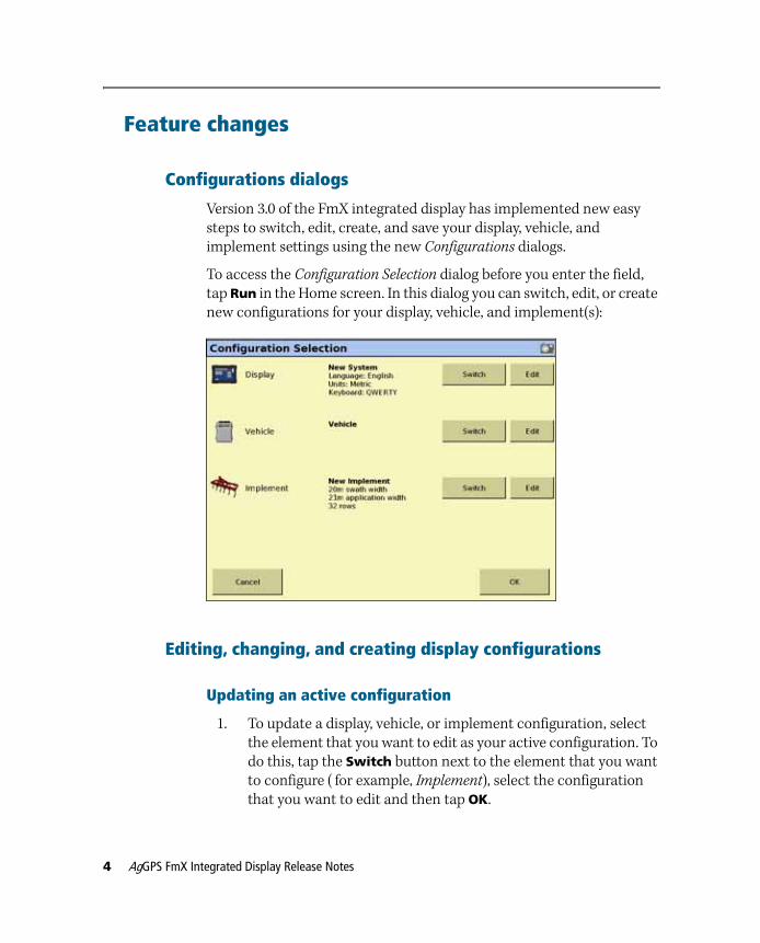
Version 3.0 of the FmX integrated display has implemented new easy steps to switch, edit, create, and save your display, vehicle, and implement settings using the new Configurations dialogs.
To access the Configuration Selection dialog before you enter the field, tap Run in the Home screen. In this dialog you can switch, edit, or create new configurations for your display, vehicle, and implement(s):
Editing, changing, and creating display configurations
Updating an active configuration
1. To update a display, vehicle, or implement configuration, select the element that you want to edit as your active configuration. To do this, tap the Switch button next to the element that you want to configure ( for example, Implement), select the configuration that you want to edit and then tap OK.
4 AgGPS FmX Integrated Display Release Notes
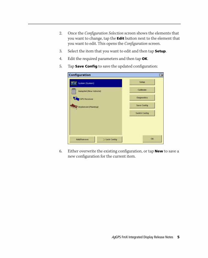
2. Once the Configuration Selection screen shows the elements that you want to change, tap the Edit button next to the element that you want to edit. This opens the Configuration screen.
3. Select the item that you want to edit and then tap Setup.
4. Edit the required parameters and then tap OK.
5. Tap Save Config to save the updated configuration:
6. Either overwrite the existing configuration, or tap New to save a new configuration for the current item.
AgGPS FmX Integrated Display Release Notes 5
Switching an active configuration
To switch from an active display, vehicle, or implement configuration to another element:
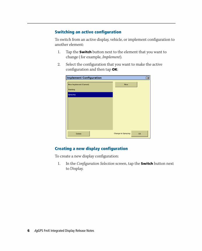
1. Tap the Switch button next to the element that you want to change ( for example, Implement).
2. Select the configuration that you want to make the active configuration and then tap OK:
Creating a new display configuration
To create a new display configuration:
1. In the Configuration Selection screen, tap the Switch button next to Display.
6 AgGPS FmX Integrated Display Release Notes
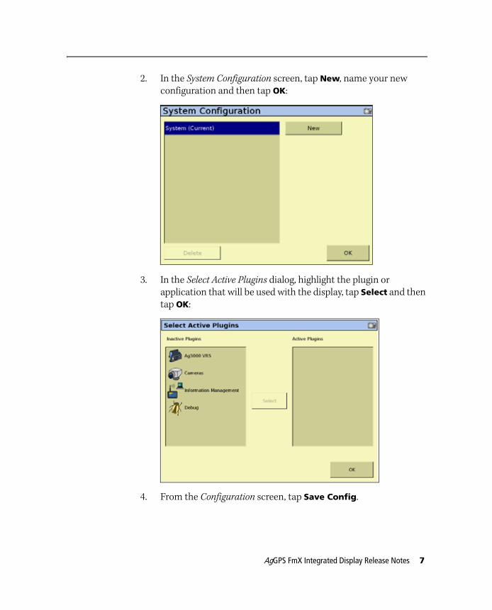
2. In the System Configuration screen, tap New, name your new configuration and then tap OK:
3. In the Select Active Plugins dialog, highlight the plugin or application that will be used with the display, tap Select and then tap OK:
4. From the Configuration screen, tap Save Config.
AgGPS FmX Integrated Display Release Notes 7
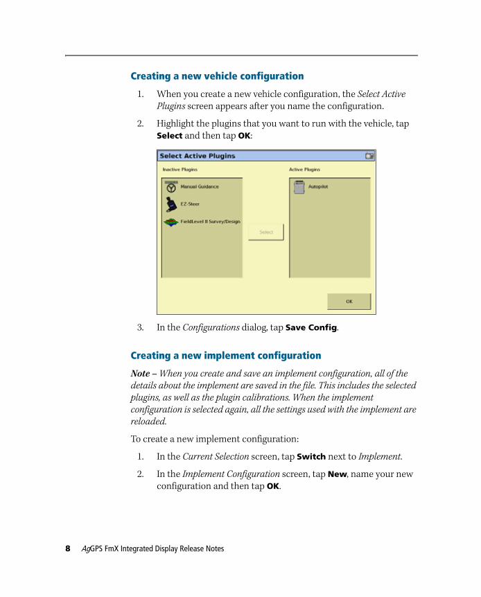
Creating a new vehicle configuration
1. When you create a new vehicle configuration, the Select Active
Plugins screen appears after you name the configuration.
2. Highlight the plugins that you want to run with the vehicle, tap Select and then tap OK:
3. In the Configurations dialog, tap Save Config.
Creating a new implement configuration
Note – When you create and save an implement configuration, all of the
details about the implement are saved in the file. This includes the selected
plugins, as well as the plugin calibrations. When the implement
configuration is selected again, all the settings used with the implement are
reloaded.
To create a new implement configuration:
1. In the Current Selection screen, tap Switch next to Implement.
2. In the Implement Configuration screen, tap New, name your new configuration and then tap OK.
8 AgGPS FmX Integrated Display Release Notes
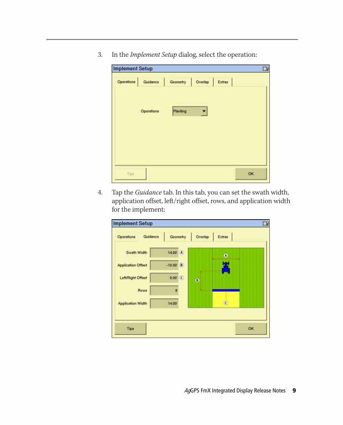
3. In the Implement Setup dialog, select the operation:
4. Tap the Guidance tab. In this tab, you can set the swath width, application offset, left/right offset, rows, and application width for the implement:
AgGPS FmX Integrated Display Release Notes 9
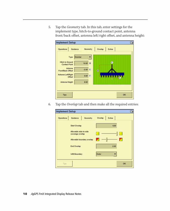
5. Tap the Geometry tab. In this tab, enter settings for the implement type, hitch-to-ground contact point, antenna front/back offset, antenna left/right offset, and antenna height:
6. Tap the Overlap tab and then make all the required entries:
10 AgGPS FmX Integrated Display Release Notes

7. Tap the Extras tab and then make the required entries:
8. Once you complete all entries, tap OK
9. In the Select Active Plugins screen, select the plugin or application that you want to use, tap Select and then tap OK:
10. From the Configurations screen, tap Save Config.
AgGPS FmX Integrated Display Release Notes 11
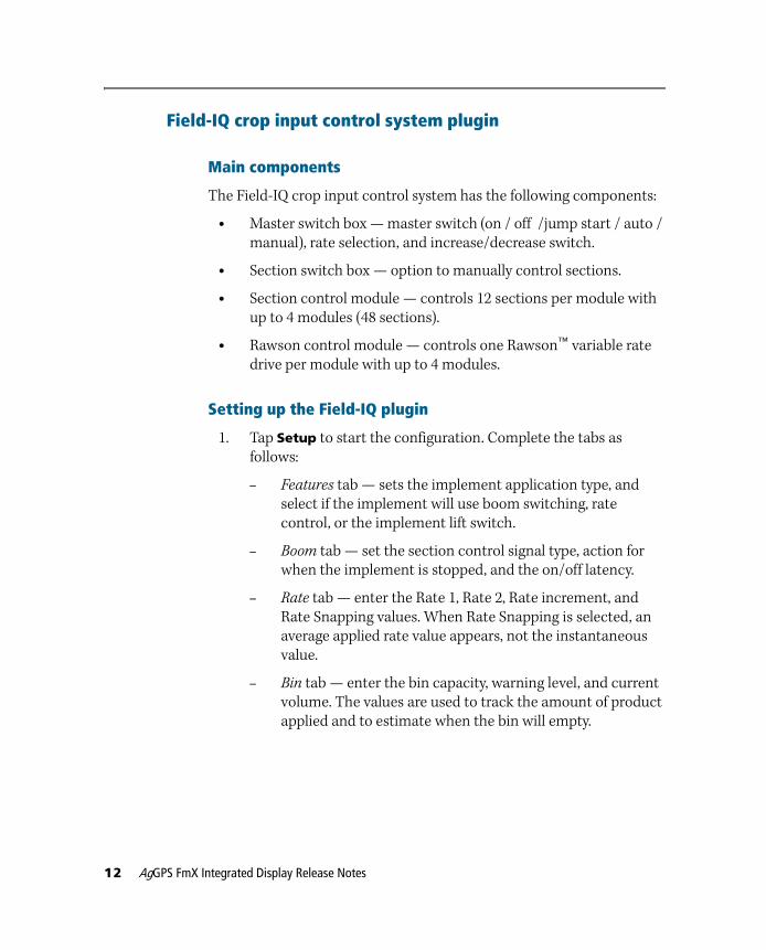
Field-IQ crop input control system plugin
Main components
The Field-IQ crop input control system has the following components:
• Master switch box — master switch (on / off /jump start / auto / manual), rate selection, and increase/decrease switch.
• Section switch box — option to manually control sections.
• Section control module — controls 12 sections per module with up to 4 modules (48 sections).
• Rawson control module — controls one Rawson™ variable rate drive per module with up to 4 modules.
Setting up the Field-IQ plugin
1. Tap Setup to start the configuration. Complete the tabs as follows:
– Features tab — sets the implement application type, and select if the implement will use boom switching, rate control, or the implement lift switch.
– Boom tab — set the section control signal type, action for when the implement is stopped, and the on/off latency.
– Rate tab — enter the Rate 1, Rate 2, Rate increment, and Rate Snapping values. When Rate Snapping is selected, an average applied rate value appears, not the instantaneous value.
– Bin tab — enter the bin capacity, warning level, and current volume. The values are used to track the amount of product applied and to estimate when the bin will empty.
12 AgGPS FmX Integrated Display Release Notes
– Hardware tab — shows the serial number and relative location on the implement of the connected Rate and Section Control modules. If the Rate Control Module is connected, you must set the application width for each module; if the Section Control Module is connected, you must set the number of rows that each module controls.
– Sections tab — enter the number or rows per section that are controlled.
– Override tab — enter the jump start speed if GPS signal is lost so that you can continue operating at a constant speed until the GPS signal is reacquired. The Minimum Override
Speed sets the minimum speed that the Rate Control applies, regardless of the actual ground speed.
AgGPS FmX Integrated Display Release Notes 13
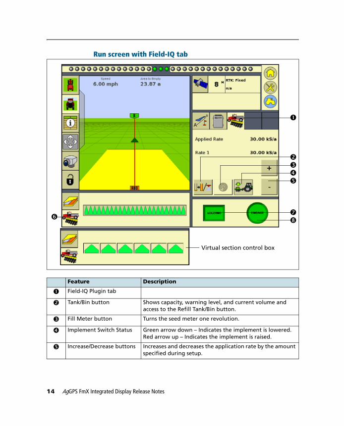
Run screen with Field-IQ tab
Feature Description
c Field-IQ Plugin tab
d Tank/Bin button Shows capacity, warning level, and current volume and access to the Refill Tank/Bin button.
e Fill Meter button Turns the seed meter one revolution.
f Implement Switch Status Green arrow down – Indicates the implement is lowered. Red arrow up – Indicates the implement is raised.
g Increase/Decrease buttons Increases and decreases the application rate by the amount specified during setup.
Virtual section control box
c
defg
ij
h
14 AgGPS FmX Integrated Display Release Notes
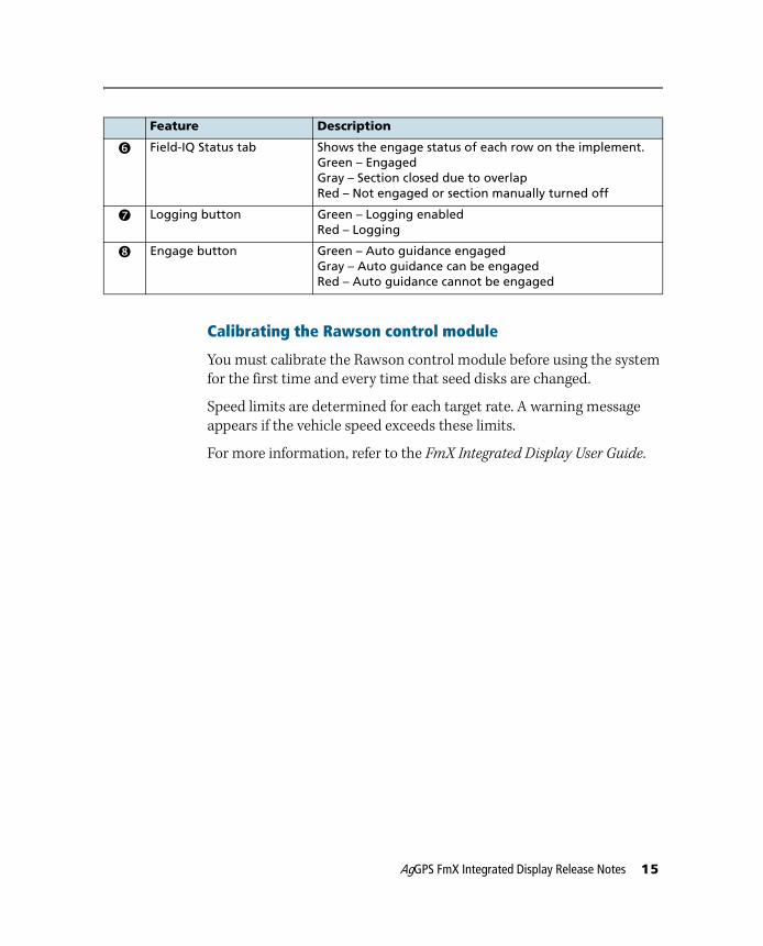
Calibrating the Rawson control module
You must calibrate the Rawson control module before using the system for the first time and every time that seed disks are changed.
Speed limits are determined for each target rate. A warning message appears if the vehicle speed exceeds these limits.
For more information, refer to the FmX Integrated Display User Guide.
h Field-IQ Status tab Shows the engage status of each row on the implement.Green – EngagedGray – Section closed due to overlapRed – Not engaged or section manually turned off
i Logging button Green – Logging enabledRed – Logging
j Engage button Green – Auto guidance engagedGray – Auto guidance can be engagedRed – Auto guidance cannot be engaged
Feature Description
AgGPS FmX Integrated Display Release Notes 15
Yield monitoring plugin
Version 3.0 of the FmX integrated display is compatible with yield monitoring data from the John Deere 60 and 70 series combines, and the AgLeader YM2000.
Before connecting the cable from John Deere diagnostic port to the FmX integrated display, make sure that the display hardware is revision N or later.
Configuring the John Deere Yield Monitor
1. Install the Yield Monitoring plugin.
2. From the Configuration screen, select the Yield Monitoring plugin and then tap Setup. The Yield Monitoring Settings screen appears.
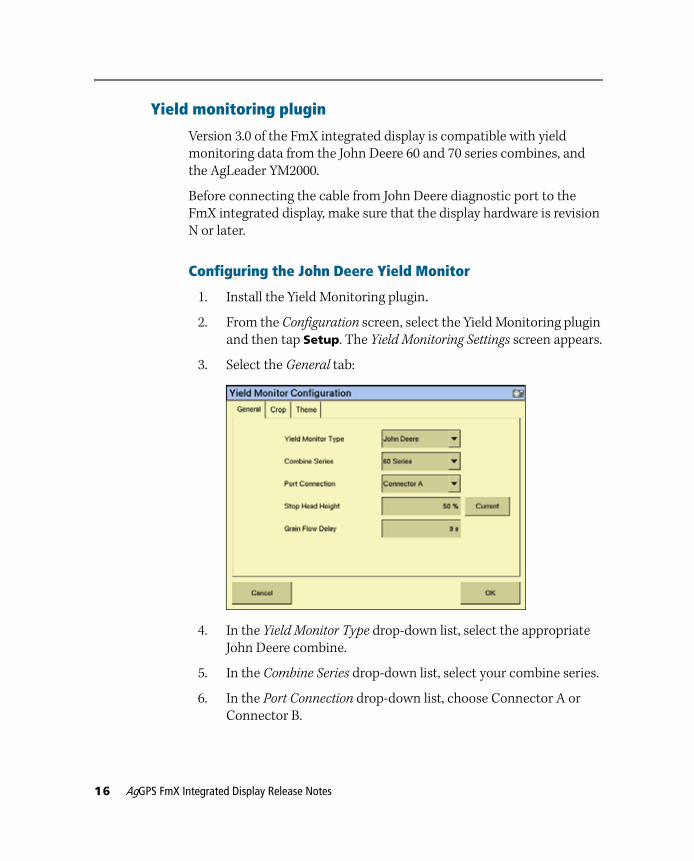
3. Select the General tab:
4. In the Yield Monitor Type drop-down list, select the appropriate John Deere combine.
5. In the Combine Series drop-down list, select your combine series.
6. In the Port Connection drop-down list, choose Connector A or Connector B.
16 AgGPS FmX Integrated Display Release Notes
7. Select the Stop Head Height field and then enter a height (this must be lower than the combines header height).
8. In the Grain Flow Delay field, enter the time in seconds that it takes the grain to travel from the head to the clean grain tank.
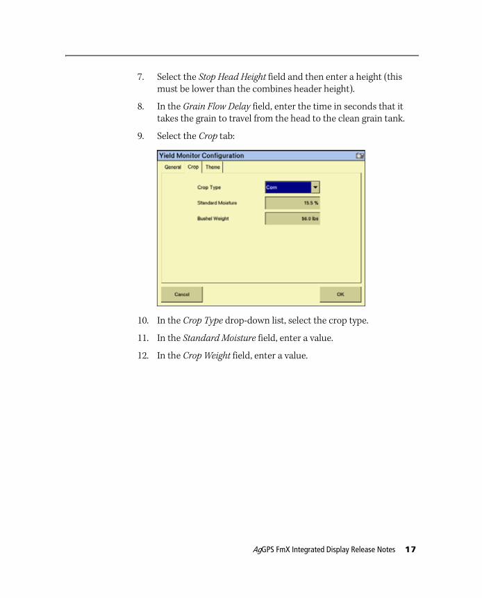
9. Select the Crop tab:
10. In the Crop Type drop-down list, select the crop type.
11. In the Standard Moisture field, enter a value.
12. In the Crop Weight field, enter a value.
AgGPS FmX Integrated Display Release Notes 17
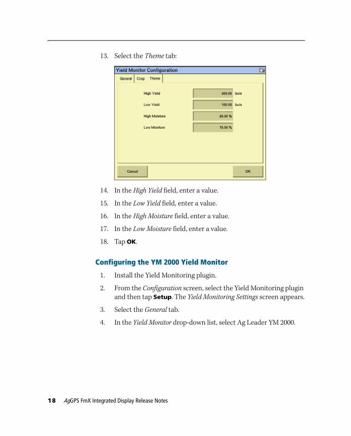
13. Select the Theme tab:
14. In the High Yield field, enter a value.
15. In the Low Yield field, enter a value.
16. In the High Moisture field, enter a value.
17. In the Low Moisture field, enter a value.
18. Tap OK.
Configuring the YM 2000 Yield Monitor
1. Install the Yield Monitoring plugin.
2. From the Configuration screen, select the Yield Monitoring plugin and then tap Setup. The Yield Monitoring Settings screen appears.
3. Select the General tab.
4. In the Yield Monitor drop-down list, select Ag Leader YM 2000.
18 AgGPS FmX Integrated Display Release Notes
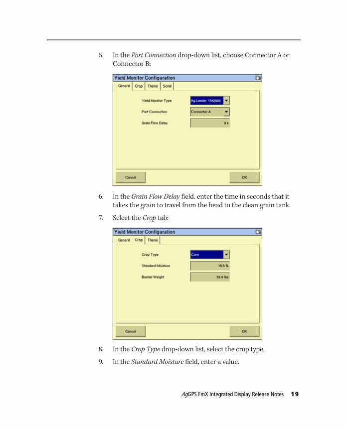
5. In the Port Connection drop-down list, choose Connector A or Connector B:
6. In the Grain Flow Delay field, enter the time in seconds that it takes the grain to travel from the head to the clean grain tank.
7. Select the Crop tab:
8. In the Crop Type drop-down list, select the crop type.
9. In the Standard Moisture field, enter a value.
AgGPS FmX Integrated Display Release Notes 19
10. In the Crop Weight field, enter a value.
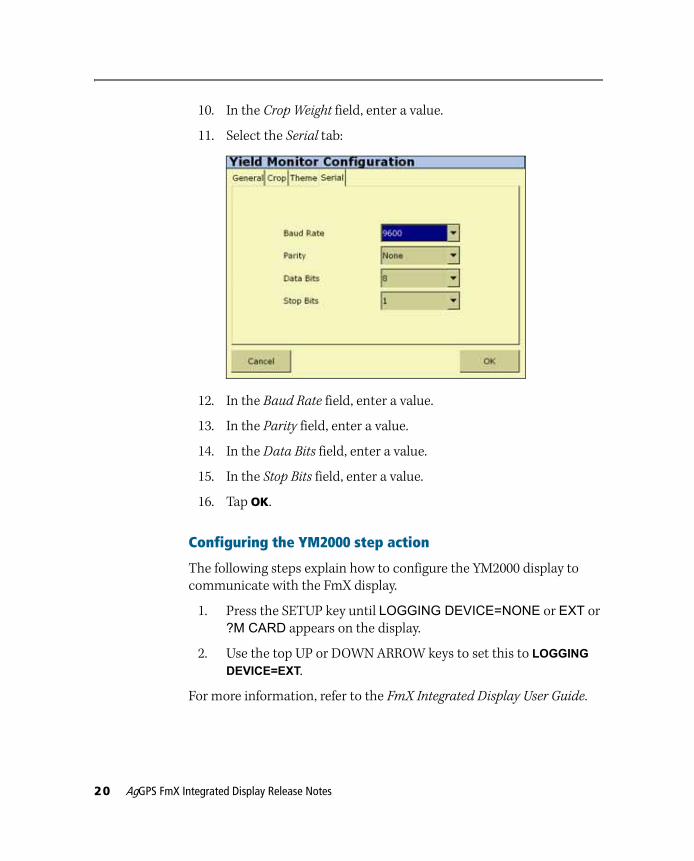
11. Select the Serial tab:
12. In the Baud Rate field, enter a value.
13. In the Parity field, enter a value.
14. In the Data Bits field, enter a value.
15. In the Stop Bits field, enter a value.
16. Tap OK.
Configuring the YM2000 step action
The following steps explain how to configure the YM2000 display to communicate with the FmX display.
1. Press the SETUP key until LOGGING DEVICE=NONE or EXT or ?M CARD appears on the display.
2. Use the top UP or DOWN ARROW keys to set this to LOGGING
DEVICE=EXT.
For more information, refer to the FmX Integrated Display User Guide.
20 AgGPS FmX Integrated Display Release Notes
Operating Yield Monitoring
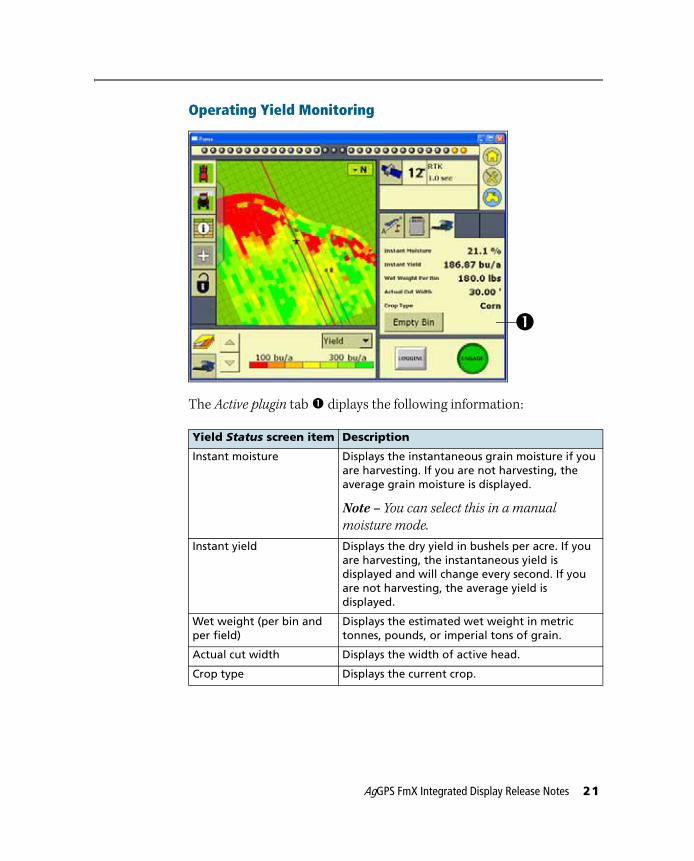
The Active plugin tab c diplays the following information:
Yield Status screen item Description
Instant moisture Displays the instantaneous grain moisture if you are harvesting. If you are not harvesting, the average grain moisture is displayed.
Note – You can select this in a manual
moisture mode.
Instant yield Displays the dry yield in bushels per acre. If you are harvesting, the instantaneous yield is displayed and will change every second. If you are not harvesting, the average yield is displayed.
Wet weight (per bin and per field)
Displays the estimated wet weight in metric tonnes, pounds, or imperial tons of grain.
Actual cut width Displays the width of active head.
Crop type Displays the current crop.
c
AgGPS FmX Integrated Display Release Notes 21
GreenSeeker variable rate application plugin
Version 3.0 of the FmX integrated display now supports the GreenSeeker variable rate application system. Together, the two systems can apply Nitrogen in the correct amounts, where it is required, in real time, based on the feedback from the optical sensors.
Main components
Operating the GreenSeeker system
The GreenSeeker system requires the one of the following applications to be active on the FmX integrated display:
• The AgGPS EZ-Boom® automated application control system
• The Tru Application Control™ system
• The Field-IQ crop input control system
• The Serial Rate Control system
Calibrate the GreenSeeker system through the Run screen on the FmX integrated display. Before calibration, you must collect or input reference strip data to the FmX integrated display; do this with either the boom mounted sensors on the RT200, or with the GreenSeeker hand held sensor prior to application.
If you use the RT200 interface module for variable rate control, you must set up the application equipment and rate controller to match the expected delivery rate commands.
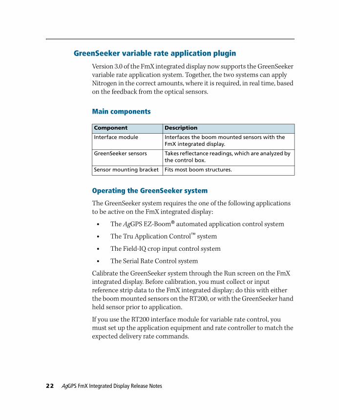
Component Description
Interface module Interfaces the boom mounted sensors with the FmX integrated display.
GreenSeeker sensors Takes reflectance readings, which are analyzed by the control box.
Sensor mounting bracket Fits most boom structures.
22 AgGPS FmX Integrated Display Release Notes
Preparing the GreenSeeker plugin
To configure variable rate application on the FmX integrated display, do the following:
1. Power up the RT200 interface module and the rate controller (if required).
The RT200 interface module’s green Power LED will blink three times accompanied by three beeps when the unit is first turned on. Following this, the Status LED will blink in time with each transmission of sensor data over the CAN bus. Expect to see a brief green flash, followed by a red flash at the I/M message rate (typically at 0.5sec) - this indicates that data from the left (green flash) and right (red flash) CAN ports is being transmitted.
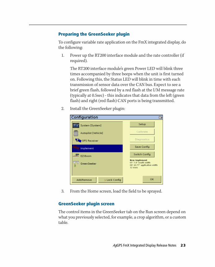
2. Install the GreenSeeker plugin:
3. From the Home screen, load the field to be sprayed.
GreenSeeker plugin screen
The control items in the GreenSeeker tab on the Run screen depend on what you previously selected, for example, a crop algorithm, or a custom table.
AgGPS FmX Integrated Display Release Notes 23
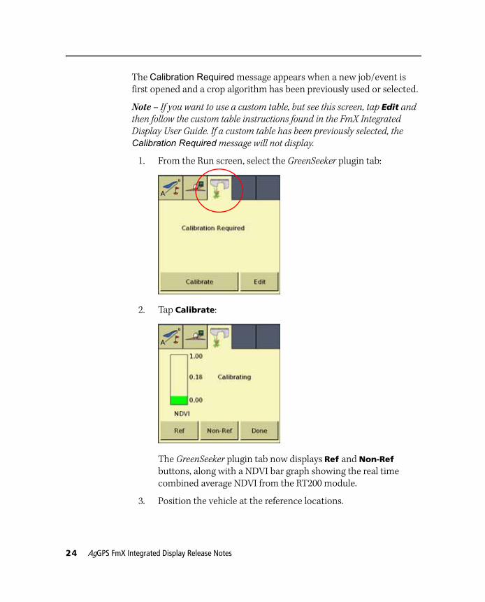
The Calibration Required message appears when a new job/event is first opened and a crop algorithm has been previously used or selected.
Note – If you want to use a custom table, but see this screen, tap Edit and
then follow the custom table instructions found in the FmX Integrated
Display User Guide. If a custom table has been previously selected, the
Calibration Required message will not display.
1. From the Run screen, select the GreenSeeker plugin tab:
2. Tap Calibrate:
The GreenSeeker plugin tab now displays Ref and Non-Ref buttons, along with a NDVI bar graph showing the real time combined average NDVI from the RT200 module.
3. Position the vehicle at the reference locations.
24 AgGPS FmX Integrated Display Release Notes
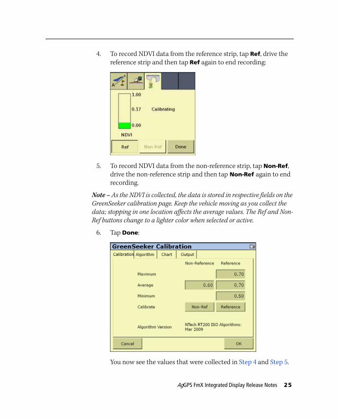
4. To record NDVI data from the reference strip, tap Ref, drive the reference strip and then tap Ref again to end recording:
5. To record NDVI data from the non-reference strip, tap Non-Ref, drive the non-reference strip and then tap Non-Ref again to end recording.
Note – As the NDVI is collected, the data is stored in respective fields on the
GreenSeeker calibration page. Keep the vehicle moving as you collect the
data; stopping in one location affects the average values. The Ref and Non-
Ref buttons change to a lighter color when selected or active.
6. Tap Done:
You now see the values that were collected in Step 4 and Step 5.
AgGPS FmX Integrated Display Release Notes 25
To collect fresh data from this screen, tap the Non-Ref or Reference buttons. You will not see the new values until you deselect the respective button.
To manually override or input data, select the various fields and then use the screen keypad.
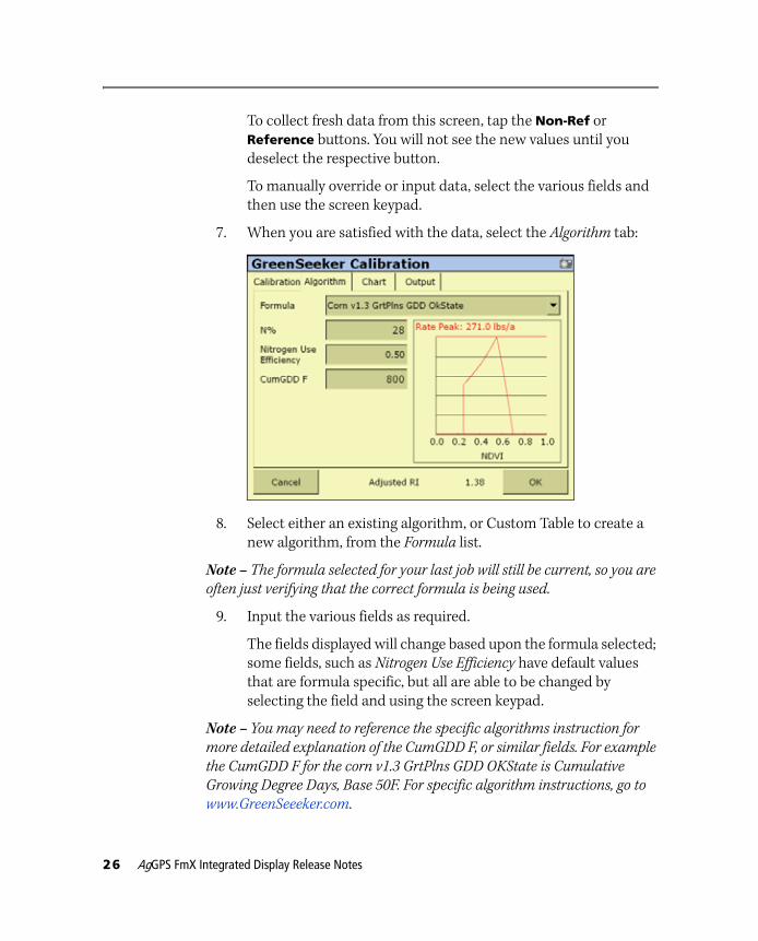
7. When you are satisfied with the data, select the Algorithm tab:
8. Select either an existing algorithm, or Custom Table to create a new algorithm, from the Formula list.
Note – The formula selected for your last job will still be current, so you are
often just verifying that the correct formula is being used.
9. Input the various fields as required.
The fields displayed will change based upon the formula selected; some fields, such as Nitrogen Use Efficiency have default values that are formula specific, but all are able to be changed by selecting the field and using the screen keypad.
Note – You may need to reference the specific algorithms instruction for
more detailed explanation of the CumGDD F, or similar fields. For example
the CumGDD F for the corn v1.3 GrtPlns GDD OKState is Cumulative
Growing Degree Days, Base 50F. For specific algorithm instructions, go to
www.GreenSeeeker.com.
26 AgGPS FmX Integrated Display Release Notes
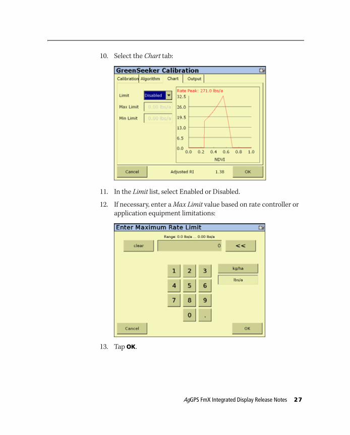
10. Select the Chart tab:
11. In the Limit list, select Enabled or Disabled.
12. If necessary, enter a Max Limit value based on rate controller or application equipment limitations:
13. Tap OK.
AgGPS FmX Integrated Display Release Notes 27
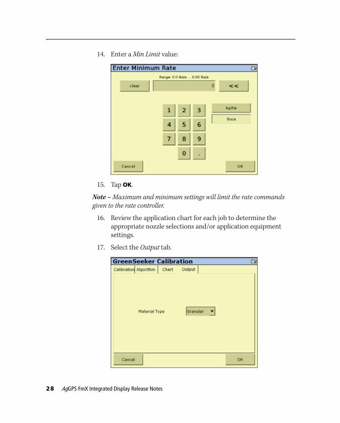
14. Enter a Min Limit value:
15. Tap OK.
Note – Maximum and minimum settings will limit the rate commands
given to the rate controller.
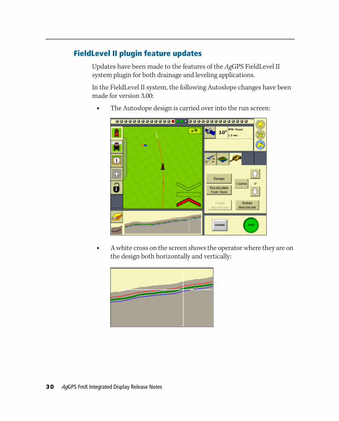
16. Review the application chart for each job to determine the appropriate nozzle selections and/or application equipment settings.
17. Select the Output tab.
28 AgGPS FmX Integrated Display Release Notes

18. In the Material Type list, select either Granular, or Liquid.
19. Tap OK.
AgGPS FmX Integrated Display Release Notes 29
FieldLevel II plugin feature updates
Updates have been made to the features of the AgGPS FieldLevel II system plugin for both drainage and leveling applications.
In the FieldLevel II system, the following Autoslope changes have been made for version 3.00:
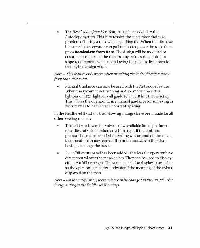
• The Autoslope design is carried over into the run screen:
• A white cross on the screen shows the operator where they are on the design both horizontally and vertically:
30 AgGPS FmX Integrated Display Release Notes
• The Recalculate from Here feature has been added to the Autoslope system. This is to resolve the subsurface drainage problem of hitting a rock when installing tile. When the tile plow hits a rock, the operator can pull the boot up over the rock, then press Recalculate from Here. The design will be modified to ensure that the rest of the tile run stays within the minimum slope requirement, while not allowing the pipe to dive down to the original design grade.
Note – This feature only works when installing tile in the direction away
from the outlet point.
• Manual Guidance can now be used with the Autoslope feature. When the system is not running in Auto mode, the virtual lightbar or LB25 lightbar will guide to any AB line that is set up. This allows the operator to use manual guidance for surveying in section lines to be tiled at a constant spacing.
In the FieldLevel II system, the following changes have been made for all other leveling models:
• The ability to invert the valve is now available for all platforms regardless of valve module or vehicle type. If the tank and pressure hoses are installed the wrong way around on the valve, the operator can now correct this in the software rather than having to change the hoses.
• A cut/fill status panel has been added. This lets the operator have direct control over the map’s colors. They can be used to display either cut/fill or height. The status panel also displays a scale bar so the operator can better understand the meaning of the colors displayed on the map.
Note – For the cut/fill map, these colors can be changed in the Cut/fill Color
Range setting in the FieldLevel II settings.
AgGPS FmX Integrated Display Release Notes 31
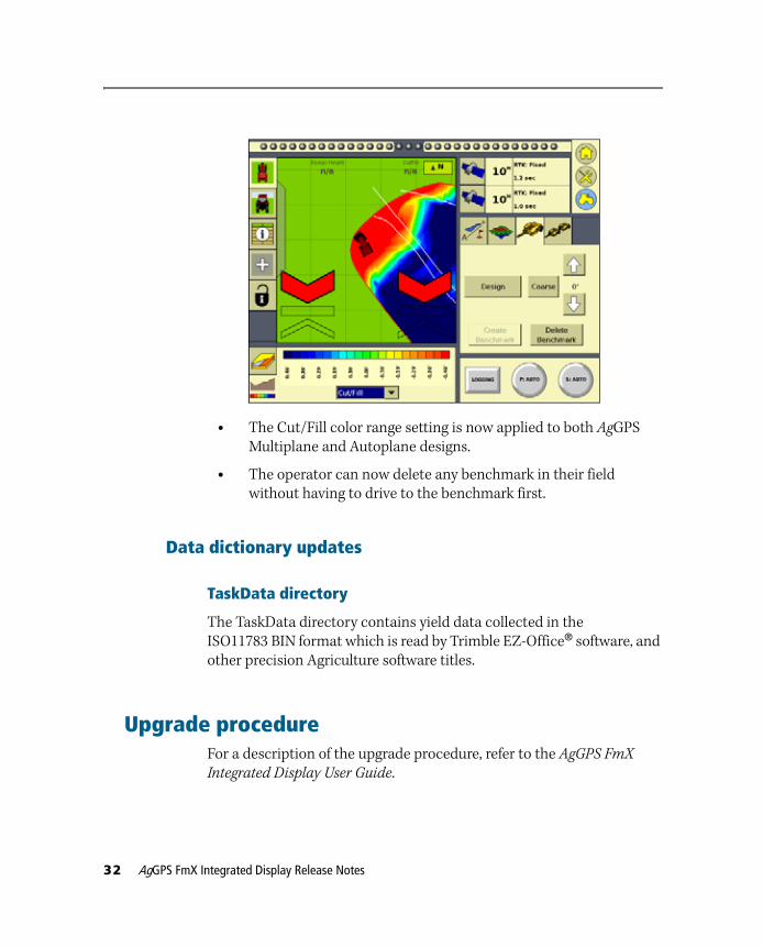
• The Cut/Fill color range setting is now applied to both AgGPS Multiplane and Autoplane designs.
• The operator can now delete any benchmark in their field without having to drive to the benchmark first.
Data dictionary updates
TaskData directory
The TaskData directory contains yield data collected in the ISO11783 BIN format which is read by Trimble EZ-Office® software, and other precision Agriculture software titles.
Upgrade procedureFor a description of the upgrade procedure, refer to the AgGPS FmX
Integrated Display User Guide.
32 AgGPS FmX Integrated Display Release Notes