Embed Size (px)
Citation preview
Grant Agreement No. 619572
COSIGN
Combining Optics and SDN In next Generation data centre Networks Programme: Information and Communication Technologies Funding scheme: Collaborative Project – Large-Scale Integrating Project
Deliverable D2.7
Final Report on Fibre Development
Due date of deliverable: December 31st, 2016 Actual submission date: December 19th, 2016
Start date of project: January 1, 2014 Duration: 39 months Lead contractor for this deliverable: University of Southampton Other contributors: OFS
Project co-funded by the European Commission within the Seventh Framework Programme Dissemination Level
PU Public X PP Restricted to other programme participants (including the Commission Services) RE Restricted to a group specified by the consortium (including the Commission Services) CO Confidential, only for members of the consortium (including the Commission Services)
COSIGN
Ref. Ares(2017)2620700 - 23/05/2017

619572 - ICT COSIGN Deliverable D2.7 Combining Optics and SDN In next Generation data centre Networks
Page 2 of 22
Executive Summary In this deliverable, we provide a summary of the various fibres delivered to the project by UNISOUTH and OFS. These include Multi-Core Fibres (MCF), Multi-Element Fibres (MEF), and Few-Mode Fibres (FMF) for spatial division multiplexed (SDM) transmission, as well as Hollow Core Photonic Bandgap Fibres (HC-PBGF) for low-latency transmission. All delivered fibre types have been successfully integrated in data-centre demonstrator experiments by project partners (with the exception of the FMF). Additionally, we describe the designs for both a 3-mode and single-mode 52-core MCF currently under fabrication, aiming at a high data-capacity demonstration with record-high spatial channel count within the time-frame of the COSIGN project.
Furthermore, we report in detail on the performance of the packaged multi-lane switch prototype with integrated 4-core MCFs, which has been developed as a joint effort between UNISOUTH and POLATIS. Connection losses down to less than 2.2 dB are obtained for the multilane switch prototype. The working distance within the switch potentially allows for the integration of up to 96 4-core MCF ports, although this will require an improved precision in the alignment of the switch components. Furthermore, a 2x2 switch setup including a 1-km transmission length and fan-out devices on all 4-core MCFs has been prepared for inclusion in a long-term system demonstrator.
Legal Notice
The information in this document is subject to change without notice.
The Members of the COSIGN Consortium make no warranty of any kind with regard to this document, including, but not limited to, the implied warranties of merchantability and fitness for a particular purpose. The Members of the COSIGN Consortium shall not be held liable for errors contained herein or direct, indirect, special, incidental or consequential damages in connection with the furnishing, performance, or use of this material.
Possible inaccuracies of information are under the responsibility of the project. This report reflects solely the views of its authors. The European Commission is not liable for any use that may be made of the information contained therein.

619572 - ICT COSIGN Deliverable D2.7 Combining Optics and SDN In next Generation data centre Networks
Page 3 of 22
Document Information
Status and Version: Version 07 Date of Issue: December 19th, 2016 Dissemination level: PU Author(s): Name Partner Hans Christian Mulvad UNISOUTH J. R. Hayes UNISOUTH M. Petrovich UNISOUTH D.J. Richardson UNISOUTH Yongmin Jung UNISOUTH L. Grüner-Nielsen OFS R. V. Jensen OFS Reviewed by L. Grüner-Nielsen OFS Yaniv Ben-Itzhak IBM Nick Parsons (section 4) POLATIS Edited by: Hans Christian Mulvad UNISOUTH Checked by : Sarah Ruepp DTU
619572 - ICT COSIGN Deliverable D2.7 Combining Optics and SDN In next Generation data centre Networks
Page 4 of 22
Table of Contents 1 Introduction ..................................................................................................................................... 5
1.1 Fibre Fabrication ........................................................................................................................ 5
1.2 Multilane Switching ................................................................................................................... 5
1.3 Reference Material ..................................................................................................................... 6 1.3.1 Reference Documents ....................................................................................................... 6 1.3.2 Acronyms and Abbreviations ........................................................................................... 6
1.4 Document History ...................................................................................................................... 7
2 Overview of Fibres delivered to the Project ................................................................................. 8
2.1 4-Core Multicore Fibres for Multilane Switching ...................................................................... 8 2.1.1 1st Generation Multicore Fibres ........................................................................................ 8 2.1.2 2nd Generation Multicore Fibres ....................................................................................... 9
2.2 Multi-Element Fibres .................................................................................................................. 9
2.3 7-core Multicore Fibre ................................................................................................................ 9
2.4 Few-Mode Fibres ...................................................................................................................... 10
2.5 Hollow Core Photonic Bandgap Fibres for Low-Latency Transmission ................................. 11 2.5.1 1st Generation Hollow Core Photonic Bandgap Fibres ................................................... 11 2.5.2 2nd Generation Hollow Core Photonic Bandgap Fibres .................................................. 12
3 Fabrication Plans for Multicore Fibre with 52 Cores ............................................................... 13
4 Multilane Switch ........................................................................................................................... 15
4.1 Operation Principle and Technical Information ....................................................................... 15
4.2 Free-Space Characterisations before Packaging ....................................................................... 16
4.3 Characterisations of the Packaged Multilane Switch ............................................................... 18
4.4 Multilane Switch Setup for the Long Term Demonstrator ....................................................... 20
5 Summary ....................................................................................................................................... 22
619572 - ICT COSIGN Deliverable D2.7 Combining Optics and SDN In next Generation data centre Networks
Page 5 of 22
1 Introduction
1.1 Fibre Fabrication With the aim of demonstrating the potential of novel optical fibre types for data centre interconnections, several fibres have been fabricated and delivered by UNISOUTH and OFS to project partners within the COSIGN project. In the first part of this report, the fibres delivered to the project and their use in partner experiments are summarised. Firstly, various Spatial Division Multiplexing (SDM) fibres (which in principle allow increased transmission capacity through several spatial channels in a single fibre) have been delivered, including Multi-Core Fibres (MCF), Multi-Element Fibres (MEF) and Few-Mode Fibres (FMF). From OFS, both 7-core MCFs and FMF have been delivered to DTU for experiments. At UNISOUTH, 4-core MCFs suitable for integration within the POLATIS fibre beam-steering switch have been developed, including low-cross talk samples based on OFS core preforms. Furthermore, MEFs samples have been delivered to UNIVBRIS for data centre demonstrators. Hollow Core Photonic Bandgap Fibres (HC-PBGFs) for low latency transmission have been delivered to UNIVBRIS and also improved throughout the project. Additionally, we describe two 52-core MCF designs based on core preforms from OFS, one with 2-mode group cores and one with single-mode cores. These MCFs are currently under fabrication and would represent a record-high spatial channel count in a single SDM fibre. Project partners have expressed strong interest in employing the 52-core MCFs, aiming at high data-capacity demonstrations within the extended time-frame of the COSIGN project.
1.2 Multilane Switching During the course of the COSIGN project, it was decided to investigate, within WP2, the integration of SDM fibre types such as multicore fibre (MCF) with the Polatis switch. A key aim of the COSIGN project is to enable software-defined dynamic reconfiguration at the physical (fibre) layer. As previously explained in D2.9, the integration of SDM fibres with an optical circuit switch technology such as the POLATIS switch offers the prospect of routing multilane traffic on a single fibre pair, thereby substantially reducing the cost and control complexity of such dynamically reconfigurable links. Hence, POLATIS and UNISOUTH decided to collaborate on the development of a multilane switch with integrated MCF fibres. This work included several stages: the development of a 4-core MCF suitable for integration within the switch (cf. D2.3 and D2.5), a theoretical and numerical analysis of a telecentric alignment of the switch optics to enable low-loss MCF-to-MCF switching performance followed by initial experimental tests of the configuration (cf. D2.9), and finally the connectorisation of the MCFs with collimators followed by their integration within the switch assembly (described in this document). In this deliverable, we report in detail on the performance of the packaged multi-lane switch prototype with integrated 4-core MCFs. Connection losses down to less than 2.2 dB are achieved. The switch employs a working distance that would enable the integration of up to 96 4-core MCF ports, although the precision in the lateral alignment of the switch components will need to be better controlled to realise this in practice. Furthermore, a 2x2 switch setup including a 1-km transmission fibre and fan-in/out devices on all MCFs has been prepared for the long-term demonstrator planned within the project.

619572 - ICT COSIGN Deliverable D2.7 Combining Optics and SDN In next Generation data centre Networks
Page 6 of 22
1.3 Reference Material
1.3.1 Reference Documents
[1] COSIGN FP7 Collaborative Project Grant Agreement Annex I - "Description of Work" [2] M7 - Definition of Multi-core fibres (MCF) specifications [3] M8 - Specification of target Hollow Core Photonic Bandgap Fibre (PBGF) Properties [4] M10 - Delivery of first generation ultralow latency fibres and multi-core fibres (MCF) [5] M11 - Delivery of First Generation Multi-Core Fibres for Multi-Lane Switching [6] M12 - Delivery of Second Generation Low Latency Fibres and Multi-Core Fibres for
Multilane Switching [7] D2.3 - Report on development of first generation Multi-Core Fibres and Photonic Bandgap
Fibres [8] D2.5 - Report on Development of Optimised Second Generation Fibres [9] D2.9 - Report on performance of MCF designed for multi-lane switching experiments
[10] Shuangyi Yan, Emilio Hugues-Salas, Victor J. F. Rancaňo, Yi Shu, George M. Saridis, Bijan Rahimzadeh Rofoee, Yan Yan, Adaranijo Peters, Saurabh Jain, Timothy May-Smith, Periklis Petropoulos, David J. Richardson, Georgios Zervas, and Dimitra Simeonidou, "Archon: A Function Programmable Optical Interconnect Architecture for Transparent Intra and Inter Data Center SDM/TDM/WDM Networking," J. Lightwave Technol. 33, 1586-1595 (2015)
[11] Valerija Kamchevska, Ashenafi Kiros Medhin, Francesco Da Ros, Feihong Ye, Rameez Asif, Anna Manolova Fagertun, Sarah Ruepp, Michael Berger, Lars Dittmann, Toshio Morioka, Leif Katsuo Oxenløwe, and Michael Galili, "Experimental Demonstration of Multidimensional Switching Nodes for All-Optical Data Center Networks," J. Lightwave Technol. 34, 1837-1843 (2016)
[12] G. M. Saridis et al., "EVROS: All-optical programmable disaggregated data centre interconnect utilizing hollow-core bandgap fibre," 2015 European Conference on Optical Communication (ECOC), Valencia, 2015, paper Tu.3.6.5
[13] Koji Igarashi, Daiki Soma, Yuta Wakayama, Koki Takeshima, Yu Kawaguchi, Noboru Yoshikane, Takehiro Tsuritani, Itsuro Morita, and Masatoshi Suzuki, "Ultra-dense spatial-division-multiplexed optical fiber transmission over 6-mode 19-core fibers," Opt. Express 24, 10213-10231 (2016)
[14] Hans Christian Hansen Mulvad, Andrew Parker, Bryan King, Daryl Smith, Mate Kovacs, Saurabh Jain, John Hayes, Marco Petrovich, David J. Richardson, Nick Parsons, “Beam-Steering All-Optical Switch for Multi-Core Fibers”, to be presented at OFC 2017, paper Tu2C.4
1.3.2 Acronyms and Abbreviations Most frequently used acronyms in the Deliverable are listed below. Additional acronyms may be defined and used throughout the text.
DoW Description of Work SDN Software Defined Networks SDM Spatial Division Multiplexing MCF Multi-Core Fibre FMF Few-Mode Fibre MEF Multi-Element Fibre HC-PBGF Hollow-Core Photonic Bandgap Fibre OTDR Optical Time-Domain Reflectometry MFD Mode Field Diameter XT Cross-talk

619572 - ICT COSIGN Deliverable D2.7 Combining Optics and SDN In next Generation data centre Networks
Page 7 of 22
1.4 Document History
Version Date Authors Comment 01 12th December 2016
See the list of authors
First draft (section 4 not ready) 02 14th December 2016 Second draft (section 4 ready) 03 14th December 2016 Including corrections by Y.
Jung (section 3) and N. Parsons (section 4)
04 15th December Reviewed by Yaniv (IBM) 05 16th December Reviewed by Lars (OFS) 06 16th December Included comments by all co-
authors, ready for quality check 07 19th December Final version
619572 - ICT COSIGN Deliverable D2.7 Combining Optics and SDN In next Generation data centre Networks
Page 8 of 22
2 Overview of Fibres delivered to the Project In the following, we provide an overview of the various fibres delivered to the project. For each fibre, the main properties and the application of the fibre in partner experiments are summarised. The detailed characteristics of the fibres were reported in previous deliverable and milestone documents, as cited below.
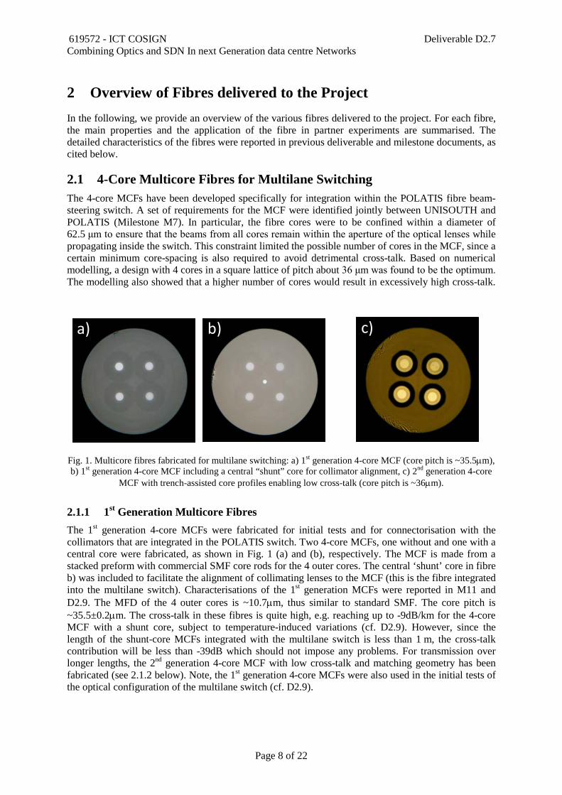
2.1 4-Core Multicore Fibres for Multilane Switching The 4-core MCFs have been developed specifically for integration within the POLATIS fibre beam-steering switch. A set of requirements for the MCF were identified jointly between UNISOUTH and POLATIS (Milestone M7). In particular, the fibre cores were to be confined within a diameter of 62.5 μm to ensure that the beams from all cores remain within the aperture of the optical lenses while propagating inside the switch. This constraint limited the possible number of cores in the MCF, since a certain minimum core-spacing is also required to avoid detrimental cross-talk. Based on numerical modelling, a design with 4 cores in a square lattice of pitch about 36 μm was found to be the optimum. The modelling also showed that a higher number of cores would result in excessively high cross-talk.
Fig. 1. Multicore fibres fabricated for multilane switching: a) 1st generation 4-core MCF (core pitch is ~35.5µm), b) 1st generation 4-core MCF including a central “shunt” core for collimator alignment, c) 2nd generation 4-core
MCF with trench-assisted core profiles enabling low cross-talk (core pitch is ~36µm).
2.1.1 1st Generation Multicore Fibres The 1st generation 4-core MCFs were fabricated for initial tests and for connectorisation with the collimators that are integrated in the POLATIS switch. Two 4-core MCFs, one without and one with a central core were fabricated, as shown in Fig. 1 (a) and (b), respectively. The MCF is made from a stacked preform with commercial SMF core rods for the 4 outer cores. The central ‘shunt’ core in fibre b) was included to facilitate the alignment of collimating lenses to the MCF (this is the fibre integrated into the multilane switch). Characterisations of the 1st generation MCFs were reported in M11 and D2.9. The MFD of the 4 outer cores is ~10.7µm, thus similar to standard SMF. The core pitch is ~35.5±0.2µm. The cross-talk in these fibres is quite high, e.g. reaching up to -9dB/km for the 4-core MCF with a shunt core, subject to temperature-induced variations (cf. D2.9). However, since the length of the shunt-core MCFs integrated with the multilane switch is less than 1 m, the cross-talk contribution will be less than -39dB which should not impose any problems. For transmission over longer lengths, the 2nd generation 4-core MCF with low cross-talk and matching geometry has been fabricated (see 2.1.2 below). Note, the 1st generation 4-core MCFs were also used in the initial tests of the optical configuration of the multilane switch (cf. D2.9).
a) b) c)
619572 - ICT COSIGN Deliverable D2.7 Combining Optics and SDN In next Generation data centre Networks
Page 9 of 22
2.1.2 2nd Generation Multicore Fibres The 2nd generation 4-core MCFs has the same geometry as the 1st generation MCF, but was fabricated using core preforms produced by project partner OFS. These had a trench-assisted index profile for improved cross-talk performance. A microscope image of the fibre cross section is shown in Fig. 1 c). The detailed characteristics of the fibre were reported in M12 and D2.5. The MFD is ~11µm and the core pitch is 36±0.2µm, thus providing a good match and low-loss splicing to the 1st generation MCFs. Most importantly, the cross-talk is -54dB/km which is an improvement by several orders of magnitude compared to the 1st generation MCFs, making this fibre suitable for transmission over several km. The propagation loss is in the range 0.6-0.7dB/km. The total length of usable fibre drawn was 10 km. The 2nd generation MCF has been included in the setup prepared for the long-term demonstrator experiment, cf. section 4.4.
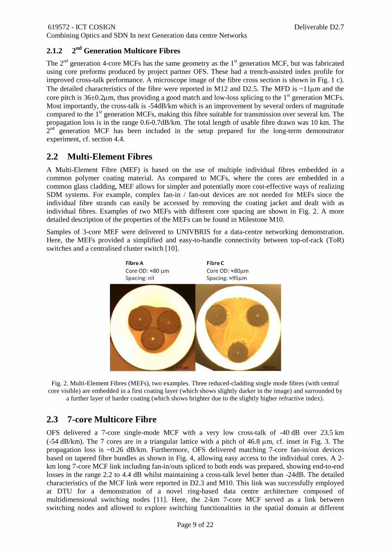
2.2 Multi-Element Fibres A Multi-Element Fibre (MEF) is based on the use of multiple individual fibres embedded in a common polymer coating material. As compared to MCFs, where the cores are embedded in a common glass cladding, MEF allows for simpler and potentially more cost-effective ways of realizing SDM systems. For example, complex fan-in / fan-out devices are not needed for MEFs since the individual fibre strands can easily be accessed by removing the coating jacket and dealt with as individual fibres. Examples of two MEFs with different core spacing are shown in Fig. 2. A more detailed description of the properties of the MEFs can be found in Milestone M10.
Samples of 3-core MEF were delivered to UNIVBRIS for a data-centre networking demonstration. Here, the MEFs provided a simplified and easy-to-handle connectivity between top-of-rack (ToR) switches and a centralised cluster switch [10].
Fig. 2. Multi-Element Fibres (MEFs), two examples. Three reduced-cladding single mode fibres (with central core visible) are embedded in a first coating layer (which shows slightly darker in the image) and surrounded by
a further layer of harder coating (which shows brighter due to the slightly higher refractive index).
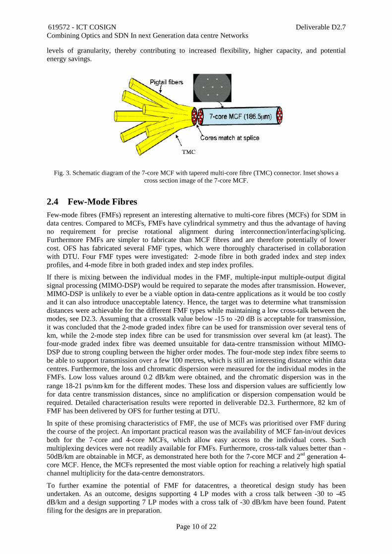
2.3 7-core Multicore Fibre OFS delivered a 7-core single-mode MCF with a very low cross-talk of -40 dB over 23.5 km (-54 dB/km). The 7 cores are in a triangular lattice with a pitch of 46.8 µm, cf. inset in Fig. 3. The propagation loss is ~0.26 dB/km. Furthermore, OFS delivered matching 7-core fan-in/out devices based on tapered fibre bundles as shown in Fig. 4, allowing easy access to the individual cores. A 2-km long 7-core MCF link including fan-in/outs spliced to both ends was prepared, showing end-to-end losses in the range 2.2 to 4.4 dB whilst maintaining a cross-talk level better than -24dB. The detailed characteristics of the MCF link were reported in D2.3 and M10. This link was successfully employed at DTU for a demonstration of a novel ring-based data centre architecture composed of multidimensional switching nodes [11]. Here, the 2-km 7-core MCF served as a link between switching nodes and allowed to explore switching functionalities in the spatial domain at different
619572 - ICT COSIGN Deliverable D2.7 Combining Optics and SDN In next Generation data centre Networks
Page 10 of 22
levels of granularity, thereby contributing to increased flexibility, higher capacity, and potential energy savings.
Fig. 3. Schematic diagram of the 7-core MCF with tapered multi-core fibre (TMC) connector. Inset shows a cross section image of the 7-core MCF.
2.4 Few-Mode Fibres Few-mode fibres (FMFs) represent an interesting alternative to multi-core fibres (MCFs) for SDM in data centres. Compared to MCFs, FMFs have cylindrical symmetry and thus the advantage of having no requirement for precise rotational alignment during interconnection/interfacing/splicing. Furthermore FMFs are simpler to fabricate than MCF fibres and are therefore potentially of lower cost. OFS has fabricated several FMF types, which were thoroughly characterised in collaboration with DTU. Four FMF types were investigated: 2-mode fibre in both graded index and step index profiles, and 4-mode fibre in both graded index and step index profiles.
If there is mixing between the individual modes in the FMF, multiple-input multiple-output digital signal processing (MIMO-DSP) would be required to separate the modes after transmission. However, MIMO-DSP is unlikely to ever be a viable option in data-centre applications as it would be too costly and it can also introduce unacceptable latency. Hence, the target was to determine what transmission distances were achievable for the different FMF types while maintaining a low cross-talk between the modes, see D2.3. Assuming that a crosstalk value below -15 to -20 dB is acceptable for transmission, it was concluded that the 2-mode graded index fibre can be used for transmission over several tens of km, while the 2-mode step index fibre can be used for transmission over several km (at least). The four-mode graded index fibre was deemed unsuitable for data-centre transmission without MIMO-DSP due to strong coupling between the higher order modes. The four-mode step index fibre seems to be able to support transmission over a few 100 metres, which is still an interesting distance within data centres. Furthermore, the loss and chromatic dispersion were measured for the individual modes in the FMFs. Low loss values around 0.2 dB/km were obtained, and the chromatic dispersion was in the range 18-21 ps/nm⋅km for the different modes. These loss and dispersion values are sufficiently low for data centre transmission distances, since no amplification or dispersion compensation would be required. Detailed characterisation results were reported in deliverable D2.3. Furthermore, 82 km of FMF has been delivered by OFS for further testing at DTU.
In spite of these promising characteristics of FMF, the use of MCFs was prioritised over FMF during the course of the project. An important practical reason was the availability of MCF fan-in/out devices both for the 7-core and 4-core MCFs, which allow easy access to the individual cores. Such multiplexing devices were not readily available for FMFs. Furthermore, cross-talk values better than -50dB/km are obtainable in MCF, as demonstrated here both for the 7-core MCF and 2nd generation 4-core MCF. Hence, the MCFs represented the most viable option for reaching a relatively high spatial channel multiplicity for the data-centre demonstrators.
To further examine the potential of FMF for datacentres, a theoretical design study has been undertaken. As an outcome, designs supporting 4 LP modes with a cross talk between -30 to -45 dB/km and a design supporting 7 LP modes with a cross talk of -30 dB/km have been found. Patent filing for the designs are in preparation.
619572 - ICT COSIGN Deliverable D2.7 Combining Optics and SDN In next Generation data centre Networks
Page 11 of 22
Note that the integration of FMFs in the POLATIS switch was also considered in the initial stages of the project. Preliminary tests (not reported) with 2-mode FMF in a static setup, similar to those reported for MCF in D2.9 (section 2.3), indicated that coupling over free space with low-cross talk is achievable. However, the focus was soon turned towards the 4-core MCFs for integration in the packaged POLATIS multilane switch prototype. While this also necessitates rotational alignment of the MCFs during the integration procedure, the good switching loss performance reported in this deliverable shows that this task is achievable with sufficient precision.
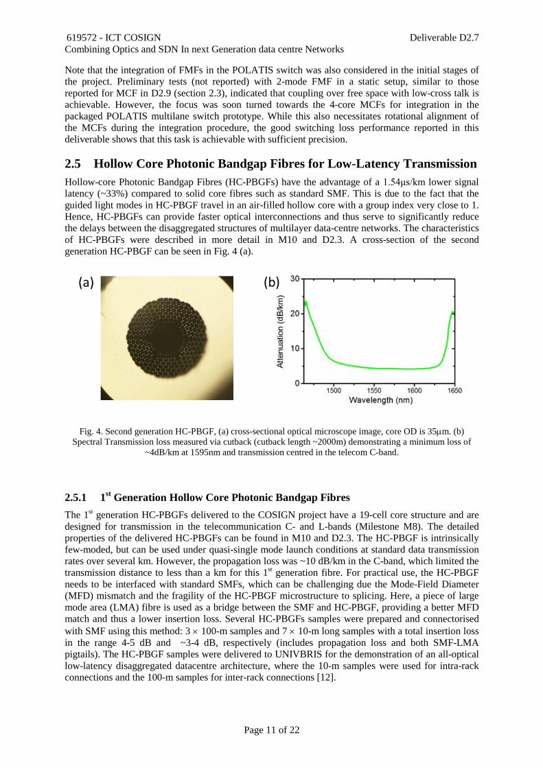
2.5 Hollow Core Photonic Bandgap Fibres for Low-Latency Transmission Hollow-core Photonic Bandgap Fibres (HC-PBGFs) have the advantage of a 1.54μs/km lower signal latency (~33%) compared to solid core fibres such as standard SMF. This is due to the fact that the guided light modes in HC-PBGF travel in an air-filled hollow core with a group index very close to 1. Hence, HC-PBGFs can provide faster optical interconnections and thus serve to significantly reduce the delays between the disaggregated structures of multilayer data-centre networks. The characteristics of HC-PBGFs were described in more detail in M10 and D2.3. A cross-section of the second generation HC-PBGF can be seen in Fig. 4 (a).
Fig. 4. Second generation HC-PBGF, (a) cross-sectional optical microscope image, core OD is 35µm. (b) Spectral Transmission loss measured via cutback (cutback length ~2000m) demonstrating a minimum loss of
~4dB/km at 1595nm and transmission centred in the telecom C-band.
2.5.1 1st Generation Hollow Core Photonic Bandgap Fibres The 1st generation HC-PBGFs delivered to the COSIGN project have a 19-cell core structure and are designed for transmission in the telecommunication C- and L-bands (Milestone M8). The detailed properties of the delivered HC-PBGFs can be found in M10 and D2.3. The HC-PBGF is intrinsically few-moded, but can be used under quasi-single mode launch conditions at standard data transmission rates over several km. However, the propagation loss was ~10 dB/km in the C-band, which limited the transmission distance to less than a km for this 1st generation fibre. For practical use, the HC-PBGF needs to be interfaced with standard SMFs, which can be challenging due the Mode-Field Diameter (MFD) mismatch and the fragility of the HC-PBGF microstructure to splicing. Here, a piece of large mode area (LMA) fibre is used as a bridge between the SMF and HC-PBGF, providing a better MFD match and thus a lower insertion loss. Several HC-PBGFs samples were prepared and connectorised with SMF using this method: 3 × 100-m samples and 7 × 10-m long samples with a total insertion loss in the range 4-5 dB and ~3-4 dB, respectively (includes propagation loss and both SMF-LMA pigtails). The HC-PBGF samples were delivered to UNIVBRIS for the demonstration of an all-optical low-latency disaggregated datacentre architecture, where the 10-m samples were used for intra-rack connections and the 100-m samples for inter-rack connections [12].

619572 - ICT COSIGN Deliverable D2.7 Combining Optics and SDN In next Generation data centre Networks
Page 12 of 22
2.5.2 2nd Generation Hollow Core Photonic Bandgap Fibres Several advances were subsequently achieved in the development of 2nd generation HC-PBGFs, as described in detail in D2.5. An image of the fibre-cross section with a 19-cell structure is shown in Fig. 4 (a). The propagation loss was significantly reduced, reaching a value as low as 4.2 dB/km in the C-band, cf. Fig. 4 (b). The fibre yield in a single draw was improved from about 2 km to 11 km. The connectorisation to standard SMFs was further improved, leading to insertion losses below 1 dB (this should be compared to the ~2 dB insertion loss per SMF-LMA pigtail of the 1st generation HC-PBGF samples). These significant improvements are promising for future use of HC-PBGFs in large data centres. In particular, the lower propagation losses allow for longer transmission distances, where the 30% relative latency reduction could become an even more significant advantage.
619572 - ICT COSIGN Deliverable D2.7 Combining Optics and SDN In next Generation data centre Networks
Page 13 of 22
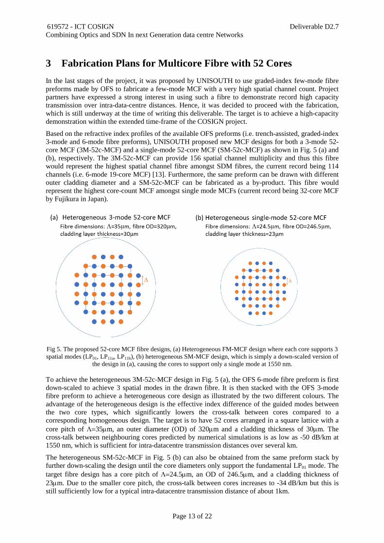
3 Fabrication Plans for Multicore Fibre with 52 Cores In the last stages of the project, it was proposed by UNISOUTH to use graded-index few-mode fibre preforms made by OFS to fabricate a few-mode MCF with a very high spatial channel count. Project partners have expressed a strong interest in using such a fibre to demonstrate record high capacity transmission over intra-data-centre distances. Hence, it was decided to proceed with the fabrication, which is still underway at the time of writing this deliverable. The target is to achieve a high-capacity demonstration within the extended time-frame of the COSIGN project.
Based on the refractive index profiles of the available OFS preforms (i.e. trench-assisted, graded-index 3-mode and 6-mode fibre preforms), UNISOUTH proposed new MCF designs for both a 3-mode 52-core MCF (3M-52c-MCF) and a single-mode 52-core MCF (SM-52c-MCF) as shown in Fig. 5 (a) and (b), respectively. The 3M-52c-MCF can provide 156 spatial channel multiplicity and thus this fibre would represent the highest spatial channel fibre amongst SDM fibres, the current record being 114 channels (i.e. 6-mode 19-core MCF) [13]. Furthermore, the same preform can be drawn with different outer cladding diameter and a SM-52c-MCF can be fabricated as a by-product. This fibre would represent the highest core-count MCF amongst single mode MCFs (current record being 32-core MCF by Fujikura in Japan).
Fig 5. The proposed 52-core MCF fibre designs, (a) Heterogeneous FM-MCF design where each core supports 3 spatial modes (LP01, LP11a, LP11b), (b) heterogeneous SM-MCF design, which is simply a down-scaled version of
the design in (a), causing the cores to support only a single mode at 1550 nm.
To achieve the heterogeneous 3M-52c-MCF design in Fig. 5 (a), the OFS 6-mode fibre preform is first down-scaled to achieve 3 spatial modes in the drawn fibre. It is then stacked with the OFS 3-mode fibre preform to achieve a heterogeneous core design as illustrated by the two different colours. The advantage of the heterogeneous design is the effective index difference of the guided modes between the two core types, which significantly lowers the cross-talk between cores compared to a corresponding homogeneous design. The target is to have 52 cores arranged in a square lattice with a core pitch of Λ=35µm, an outer diameter (OD) of 320µm and a cladding thickness of 30µm. The cross-talk between neighbouring cores predicted by numerical simulations is as low as -50 dB/km at 1550 nm, which is sufficient for intra-datacentre transmission distances over several km.
The heterogeneous SM-52c-MCF in Fig. 5 (b) can also be obtained from the same preform stack by further down-scaling the design until the core diameters only support the fundamental LP01 mode. The target fibre design has a core pitch of Λ=24.5µm, an OD of 246.5µm, and a cladding thickness of 23µm. Due to the smaller core pitch, the cross-talk between cores increases to -34 dB/km but this is still sufficiently low for a typical intra-datacentre transmission distance of about 1km.

619572 - ICT COSIGN Deliverable D2.7 Combining Optics and SDN In next Generation data centre Networks
Page 14 of 22
System experiments with data transmission are currently being planned with project partners to demonstrate the capacity of the fabricated fibres within the time-frame of the COSIGN project.
619572 - ICT COSIGN Deliverable D2.7 Combining Optics and SDN In next Generation data centre Networks
Page 15 of 22
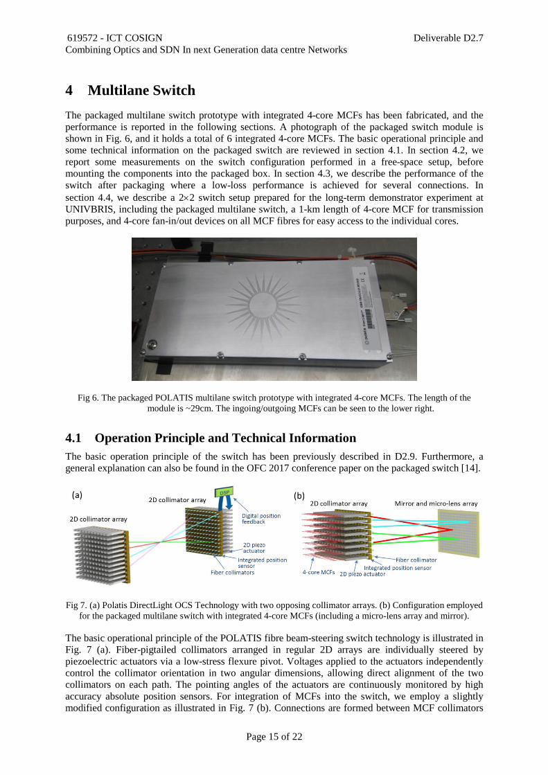
4 Multilane Switch The packaged multilane switch prototype with integrated 4-core MCFs has been fabricated, and the performance is reported in the following sections. A photograph of the packaged switch module is shown in Fig. 6, and it holds a total of 6 integrated 4-core MCFs. The basic operational principle and some technical information on the packaged switch are reviewed in section 4.1. In section 4.2, we report some measurements on the switch configuration performed in a free-space setup, before mounting the components into the packaged box. In section 4.3, we describe the performance of the switch after packaging where a low-loss performance is achieved for several connections. In section 4.4, we describe a 2×2 switch setup prepared for the long-term demonstrator experiment at UNIVBRIS, including the packaged multilane switch, a 1-km length of 4-core MCF for transmission purposes, and 4-core fan-in/out devices on all MCF fibres for easy access to the individual cores.
Fig 6. The packaged POLATIS multilane switch prototype with integrated 4-core MCFs. The length of the module is ~29cm. The ingoing/outgoing MCFs can be seen to the lower right.
4.1 Operation Principle and Technical Information The basic operation principle of the switch has been previously described in D2.9. Furthermore, a general explanation can also be found in the OFC 2017 conference paper on the packaged switch [14].
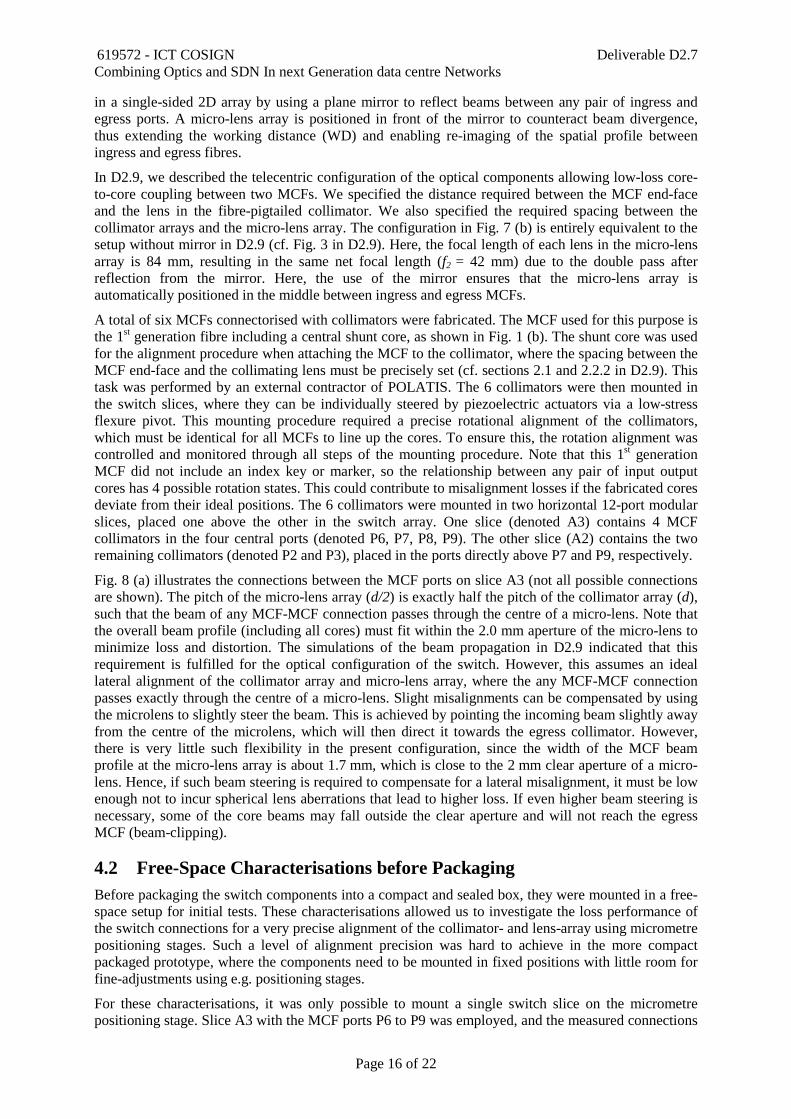
Fig 7. (a) Polatis DirectLight OCS Technology with two opposing collimator arrays. (b) Configuration employed for the packaged multilane switch with integrated 4-core MCFs (including a micro-lens array and mirror).
The basic operational principle of the POLATIS fibre beam-steering switch technology is illustrated in Fig. 7 (a). Fiber-pigtailed collimators arranged in regular 2D arrays are individually steered by piezoelectric actuators via a low-stress flexure pivot. Voltages applied to the actuators independently control the collimator orientation in two angular dimensions, allowing direct alignment of the two collimators on each path. The pointing angles of the actuators are continuously monitored by high accuracy absolute position sensors. For integration of MCFs into the switch, we employ a slightly modified configuration as illustrated in Fig. 7 (b). Connections are formed between MCF collimators
619572 - ICT COSIGN Deliverable D2.7 Combining Optics and SDN In next Generation data centre Networks
Page 16 of 22
in a single-sided 2D array by using a plane mirror to reflect beams between any pair of ingress and egress ports. A micro-lens array is positioned in front of the mirror to counteract beam divergence, thus extending the working distance (WD) and enabling re-imaging of the spatial profile between ingress and egress fibres.
In D2.9, we described the telecentric configuration of the optical components allowing low-loss core-to-core coupling between two MCFs. We specified the distance required between the MCF end-face and the lens in the fibre-pigtailed collimator. We also specified the required spacing between the collimator arrays and the micro-lens array. The configuration in Fig. 7 (b) is entirely equivalent to the setup without mirror in D2.9 (cf. Fig. 3 in D2.9). Here, the focal length of each lens in the micro-lens array is 84 mm, resulting in the same net focal length (f2 = 42 mm) due to the double pass after reflection from the mirror. Here, the use of the mirror ensures that the micro-lens array is automatically positioned in the middle between ingress and egress MCFs.
A total of six MCFs connectorised with collimators were fabricated. The MCF used for this purpose is the 1st generation fibre including a central shunt core, as shown in Fig. 1 (b). The shunt core was used for the alignment procedure when attaching the MCF to the collimator, where the spacing between the MCF end-face and the collimating lens must be precisely set (cf. sections 2.1 and 2.2.2 in D2.9). This task was performed by an external contractor of POLATIS. The 6 collimators were then mounted in the switch slices, where they can be individually steered by piezoelectric actuators via a low-stress flexure pivot. This mounting procedure required a precise rotational alignment of the collimators, which must be identical for all MCFs to line up the cores. To ensure this, the rotation alignment was controlled and monitored through all steps of the mounting procedure. Note that this 1st generation MCF did not include an index key or marker, so the relationship between any pair of input output cores has 4 possible rotation states. This could contribute to misalignment losses if the fabricated cores deviate from their ideal positions. The 6 collimators were mounted in two horizontal 12-port modular slices, placed one above the other in the switch array. One slice (denoted A3) contains 4 MCF collimators in the four central ports (denoted P6, P7, P8, P9). The other slice (A2) contains the two remaining collimators (denoted P2 and P3), placed in the ports directly above P7 and P9, respectively.
Fig. 8 (a) illustrates the connections between the MCF ports on slice A3 (not all possible connections are shown). The pitch of the micro-lens array (d/2) is exactly half the pitch of the collimator array (d), such that the beam of any MCF-MCF connection passes through the centre of a micro-lens. Note that the overall beam profile (including all cores) must fit within the 2.0 mm aperture of the micro-lens to minimize loss and distortion. The simulations of the beam propagation in D2.9 indicated that this requirement is fulfilled for the optical configuration of the switch. However, this assumes an ideal lateral alignment of the collimator array and micro-lens array, where the any MCF-MCF connection passes exactly through the centre of a micro-lens. Slight misalignments can be compensated by using the microlens to slightly steer the beam. This is achieved by pointing the incoming beam slightly away from the centre of the microlens, which will then direct it towards the egress collimator. However, there is very little such flexibility in the present configuration, since the width of the MCF beam profile at the micro-lens array is about 1.7 mm, which is close to the 2 mm clear aperture of a micro-lens. Hence, if such beam steering is required to compensate for a lateral misalignment, it must be low enough not to incur spherical lens aberrations that lead to higher loss. If even higher beam steering is necessary, some of the core beams may fall outside the clear aperture and will not reach the egress MCF (beam-clipping).
4.2 Free-Space Characterisations before Packaging Before packaging the switch components into a compact and sealed box, they were mounted in a free-space setup for initial tests. These characterisations allowed us to investigate the loss performance of the switch connections for a very precise alignment of the collimator- and lens-array using micrometre positioning stages. Such a level of alignment precision was hard to achieve in the more compact packaged prototype, where the components need to be mounted in fixed positions with little room for fine-adjustments using e.g. positioning stages.
For these characterisations, it was only possible to mount a single switch slice on the micrometre positioning stage. Slice A3 with the MCF ports P6 to P9 was employed, and the measured connections
619572 - ICT COSIGN Deliverable D2.7 Combining Optics and SDN In next Generation data centre Networks
Page 17 of 22
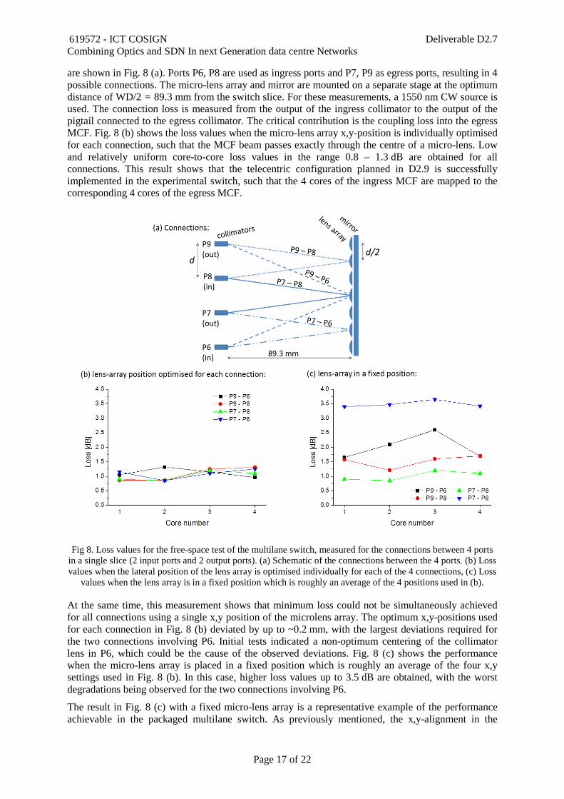
are shown in Fig. 8 (a). Ports P6, P8 are used as ingress ports and P7, P9 as egress ports, resulting in 4 possible connections. The micro-lens array and mirror are mounted on a separate stage at the optimum distance of WD/2 = 89.3 mm from the switch slice. For these measurements, a 1550 nm CW source is used. The connection loss is measured from the output of the ingress collimator to the output of the pigtail connected to the egress collimator. The critical contribution is the coupling loss into the egress MCF. Fig. 8 (b) shows the loss values when the micro-lens array x,y-position is individually optimised for each connection, such that the MCF beam passes exactly through the centre of a micro-lens. Low and relatively uniform core-to-core loss values in the range 0.8 – 1.3 dB are obtained for all connections. This result shows that the telecentric configuration planned in D2.9 is successfully implemented in the experimental switch, such that the 4 cores of the ingress MCF are mapped to the corresponding 4 cores of the egress MCF.
At the same time, this measurement shows that minimum loss could not be simultaneously achieved for all connections using a single x,y position of the microlens array. The optimum x,y-positions used for each connection in Fig. 8 (b) deviated by up to ~0.2 mm, with the largest deviations required for the two connections involving P6. Initial tests indicated a non-optimum centering of the collimator lens in P6, which could be the cause of the observed deviations. Fig. 8 (c) shows the performance when the micro-lens array is placed in a fixed position which is roughly an average of the four x,y settings used in Fig. 8 (b). In this case, higher loss values up to 3.5 dB are obtained, with the worst degradations being observed for the two connections involving P6.
The result in Fig. 8 (c) with a fixed micro-lens array is a representative example of the performance achievable in the packaged multilane switch. As previously mentioned, the x,y-alignment in the
Fig 8. Loss values for the free-space test of the multilane switch, measured for the connections between 4 ports in a single slice (2 input ports and 2 output ports). (a) Schematic of the connections between the 4 ports. (b) Loss values when the lateral position of the lens array is optimised individually for each of the 4 connections, (c) Loss
values when the lens array is in a fixed position which is roughly an average of the 4 positions used in (b).
619572 - ICT COSIGN Deliverable D2.7 Combining Optics and SDN In next Generation data centre Networks
Page 18 of 22
packaged switch is less precise with only minor room for fine-tuning, which can lead to a slightly different performance.
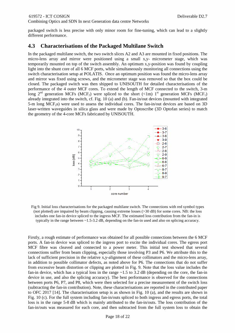
4.3 Characterisations of the Packaged Multilane Switch In the packaged multilane switch, the two switch slices A2 and A3 are mounted in fixed positions. The micro-lens array and mirror were positioned using a small x,y- micrometer stage, which was temporarily mounted on top of the switch assembly. An optimum x,y-position was found by coupling light into the shunt core of all 6 MCF ports, while simultaneously monitoring all connections using the switch characterisation setup at POLATIS. Once an optimum position was found the micro-lens array and mirror was fixed using screws, and the micrometer stage was removed so that the box could be closed. The packaged switch was then shipped to UNISOUTH for detailed characterisations of the performance of the 4 outer MCF cores. To extend the length of MCF connected to the switch, 3-m long 2nd generation MCFs (MCF2) were spliced to the short (<1m) 1st generation MCFs (MCF1) already integrated into the switch, cf. Fig. 10 (a) and (b). Fan-in/out devices (mounted with integrated 5-m long MCF2s) were used to assess the individual cores. The fan-in/out devices are based on 3D laser-written waveguides in silica glass and were made by Optoscribe (3D Optofan series) to match the geometry of the 4-core MCFs fabricated by UNISOUTH.
Fig 9. Initial loss characterisations for the packaged multilane switch. The connections with red symbol types (not plotted) are impaired by beam clipping, causing extreme losses (>30 dB) for some cores. NB: the loss includes one fan-in device spliced to the ingress MCF. The estimated loss contribution from the fan-in is typically in the range between ~1.5-3.2 dB, depending on the fan-in used and also on splicing accuracy.
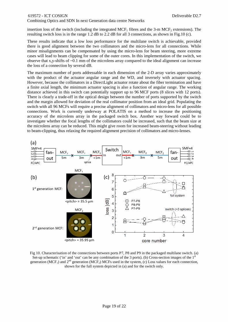
Firstly, a rough estimate of performance was obtained for all possible connections between the 6 MCF ports. A fan-in device was spliced to the ingress port to excite the individual cores. The egress port MCF fibre was cleaved and connected to a power meter. This initial test showed that several connections suffer from beam clipping, especially those involving P3 and P6. We attribute this to the lack of sufficient precision in the relative x,y-alignment of these collimators and the micro-lens array, in addition to possible collimator defects, as noted above for P6. The connections that do not suffer from excessive beam distortion or clipping are plotted in Fig. 9. Note that the loss value includes the fan-in device, which has a typical loss in the range ~1.5 to 3.2 dB (depending on the core, the fan-in device in use, and also the splicing accuracy). The best performance is observed for the connections between ports P6, P7, and P8, which were then selected for a precise measurement of the switch loss (subtracting the fan-in contribution). Note, these characterisations are reported in the contributed paper to OFC 2017 [14]. The characterisation setup is as shown in Fig. 10 (a), and the results are shown in Fig. 10 (c). For the full system including fan-in/outs spliced to both ingress and egress ports, the total loss is in the range 5-8 dB which is mainly attributed to the fan-in/outs. The loss contribution of the fan-in/outs was measured for each core, and then subtracted from the full system loss to obtain the
619572 - ICT COSIGN Deliverable D2.7 Combining Optics and SDN In next Generation data centre Networks
Page 19 of 22
insertion loss of the switch (including the integrated MCF1 fibres and the 3-m MCF2 extensions). The resulting switch loss is in the range 1.2 dB to 2.2 dB for all 3 connections, as shown in Fig.10 (c).
These results indicate that a low loss performance for the multilane switch is achievable, provided there is good alignment between the two collimators and the micro-lens for all connections. While minor misalignments can be compensated by using the micro-lens for beam steering, more extreme cases will lead to beam clipping for some of the outer cores. In this implementation of the switch, we observe that x,y-shifts of ~0.1 mm of the microlens array compared to the ideal alignment can increase the loss of a connection by several dB.
The maximum number of ports addressable in each dimension of the 2-D array varies approximately with the product of the actuator angular range and the WD, and inversely with actuator spacing. However, because the collimators in a DirectLight actuator rotate about the fiber termination and have a finite axial length, the minimum actuator spacing is also a function of angular range. The working distance achieved in this switch can potentially support up to 96 MCF ports (8 slices with 12 ports). There is clearly a trade-off in the optical design between the number of ports supported by the switch and the margin allowed for deviation of the real collimator position from an ideal grid. Populating the switch with all 96 MCFs will require a precise alignment of collimators and micro-lens for all possible connections. Work is currently underway at POLATIS on a method to increase the positioning accuracy of the microlens array in the packaged switch box. Another way forward could be to investigate whether the focal lengths of the collimators could be increased, such that the beam size at the microlens array can be reduced. This might give room for increased beam-steering without leading to beam-clipping, thus relaxing the required alignment precision of collimators and micro-lenses.
Fig 10. Characterisation of the connections between ports P7, P8 and P9 in the packaged multilane switch. (a) Set-up schematic (‘in’ and ‘out’ can be any combination of the 3 ports). (b) Cross-section images of the 1st
generation (MCF1) and 2nd generation (MCF2) MCFs used in the system, (c) Loss values for each connection, shown for the full system depicted in (a) and for the switch only.
619572 - ICT COSIGN Deliverable D2.7 Combining Optics and SDN In next Generation data centre Networks
Page 20 of 22
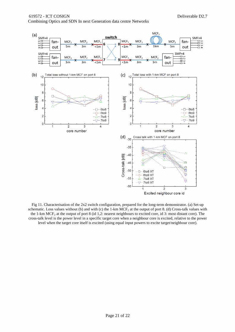
4.4 Multilane Switch Setup for the Long Term Demonstrator The target of the packaged multilane switch is to be an integrated part of the long-term demonstrators in the COSIGN project. In collaboration with UNIVBRIS, a setup including the multilane switch and a short MCF transmission span was planned. The setup is shown in Fig. 11 (a). The multilane switch is operated in a 2×2 configuration, involving two inputs (ports 6 and 7) and two outputs (ports 8 and 9). The possible connections are P6-P8, P6-P9, P7-P8 and P7-P9, which all have sufficiently good connection loss performance. A 1-km length of the 2nd generation 4-core MCF (MCF2) is spliced to port 8 (cf. fibre ‘X’ in D2.5, Table 2). Fan-in/outs are spliced to all MCFs to assess the individual cores. The losses are measured using a 1550 nm CW source and a power-meter. Fig. 11 shows the loss results without (b) and with (c) the 1-km MCF2 spliced between port 8 and the fan-in/out. In both cases, the total system loss is below 10 dB which was a requirement from UNIVBRIS. Previous characterisations (cf. D2.5) have shown that the propagation loss of the 1-km MCF2 is ~0.6-0.7 dB, which is a minor contribution to the system losses. The main loss is attributed to the fan-in/outs. However, the connections involving P6 show higher losses for some cores (as previously mentioned, the P6 collimator might have a defect). Finally, a characterisation of the cross-talk for each core was performed. The results for all of the 4 connections are plotted in Fig. 11 (d), showing a cross-talk level better than -34 dB. These measurements are obtained by exciting a single core at the input of the setup, cf. Fig. 11 (a), followed by detection of the power levels in the neighbour cores at the output. We expect that the cross-talk performance is mainly limited by the fan-in/out devices, since similar cross-talk levels are observed when splicing two fan-in/outs back-to-back. The cross-talk in the 1-km MCF is of the order -54 dB, cf. D2.5. Hence, we observe no detrimental cross-talk levels in the setup, and the overall performance is satisfactory for data transmission experiments.
After the characterisations, the complete setup was shipped to UNIVBRIS for inclusion in the long-term demonstrator, which was still under preparation at the time of submission of this document.
619572 - ICT COSIGN Deliverable D2.7 Combining Optics and SDN In next Generation data centre Networks
Page 21 of 22
Fig 11. Characterisation of the 2x2 switch configuration, prepared for the long-term demonstrator. (a) Set-up schematic. Loss values without (b) and with (c) the 1-km MCF2 at the output of port 8. (d) Cross-talk values with
the 1-km MCF2 at the output of port 8 (id 1,2: nearest neighbours to excited core, id 3: most distant core). The cross-talk level is the power level in a specific target core when a neighbour core is excited, relative to the power
level when the target core itself is excited (using equal input powers to excite target/neighbour core).

619572 - ICT COSIGN Deliverable D2.7 Combining Optics and SDN In next Generation data centre Networks
Page 22 of 22
5 Summary In this report, we have summarised the characteristics of a number of custom fibres which have been delivered to the project by OFS and UNISOUTH. These include MCFs, MEFs, and FMFs enabling transmission of multiple spatial channels in a single fibre, and also HC-PBGFs enabling low-latency transmission. The benefits of these fibres for optical data-centre interconnections have been demonstrated by project partners in system experiments. Additionally, a 2-mode 52-core MCF is currently being fabricated, aiming at a demonstration of record-high spatial channel count in a single fibre before the end of the project.
Furthermore, we have characterised the packaged multilane switch with integrated 4-core MCFs, which has been developed by POLATIS and UNISOUTH. The obtained performance demonstrates that low-loss multilane connections are achievable, and the capability of the switch has proved satisfactory for inclusion in the COSIGN long-term demonstrator experiment. The fabricated switch holds the potential for cross-connection of up to 96 integrated MCFs, which will necessitate implementing a number of planned design changes to achieve increased precision in the alignment of the optical switch components.