Embed Size (px)
Citation preview

Figure 1
Figure 2
Figure 3
Figure 3A
Instructions for Riser Kits
P/N: 102367 101975 101976 102576 101977 102577 101978 102578 102579 102580 101979 102581 102582 102583 102364
Tools required:
Steps: Installation must be performed by person possessing mechanical competence.
1.) With the white tape upward, apply approximately 77” of butyl sealant rope
(Figure 3A) around the perimeter of the adapter flange where the riser pipe will meet the flange (Fig.1) & (Fig. 2), overlapping and kneading the ends of the butyl rope together to ensure a water-tight seal.
2.) Remove the white tape from the sealant rope and discard the tape. 3.) With the (4) pre-drilled holes upward (Fig. 5) & (Fig. 10), center the riser pipe on
the adapter flange so the gap is even all of the way around. Do not apply downward pressure while adjusting the gap. When the even gap is achieved, lightly lower the riser pipe onto the butyl rope. As required, make final adjustment and apply firm downward pressure to seat the riser pipe into the butyl rope. Apply the pressure all around the riser pipe every 30 degrees.
4.) Locate the six (6) mounting holes on the inside perimeter of the adapter flange. Install six (6) screws to attach the riser pipe to the adapter flange. Drive the screws with the screw tilted upward following the pre-drilled hole until the head slightly compresses the adapter flange (Fig 3.). When properly tightened there will be approximately a ¼” gap between the riser flange and the riser pipe (Fig. 4). All six screws must be visible when complete (Fig. 5).
5.) Repeat steps 1 – 4 for each section for risers 23” tall and greater. NOTE: lower sections do not have pre-drilled holes, therefore space equally around inner perimeter.
How to Install the Safety Barrier 6.) Locate the six mounting slots on the safety barrier (Fig. 6). Insert the
safety barrier into the riser ensuring the six mounting slots align with the 6 screws (Fig 5), (Fig. 6) & (Fig. 7).
7.) Confirm all six slots are engaged with all six screws. While applying slight downward pressure, rotate the safety barrier clockwise, the direction the “LOCK ARROW” points. A slight rap with the palm of the hands in the safety barrier triangular openings will seat the safety barrier in place.
8.) Grasp the openings of the safety barrier and pull upward. It MUST NOT dislodge from the assembly. If all of the mounting tabs are not engaged with the screws, remove the safety barrier and repeat step 6 through step 8 until the safety barrier is secure.
CRITICAL SAFETY WARNING: Always securely attach Riser Cover to Riser by installing and tightening the (4) screws using the appropriate driver tool. Cover security must be checked after each tank servicing. Cover must be inspected regularly for damage and security. The secondary safety barrier must be securely fastened in place at
all times. The safety barrier must only be removed to gain entry into the tank by a properly credentialed professional donning appropriate safety gear.
An unsecured cover or secondary safety barrier is a serious safety risk.
Butyl Rope
CAUTION: INSTALLER AND SERVICE PERSONNEL MUST PLACE THIS GUIDE IN PLASTIC POUCH AND ENSURE IT IS ATTACHED TO THE SAFETY BARRIER AFTER INSTALLATION IS COMPLETE SEE FIG. 9
CAUTION: INSTALLER AND SERVICE PERSONNEL MUST PLACE THIS GUIDE IN PLASTIC POUCH AND ENSURE IT IS ATTACHED TO THE SAFETY BARRIER AFTER INSTALLATION IS COMPLETE
SEE FIG. 9
Printed on durable waterproof paper
• Electric Drill
• 5/32” drill bit (carbide tip if septic tank is concrete)
• #3 Phillips head driver bit
• Utility knife
• Safety glasses
• Gloves
*** Beware of sharp edges when handling components***
83”
77”
77”
77”
WARNING: FAILURE TO PROPERLY ENGAGE THE SAFTEY BARRIER WILL DEFEAT THE SAFTEY FEATURE OF THE DEVICE!

P/N: 102368 REV F
Figure 4
Figure 5
Figure 6
Figure 7
Figure 9
Figure 10
9.) Expose and clean a 32” x 32” square area on the top of the septic tank centered on the clean-
out opening on the tank. 10.) With the white tape upward, apply the butyl sealant rope around the groove on the bottom of
the adapter flange (Figure 3A), overlapping and kneading the ends of the butyl rope together (Fig. 8).
11.) Remove the white tape from the sealant rope and discard the tape. 12.) Center the riser assembly on the tank clean-out opening and apply pressure around the
perimeter of the base flange above the butyl sealant rope to compress sealant between the tank and the adapter flange.
13.) Drill (4) 5/32” diameter holes through the four corners of the adapter flange (Fig. 9) at least 1 3/4” deep into the tank cover. If the tank in made of concrete, use a carbide tip masonry bit.
14.) Fasten the base plate to the tank using four (4) enclosed blue screws. 15.) Backfill around riser with sand or washed stone to prevent movement from frost if applicable in
your climate.
16.) Always re-install (4) cover security screws and tighten with appropriate driver tool to secure Riser Cover to Riser Pipe (Fig.10) & (Fig. 11)
WARNING: FAILURE TO PROPERLY SECURE THE RISER COVER WILL CREATE A SERIOUS SAFETY RISK!
Figure 11
6
Mounting Slot
(4) Cover Screws into (4) pre-drilled holes
Figure 8
(4) Mounting Holes
Butyl Rope in Bottom Groove All Around
Screw through Hole in Pouch
Always Return Guide to Pouch after Installation or Servicing!
(4) pre-drilled holes for cover screws
P/N: 102368 REV F
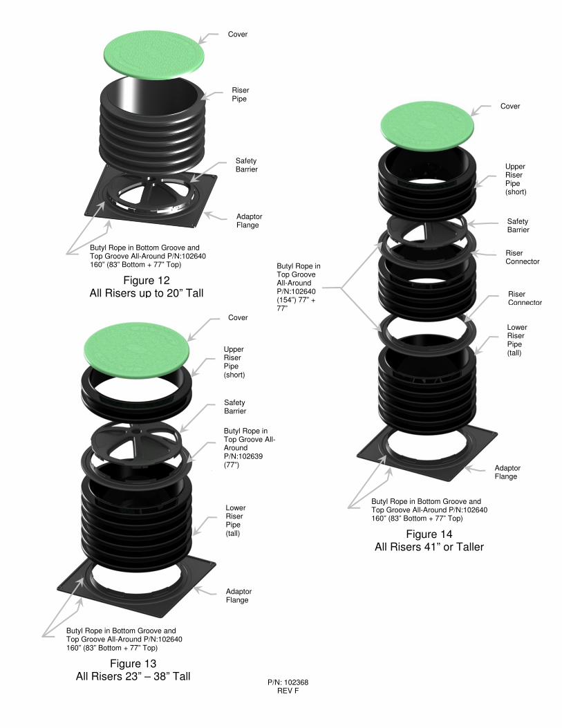
Cover
UpperRiser Pipe (short)
Safety Barrier
Butyl Rope in Top Groove All-Around P/N:102639 (77”)
Lower Riser Pipe (tall)
Butyl Rope in Bottom Groove and Top Groove All-Around P/N:102640 160” (83” Bottom + 77” Top)
Figure 13 All Risers 23” – 38” Tall
Cover
Upper Riser Pipe (short)
Safety Barrier
Riser Connector
Butyl Rope in Top Groove All-Around P/N:102640 (154”) 77” + 77”
Riser Connector
Lower Riser Pipe (tall)
Butyl Rope in Bottom Groove and Top Groove All-Around P/N:102640 160” (83” Bottom + 77” Top)
Figure 14 All Risers 41” or Taller
Cover
Riser Pipe
Safety Barrier
Butyl Rope in Bottom Groove and Top Groove All-Around P/N:102640 160” (83” Bottom + 77” Top)
Figure 12 All Risers up to 20” Tall
Adaptor Flange
Adaptor Flange
Adaptor Flange


![Drilling Riser[1]](https://img.pdfslide.us/doc/110x75/55267215550346d36e8b4d99/drilling-riser1.jpg)