Embed Size (px)
Citation preview
AFS Transactions 01-071 (Page 1 of 11)
Production Experience WithCompacted Graphite Iron Automotive Components
W. GuesserTupy Fundições, Joinville, Santa Catarina, Brazil
T. SchroederSinterCast Inc, Auburn Hills, Michigan
S. DawsonSinterCast Technologies AB, Katrineholm, Sweden
Copyright©2001 American Foundry Society
ABSTRACTIn response to OEM demands for more durable cylinder block and head materials, Tupy has developed process capability forseries production of compacted graphite iron (CGI). Prototype CGI block and head castings have provided 90% increase intensile strength and 40% increase in elastic modulus relative to the production gray iron castings. The present paper providesan overview of the properties of CGI and the process control requirements for the production of low nodularity CGImicrostructures without the use of titanium and without the risk of flake graphite formation. Product results are provided forfourteen different automotive castings.
INTRODUCTIONEmissions legislation and the demand for higher performance from smaller engines have together driven the development ofdiesel engine technology over the past ten years. One of the most significant of these developments has been the advent ofcommon rail and unit injector fuel management and delivery systems, which allow for higher cylinder pressures in directinjection diesel engines. The higher peak firing pressures provide more efficient combustion, improved performance,reduced emissions and quieter engine operation. At the same time, the increased firing pressures place increased mechanicalloads on the main bearing region of the cylinder block, potentially resulting in premature fatigue failures. The irreversibletrend toward higher peak firing pressures have prompted engine designers to seek stronger materials in order to meet theirdurability targets without increasing the size or weight of their engines.
Given that new engine programs are typically intended to last for approximately three vehicle generations, the chosen enginematerials not only need to satisfy current design criteria but must also provide the potential for future performanceimprovements without changing the overall block architecture. With at least 75% increase in ultimate tensile strength,35-40% increase in elastic modulus and approximately double the fatigue strength of gray cast iron, compacted graphite ironis ideally suited to meet the current and future requirements of diesel engine design. In response to production enquiries fromOEM’s in Europe, Asia and the Americas, Tupy Fundições has developed the capability for volume production of cylinderblocks and heads in compacted graphite iron. Based on experience from the production of CGI exhaust manifolds since1992, Tupy has implemented the SinterCast process control technology to meet the demands of increased production volume,increased part complexity and a narrower microstructure specification. This paper describes the control technology and theexperiences with prototype production.
COMPACTED GRAPHITE IRONAs shown in Figure 1, the graphite particles in compacted graphite iron appear as individual ‘worm-shaped’ or vermicularparticles. The particles are elongated and randomly oriented as in gray iron, however they are shorter and thicker, and haverounded edges. While the compacted graphite particles appear worm-shaped when viewed in two dimensions, deep-etchedscanning electron micrographs (Figure 2) show that the individual ‘worms’ are connected to their nearest neighbors withinthe eutectic cell. The complex coral-like graphite morphology, together with the rounded edges and irregular bumpy surfacesof the graphite particles, results in strong adhesion between the graphite and the iron matrix. The compacted graphitemorphology inhibits crack initiation and growth and is the source of the improved mechanical properties relative to gray iron.

AFS Transactions 01-071 (Page 2 of 11)
Figure 1: CGI microstructure containing 10% nodularity. Figure 2: Deep-etched SEM micrographs showthe complex coral-like graphite inthree-dimensions.
Compacted graphite iron invariably includes some nodular (spheroidal) graphite particles. As the nodularity increases, thestrength and stiffness also increase, but only at the expense of castability, machinability and thermal conductivity.The microstructure specification must therefore be chosen depending on both the production and performance requirementsof the product. For example, the production of exhaust manifolds at Tupy since 1992 was specified with up to 50%nodularity. For manifolds, the higher nodularity provides increased strength for supporting the exhaust system and alsofacilitates the flow of exhaust heat into the catalyst to achieve early light-off. The higher nodularity benefits the productwithout increasing the incidence of casting defects. In another example, Daimler/Chrysler [1] have shown that the ductilityprovided by up to 50% nodularity microstructures reduces cracking defects in bedplates. In this case the higher nodularity ispermissible because machining is limited to milling and short-hole drilling and the product is not thermally loaded.
In contrast to exhaust manifolds and bedplates, the geometric complexity and shrinkage tendencies of cylinder blocks andheads, combined with severe thermal and mechanical loading and extensive machining require microstructure control withinthe range of 0-20% nodularity. Combined with a 20% maximum nodularity for all performance-critical sections of the blockand head castings, it is also imperative that the microstructure not contain any flake graphite. The presence of even a smallamount of flake graphite results in an immediate 20-30% decrease in strength and stiffness promoting premature fieldfailures. For the reliable series production of CGI cylinder blocks and heads, the foundry process must therefore sustain thebalance between the onset of flake graphite formation on the one hand, and the optimization of castability, machinability andthermal conductivity on the other hand. This challenge defined the requirements of the process control system.

AFS Transactions 01-071 (Page 3 of 11)
Historically, the production of CGI exhaust manifolds at Tupy was facilitated by the addition of 0.10-0.15% titanium.The addition of titanium ‘poisons’ the graphite growth thus allowing safe compacted graphite iron production at highermagnesium contents. The higher magnesium ensures that graphite flakes will not grow while the titanium suppresses thegrowth of nodular graphite. While the titanium process can be used for the production of exhaust manifolds, the resultingformation of hard titanium carbonitride inclusions increases abrasive wear and cannot be tolerated in machining-intensivecomponents such as cylinder blocks and heads. The influence of the titanium on the machinability of CGI becomes evidentwhen it is realized that, for each 0.10% titanium addition, more than 1000 titanium carbonitride inclusions will be present ineach square millimeter of machined surface area. As shown in Figure 3 [2], even a small increase in the tramp titaniumcontent dramatically reduces tool life during continuous cutting operations such as cylinder boring. It was therefore decidedthat the existing titanium-based CGI production process could not be used for cylinder blocks and heads.
Figure 3: The addition of titanium dramatically reducesthe tool life of compacted graphite iron duringcarbide turning.

AFS Transactions 01-071 (Page 4 of 11)
Compacted graphite iron can be produced with varying pearlite contents to suit the intended application. Exhaust manifoldsrequire more than 95% ferrite to prevent high temperature growth. In contrast, cylinder blocks and heads are typicallyproduced with a predominantly pearlitic matrix to maximize strength and stiffness. Compacted graphite iron may bespecified with 60-80% pearlite to provide approximately the same hardness range (BHN 190-225) as conventional gray castiron. However, fully pearlitic specifications result in less product variation and provide superior mechanical properties.The mechanical and physical properties of CGI with 70% and 100% pearlite are summarized in Table 1. The data arerepresentative of a microstructure with 10% nodularity, as obtained from separately cast 25 mm diameter arbitration bars.
Table 1Mechanical and Physical Properties of 10% Nodularity CGI.
Property Test Method Temp(ºC)
70%Pearlite
100%Pearlite
Ultimate Tensile Strength (MPa) ASTM E 8M (25ºC) 25 420 450ASTM E 21 (100ºC & 300ºC) 100 415 430
300 375 4100.2% Yield Strength (MPa) ASTM E 8M (25ºC) 25 315 370
ASTM E21 (100ºC & 300ºC) 100 295 335300 284 320
Elastic Modulus (GPa) ASTM E 8M (25ºC) 25 145 145ASTM E 21 (100ºC & 300ºC) 100 140 140
300 130 130Elongation (%) ASTM E 8M (25ºC) 25 1.5 1.0
ASTM E21 (100ºC & 300ºC) 100 1.5 1.0300 1.0 1.0
Unnotched Fatigue Limit (MPa) Rotating-bending 25 195 2103000 rpm 100 185 190
300 165 175Endurance Ratio Fatigue Limit/UTS 25 0.46 0.44
100 0.45 0.44300 0.44 0.43
Thermal Conductivity (W/mºC) Comparative axial heat flow 25 37 36ASTM E 1225 100 37 36
300 36 35Thermal Expansion Coefficient Pushrod dilatometry 25 11.0 11.0(µm/mºC) DIN 51 045 100 11.5 11.5
300 12.0 12.0Poisson’s Ratio ASTM E 132 25 0.26 0.26
100 0.26 0.26300 0.27 0.27
0.2% Compressive Yield (MPa) ASTM E 9 (medium length) 25 400 430400 300 370
Density (g/cc) Displacement (750x25x25) mm 25 7.0-7.1 7.0-7.1Brinell Hardness (BHN) 10 mm diameter, 3000 kg load 25 190-225 207-255
PROCESS CONTROLThe control emphasis for the production of CGI engine blocks and heads was placed on the ability to achieve a lownodularity microstructure without allowing the formation of flake graphite. The two key elements in the successful processcontrol were the ability to accurately measure the behavior of the molten iron and to respond to the measured result before thecastings were produced. A two-step measure-and-correct production strategy was therefore adopted.
The process control is based on the thermal analysis of the molten iron after the initial base treatment with magnesium andinoculant ferroalloys. By evaluating the iron after the base treatment, the thermal analysis result indicates the combinedeffect of all process variations including charge materials, melting and holding practices, furnace tapping technique,

AFS Transactions 01-071 (Page 5 of 11)
differences in operator habit and the recovery of magnesium and inoculant. Depending on the result of the thermal analysis,corrective additions of magnesium and/or inoculant are added before the castings are produced. To facilitate the two-stepstrategy, the amount of magnesium and inoculant added in the sandwich base treatment are chosen to intentionally undertreatthe iron such that even if all variables combined to result in the highest possible recovery, the base treatment would onlyarrive at the desired start-cast composition.
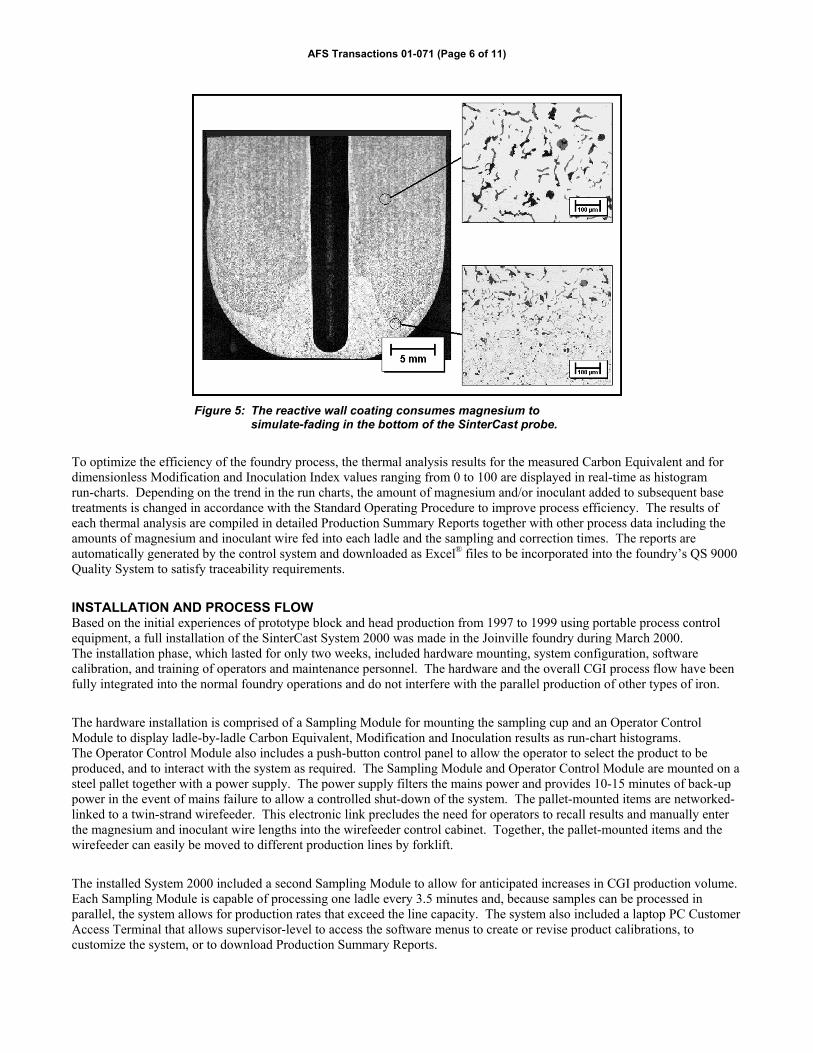
The 200 gram thermal analysis sample is obtained by immersing the sampling cup shown in Figure 4 into the molten ironafter the magnesium and inoculant base treatment has been made. During the three second immersion time, the walls of thesampling cup approach thermal equilibrium with the molten iron. In comparison to conventional thermal analysis sand cups,the thin-wall immersion sampler ensures a constant sample volume, prevents oxidation of the iron during pour-in filling andprovides a more accurate measurement of undercooling. In order to operate as close as possible to the border between CGIand gray iron, the inner walls of the sampling cup are treated with a reactive coating that consumes active magnesium.The thermal convection currents that develop within the spheroidally shaped sampling cup, rinse the molten iron along thecoated walls and cause the reacted metal to collect in a flow-separated region at the base of the cup. The reactive wallcoating is designed such that the active magnesium content in the flow-separated region at the bottom of the cup will beapproximately 0.003% less than that in the center of the sample. This amount of active magnesium consumption isapproximately the same as the amount of fade experienced in fifteen minutes.
Figure 4: The immersion-type sampling probe prevents oxidation of the sampled ironand provides thermal equilibrium between the vessel and the molten iron.
The sampling cup contains two thermocouples in a closed-end protective tube. During production, the thermocouples areextracted and re-used up to 200 times. One of the thermocouples is located at the bottom of the protective tube while theother is located in the thermal center of the sample. The etched cross section of a used sampling cup provided in Figure 5shows the protective thermocouple tube and the distinct difference between the solidification behavior of the bulk iron andthat of the flow-separated region. The loss of 0.003% active magnesium has resulted in the formation of undercooled D-typeflake graphite and, due to the reduced diffusion distances, a ferritic matrix. The formation of flake graphite during thesolidification in the sampling cup is measurable from the cooling curve of the bottom thermocouple prior to the eutecticminimum. In the simplest sense, the center thermocouple indicates the behavior of the iron at the start of casting while thebottom thermocouple simulates the solidification behavior at the end of casting. The two results are interpolated by theprocess controller to determine the necessary amount of corrective magnesium and inoculant cored wire additions prior tocasting in order to safely prevent flake graphite formation while providing a low-nodularity microstructure foroptimal castability.
(a) Immersion Sampler (b) Thermal convection currents
AFS Transactions 01-071 (Page 6 of 11)
Figure 5: The reactive wall coating consumes magnesium tosimulate-fading in the bottom of the SinterCast probe.
To optimize the efficiency of the foundry process, the thermal analysis results for the measured Carbon Equivalent and fordimensionless Modification and Inoculation Index values ranging from 0 to 100 are displayed in real-time as histogramrun-charts. Depending on the trend in the run charts, the amount of magnesium and/or inoculant added to subsequent basetreatments is changed in accordance with the Standard Operating Procedure to improve process efficiency. The results ofeach thermal analysis are compiled in detailed Production Summary Reports together with other process data including theamounts of magnesium and inoculant wire fed into each ladle and the sampling and correction times. The reports areautomatically generated by the control system and downloaded as Excel® files to be incorporated into the foundry’s QS 9000Quality System to satisfy traceability requirements.
INSTALLATION AND PROCESS FLOWBased on the initial experiences of prototype block and head production from 1997 to 1999 using portable process controlequipment, a full installation of the SinterCast System 2000 was made in the Joinville foundry during March 2000.The installation phase, which lasted for only two weeks, included hardware mounting, system configuration, softwarecalibration, and training of operators and maintenance personnel. The hardware and the overall CGI process flow have beenfully integrated into the normal foundry operations and do not interfere with the parallel production of other types of iron.
The hardware installation is comprised of a Sampling Module for mounting the sampling cup and an Operator ControlModule to display ladle-by-ladle Carbon Equivalent, Modification and Inoculation results as run-chart histograms.The Operator Control Module also includes a push-button control panel to allow the operator to select the product to beproduced, and to interact with the system as required. The Sampling Module and Operator Control Module are mounted on asteel pallet together with a power supply. The power supply filters the mains power and provides 10-15 minutes of back-uppower in the event of mains failure to allow a controlled shut-down of the system. The pallet-mounted items are networked-linked to a twin-strand wirefeeder. This electronic link precludes the need for operators to recall results and manually enterthe magnesium and inoculant wire lengths into the wirefeeder control cabinet. Together, the pallet-mounted items and thewirefeeder can easily be moved to different production lines by forklift.
The installed System 2000 included a second Sampling Module to allow for anticipated increases in CGI production volume.Each Sampling Module is capable of processing one ladle every 3.5 minutes and, because samples can be processed inparallel, the system allows for production rates that exceed the line capacity. The system also included a laptop PC CustomerAccess Terminal that allows supervisor-level to access the software menus to create or revise product calibrations, tocustomize the system, or to download Production Summary Reports.

AFS Transactions 01-071 (Page 7 of 11)
In the Joinville foundry the CGI production process begins with the melting of a low-sulfur base iron in 18 tonne corelessinduction furnaces. Sulfur is maintained below 0.020% using 2 tonne charges containing steel, CGI and/or ductile ironreturns and pig iron. Carbon raiser and silicon carbide alloys are used to control the Carbon Equivalent in the furnaces to4.40-4.50%. The CGI base treatment is performed by the sandwich treatment method, tapping directly from the meltingfurnaces. The treatment size has been varied between 800-1100kg depending on the size and number of castings poured.Standard 5% MgFeSi and Ce Mischmetal alloys are used in the base treatment process. The MgFeSi alloy amounts for CGIproduction are much less than those used in ductile iron treatments thus allowing the base treatment to be performed directlyin the pouring ladles without excessive splash or loss of Mg recovery. An alloy pocket constructed in the pouring ladles alsohelps to maintain a consistent and acceptable Mg recovery. Base treatment in the pouring ladles has reduced iron temperaturelosses and Mg-oxidation due to reladling and has provided a sound basis for wirefeeding corrections following thermalanalysis.
Following base treatment, the thermal analysis sample is obtained by immersing the sampling cup in a representative sampleof iron spooned from the ladle and the iron is transported to the wirefeeder correction station positioned near the desiredmolding line. While the sample solidifies, the ladle is deslagged and positioned beneath the splash lid and fume extractor forwirefeeding. The thermal analysis results for Carbon Equivalent, Modification and Inoculation are automatically comparedto the calibrated values for the casting to be produced and corrective additions of Mg and inoculant cored wire areautomatically determined. The operator is prompted with a simple Green/Red button selection to activate the wirefeeding.After wirefeeding the ladle is transferred directly to the molding line to begin casting. Deslagging and further sampling arenot required. Prototype castings have been produced in the Joinville foundry on both the Künkel Wagner molding line (100molds/hour, 1100x850x350mm flask size) and the BMD molding line (75 molds/hour, 1100x850x350mm flask size).
Following the initial experiences in the Joinville foundry, the System 2000 has been successfully transported to and operatedin the recently acquired Mauá Foundry in São Paulo. A similar CGI production process has been established using an 8tonne induction furnace and a 16 tonne arc furnace for base iron preparation and pouring on the Jolt/Squeeze molding line(1473x1143x460mm flask size). Production plans have been formalised to construct a high volume CGI series productionline for up to 350,000 flasks per year in the Mauá facility.
PROTOTYPE BLOCK AND HEAD RESULTSTo date, a total of fourteen different castings have been produced in CGI for process validation and OEM customerevaluation. With the exception of one bedplate casting, which had a 0-50% nodularity specification, all of the CGI castingswere produced with a 0-20% nodularity specification. Each of the fourteen parts were cast in the existing gray iron patternswithout incidence of internal porosity or surface shrinkage defects. The various CGI prototype parts are listed in Table 2.
Table 2Summary of prototype castings produced in compacted graphite iron.
Component Detail Tupy Part
Number
Casting
Weight
(kg)
Parts/
Mold
Mold
Weight
(kg)Cylinder Head 6,0 liter I6 25.04.006 55,1 2 158,2Cylinder Head 5,9 liter I6 81.04.013 91,2 2 243,5Cylinder Head 7,3 liter V8 81.09.004 57,5 2 135Cylinder Block I4 81.12.001 49,3 4 244Cylinder Block 5,9 liter I6 81.04.010 152,6 1 195Cylinder Head 5,9 liter I6 81.04.005 70 1 102Cylinder Block 4.1 liter I4 25.01.013 123 1 165Bearing Cap 4,1 liter I4 20.20.017 12,8 7 141Timing Cover 4,1 liter I4 - 1Bedplate I4 80.46.004 36 6 270Cylinder Block 1 liter I4 25.07.003 37 4 213Cylinder Block 12.0 liter I6 BR460 392 1 430Cylinder Head 12.0 liter ind. 25.04.014 16 3 67Cylinder Block 7.3 liter V8 81.09.003 150 1 207

AFS Transactions 01-071 (Page 8 of 11)
Depending on the needs of the product, the castings were produced with different pearlite contents according to ASTMA842-85 grades 300 to 450. All castings were produced from a similar base iron chemistry containing approximately0.45% manganese. Depending on the specification of the casting, the pearlitic grades were stabilized by ladle additions ofmetallic copper and tin to achieve 0.45-0.60% Cu and 0.05-0.08% Sn. These additions were sufficient to provide 70-90%pearlitic matrices with 190-240 BHN. For the specific case of the ferritic-pearlitic 12.0 liter individual cylinder head and thebedplate, the base iron copper and tin contents of 0.004% and 0.006% respectively were sufficient to satisfy the 30-50%pearlite specification. As shown in Figure 6, both tensile strength and Brinell hardness vary linearly with pearlite content.This linear behavior has also been shown to exist in specimens obtained from test bars [3].
Figure 6: Ultimate tensile strength and hardness as a function of pearlite content.
The ultimate tensile and yield strengths for the CGI castings and the corresponding tensile strengths for gray iron partsproduced in the same molds are shown in Figures 7 and 8. On average, the pearlitic parts shown in Figure 7 provide a 90%increase in tensile strength relative to their gray iron counterparts. All tensile results were obtained from test bars sectioneddirectly from the same locations in the gray iron and CGI castings.
Figure 7: Ultimate tensile strength for pearlitic parts ASTM Grades 400-450.

AFS Transactions 01-071 (Page 9 of 11)
Figure 8: Ultimate tensile strength for ferritic-pearlitic partsASTM Grade 300-350.
Representative values of the elastic modulus of CGI were obtained for specimens sectioned from the 12 liter engine blockand from Y-blocks and cylindrical test bars. The data shown in Figure 9 indicate that the elastic modulus is relativelyinsensitive to changes in section thickness or cooling rate. Typical elastic modulus values for CGI are approximately150 GPa while the elastic modulus for gray iron samples extracted from the same region of the casting is approximately100-110 GPa.
Figure 9: Elastic modulus of CGI and gray iron samples from the mainbearing of the 12.0 liter cylinder block and from test pieces.
The microstructure of compacted graphite iron is influenced by cooling rate, with faster cooling rates promoting an increasein nodularity. While cooling rates generally correlate well with wall thickness, mold filling patterns also influence thecooling rate, especially in complex castings such as cylinder blocks. As a result, some 3 -5 mm walls located near in-gatesmay actually cool more slowly than thicker walls located elsewhere. For most cylinder block castings, walls thicker thanapproximately 5 mm will cool slowly enough to meet the 0-20% nodularity specification in the presence of good processcontrol. Thinner walls, which are typically restricted to outer walls, webs or ribs, may contain 30-50% nodularity, which is

AFS Transactions 01-071 (Page 10 of 11)
not detrimental to either castability or performance. The influence of wall thickness on microstructure and mechanicalproperties is illustrated for a 1.0 liter I-4 cylinder block in Figure 10. This figure shows that even for a small block casting,with a relatively small thermal mass, the nodularity in the 4.5 mm wall is only 25% while that in the 9 and 24 mm walls is15% and 10% respectively. In consideration of the machining stock that is applied to as-cast components, it is evident fromthis example that all performance and machining critical sections including cylinder bores, main bearing, top deck and panrail behave as “thick walls” and, with proper process control, can be held within the 0-20% nodularity specification.
Figure 10: Tensile strength and microstructure as a function of sectionthickness in a 1.0 liter I-4 cylinder block.
The residual stress has been measured using strain gauges for In-line and V-type cylinder blocks and cylinder heads within-mold cooling times ranging from 1.5 to 4.0 hours. The measured micro-strain values for a 7.8 liter V-8 block with 1.5hours in-mold cooling are compared to typical results from the standard gray iron production castings in Table 3. It isevident from these data that the differences between the two materials are not significant and this is confirmed bydimensional measurements which show no difference between the CGI and gray iron castings after machining. Assuming amicro-strain of 500, and taking into account an 80% increase in tensile strength (from 250 to 450 MPa) and a 40% increase inelastic modulus (from 110 to 150 GPa) for CGI over gray iron, the ratio of residual stress-to-ultimate tensile strength isapproximately 0.20 for both materials. From the direct micro-strain measurements and calculations it has been confirmedthat no process modifications are required for the transition from gray iron to CGI series production.
Table 3Residual Micro-strain measurements for 7.3 liter V-8 Cylinder Blocks Cast in CGI and Gray Iron.
Residual Strain (10-6)Measurement LocationCGI Gray (Prod’n)
Inside cylinder No. 3 +261 +506Inside cylinder No. 4 +267 +480Main bearing No. 2 +320 +577Pan rail, crank No. 3 -564 -1029Pan rail, crank No. 6 -523 -1076Side face, near hole -56 -76Side face, near hole -123 -74Firedeck, between cyl. 3 and 5 -68 -96Firedeck -811 -743Firedeck -434 -500
Note: (+) tensile, (-) compressive

AFS Transactions 01-071 (Page 11 of 11)
CONCLUSIONFollowing the production of compacted graphite iron exhaust manifolds since 1992, and prompted by OEM customerenquiries for CGI cylinder blocks and heads, Tupy initiated a programme to extend its production capability in 1997.Since that time, a total of fourteen different blocks, heads and bedplate components have been successfully produced in CGIusing existing gray iron tooling and core processes. All parts have been produced in the 0-20% nodularity range incompliance with the ASTM A842-85 specification.
In order to meet the more stringent production demands of complex castings such as blocks and heads, which must beproduced without the use of titanium to facilitate high volume machining, the foundry adopted an on-line measure-and-correct process control strategy. The process control system is integrated into the existing process flow and is operated by thenormal foundry operators. The consistency in the as-cast products has resulted in an average 90% increase in tensile strengthand 40% increase in elastic modulus compared to gray iron components cast from the same patterns.
REFERENCESDawson, S., “Compacted Graphite Iron: Mechanical and Physical Properties for Engine Design”, VDI Conference on
Materials in Powertrain (Werkstoff und Automobilantrieb), Dresden, Germany, (October 1999)Dawson, S., Hollinger I., Robbins, M., Daeth, J., Reuter, U., and Schmidt, H. “The Effect of Metallurgical Variables on the
Machinability of Compacted Graphite Iron”, Presented at SAE International Congress, Detroit, (March 2001)Warrick, R.J., Ellis, G.G., Grupke, C.C., Khamseh, A.R., McLachlan T.H. and Gerkits C., “Development and Application of
Enhanced Compacted Graphite Iron for the Bedplate of the New Chrysler 4.7 Liter V-8 Engine”, SAE Paper pp 99-144