Embed Size (px)
Citation preview
AFRL-AFOSR-UK-TR-2015-0045
Quantum Photonics Beyond Conventional Computing
Jeremy OBrien THE UNIVERSITY OF BRISTOL
07/10/2015 Final Report
DISTRIBUTION A: Distribution approved for public release.
AF Office Of Scientific Research (AFOSR)/ IOEArlington, Virginia 22203
Air Force Research Laboratory
Air Force Materiel Command

REPORT DOCUMENTATION PAGE Form Approved OMB No. 0704-0188
Public reporting burden for this collection of information is estimated to average 1 hour per response, including the time for reviewing instructions, searching existing data sources, gathering and maintaining the data needed, and completing and reviewing the collection of information. Send comments regarding this burden estimate or any other aspect of this collection of information, including suggestions for reducing the burden, to Department of Defense, Washington Headquarters Services, Directorate for Information Operations and Reports (0704-0188), 1215 Jefferson Davis Highway, Suite 1204, Arlington, VA 22202-4302. Respondents should be aware that notwithstanding any other provision of law, no person shall be subject to any penalty for failing to comply with a collection of information if it does not display a currently valid OMB control number. PLEASE DO NOT RETURN YOUR FORM TO THE ABOVE ADDRESS. 1. REPORT DATE (DD-MM-YYYY)
10 July 2015 2. REPORT TYPE
Final 3. DATES COVERED (From – To)
15 Mar 2012 – 15 Mar 2015 4. TITLE AND SUBTITLE
Quantum Photonics Beyond Conventional Computing
5a. CONTRACT NUMBER
FA8655-12-1-2077 5b. GRANT NUMBER GRANT 122077 5c. PROGRAM ELEMENT NUMBER 61102F
6. AUTHOR(S) OBrien, Jeremy
5d. PROJECT NUMBER
5d. TASK NUMBER
5e. WORK UNIT NUMBER
7. PERFORMING ORGANIZATION NAME(S) AND ADDRESS(ES)THE UNIVERSITY OF BRISTOL SENATE HOUSE, TYNDALL AVENUE BRISTOL BS8 1TH UNITED KINGDOM
8. PERFORMING ORGANIZATION REPORT NUMBER
N/A
9. SPONSORING/MONITORING AGENCY NAME(S) AND ADDRESS(ES) EOARD Unit 4515 APO AE 09421-4515
10. SPONSOR/MONITOR’S ACRONYM(S) AFRL/AFOSR/IOE (EOARD)
11. SPONSOR/MONITOR’S REPORT NUMBER(S)
AFRL-AFOSR-UK-TR-2015-0045
12. DISTRIBUTION/AVAILABILITY STATEMENT Distribution A: Approved for public release; distribution is unlimited. 13. SUPPLEMENTARY NOTES
14. ABSTRACT This project builds toward a simplified quantum information processing device which, though simpler than a universal quantum computer, uses far fewer resources and can still outperform any classical device for a particular specific task. Using the evolution of photons through linear optical networks for computation, we introduce the Boson Sampling model of linear optical quantum computing, realizing the first universally reconfigurable linear optical circuit, and demonstrate how the device can perform quantum simulations of the evolution of vibrational wave-packets in molecules, suggesting that such an approach could yield the first meaningful quantum simulations which are not possible with classical computation.
15. SUBJECT TERMS EOARD, quantum photonics, quantum information processing, boson sampling
16. SECURITY CLASSIFICATION OF: 17. LIMITATION OF ABSTRACT
SAR
18, NUMBER OF PAGES
17
19a. NAME OF RESPONSIBLE PERSONVictor Putz a. REPORT
UNCLAS b. ABSTRACT
UNCLAS c. THIS PAGE
UNCLAS 19b. TELEPHONE NUMBER (Include area code)
+44 (0)1895 616013
Standard Form 298 (Rev. 8/98) Prescribed by ANSI Std. Z39-18
Close out report: FA8655-12-1-2077
Quantum photonicsbeyond
conventional computing
Distribution A: Approved for public release; distribution is unlimited.
CONTENTS
I. Introduction 3
II. Boson Sampling 3
III. Active temporal multiplexing of single photons 4
IV. Boson sampling from a Gaussian state 5
V. Verification of Boson Sampling 6
VI. Quantum-enhanced tomography of unitary processes 8
VII. Universal linear optics 9
VIII. Quantum simulation of harmonic phonons 11
IX. Conclusions 13
X. List of publications supported by USAF 13
References 13
2
Distribution A: Approved for public release; distribution is unlimited.
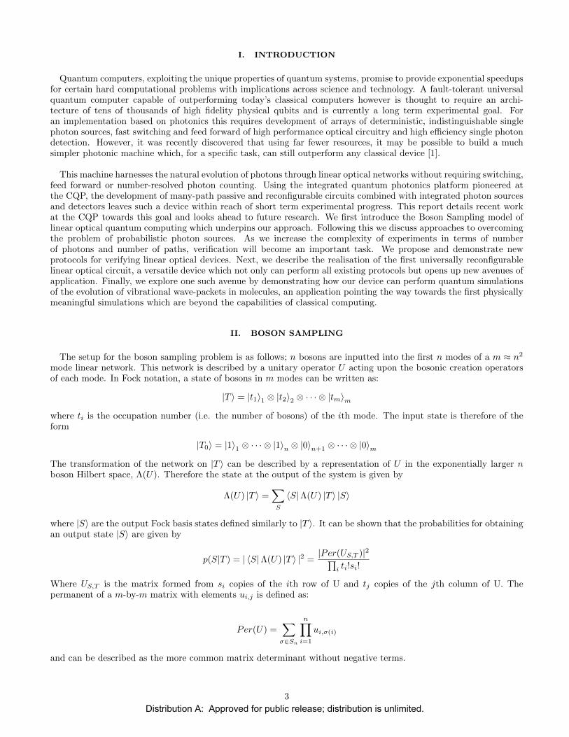
I. INTRODUCTION
Quantum computers, exploiting the unique properties of quantum systems, promise to provide exponential speedupsfor certain hard computational problems with implications across science and technology. A fault-tolerant universalquantum computer capable of outperforming today’s classical computers however is thought to require an archi-tecture of tens of thousands of high fidelity physical qubits and is currently a long term experimental goal. Foran implementation based on photonics this requires development of arrays of deterministic, indistinguishable singlephoton sources, fast switching and feed forward of high performance optical circuitry and high efficiency single photondetection. However, it was recently discovered that using far fewer resources, it may be possible to build a muchsimpler photonic machine which, for a specific task, can still outperform any classical device [1].
This machine harnesses the natural evolution of photons through linear optical networks without requiring switching,feed forward or number-resolved photon counting. Using the integrated quantum photonics platform pioneered atthe CQP, the development of many-path passive and reconfigurable circuits combined with integrated photon sourcesand detectors leaves such a device within reach of short term experimental progress. This report details recent workat the CQP towards this goal and looks ahead to future research. We first introduce the Boson Sampling model oflinear optical quantum computing which underpins our approach. Following this we discuss approaches to overcomingthe problem of probabilistic photon sources. As we increase the complexity of experiments in terms of numberof photons and number of paths, verification will become an important task. We propose and demonstrate newprotocols for verifying linear optical devices. Next, we describe the realisation of the first universally reconfigurablelinear optical circuit, a versatile device which not only can perform all existing protocols but opens up new avenues ofapplication. Finally, we explore one such avenue by demonstrating how our device can perform quantum simulationsof the evolution of vibrational wave-packets in molecules, an application pointing the way towards the first physicallymeaningful simulations which are beyond the capabilities of classical computing.
II. BOSON SAMPLING
The setup for the boson sampling problem is as follows; n bosons are inputted into the first n modes of a m ≈ n2
mode linear network. This network is described by a unitary operator U acting upon the bosonic creation operatorsof each mode. In Fock notation, a state of bosons in m modes can be written as:
|T 〉 = |t1〉1 ⊗ |t2〉2 ⊗ · · · ⊗ |tm〉mwhere ti is the occupation number (i.e. the number of bosons) of the ith mode. The input state is therefore of theform
|T0〉 = |1〉1 ⊗ · · · ⊗ |1〉n ⊗ |0〉n+1 ⊗ · · · ⊗ |0〉mThe transformation of the network on |T 〉 can be described by a representation of U in the exponentially larger nboson Hilbert space, Λ(U). Therefore the state at the output of the system is given by
Λ(U) |T 〉 =∑
S
〈S|Λ(U) |T 〉 |S〉
where |S〉 are the output Fock basis states defined similarly to |T 〉. It can be shown that the probabilities for obtainingan output state |S〉 are given by
p(S|T ) = | 〈S|Λ(U) |T 〉 |2 =|Per(US,T )|2∏
i ti!si!
Where US,T is the matrix formed from si copies of the ith row of U and tj copies of the jth column of U. Thepermanent of a m-by-m matrix with elements ui,j is defined as:
Per(U) =∑
σ∈Sn
n∏
i=1
ui,σ(i)
and can be described as the more common matrix determinant without negative terms.
3
Distribution A: Approved for public release; distribution is unlimited.
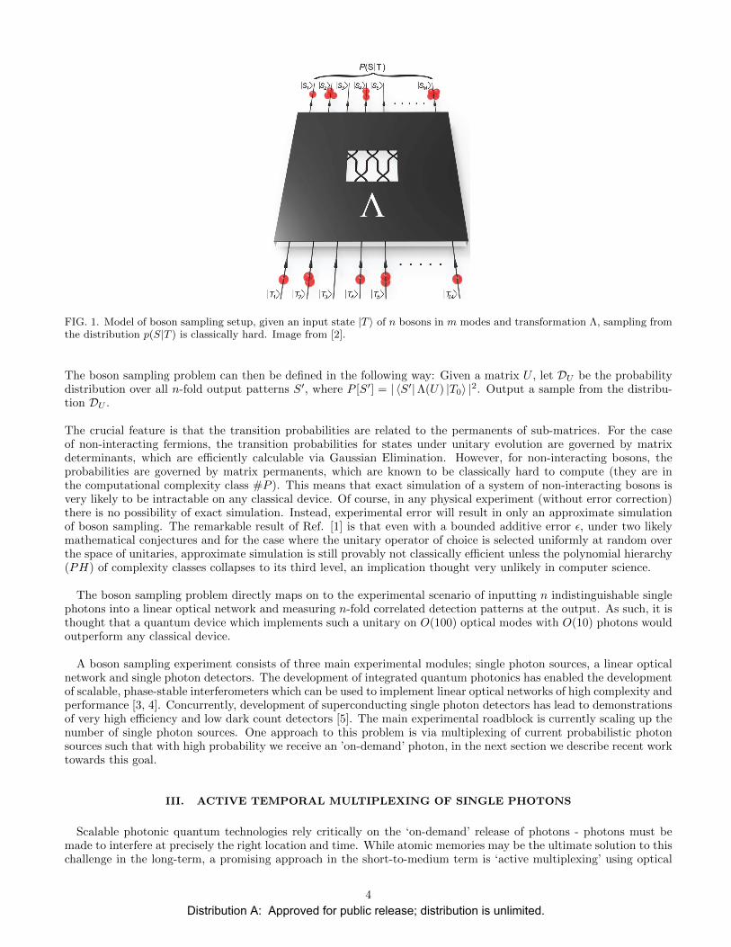
FIG. 1. Model of boson sampling setup, given an input state |T 〉 of n bosons in m modes and transformation Λ, sampling fromthe distribution p(S|T ) is classically hard. Image from [2].
The boson sampling problem can then be defined in the following way: Given a matrix U , let DU be the probabilitydistribution over all n-fold output patterns S′, where P [S′] = | 〈S′|Λ(U) |T0〉 |2. Output a sample from the distribu-tion DU .
The crucial feature is that the transition probabilities are related to the permanents of sub-matrices. For the caseof non-interacting fermions, the transition probabilities for states under unitary evolution are governed by matrixdeterminants, which are efficiently calculable via Gaussian Elimination. However, for non-interacting bosons, theprobabilities are governed by matrix permanents, which are known to be classically hard to compute (they are inthe computational complexity class #P ). This means that exact simulation of a system of non-interacting bosons isvery likely to be intractable on any classical device. Of course, in any physical experiment (without error correction)there is no possibility of exact simulation. Instead, experimental error will result in only an approximate simulationof boson sampling. The remarkable result of Ref. [1] is that even with a bounded additive error ε, under two likelymathematical conjectures and for the case where the unitary operator of choice is selected uniformly at random overthe space of unitaries, approximate simulation is still provably not classically efficient unless the polynomial hierarchy(PH) of complexity classes collapses to its third level, an implication thought very unlikely in computer science.
The boson sampling problem directly maps on to the experimental scenario of inputting n indistinguishable singlephotons into a linear optical network and measuring n-fold correlated detection patterns at the output. As such, it isthought that a quantum device which implements such a unitary on O(100) optical modes with O(10) photons wouldoutperform any classical device.
A boson sampling experiment consists of three main experimental modules; single photon sources, a linear opticalnetwork and single photon detectors. The development of integrated quantum photonics has enabled the developmentof scalable, phase-stable interferometers which can be used to implement linear optical networks of high complexity andperformance [3, 4]. Concurrently, development of superconducting single photon detectors has lead to demonstrationsof very high efficiency and low dark count detectors [5]. The main experimental roadblock is currently scaling up thenumber of single photon sources. One approach to this problem is via multiplexing of current probabilistic photonsources such that with high probability we receive an ’on-demand’ photon, in the next section we describe recent worktowards this goal.
III. ACTIVE TEMPORAL MULTIPLEXING OF SINGLE PHOTONS
Scalable photonic quantum technologies rely critically on the ‘on-demand’ release of photons - photons must bemade to interfere at precisely the right location and time. While atomic memories may be the ultimate solution to thischallenge in the long-term, a promising approach in the short-to-medium term is ‘active multiplexing’ using optical
4
Distribution A: Approved for public release; distribution is unlimited.
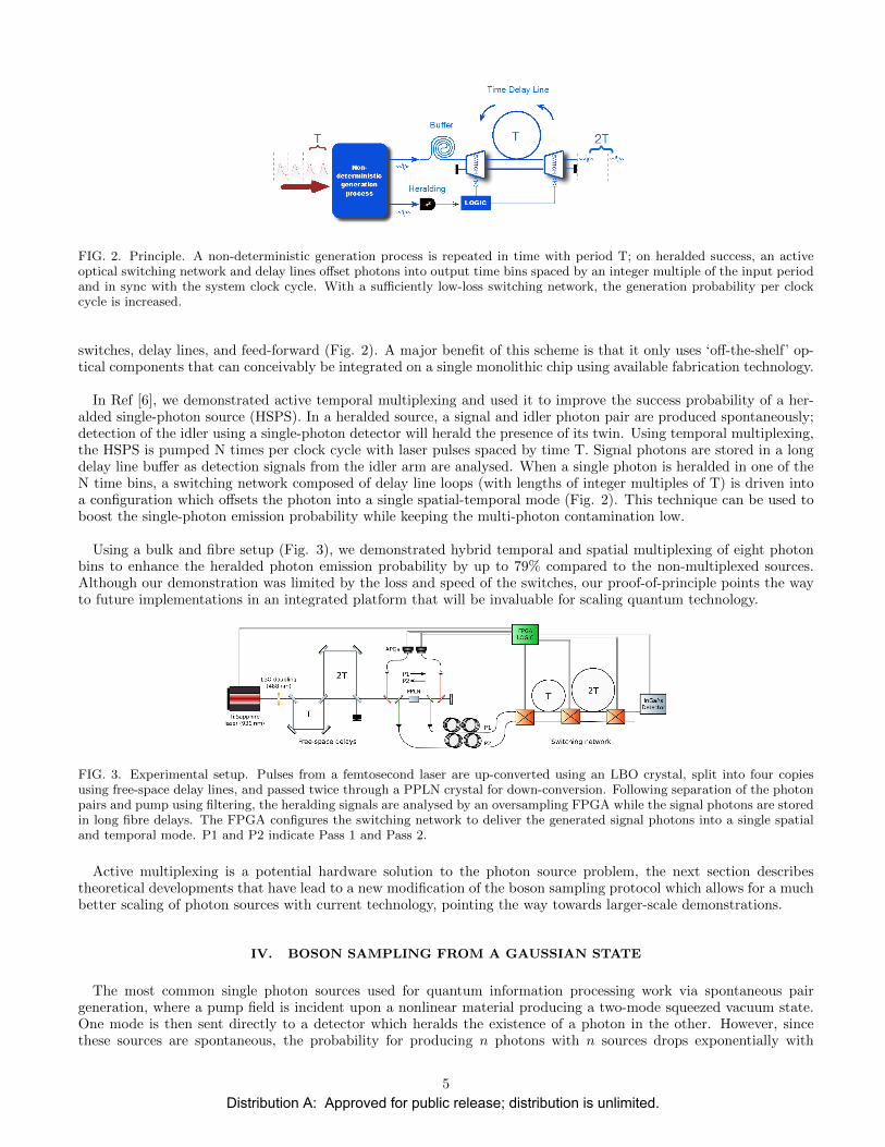
FIG. 2. Principle. A non-deterministic generation process is repeated in time with period T; on heralded success, an activeoptical switching network and delay lines offset photons into output time bins spaced by an integer multiple of the input periodand in sync with the system clock cycle. With a sufficiently low-loss switching network, the generation probability per clockcycle is increased.
switches, delay lines, and feed-forward (Fig. 2). A major benefit of this scheme is that it only uses ‘off-the-shelf’ op-tical components that can conceivably be integrated on a single monolithic chip using available fabrication technology.
In Ref [6], we demonstrated active temporal multiplexing and used it to improve the success probability of a her-alded single-photon source (HSPS). In a heralded source, a signal and idler photon pair are produced spontaneously;detection of the idler using a single-photon detector will herald the presence of its twin. Using temporal multiplexing,the HSPS is pumped N times per clock cycle with laser pulses spaced by time T. Signal photons are stored in a longdelay line buffer as detection signals from the idler arm are analysed. When a single photon is heralded in one of theN time bins, a switching network composed of delay line loops (with lengths of integer multiples of T) is driven intoa configuration which offsets the photon into a single spatial-temporal mode (Fig. 2). This technique can be used toboost the single-photon emission probability while keeping the multi-photon contamination low.
Using a bulk and fibre setup (Fig. 3), we demonstrated hybrid temporal and spatial multiplexing of eight photonbins to enhance the heralded photon emission probability by up to 79% compared to the non-multiplexed sources.Although our demonstration was limited by the loss and speed of the switches, our proof-of-principle points the wayto future implementations in an integrated platform that will be invaluable for scaling quantum technology.
FIG. 3. Experimental setup. Pulses from a femtosecond laser are up-converted using an LBO crystal, split into four copiesusing free-space delay lines, and passed twice through a PPLN crystal for down-conversion. Following separation of the photonpairs and pump using filtering, the heralding signals are analysed by an oversampling FPGA while the signal photons are storedin long fibre delays. The FPGA configures the switching network to deliver the generated signal photons into a single spatialand temporal mode. P1 and P2 indicate Pass 1 and Pass 2.
Active multiplexing is a potential hardware solution to the photon source problem, the next section describestheoretical developments that have lead to a new modification of the boson sampling protocol which allows for a muchbetter scaling of photon sources with current technology, pointing the way towards larger-scale demonstrations.
IV. BOSON SAMPLING FROM A GAUSSIAN STATE
The most common single photon sources used for quantum information processing work via spontaneous pairgeneration, where a pump field is incident upon a nonlinear material producing a two-mode squeezed vacuum state.One mode is then sent directly to a detector which heralds the existence of a photon in the other. However, sincethese sources are spontaneous, the probability for producing n photons with n sources drops exponentially with
5
Distribution A: Approved for public release; distribution is unlimited.

FIG. 4. Boson sampling from a gaussian state. n2 two-mode squeezers are used as single photon sources, with half the modessent to heralding detectors and the other half sent through a linear optical unitary.
n. While deterministic single photon sources based on two-level emitters or multiplexing as described above arein development, they are not currently a short term solution. However, a simple alleviation to this problem, whichretains the complexity implications of the original protocol is to add many more sources so that there is a spontaneoussource at each of the n2 inputs to our circuit, rather than just the first n [7].
The state of a two-mode squeezer can be written as
√1− χ2
∞∑
p=0
χp |p〉1 |p〉2
where 0 ≤ χ < 1 is the squeezing parameter. If we have n2 such sources, as shown in Fig. 4, this leads to a probabilityof getting the usual |T0〉 input state of
P (T0) = χ2n(1− χ2)n2
The reason it is hard to even approximately sample a boson sampling distribution is because the unitary U is random,and therefore its sub-matrices in the first n columns are approximately gaussian. The proof of [1] relies on theconjecture that estimating the permanents of these gaussian matrices is computationally hard. Since U is randomhowever, any submatrix will look approximately gaussian and so any input state of n photons in different modesshould be hard to sample from. Therefore we can adapt the usual boson sampling problem to include sampling overboth outputs and inputs and retain the results for classical hardness. Now our n2 sources help us, since we don’t carewhat the input state is as long as we get n photons. This occurs with a probability
P (T ) =
(n2
n
)χ2n(1− χ2)n
2
which, for the optimal squeezing parameter χ = χmax leads to an asymptotic behaviour of the form
P (n|χmax) ∝ 1√n
A vast improvement on the exponentially poor scaling of only n sources. Recently, the first demonstration of thisapproach has been experimentally implemented [8].
V. VERIFICATION OF BOSON SAMPLING
As experimental demonstrations of boson sampling increase in scale and complexity a natural question to ask is howto verify that a purported boson sampler is truly performing non-classical computation. In contrast to quantum algo-rithms such as Shor’s factoring algorithm, where the solution can be efficiently classically verified, it is not currentlyknown how to check whether a large-scale boson sampler is operating correctly. In the absence of a mathematicallyrigorous approach to verification, the task of assessing correct operation then becomes one of collecting sufficientexperimental evidence in different regimes.
6
Distribution A: Approved for public release; distribution is unlimited.
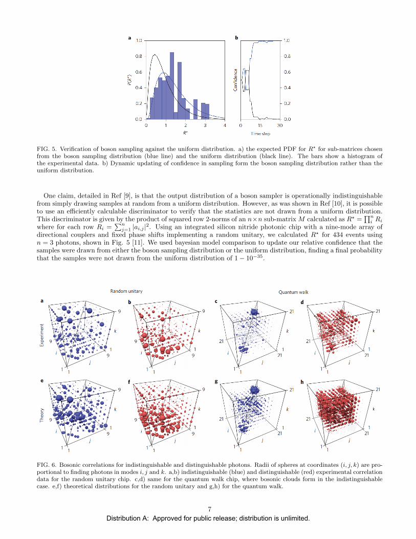
FIG. 5. Verification of boson sampling against the uniform distribution. a) the expected PDF for R? for sub-matrices chosenfrom the boson sampling distribution (blue line) and the uniform distribution (black line). The bars show a histogram ofthe experimental data. b) Dynamic updating of confidence in sampling form the boson sampling distribution rather than theuniform distribution.
One claim, detailed in Ref [9], is that the output distribution of a boson sampler is operationally indistinguishablefrom simply drawing samples at random from a uniform distribution. However, as was shown in Ref [10], it is possibleto use an efficiently calculable discriminator to verify that the statistics are not drawn from a uniform distribution.This discriminator is given by the product of squared row 2-norms of an n×n sub-matrix M calculated as R? =
∏ni Ri
where for each row Ri =∑nj=1 |ai,j |2. Using an integrated silicon nitride photonic chip with a nine-mode array of
directional couplers and fixed phase shifts implementing a random unitary, we calculated R? for 434 events usingn = 3 photons, shown in Fig. 5 [11]. We used bayesian model comparison to update our relative confidence that thesamples were drawn from either the boson sampling distribution or the uniform distribution, finding a final probabilitythat the samples were not drawn from the uniform distribution of 1− 10−35.
FIG. 6. Bosonic correlations for indistinguishable and distinguishable photons. Radii of spheres at coordinates (i, j, k) are pro-portional to finding photons in modes i, j and k. a,b) indistinguishable (blue) and distinguishable (red) experimental correlationdata for the random unitary chip. c,d) same for the quantum walk chip, where bosonic clouds form in the indistinguishablecase. e,f) theoretical distributions for the random unitary and g,h) for the quantum walk.
7
Distribution A: Approved for public release; distribution is unlimited.
One of the main experimental challenges in boson sampling is producing photons which are indistinguishable inall non-spatial degrees of freedom (e.g. polarisation, frequency). If the photons are distinguishable from each other,no quantum interference takes place, leading to a classically tractable distribution. Therefore this is a more physi-cally motivated distribution which needs to be ruled out. The method introduced in [11], approaches this problemby considering, instead of a random unitary, a highly structured unitary for which certain parts of the n photonprobability distribution can be determined efficiently. After experimentally confirming correct operation in this config-uration, we then imagine the circuit can be continuously tuned to a random unitary whilst maintaining this operation.
For a proof-of-principle demonstration of this approach, we used two circuits, the 9x9 random unitary describedabove and a quantum walk chip comprising of an array of 21 evanescently coupled waveguides fabricated in siliconoxynitride, and physically swapped them. The unitary description of the quantum walk device is given by exponen-tiating a nearest-neighbour Hamiltonian resulting in a well structured matrix. The reason this unitary is chosen isthat it exhibits a behaviour we term ’bosonic clouding’ whereby indistinguishable photons tend to cluster in nearbymodes in a superposition around two locations, a tendency not seen in the classical case.
Fig. 6 shows experimental correlations between three photon detections for the random unitary, where there is littlestructure in either case and the quantum walk where bosonic clouding can clearly be seen in the indistinguishablecase but not in the distinguishable case. To quantify the amount of clouding in a given experiment, we construct aclouding metric C. For a given trial i, if t and b are the numbers of photons found in the top and bottom halves of thedevice we calculate ci = 2|(t− b)/(t+ b)| − 1, the clouding metric is then calculated as the average of this value overall n trials, C =
∑i ci/n. For 3 photons we found a value of ∆C = CQ − CC = 0.138± 0.014 revealing the presence of
clouding. For states of 5 photons, where the Hilbert space of the system has a dimension of over 50,000, we still findsuch a separation ∆C = 0.137± 0.041.
VI. QUANTUM-ENHANCED TOMOGRAPHY OF UNITARY PROCESSES
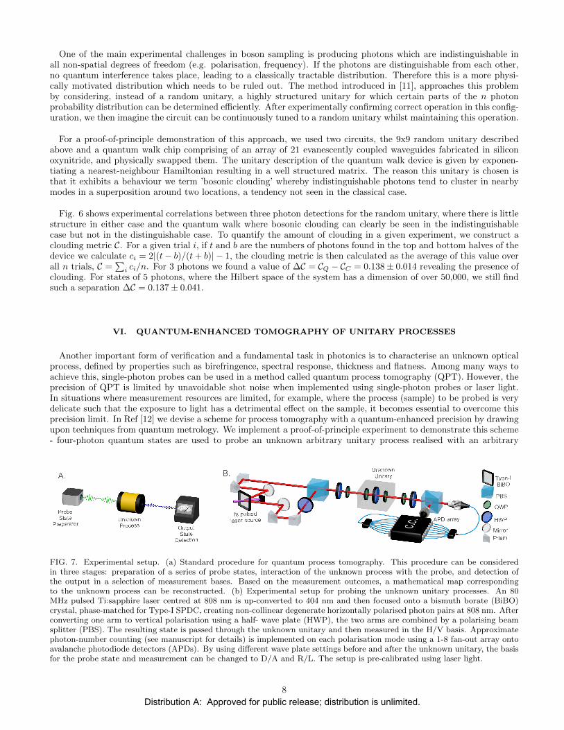
Another important form of verification and a fundamental task in photonics is to characterise an unknown opticalprocess, defined by properties such as birefringence, spectral response, thickness and flatness. Among many ways toachieve this, single-photon probes can be used in a method called quantum process tomography (QPT). However, theprecision of QPT is limited by unavoidable shot noise when implemented using single-photon probes or laser light.In situations where measurement resources are limited, for example, where the process (sample) to be probed is verydelicate such that the exposure to light has a detrimental effect on the sample, it becomes essential to overcome thisprecision limit. In Ref [12] we devise a scheme for process tomography with a quantum-enhanced precision by drawingupon techniques from quantum metrology. We implement a proof-of-principle experiment to demonstrate this scheme- four-photon quantum states are used to probe an unknown arbitrary unitary process realised with an arbitrary
FIG. 7. Experimental setup. (a) Standard procedure for quantum process tomography. This procedure can be consideredin three stages: preparation of a series of probe states, interaction of the unknown process with the probe, and detection ofthe output in a selection of measurement bases. Based on the measurement outcomes, a mathematical map correspondingto the unknown process can be reconstructed. (b) Experimental setup for probing the unknown unitary processes. An 80MHz pulsed Ti:sapphire laser centred at 808 nm is up-converted to 404 nm and then focused onto a bismuth borate (BiBO)crystal, phase-matched for Type-I SPDC, creating non-collinear degenerate horizontally polarised photon pairs at 808 nm. Afterconverting one arm to vertical polarisation using a half- wave plate (HWP), the two arms are combined by a polarising beamsplitter (PBS). The resulting state is passed through the unknown unitary and then measured in the H/V basis. Approximatephoton-number counting (see manuscript for details) is implemented on each polarisation mode using a 1-8 fan-out array ontoavalanche photodiode detectors (APDs). By using different wave plate settings before and after the unknown unitary, the basisfor the probe state and measurement can be changed to D/A and R/L. The setup is pre-calibrated using laser light.
8
Distribution A: Approved for public release; distribution is unlimited.
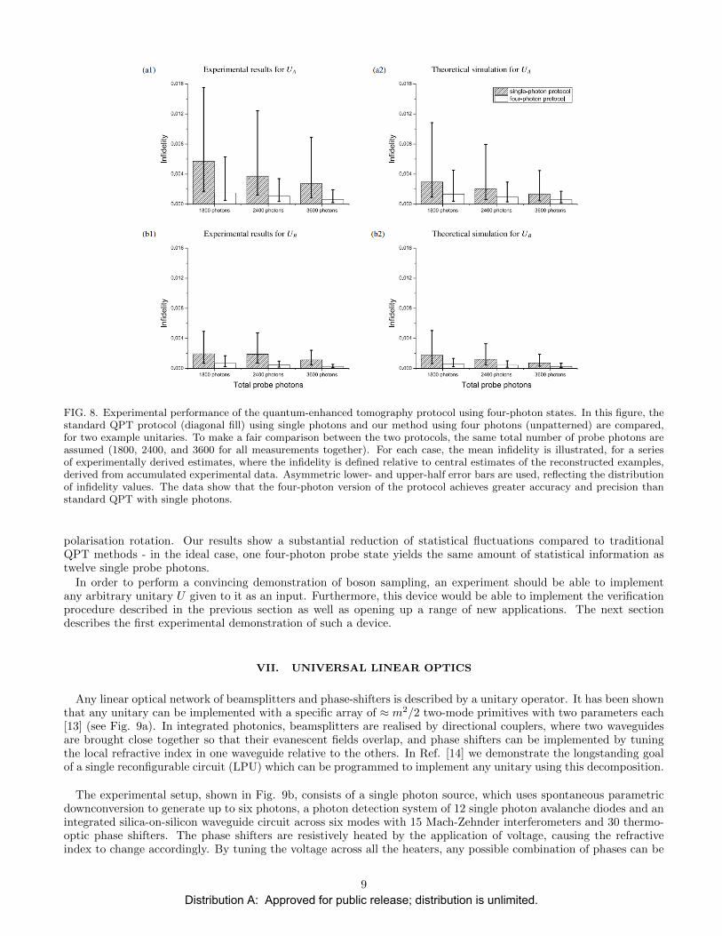
FIG. 8. Experimental performance of the quantum-enhanced tomography protocol using four-photon states. In this figure, thestandard QPT protocol (diagonal fill) using single photons and our method using four photons (unpatterned) are compared,for two example unitaries. To make a fair comparison between the two protocols, the same total number of probe photons areassumed (1800, 2400, and 3600 for all measurements together). For each case, the mean infidelity is illustrated, for a seriesof experimentally derived estimates, where the infidelity is defined relative to central estimates of the reconstructed examples,derived from accumulated experimental data. Asymmetric lower- and upper-half error bars are used, reflecting the distributionof infidelity values. The data show that the four-photon version of the protocol achieves greater accuracy and precision thanstandard QPT with single photons.
polarisation rotation. Our results show a substantial reduction of statistical fluctuations compared to traditionalQPT methods - in the ideal case, one four-photon probe state yields the same amount of statistical information astwelve single probe photons.
In order to perform a convincing demonstration of boson sampling, an experiment should be able to implementany arbitrary unitary U given to it as an input. Furthermore, this device would be able to implement the verificationprocedure described in the previous section as well as opening up a range of new applications. The next sectiondescribes the first experimental demonstration of such a device.
VII. UNIVERSAL LINEAR OPTICS
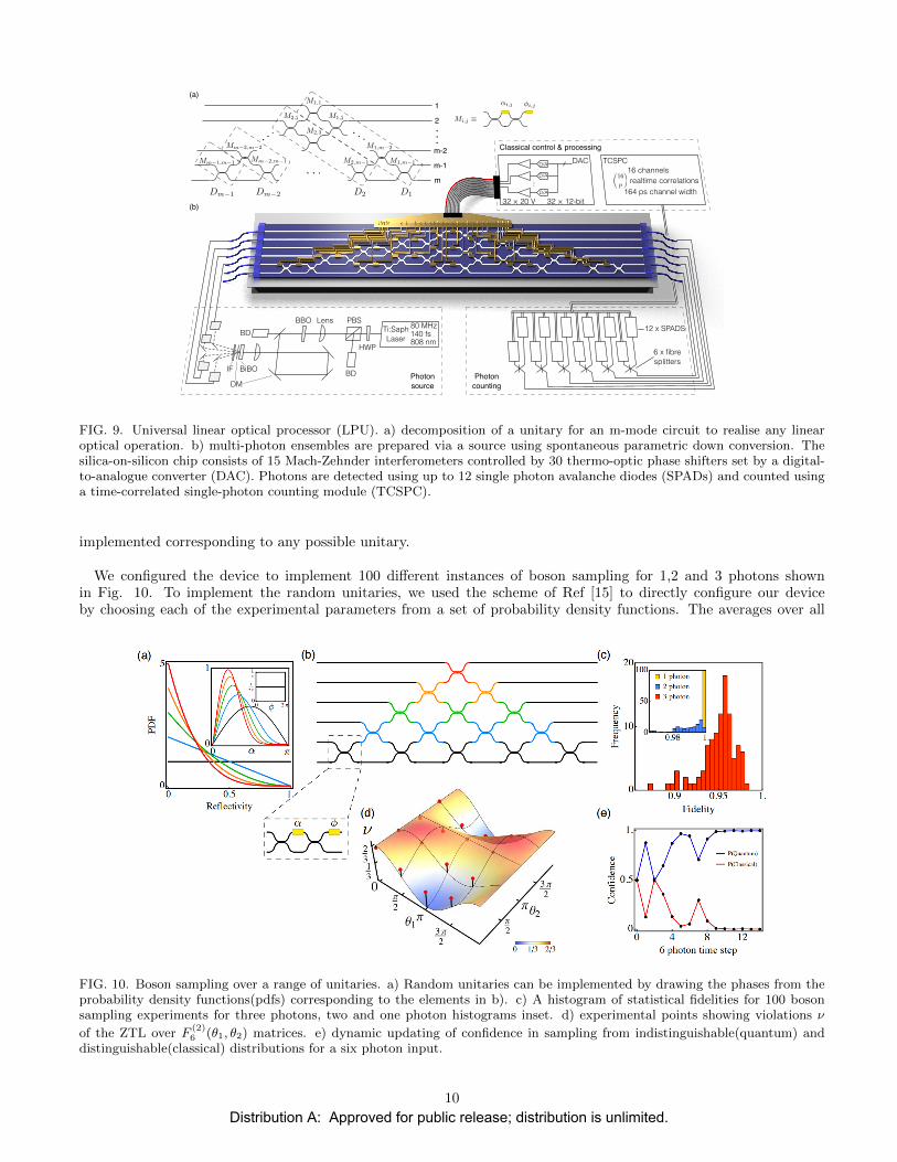
Any linear optical network of beamsplitters and phase-shifters is described by a unitary operator. It has been shownthat any unitary can be implemented with a specific array of ≈ m2/2 two-mode primitives with two parameters each[13] (see Fig. 9a). In integrated photonics, beamsplitters are realised by directional couplers, where two waveguidesare brought close together so that their evanescent fields overlap, and phase shifters can be implemented by tuningthe local refractive index in one waveguide relative to the others. In Ref. [14] we demonstrate the longstanding goalof a single reconfigurable circuit (LPU) which can be programmed to implement any unitary using this decomposition.
The experimental setup, shown in Fig. 9b, consists of a single photon source, which uses spontaneous parametricdownconversion to generate up to six photons, a photon detection system of 12 single photon avalanche diodes and anintegrated silica-on-silicon waveguide circuit across six modes with 15 Mach-Zehnder interferometers and 30 thermo-optic phase shifters. The phase shifters are resistively heated by the application of voltage, causing the refractiveindex to change accordingly. By tuning the voltage across all the heaters, any possible combination of phases can be
9
Distribution A: Approved for public release; distribution is unlimited.
TCSPC16 channels
Photon source
Classical control & processing
32 × 12-bit32 × 20 V
DACD/A
D/A
D/A
…
12 x SPADS
Photon counting
6 x fibre splitters
(a)
(b)
✓16
p
◆realtime correlations
164 ps channel width
BD
↵i,j �i,j
Mi,j ⌘
...
1
2
m-2
m
m-1
Dm�1
M1,1
M1,2
M1,m�1
M1,m�2
M2,2
M2,3
M2,m�1
Mm�2,m�2
Mm�2,m�1Mm�1,m�1
. ..
. . .
. . .
Dm�2 D2 D1
80 MHz
808 nm140 fs
BD
PBS
HWP
Ti:SaphLaser
LensBBO
BiBOIF
DM
FIG. 9. Universal linear optical processor (LPU). a) decomposition of a unitary for an m-mode circuit to realise any linearoptical operation. b) multi-photon ensembles are prepared via a source using spontaneous parametric down conversion. Thesilica-on-silicon chip consists of 15 Mach-Zehnder interferometers controlled by 30 thermo-optic phase shifters set by a digital-to-analogue converter (DAC). Photons are detected using up to 12 single photon avalanche diodes (SPADs) and counted usinga time-correlated single-photon counting module (TCSPC).
implemented corresponding to any possible unitary.
We configured the device to implement 100 different instances of boson sampling for 1,2 and 3 photons shownin Fig. 10. To implement the random unitaries, we used the scheme of Ref [15] to directly configure our deviceby choosing each of the experimental parameters from a set of probability density functions. The averages over all
FIG. 10. Boson sampling over a range of unitaries. a) Random unitaries can be implemented by drawing the phases from theprobability density functions(pdfs) corresponding to the elements in b). c) A histogram of statistical fidelities for 100 bosonsampling experiments for three photons, two and one photon histograms inset. d) experimental points showing violations ν
of the ZTL over F(2)6 (θ1, θ2) matrices. e) dynamic updating of confidence in sampling from indistinguishable(quantum) and
distinguishable(classical) distributions for a six photon input.
10
Distribution A: Approved for public release; distribution is unlimited.

hundred unitaries of the statistical fidelity of the resulting probability distributions, defined as Fs =∑i
√piqi, were
found to be 0.999± 0.001,0.990± 0.007 and 0.950± 0.020 respectively.
The ability to arbitrarily tune the device also allows for a full demonstration of the verification procedure outlinedin the previous section. For this demonstration we used the discrete Fourier transform (FT) matrix as the structuredunitary. The zero transmission law (ZTL) [16] uses the symmetry of the FT matrix to determine that the probabilitiesfor most of the exponentially growing number of correlated photon detections are strictly suppressed for this case.Since this suppression is caused by multi-photon quantum interference, it has been proposed as a stringent assessment
of boson sampling devices [17]. We implemented a range of examples from a two-parameter family F(2)6 (θ1, θ2)
of complex Hadamard matrices (unitaries for which the absolute squared value of every element is 1/N), where
the FT matrix corresponds to F(2)6 (π, 0). Using 3 photons, we calculated the experimental violation of the ZTL as
ν = Ns/N , the ratio of suppressed events Ns to the total number of events N , the results of which are seen in Fig. 10d.
Finally, in Fig. 10e we demonstrated that the chip maintains six photon indistinguishability by inputting 3 photonsinto each of the top two waveguides of the FT matrix and using bayesian model comparison to compare our relativeconfidence of sampling from the correct distribution, finding a final confidence of > 99% that we are sampling fromthe correct distribution .
The ability to implement any circuit opens up a range of new applications and experiments. In the final sectionwe describe ongoing work using the framework of boson sampling to realise a new form of quantum simulator whichcould lead to the first quantum simulations that exceed the capabilities of classical devices.
VIII. QUANTUM SIMULATION OF HARMONIC PHONONS
Simulating the evolution of quantum systems is in general an intractably hard computational task making it a keyapplication of quantum technology for chemistry, biology and material science. In contrast to a digital simulationon a universal quantum computer, analogue quantum simulators use the specific properties of quantum systems inthe lab to simulate similar systems in nature which are physically less accessible or controllable. By exploiting thenatural Hamiltonian of the given system the resources required to perform a non-trivial quantum simulation can begreatly reduced.
A common approach to simulating the dynamics of interacting particles involves finding a transformation whichmaps the problem to one of non-interacting particles. One such example is the case of phonons, where the harmonicapproximation (i.e. assuming small displacements) of an atomic Hamiltonian gives rise to collective vibrational quasi-particles which act as non-interacting bosons with well defined energies. The ability to implement and reconfigure
FIG. 11. Simulation of localised phonons in a ring of atoms. a) relative volume of bubbles indicates the relative probability ofdetecting a phonon localised in each of the atomic sites of the ring. Black line indicates the expectation value of the angularposition of a localised phonon (grey if we define the anti-clockwise angular position). b) expected separation between twolocalised phonons. c) same for three phonons.
11
Distribution A: Approved for public release; distribution is unlimited.
any m dimensional unitary transformation on n photons, as described in the previous sections, implies the ability tosimulate any m mode non-interacting Hamiltonian on a system of n bosons [18]. Simulation is then accomplished bytuning the optical elements to implement the unitary operation U(t) = e−iHt that corresponds to the HamiltonianH evolved to the desired time t. The evolution of the system can then be observed by reconfiguring the circuit torealise a sequence of unitaries for each of the desired time steps and tracking the evolving probability distributionover the modes. Since these distributions are governed by permanents, there is reason to believe that simulating thisevolution for many physical scenarios is classically inefficient.
The textbook model of a lattice of atoms describes how phonons arise. Consider m particles with mass M atposition x and connected by springs of constant C and length l in a ring. The transverse displacement of the particleat x is qx and its momentum is px, leading to a Hamiltonian
H =1
2
N∑
x=1
p2x/M + C(qx+1 − qx)2
This system can be simplified by converting between px and qx and their respective Fourier transform coordinatesPk and Qk. In this basis, the motion of the ring is decomposed into the normal modes, or in the quantum casephonons, of the system with corresponding frequencies ωk =
√2C/M
√1− cos(kl). When applying this model to
quantum systems, second quantisation introduces creation and annihilation operators a†k and ak defined on these
phonon modes and produces the Hamiltonian H =∑k(a†kak + 1
2 )~ωk which describes a quantum field theory ofnon-interacting bosons. This Hamiltonian is diagonal and as such its evolution is trivial, however if we considercalculating correlations from an arbitrary measurement basis M =
∑i |i〉〈mi| for many phonons prepared in another
basis P =∑i |pi〉〈i| then we can simulate the evolution U ′(t) = M.eiHt.P . For the case of the ring, if we choose M
and P to be the FT matrix, this corresponds to initially localising phonons at all the sites where photons are inputtedand then simulating their spatial distribution over time as depicted in Fig. 11.
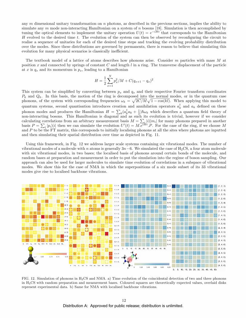
Using this framework, in Fig. 12 we address larger scale systems containing six vibrational modes. The number ofvibrational modes of a molecule with n atoms is generally 3n−6. We simulated the case of H2CS, a four atom moleculewith six vibrational modes, in two bases; the localised basis of phonons around certain bonds of the molecule, andrandom bases at preparation and measurement in order to put the simulation into the regime of boson sampling. Ourapproach can also be used for larger molecules to simulate time evolution of correlations in a subspace of vibrationalmodes. We show this for the case of NMA in which the superpositions of a six mode subset of its 33 vibrationalmodes give rise to localised backbone vibrations.
FIG. 12. Simulation of phonons in H2CS and NMA. a) Time evolution of the coincidental detection of two and three phononsin H2CS with random preparation and measurement bases. Coloured squares are theoretically expected values, overlaid disksrepresent experimental data. b) Same for NMA with localised backbone vibrations.
12
Distribution A: Approved for public release; distribution is unlimited.
We have shown that photons propagating in a fully reconfigurable linear optical circuit can function as a simulatorwhich is universal for the class of non-interacting bosons. Due to the relatively low experimental resources required,and the theoretical evidence that such systems are not efficiently simulatable, this suggests that such an approachcould yield the very first meaningful quantum simulations which are not possible with classical computation.
IX. CONCLUSIONS
Here we have described the rapid progress achieved at the CQP towards the major goal of an integrated photonicsystem capable of outperforming classical computers. We have demonstrated experimental and theoretical solutionsto improve the scalability of single photon sources and proposed new verification protocols clearing the way forlarge-scale multi-photon experiments. In addition, through the development of universally reconfigurable circuits wehave opened up the possibility of performing physically meaningful, classically intractable simulations with minimalquantum resources.
Combining the development of integrated on-chip photon sources [19] with the source-boosting schemes describedin Sections II and III will enable the monolithic implementation of arrays of single photon sources in order to producethe 10s of photons needed for photonic simulations beyond the capability of conventional computers. Integratingsingle photon detectors on-chip is also an immediate goal as this will allow for high-efficiency detection and dramat-ically reduce the detrimental effects of photon loss. Alongside these developments we will look to increase the sizeof reconfigurable circuitry, allowing for larger-scale and more sophisticated experiments exploring large dimensionalHilbert spaces where verification protocols will be essential.
Work must now be done to further develop theory for physical scenarios where photonics simulators will findapplication. A natural extension to the molecular simulations described in Section VIII is to introduce some non-linearities into the photon sources (e.g. by squeezing) or circuit (e.g. by heralded quantum logic), which can bemapped to vibrational couplings in molecules. Such a system would allow for an improvement to the accuracy of themolecular model, opening up new and important possibilities across science, such as new drug design.
X. LIST OF PUBLICATIONS SUPPORTED BY USAF
• J. Carolan et al., ‘On the experimental verification of quantum complexity in linear optics’, Nat. Photon., 8 ,621-626, (2014)
• A. Lund et al.,‘Boson Sampling from a Gaussian State’, Phys. Rev. Lett., 113, 100502, (2014)
• X-Q Zhou et al., ‘Quantum-enhanced tomography of unitary processes’, Optica, 2, 510-516, (2015)
• J. Carolan et al.,‘Universal linear optics’, Science, 349, 711-716, (2015)
• N. Russell et al., ‘Direct dialling of Haar random unitary matrices’ arXiv:1506.06220, (2015)
• G. Mendoza et al., ‘Active Temporal Multiplexing of Photons’, arXiv:1503.01215, (2015)
• E. Martin-Lopez et al., ‘Quantum Simulation of Harmonic Phonons’, In Preparation
[1] S. Aaronson and A. Arkhipov, in STOC ’11: Proceedings of the 43rd annual ACM symposium on Theory of computing,San Jose (ACM, New York, 2011) pp. 333–342.
[2] J. B. Spring, B. J. Metcalf, P. C. Humphreys, W. S. Kolthammer, X.-M. Jin, M. Barbieri, A. Datta, N. Thomas-Peter,N. K. Langford, D. Kundys, J. C. Gates, B. J. Smith, P. G. R. Smith, and I. A. Walmsley, Science 339, 798 (2013).
[3] A. Politi, M. J. Cryan, J. G. Rarity, S. Yu, and J. L. O’Brien, Science 320, 646 (2008).[4] S. Sohma, T. Watanabe, N. Ooba, M. Itoh, T. Shibata, and H. Takahashi, in Optical Communications, 2006. ECOC 2006.
European Conference on (IEEE, 2006) pp. 1–2.[5] M. D. Eisaman, J. Fan, A. Migdall, and S. V. Polyakov, Review of Scientific Instruments 82, 071101 (2011).[6] G. J. Mendoza, R. Santagati, J. Munns, E. Hemsley, M. Piekarek, E. Martin-Lopez, G. D. Marshall, D. Bonneau, M. G.
Thompson, and J. L. O’Brien, (2015), arXiv:1503.01215.
13
Distribution A: Approved for public release; distribution is unlimited.
[7] A. P. Lund, A. Laing, S. Rahimi-Keshari, T. Rudolph, J. L. O’Brien, and T. C. Ralph, Phys. Rev. Lett. 113, 100502(2014).
[8] M. Bentivegna, N. Spagnolo, C. Vitelli, F. Flamini, N. Viggianiello, L. Latmiral, P. Mataloni, D. J. Brod, E. F. Galvao,A. Crespi, R. Ramponi, R. Osellame, and F. Sciarrino, Science Advances 1 (2015), 10.1126/sciadv.1400255.
[9] C. Gogolin, M. Kliesch, L. Aolita, and J. Eisert, (2013), arXiv:quant-ph/1306.3995.[10] S. Aaronson and A. Arkhipov, (2013), arXiv:quant-ph/1309.7460.[11] J. Carolan, J. D. A. Meinecke, P. J. Shadbolt, N. J. Russell, N. Ismail, K. Worhoff, T. Rudolph, M. G. Thompson, J. L.
O’Brien, J. C. F. Matthews, and A. Laing, Nat. Photon. 8, 621 (2014).[12] X.-Q. Zhou, H. Cable, R. Whittaker, P. Shadbolt, J. L. O’Brien, and J. C. F. Matthews, Optica 2, 510 (2015).[13] M. Reck, A. Zeilinger, H. J. Bernstein, and P. Bertani, Phys. Rev. Lett. 73, 58 (1994).[14] J. Carolan, C. Harrold, C. Sparrow, E. Martin-Lopez, N. J. Russell, J. W. Silverstone, P. J. Shadbolt, N. Matsuda,
M. Oguma, M. Itoh, G. D. Marshall, M. G. Thompson, J. C. F. Matthews, T. Hashimoto, J. L. O’Brien, and A. Laing,Science 349, 711 (2015).
[15] N. J. Russell, J. L. O’Brien, and A. Laing, (2015), arXiv:1506.06220.[16] M. C. Tichy, M. Tiersch, F. de Melo, F. Mintert, and A. Buchleitner, Phys. Rev. Lett. 104, 220405 (2010).[17] M. C. Tichy, K. Mayer, A. Buchleitner, and K. Molmer, Phys. Rev. Lett. 113, 020502 (2014).[18] E. Martin-Lopez, J. L. O’Brien, and A. Laing, In preparation (2015).[19] J. W. Silverstone, D. Bonneau, K. Ohira, N. Suzuki, H. Yoshida, N. Iizuka, M. Ezaki, C. M. Natarajan, M. G. Tanner,
R. H. Hadfield, et al., Nature Photonics 8, 104 (2014).
14
Distribution A: Approved for public release; distribution is unlimited.