Embed Size (px)
Citation preview
Rev draft 2 6/29/2013 Author John Propst Technical Review Pending by Bill Pancake
1
Aeronca and the Hummer Starter
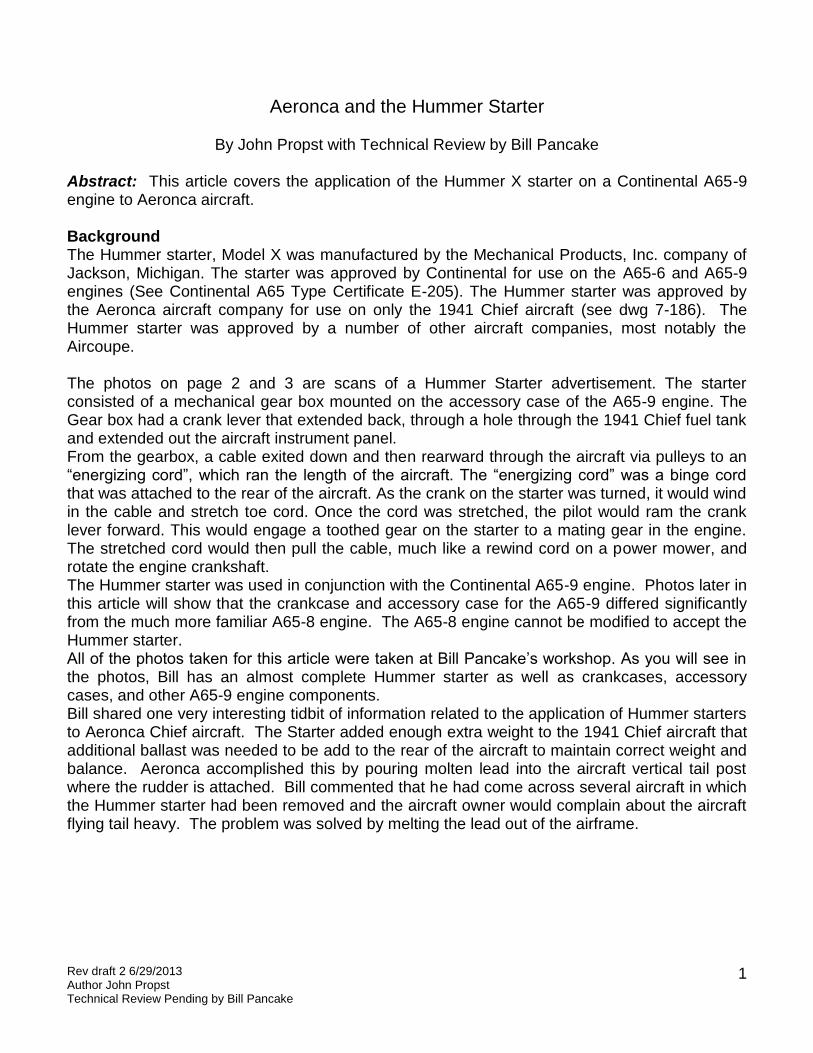
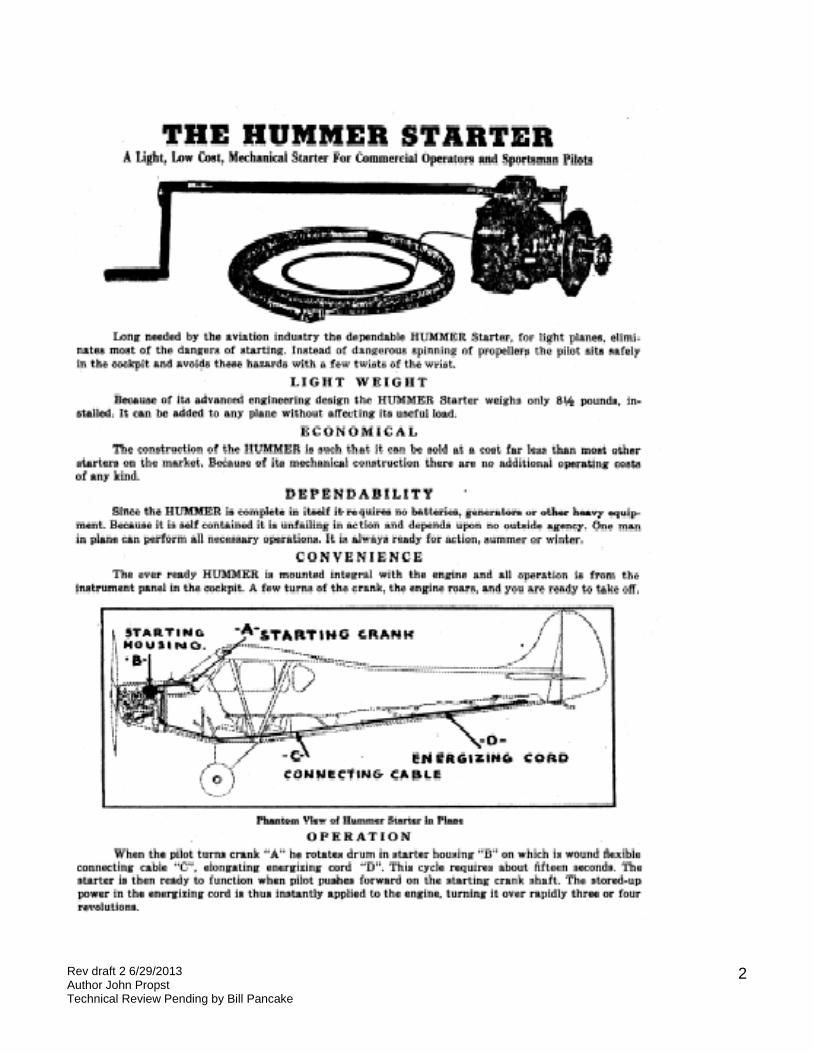
By John Propst with Technical Review by Bill Pancake Abstract: This article covers the application of the Hummer X starter on a Continental A65-9 engine to Aeronca aircraft. Background The Hummer starter, Model X was manufactured by the Mechanical Products, Inc. company of Jackson, Michigan. The starter was approved by Continental for use on the A65-6 and A65-9 engines (See Continental A65 Type Certificate E-205). The Hummer starter was approved by the Aeronca aircraft company for use on only the 1941 Chief aircraft (see dwg 7-186). The Hummer starter was approved by a number of other aircraft companies, most notably the Aircoupe. The photos on page 2 and 3 are scans of a Hummer Starter advertisement. The starter consisted of a mechanical gear box mounted on the accessory case of the A65-9 engine. The Gear box had a crank lever that extended back, through a hole through the 1941 Chief fuel tank and extended out the aircraft instrument panel. From the gearbox, a cable exited down and then rearward through the aircraft via pulleys to an “energizing cord”, which ran the length of the aircraft. The “energizing cord” was a binge cord that was attached to the rear of the aircraft. As the crank on the starter was turned, it would wind in the cable and stretch toe cord. Once the cord was stretched, the pilot would ram the crank lever forward. This would engage a toothed gear on the starter to a mating gear in the engine. The stretched cord would then pull the cable, much like a rewind cord on a power mower, and rotate the engine crankshaft. The Hummer starter was used in conjunction with the Continental A65-9 engine. Photos later in this article will show that the crankcase and accessory case for the A65-9 differed significantly from the much more familiar A65-8 engine. The A65-8 engine cannot be modified to accept the Hummer starter. All of the photos taken for this article were taken at Bill Pancake’s workshop. As you will see in the photos, Bill has an almost complete Hummer starter as well as crankcases, accessory cases, and other A65-9 engine components. Bill shared one very interesting tidbit of information related to the application of Hummer starters to Aeronca Chief aircraft. The Starter added enough extra weight to the 1941 Chief aircraft that additional ballast was needed to be add to the rear of the aircraft to maintain correct weight and balance. Aeronca accomplished this by pouring molten lead into the aircraft vertical tail post where the rudder is attached. Bill commented that he had come across several aircraft in which the Hummer starter had been removed and the aircraft owner would complain about the aircraft flying tail heavy. The problem was solved by melting the lead out of the airframe.
Rev draft 2 6/29/2013 Author John Propst Technical Review Pending by Bill Pancake
2
Rev draft 2 6/29/2013 Author John Propst Technical Review Pending by Bill Pancake
3
Rev draft 2 6/29/2013 Author John Propst Technical Review Pending by Bill Pancake
4
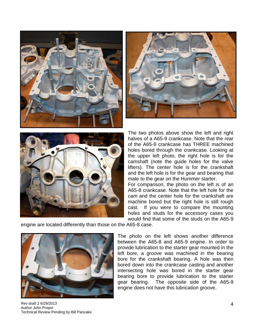
The two photos above show the left and right halves of a A65-9 crankcase. Note that the rear of the A65-9 crankcase has THREE machined holes bored through the crankcase. Looking at the upper left photo, the right hole is for the camshaft (note the guide holes for the valve lifters). The center hole is for the crankshaft and the left hole is for the gear and bearing that mate to the gear on the Hummer starter. For comparison, the photo on the left is of an A65-8 crankcase. Note that the left hole for the cam and the center hole for the crankshaft are machine bored but the right hole is still rough cast. If you were to compare the mounting holes and studs for the accessory cases you would find that some of the studs on the A65-9
engine are located differently than those on the A65-8 case.
The photo on the left shows another difference between the A65-8 and A65-9 engine. In order to provide lubrication to the starter gear mounted in the left bore, a groove was machined in the bearing bore for the crankshaft bearing. A hole was then bored down into the crankcase casting and another intersecting hole was bored in the starter gear bearing bore to provide lubrication to the starter gear bearing. The opposite side of the A65-9 engine does not have this lubrication groove.
Rev draft 2 6/29/2013 Author John Propst Technical Review Pending by Bill Pancake
5
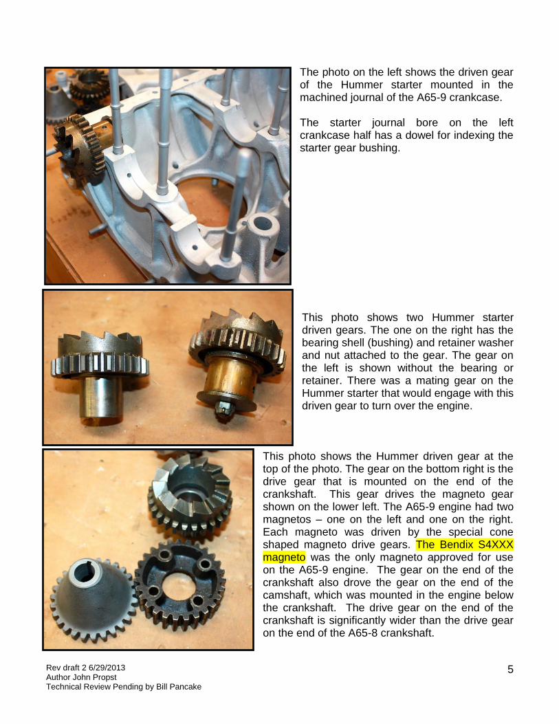
The photo on the left shows the driven gear of the Hummer starter mounted in the machined journal of the A65-9 crankcase. The starter journal bore on the left crankcase half has a dowel for indexing the starter gear bushing.
This photo shows two Hummer starter driven gears. The one on the right has the bearing shell (bushing) and retainer washer and nut attached to the gear. The gear on the left is shown without the bearing or retainer. There was a mating gear on the Hummer starter that would engage with this driven gear to turn over the engine.
This photo shows the Hummer driven gear at the top of the photo. The gear on the bottom right is the drive gear that is mounted on the end of the crankshaft. This gear drives the magneto gear shown on the lower left. The A65-9 engine had two magnetos – one on the left and one on the right. Each magneto was driven by the special cone shaped magneto drive gears. The Bendix S4XXX magneto was the only magneto approved for use on the A65-9 engine. The gear on the end of the crankshaft also drove the gear on the end of the camshaft, which was mounted in the engine below the crankshaft. The drive gear on the end of the crankshaft is significantly wider than the drive gear on the end of the A65-8 crankshaft.
Rev draft 2 6/29/2013 Author John Propst Technical Review Pending by Bill Pancake
6
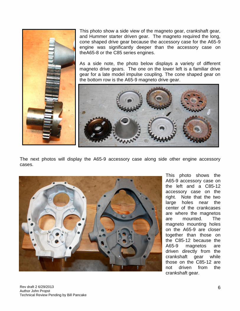
This photo show a side view of the magneto gear, crankshaft gear, and Hummer starter driven gear. The magneto required the long, cone shaped drive gear because the accessory case for the A65-9 engine was significantly deeper than the accessory case on theA65-8 or the C85 series engines. As a side note, the photo below displays a variety of different magneto drive gears. The one on the lower left is a familiar drive gear for a late model impulse coupling. The cone shaped gear on the bottom row is the A65-9 magneto drive gear.
The next photos will display the A65-9 accessory case along side other engine accessory cases.
This photo shows the A65-9 accessory case on the left and a C85-12 accessory case on the right. Note that the two large holes near the center of the crankcases are where the magnetos are mounted. The magneto mounting holes on the A65-9 are closer together than those on the C85-12 because the A65-9 magnetos are driven directly from the crankshaft gear while those on the C85-12 are not driven from the crankshaft gear.
Rev draft 2 6/29/2013 Author John Propst Technical Review Pending by Bill Pancake
7
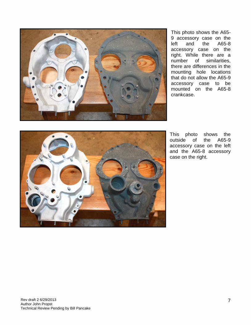
This photo shows the A65-9 accessory case on the left and the A65-8 accessory case on the right. While there are a number of similarities, there are differences in the mounting hole locations that do not allow the A65-9 accessory case to be mounted on the A65-8 crankcase. This photo shows the outside of the A65-9 accessory case on the left and the A65-8 accessory case on the right.
Rev draft 2 6/29/2013 Author John Propst Technical Review Pending by Bill Pancake
8
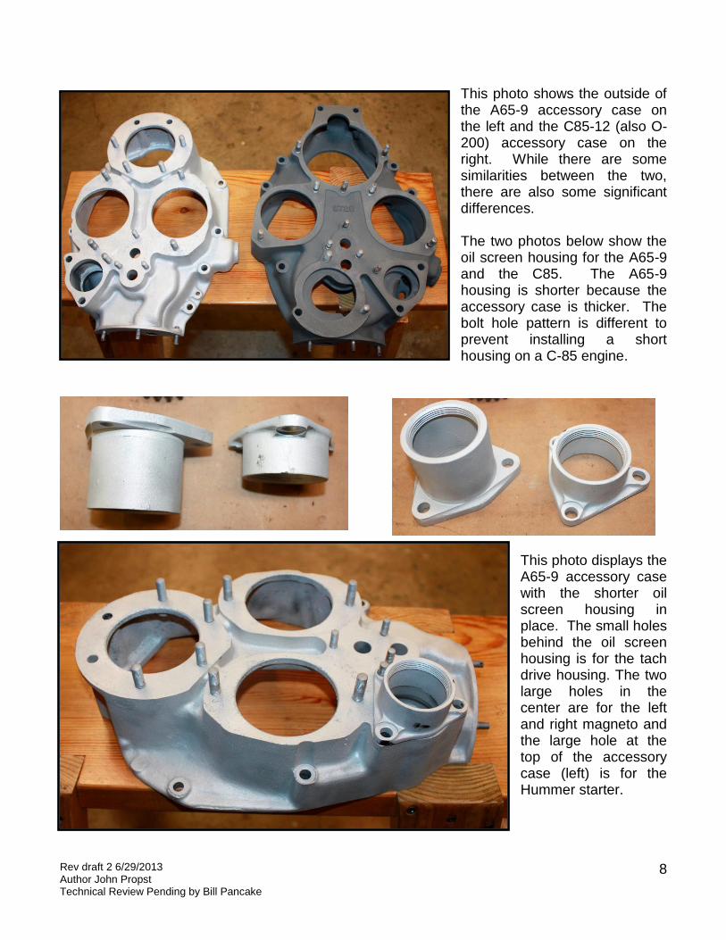
This photo shows the outside of the A65-9 accessory case on the left and the C85-12 (also O-200) accessory case on the right. While there are some similarities between the two, there are also some significant differences. The two photos below show the oil screen housing for the A65-9 and the C85. The A65-9 housing is shorter because the accessory case is thicker. The bolt hole pattern is different to prevent installing a short housing on a C-85 engine.
This photo displays the A65-9 accessory case with the shorter oil screen housing in place. The small holes behind the oil screen housing is for the tach drive housing. The two large holes in the center are for the left and right magneto and the large hole at the top of the accessory case (left) is for the Hummer starter.
Rev draft 2 6/29/2013 Author John Propst Technical Review Pending by Bill Pancake
9
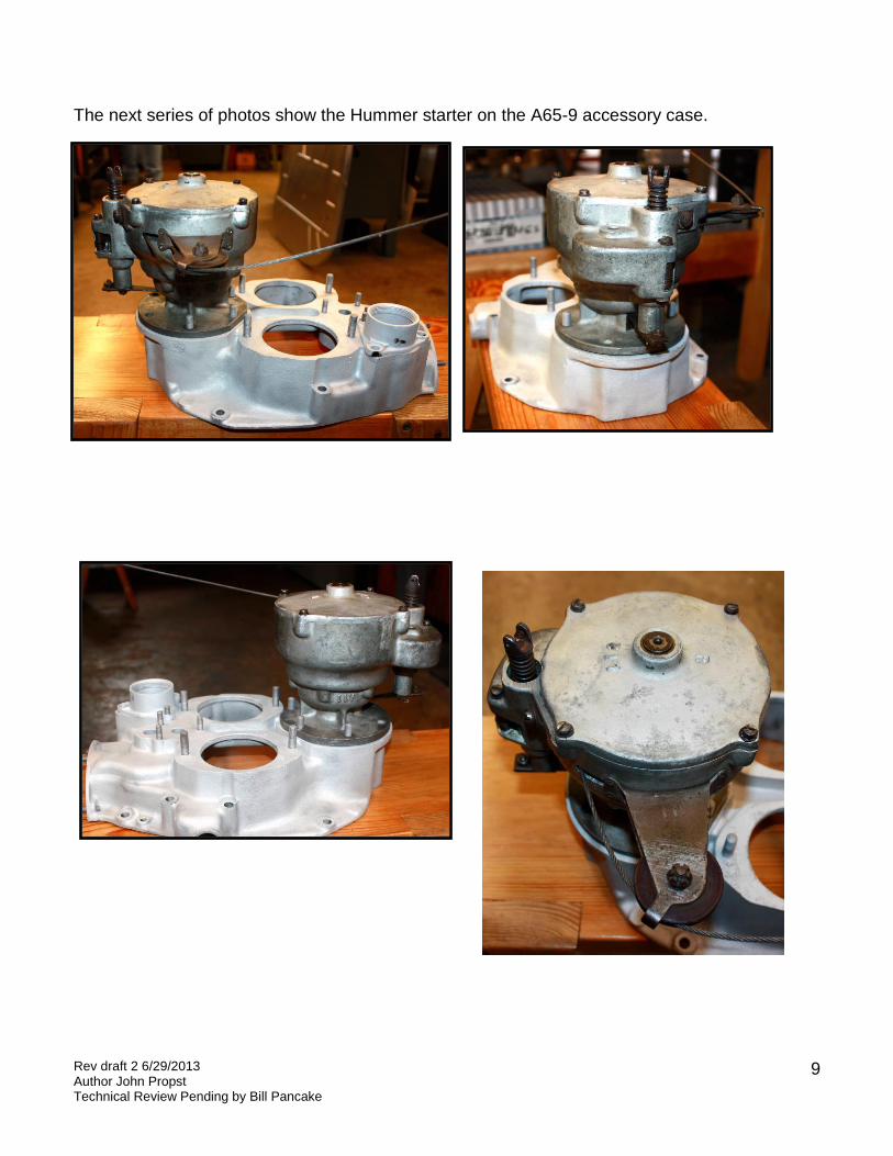
The next series of photos show the Hummer starter on the A65-9 accessory case.
Rev draft 2 6/29/2013 Author John Propst Technical Review Pending by Bill Pancake
10
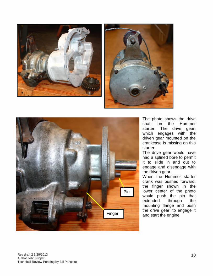
The photo shows the drive shaft on the Hummer starter. The drive gear, which engages with the driven gear mounted on the crankcase is missing on this starter. The drive gear would have had a splined bore to permit it to slide in and out to engage and disengage with the driven gear. When the Hummer starter crank was pushed forward, the finger shown in the lower center of the photo would push the pin that extended through the mounting flange and push the drive gear, to engage it and start the engine.
Pin
Finger
Rev draft 2 6/29/2013 Author John Propst Technical Review Pending by Bill Pancake
11